Embed Size (px)
Citation preview

at Lewis Field Glenn Research Center
Affordable Development and Demonstration of a Small NTR Engine and Stage: A Preliminary NASA, DOE and Industry Assessment
– Invited Talk –
EXPL-01 Advanced Propulsion for Exploration
S. K. Borowski and R. J. Sefcik (NASA GRC) A. L. Qualls and B. G. Schnitzler (ORNL)
C. R. Joyner (Aerojet Rocketdyne) 216-977-7091, [email protected]
presented at the
AIAA Space & Astronautics Forum & Exposition (Space 2014)
San Diego, CA
Tuesday, August 5, 2014
https://ntrs.nasa.gov/search.jsp?R=20140017460 2018-12-03T09:35:22+00:00Z
at Lewis Field Glenn Research Center
Contributors
W.M. Marshall1, T.J. Parkey1, M. G. Houts2, J. W. Warren3, J. E. Fittje4, D. R. McCurdy4 A.�L. Qualls5, B. G. Schnitzler5, A. D. Belvin6, S. D Howe7 and C. R. Joyner8
1NASA Glenn Research Center, Cleveland, OH 44135 2NASA Marshall Space Flight Center, MSFC, AL 35812
3NASA Headquarters, Washington, DC 20546 4Vantage Partners, LLC at Glenn Research Center, Brook Park, OH 44142
5Oak Ridge National Laboratory, Oak Ridge, TN 37831 6US Department of Energy, Washington, DC 20585
7Center for Space Nuclear Research, Idaho National Laboratory, Idaho Falls, ID 83402 8Aerojet Rocketdyne, West Palm Beach, FL 33410

at Lewis Field Glenn Research Center
• In FY�11, Nuclear Thermal Propulsion (NTP) was identified as a key propulsion option under the � Advanced In-Space Propulsion (AISP) component of NASA’s Exploration Technology Development � and Demonstration (ETDD) program�
• A strategy was outlined by GRC and NASA HQ that included 2 key elements – �Foundational � Technology Development� followed by specific �Technology Demonstration��projects�
• The �Technology Demonstration� element proposed ground technology demonstration (GTD) � testing in the early 2020’s, followed by a flight technology demonstration (FTD) mission by 2025�
• In order to reduce development costs, the demonstration projects would focus on developing a � smaller, lower thrust (~7.5 klbf) engine that utilizes a �common� fuel element design scalable � to the higher thrust (~25 klbf) engines used in NASA’s Mars DRA 5.0 study (NASA-SP-2009-566)�
• Besides reducing development costs and allowing utilization of existing, flight proven engine hard-� ware (e.g., hydrogen pumps and nozzles), small, lower thrust ground and flight demonstration � engines can validate the technology and offer improved capability – increased payloads and � decreased transit times – valued for robotic science missions identified in NASA�s Decadal Study�
• NASA, DOE (NE-75, ORNL, INL) and industry (Aerojet Rocketdyne) are working together on � formulating a strategy leading to the development of a small GTD (~7.5 klbf) engine in the early � 2020�s followed by a FTD �lunar flyby� mission using a small NTP stage (SNTPS) around 2025�
• The preliminary assessment provided here along with similar information proposed by DOE/NE-75� provides a strawman for continued refinement allowing an informed cost estimate to be made��
Formulation of Affordable and Sustainable NTP Development �Strategy is Underway Involving NASA, DOE and Industry �

at Lewis Field Glenn Research Center
GTA2 Ground Test Article 2
FTA Flight Test Article
FTD Flight Tech Demo
2027202620252023202020192017 2021 2022 202420182016Fiscal Year 20152014
Key Milestones
Ground Test Article 1
Test Articles for Ground & Flight
Ground Test Facility (GTF)
Foundational Technology Development
GTD
Ground & Flight Technology Demonstrators
NTP Test Facilities Development
System Concepts & Requirements Definition / Planning / Engine Modeling & Analysis
NTP Technology Development and Demonstrations
GTA1
2031-33
2033-35
2029-30
Potential Demos / Mars Flights
- Mars Crewed Flights
- Mars Cargo Flights
- Lunar/EM-L2 Flights
Ground Tech Demo
ATP 7.5-klbf Engine FTD
In-House & Contractor System Concept Definition, Design, and Analysis
Prel. & Final
Design
Construction &
Asset Installation
Check
-out
GTA2 GTA1 Detailed
Design
Fabrication &
Subsys. Assembly
Subsys. Test /
Engine Assem.
Primary / Secondary Fuels Selection
Fuels Selection
CDR GTA
Start
Initial GTD Design
End
GTD Engine Tests
Advanced NTP Tech Dev Includes Fuels & Bimodal Concepts
Borehole Demo Testing
GTF Plan'g/Prel Des
Hot H2 Testing in NTREES & DOE Reactor Irradiation Tests
Reference Concept & Initial Requirements
Initial FTD Design Initial 25-klbf GTD / FTD Designs
CDR FTA
Fuel Element Fab, Testing, Validation and Production; Irradiation Testing / PIE; Other Tech Development
FTA Detailed
Design
Fabrication &
Subsys. Assembly
Subsys. Test /
Engine Assem.

at Lewis Field Glenn Research Center
SOTA Reactor Core & Engine Modeling
GTA2 Ground Test Article 2
FTA Flight Test Article
FTD Flight Tech Demo
2027202620252023202020192017 2021 2022 202420182016Fiscal Year 20152014
Key Milestones
Ground Test Article 1
Test Articles for Ground & Flight
Ground Test Facility (GTF)
Foundational Technology Development
GTD
Ground & Flight Technology Demonstrators
NTP Test Facilities Development
System Concepts & Requirements Definition / Planning / Engine Modeling & Analysis
NTP Technology Development and Demonstrations
GTA1
2031-33
2033-35
2029-30
Potential Demos / Mars Flights
- Mars Crewed Flights
- Mars Cargo Flights
- Lunar/EM-L2 Flights
Ground Tech Demo
ATP 7.5-klbf Engine FTD
In-House & Contractor System Concept Definition, Design, and Analysis
Prel. & Final
Design
Construction &
Asset Installation
Check
-out
GTA2 GTA1 Detailed
Design
Fabrication &
Subsys. Assembly
Subsys. Test /
Engine Assem.
Primary / Secondary Fuels Selection
Fuels Selection
CDR GTA
Start
Initial GTD Design
End
GTD Engine Tests
Advanced NTP Tech Dev Includes Fuels & Bimodal Concepts
Borehole Demo Testing
GTF Plan'g/Prel Des
Hot H2 Testing in NTREES & DOE Reactor Irradiation Tests
Reference Concept & Initial Requirements
Initial FTD Design Initial 25-klbf GTD / FTD Designs
CDR FTA
Fuel Element Fab, Testing, Validation and Production; Irradiation Testing / PIE; Other Tech Development
FTA Detailed
Design
Fabrication &
Subsys. Assembly
Subsys. Test /
Engine Assem.
�Cermet� Fuel
NERVA �Composite�
Fuel
�Fuel-Rich� Engine
Affordable SAFE Ground Testing at the Nevada Test Site (NTS)
Fuel Element Irradiation Testing
in ATR at INL
NTR Element Environmental Simulator (NTREES)
Small NTP Stage for Lunar Flyby Mission

at Lewis Field Glenn Research Center
�Heritage� Fuel Element Size Comparisons �(Shown to Relative Scale)
Crew Return in MAV�
1.905 cm (0.750 in)
ANL-200�
GE-710�
NERVA�
0.750 inch
(1.905 cm) 61 Coolant Channels �per element�
91 Coolant Channels per element�
19 Coolant Channels per element�
1.092 inch
(2.774 cm)
0.928 inch
(2.356 cm)
S. K. Borowski et al., �Point of Departure” Designs for Small & Full Size (25 klbf) Composite & Cermet Fuel NTR Engines (March 20, 2013)
�

at Lewis Field Glenn Research Center
����
The NERVA Experimental Engine (XE) demonstrated �28 start-up / shut-down cycles during tests in 1969.�
Tech Demo�System Baseline for�
NERVA Program�Higher Power�Fuel Elements�
Larger Cores�for Higher �
Thrust�
•� 20 NTR / reactors designed, built and tested at the Nevada Test Site – �All the requirements for �a human mission to Mars were demonstrated���
•� Engine sizes tested�–� 25, 50, 75 and 250 klbf�
�•� H2 exit temperatures achieved�
–� 2,350-2,550 K (in 25 klbf Pewee)��
•� Isp capability�–� 825-850 sec (�hot bleed cycle��
tested on NERVA-XE)�–� 850-875 sec (�expander cycle��
chosen for NERVA flight engine)��
•� Burn duration�–� ~ 62 min (50 klbf NRX-A6 - single burn)�–� ~ 2 hrs (50 klbf NRX-XE: 27 restarts �
/ accumulated burn time)��
-----------------------------�* NERVA: Nuclear Engine for Rocket Vehicle � Applications
��
The smallest engine tested, the 25 klbf �Pewee� engine, �is sufficient for human Mars missions when used in a �clustered arrangement of 3 – 4 engines�
Rover / NERVA* Program Summary� (1959-1972)�

at Lewis Field Glenn Research Center
�Heritage� Rover / NERVA Reactor Core�Fuel Element and Tie Tube Bundle Arrangement �
Improved ZrC-coated �Particle Fuel in Graphite �
is NERVA Backup �
(UC-ZrC) in Graphite ��Composite� Matrix Fuel �
is NERVA Baseline �

at Lewis Field Glenn Research Center
ANSYS Model
FE + TT�Cross Section�
And Path�
A
B
C
D
A D�C
B
1
3
5
4
2
Temperature Distributions at Five Axial Stations�
(Numbers Indicate Cold to Hot End Stations)�
Temperature Distribution Across FE and TT�
Performance, Size�& Mass estimation�
Nuclear Engine System Simulation�(NESS) code has been upgraded �
to use MCNP-generated data�Fuel Element-to-Tie Tube ratio �varies with engine thrust level�
MCNP neutronics for �core criticality, detailed �
energy deposition, �and control �
worth �
GRC / INL Integrated Neutronics, Multi-Physics & Engine Modeling Approach�

at Lewis Field Glenn Research Center
Fuel Element (FE) – Tie Tube (TT) Arrangements�for NERVA-derived NTR Engines�
�Sparse� FE – TT Pattern used for Large Engines�
Each FE has 4 adjacent FEs and �2 adjacent TTs with a FE to TT �
ratio of ~3 to 1�
Ref: B. Schnitzler, et al., �Lower Thrust Engine Options Based�on the Small Nuclear Rocket Engine Design�, AIAA-2011-5846�
�SNRE� FE – TT Pattern used in Small Nuclear Rocket Engine�
Each FE has 3 adjacent FEs and 3 adjacent TTs with a FE to TT�
ratio of ~2 to 1�
�Dense� FE – Tie Tube Pattern used in Lower Thrust Engines�
Each FE has 2 adjacent FEs and 4 adjacent TTs with a FE to TT�
ratio of ~1 to 1�
NOTE: An important feature common to both the Sparse and SNRE FE – TT patterns is �that each tie tube is surrounded by and provides mechanical support for 6 fuel elements�

at Lewis Field Glenn Research Center
Development of Common Scalable �Fuel Elements for Development & Testing
25-klbf �Pewee-class� engine� (Radial growth option / sparse pattern)�
16.4-klbf SNRE�7.4-klbf low thrust engine�
• During the Rover program, a common fuel element / tie tube design was developed and� used in the design of the 50 klbf Kiwi-B4E (1964), 75 klbf Phoebus-1B (1967), 250 klbf � Phoebus-2A (June 1968), then back down to the 25 klbf Pewee engine (Nov-Dec 1968)��• NASA and DOE are evaluating a similar approach: design, build, ground then flight test � a small engine using a common fuel element that is scalable to a larger 25 klbf thrust � engine needed for human missions �
Ref: B. Schnitzler, et al., �Lower Thrust Engine Options Based on the Small Nuclear Rocket Engine �Design�, AIAA-2011-5846 paper presented at the 47th Joint Propulsion Conference, San Diego, CA �

at Lewis Field Glenn Research Center
Cross Sections for Low to High Thrust Engines �using Various Fuel Element – Tie Tube Patterns�
�
Ref: B. Schnitzler, et al., �Lower Thrust Engine Options Based�on the Small Nuclear Rocket Engine Design�, AIAA-2011-5846�
25-klbf �Pewee-class� engine�(Radial growth / Sparse pattern)�
16.4-klbf SNRE pattern�7.4-klbf low thrust engine - Dense�
14 Hexagonal FE Rows - Dense �
7.4-klbf thrust engine� (F/Weng ~1.87)�
(Same Scale for all Concepts)�
13 Hexagonal FE Rows - Dense �
6.0-klbf thrust engine�(F/Weng ~1.43)�
5.3-klbf thrust engine (F/Weng ~1.10) �
Fewer Fuel�Elements�
Thicker�Reflectors�

at Lewis Field Glenn Research Center
Performance Characteristics for Small & Full Size �NERVA-derived Engine Designs – Composite Fuel �
Ref: B. Schnitzler, et al., �Lower Thrust Engine Options Based�on the Small Nuclear Rocket Engine Design�, AIAA-2011-5846�
SOTA �Pewee-class� �Engine Parameters �
?�
NOTE: Fuel Matrix Power�Density: 3.437 MWt / liter�
(NAR)

at Lewis Field Glenn Research Center
Fuel Specimens •� Fabrication and characterization •� High temperature testing including hot H2 exposure and flow rates •� Irradiation testing at high temperature
Fuel Elements (Prototypic Cross-Section, Segments or Full Length) •� Fabrication and characterization •� High temperature testing including H2
exposure and prototypic flow rates (e.g., NTREES) •� Irradiation testing
Reactor Design •� Neutronics and Physics •� Heat Transfer •� Dynamics •� Structures •� I&C
Engine Ground Test •� Prototypic fuel temperatures, hot H2 flow rates, and operating times •� Engine test also serves as fuel qualification test
NTP Fuels and Engine Development Sequence Nuclear & Non-Nuclear Testing
Addressing Ground Test Challenges�• Utilize the SAFE borehole concept�• Use temporary facilities & services� at the ground test site�• Minimize engine size & number of tests� to qualify for launch�• Maximize existing facilities (e.g., DAF)� and capabilities for testing and PIE �
Ref: J. Werner, 47th AIAA JPC, INL, 2011

at Lewis Field Glenn Research Center
Above: 19 and 4-hole NERVA fuel element extrusion extrusion dies;�Left: Graphite extruder with vent �lines installed for DU capability�
Above and Left: Extrusion samples using carbon-matrix/Ha blend 0.75� across flats, 0.125� coolant channels�
Protective Zirconium Carbide �(ZrC) CVD Coating�
Uncoated Graphite�
Graphite Substrate�
Bottom face of Substrate�
Beginning of internal channel�
Above: Test Piece highlighting ZrC Coating�Right: Coating primarily on external surface�
Right: Layoff base / Graphite insert�
NERVA Graphite - Composite Fuel Elements with Protective ZrC Coating are Being Produced Now at ORNL for NCPS Project

at Lewis Field Glenn Research Center
�� Fuel Fabrication
–� Layoff base/graphite insert has been fabricated and installed.
–� New feed materials (graphite, resin, and ZrC) have been ordered.
–� A new 19-hole extrusion die has been designed and fabricated.
–� Modifications have been made to the 4-hole hexagonal die design to reduce friction during
extrusion.
–� 4-hole fuel elements will be used first to establish ZrC coating specs, then will transition to
prototypic NERVA-type 19-hole element.
–� Elements with depleted uranium (DU) will undergo rf-heating tests first before enriched
uranium elements are tested in DOE reactor.
Extruder�
Layoff Table�
NERVA Graphite - Composite Fuel Elements with Protective ZrC Coating are Being Produced Now at ORNL for NCPS Project

at Lewis Field Glenn Research Center
• Testing should be conducted at the Nevada Test Site (NTS) using SAFE (Subsurface Active Filtration of Exhaust) approach in existing Boreholes. • NTS provides a large secure, safety zone for conducting NTR testing. • The Device Assembly Facility (DAF) is located within the NTS and is available for pre-test staging (assembly & �0-power� critical testing) of engine’s reactor system prior to transfer to borehole test location also within the NTS. • DAF is a collection of more than 30 individual steel-reinforced concrete test cells connected by a large rectangular common corridor. Entire complex is covered by compacted earth and spans an area of ~100,000 ft2.
• DAF has multiple assembly / test cells; also high bays with multi-ton crane capability. The assembly cells designed to handle weapons grade materials; cells rated for handling up to ~60 kg of enriched U-235 which is twice the amount found in the small 7.42 klbf NTRE.
Maximize Use of NTS, DAF and Existing Bore Holes for Testing
Aerial View of the DAF at the Nevada Test Site

at Lewis Field Glenn Research Center
Schematic at left shows the idealized configuration of the testing concept including the mounting pad, containment, water spray, and dispersion profiles
Aerojet-Rocketdyne�s ~2.1-klbf� �fuel rich� H/O engine is an �
attractive option for non-nuclear, subscale validation testing�
•� Driving the hydrogen exhaust into the alluvium soil at the NTS allows capture of gases in a geology proven to contain heavy elements
•� Fission products (if any) exhausted into the hole will be trapped into the soil strata at low concentrations ~10-9 gms/cm3
•� Use of the bore hole as an �in-situ� exhaust scrubber system potentially offers a low cost testing option for NTR
•� Potential option is to have a suitably sized subscale validation test performed in the Phase II NCPS effort for ~$2M
•� Component inventory and cost breakdown for subscale test being reevaluated by GRC and DOE to identify potential savings
Source: Dr. Steve Howe, CSNR
Non-Nuclear Subscale SAFE Bore Hole Feasibility Test
SAFE: Subsurface Active Filtration of Exhaust

at Lewis Field Glenn Research Center
NTR / REACTOR�
SPRAY RING�
UNLINED �BOREHOLE�
BOREHOLE� LINED AT �BOTTOM�
Thrust Stand�/Enclosure�

at Lewis Field Glenn Research Center
Trailers Configured for Controls and Measurements�Readily Moved to Other Test Areas �

at Lewis Field Glenn Research Center
Other Nuclear Tests�
S. K. Bhattacharyya, AIAA 48th JPC, July 31, 2012

at Lewis Field Glenn Research Center
Retractable �Radiation-cooled Section�47 (in)�119.4 (cm)�
Core Length�35 (in)�88.9 (cm)�
Core�
Regenerative �and�
Radiation-cooled�Nozzle�
RL10 Fuel Turbopump�
PV Dia.�35.9 (in)�91.2 (cm)�
Exit Dia.�52.1 (in)�132.3 (cm)�
Retracted�Length�180.6 (in)�459 (cm)�
Total�Length�227.6 (in)�578 (cm)�
Small NERVA-derived 7.42 klbf NTR�Engine Layout and Dimensions�
Retracted�Length�180.6 (in)�459 (cm)�
Aerojet Rocketdyne has been working �with GRC to define a small, low thrust �NTR scalable to higher thrust engines�

at Lewis Field Glenn Research Center
•� The small NTP engine turbo pumps, valves, and nozzles manufactured from same
production lines as RL10 and J-2X
–� Small NTP uses RL10 fuel turbopump and nozzle is smaller than current RL10B-2 on
Delta 4; could use LOX TP with gas supply to get to Lox-Augmentation of hot hydrogen
exhaust
•� NTP Stage uses hydrogen tank, avionics, valves from Delta 4 cryogenic stage
RL10 Hydrogen Turbo pump�
J-2X Chamber
Design�
RL10 Nozzle Sections�
Same Diameter
Tank
Design
Same Barrel & Dome Sections
Aerojet Rocketdyne specific chemical liquid rocket engine hardware can be leveraged to reduce the time and cost to develop the small NTP Stage�
Current Liquid Rocket and Stage Technologies are Leveraged to Create Affordable NTP Approach
Source: Russ Joyner, Aerojet Rocketdyne, GRC-funded work 2011�

at Lewis Field Glenn Research Center
2025 Small NTPS FTD Mission: �Single-Burn Lunar Flyby�
SNTPS FTD Launch on Delta 4 M (5,4)�
DCSS delivers SNTPS to LEO�
Single-Burn TLI sends SNTPS to the Moon�
Lunar Gravity Assist sends SNTPS into Deep Space�
Earthrise Final Farewell Pictures �
• ELV launches Small NTPS (SNTPS) to LEO (407 km) • 3 – Day LEO to Moon Transit
• Lunar Gravity Assist and disposal
• IMLEO ~12.72 t
• F ~7.42 klbf, Isp ~900s,
F/Weng ~1.87
• LH2 mass ~5.07 t
• Stage dry mass ~7.40 t
• PL ~250 kg
• Burn time ~20.9 mins

at Lewis Field Glenn Research Center
Assumptions for �Sporty� SNTPS GTD & FTD Mission Schedule
• A 10-year period to a ground tested �qualification engine� by 2024 is conceivable but challenging and many things must line up / flow well.
• By necessity it would be a success-oriented high–risk activity requiring immediate and serious financial commitments to the following areas: - Management and acquisition approach is streamlined - Composite fuel is the baseline and fuel element (FE) production levels are scaled up prior to complete verification of all processing activities; Testing conducted in bore holes at NTS - NEPA and launch safety analyses is initiated along with ID�ed shipping and ATLO facility mods
• A single co-located nuclear �skunk works� type temporary facility is sited at the NTS near the site of the candidate bore holes. Its function would be reactor assembly, criticality testing, and subsequent disassembly. Required equipment would be procured as �turn-key� for placement in the building. A single hot cell module (similar to that used by the UK at their Sellafield hot cell facility) would be used to disassemble and inspect the reactors after operation. After disassembly, small groupings of parts would be shipped off-site for final disposal in existing shipping casks.
• The GTD program would focus on borehole testing of three units: 1) prototype reactor and engine (80% fidelity) in 2022 2) engineering reactor and engine (90% fidelity) in 2023 3) qualification engine (100% fidelity) in 2024 after qual-level testing (e.g., vibration) in 2023; The flight unit – identical to the qualification unit – would be launched in 2025 ��

at Lewis Field Glenn Research Center
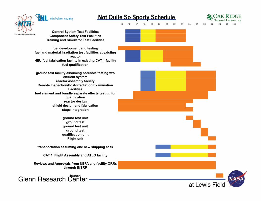
Notional NTP Ground & Flight Test Demonstration Milestone Schedule
: Planning : Preliminary Design : Final Design : Construction : Checkout
at Lewis Field Glenn Research Center
15 16 17 18 19 20 21 22 23 24 25 26 27 28 29 30
Control System Test Facilities
Component Safety Test Facilities
Training and Simulator Test Facilities
fuel development and testing
fuel and material Irradiation test facilities at existing
reactor
HEU fuel fabrication facility in existing CAT 1 facility
fuel qualification
ground test facility assuming borehole testing w/o
effluent system
reactor assembly facility
Remote Inspection/Post-Irradiation Examination
Facilities
fuel element and bundle separate effects testing for
qualification
reactor design
shield design and fabrication
stage integration
ground test unit
ground test
ground test unit
ground test
qualification unit
Flight unit
transportation assuming one new shipping cask
CAT 1 Flight Assembly and ATLO facility
Reviews and Approvals from NEPA and facility ORRs
through INSRP
launch
Not Quite So Sporty Schedule

at Lewis Field Glenn Research Center
• NASA, DOE (NE-75, ORNL, INL) and industry (Aerojet Rocketdyne) are working together on formulating a strategy leading to the development of a small GTD (~7.5 klbf) engine in the early 2020�s followed by a FTD mission using a small NTP stage (SNTPS) around 2025 • 10-years to a ground tested �qualification engine� by 2024 will require immediate, serious financial commitment along with a streamlined management and acquisition approach – DOE �• Graphite-based �composite fuel��is the baseline; an engine using this fuel type can be built sooner than one using another less established / less tested fuel at relevant conditions – DOE �• Testing should be conducted at the NTS using existing bore holes and/or tunnels; should maximize the use of existing facilities and consider temporary new facilities as required; new nuclear infra- structure is a long lead item – DOE �• If graphite-based fuel and borehole testing are not used, years of additional schedule and significant additional dollars will be required – DOE �• The FTD mission proposed by GRC is a single-burn �lunar flyby� mission to keep it simple and more affordable; small size engine and stage can also reduce development costs & allowing utilization of existing, flight proven engine hardware (e.g., hydrogen pumps and nozzles) – Aerojet Rocketdyne
If you want to go somewhere soon you need to get moving now - DOE
Summary and Conclusions


![Evolution of flight in animals · 2 Evolution of insect flight Several theories have been suggested for the origin of flight in insects (summarized in Thomas and Norberg [1])](https://img.pdfslide.us/doc/110x75/5f0850067e708231d4216393/evolution-of-iight-in-animals-2-evolution-of-insect-iight-several-theories-have.jpg)