Embed Size (px)
Citation preview

Affordable Design Techniques for Broadband DAS Expansion
Rand SkopasDir. of Field Sales

Agenda
• Challenges of frequency expansion in DAS systems• Directional couplers and signal tappers• DAS applications for directional couplers and signal
tappers• System integrator design approach using signal tappers
versus directional couplers• Cost comparison• Conclusion

Mobile Usage and Functionality Growth Drives…

…Mobile Traffic Growth, which Drives…

…Infrastructure Investment by Carriers…
Q4 2010: AT&T reportedly on track to roll out 4G LTE network in mid-2011 while upgrading 3G service. Faster speeds support current users and serve as a fallback during full 4G roll-out.

…and More Carrier Investment…
12/1/2010: Verizon Wireless announced it will launch the first large-scale LTE (4G) cellular network on December 5, bringing service to 38 metropolitan areas and 60 airports in the United States.

Industry Partnerships Drive More Growth
Q1: Apple announces release of Verizon-compatible iPhone4 for Feb 11, 2011.

DAS and Wireless Infrastructure Growth

Frequency Expansion Challenges in DAS
• Covering frequency extremes in a single system
• Economic factors that lead to compromised performance
• Performance trade-offs during the design stages
VS.
Signal TapperDirectional Coupler

Directional Couplers
• What directional couplers do
• Internal technology
• How they work
• Why they work for DAS applications
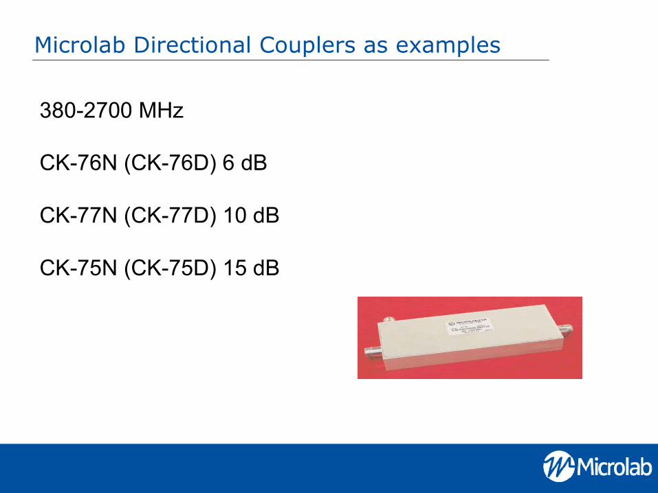
Microlab Directional Couplers as examples
380-2700 MHz
CK-76N (CK-76D) 6 dB
CK-77N (CK-77D) 10 dB
CK-75N (CK-75D) 15 dB

Introduction to Tappers
• What tappers do
• Technology (design approach)
• How they work
• Why they work for DAS applications

Tapper - Directional Coupler Comparison
• Directional couplers– Broadband (380-2700 MHz)– Low PIM/high power– High directivity, high isolation– RoHS compliant/IP65– Higher cost, similar coverage: up to 2.5 times the cost!
• Tappers– Ultra broadband (350-2700 MHz)– Lowest PIM/highest power– RoHS compliant/IP67– Low cost: Increased profit margin with no negative impact on system
performance!

Tappers: Typical vs. Microlab
Frequency bands: 800 – 2,500 MHz. 350 - 2,700 MHz
Loss: <0.3 dB max. (main line) 0.1 dB max. (main line)
Power: 100W avg., 3 kW peak 500W avg., 3 kW peak
Impedance: 50Ω nominal 50Ω nominal
PIM: Not applicable <-150 dBc
Environment: IP64, 0°C to +50°C IP67, -35°C to +75°C
Connectors: N(f) or 7/16 DIN (f) tri-metal plate: Same
Housing finish: passivated aluminum: Same
Weight, nom: <16 oz. (430 g) 14 oz. (380 g)

Microlab Signal Tappers (350-2700 MHz)
DN-34FN 2:1/3.0dB -1.8/-4.8
DN-44FN 3:1/4.8dB -1.3/-6.1
DN-54FN 4:1/6.0dB -1.0/-7.0
DN-64FN 6:1/8.0dB -0.7/-8.6
DN-74FN 10:1/10dB -0.4/-10.4
DN-84FN 20:1/13dB -0.2/-13.2
DN-94FN 30:1/15dB -0.1/-15.1
DN-04FN 100:1/20dB -0.1/-20.1
DN-14FN 1000:1/30dB -0.1/-30.1
*In range 350 - 380 MHz branch flatness is ±1.0
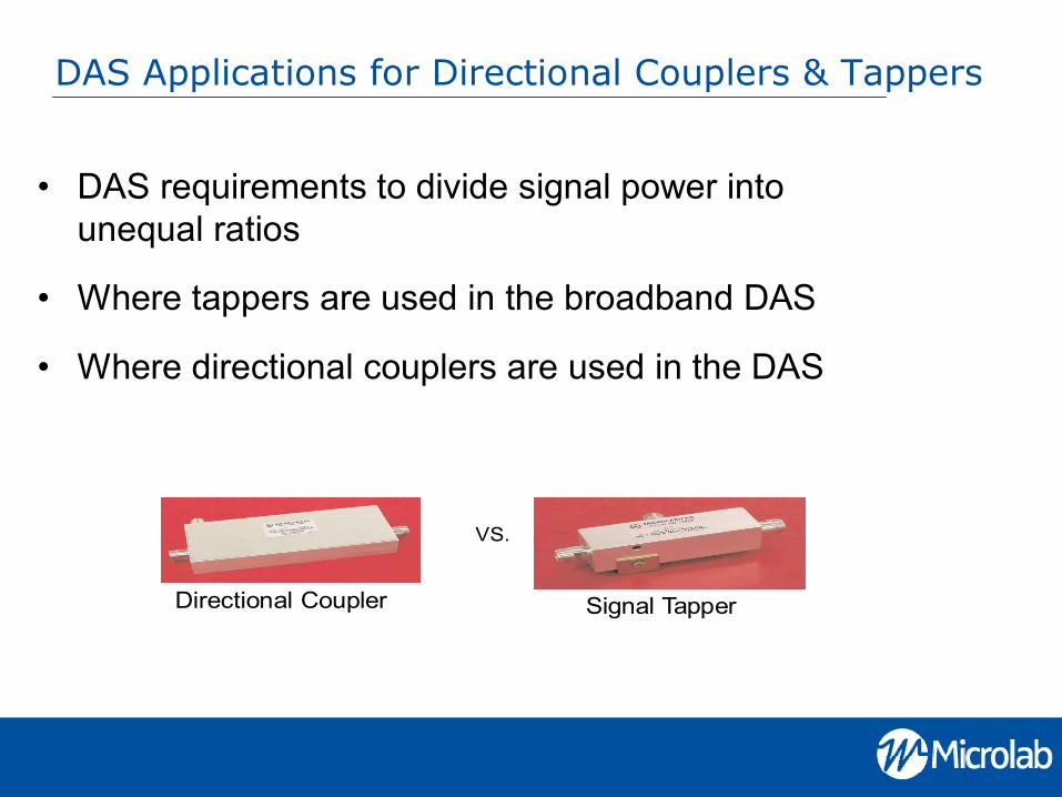
DAS Applications for Directional Couplers & Tappers
• DAS requirements to divide signal power into unequal ratios
• Where tappers are used in the broadband DAS
• Where directional couplers are used in the DAS
VS.
Signal TapperDirectional Coupler

System Design
• Compensation techniques to transition from directional couplers to signal tappers
• Simplifying the issues
• Implementing the changes
• Deploying the system

Directional Couplers in DAS

Value Comparison
• Frequency versus cost
• Cost of broad-band/future-proof
• Paying for PIM

Tapper Value Graph
Frequency
Cost
380 2700
DirectionalCoupler
Tapper
800 2500
As frequencies increase so doesthe value of the tapper

Microlab Directional Couplers
• Frequency range: 380 to 2700 MHz• VSWR, max: 1.20:1, all ports (1.30:1, >2500 MHz)• Power handling: 200W avg., 3 kW peak*• Directivity, min: 20dB, (18dB >2500 MHz)• Impedance: 50Ω nominal• Intermodulation, PIM: <-140 dBc with 2 tones• +43 dBm; <-150 dBc to order• Environment: -35°C to +75°C, IP64 (IP67 to order)• Housing finish: passivated aluminum• Connectors: triplate, female

Microlab Company Overview
• A Wireless Telecom Group company founded in 1949, designs and manufactures high-performance passive RF and microwave solutions, such as dividers, directional couplers, filters and integrated multi-carrier combiner systems
• Distinctive Component Characteristics:– Broadband – Low loss– Low PIM– Superior quality construction
• Our Solutions are used in:– Cell towers– Radio base stations– In-building DAS– Global transportation/communications systems– Homeland Security systems

Thanks for participating!
Any questions?
Please join us for our next webinar about:DLTS 7200 presented by Boonton Electronics

Next Steps to a Solution
Contact Microlab TODAYto discuss your system requirements
Rand Skopas+1 (973) 386-9696 ext. 3114
Danny Larsen+1 (973) 386-9696 ext. 3109
Tony Ramsden+1 (973) 386-9696 ext. 3111