Embed Size (px)
Citation preview

AFDXXX(X)AC Series
Installation and Service Manual
Please read this manual thoroughly before attempting to install and commission your water
maker.
E & O E
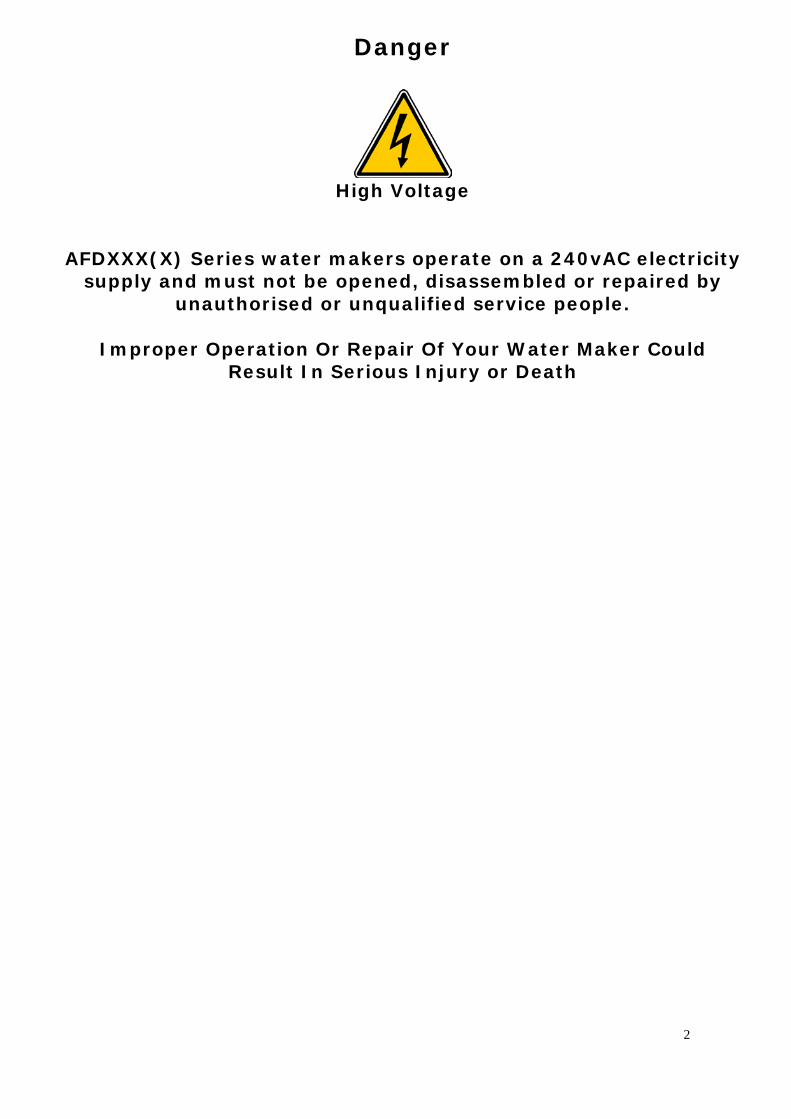
Danger
High Voltage
AFDXXX(X) Series water makers operate on a 240vAC electricity supply and must not be opened, disassembled or repaired by
unauthorised or unqualified service people.
Improper Operation Or Repair Of Your Water Maker Could Result In Serious Injury or Death
2
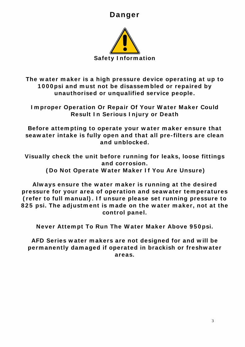
Danger
Safety Information
The water maker is a high pressure device operating at up to 1000psi and must not be disassembled or repaired by
unauthorised or unqualified service people.
Improper Operation Or Repair Of Your Water Maker Could Result In Serious Injury or Death
Before attempting to operate your water maker ensure that
seawater intake is fully open and that all pre-filters are clean and unblocked.
Visually check the unit before running for leaks, loose fittings
and corrosion. (Do Not Operate Water Maker If You Are Unsure)
Always ensure the water maker is running at the desired
pressure for your area of operation and seawater temperatures (refer to full manual). If unsure please set running pressure to 825 psi. The adjustment is made on the water maker, not at the
control panel.
Never Attempt To Run The Water Maker Above 950psi.
AFD Series water makers are not designed for and will be permanently damaged if operated in brackish or freshwater
areas.
3
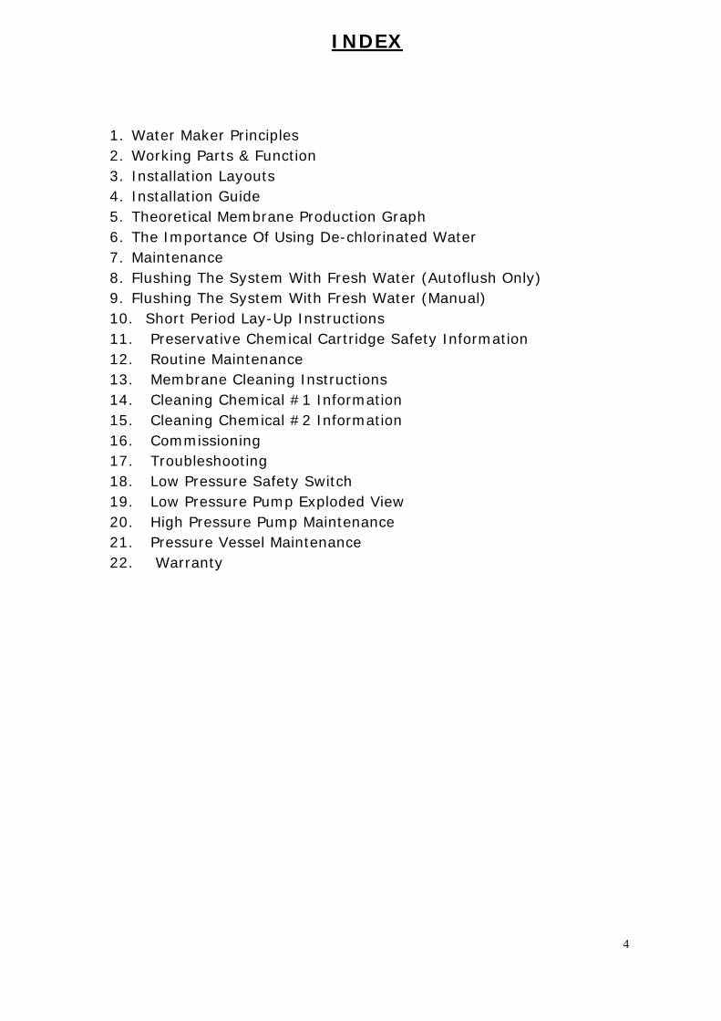
INDEX
1. Water Maker Principles 2. Working Parts & Function 3. Installation Layouts 4. Installation Guide 5. Theoretical Membrane Production Graph 6. The Importance Of Using De-chlorinated Water 7. Maintenance 8. Flushing The System With Fresh Water (Autoflush Only) 9. Flushing The System With Fresh Water (Manual) 10. Short Period Lay-Up Instructions 11. Preservative Chemical Cartridge Safety Information 12. Routine Maintenance 13. Membrane Cleaning Instructions 14. Cleaning Chemical #1 Information 15. Cleaning Chemical #2 Information 16. Commissioning 17. Troubleshooting 18. Low Pressure Safety Switch 19. Low Pressure Pump Exploded View 20. High Pressure Pump Maintenance 21. Pressure Vessel Maintenance 22. Warranty
4

Aquafresh Reverse Osmosis Water Maker
Installation and Service Manual
AFDXXX(X) Models
Owners and operators of Aquafresh water makers are urged to read this manual thoroughly as, by understanding the principles of osmosis, operational problems will be avoided and satisfaction with your unit will be realised.. All elements of the system are described in detail to give you a working knowledge of their function in order that minor defects may be overcome before they lead to major problems and expensive repairs or worse. Please read this manual through before attempting to install, connect or run the system.
5
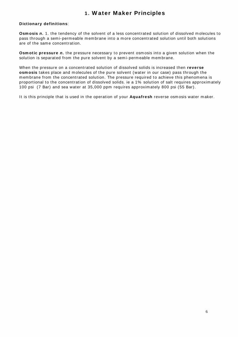
1. Water Maker Principles
Dictionary definitions: Osmosis n. 1. the tendency of the solvent of a less concentrated solution of dissolved molecules to pass through a semi-permeable membrane into a more concentrated solution until both solutions are of the same concentration. Osmotic pressure n. the pressure necessary to prevent osmosis into a given solution when the solution is separated from the pure solvent by a semi-permeable membrane. When the pressure on a concentrated solution of dissolved solids is increased then reverse osmosis takes place and molecules of the pure solvent (water in our case) pass through the membrane from the concentrated solution. The pressure required to achieve this phenomena is proportional to the concentration of dissolved solids. ie a 1% solution of salt requires approximately 100 psi (7 Bar) and sea water at 35,000 ppm requires approximately 800 psi (55 Bar). It is this principle that is used in the operation of your Aquafresh reverse osmosis water maker.
6
2.Working Parts and Function
Aquafresh AFD series Watermakers are AC powered units, they consist of the following main components: AC Driven Low Pressure (LP) Pump AC Driven High Pressure (HP) Pump AC Driven Main Panel inc. Processor Passive Prefilter Assembly (5 & 30 Micron) LCD Remote Digital Panel Optional Components: DC Driven Flush Valve (SAFI) Active Carbon Filter Assembly
System Function (Standard)
Sea Water Sea water is drawn into the system by the low pressure, centrifugal priming pump (LP Pump), via a 3/4 inch inlet sea cock, strainer and 'L' port valve. The other position on the 'L' port valve is a 1/2 inch 'SERVICE' connection for the intake of cleaning and disinfecting solutions, this connection may also be used to prime the LP Pump when necessary. The output of the LP Pump feeds the first (30 micron) of two system filters. A double filter system is then added where the condition of the filters may be seen through the transparent filter bowls or by reference to the low pressure gauge located on top. In service, the filters will darken from their natural white colour, becoming almost black when badly contaminated and in need of changing. From the second (5 micron) filter the sea water is fed at low pressure, of at least 3 psi, to the inlet manifold of a positive displacement, high pressure pump. This can create a pressure of up to 1400 psi, however, the pressure can be adjusted manually from 0 – 1000 psi but is capped at 1000 psi by a pressure relief safety valve and the excess sea water is discharged overboard via the salt water discharge port. The pressurised flow of sea water passes through the Reverse Osmosis Membranes (RO membranes), the number in the system being dependent upon system size, and is then discharged via the Pressure Regulating Valve and salt water discharge port. It is essential for a flow of salt water, proportional to its salinity, to pass over the membranes at the correct rate and pressure. The pressure regulating valve controls back pressure which can be adjusted up to 900 psi, depending on salinity and water temperature, and indicated on the high pressure gauge. The sea water is then discharged overboard via the salt water discharge port. Fresh Water The fresh water connections on the end of the RO membranes are interconnected and pass via the digital salinity sensor to a solenoid operated divert valve. Water which has been analysed by the digital sensor and logic controller is deemed satisfactory is then diverted to the ships tanks via the automatically controlled divert valve. Water flow that does not pass this test is diverted to salt water discharge circuit and sent back overboard. The salinity sensing circuitry of your AFD series water maker is fully automatic and temperature compensated to ensure accurate operation at all times in any region of the world.
7
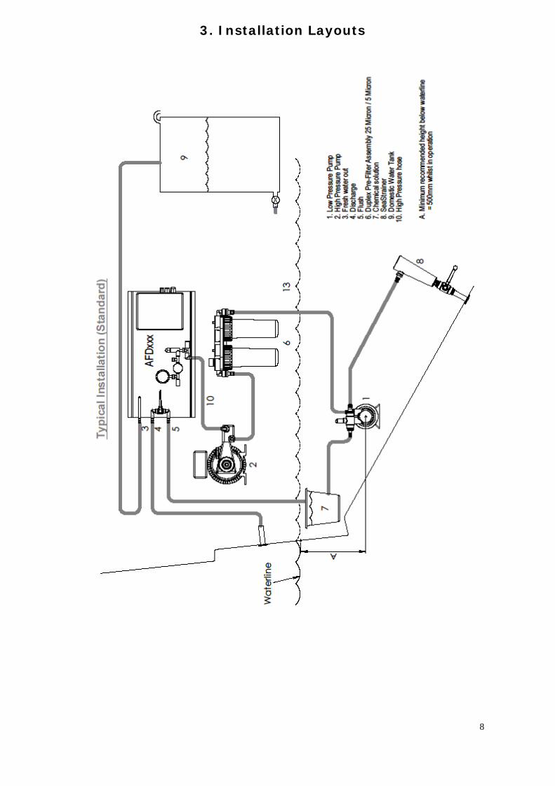
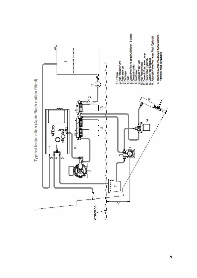
3. Installation Layouts
8
9
4 Installation Guide
Supplied Components
Main Panel High Pressure (HP) Pump Low Presurre (LP) Pump
Dual Pre-Filter Housings and Filters Remote Control Touchscreen
Remote Control Cable Installation Manual Operators Manual
OptionalComponents
Oil/Water Seperator Safi Valve
Check Valve Carbon Filter
Semi Automatic Flushing Pre-Filters
Power Requirements
The AFDXXXXAC Series watermakers use standard AC motors to power the LP and HP Pumps and as such consideration must be given to both running power requirements and
motor start inrush requirements.
Power requirements vary depending on the model of watermaker but running current will be stated on the specification sheet for your model.
Inrush current cannot be measured or calculated exactly but an inrush of 4-6 times the
running current is normal and can last from 250ms – 750ms. Your power source must be able to cope with this. Most conventional synchronous generators (3.5kW or greater) and
shore power systems are able to provide this power. Asynchronous generators or generators using inverter outputs will have to be sized accordingly as most cannot provide
more than their rated current even for a short period.
It is not recommended to run an AFDXXXXAC series watermaker on an inverter that cannot provide at least 6 times running current.
10

Installation Guide (Continued)
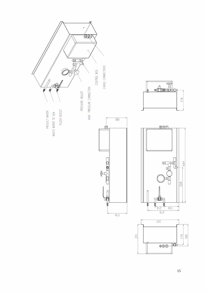
MAIN PANEL. The main panel unit is a heavy unit and as such must be mounted on a substantial structure or bulkhead, it must be mounted horizontally unless you have a bespoke version. No electrical equipment should be mounted beneath the main panel as spillage is likely to occur whilst winterising or servicing the unit. The system control box is mounted on the unit and is pre-wired with cables for power supply, LP Pump, HP Pump SAFI Valve and Remote Touchscreen. Each cable is identified by a label at the cable entry gland. Holes for mounting bolts are placed at the top and bottom edge of the panel.
11
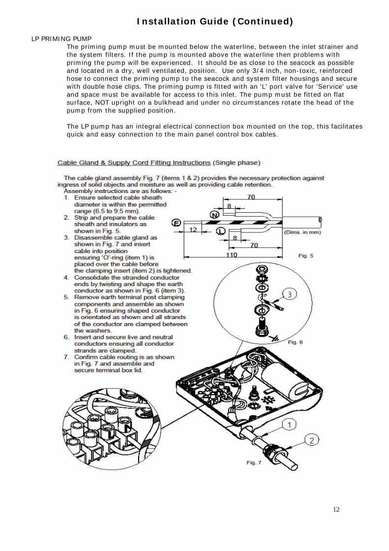
Installation Guide (Continued) LP PRIMING PUMP
The priming pump must be mounted below the waterline, between the inlet strainer and the system filters. If the pump is mounted above the waterline then problems with priming the pump will be experienced. It should be as close to the seacock as possible and located in a dry, well ventilated, position. Use only 3/4 inch, non-toxic, reinforced hose to connect the priming pump to the seacock and system filter housings and secure with double hose clips. The priming pump is fitted with an 'L' port valve for 'Service' use and space must be available for access to this inlet. The pump must be fitted on flat surface, NOT upright on a bulkhead and under no circumstances rotate the head of the pump from the supplied position. The LP pump has an integral electrical connection box mounted on the top, this facilitates quick and easy connection to the main panel control box cables.
12
HIGH PRESSURE PUMP
Using the anti vibration mounts supplied, fit the pump and motor on a level base, ensuring that the oil level in the pump will be horizontal. Ensure that there is adequate ventilation available to prevent the motor overheating, minimum 100mm space behind the motor fan. The crankcase will already be filled with the correct amount of oil. The HP pump must not be allowed to run dry as damage to the pump will occur. The HP pump is supplied with a short cable and junction box to facilitate easy connection the cable from the main panel control box cables.
Remove Label on Oil Filler Cap to ensure the breather hole in the oil cap is not covered.
SYSTEM FILTERS
Two filters are normally supplied; a 30 micron and 5 micron filter respectively from the priming pump. The filters should be mounted allowing adequate space for removal and replacement of the filter bowls. No electrical equipment should be mounted beneath the filters as spillage is likely to occur when changing the filter elements or cleaning the bowls. The low pressure gauge is fitted to the top of the filter system. If the optional Oil/Water separator is to be used, this should be installed after the micron filters.
Note: It is important that the hose connections between the sea cock and the LP pump and between the LP pump, System Filters and the HP pump run in a steady incline with no peaks or troughs that can cause air locks.
INLET.
A seacock and strainer of not less than 3/4 inch diameter is required, mounted as low in the bilge as possible to minimise the risk of surface debris and oil ingestion. The system should have its own inlet.. On no account should the inlet to the water maker be shared with any other system, e.g. engine, generator, toilet system or air conditioning etc.
Care should be taken to place inlet away from other system outlet such as grey water or sea toilet outlets.
Do not use any ferrous materials in the inlet system. On steel hulls change to non-ferrous fittings as soon as possible and ensure that the ferrous metal is painted to protect the water maker, as ferrous fouling will irreparably damage the membranes.
DISCHARGE. A discharge of at least 1/2 inch diameter, and which includes a shut-off valve, is required to be fitted at least 150mm (6 inches) above the waterline.
13
Installation Guide (Continued)
LOW PRESSURE PIPELINE CONNECTIONS.
Use good quality, reinforced, NON-TOXIC PVC hose. Ensure that hose will not flatten, either by adjacent objects or structures, or by having bends which are too tight. Clip all connections with stainless steel hose clips, double clipping all connections which are below the waterline.
HIGH PRESSURE CONNECTIONS.
Aquafresh Watermakers supply Cupro-Nickel High Pressure Pipe and/or Reinforced Flexible Pipe to connect the high pressure components of the system.
It is important to avoid the possibility of chafing, use pipe clips which have rubber sleeving. This also minimises the transmission of HP pump noise to the structure of the vessel.
FRESH WATER TANK CONNECTION.
Use only non-toxic pipe, connected to the storage tank in such a way that no back pressure will be caused by the vessels storage system.
Tanks must be fitted with a vent which discharges overboard when the tank is full. Venting into the bilge is not recommended as this may cause flooding.
When commissioning the unit all water produced during the first 20 minutes should be discharged overboard as the preservative used in the membranes can cause minor intestinal irritation.
SALT DISCHARGE.
Use suitable 1/2 inch reinforced, PVC hose. Ensure that the hose run cannot be kinked, as back pressure can cause damage to the system.
LCD TOUCHSCREEN REMOTE CONTROL.
This unit must be mounted in a dry position. A cable is provided with plugs at either end to enable simple connection to the main control box.
ELECTRICAL CONNECTIONS.
Observe polarity when making all connections. AC driven units use mains voltages, observe the same precautions.
Note. Attention should be made to the length of cable runs so that the voltage drop cannot affect correct operation of the system. Cable sizes of not less than 2.5mm are recommended. All cables should be clipped at regular intervals to prevent chafe.
Cable sizing should be in accordance with ABYC or RCD standards.
At the vessels distribution board circuit breakers for the system must be capable of carrying loads required to run the appropriate water making system used. Circuit breakers on vessels main distribution board should reflect the following:-
240 Volt 50Hz Single Phase systems 16 Amps
The above figures reflect maximum current at start-up, normal running requirements are lower.
Connection of the LP pump is straightforward with terminations marked clearly inside the motor cover and /or interconnection box.
The HP pump has a junction box fitted onto the lead. Simply observe AC wiring conventions
14
15
5. Theoretical Production Graph
16

17
6. The Importance of Using De-Chlorinated Water
Freshwater containing chlorine will damage your watermaker membranes.
When flushing or preserving your system, always use fresh
de-chlorinated water. This can be obtained by:
a) Running a freshwater hose through a carbon filter (available from Aquafresh Watermakers)
b) Using water already produced by your watermaker
c) Leaving an open bucket of fresh tap water to stand for 24
hours to allow the chlorine to evaporate. CAUTION: Chlorine damage to your membranes will invalidate the warranty.
18
7.Maintenance
The unexposed interiors of the RO membranes can promote algae growth in sea water and this can have the effect of reducing the output from the system. There is a greater risk of algae growth in warmer waters. If the unit is to be left unused for a period of 7 to 14 days, the system can be flushed with fresh de-chlorinated water to prevent fouling of the membranes. If the unit is to be left unused for a period greater than 14 days, up to a maximum of 3 months, there is a greater risk of fouling, which should be prevented using a Preservative cartridge, available from Aquafresh Watermakers. If the system is to be laid up where there is a possibility of freezing then the system MUST be filled with a special solution containing suitable glycol and disinfecting chemical. This is also available from Aquafresh Watermakers. NOTE: ON NO ACCOUNT MUST THE MEMBRANES BE ALLOWED TO BECOME DRY OR FREEZE, THIS WILL CAUSE IRREPARABLE DAMAGE.
19
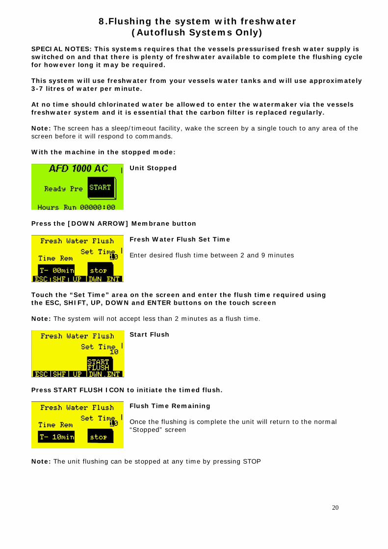
8.Flushing the system with freshwater (Autoflush Systems Only)
SPECIAL NOTES: This systems requires that the vessels pressurised fresh water supply is switched on and that there is plenty of freshwater available to complete the flushing cycle for however long it may be required. This system will use freshwater from your vessels water tanks and will use approximately 3-7 litres of water per minute. At no time should chlorinated water be allowed to enter the watermaker via the vessels freshwater system and it is essential that the carbon filter is replaced regularly. Note: The screen has a sleep/timeout facility, wake the screen by a single touch to any area of the screen before it will respond to commands. With the machine in the stopped mode:
Unit Stopped
Press the [DOWN ARROW] Membrane button
Fresh Water Flush Set Time Enter desired flush time between 2 and 9 minutes
Touch the “Set Time” area on the screen and enter the flush time required using the ESC, SHIFT, UP, DOWN and ENTER buttons on the touch screen Note: The system will not accept less than 2 minutes as a flush time.
Start Flush
Press START FLUSH ICON to initiate the timed flush.
Flush Time Remaining Once the flushing is complete the unit will return to the normal “Stopped” screen
Note: The unit flushing can be stopped at any time by pressing STOP
20
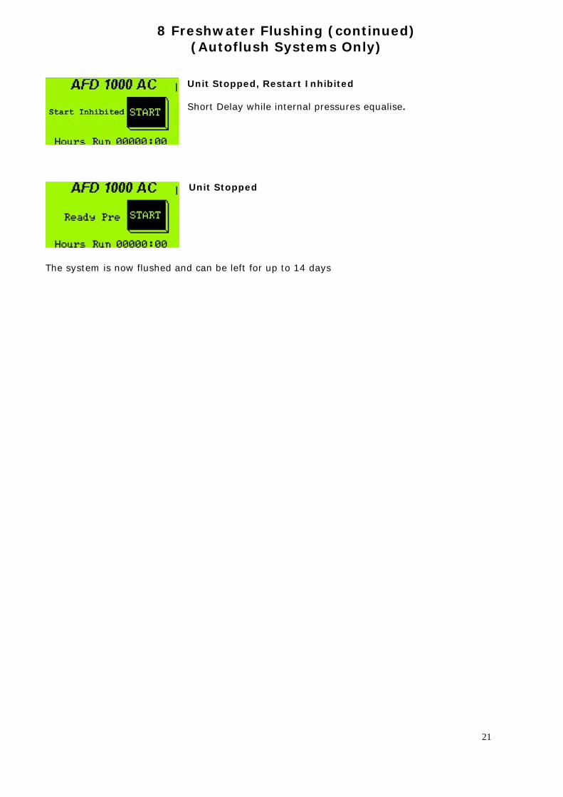
8 Freshwater Flushing (continued) (Autoflush Systems Only)
Unit Stopped, Restart Inhibited Short Delay while internal pressures equalise.
Unit Stopped
The system is now flushed and can be left for up to 14 days
21
9.Flushing the system with freshwater (Manual Systems)
Note: Use either water produced by your Aquafresh watermaker or water that has been passed
through a carbon filter. This operation will require a large bucket and around 15 litres of fresh de-chlorinated water
and some ½ inch hose
1. Connect a plastic 1/2 inch hose to the input 'L' port valve of the LP Pump and fill with water so that no air remains in the pipe. Then holding your thumb over the end of the pipe place the end of the hose into a bucket of fresh de-chlorinated water. Do NOT open the valve at this stage
2. Connect a 1/2 inch hose to the sea water output 'FLUSH' port on the 'L' port valve situated on the unit at the left hand side and lead the hose to the bucket containing the fresh de-chlorinated water. Do NOT open this valve to allow flow via the container as it is necessary to flush the water already in the system overboard first, done at the next stage.
3. Depress the 'SERVICE' switch on the side of the main electrical control box, noting that the LP pump runs. Open the input 'L' port valve on the LP PUMP and allow approximately 1/3 of the freshwater to discharge overboard before opening the output 'FLUSH’ on the ‘ L' port valve to circulate the fresh water through the system for 10 minutes. After 10 minutes, close the output Flush 'L' port valve to “SALT DISCHARGE” and allow all but the last drop of freshwater to discharge overboard before switching off the 'SERVICE' switch.
4. Close the inlet and discharge seacocks then close inlet ‘L’ port valve on the LP pump.
5. The system is now flushed and can be left for up to 14 days.
NOTE: Owners of AutoFlush systems can also use this method if preferred.
22
10. Short Period Lay-Up (Maximum up to 3 months). (Manual and Autoflush systems)
Note: This procedure must not be carried out with either organic or inorganic cleaner in the
system. Flush with fresh de-chlorinated water prior to treatment. Use either water produced by your Aquafresh Watermaker or water that has been passed through a carbon filter.
WARNING: This procedure uses Sodium Metabisulphite. Spills and splashed areas should be treated immediately with copious volumes of fresh
water. Irritation will be caused to the eyes, by inhalation and by ingestion. Wash skin with soap & water. Irrigate eyes with water and obtain medical advice. If inhaled, blow nose and wash nasal passages, obtain medical advice. If ingested, rinse out mouth. Give water to drink, seek medical advice. If large amounts of this fluid are ingested then induce vomiting, seek medical advice.
1. Connect a plastic 1/2 inch hose to the input 'L' port valve of the LP pump and fill with water so that no air remains in the pipe. Then holding your thumb over the end of the pipe place the end of the hose into a bucket of fresh de-chlorinated water. Do NOT open the valve at this stage..
2. Connect a 1/2 inch hose to the sea water output 'FLUSH' on the 'L' port valve situated on the
unit at the left hand side and lead the hose to the bucket containing the fresh dechlorinated water. Do NOT open this valve to allow flow via the container as it is necessary to flush the water already in the system overboard first, done at the next stage. Remove both of the filters from their bowls and screw back into place.
3. Depress the 'SERVICE' switch on the main electrical control box, noting that the LP pump
runs. Open the input 'L' port valve on the LP PUMP and allow approximately 1/3 of the freshwater to discharge overboard before opening the output 'FLUSH’ on the ‘ L' port valve to circulate the fresh water through the system for a further 10 minutes. After 10 minutes, close the output Flush 'L' port valve to “SALT DISCHARGE” and allow all but the last drop of freshwater to discharge overboard before switching off the 'SERVICE' switch.
4. Place the Preservative cartridge (Green) into either filter housing and screw into place. Refill
the bucket with fresh dechlorinated water.
5. Press the service switch to start the Priming pump. Let the pump run for 30 minutes, allowing the Preserving chemical to circulate fully.
6. After 30 minutes, depress the ‘SERVICE’ switch, the LP pump should stop.
7. Close the inlet and discharge seacocks then close inlet 'L' port valve on the LP pump. The
system will now be full of the Preserving solution. Remove the 1/2 inch hoses and discard any chemical solution that remains, flushing away with copious amounts of water.
8. The suggested time for the unit to be stored is for up to 3 months after the use of this
cartridge. If the unit will sit for more than 3 months, repeat this procedure every 3 months.
9. When using the watermaker again follow the de-winterising procedure in the operations manual
23
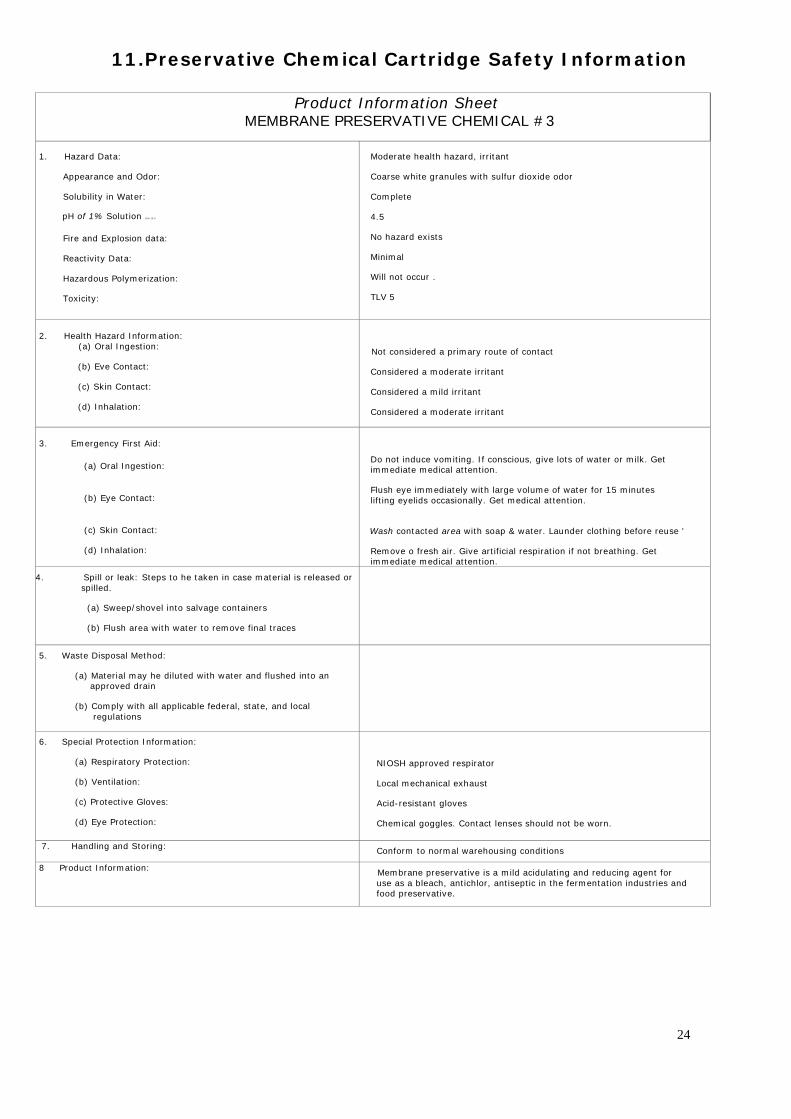
11.Preservative Chemical Cartridge Safety Information
Product Information Sheet
MEMBRANE PRESERVATIVE CHEMICAL #3
1. Hazard Data:
Appearance and Odor:
Solubility in Water:
pH of 1% Solution CS% 20"C:
Fire and Explosion data:
Reactivity Data:
Hazardous Polymerization:
Toxicity:
Moderate health hazard, irritant
Coarse white granules with sulfur dioxide odor
Complete
4.5
No hazard exists
Minimal
Will not occur .
TLV 5
2. Health Hazard Information: (a) Oral Ingestion:
(b) Eve Contact:
(c) Skin Contact:
(d) Inhalation:
Not considered a primary route of contact
Considered a moderate irritant
Considered a mild irritant
Considered a moderate irritant
3. Emergency First Aid:
(a) Oral Ingestion:
(b) Eye Contact:
(c) Skin Contact:
(d) Inhalation:
Do not induce vomiting. If conscious, give lots of water or milk. Get immediate medical attention.
Flush eye immediately with large volume of water for 15 minutes lifting eyelids occasionally. Get medical attention.
Wash contacted area with soap & water. Launder clothing before reuse '
Remove o fresh air. Give artificial respiration if not breathing. Get immediate medical attention.
4. Spill or leak: Steps to he taken in case material is released or spilled.
(a) Sweep/shovel into salvage containers
(b) Flush area with water to remove final traces
5. Waste Disposal Method:
(a) Material may he diluted with water and flushed into an approved drain
(b) Comply with all applicable federal, state, and local regulations
6. Special Protection Information:
(a) Respiratory Protection:
(b) Ventilation:
(c) Protective Gloves:
(d) Eye Protection:
NIOSH approved respirator
Local mechanical exhaust
Acid-resistant gloves
Chemical goggles. Contact lenses should not be worn.
7. Handling and Storing: Conform to normal warehousing conditions
8 Product Information: Membrane preservative is a mild acidulating and reducing agent for use as a bleach, antichlor, antiseptic in the fermentation industries and food preservative.
24
12.Routine Maintenance Daily checks Check running hours of system for any routine maintenance which may be due. Check system sea water strainer for debris and clean as required. Visually inspect system for leaks and take remedial action as necessary. Visually inspect the high pressure flexible pipe for chafe or 'bulging'. Replace if defective. If
‘bulging’ is seen do NOT run the water maker as a high pressure burst may occur. Contact Aquafresh Watermakers for replacement.
Check HP pump oil level and top up if required. Check condition of both system micron pre-filters. If badly discoloured , replace them. Under normal use offshore you can expect 100 hours or
more use, unless plankton or sediment is prevalent. When replacing filters, always clean the clear filter bowls. DO NOT use a detergent, as this could contaminate the RO membranes. If the filter bowls are opened then you MUST bleed any air from the system by operating the 'SERVICE' switch and depressing the bleed vents on top of the filter bowls, only then operate the normal on/off switch which will allow the HP pump to function.
DO NOT ATTEMPT TO BLEED THE SYSTEM WITH THE HP PUMP RUNNING. Periodic Maintenance First 50 hours: Change HP pump oil. Every 500 hours or annually. Change HP pump oil Lubricant types: Approved 'CAT' pump oils. CAT High Viscosity Index Hydraulic Crankcase Oil Obtainable from Aquafresh Watermakers. OR BP Energol HLP 150 Esso Neuto 150 Texaco Regal ARNO 150 Castrol Hyspin ANS 150 Shell Tellus 150 Use only high quality hydraulic oil which is non-foaming and non-detergent. Do NOT use engine oil.
25
13.Membrane Cleaning After Long Term Use Using Single Use Cleaning Cartridges
DO NOT REMOVE REVERSE OSMOSIS ELEMENTS FROM THEIR HOUSINGS UNDER ANY CIRCUMSTANCES. Under normal operation the RO membranes can be fouled by mineral scale, dirt and biological matter. Deposits can build up over a period of time causing lower output of fresh water and/or lack of salt rejection. The system should be cleaned when the output of fresh water drops by more than 15% from the flow rate determined at time of commissioning. The output figure should however be adjusted for any temperature difference by reference to the Theoretical Membrane Output graph. WARNING. Caustic and acid solutions are used in the cleaning procedures and great care should be taken when handling. Rubber gloves and protective clothing should be worn. Spills and splashed areas should be treated immediately with copious volumes of fresh water. Irritation will be caused to the eyes, by inhalation and by ingestion. Wash skin with soap & water. Irrigate eyes with water for at least 15 minutes and obtain medical advice. If inhaled, blow nose and wash nasal passages, obtain medical advice. If ingested, rinse out mouth. Give water to drink, seek medical advice. If large amounts of this fluid are ingested then induce vomiting, seek medical advice. When flushing the unit always use Fresh De-chlorinated Water. Do NOT carry out the following treatments if Sodium Metabisulphite is in the system, first flush the system with fresh de-chlorinated water. Procedure Membrane Cleaning for Organics & Particulates. These cleaning cartridges contain irritants. Avoid contact with skin, eyes and clothing. Do not inhale dust. Refer to relevant Health and Safety Data Sheet.
1. Connect a 1/2 inch hose to the input 'L' port valve on the priming pump and fill the pipe with water before placing your thumb over the end and placing the hose end into a bucket of fresh de-chlorinated water. Do NOT open the valve to this inlet at this stage.
2. Connect a 1/2 inch hose to the output FLUSH 'L' port valve placing the hose end into the
Freshwater. Do NOT open the valve to this inlet.
3. Remove the filters from their bowls, clean (DO NOT use detergent) and replace the now empty bowls
4. Press the ‘SERVICE’ switch. Open the 'L' port valve on the LP pump to allow Freshwater to
enter the system and allow approximately 1/3 of the freshwater to discharge overboard before opening the output flush 'L' port valve. Allow the unit to be flushed for approximately 10 minutes.
5. Adjust the pressure regulating valve to show a pressure of no more than 80 psi. No product
water should be produced.
a. Note: During this process ensure that the level of liquid in the container is maintained above the 1/2 inch hose connected to the input 'L' port valve on the LP pump.
6. After 10 minutes, depress the ‘SERVICE’ switch to stop the Priming pump running.
26
Membrane Cleaning After Long Term Use Using Single Use Cleaning Cartridges (Continued)
7. Place cleaning filter #1 (BLUE) into either filter housing and screw into place. Press the
‘SERVICE’ switch to start the Priming pump.
8. Let the pump run for 30 minutes to allow the chemical to circulate.
9. After 30 minutes, depress the ‘SERVICE’ switch, the LP pump will stop. Remove the cleaning filter and screw empty housing back into place. Empty the bucket of chemical solution and refill with Fresh de-chlorinated water. Press the ‘SERVICE switch and Flush the unit for 5 minutes. Press ‘SERVICE’ switch, the LP pump will stop.
10. Refill the bucket with Fresh de-chlorinated water then return to step 7. This time using the
RED cartridge, carry out steps 7, 8 and 9 then go to step 11.
a. Note: b. It is essential that both organic and inorganic cleaning procedures are
carried out at the same time.
11. To return the unit to normal operation return the 'L' port valves to their normal position and remove the 1/2 inch hoses. Rotate the 'SALINITY' control fully anti-clockwise, passed the click-stop, to discharge any product water overboard and/or disconnect the product water feed to the vessels tanks.
12. Place new micron filters into their appropriate housings.
13. Using the 'SERVICE' switch to start the LP pump, bleed the system by depressing the buttons
situated on top of the filter housings. On completion switch off using the 'SERVICE' switch.
10. Restart the watermaker and run the de-winterising procedure TWICE, this is shown in the operations manual
27
14. Cleaning Chemical #1 Blue Information
Product Information Sheet CLEANING CHEMICAL #1 (BLUE)
1. Hazardous Material:
Active Ingredient:
Hazard Data (Threshold Limit Value (TLV), Lethal Dosage (LD50),
Lethal Concentration (LC50):
Appearance and Odor:
Solubility in Water:
pH of 2.4% Solution:
Fire and Explosion data:
Reactivity Data:
Incompatibility:
Hazardous Polymerization:
Toxicity:
Mixture contains no hazardous materials
Phosphates/organic acids
None
White Powder, odorless
Complete
l1+/-0.5
No hazard exists
Stabile
Avoid contact with aluminum
Will not occur
No TLVs have been established for this mixture
2. Health Hazard Information:
(a) Oral Ingestion:
(b) Eye Contact
(c) Skin Contact:
(d) Inhalation:
Not considered a primary route of contact
Considered a moderate irritant
Considered a mild irritant
Not considered a primary route of contact
3. Emergency First Aid:
(a) Oral Ingestion:
(b) Eye Contact:
(c) Skin Contact:
(d) Inhalation:
Not applicable
Flush eye immediately with large volume of water. Get medical attention.
Flush contacted area with water. Launder clothing before reuse.
Not applicable
4. Spill or leak: Steps to be taken in case material is released or
spilled.
(a) Vacuum or sweep/shovel into salvage containers
(b) Flush area with water to remove final traces
5. Waste Disposal Method:
(a) Material may be diluted with water and flushed into an
approved drain
(b) Comply with all applicable federal, state, and local
regulations
6. Special Protection Information:
(a) Respiratory Protection:
(b) Ventilation:
(c) Protective Gloves:
(d) Eye Protection:
None required
None required
Standard work gloves
Safety glasses
7. Handling and Storing: Conform to normal warehousing conditions
8. Product Information:
Alkaline detergent is a powder cleaner specifically designed for the
removal of organics, silt and other particulate deposits from polyamide
membrane surfaces.
28
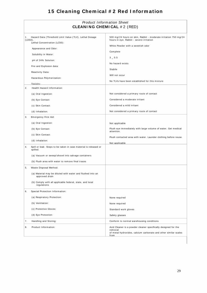
15 Cleaning Chemical #2 Red Information
Product Information Sheet CLEANING CHEMICAL #2 (RED)
1. Hazard Data (Threshold Limit Value (TLV), Lethal Dosage (LD50),
Lethal Concentration (LC50):
Appearance and Odor:
Solubility in Water:
pH of 24% Solution:
Fire and Explosion data:
Reactivity Data:
Hazardous Polymerization:
Toxicity:
500 mg/24 hours on skin, Rabbit - moderate irritation 750 mg/24 hours in eye. Rabbit - severe irritation
White Powder with a sweetish odor
Complete
3 _ 0.5
No hazard exists
Stabile
Will not occur
No TLVs have been established for this mixture
2. Health Hazard Information:
(a) Oral Ingestion:
(b) Eye Contact:
(c) Skin Contact:
(d) Inhalation:
Not considered a primary route of contact
Considered a moderate irritant
Considered a mild irritant
Not considered a primary route of contact
3. Emergency First Aid:
(a) Oral Ingestion:
(b) Eye Contact:
(c) Skin Contact:
(d) Inhalation:
Not applicable
Flush eye immediately with large volume of water. Get medical attention.
Flush contacted area with water. Launder clothing before reuse.
Not applicable 4. Spill or leak: Steps to be taken in case material is released or
spilled.
(a) Vacuum or sweep/shovel into salvage containers
(b) Flush area with water to remove final traces
5. Waste Disposal Method:
(a) Material may be diluted with water and flushed into an approved drain
(b) Comply with all applicable federal, state, and local regulations
6. Special Protection Information:
(a) Respiratory Protection:
(b) Ventilation:
(c) Protective Gloves:
(d) Eye Protection:
None required
None required
Standard work gloves
Safety glasses
7. Handling and Storing: Conform to normal warehousing conditions
8. Product Information: Acid Cleaner is a powder cleaner specifically designed for the removal of metal hydroxides, calcium carbonate and other similar scales from
29
16.Commissioning
On completion of equipment installation, plumbing and electrical connection the system can be commissioned using the following procedure.
1. Open inlet and outlet seacocks, manually bleeding the system, starting from the inlet end. It may be necessary to bleed the low pressure pump. Inspect all connections below waterline for obvious leaks.
2. Switch on power to the system at the vessels distribution board.
3. The remote LCD panel should power up
4. Fully open the pressure regulating valve.
5. Switch the 'SERVICE' switch located on the watermaker control box to ON. This will operate
only the LP pump.
6. Bleed ALL air from the filters by depressing the buttons situated on top of each of the filter housings. Ensure that water is being discharged from the hull fitting and that no air is seen bubbling inside the filter housings. Should the pressure regulating valve be closed then discharge overboard will not occur.
7. Press the SERVICE switch to STOP the LP pump.
8. From the remote LCD control panel run the de-winterising procedure, this procedure is shown
in the operations manual. This is a 20 minute programme. Ensure operating pressure is set to zero.
9. Once complete run the de-winterise programme for a 2nd time, only this time raise the operating pressure to 825 psi.
10. Inspect system for leaks, taking remedial action as necessary. Pay particular attention to any leaks around the vessel end caps as these can be easily damaged. Call Aquafresh if in any doubt
11. From control panel start the watermaker using the normal start procedure shown in the operations guide.
12. Your Aquafresh AFD series is fully automated at this point and will start to produce high
quality water within a few minutes. You can then fine tune the operating pressure in accordance with your local seawater temperatures and salinity, however 825-875 psi will work fine in nearly all areas. PLEASE NOTE THE AFD SERIES IS NOT FOR USE IN FRESHWATER OR BRACKISH WATER ENVIROMENTS
30
Troubleshooting, Repair &
Service Information
For Your Aquafresh Watermaker
31
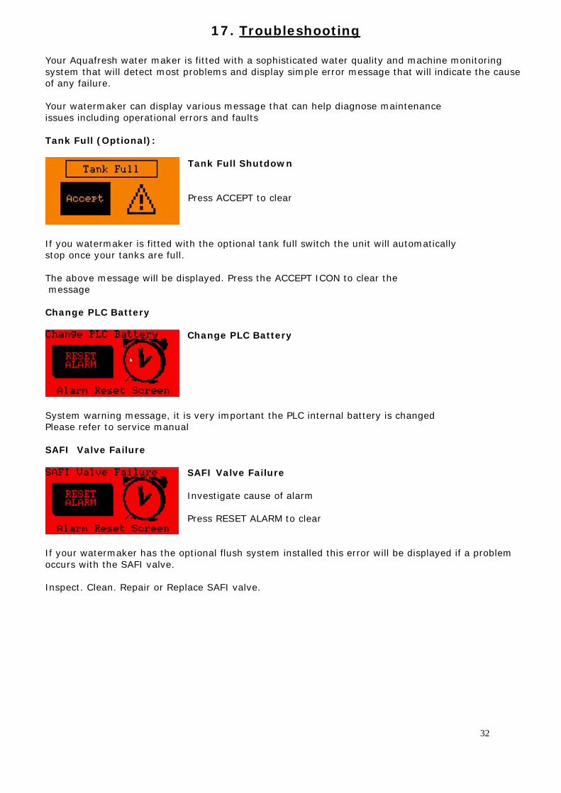
17. Troubleshooting
Your Aquafresh water maker is fitted with a sophisticated water quality and machine monitoring system that will detect most problems and display simple error message that will indicate the cause of any failure. Your watermaker can display various message that can help diagnose maintenance issues including operational errors and faults Tank Full (Optional):
Tank Full Shutdown Press ACCEPT to clear
If you watermaker is fitted with the optional tank full switch the unit will automatically stop once your tanks are full. The above message will be displayed. Press the ACCEPT ICON to clear the message Change PLC Battery
Change PLC Battery
System warning message, it is very important the PLC internal battery is changed Please refer to service manual SAFI Valve Failure
SAFI Valve Failure Investigate cause of alarm Press RESET ALARM to clear
If your watermaker has the optional flush system installed this error will be displayed if a problem occurs with the SAFI valve. Inspect. Clean. Repair or Replace SAFI valve.
32
Troubleshooting (continued)
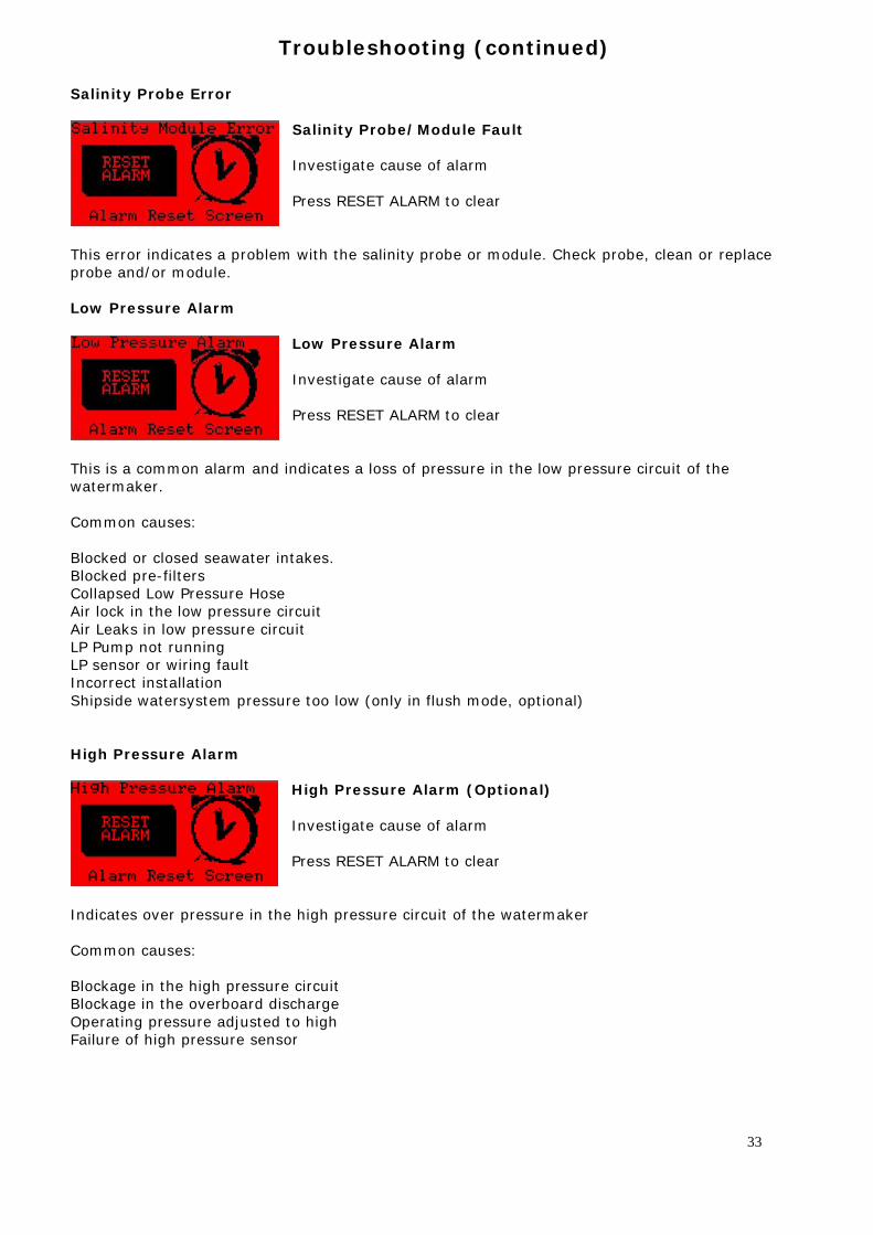
Salinity Probe Error
Salinity Probe/Module Fault Investigate cause of alarm Press RESET ALARM to clear
This error indicates a problem with the salinity probe or module. Check probe, clean or replace probe and/or module. Low Pressure Alarm
Low Pressure Alarm Investigate cause of alarm Press RESET ALARM to clear
This is a common alarm and indicates a loss of pressure in the low pressure circuit of the watermaker. Common causes: Blocked or closed seawater intakes. Blocked pre-filters Collapsed Low Pressure Hose Air lock in the low pressure circuit Air Leaks in low pressure circuit LP Pump not running LP sensor or wiring fault Incorrect installation Shipside watersystem pressure too low (only in flush mode, optional) High Pressure Alarm
High Pressure Alarm (Optional) Investigate cause of alarm Press RESET ALARM to clear
Indicates over pressure in the high pressure circuit of the watermaker Common causes: Blockage in the high pressure circuit Blockage in the overboard discharge Operating pressure adjusted to high Failure of high pressure sensor
33
Troubleshooting (continued)
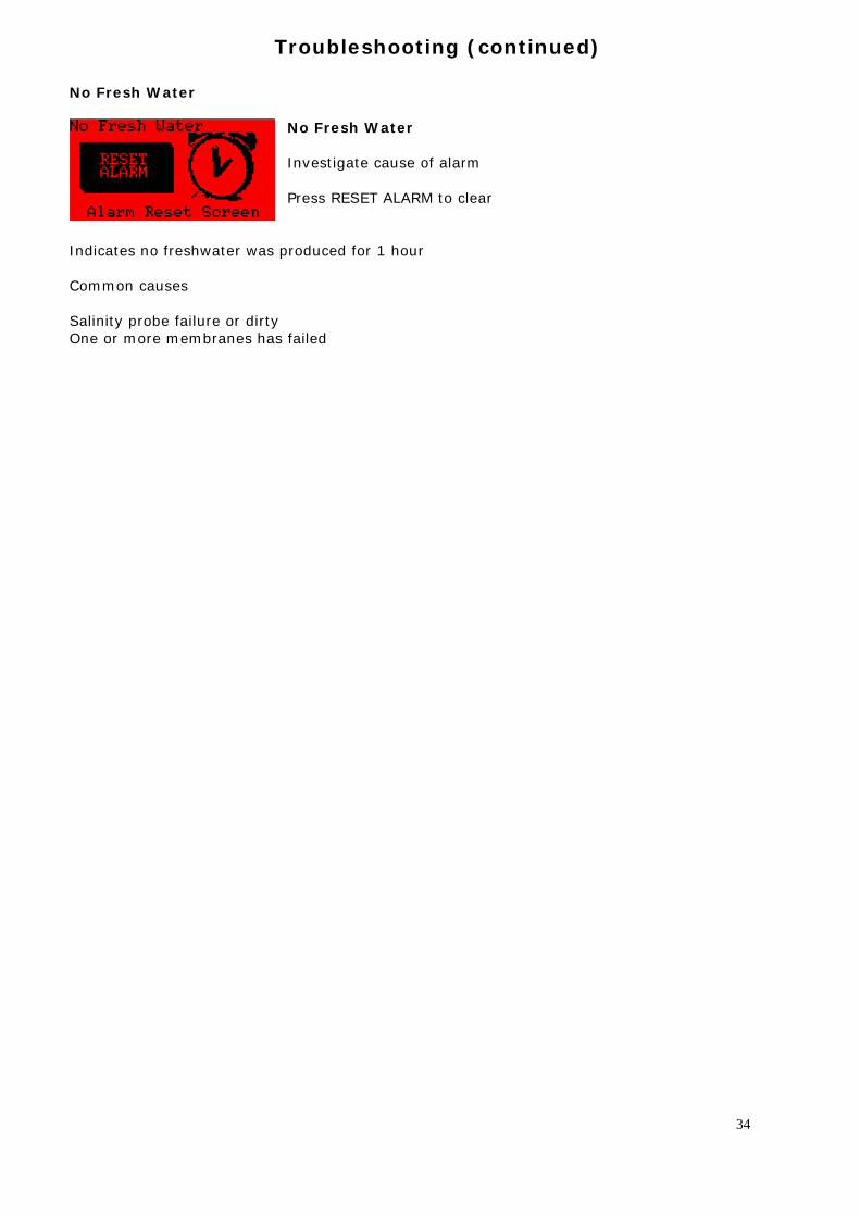
No Fresh Water
No Fresh Water Investigate cause of alarm Press RESET ALARM to clear
Indicates no freshwater was produced for 1 hour Common causes Salinity probe failure or dirty One or more membranes has failed
34
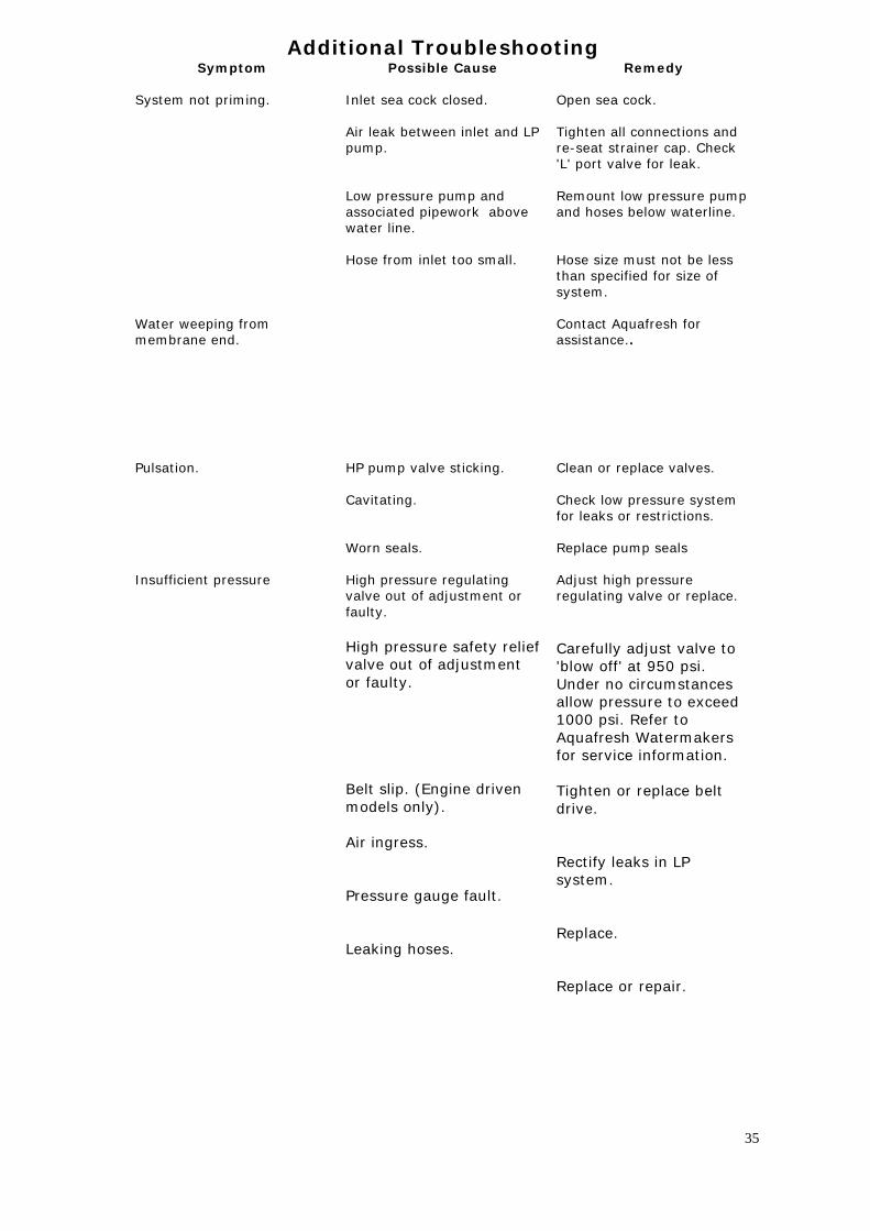
Additional Troubleshooting Symptom
System not priming. Water weeping from membrane end. Pulsation. Insufficient pressure
Possible Cause Inlet sea cock closed. Air leak between inlet and LP pump. Low pressure pump and associated pipework above water line. Hose from inlet too small. HP pump valve sticking. Cavitating. Worn seals. High pressure regulating valve out of adjustment or faulty. High pressure safety relief valve out of adjustment or faulty. Belt slip. (Engine driven models only). Air ingress. Pressure gauge fault. Leaking hoses.
Remedy Open sea cock. Tighten all connections and re-seat strainer cap. Check 'L' port valve for leak. Remount low pressure pump and hoses below waterline. Hose size must not be less than specified for size of system. Contact Aquafresh for assistance.. Clean or replace valves. Check low pressure system for leaks or restrictions. Replace pump seals Adjust high pressure regulating valve or replace. Carefully adjust valve to 'blow off' at 950 psi. Under no circumstances allow pressure to exceed 1000 psi. Refer to Aquafresh Watermakers for service information. Tighten or replace belt drive. Rectify leaks in LP system. Replace. Replace or repair.
35
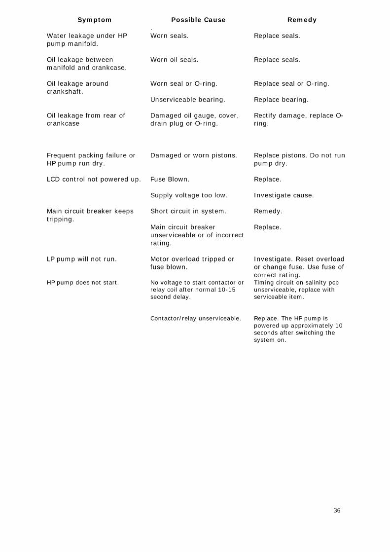
Symptom Water leakage under HP pump manifold. Oil leakage between manifold and crankcase. Oil leakage around crankshaft. Oil leakage from rear of crankcase Frequent packing failure or HP pump run dry. LCD control not powered up. Main circuit breaker keeps tripping. LP pump will not run. HP pump does not start.
Possible Cause . Worn seals. Worn oil seals. Worn seal or O-ring. Unserviceable bearing. Damaged oil gauge, cover, drain plug or O-ring. Damaged or worn pistons. Fuse Blown. Supply voltage too low. Short circuit in system. Main circuit breaker unserviceable or of incorrect rating. Motor overload tripped or fuse blown. No voltage to start contactor or relay coil after normal 10-15 second delay. Contactor/relay unserviceable.
Remedy Replace seals. Replace seals. Replace seal or O-ring. Replace bearing. Rectify damage, replace O-ring. Replace pistons. Do not run pump dry. Replace. Investigate cause. Remedy. Replace. Investigate. Reset overload or change fuse. Use fuse of correct rating. Timing circuit on salinity pcb unserviceable, replace with serviceable item. Replace. The HP pump is powered up approximately 10 seconds after switching the system on.
36
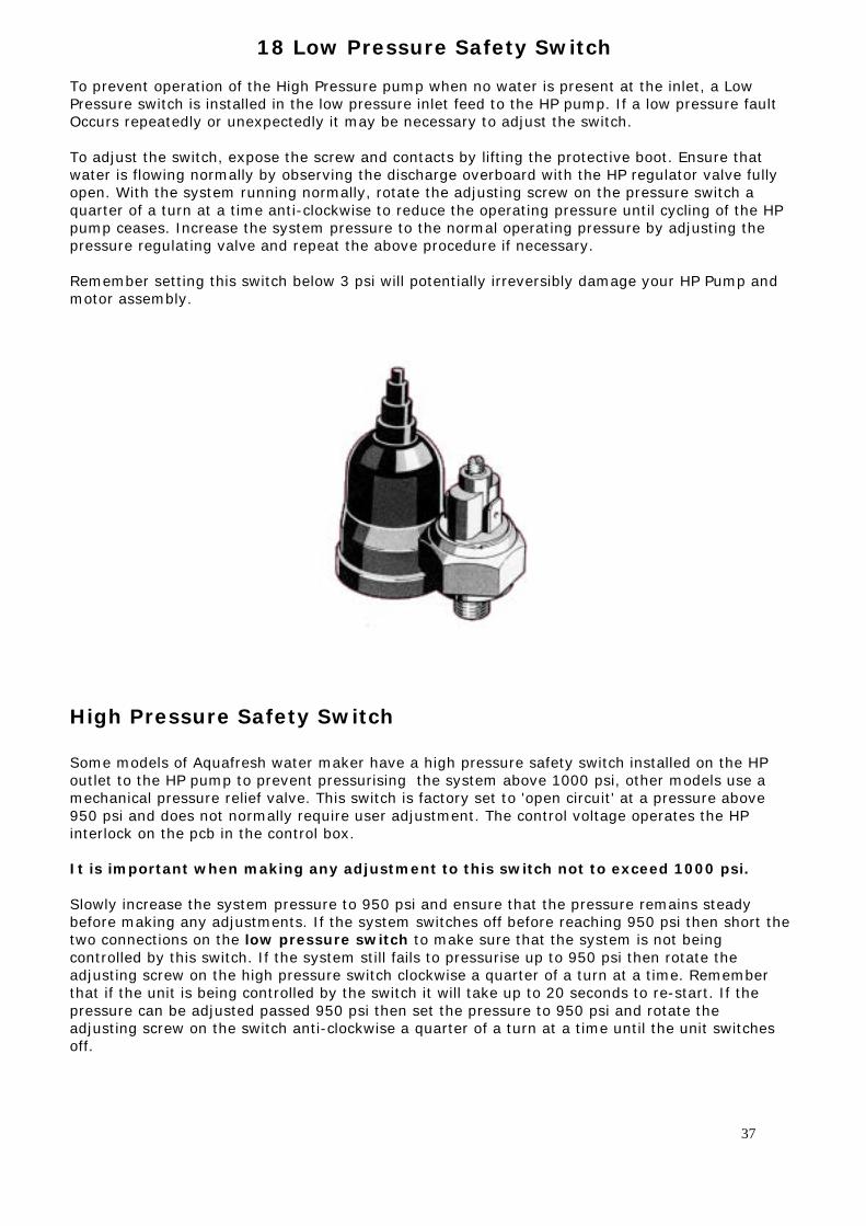
18 Low Pressure Safety Switch To prevent operation of the High Pressure pump when no water is present at the inlet, a Low Pressure switch is installed in the low pressure inlet feed to the HP pump. If a low pressure fault Occurs repeatedly or unexpectedly it may be necessary to adjust the switch. To adjust the switch, expose the screw and contacts by lifting the protective boot. Ensure that water is flowing normally by observing the discharge overboard with the HP regulator valve fully open. With the system running normally, rotate the adjusting screw on the pressure switch a quarter of a turn at a time anti-clockwise to reduce the operating pressure until cycling of the HP pump ceases. Increase the system pressure to the normal operating pressure by adjusting the pressure regulating valve and repeat the above procedure if necessary. Remember setting this switch below 3 psi will potentially irreversibly damage your HP Pump and motor assembly.
High Pressure Safety Switch Some models of Aquafresh water maker have a high pressure safety switch installed on the HP outlet to the HP pump to prevent pressurising the system above 1000 psi, other models use a mechanical pressure relief valve. This switch is factory set to 'open circuit' at a pressure above 950 psi and does not normally require user adjustment. The control voltage operates the HP interlock on the pcb in the control box. It is important when making any adjustment to this switch not to exceed 1000 psi. Slowly increase the system pressure to 950 psi and ensure that the pressure remains steady before making any adjustments. If the system switches off before reaching 950 psi then short the two connections on the low pressure switch to make sure that the system is not being controlled by this switch. If the system still fails to pressurise up to 950 psi then rotate the adjusting screw on the high pressure switch clockwise a quarter of a turn at a time. Remember that if the unit is being controlled by the switch it will take up to 20 seconds to re-start. If the pressure can be adjusted passed 950 psi then set the pressure to 950 psi and rotate the adjusting screw on the switch anti-clockwise a quarter of a turn at a time until the unit switches off.
37
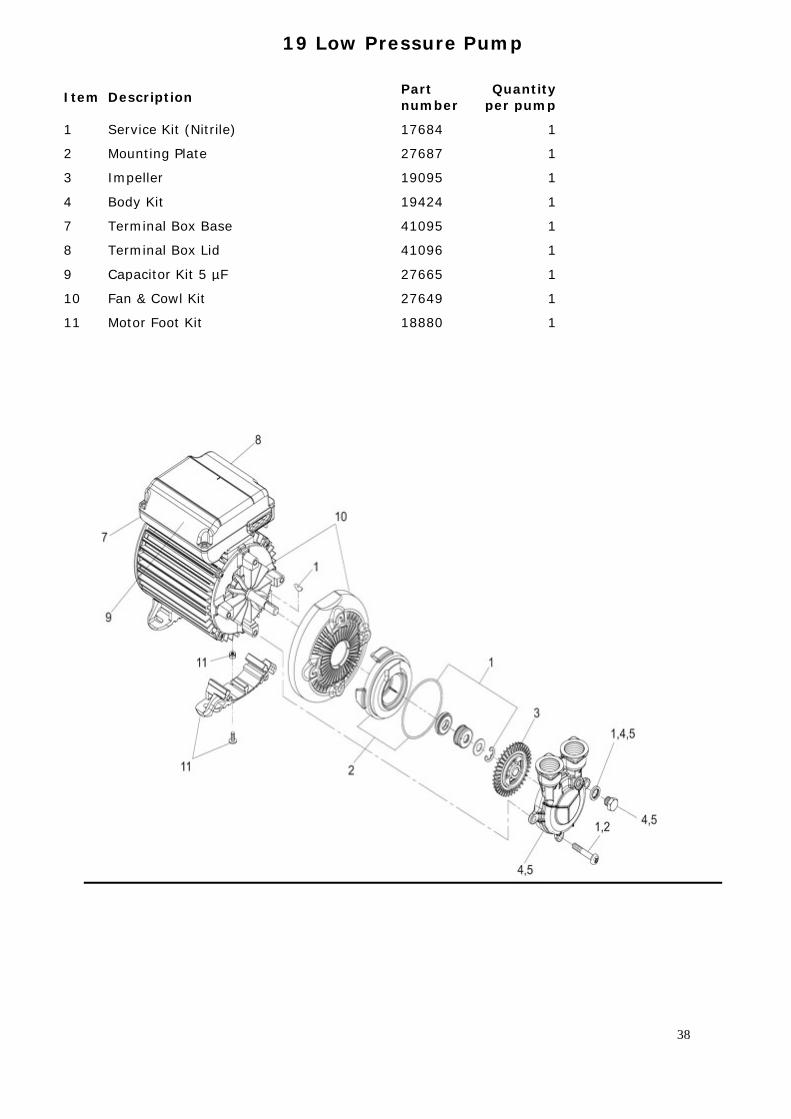
19 Low Pressure Pump
Item Description Part number
Quantity per pump
1 Service Kit (Nitrile) 17684 1 2 Mounting Plate 27687 1 3 Impeller 19095 1 4 Body Kit 19424 1 7 Terminal Box Base 41095 1 8 Terminal Box Lid 41096 1 9 Capacitor Kit 5 µF 27665 1 10 Fan & Cowl Kit 27649 1 11 Motor Foot Kit 18880 1
38
20. High Pressure Pump Maintenance
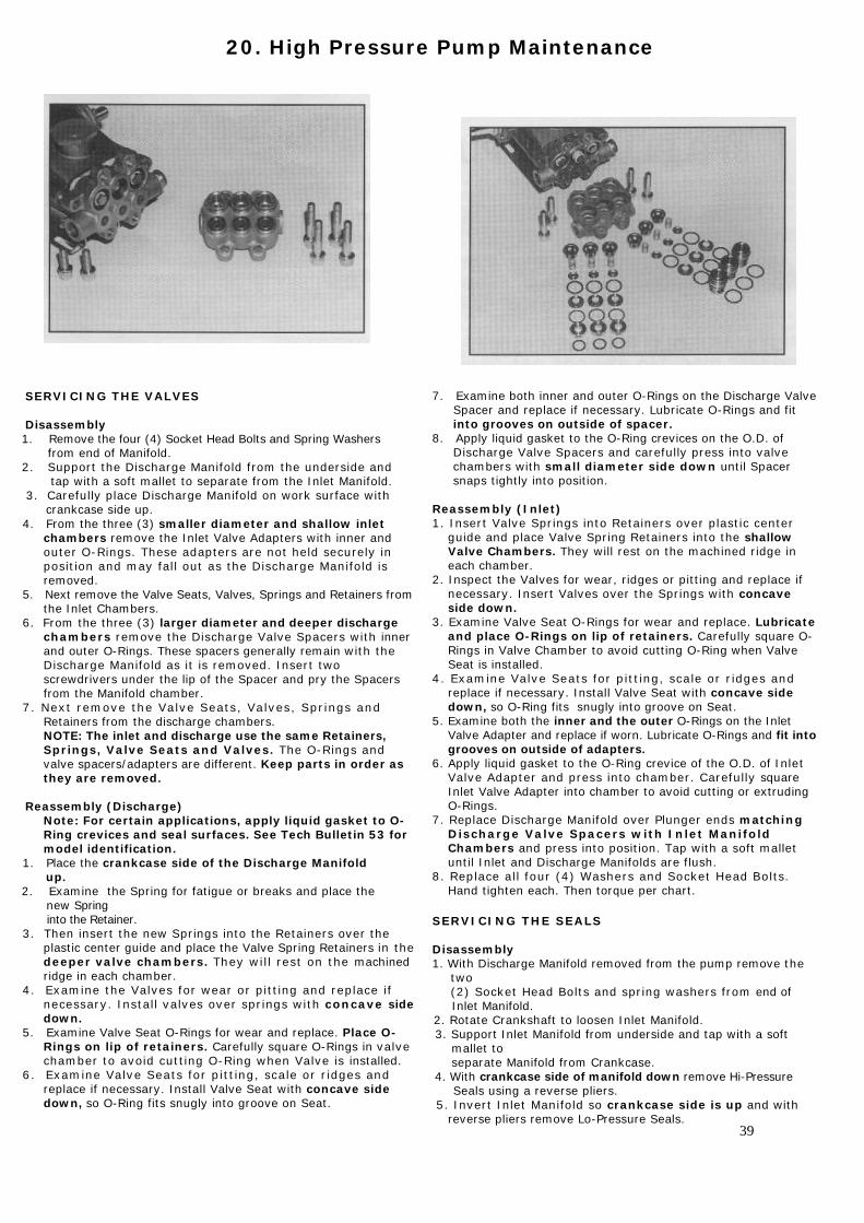
SERVICING THE VALVES Disassembly 1. Remove the four (4) Socket Head Bolts and Spring Washers from end of Manifold.
2. Support the Discharge Manifold from the underside and tap with a soft mallet to separate from the Inlet Manifold. 3. Carefully place Discharge Manifold on work surface with
crankcase side up. 4. From the three (3) smaller diameter and shallow inlet
chambers remove the Inlet Valve Adapters with inner and outer O-Rings. These adapters are not held securely in position and may fall out as the Discharge Manifold is removed.
5. Next remove the Valve Seats, Valves, Springs and Retainers from the Inlet Chambers.
6. From the three (3) larger diameter and deeper discharge chambers remove the Discharge Valve Spacers with inner and outer O-Rings. These spacers generally remain with the Discharge Manifold as it is removed. Insert two screwdrivers under the lip of the Spacer and pry the Spacers from the Manifold chamber.
7. Next remove the Valve Seats, Valves, Springs and Retainers from the discharge chambers. NOTE: The inlet and discharge use the same Retainers, Springs, Valve Seats and Valves. The O-Rings and valve spacers/adapters are different. Keep parts in order as they are removed.
Reassembly (Discharge)
Note: For certain applications, apply liquid gasket to O-Ring crevices and seal surfaces. See Tech Bulletin 53 for model identification.
1. Place the crankcase side of the Discharge Manifold up. 2. Examine the Spring for fatigue or breaks and place the new Spring into the Retainer. 3. Then insert the new Springs into the Retainers over the
plastic center guide and place the Valve Spring Retainers in the deeper valve chambers. They will rest on the machined ridge in each chamber.
4. Examine the Valves for wear or pitting and replace if necessary. Install valves over springs with concave side down.
5. Examine Valve Seat O-Rings for wear and replace. Place O-Rings on lip of retainers. Carefully square O-Rings in valve chamber to avoid cutting O-Ring when Valve is installed.
6. Examine Valve Seats for pitting, scale or ridges and replace if necessary. Install Valve Seat with concave side down, so O-Ring fits snugly into groove on Seat.
7. Examine both inner and outer O-Rings on the Discharge Valve Spacer and replace if necessary. Lubricate O-Rings and fit into grooves on outside of spacer.
8. Apply liquid gasket to the O-Ring crevices on the O.D. of Discharge Valve Spacers and carefully press into valve chambers with small diameter side down until Spacer snaps tightly into position.
Reassembly (Inlet) 1. Insert Valve Springs into Retainers over plastic center
guide and place Valve Spring Retainers into the shallow Valve Chambers. They will rest on the machined ridge in each chamber.
2. Inspect the Valves for wear, ridges or pitting and replace if necessary. Insert Valves over the Springs with concave side down.
3. Examine Valve Seat O-Rings for wear and replace. Lubricate and place O-Rings on lip of retainers. Carefully square O-Rings in Valve Chamber to avoid cutting O-Ring when Valve Seat is installed.
4. Examine Valve Seats for pitting, scale or ridges and replace if necessary. Install Valve Seat with concave side down, so O-Ring fits snugly into groove on Seat.
5. Examine both the inner and the outer O-Rings on the Inlet Valve Adapter and replace if worn. Lubricate O-Rings and fit into grooves on outside of adapters.
6. Apply liquid gasket to the O-Ring crevice of the O.D. of Inlet Valve Adapter and press into chamber. Carefully square Inlet Valve Adapter into chamber to avoid cutting or extruding O-Rings.
7. Replace Discharge Manifold over Plunger ends matching Discharge Valve Spacers with Inlet Manifold Chambers and press into position. Tap with a soft mallet until Inlet and Discharge Manifolds are flush.
8. Replace all four (4) Washers and Socket Head Bolts. Hand tighten each. Then torque per chart.
SERVICING THE SEALS
Disassembly 1. With Discharge Manifold removed from the pump remove the two (2) Socket Head Bolts and spring washers from end of Inlet Manifold. 2. Rotate Crankshaft to loosen Inlet Manifold. 3. Support Inlet Manifold from underside and tap with a soft mallet to separate Manifold from Crankcase. 4. With crankcase side of manifold down remove Hi-Pressure Seals using a reverse pliers. 5. Invert Inlet Manifold so crankcase side is up and with
reverse pliers remove Lo-Pressure Seals.
39
Reassembly
Note: For certain applications, apply liquid gasket to O-Ring crevices and seal surfaces. See Tech Bulletin 53 for model identification.
1. Examine Lo-Pressure Seal for wear or spring failure and replace if necessary. With crankcase side of inlet manifold up, press the new Lo-Pressure Seal into the Valve Chamber with Garter Spring down. Carefully square seal into position.
2. Examine Hi-Pressure Seal for wear and replace if necessary. Invert Inlet Manifold with crankcase side down and press the new seal into the Manifold chamber with v-side up (metal side down) until completely seated.
3. Rotate the Shaft so the two (2) outside Plungers are extended and lined-up.
4. Examine O-Rings on both the Discharge Spacer and Inlet
Valve Adapter for cuts or wear and replace as needed. 5. Lubricate Plungers and carefully slide the Inlet
Manifold over the Plungers and press into the Crankcase. 6. Replace two (2) M10 Inlet Manifold Socket Head Bolts, and Washers, hand tighten and then torque per chart. 7. Then carefully slip the Discharge Manifold onto Plungers
and press the exposed Discharge Valve Spacers into the Inlet Manifold. Tap with a soft mallet until flush.
8. Replace the four (4) M10 Discharge Manifold Socket Head Bolts and Washers and hand tighten. Then torque per chart.
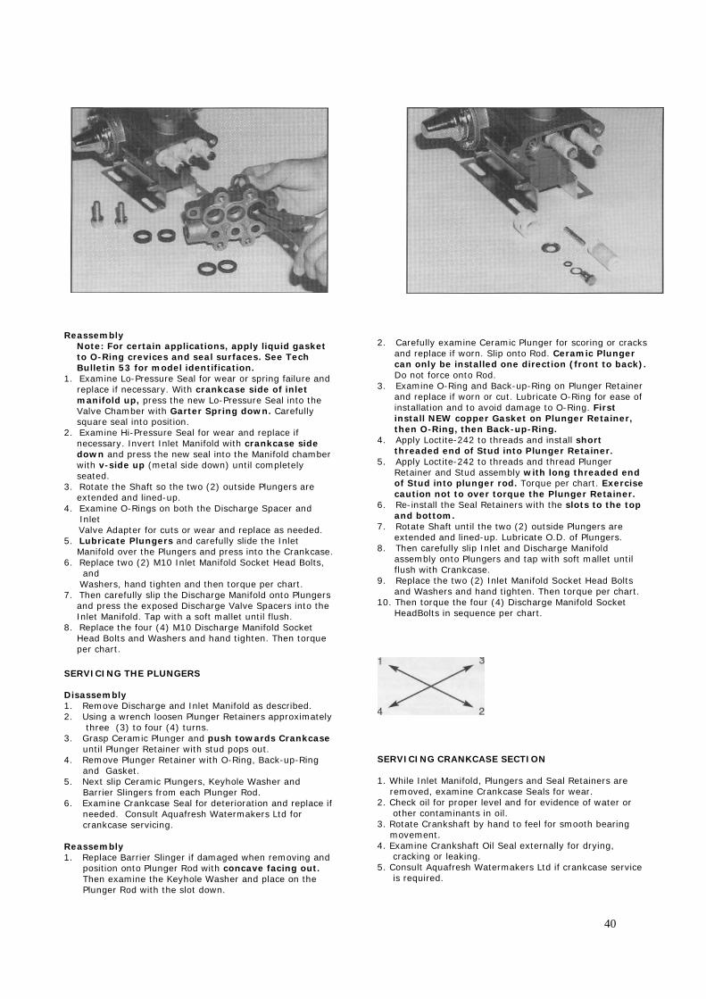
SERVICING THE PLUNGERS Disassembly 1. Remove Discharge and Inlet Manifold as described. 2. Using a wrench loosen Plunger Retainers approximately three (3) to four (4) turns. 3. Grasp Ceramic Plunger and push towards Crankcase until Plunger Retainer with stud pops out. 4. Remove Plunger Retainer with O-Ring, Back-up-Ring and Gasket. 5. Next slip Ceramic Plungers, Keyhole Washer and Barrier Slingers from each Plunger Rod. 6. Examine Crankcase Seal for deterioration and replace if needed. Consult Aquafresh Watermakers Ltd for crankcase servicing. Reassembly 1. Replace Barrier Slinger if damaged when removing and position onto Plunger Rod with concave facing out. Then examine the Keyhole Washer and place on the Plunger Rod with the slot down.
2. Carefully examine Ceramic Plunger for scoring or cracks
and replace if worn. Slip onto Rod. Ceramic Plunger can only be installed one direction (front to back). Do not force onto Rod.
3. Examine O-Ring and Back-up-Ring on Plunger Retainer and replace if worn or cut. Lubricate O-Ring for ease of installation and to avoid damage to O-Ring. First install NEW copper Gasket on Plunger Retainer, then O-Ring, then Back-up-Ring.
4. Apply Loctite-242 to threads and install short threaded end of Stud into Plunger Retainer.
5. Apply Loctite-242 to threads and thread Plunger Retainer and Stud assembly with long threaded end of Stud into plunger rod. Torque per chart. Exercise caution not to over torque the Plunger Retainer.
6. Re-install the Seal Retainers with the slots to the top and bottom.
7. Rotate Shaft until the two (2) outside Plungers are extended and lined-up. Lubricate O.D. of Plungers.
8. Then carefully slip Inlet and Discharge Manifold assembly onto Plungers and tap with soft mallet until flush with Crankcase.
9. Replace the two (2) Inlet Manifold Socket Head Bolts and Washers and hand tighten. Then torque per chart.
10. Then torque the four (4) Discharge Manifold Socket HeadBolts in sequence per chart.
SERVICING CRANKCASE SECTION 1. While Inlet Manifold, Plungers and Seal Retainers are removed, examine Crankcase Seals for wear. 2. Check oil for proper level and for evidence of water or other contaminants in oil. 3. Rotate Crankshaft by hand to feel for smooth bearing movement. 4. Examine Crankshaft Oil Seal externally for drying, cracking or leaking. 5. Consult Aquafresh Watermakers Ltd if crankcase service is required.
40
21. Assembly and Maintenance Instructions for Plasticon Vessels
I - SETTING UP
II - JOINTING AND FIXING
III - PRESSURIZATION
IV - CONVEYED LIQUIDS
ANNEX 1 I - SETTING UP Pressure vessels are designed to be used with osmosis or filtration membrane with pressures mentioned for each reference. All membranes' models can be easily adapted on vessels with specific adaptors supplied with the vessel. All gaskets must be lubricated while setting up. For lubrication of o-ring seals and membranes use only a lubricating stuff recommended by the membranes manufacturer. The different parts must be set up without any special tool. Tie bars' nuts must be set up by hand and with glue (type "Loctite") to avoid any release by vibrations. Screwing of nuts must be made so that plates should be perfectly perpendicular to tie bars' axis. The holding couple must not exceed 0,5 mdaN for 2,5 " vessel diameter, 0,5 mdaN for 4" vessel diameter and 1 mdaN for 8" vessel diameter. II - JOINTING & FIXING Despite their high resistance pressure vessels in fibre and resin get out of shape with pressure you must therefore let distortion freedom : - fitting, - on supports (osmorack supports enable this distortion). Fitting on inlets and outputs (gas thread or NPT) must be realized by a screwing by hand followed by one fourth rotation with a chuck key. In case of leak do not try to reduce it by an additional screwing. You must not apply important vertical load to connections.
41
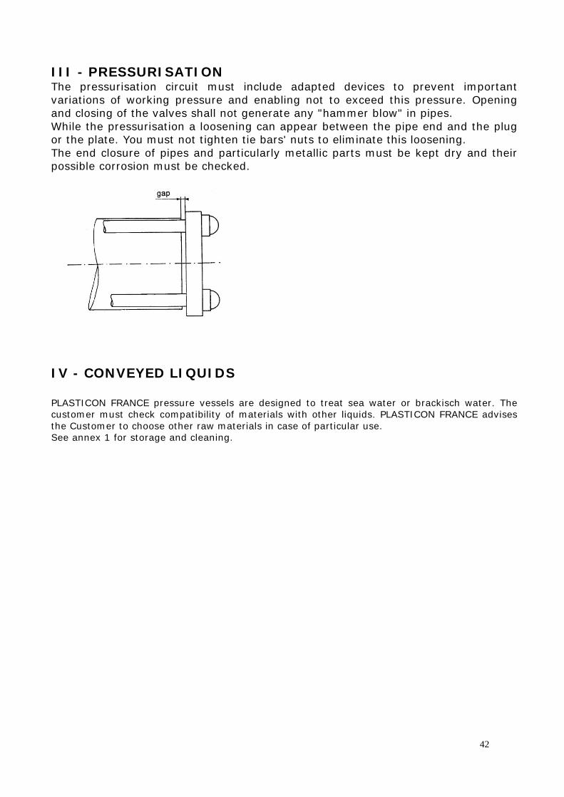
III - PRESSURISATION The pressurisation circuit must include adapted devices to prevent important variations of working pressure and enabling not to exceed this pressure. Opening and closing of the valves shall not generate any "hammer blow" in pipes. While the pressurisation a loosening can appear between the pipe end and the plug or the plate. You must not tighten tie bars' nuts to eliminate this loosening. The end closure of pipes and particularly metallic parts must be kept dry and their possible corrosion must be checked.
IV - CONVEYED LIQUIDS PLASTICON FRANCE pressure vessels are designed to treat sea water or brackisch water. The customer must check compatibility of materials with other liquids. PLASTICON FRANCE advises the Customer to choose other raw materials in case of particular use. See annex 1 for storage and cleaning.
42
ANNEX 1 Chemical cleaning and storage solutions recommended for the pressure vessels. 5-1 : Cleaning Main membranes manufacturers recommend the cleaning solutions hereafter. They are as well recommended for the pressure vessels. Solution nbr 1 : 0,1% NaOH + 0,1% Na EDTA Solution nbr 2 : 0,1% NaOH + 0,05% Na-DDS Solution nbr 3 : 1,0% STP + 1,0% TSP + 1% Na EDTA Solution nbr 4 : 0,2% Hcl Solution nbr 5 : 0,5% H3 PO4 Solution nbr 6 : 2,0% NH2 SO3H Solution nbr 7 : 1,0% NaS2O4 The percentages are understood in weight value. Working temperature being less than or equal to 30°C. Using of a cleaning solution from retail trade is subjected to an agreement from PLASTICON FRANCE beforehand. In order to be able to consider special requests, it will be advisable to send the chemical structure of the product or a one litre - sample for testing. For the pressure vessels we warn against use of a cleaning solution with 70% methanol indicated by some membranes manufacturers for the disinfection. Generally the customer shall check that the recommendations given by membranes manufacturers meet our recommendations. All the cleaning solutions with recommendations that would not meet ours shall be avoided, or we should be consulted before every application. 5-2 : Preservation and storage The use of Formaldehyde concentrated from 0,5 to 1% is possible until a maximum temperature of 30°C. In the case of a use of sodium bisulphite, the solution will consist of NaHSO3 from 1 to -1,5%, neutralized (pH 6 to 7) and buffered with 500 ppm NaHCO3 solution. The inside of the pressure vessel shall be free of air in order to avoid an oxidation process of the sodium bisulphite, moreover the pH will be checked once per week and shall never be inferior to 3. The solution will be renewed at least each month.
I - PREPARING PLUGS
II - FITTING MEMBRANES
III - FITTING HEADS
IV - FITTING TIE-RODS
V - CONNECTING PIPEWORK
VI - SAFETY PRECAUTIONS
43
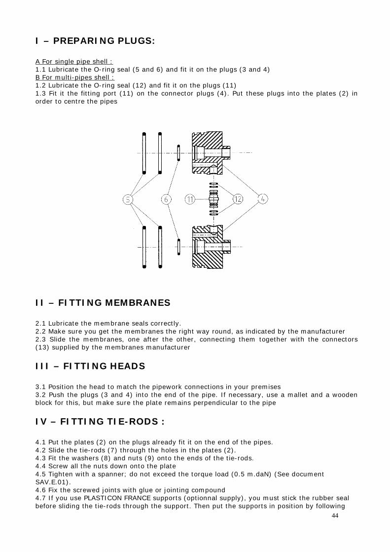
I – PREPARING PLUGS: A For single pipe shell : 1.1 Lubricate the O-ring seal (5 and 6) and fit it on the plugs (3 and 4) B For multi-pipes shell : 1.2 Lubricate the O-ring seal (12) and fit it on the plugs (11) 1.3 Fit it the fitting port (11) on the connector plugs (4). Put these plugs into the plates (2) in order to centre the pipes
II – FITTING MEMBRANES 2.1 Lubricate the membrane seals correctly. 2.2 Make sure you get the membranes the right way round, as indicated by the manufacturer 2.3 Slide the membranes, one after the other, connecting them together with the connectors (13) supplied by the membranes manufacturer III – FITTING HEADS 3.1 Position the head to match the pipework connections in your premises 3.2 Push the plugs (3 and 4) into the end of the pipe. If necessary, use a mallet and a wooden block for this, but make sure the plate remains perpendicular to the pipe IV – FITTING TIE-RODS : 4.1 Put the plates (2) on the plugs already fit it on the end of the pipes. 4.2 Slide the tie-rods (7) through the holes in the plates (2). 4.3 Fit the washers (8) and nuts (9) onto the ends of the tie-rods. 4.4 Screw all the nuts down onto the plate 4.5 Tighten with a spanner; do not exceed the torque load (0.5 m.daN) (See document SAV.E.01). 4.6 Fix the screwed joints with glue or jointing compound 4.7 If you use PLASTICON FRANCE supports (optionnal supply), you must stick the rubber seal before sliding the tie-rods through the support. Then put the supports in position by following
44
the measurements A and B given in the technical document for the type of pressure vessel you have ordered. Fix the upper with the lower supports. Fit it the connecting piece between supports if you order a multi-pipes shell. V – CONNECTING PIPEWORK 5.1 Connect to the pipework, taking care to do this in such a way that no vertical strain is placed on the ports, and that the body is free to expand under pressure (see document SAV.E.01) VI – SAFETY PRECAUTIONS 6.1 Before placing under pressure, check that the tie-rods are tightened; raise the pressure gradually. 6.2 Do not make adjustements to any equipment under pressure. 6.3 Follow the procedures for installation and use (document SAV.E.01)
Failure to follow these precautions may put lives at risk.
45
22. WARRANTY AQUAFRESH WATERMAKERS warrants to the original purchaser only that the Aquafresh system will be free from defects in material and workmanship under the conditions of normal use and service for a period of twelve months from the date of installation or fourteen months from date of dispatch of the goods from the factory, whichever is the earlier. Liability under this warranty shall be limited to repair or replacement of the defective system or component, at the option of Aquafresh Watermakers and under no circumstances shall Aquafresh Watermakers be liable for consequential, incidental or other damages arising out of or in any way connected, with the failure of the system to perform as set out herein. In the unlikely event of a defect, malfunction or failure of the system during the warranty period, Aquafresh Watermakers will repair or replace at its option without charge to the customer the system or component which upon examination by Aquafresh Watermakers shall appear to be defective or not up to specification. To obtain this service the defective component must be returned to Aquafresh Watermakers together with proven date of purchase or delivery. Aquafresh Watermakers shall not be liable for any transportation or travel expenses. This warranty does not extend to any system or component part which has been subject to misuse, neglect, accident, improper installation or subject to use in violation of the maintenance or operating instructions furnished by Aquafresh Watermakers nor does it extend to products on which serial numbers have been removed or defaced. This warranty does not extend to the reverse osmosis membranes due to the possibility of unintentional damage by the user. Instead of warranty Aquafresh Watermakers offer the customer an exchange service whereby Aquafresh Watermakers will at any time during the system life replace any defective membrane or clean any fouled membrane for a charge equal to 75% of the then current list price for the membrane. The subject membrane shall be returned to Aquafresh Watermakers with full payment enclosed, including transportation costs, and Aquafresh Watermakers shall expedite the appropriate service. This warranty extends to the original purchaser only and is in lieu of all other express or implied warranties including those of merchantability and fitness for a particular purpose. Original Purchaser: Name: Address: Installed On: Vessels Name and Type: Purchased From: Name: Address: Installation date: Model No: Serial No:
46
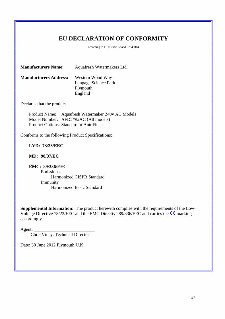
EU DECLARATION OF CONFORMITY
according to ISO Guide 22 and EN 45014
Manufacturers Name: Aquafresh Watermakers Ltd. Manufacturers Address: Western Wood Way Langage Science Park Plymouth England Declares that the product Product Name: Aquafresh Watermaker 240v AC Models Model Number: AFD####AC (All models) Product Options: Standard or AutoFlush Conforms to the following Product Specifications: LVD: 73/23/EEC MD: 98/37/EC EMC: 89/336/EEC Emissions Harmonized CISPR Standard Immunity Harmonized Basic Standard Supplemental Information: The product herewith complies with the requirements of the Low-Voltage Directive 73/23/EEC and the EMC Directive 89/336/EEC and carries the marking accordingly. Agent: ___________________________ Chris Viney, Technical Director Date: 30 June 2012 Plymouth U.K
47