Embed Size (px)
Citation preview
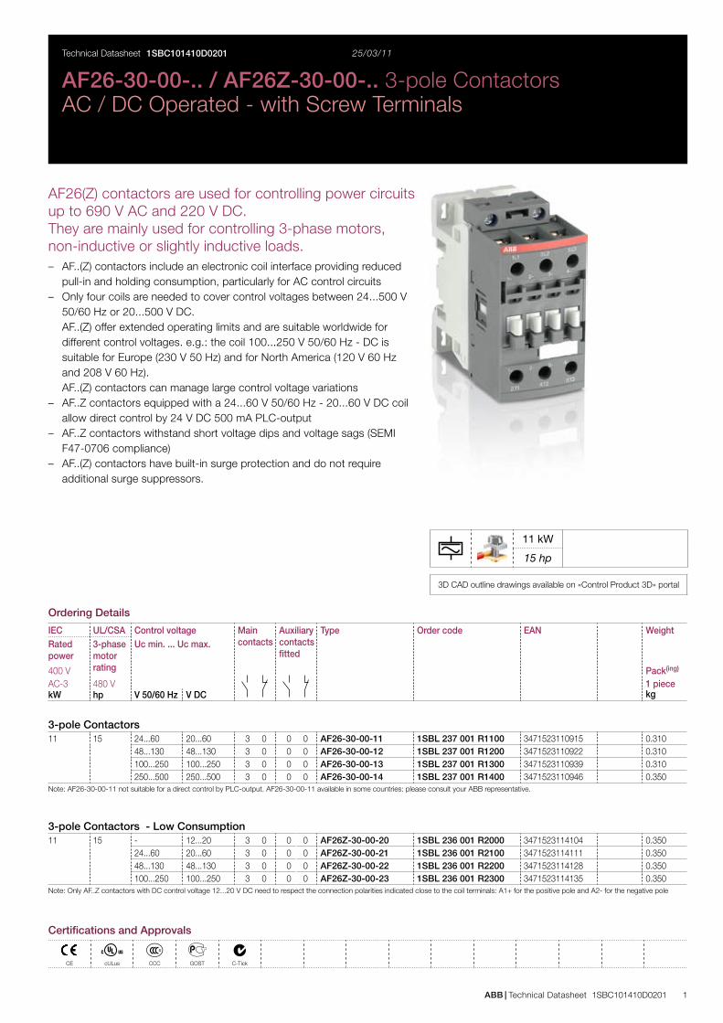
ABB | Technical Datasheet 1SBC101410D0201 1
3D CAD outline drawings available on «Control Product 3D» portal
11 kW
15 hp
Technical Datasheet 25/03/11
AF26-30-00-.. / AF26Z-30-00-.. 3-pole ContactorsAC / DC Operated - with Screw Terminals
Ordering Details
IEC UL/CSA Control voltage Main contacts
Auxiliary contacts fitted
Type Order code EAN WeightRated power
3-phase motor rating
Uc min. ... Uc max.
400 V Pack(ing)
AC-3 480 V 1 piecekW hp V 50/60 Hz V DC kg
3-pole Contactors11 15 24...60 20...60 3 0 0 0 AF26-30-00-11 1SBL 237 001 R1100 3471523110915 0.310
48...130 48...130 3 0 0 0 AF26-30-00-12 1SBL 237 001 R1200 3471523110922 0.310100...250 100...250 3 0 0 0 AF26-30-00-13 1SBL 237 001 R1300 3471523110939 0.310250...500 250...500 3 0 0 0 AF26-30-00-14 1SBL 237 001 R1400 3471523110946 0.350
Note: AF26-30-00-11 not suitable for a direct control by PLC-output. AF26-30-00-11 available in some countries: please consult your ABB representative.
3-pole Contactors - Low Consumption11 15 - 12...20 3 0 0 0 AF26Z-30-00-20 1SBL 236 001 R2000 3471523114104 0.350
24...60 20...60 3 0 0 0 AF26Z-30-00-21 1SBL 236 001 R2100 3471523114111 0.35048...130 48...130 3 0 0 0 AF26Z-30-00-22 1SBL 236 001 R2200 3471523114128 0.350100...250 100...250 3 0 0 0 AF26Z-30-00-23 1SBL 236 001 R2300 3471523114135 0.350
Note: Only AF..Z contactors with DC control voltage 12...20 V DC need to respect the connection polarities indicated close to the coil terminals: A1+ for the positive pole and A2- for the negative pole
AF26(Z) contactors are used for controlling power circuits up to 690 V AC and 220 V DC.They are mainly used for controlling 3-phase motors, non-inductive or slightly inductive loads.
AF..(Z) contactors include an electronic coil interface providing reduced –pull-in and holding consumption, particularly for AC control circuitsOnly four coils are needed to cover control voltages between 24...500 V –50/60 Hz or 20...500 V DC.AF..(Z) offer extended operating limits and are suitable worldwide for different control voltages. e.g.: the coil 100...250 V 50/60 Hz - DC is suitable for Europe (230 V 50 Hz) and for North America (120 V 60 Hz and 208 V 60 Hz). AF..(Z) contactors can manage large control voltage variationsAF..Z contactors equipped with a 24...60 V 50/60 Hz - 20...60 V DC coil –allow direct control by 24 V DC 500 mA PLC-outputAF..Z contactors withstand short voltage dips and voltage sags (SEMI –F47-0706 compliance)AF..(Z) contactors have built-in surge protection and do not require –additional surge suppressors.
1SBC101410D0201
Certifications and Approvals
CE cULus CCC GOST C-Tick
2 Technical Datasheet 1SBC101410D0201 | ABB
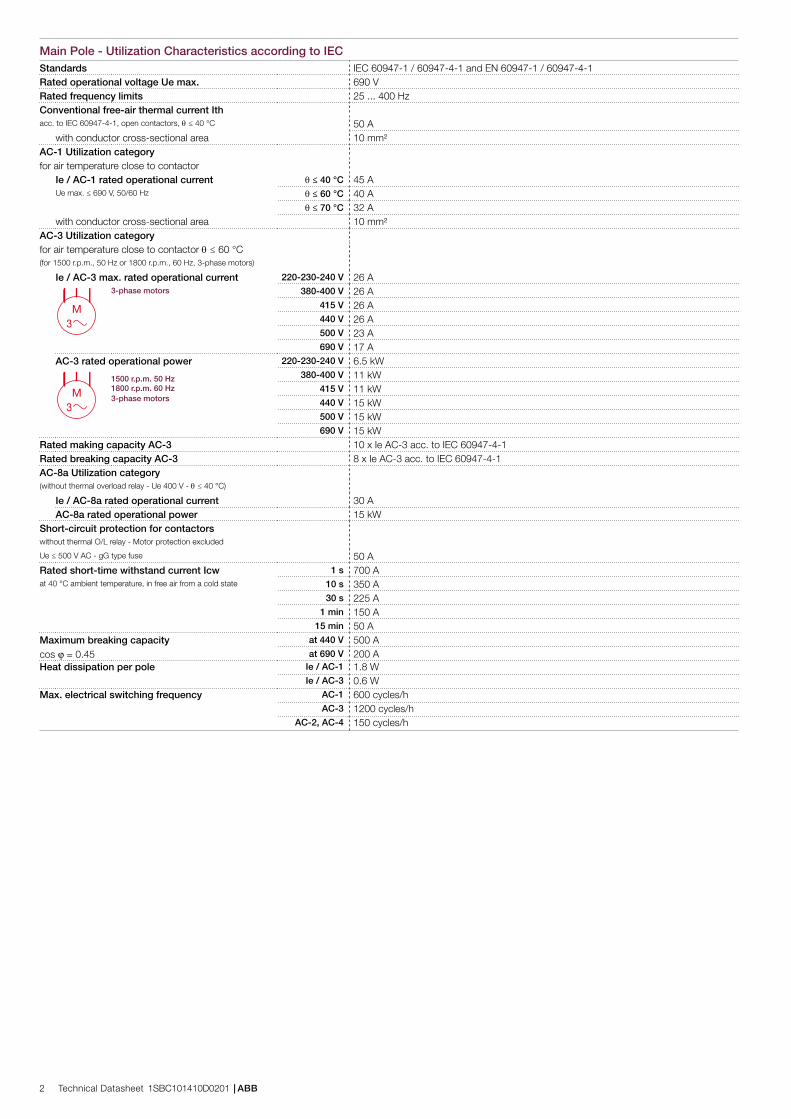
Main Pole - Utilization Characteristics according to IECStandards IEC 60947-1 / 60947-4-1 and EN 60947-1 / 60947-4-1Rated operational voltage Ue max. 690 VRated frequency limits 25 ... 400 HzConventional free-air thermal current Ithacc. to IEC 60947-4-1, open contactors, θ ≤ 40 °C 50 A
with conductor cross-sectional area 10 mm²AC-1 Utilization categoryfor air temperature close to contactor
Ie / AC-1 rated operational current θ ≤ 40 °C 45 AUe max. ≤ 690 V, 50/60 Hz θ ≤ 60 °C 40 A
θ ≤ 70 °C 32 Awith conductor cross-sectional area 10 mm²
AC-3 Utilization categoryfor air temperature close to contactor θ ≤ 60 °C(for 1500 r.p.m., 50 Hz or 1800 r.p.m., 60 Hz, 3-phase motors)
Ie / AC-3 max. rated operational current 220-230-240 V 26 A
M3
3-phase motors 380-400 V 26 A415 V 26 A440 V 26 A500 V 23 A690 V 17 A
AC-3 rated operational power 220-230-240 V 6.5 kW
M3
1500 r.p.m. 50 Hz 380-400 V 11 kW1800 r.p.m. 60 Hz 415 V 11 kW3-phase motors 440 V 15 kW
500 V 15 kW690 V 15 kW
Rated making capacity AC-3 10 x Ie AC-3 acc. to IEC 60947-4-1Rated breaking capacity AC-3 8 x Ie AC-3 acc. to IEC 60947-4-1AC-8a Utilization category(without thermal overload relay - Ue 400 V - θ ≤ 40 °C)
Ie / AC-8a rated operational current 30 AAC-8a rated operational power 15 kW
Short-circuit protection for contactorswithout thermal O/L relay - Motor protection excluded
Ue ≤ 500 V AC - gG type fuse 50 ARated short-time withstand current Icw 1 s 700 Aat 40 °C ambient temperature, in free air from a cold state 10 s 350 A
30 s 225 A1 min 150 A
15 min 50 AMaximum breaking capacity at 440 V 500 Acos φ = 0.45 at 690 V 200 AHeat dissipation per pole Ie / AC-1 1.8 W
Ie / AC-3 0.6 WMax. electrical switching frequency AC-1 600 cycles/h
AC-3 1200 cycles/hAC-2, AC-4 150 cycles/h
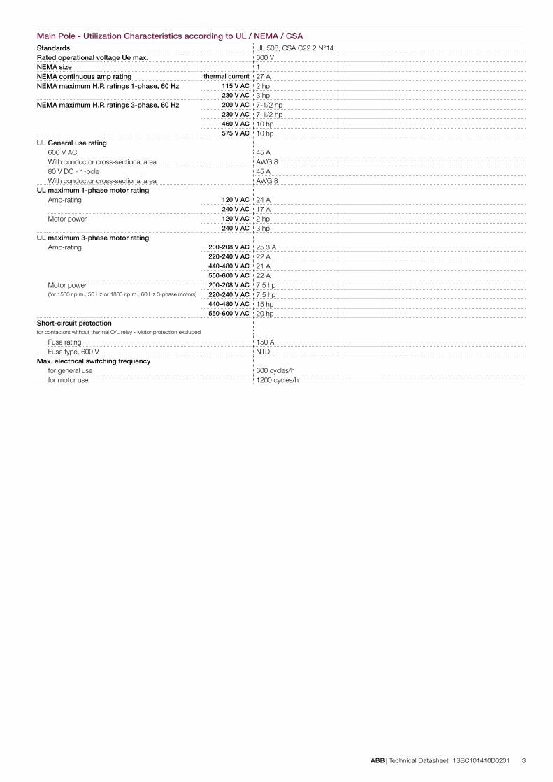
ABB | Technical Datasheet 1SBC101410D0201 3
Main Pole - Utilization Characteristics according to UL / NEMA / CSAStandards UL 508, CSA C22.2 N°14Rated operational voltage Ue max. 600 VNEMA size 1NEMA continuous amp rating thermal current 27 ANEMA maximum H.P. ratings 1-phase, 60 Hz 115 V AC 2 hp
230 V AC 3 hpNEMA maximum H.P. ratings 3-phase, 60 Hz 200 V AC 7-1/2 hp
230 V AC 7-1/2 hp460 V AC 10 hp575 V AC 10 hp
UL General use rating600 V AC 45 AWith conductor cross-sectional area AWG 880 V DC - 1-pole 45 AWith conductor cross-sectional area AWG 8
UL maximum 1-phase motor ratingAmp-rating 120 V AC 24 A
240 V AC 17 AMotor power 120 V AC 2 hp
240 V AC 3 hpUL maximum 3-phase motor rating
Amp-rating 200-208 V AC 25.3 A220-240 V AC 22 A440-480 V AC 21 A550-600 V AC 22 A
Motor power 200-208 V AC 7.5 hp(for 1500 r.p.m., 50 Hz or 1800 r.p.m., 60 Hz 3-phase motors) 220-240 V AC 7.5 hp
440-480 V AC 15 hp550-600 V AC 20 hp
Short-circuit protectionfor contactors without thermal O/L relay - Motor protection excluded
Fuse rating 150 AFuse type, 600 V NTD
Max. electrical switching frequencyfor general use 600 cycles/hfor motor use 1200 cycles/h
4 Technical Datasheet 1SBC101410D0201 | ABB
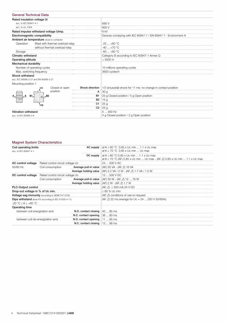
General Technical DataRated insulation voltage Ui
acc. to IEC 60947-4-1 690 Vacc. to UL /CSA 600 V
Rated impulse withstand voltage Uimp. 6 kVElectromagnetic compatibility Devices complying with IEC 60947-1 / EN 60947-1 - Environment AAmbient air temperature close to contactor
Operation fitted with thermal overload relay -25 ... +60 °Cwithout thermal overload relay -40 ... +70 °C
Storage -60 ... +80 °CClimatic withstand Category B according to IEC 60947-1 Annex QOperating altitude ≤ 3000 mMechanical durability
Number of operating cycles 10 millions operating cycles Max. switching frequency 3600 cycles/h
Shock withstandacc. IEC 60068-2-27 and EN 60068-2-27
Mounting position 1
B2A A B1
C2
C1 Closed or open position
Shock direction 1/2 sinusoidal shock for 11 ms: no change in contact positionA 30 g
B1 25 g Closed position / 5 g Open positionB2 15 gC1 25 gC2 25 g
Vibration withstand 5 ... 300 Hz4 g Closed position / 2 g Open positionacc. to IEC 60068-2-6
Magnet System CharacteristicsCoil operating limits AC supply at θ ≤ 60 °C 0.85 x Uc min ... 1.1 x Uc max
at θ ≤ 70 °C 0.85 x Uc min ... Uc maxacc. to IEC 60947-4-1
DC supply at θ ≤ 60 °C 0.85 x Uc min ... 1.1 x Uc maxat θ ≤ 70 °C (AF) 0.85 x Uc min ... Uc max - (AF..Z) 0.85 x Uc min ... 1.1 x Uc max
AC control voltage Rated control circuit voltage Uc 24 ... 500 V AC50/60 Hz Coil consumption Average pull-in value (AF) 50 VA - (AF..Z) 16 VA
Average holding value (AF) 2.2 VA / 2 W - (AF..Z) 1.7 VA / 1.5 WDC control voltage Rated control circuit voltage Uc 12 ... 500 V DC
Coil consumption Average pull-in value (AF) 50 W - (AF..Z) 12 ... 16 WAverage holding value (AF) 2 W - (AF..Z) 1.7 W
PLC-Output control (AF..Z) ≥ 500 mA 24 V DCDrop-out voltage in % of Uc min. ≤ 60 % Uc minVoltage sag immunity according to SEMI F47-0706 (AF..Z) conditions of use on requestDips withstand (level 0% according to IEC 61000-4-11) (AF..Z) 22 ms average for Uc = 24 ... 250 V 50/60Hz-20 °C ≤ θ ≤ +60 °COperating time
between coil energization and: N.O. contact closing 40 ... 95 msN.C. contact opening 38 ... 90 ms
between coil de-energization and: N.O. contact opening 11 ... 95 msN.C. contact closing 13 ... 98 ms
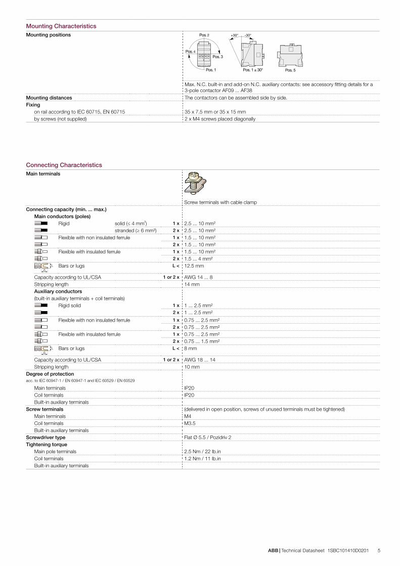
ABB | Technical Datasheet 1SBC101410D0201 5
Mounting CharacteristicsMounting positions
Pos. 5
Pos. 3
Pos. 2
Pos. 1 Pos. 1 ± 30°
+30° -30°
Pos. 4
Max. N.C. built-in and add-on N.C. auxiliary contacts: see accessory fitting details for a 3-pole contactor AF09 ... AF38
Mounting distances The contactors can be assembled side by side.Fixing
on rail according to IEC 60715, EN 60715 35 x 7.5 mm or 35 x 15 mmby screws (not supplied) 2 x M4 screws placed diagonally
Connecting CharacteristicsMain terminals
Screw terminals with cable clampConnecting capacity (min. ... max.)
Main conductors (poles)Rigid solid (≤ 4 mm²) 1 x 2.5 ... 10 mm²
stranded (≥ 6 mm²) 2 x 2.5 ... 10 mm²Flexible with non insulated ferrule 1 x 1.5 ... 10 mm²
2 x 1.5 ... 10 mm²Flexible with insulated ferrule 1 x 1.5 ... 10 mm²
2 x 1.5 ... 4 mm²L
6Bars or lugs L < 12.5 mm
Capacity according to UL/CSA 1 or 2 x AWG 14 ... 8Stripping length 14 mmAuxiliary conductors(built-in auxiliary terminals + coil terminals)
Rigid solid 1 x 1 ... 2.5 mm²2 x 1 ... 2.5 mm²
Flexible with non insulated ferrule 1 x 0.75 ... 2.5 mm²2 x 0.75 ... 2.5 mm²
Flexible with insulated ferrule 1 x 0.75 ... 2.5 mm²2 x 0.75 ... 1.5 mm²
L6
Bars or lugs L < 8 mm
Capacity according to UL/CSA 1 or 2 x AWG 18 ... 14Stripping length 10 mm
Degree of protection acc. to IEC 60947-1 / EN 60947-1 and IEC 60529 / EN 60529
Main terminals IP20Coil terminals IP20Built-in auxiliary terminals
Screw terminals (delivered in open position, screws of unused terminals must be tightened)Main terminals M4Coil terminals M3.5Built-in auxiliary terminals
Screwdriver type Flat Ø 5.5 / Pozidriv 2Tightening torque
Main pole terminals 2.5 Nm / 22 lb.inCoil terminals 1.2 Nm / 11 lb.inBuilt-in auxiliary terminals
6 Technical Datasheet 1SBC101410D0201 | ABB
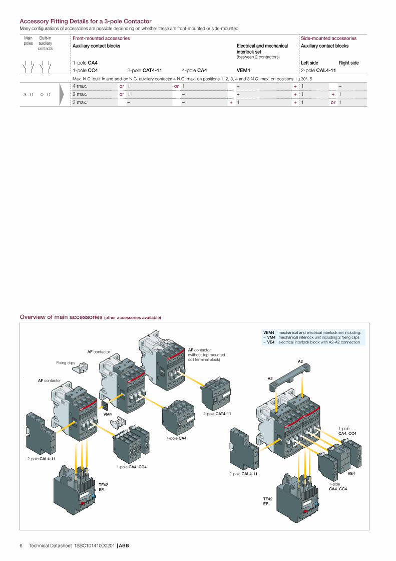
Accessory Fitting Details for a 3-pole ContactorMany configurations of accessories are possible depending on whether these are front-mounted or side-mounted.
Main poles
Built-in auxiliary contacts
Front-mounted accessories Side-mounted accessories
Auxiliary contact blocks Electrical and mechanical interlock set
Auxiliary contact blocks
(between 2 contactors)1-pole CA4 Left side Right side
1-pole CC4 2-pole CAT4-11 4-pole CA4 VEM4 2-pole CAL4-11
Max. N.C. built-in and add-on N.C. auxiliary contacts: 4 N.C. max. on positions 1, 2, 3, 4 and 3 N.C. max. on positions 1 ±30°, 5
4 max. or 1 or 1 – + 1 –
3 0 0 0 2 max. or 1 – – + 1 + 1
3 max. – – + 1 + 1 or 1
Overview of main accessories (other accessories available)
A2
VE4
AF contactor
4-pole CA4
2-pole CAT4-11
1-pole CA4, CC4
VM4
1-pole CA4, CC4
2-pole CAL4-11
2-pole CAL4-11
AF contactor(without top mounted coil terminal block)
TF42EF..
Fixing clips
TF42EF..
A2
AF contactor
1-pole CA4, CC4
VEM4 mechanical and electrical interlock set including:– VM4 mechanical interlock unit including 2 fixing clips– VE4 electrical interlock block with A2-A2 connection
Main poles
Built-in auxiliary contacts
Front-mounted accessories Side-mounted accessories
Auxiliary contact blocks Electrical and mechanical interlock set
Auxiliary contact blocks
(between 2 contactors)1-pole CA4 Left side Right side
1-pole CC4 2-pole CAT4-11 4-pole CA4 VEM4 2-pole CAL4-11
Max. N.C. built-in and add-on N.C. auxiliary contacts: 4 N.C. max. on positions 1, 2, 3, 4 and 3 N.C. max. on positions 1 ±30°, 5
4 max. or 1 or 1 – + 1 –
3 0 0 0 2 max. or 1 – – + 1 + 1
3 max. – – + 1 + 1 or 1
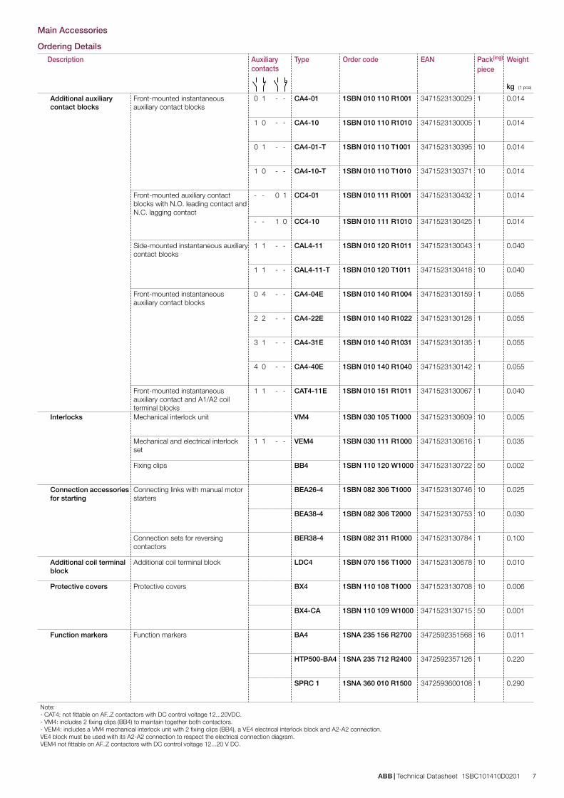
ABB | Technical Datasheet 1SBC101410D0201 7
Main Accessories
Ordering Details
Description Auxiliary contacts
Type Order code EAN Pack(ing) Weightpiece
kg (1 pce)
Additional auxiliary contact blocks
Front-mounted instantaneous auxiliary contact blocks
0 1 - - CA4-01 1SBN 010 110 R1001 3471523130029 1 0.014
1 0 - - CA4-10 1SBN 010 110 R1010 3471523130005 1 0.014
0 1 - - CA4-01-T 1SBN 010 110 T1001 3471523130395 10 0.014
1 0 - - CA4-10-T 1SBN 010 110 T1010 3471523130371 10 0.014
Front-mounted auxiliary contact blocks with N.O. leading contact and N.C. lagging contact
- - 0 1 CC4-01 1SBN 010 111 R1001 3471523130432 1 0.014
- - 1 0 CC4-10 1SBN 010 111 R1010 3471523130425 1 0.014
Side-mounted instantaneous auxiliary contact blocks
1 1 - - CAL4-11 1SBN 010 120 R1011 3471523130043 1 0.040
1 1 - - CAL4-11-T 1SBN 010 120 T1011 3471523130418 10 0.040
Front-mounted instantaneous auxiliary contact blocks
0 4 - - CA4-04E 1SBN 010 140 R1004 3471523130159 1 0.055
2 2 - - CA4-22E 1SBN 010 140 R1022 3471523130128 1 0.055
3 1 - - CA4-31E 1SBN 010 140 R1031 3471523130135 1 0.055
4 0 - - CA4-40E 1SBN 010 140 R1040 3471523130142 1 0.055
Front-mounted instantaneous auxiliary contact and A1/A2 coil terminal blocks
1 1 - - CAT4-11E 1SBN 010 151 R1011 3471523130067 1 0.040
Interlocks Mechanical interlock unit VM4 1SBN 030 105 T1000 3471523130609 10 0.005
Mechanical and electrical interlock set
1 1 - - VEM4 1SBN 030 111 R1000 3471523130616 1 0.035
Fixing clips BB4 1SBN 110 120 W1000 3471523130722 50 0.002
Connection accessories for starting
Connecting links with manual motor starters
BEA26-4 1SBN 082 306 T1000 3471523130746 10 0.025
BEA38-4 1SBN 082 306 T2000 3471523130753 10 0.030
Connection sets for reversing contactors
BER38-4 1SBN 082 311 R1000 3471523130784 1 0.100
Additional coil terminal block
Additional coil terminal block LDC4 1SBN 070 156 T1000 3471523130678 10 0.010
Protective covers Protective covers BX4 1SBN 110 108 T1000 3471523130708 10 0.006
BX4-CA 1SBN 110 109 W1000 3471523130715 50 0.001
Function markers Function markers BA4 1SNA 235 156 R2700 3472592351568 16 0.011
HTP500-BA4 1SNA 235 712 R2400 3472592357126 1 0.220
SPRC 1 1SNA 360 010 R1500 3472593600108 1 0.290
Note: - CAT4: not fittable on AF..Z contactors with DC control voltage 12...20VDC.- VM4: includes 2 fixing clips (BB4) to maintain together both contactors.- VEM4: includes a VM4 mechanical interlock unit with 2 fixing clips (BB4), a VE4 electrical interlock block and A2-A2 connection. VE4 block must be used with its A2-A2 connection to respect the electrical connection diagram. VEM4 not fittable on AF..Z contactors with DC control voltage 12...20 V DC.
45 1.77"
80 3
.15"
6 0
.24"
77 3.03"
71 2.80"
5.5 0.22"
35 m
m E
N/IE
C 60
715
10 0.39"
5.5 0.22"
35 1.38"
70 2
.76"
60 2
.36"
5 0
.20"
5 0.20"
ø 4.2 0.17"2 x
M4 8-32 UNC
35 1.38"
70 2
.76"
60 2
.36"
5 0
.20"
5 0.20"
ø 4.2 0.17"2 x
M4 8-32 UNC
45 1.77"
80 3
.15"
6 0
.24"
86 3.39"
80 3.15"
10 0.39"
35 m
m E
N/IE
C 60
715
5.5 0.22"
5.5 0.22"
45 1.77"
80 3
.15"
6 0
.24"
119.5 4.70"
80 3.15" 10 0.39"
35 m
m E
N/IE
C 60
715
5.5 0.22"
5.5 0.22"
43 1
.69"
80 3
.15"
6 0
.24"
12 0.47" 45 1.77"
86 3.39"
80 3.15"
10 0.39"
35 m
m E
N/IE
C 60
715
5.5 0.22"
5.5 0.22"
45 1.77"
80 3
.15"
6 0
.24"
119.5 4.70"
80 3.15" 10 0.39"
35 m
m E
N/IE
C 60
715
5.5 0.22"
5.5 0.22"
43 1
.69"
111.5 4.39"
80 3.15" 10 0.39"
35 m
m E
N/IE
C 60
715
5.5 0.22"
5.5 0.22"
43 1
.69"
45 1.77"
80 3
.15"
60 2
.36"
ø 4.2 0.17"
80 3.15"
70 2
.76"
5 0
.20"
5 0.20"
2 xM4 8-32 UNC
90 3.54"
91.5
3.6
0"
111.5 4.39"
80 3.15" 10 0.39"
35 m
m E
N/IE
C 60
715
5.5 0.22"
5.5 0.22"
43 1
.69"
60 2
.36"
ø 4.2 0.17"
80 3.15"
70 2
.76"
5 0
.20"
5 0.20"
2 xM4 8-32 UNC
90 3.54"
91.5
3.6
0"
111.5 4.39"
80 3.15" 10 0.39"
35 m
m E
N/IE
C 60
715
5.5 0.22"
5.5 0.22"
43 1
.69"
8 Technical Datasheet 1SBC101410D0201 | ABB
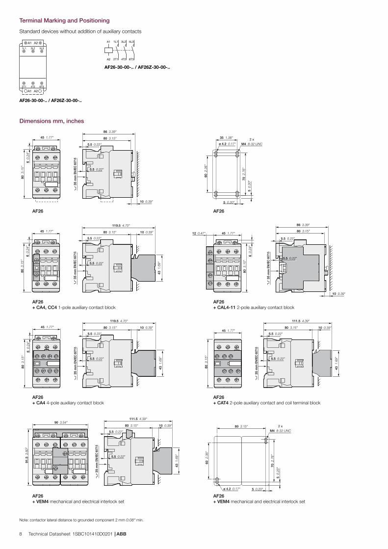
Terminal Marking and Positioning
Standard devices without addition of auxiliary contacts
5L3
6T3
3L2
4T2
1L1
2T1
A1 A2
A1 A2 5L33L2A1
A2 6T34T2
1L1
2T1
AF26-30-00-.. / AF26Z-30-00-..
AF26-30-00-.. / AF26Z-30-00-..
Dimensions mm, inches
AF26 AF26
AF26 AF26+ CA4, CC4 1-pole auxiliary contact block + CAL4-11 2-pole auxiliary contact block
AF26 AF26+ CA4 4-pole auxiliary contact block + CAT4 2-pole auxiliary contact and coil terminal block
AF26 AF26+ VEM4 mechanical and electrical interlock set + VEM4 mechanical and electrical interlock set
Note: contactor lateral distance to grounded component 2 mm 0.08" min.
Tech
nica
l Dat
ashe
et1S
BC
1014
10D
0201
(25
/03
/11
)
Contact us
ABB France Low Voltage Products Division 10, rue Ampère Z.I. - B.P. 114 F-69685 Chassieu cedex / France
You can find the address of your local sales organisation on the ABB home pagehttp://www.abb.com/contacts -> Low Voltage products
www.abb.com/lowvoltage
NoteWe reserve the right to make technical changes or modify the contents of this document without prior notice. With regard to purchase orders, the agreed particulars shall prevail. ABB does not accept any responsibility whatsoever for potential errors or possible lack of information in this document.
We reserve all rights in this document and in the subject matter and illustrations contained therein. Any reproduction, disclosure to third parties or utilization of its contents – in whole or in parts – is forbidden without prior written consent of ABB.
Copyright© 2011 ABBAll rights reserved