Embed Size (px)
Citation preview
ENSC 895-g200: COMMUNICATION NETWORKS
Project Title: OPNET Simulation of IEEE 802.11(WiFi) and
IEEE 802.16(WiMAX) in a small area
Spring 2010
FINAL PROJECT
Azadeh Farzin
http://www.sfu.ca/~afarzin
2
ABSTRACT
In the past few years the Wireless Local Area Network (WLAN) has been the
most popular choice of communication amongst users. WLAN, which is based on
the IEEE 802.11 standard, also known as Wireless Fidelity (WiFi), offers mobility
and flexibility with a relatively low cost to users. In addition, wireless technology
is providing easier internet access to areas that are too difficult and expensive to
reach with traditional wired infrastructure. IEEE 802.16, also known as Worldwide
Interoperability for Microwave Access (WiMAX), is another standard with similar
general principles as WiFi with the main advantages being it covers a larger area
and has a higher data rate. Comparing WiFi and WiMAX under optimal
conditions, the fastest WiFi connection is 54 megabits/second (Mbit/s) while
WiMAX is about 75 Mbit/s. WiFi has a range of about 30 meters and WiMAX can
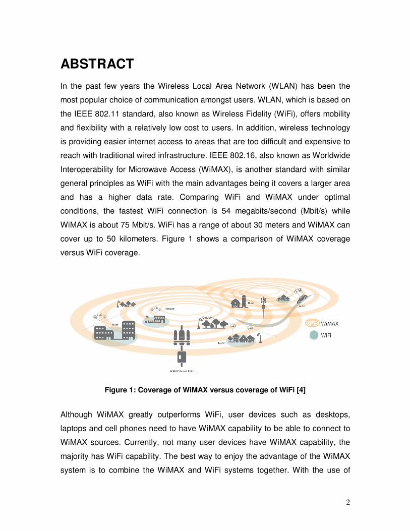
cover up to 50 kilometers. Figure 1 shows a comparison of WiMAX coverage
versus WiFi coverage.
Figure 1: Coverage of WiMAX versus coverage of WiFi [4]
Although WiMAX greatly outperforms WiFi, user devices such as desktops,
laptops and cell phones need to have WiMAX capability to be able to connect to
WiMAX sources. Currently, not many user devices have WiMAX capability, the
majority has WiFi capability. The best way to enjoy the advantage of the WiMAX
system is to combine the WiMAX and WiFi systems together. With the use of
3
WiMAX enabled WiFi routers in WLANs, WiMAX can be used in offices and
homes that are currently WiFi enabled. In this project the performance of using
WiMAX (802.16e) and WiFi (802.11g) in small offices is evaluated.
4
TABLE OF CONTENT
ABSTRACT ...................................................................................................................2
TABLE OF CONTENT .................................................................................................4
LIST OF TABLES .........................................................................................................5
LIST OF FIGURES .......................................................................................................6
LIST OF ACRONYMS ..................................................................................................7
1. INTRODUCTION...................................................................................................9
2. WiFi (IEEE 802.11g) BACKGROUND ..............................................................11
3. WiMAX (802.16e) BACKGROUND ...................................................................12
4. COMPARISON OF WiFi AND WiMAX .............................................................12
5. SIMULATION ......................................................................................................14
4.1) Simulation tool................................................................................................14
4.2) Models used ....................................................................................................14
4.3) Simulation Setup .............................................................................................15
4.4) General Description of Scenarios ....................................................................17
4.5) Parameter Setup ..............................................................................................17
4.6) Scenarios.........................................................................................................18
Scenario 1: WiMAX - Multipath Channel Model...................................................18
Scenario 2: WiMAX and WiFi range .....................................................................20
Scenario 3: WiMAX & WiFi performance with 2, 4 and 8 WLAN mobile nodes...21
6. SIMULATION RESULTS....................................................................................22
Scenario 1: Multipath Channel Model for WiMAX................................................22
Scenario 2: WiMAX and WiFi range .....................................................................24
Scenario 3: WiMAX & WiFi performance with 2, 4 and 8 WLAN mobile nodes...27
7. CONCLUSION ....................................................................................................30
8. FUTURE WORK .................................................................................................31
9. REFERENCES....................................................................................................31
10. ORIGINAL PROJECT IDEA............................................................................33
10.1 IEEE1588 ABSTRACT ...........................................................................33
10.2 IEEE1588 INTRODUCTION...................................................................33
10.3 IEEE1588 REFERENCES .......................................................................36
5
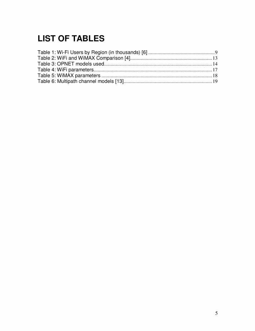
LIST OF TABLES
Table 1: Wi-Fi Users by Region (in thousands) [6] ...................................................9
Table 2: WiFi and WiMAX Comparison [4]...............................................................13
Table 3: OPNET models used...................................................................................14
Table 4: WiFi parameters...........................................................................................17
Table 5: WiMAX parameters .....................................................................................18
Table 6: Multipath channel models [13]....................................................................19
6
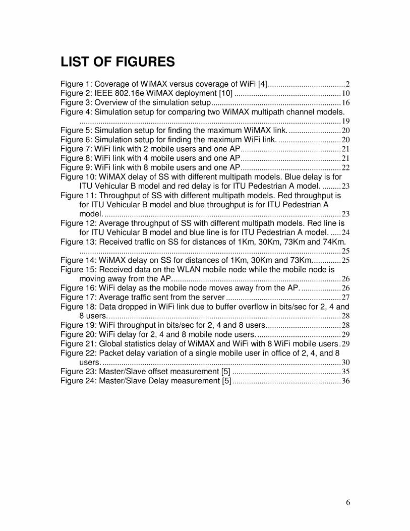
LIST OF FIGURES
Figure 1: Coverage of WiMAX versus coverage of WiFi [4] .....................................2
Figure 2: IEEE 802.16e WiMAX deployment [10] ...................................................10
Figure 3: Overview of the simulation setup..............................................................16
Figure 4: Simulation setup for comparing two WiMAX multipath channel models..............................................................................................................................19
Figure 5: Simulation setup for finding the maximum WiMAX link. .........................20
Figure 6: Simulation setup for finding the maximum WiFi link. ..............................20
Figure 7: WiFi link with 2 mobile users and one AP................................................21
Figure 8: WiFi link with 4 mobile users and one AP................................................21
Figure 9: WiFi link with 8 mobile users and one AP................................................22
Figure 10: WiMAX delay of SS with different multipath models. Blue delay is for ITU Vehicular B model and red delay is for ITU Pedestrian A model. .........23
Figure 11: Throughput of SS with different multipath models. Red throughput is for ITU Vehicular B model and blue throughput is for ITU Pedestrian A model. .................................................................................................................23
Figure 12: Average throughput of SS with different multipath models. Red line is for ITU Vehicular B model and blue line is for ITU Pedestrian A model. .....24
Figure 13: Received traffic on SS for distances of 1Km, 30Km, 73Km and 74Km..............................................................................................................................25
Figure 14: WiMAX delay on SS for distances of 1Km, 30Km and 73Km..............25
Figure 15: Received data on the WLAN mobile node while the mobile node is moving away from the AP.................................................................................26
Figure 16: WiFi delay as the mobile node moves away from the AP. ...................26
Figure 17: Average traffic sent from the server .......................................................27
Figure 18: Data dropped in WiFi link due to buffer overflow in bits/sec for 2, 4 and 8 users. ...............................................................................................................28
Figure 19: WiFi throughput in bits/sec for 2, 4 and 8 users....................................28
Figure 20: WiFi delay for 2, 4 and 8 mobile node users. ........................................29
Figure 21: Global statistics delay of WiMAX and WiFi with 8 WiFi mobile users .29
Figure 22: Packet delay variation of a single mobile user in office of 2, 4, and 8 users. ..................................................................................................................30
Figure 23: Master/Slave offset measurement [5] ....................................................35
Figure 24: Master/Slave Delay measurement [5] ....................................................36
7
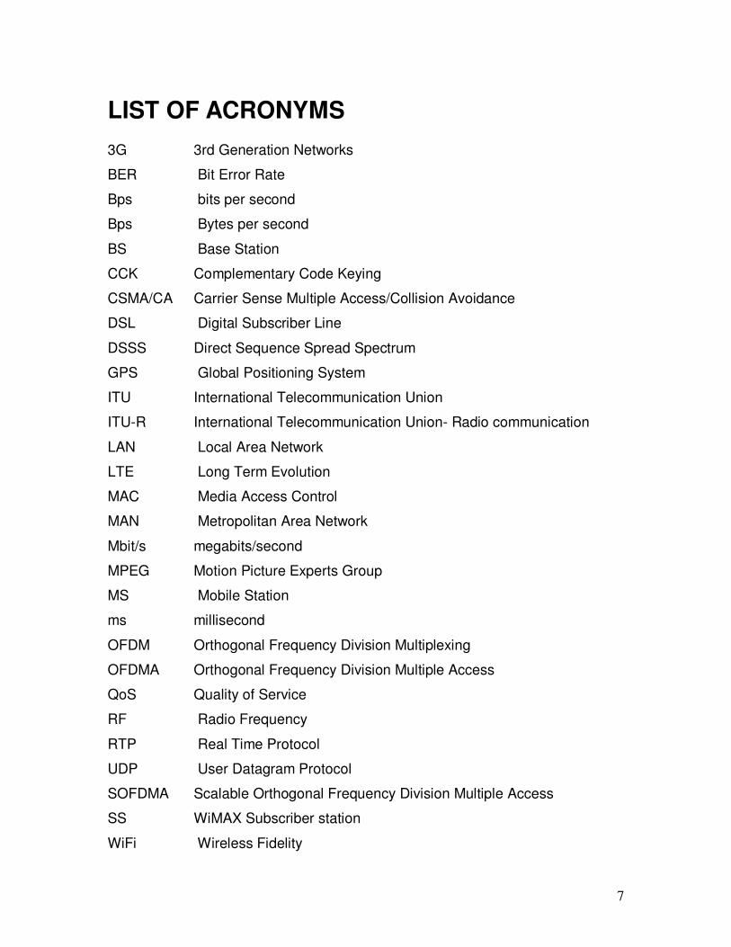
LIST OF ACRONYMS
3G 3rd Generation Networks
BER Bit Error Rate
Bps bits per second
Bps Bytes per second
BS Base Station
CCK Complementary Code Keying
CSMA/CA Carrier Sense Multiple Access/Collision Avoidance
DSL Digital Subscriber Line
DSSS Direct Sequence Spread Spectrum
GPS Global Positioning System
ITU International Telecommunication Union
ITU-R International Telecommunication Union- Radio communication
LAN Local Area Network
LTE Long Term Evolution
MAC Media Access Control
MAN Metropolitan Area Network
Mbit/s megabits/second
MPEG Motion Picture Experts Group
MS Mobile Station
ms millisecond
OFDM Orthogonal Frequency Division Multiplexing
OFDMA Orthogonal Frequency Division Multiple Access
QoS Quality of Service
RF Radio Frequency
RTP Real Time Protocol
UDP User Datagram Protocol
SOFDMA Scalable Orthogonal Frequency Division Multiple Access
SS WiMAX Subscriber station
WiFi Wireless Fidelity
8
WiMAX Worldwide Interoperability for Microwave Access
WWAN Wireless Wide Area Network
9
1. INTRODUCTION
IEEE802.11, Wireless Local Area Network (WLAN), was introduced in the early
1990s. The purpose was to provide best-effort packet access network without
using wires. WLAN uses an unlicensed band, therefore any user can buy a
WLAN product and use it without the need for gaining permission. This fact has
allowed WLAN to quickly expand into the consumer market and be embedded in
many portable devices. In late 1990s, several companies formed Wireless
Fidelity (WiFi) Alliance to create a single standard for high-speed WLAN which
would be accepted worldwide. This standard relies on IEEE 802.11. WiFi
distributes high-speed Internet access from cables within wireless hotspots which
has radically increased convenience and productivity for users. Today, millions of
homes, offices, hotels, restaurants, airports and other public locations have WiFi
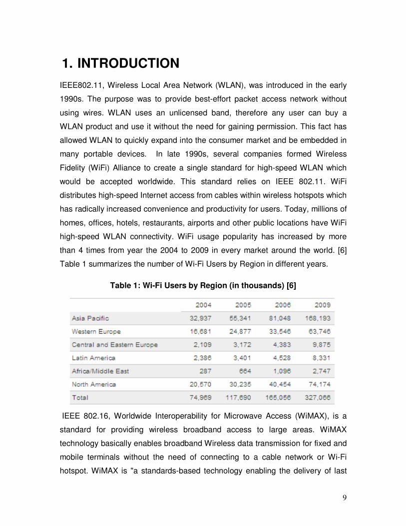
high-speed WLAN connectivity. WiFi usage popularity has increased by more
than 4 times from year the 2004 to 2009 in every market around the world. [6]
Table 1 summarizes the number of Wi-Fi Users by Region in different years.
Table 1: Wi-Fi Users by Region (in thousands) [6]
IEEE 802.16, Worldwide Interoperability for Microwave Access (WiMAX), is a
standard for providing wireless broadband access to large areas. WiMAX
technology basically enables broadband Wireless data transmission for fixed and
mobile terminals without the need of connecting to a cable network or Wi-Fi
hotspot. WiMAX is "a standards-based technology enabling the delivery of last
10
mile wireless broadband access as an alternative to cable and DSL"[8]. WiMAX
provides competitive broadband service to wired ADSL and cable and it can be
easily and cost effectively deployed. IEEE 802.16e, mobile WiMAX, is based on
orthogonal frequency division multiple access (OFDMA) technology and can
support fixed and mobile users simultaneously. In March 2008, WiMAX forum
has projected there will be approximately 133 million WiMAX subscribers by the
year 2012 [2].
WiFi and WiMAX are both IEEE wireless standards that are designed for Internet
Protocol (IP) based applications. WiMAX and WiFi have been designed for
different purposes. WiFi is optimized for a very high speed WLAN while WiMAX
is optimized for a high speed Wireless Wide Area Network (WWAN). By
combining these two standards service providers can offer a more complete high
speed broadband service to more users in different geographical areas. Currently
only few users have WiMAX-enabled devices. They will either need to buy a
compatible device or upgrade their current electronic device (i.e. desktop or
laptop) to enjoy WiMAX capability. Users could also purchase a WiMAX-WiFi
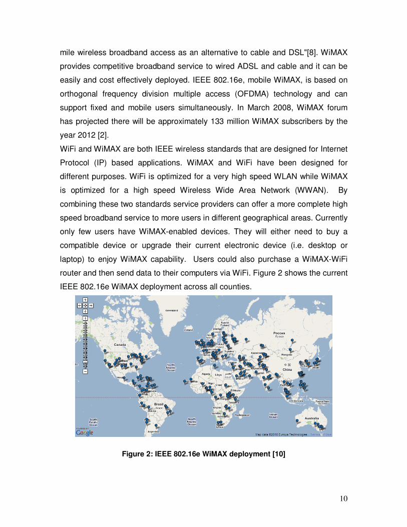
router and then send data to their computers via WiFi. Figure 2 shows the current
IEEE 802.16e WiMAX deployment across all counties.
Figure 2: IEEE 802.16e WiMAX deployment [10]
11
2. WiFi (IEEE 802.11g) BACKGROUND
IEEE 802.11g standard for WLAN, also known as WiFi, operates in the 2.4 GHz
unlicensed band with the maximum data rate of 54 Mbit/s. WiFi uses orthogonal
frequency division multiplexing (OFDM) modulation scheme for data rates of 6, 9,
12, 18, 24, 36, 48, and 54 Mbit/s. For data rates of 5.5 and 11 Mbit/s, it uses
complementary code keying (CCK), and for data rates of 1 and 2 Mbit/s it uses
direct-sequence spread spectrum (DSSS) modulation scheme.
• OFDM is a frequency division multiplexing scheme with the orthogonal
subcarriers modulation method. These subcarriers are spaced close to each
other to carry the data that is divided into parallel data channels. The reason
for choosing the subcarriers orthogonal to each other is to eliminate cross
talk between them.
• CCK “are sets of finite sequences of equal length, such that the number of
pairs of identical elements with any given separation in one sequence is
equal to the number of pairs of unlike elements having the same separation
in the other sequences.”[11]
• DSSS is a modulation scheme that spreads the carrier signal over the full
transmit spectrum. The transmit data is multiplied by a very high frequency
noise signal, which is made of a sequence of pseudorandom ones and
negative ones. The same high frequency noise is used on the receiver side
to demodulate the transmit signal.
WiFi has two types of components, one is a wireless client station and the other
one is an access point (AP). Wireless client station is any user device, such as
computer and laptop, which has wireless network card. AP acts as a bridge
between fixed and wireless network. It organizes and grants access from multiple
wireless stations to the fixed network.
12
3. WiMAX (802.16e) BACKGROUND
WiMAX is a broadband wireless access that supports both fixed and mobile
internet access. It is based on IEEE 802.16 and has maximum data rate of
75Mbits/sec under optimal conditions. WiMAX range covers up to several
kilometers. As a result it can be used for providing wireless broadband across to
cities and countries. It can be used as an alternative last mile solution to cable
and DSL. WiMAX uses scalable orthogonal frequency-division multiple access
(SOFDMA) with 256 sub-carriers. It also supports multiple antennas for better
coverage and better power consumption. Medium access control (MAC) layer of
WiMAX uses a scheduling algorithm for the initial entry of the subscriber stations
(SS) into the network. Then the base station (BS) allocates an access slot to SS
and other subscribers cannot use that slot. The scheduling algorithm is also used
for controlling the bandwidth efficiency and quality of service (QoS) parameters
by changing the time slot duration based on the SS’s application needs. WiMAX
uses 2.3 GHz, 2.5 GHz and 3.5 GHz licensed bands. Since 2007 WiMAX
technology is included in the IMT-2000 set of standards. IMT-2000 standards are
defined by the radio communication sector of the International
Telecommunication Union (ITU-R). As a result any country that recognizes IMT-
2000 standards is able to use to use WiMAX equipments.
4. COMPARISON OF WiFi AND WiMAX
WiMAX uses licensed spectrum and has coverage of many kilometers. WiFi is
designed for local area network coverage in the range of tens of meters and uses
unlicensed band. WiMAX has connection oriented MAC layer while WiFi is
connectionless and uses carrier sense multiple access with collision avoidance
(CSMA/CA) protocol. WiMAX uses scheduling algorithms to control the QoS, but
in WiFi all the users have to compete to get service from an access point (AP)
which is done based on a random interrupt basis. WiFi is more recognized and
13
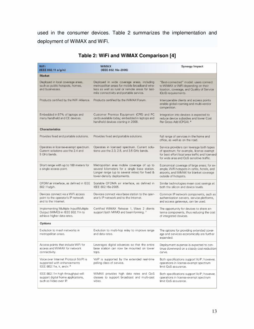
used in the consumer devices. Table 2 summarizes the implementation and
deployment of WiMAX and WiFi.
Table 2: WiFi and WiMAX Comparison [4]
14
5. SIMULATION
4.1) Simulation tool
OPNET is a research oriented network simulation tool. It is a very powerful
software tool that simulates the real world behaviour of wired and wireless
networks. OPNET Modeler version 14.0 was used in this project for
simulating WLAN (WiFi) and WiMAX links.
“The OPNET wireless module and the WLAN model provide high-fidelity
modeling, simulation, and analysis of wireless networks, including the RF
environment, interference, transmitter/receiver characteristics, full protocol
stack, including MAC, routing, higher layer protocols and applications.
Furthermore, the ability to incorporate node mobility and interconnection with
wire-line transport networks provide a rich and realistic modeling
environment.”[12]
“The OPNET WiMAX Specialized Model is available for OPNET Modeler®
Wireless Suite and OPNET Modeler® Wireless Suite for Defense. It supports
the IEEE 802.16-2004 and IEEE 802.16e-2005 standards. It was developed
by OPNET with guidance from prominent industry leaders such as Motorola,
Samsung, Alcatel-Lucent, and France Telecom.”[9]
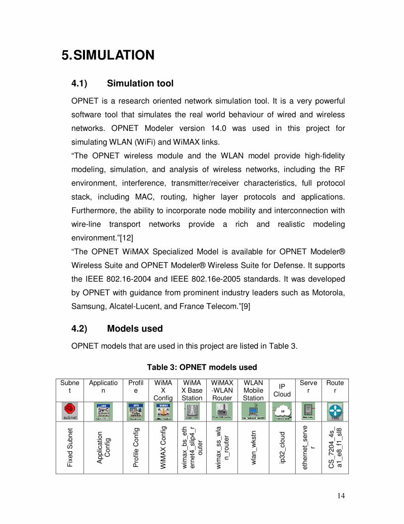
4.2) Models used
OPNET models that are used in this project are listed in Table 3.
Table 3: OPNET models used
Subnet
Application
Profile
WiMAX
Config
WiMAX Base Station
WiMAX-WLAN Router
WLAN Mobile Station
IP Cloud
Server
Router
Fix
ed S
ubnet
Applic
ation
Config
Pro
file
Config
WiM
AX
Config
wim
ax_bs_eth
ern
et4
_slip
4_r
oute
r
wim
ax_ss_w
lan_ro
ute
r
wla
n_w
kstn
ip32_clo
ud
eth
ern
et_
serv
er
CS
_7204_4s_
a1_e8_f1
_sl8
15
4.3) Simulation Setup
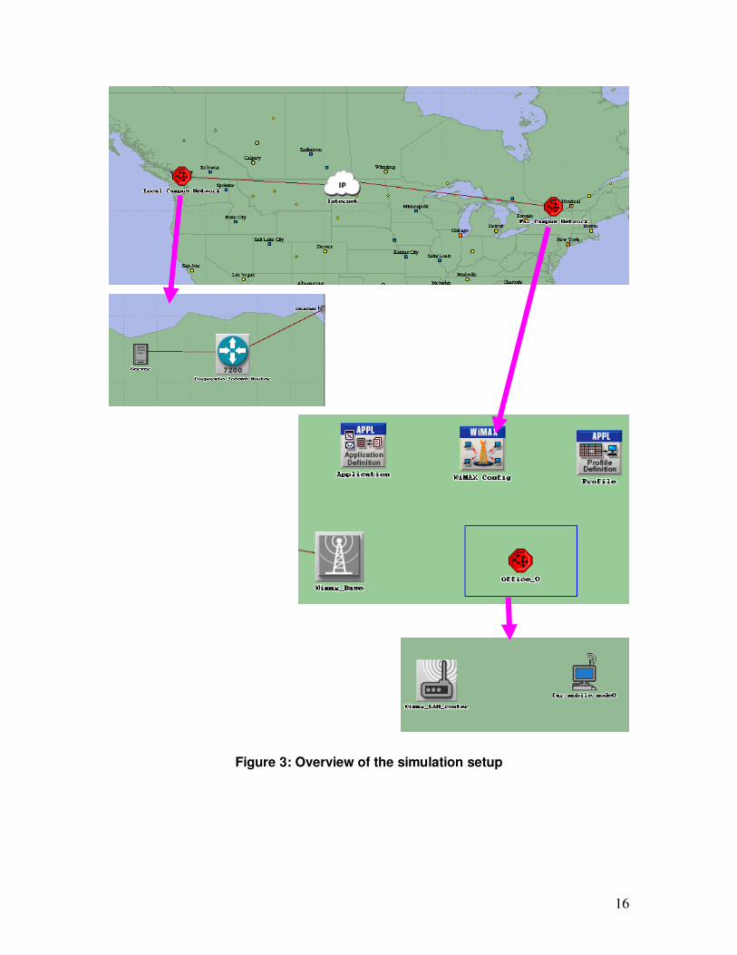
In this project, I used OPNET Modeler 14.0 to simulate MPEG4 Video traffic
over WiMAX-WiFi link. There is a subnet in Vancouver, BC that has a server,
for streaming MPEG4 video, connected to the Internet cloud. There is another
subnet in Ottawa, ON, which receives the MPEG4 video data and distributes
the video content from a WiMAX Base Station to various subscriber station
(SS) subnets around it. The SS subnets are all WiFi enabled and receive the
WiMAX data through their WiMAX-WiFi routers and distribute the video
content over WiFi link to different computers. The general simulation setup is
shown in Figure3.
The MPEG4 video that is used in this project is Matrix III movie. This movie
trace is taken from Will Hrudey’s project [2] and he originally obtained this
video trace from Arizona State University. For this simulation, video
application is chosen in order to overload the Wireless link.
16
Figure 3: Overview of the simulation setup
17
4.4) General Description of Scenarios
There are 3 scenarios in this project. In the first scenario the effect of the
vehicular and pedestrian multipath model effects in WiMAX link are
examined. In the second scenario the maximum simulation range of the
WiMAX link and WiFi link, under optimal conditions are measured. This test is
done with maximum transmit power and “Free Space” path loss model just to
compare the simulation range difference of WiFi and WiMAX. In the third
scenario, the performance of having 2 to 8 WiFi users connected to a single
Access Point (AP) is analyzed.
For all these simulations only up to the first 30 minutes of Matrix III is
streamed from the server. For the first and the second scenarios the 30
minutes simulation time took about 35 minutes of real time. In the third
scenario, with 8 WiFi users, the 30 minutes of simulation time took about 3.5
hours of real time.
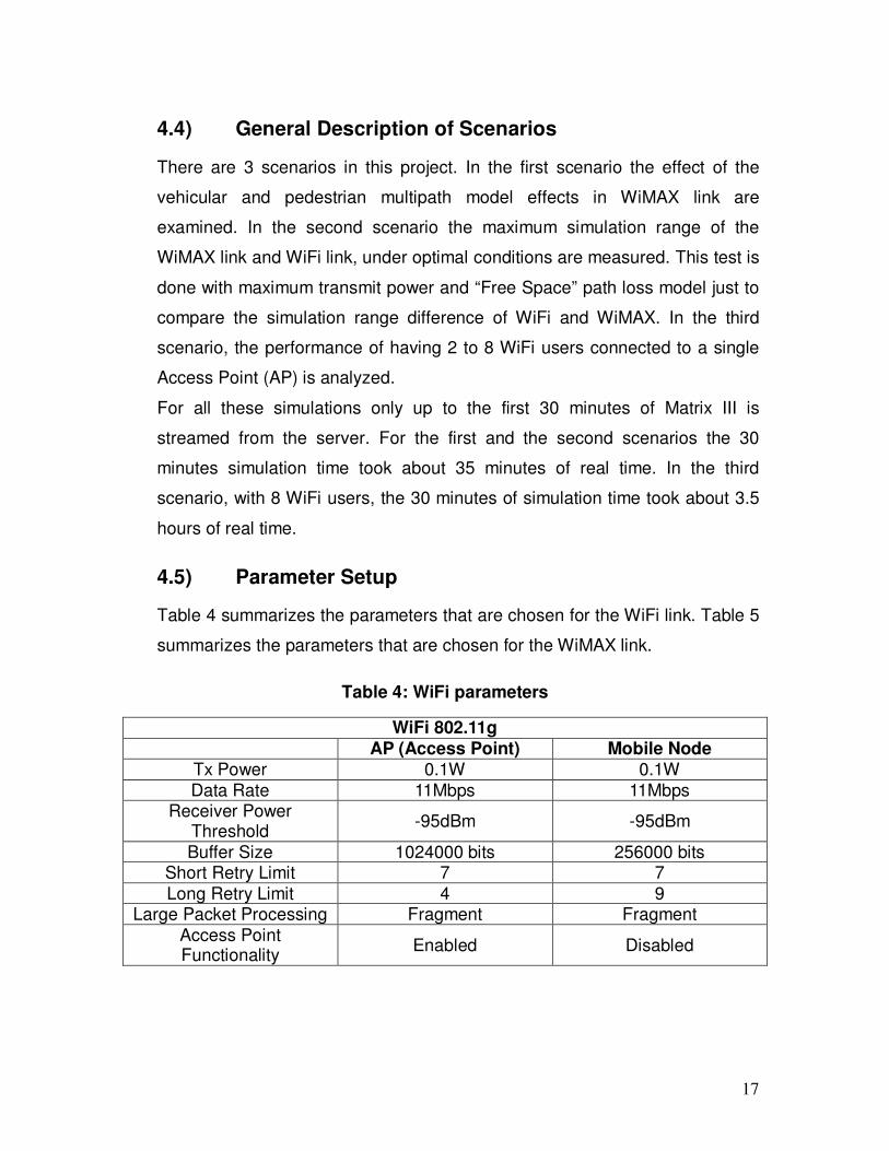
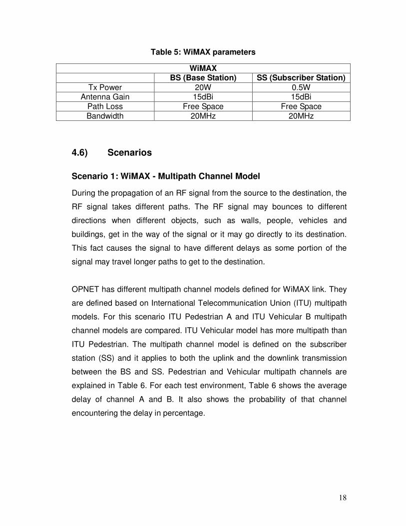
4.5) Parameter Setup
Table 4 summarizes the parameters that are chosen for the WiFi link. Table 5
summarizes the parameters that are chosen for the WiMAX link.
Table 4: WiFi parameters
WiFi 802.11g
AP (Access Point) Mobile Node Tx Power 0.1W 0.1W
Data Rate 11Mbps 11Mbps Receiver Power
Threshold -95dBm -95dBm
Buffer Size 1024000 bits 256000 bits Short Retry Limit 7 7
Long Retry Limit 4 9 Large Packet Processing Fragment Fragment
Access Point Functionality
Enabled Disabled
18
Table 5: WiMAX parameters
WiMAX
BS (Base Station) SS (Subscriber Station)
Tx Power 20W 0.5W Antenna Gain 15dBi 15dBi
Path Loss Free Space Free Space Bandwidth 20MHz 20MHz
4.6) Scenarios
Scenario 1: WiMAX - Multipath Channel Model
During the propagation of an RF signal from the source to the destination, the
RF signal takes different paths. The RF signal may bounces to different
directions when different objects, such as walls, people, vehicles and
buildings, get in the way of the signal or it may go directly to its destination.
This fact causes the signal to have different delays as some portion of the
signal may travel longer paths to get to the destination.
OPNET has different multipath channel models defined for WiMAX link. They
are defined based on International Telecommunication Union (ITU) multipath
models. For this scenario ITU Pedestrian A and ITU Vehicular B multipath
channel models are compared. ITU Vehicular model has more multipath than
ITU Pedestrian. The multipath channel model is defined on the subscriber
station (SS) and it applies to both the uplink and the downlink transmission
between the BS and SS. Pedestrian and Vehicular multipath channels are
explained in Table 6. For each test environment, Table 6 shows the average
delay of channel A and B. It also shows the probability of that channel
encountering the delay in percentage.
19
Table 6: Multipath channel models [13]
Channel A Channel B
Test environment r.m.s. (ns)
P (%)
r.m.s. (ns)
P (%)
Pedestrian 45 40 750 55
Vehicular 370 40 4 000 55
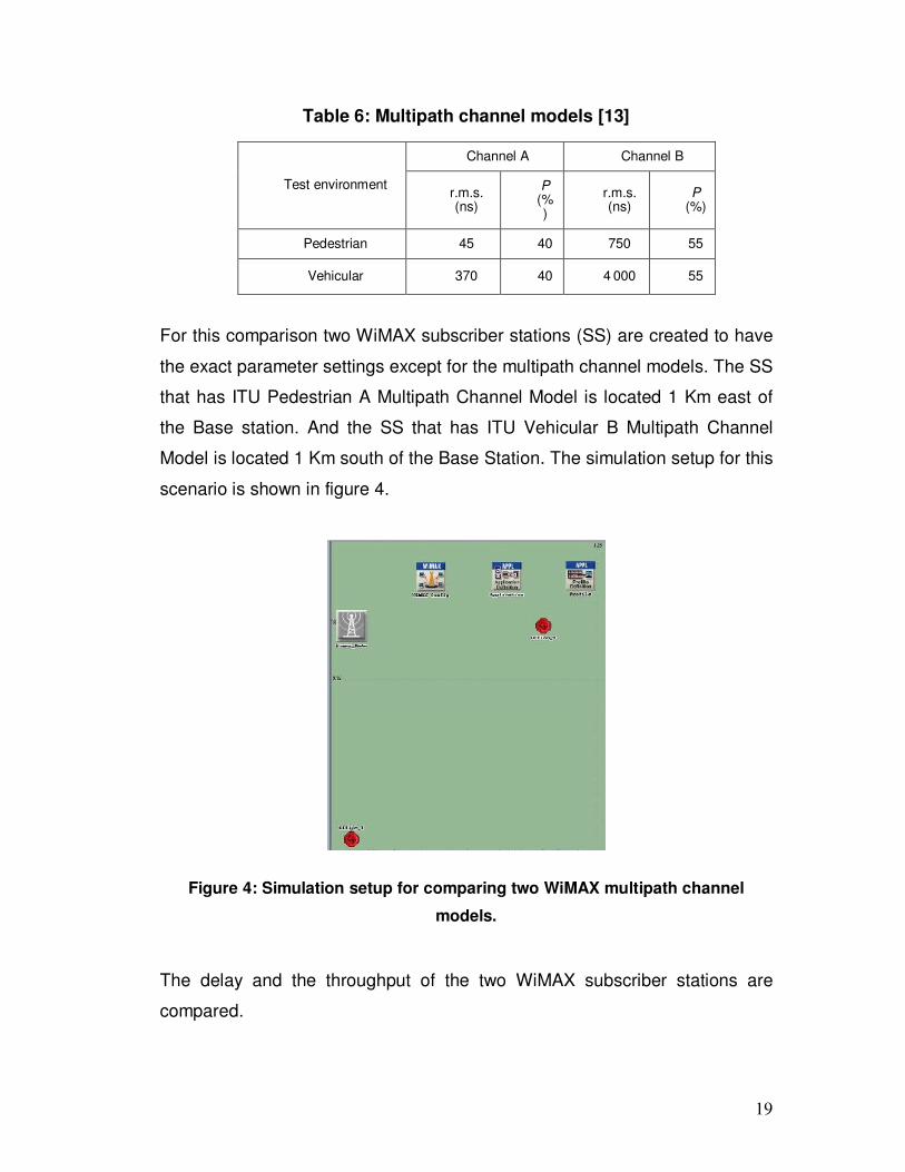
For this comparison two WiMAX subscriber stations (SS) are created to have
the exact parameter settings except for the multipath channel models. The SS
that has ITU Pedestrian A Multipath Channel Model is located 1 Km east of
the Base station. And the SS that has ITU Vehicular B Multipath Channel
Model is located 1 Km south of the Base Station. The simulation setup for this
scenario is shown in figure 4.
Figure 4: Simulation setup for comparing two WiMAX multipath channel
models.
The delay and the throughput of the two WiMAX subscriber stations are
compared.
20
In the subsequent scenarios ITU Pedestrian A Multipath Channel Model is
used.
Scenario 2: WiMAX and WiFi range
The purpose of this scenario is to find the maximum simulation range of
WiMAX and WiFi link with the chosen parameters shown in table 4 and 5.
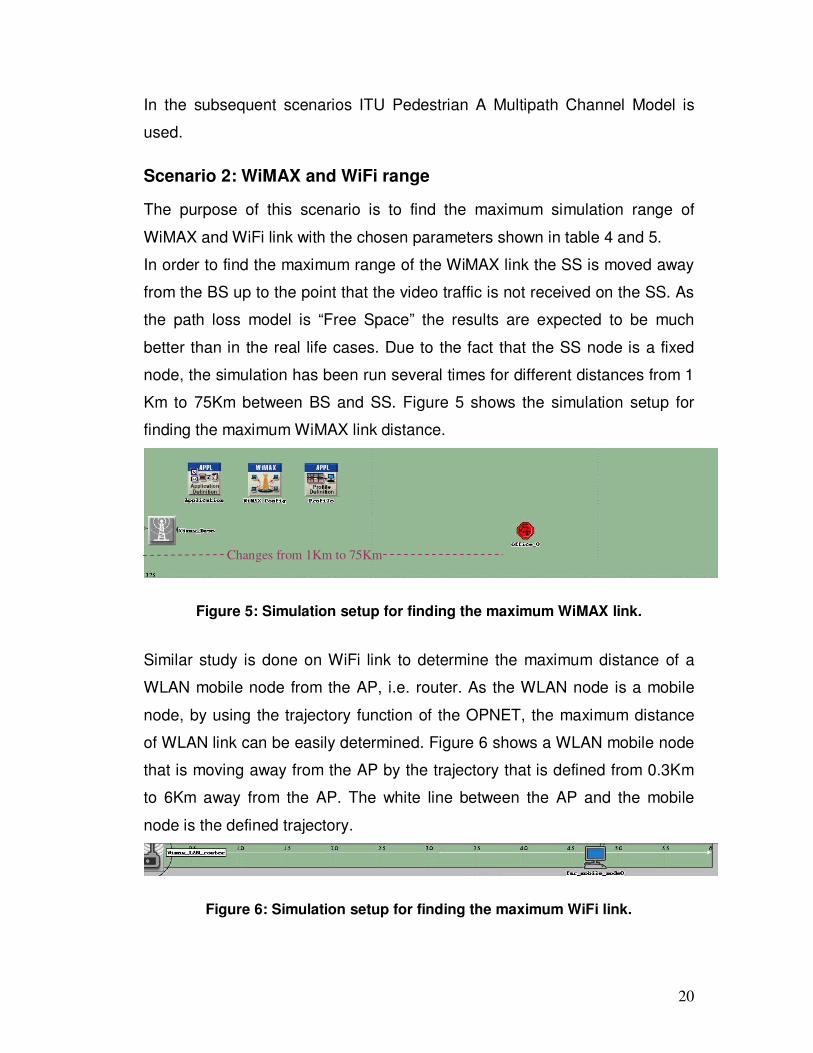
In order to find the maximum range of the WiMAX link the SS is moved away
from the BS up to the point that the video traffic is not received on the SS. As
the path loss model is “Free Space” the results are expected to be much
better than in the real life cases. Due to the fact that the SS node is a fixed
node, the simulation has been run several times for different distances from 1
Km to 75Km between BS and SS. Figure 5 shows the simulation setup for
finding the maximum WiMAX link distance.
Figure 5: Simulation setup for finding the maximum WiMAX link.
Similar study is done on WiFi link to determine the maximum distance of a
WLAN mobile node from the AP, i.e. router. As the WLAN node is a mobile
node, by using the trajectory function of the OPNET, the maximum distance
of WLAN link can be easily determined. Figure 6 shows a WLAN mobile node
that is moving away from the AP by the trajectory that is defined from 0.3Km
to 6Km away from the AP. The white line between the AP and the mobile
node is the defined trajectory.
Figure 6: Simulation setup for finding the maximum WiFi link.
Changes from 1Km to 75Km
21
The received data on the mobile node is monitored while it is moving away
from the AP.
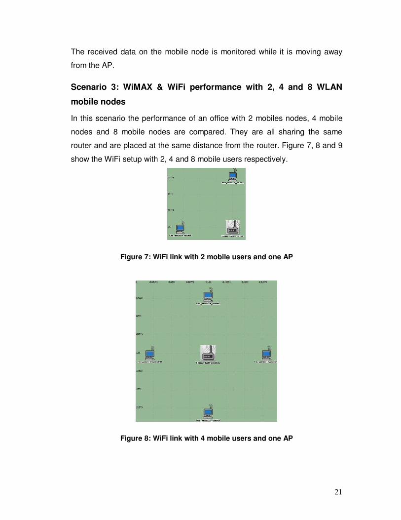
Scenario 3: WiMAX & WiFi performance with 2, 4 and 8 WLAN
mobile nodes
In this scenario the performance of an office with 2 mobiles nodes, 4 mobile
nodes and 8 mobile nodes are compared. They are all sharing the same
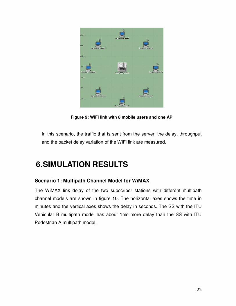
router and are placed at the same distance from the router. Figure 7, 8 and 9
show the WiFi setup with 2, 4 and 8 mobile users respectively.
Figure 7: WiFi link with 2 mobile users and one AP
Figure 8: WiFi link with 4 mobile users and one AP
22
Figure 9: WiFi link with 8 mobile users and one AP
In this scenario, the traffic that is sent from the server, the delay, throughput
and the packet delay variation of the WiFi link are measured.
6. SIMULATION RESULTS
Scenario 1: Multipath Channel Model for WiMAX
The WiMAX link delay of the two subscriber stations with different multipath
channel models are shown in figure 10. The horizontal axes shows the time in
minutes and the vertical axes shows the delay in seconds. The SS with the ITU
Vehicular B multipath model has about 1ms more delay than the SS with ITU
Pedestrian A multipath model.

23
Figure 10: WiMAX delay of SS with different multipath models. Blue delay is for
ITU Vehicular B model and red delay is for ITU Pedestrian A model.
Although the two offices are at the exact same distance from the BS and both
receive the same data with the same transmit power, as expected, the delay is
not the same between the two WiMAX links. Multipath effects cause different
delay in the packets that are being sent over air.
The WiMAX throughput and the average WiMAX throughput of the two SS are
shown in figure 11 and 12 respectively. The horizontal axes shows the time in
minutes and the vertical axes shows the throughput in bits/sec.
Figure 11: Throughput of SS with different multipath models. Red throughput is
for ITU Vehicular B model and blue throughput is for ITU Pedestrian A model.
24
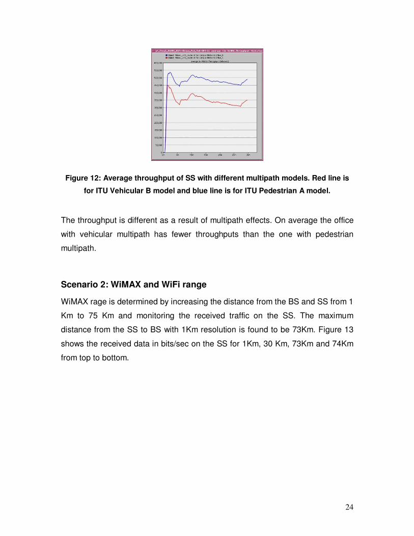
Figure 12: Average throughput of SS with different multipath models. Red line is
for ITU Vehicular B model and blue line is for ITU Pedestrian A model.
The throughput is different as a result of multipath effects. On average the office
with vehicular multipath has fewer throughputs than the one with pedestrian
multipath.
Scenario 2: WiMAX and WiFi range
WiMAX rage is determined by increasing the distance from the BS and SS from 1
Km to 75 Km and monitoring the received traffic on the SS. The maximum
distance from the SS to BS with 1Km resolution is found to be 73Km. Figure 13
shows the received data in bits/sec on the SS for 1Km, 30 Km, 73Km and 74Km
from top to bottom.
25
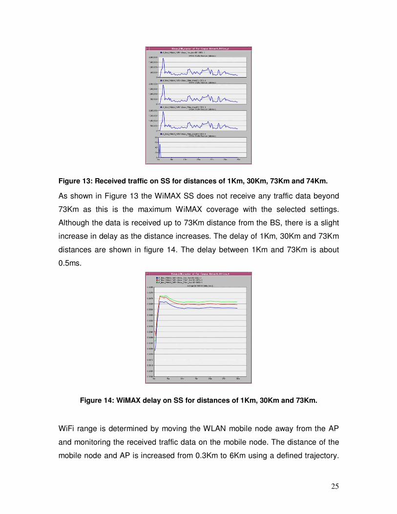
Figure 13: Received traffic on SS for distances of 1Km, 30Km, 73Km and 74Km.
As shown in Figure 13 the WiMAX SS does not receive any traffic data beyond
73Km as this is the maximum WiMAX coverage with the selected settings.
Although the data is received up to 73Km distance from the BS, there is a slight
increase in delay as the distance increases. The delay of 1Km, 30Km and 73Km
distances are shown in figure 14. The delay between 1Km and 73Km is about
0.5ms.
Figure 14: WiMAX delay on SS for distances of 1Km, 30Km and 73Km.
WiFi range is determined by moving the WLAN mobile node away from the AP
and monitoring the received traffic data on the mobile node. The distance of the
mobile node and AP is increased from 0.3Km to 6Km using a defined trajectory.
26
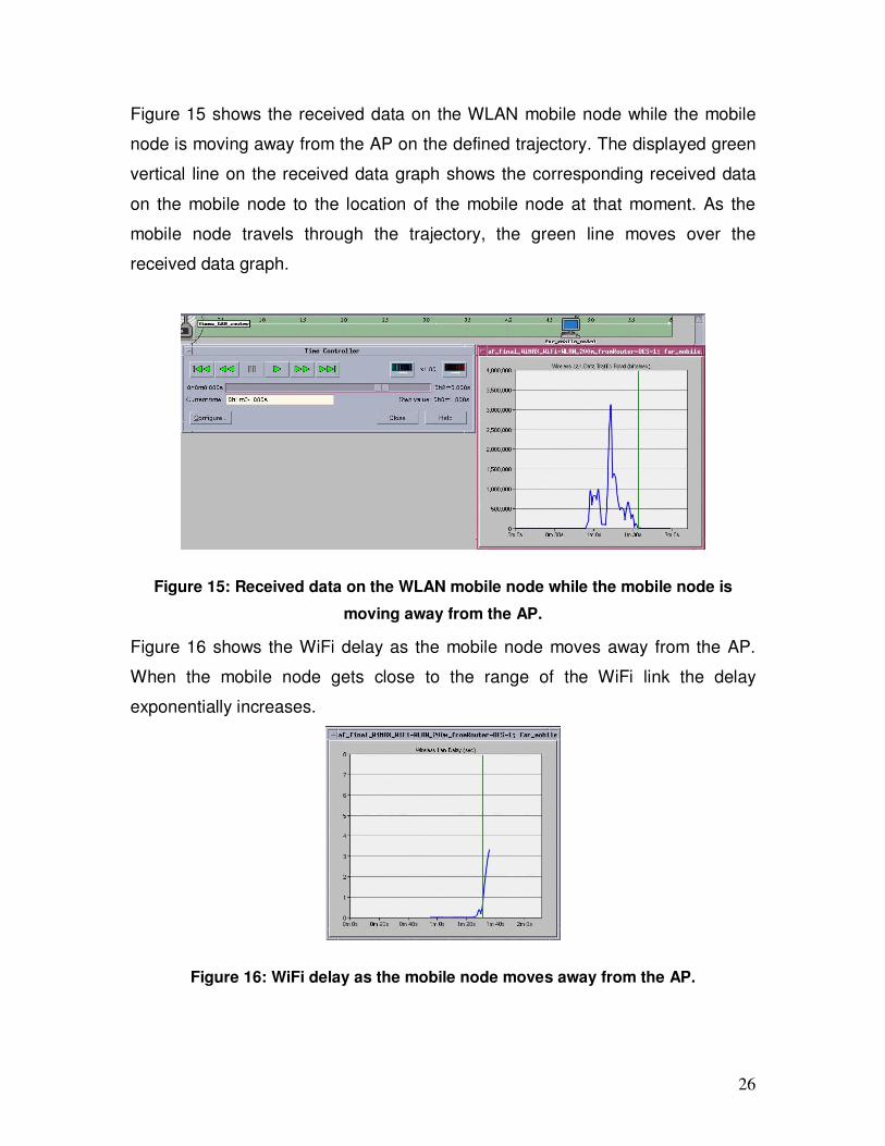
Figure 15 shows the received data on the WLAN mobile node while the mobile
node is moving away from the AP on the defined trajectory. The displayed green
vertical line on the received data graph shows the corresponding received data
on the mobile node to the location of the mobile node at that moment. As the
mobile node travels through the trajectory, the green line moves over the
received data graph.
Figure 15: Received data on the WLAN mobile node while the mobile node is
moving away from the AP.
Figure 16 shows the WiFi delay as the mobile node moves away from the AP.
When the mobile node gets close to the range of the WiFi link the delay
exponentially increases.
Figure 16: WiFi delay as the mobile node moves away from the AP.
27
The maximum simulation range for the WiFi link with the specified settings is
4.6Km.
Scenario 3: WiMAX & WiFi performance with 2, 4 and 8 WLAN mobile
nodes
The WLAN subnet with 2, 4 and 8 mobile nodes has been setup to receive the
MPEG4 movie from the server at the same time. The performances of these
networks have been compared in this scenario.
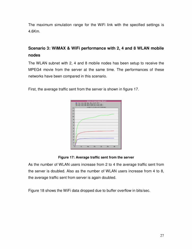
First, the average traffic sent from the server is shown in figure 17.
Figure 17: Average traffic sent from the server
As the number of WLAN users increase from 2 to 4 the average traffic sent from
the server is doubled. Also as the number of WLAN users increase from 4 to 8,
the average traffic sent from server is again doubled.
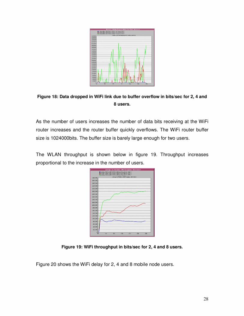
Figure 18 shows the WiFi data dropped due to buffer overflow in bits/sec.
28
Figure 18: Data dropped in WiFi link due to buffer overflow in bits/sec for 2, 4 and
8 users.
As the number of users increases the number of data bits receiving at the WiFi
router increases and the router buffer quickly overflows. The WiFi router buffer
size is 1024000bits. The buffer size is barely large enough for two users.
The WLAN throughput is shown below in figure 19. Throughput increases
proportional to the increase in the number of users.
Figure 19: WiFi throughput in bits/sec for 2, 4 and 8 users.
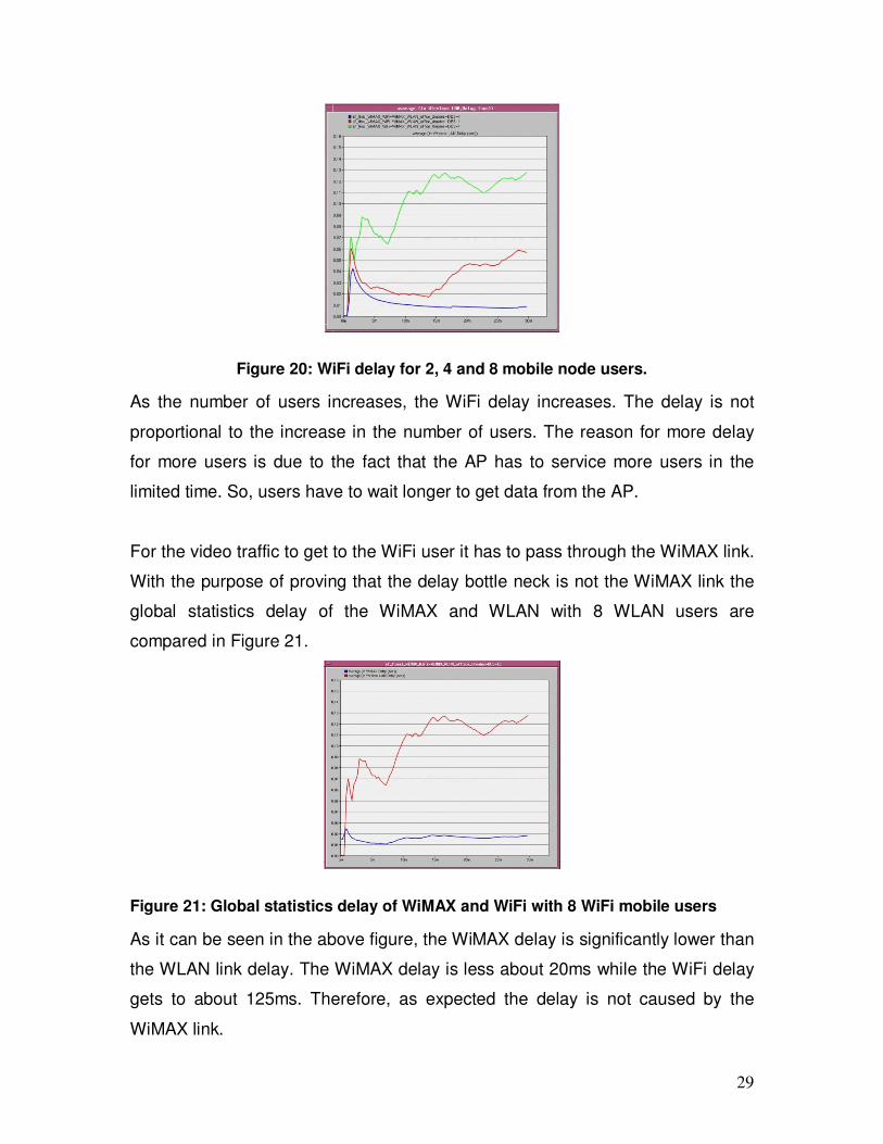
Figure 20 shows the WiFi delay for 2, 4 and 8 mobile node users.
29
Figure 20: WiFi delay for 2, 4 and 8 mobile node users.
As the number of users increases, the WiFi delay increases. The delay is not
proportional to the increase in the number of users. The reason for more delay
for more users is due to the fact that the AP has to service more users in the
limited time. So, users have to wait longer to get data from the AP.
For the video traffic to get to the WiFi user it has to pass through the WiMAX link.
With the purpose of proving that the delay bottle neck is not the WiMAX link the
global statistics delay of the WiMAX and WLAN with 8 WLAN users are
compared in Figure 21.
Figure 21: Global statistics delay of WiMAX and WiFi with 8 WiFi mobile users
As it can be seen in the above figure, the WiMAX delay is significantly lower than
the WLAN link delay. The WiMAX delay is less about 20ms while the WiFi delay
gets to about 125ms. Therefore, as expected the delay is not caused by the
WiMAX link.
30
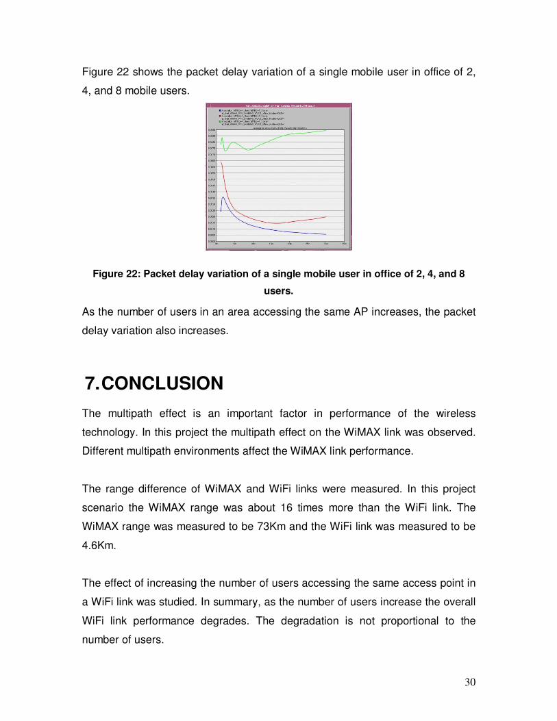
Figure 22 shows the packet delay variation of a single mobile user in office of 2,
4, and 8 mobile users.
Figure 22: Packet delay variation of a single mobile user in office of 2, 4, and 8
users.
As the number of users in an area accessing the same AP increases, the packet
delay variation also increases.
7. CONCLUSION
The multipath effect is an important factor in performance of the wireless
technology. In this project the multipath effect on the WiMAX link was observed.
Different multipath environments affect the WiMAX link performance.
The range difference of WiMAX and WiFi links were measured. In this project
scenario the WiMAX range was about 16 times more than the WiFi link. The
WiMAX range was measured to be 73Km and the WiFi link was measured to be
4.6Km.
The effect of increasing the number of users accessing the same access point in
a WiFi link was studied. In summary, as the number of users increase the overall
WiFi link performance degrades. The degradation is not proportional to the
number of users.
31
8. FUTURE WORK
The path loss model was chosen to be “Free Space” for this project. This is not a
realistic path loss. In order to get more realistic results a more realistic path loss
model effects on the WiMAX link should be analyzed.
The main focus of the third scenario of this project was on the overloading the
WiFi link and seeing the link performance effect of it. The same exercise should
be done on the WiMAX link.
9. REFERENCES
1. H. Labiod, H. Afifi and C. Santis, Wi-Fi, Bluetooth, Zigbee and WiMAX,
Dordrecht, Netherland: Springer, 2007, Chapter 2 and Chapter 5.
2. W. Hrudey and Lj. Trajkovic, “Streaming video content over IEEE
802.16/WiMAX broadband access,” OPNETWORK 2008, Washington,
DC, Aug. 2008.
3. Intel, Understanding Wi-Fi and WiMAX as metro-access solutions, White
paper [Online]. Available: http://www.rclient.com/PDFs/IntelPaper.pdf
(Accessed: March 2010).
4. Motorola and Intel, WiMAX and WiFi Together: Deployment Models and
User Scenarios, White paper [Online]. Available:
http://www.motorola.com/staticfiles/Business/Solutions/Industry%20Soluti
ons/Service%20Providers/Wireless%20Operators/Wireless%20Broadban
d/wi4%20WiMAX/_Document/StaticFile/WiMAX_and_WiFI_Together_Dep
loyment_Models_and_User_Scenarios.pdf (Accessed: March 2010).
5. B. Gi Lee and S. Choi, Broadband Wireless Access and Local Networks:
Mobile WiMAX and WiFi, Artech House, 2008, Chapter 2 and Chapter 11.
6. “Wi-Fi Gaining Traction,” BusinessWeek, Pyramid Research, Mar. 5,
2010. [Online]. Available:
http://www.businessweek.com/technology/tech_stats/wifi051003.htm
(Accessed: April 2010).
32
7. P. Sharma, “Facts About WiMAX And Why Is It “The Future of Wireless
Broadband””, TechPluto, Jun. 20, 2009 [Online]. Available:
http://www.techpluto.com/wimax-in-detail/ (Accessed: April 2010).
8. “WiMAX”, Wikipedia, [Online]. Available:
http://en.wikipedia.org/wiki/WiMAX (Accessed: April 2010).
9. “WiMAX (802.16) specialized model”, OPNET, [Online]. Available:
http://www.opnet.com/WiMAX/index.html (Accessed: March 2010).
10. “WiMAX Deployments”, WiMAX MAPS, Apr. 14, 2010 [Online]. Available:
http://www.wimaxmaps.org/ (Accessed: April 2010).
11. “Complementary code keying”, Wikipedia, [Online]. Available:
http://en.wikipedia.org/wiki/Complementary_code_keying (Accessed: April
2010).
12. “WLAN (802.11)”, OPNET, [Online]. Available:
http://www.opnet.com/support/des_model_library/WLAN80211.html
(Accessed: April 2010).
13. ITU ITU-R M.1225, ““Guidelines for evaluations of radio transmission
technologies for IMT-2000”, 1997 [Online]. Available:
http://www.itu.int/dms_pub/itu-r/oth/0A/0E/R0A0E00000C0001MSWE.doc
(Accessed: April 2010).
33
10. ORIGINAL PROJECT IDEA
My original project idea was to understand and simulate IEEE1588 standard,
which is a precision time protocol used in wireless technology. Due to the fact
that I was not able to find an OPNET model for this protocol, I decided to change
my topic. Creating an OPNET model for this protocol was considered, but due to
the complexity of it and having a limited time for this course this activity is
postponed to a later time.
10.1 IEEE1588 ABSTRACT
Wireless technology is transforming the mobile networks to an all packet
network. Currently, the clock synchronization of the mobile backhaul is done
by GPS and TDM. As a result of the network transformation, the mobile
backhaul is progressing to IP and Ethernet to have more bandwidth and better
performance. The mobile backhauls that require very precise timing will have
to depend on packets for their timing, and the difficulty is due to the fact that
Ethernet is asynchronous. New approaches/standards defining clock recovery
mechanisms over packet Networks, such as IEEE 1588v2, have been
proposed. IEEE 1588, also called Precision Time Protocol (PTP), is a standard
protocol for accurate timing and frequency over IP networks. In this protocol,
the packets carry time stamp information between the client and the server.
My goal for this project is to understand the IEEE 1588 protocol and simulate it
using OPNET in a mobile network and find the timing accuracy of this protocol
with various traffic loads.
10.2 IEEE1588 INTRODUCTION
Mobile networks are changing to an all packet network and using IP and
Ethernet for higher bandwidth and better performance. It is required to be able
to exchange data within a specified time and synchronize all the network
34
nodes very precisely. Therefore, a very precise timing will have to depend on
Ethernet packet which is asynchronous. IEEE 1588 is a standard protocol for
accurate synchronization of clocks used in network communication systems
and defines precise clock recovery mechanism over packet Networks. Using
this protocol, systems that have different clock precisions and resolutions and
are from different manufacturers, can be synchronized together in the sub-
microsecond accuracy. “Existing time synchronization protocols such as NTP
and SNTP do not achieve the required synchronization accuracy or the
convergence speed. Others, such as SynUTC from the Technical University in
Vienna, were not accepted on the market.” [5]
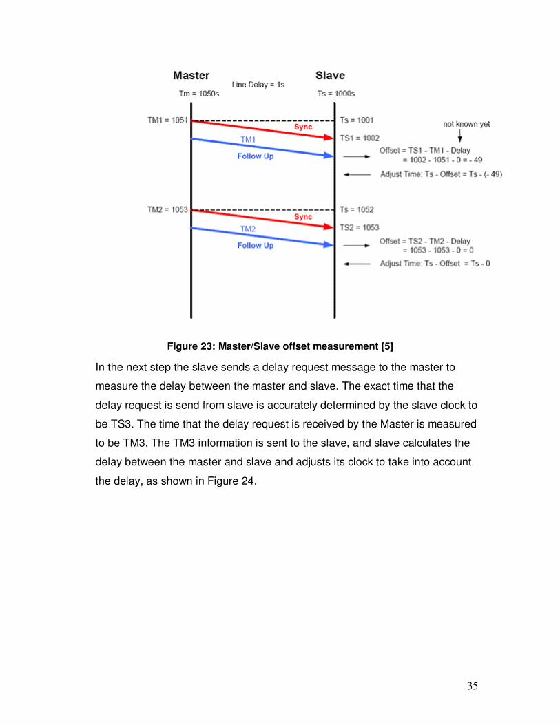
In the IEEE1588 protocol, all the clocks in a network synchronize to one clock
of the network, which is considered to be the most precise one of all. The most
precise clock is going to be the master and the clock that is synchronizing to it,
is called the slave. The synchronization between the master and slave is done
by exchanging synchronization messages. The first step is that the master
transmits a unique synchronization (SYNC) message to its slave every 2
seconds. The slave measures the time the sync message was received (TS1).
Then master sends a follow up message containing the time that the sync
message was sent (TM1). This way the offset time between the master and
slave is corrected as shown in the Figure 23. Slave time is adjusted by the
offset.
35
Figure 23: Master/Slave offset measurement [5]
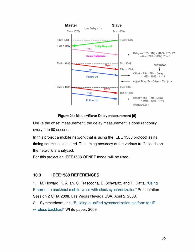
In the next step the slave sends a delay request message to the master to
measure the delay between the master and slave. The exact time that the
delay request is send from slave is accurately determined by the slave clock to
be TS3. The time that the delay request is received by the Master is measured
to be TM3. The TM3 information is sent to the slave, and slave calculates the
delay between the master and slave and adjusts its clock to take into account
the delay, as shown in Figure 24.
36
Figure 24: Master/Slave Delay measurement [5]
Unlike the offset measurement, the delay measurement is done randomly
every 4 to 60 seconds.
In this project a mobile network that is using the IEEE 1588 protocol as its
timing source is simulated. The timing accuracy of the various traffic loads on
the network is analyzed.
For this project an IEEE1588 OPNET model will be used.
10.3 IEEE1588 REFERENCES
1. M. Howard, K. Allan, C. Frascogna, E. Schwartz, and R. Datta, “Using
Ethernet to backhaul mobile voice with clock synchronization” Presentation
Session 2 CTIA 2008, Las Vegas Nevada USA, April 2, 2008.
2. Symmetricom, Inc. “Building a unified synchronization platform for IP
wireless backhaul” White paper, 2009.
37
3. J. Eidson, “IEEE-1588 Standard for a Precision Clock Synchronization
Protocol for Networked Measurement and Control Systems”, Agilent
Technologies, October 10, 2005.
4. K. Lee, “IEEE1588TM-2002 Standard for a Precision Clock
Synchronization Protocol for Networked Measurement and Control Systems,”
National Institute of Standards and Technology. 5 August 2002, updated: 25
February 2010 [Online] Available: http://ieee1588.nist.gov/ (Accessed:
February 2010).
5. D. S. Mohl, "IEEE 1588 - Precise time synchronization as the basis for real
time applications in automation," IEEE 1588. [Online] Available:
http://www.ieee1588.com (Accessed February 2010).
6. IXXAT Automation GmbH, “IEEE 1588 PTP Introduction”, IXXAT, 2004-
2010. [Online] Available: http://www.ixxat.com/introduction_ieee_1588_en.html
(Accessed February 2010).
![ENSC427:CommunicationNetworks,Spring2012 ... › ~ljilja › ENSC427 › Spring12 › Projects › team12 › ENSC...References’! [1]A.Zaballos,G.Corral,I.Serra,J.Abella,"TestingNetworkSecurity%](https://img.pdfslide.us/doc/110x75/5f0ec6637e708231d440e03f/ensc427communicationnetworksspring2012-a-ljilja-a-ensc427-a-spring12.jpg)


](https://img.pdfslide.us/doc/110x75/5446b812afaf9f5d178b471e/negotiation-seminar-farzin-fardiss-day-1391-6-pp-mode1.jpg)
