Embed Size (px)
Citation preview

SM 8051 1000 Technology Drive, Pittsburgh, PA 15219 645 Russell Street, Batesburg, SC 29006
AF-902/AF-904 Audio Frequency Track Circuit System
Field Maintenance Manual
♦ Description ♦ Installation and Adjustment
♦ Maintenance and Troubleshooting

AF-902/AF-904 Audio Frequency Track Circuit System Field Maintenance Manual
Copyright 2019 SM 8051 Rev. 7 March 2019

AF-902/AF-904 Audio Frequency Track Circuit System Field Maintenance Manual
Copyright 2019 SM 8051 Rev. 7, March 2019 i
Proprietary Notice This document and its contents are the property of Hitachi Rail STS USA (hereinafter STS USA). This document has been furnished to you on the following conditions: no right or license under any patents or any other proprietary right in respect of this document or its content is given or waived in supplying this document. This document or its content are not to be used or treated in any manner inconsistent with the rights of STS USA, or to its detriment, and are not to be copied, reproduced, disclosed to others, or disposed of except with the prior written consent of STS USA.
Important Notice STS USA constantly strives to improve our products and keep our customers apprised of changes in technology. Following the recommendations contained in the attached service manual will provide our customers with optimum operational reliability. The data contained herein purports solely to describe the product, and does not create any warranties. Within the scope of the attached manual, it is impossible to take into account every eventuality that may arise with technical equipment in service. Please consult your local STS USA Account Executive in the event of any irregularities with our product. We expressly disclaim liability resulting from any improper handling or use of our equipment, even if these instructions contain no specific indication in this respect. We strongly recommend that only approved STS USA spare parts be used as replacements.

AF-902/AF-904 Audio Frequency Track Circuit System Field Maintenance Manual
Copyright 2019 SM 8051 Rev. 7, March 2019 ii
Revision History Rev. Date Nature of Revision 0.0 10/9/98 Initial Issue
1.0 2/19/99 Revised per Shanghai and QA comments
1.1 4/20/99 Revised for submittal to Copenhagen
2.0 7/20/01 Revised for submittal to Copenhagen
2.1 1/11/02 Revised for submittal to Copenhagen
3.0 5/12/03 Revised to include Section 9 Tektronix Instructions
3.1 June 27, 2003 Revisions per ECO 139841-3A and 139734-6
4.0 July 24, 2003 Revisions per FTR
5.0 March 8, 2004 Revised to update preventive maintenance procedures
6.0 March 14, 2008
Revised per ECO 140056-1. Revised Subsection 1.3.3.1 and Figure 1-6, and added Figure 1-7 through Figure 1-9 to cover “O”, “I”, and direct injection track cable bond applications. Included references to Figure 1-6, Figure 1-7, and Figure 1-8 in Subsection 1.3.3.2. Revised Figure 1-8. Replaced the last sentence with two sentences. Also modified Figure 2-4 to show coupling unit for cab signaling loop and changed “SER” to “Relay Room”. Incorporated proof comments.
7.0 March 2019 Hitachi Rail STS Branding

AF-902/AF-904 Audio Frequency Track Circuit System Field Maintenance Manual
Copyright 2019 SM 8051 Rev. 7, March 2019 iii
Table of Contents 1. General Information ................................................................................................................... 1-1 1.1. Introduction ....................................................................................................................... 1-1 1.2. Safety ............................................................................................................................... 1-2 1.3. Physical Description ......................................................................................................... 1-3 1.3.1. Cardfile ............................................................................................................................. 1-3 1.3.2. Printed Circuit Boards....................................................................................................... 1-5 1.3.3. Wayside Components .................................................................................................... 1-11 1.4. Specifications ................................................................................................................. 1-14 1.4.1. Track Carrier Frequencies ............................................................................................. 1-14 1.4.2. Cab Signal Data Transmission ....................................................................................... 1-15 1.4.3. Track MICROLOK II Data Transmission ............................................................................ 1-15 1.4.4. Data from AF-902/904 to MICROLOK II ............................................................................ 1-19 1.4.5. Track Circuit ................................................................................................................... 1-20 1.4.6. Control Cardfile............................................................................................................... 1-20 1.4.7. Coupling Unit .................................................................................................................. 1-20 1.4.8. 350 or 500 MCM Bond ................................................................................................... 1-20 1.5. References ..................................................................................................................... 1-20 2. Typical Applications ................................................................................................................... 2-1 2.1. Mainline Track Circuits ..................................................................................................... 2-2 2.1.1. Track Circuit ID and Cab Signal Transmission ................................................................ 2-2 2.2. Yard Track Circuits ........................................................................................................... 2-4 2.3. Cab-Only Transmission in Crossovers ............................................................................. 2-5 2.4. Train Detection Only in Double Crossover ....................................................................... 2-7 2.5. System Connection Diagrams .......................................................................................... 2-7 3. Functional Description .............................................................................................................. 3-1 3.1. Introduction ....................................................................................................................... 3-1 3.2. Wayside to Train Message Formation ............................................................................. 3-1 3.2.1. Data Routing ..................................................................................................................... 3-1 3.2.2. Data Protocol .................................................................................................................... 3-2 3.2.3. Message Commands, Functions, and Formation ............................................................ 3-3 3.3. FSK Signal Transmission ................................................................................................. 3-3 3.3.1. Message Verification ........................................................................................................ 3-4 3.3.2. Equipment Room to Rails ................................................................................................. 3-5 3.4. Train Detection ................................................................................................................. 3-6 3.5. Monitoring and Fail-Over .................................................................................................. 3-7 3.5.1. MICROLOK II Monitoring.................................................................................................. 3-7 3.5.2. AF-902/904 Monitoring ..................................................................................................... 3-7 3.5.3. Fail-Over (AF-902 System Only) ...................................................................................... 3-9 4. Front Panel Menu Operation .................................................................................................... 4-1 4.1. Introduction ....................................................................................................................... 4-1 4.2. Front Panel Displays, Controls, and Operation ................................................................ 4-1 4.2.1. Displays ............................................................................................................................ 4-1 4.2.2. Controls ............................................................................................................................ 4-3 4.2.3. Front Panel Operation ...................................................................................................... 4-3 4.3. Menu Hierarchy ................................................................................................................ 4-4 4.3.1. Menu Access .................................................................................................................... 4-4 4.3.2. Password Protection......................................................................................................... 4-5 4.3.3. Cardfile Configuration ....................................................................................................... 4-5 4.3.4. Key Repeat Delay ............................................................................................................. 4-5 4.3.5. Time-out ........................................................................................................................... 4-5 4.3.6. Main Menu ........................................................................................................................ 4-5 4.3.7. Blocking Speed Menu....................................................................................................... 4-5 4.3.8. Display Menu .................................................................................................................... 4-6 4.3.9. Events Menu ..................................................................................................................... 4-6

AF-902/AF-904 Audio Frequency Track Circuit System Field Maintenance Manual
Copyright 2019 SM 8051 Rev. 7, March 2019 iv
4.3.10. Configuration Menu .......................................................................................................... 4-7 5. Installation and Adjustment ...................................................................................................... 5-1 5.1. Introduction ....................................................................................................................... 5-1 5.2. Recommended Test Equipment ....................................................................................... 5-1 5.3. Serial Link Configuration .................................................................................................. 5-1 5.4. Vital Parallel Output Terminations .................................................................................... 5-2 5.5. Initial Power Checks ......................................................................................................... 5-2 5.6. Tuning Procedure ............................................................................................................. 5-2 5.7. Calibration Procedure ....................................................................................................... 5-2 5.7.1. Testing Codes and Abbreviations .................................................................................... 5-3 5.7.2. Test Equipment and Tools ............................................................................................... 5-4 5.7.3. Transmit Power Adjustments ........................................................................................... 5-4 5.7.4. Setup Overview ................................................................................................................ 5-5 5.8. AF-902/904 Track Circuit System Setup and Test ........................................................... 5-6 5.8.1. AF-902/904 350 or 500 MCM Track Circuit Setup ........................................................... 5-8 5.9. Test Documentation and Data Sheets ........................................................................... 5-13 6. Preventive Maintenance ............................................................................................................ 6-1 6.1. Introduction ....................................................................................................................... 6-1 6.2. Importance of Preventive Maintenance ............................................................................ 6-1 6.2.1. Received Signal Level ...................................................................................................... 6-2 6.2.2. Error Code Monitoring ...................................................................................................... 6-6 6.2.3. Variance ........................................................................................................................... 6-7 6.3. Preventive Maintenance Tasks ........................................................................................ 6-8 6.3.1. Initial Preventive Maintenance Tasks ............................................................................... 6-8 6.3.2. Equipment Cleaning Procedure ..................................................................................... 6-10 6.3.3. Track Circuit Inspection .................................................................................................. 6-12 6.3.4. Track Circuit Checks ...................................................................................................... 6-13 7. Troubleshooting ......................................................................................................................... 7-1 7.1. Introduction ....................................................................................................................... 7-1 7.2. Approach to Troubleshooting ........................................................................................... 7-1 7.3. Troubleshooting Procedures ............................................................................................ 7-2 7.3.1. Fault Symptoms ............................................................................................................... 7-2 7.3.2. Error Code Observations .................................................................................................. 7-4 7.4. PCB Front Panel Indicators and Controls ........................................................................ 7-9 7.4.1. AF-902/904 Controller PCB .............................................................................................. 7-9 7.4.2. AF-902/904 Auxiliary PCB ................................................................................................ 7-9 7.4.3. AF-902/904 Power Supply PCB ..................................................................................... 7-10 8. Corrective Maintenance ............................................................................................................ 8-1 8.1. Introduction ....................................................................................................................... 8-1 8.2. Replacement Repair ......................................................................................................... 8-1 8.2.1. AF-902/904 PCB Replacement ........................................................................................ 8-1 8.2.2. Coupling Unit Replacement .............................................................................................. 8-2 8.2.3. Bond Replacement ........................................................................................................... 8-5 8.3. Verification of System Repair ........................................................................................... 8-5 9. Tektronix Setup Procedure ....................................................................................................... 9-1 10. Parts List .................................................................................................................................... 10-1 10.1. Track Circuit Cardfile Overview ...................................................................................... 10-1 10.2. Track Circuit Cardfile ...................................................................................................... 10-1 10.3. Cardfile Motherboard Direction Relays ........................................................................... 10-3 10.4. AF-902 and AF-904 Cardfile PCBs ................................................................................ 10-9 10.5. Coupling Units ................................................................................................................ 10-9 11. Technical Support .................................................................................................................... 11-1 11.1. RAIL Team and Technical Support ................................................................................ 11-1
AF-902/AF-904 Audio Frequency Track Circuit System Field Maintenance Manual
Copyright 2019 SM 8051 Rev. 7, March 2019 v
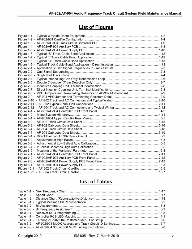
List of Figures
Figure 1-1 - Typical Wayside Room Equipment ....................................................................................... 1-2 Figure 1-2 - AF-902/904 Cardfile Configuration ....................................................................................... 1-4 Figure 1-3 - AF-902/AF-904 Track Circuit Controller PCB ....................................................................... 1-6 Figure 1-4 - AF-902/AF-904 Auxiliary PCB .............................................................................................. 1-8 Figure 1-5 - AF-902/AF-904 Power Supply PCB .................................................................................... 1-10 Figure 1-6 - Typical “S” Track Cable Bond Application .......................................................................... 1-12 Figure 1-7 - Typical “I” Track Cable Bond Application ............................................................................ 1-12 Figure 1-8 - Typical “O” Track Cable Bond Application .......................................................................... 1-13 Figure 1-9 - Typical Track Cable Bond Application – Direct Injection .................................................... 1-13 Figure 2-1 - Application of Cab Signal Frequencies to Track Circuits ...................................................... 2-3 Figure 2-2 - Cab Signal Sequencing ........................................................................................................ 2-3 Figure 2-3 - Single Rail Track Circuit ....................................................................................................... 2-4 Figure 2-4 - Typical Interlocking Cab-Only Transmission Loop ............................................................... 2-6 Figure 2-5 - Double Crossover (Train Detection Only) ............................................................................. 2-7 Figure 2-6 - Inductive Coupling Unit, Terminal Identification .................................................................... 2-8 Figure 2-7 - Direct Injection Coupling Unit, Terminal Identification .......................................................... 2-8 Figure 2-8 - VPO Jumpers and Terminating Resistors on AF-902 Motherboard ..................................... 2-9 Figure 2-9 - AF-904 VPO Jumper and Terminating Resistors Detail ....................................................... 2-9 Figure 2-10 - AF-902 Track and AC Connectors and Typical Wiring ..................................................... 2-10 Figure 2-11 - AF-902 Typical Serial Link Connections ........................................................................... 2-11 Figure 2-12 - AF-904 Track and AC Connections and Typical Wiring ................................................... 2-12 Figure 4-1 - AF-902/AF-904 Controller PCB Front Panel ......................................................................... 4-2 Figure 4-2 - Menu System Hierarchy ...................................................................................................... 4-11 Figure 5-1 - AF-902/904 Upper Cardfile Rear Views................................................................................ 5-5 Figure 5-2 - AF-902 Track Circuit Data Sheet ........................................................................................ 5-15 Figure 5-3 - AF-902 Cab Loop Data Sheet ............................................................................................. 5-16 Figure 5-4 - AF-904 Track Circuit Data Sheet ........................................................................................ 5-18 Figure 5-5 - AF-904 Cab Loop Data Sheet ............................................................................................. 5-19 Figure 6-1 - Direct Injection AF 902 Track Circuit .................................................................................... 6-2 Figure 6-2 - Adjustment at High Ballast .................................................................................................... 6-3 Figure 6-3 - Adjustment at Low Ballast Auto Calibration .......................................................................... 6-5 Figure 6-4 - If Ballast Becomes High Auto Calibration ............................................................................. 6-5 Figure 6-5 - Meaning of the ‘Variance’ Parameter ................................................................................... 6-8 Figure 7-1 - AF-902/AF-904 Controller PCB Front Panel ....................................................................... 7-11 Figure 7-2 - AF-902/AF-904 Auxiliary PCB Front Panel ......................................................................... 7-12 Figure 7-3 - AF-902/AF-904 Power Supply PCB Front Panel ................................................................ 7-13 Figure 8-1 - AF-902/AF-904 Power Supply PCB ...................................................................................... 8-3 Figure 10-1 - AF-902 Track Circuit Cardfile ........................................................................................... 10-5 Figure 10-2 - AF-904 Track Circuit Cardfile ........................................................................................... 10-7
List of Tables Table 1-1 - Next Frequency Chart .......................................................................................................... 1-17 Table 1-2 - Speed Chart ......................................................................................................................... 1-17 Table 1-3 - Distance Chart (Representative Distance) ........................................................................... 1-18 Table 3-1 - Typical Message Bit Representation ...................................................................................... 3-2 Table 3-2 - Bit Assignments ..................................................................................................................... 3-3 Table 3-3 - Bit Frequency Assignment ..................................................................................................... 3-3 Table 3-4 - Receiver NCO Programming ................................................................................................. 3-8 Table 4-1 - Controller PCB LED Mapping ................................................................................................ 4-1 Table 5-1 - Entering AF-902/904 Restricted Menu For Setup .................................................................. 5-6 Table 5-2 - AF-902/904 MLOK Address and Track Circuit ID Settings .................................................... 5-7 Table 5-3 - AF-902/904 350 or 500 MCM Tuning Instructions ................................................................. 5-8

AF-902/AF-904 Audio Frequency Track Circuit System Field Maintenance Manual
Copyright 2019 SM 8051 Rev. 7, March 2019 vi
Table 5-4 - Coupling Unit (Nominal Capacitance Setting) ........................................................................ 5-9 Table 5-5 - AF-902/904 350 or 500 MCM Calibration Procedure ............................................................. 5-9 Table 5-6 - Rail Current Settings (350 MCM, 500 MCM, and Cab Loop Circuits) .................................. 5-10 Table 5-7 - Rail Current Settings (Direct Injection Circuits) .................................................................... 5-11 Table 5-8 - AF-902/904 Cab Loop Track Circuit Setup .......................................................................... 5-11 Table 5-9 - AF-902/904 Direct Injection Track Circuit Setup .................................................................. 5-12 Table 6-1 - Common AF-902 Error Codes ............................................................................................... 6-6 Table 6-2 - Key Preventive Maintenance Actions ................................................................................... 6-10 Table 7-1 - Basic Troubleshooting Concepts ........................................................................................... 7-1 Table 7-2 - Troubleshooting ..................................................................................................................... 7-3 Table 7-3 - AF-902 Critical Error Codes ................................................................................................... 7-4 Table 7-4 - All AF-902 Error Codes .......................................................................................................... 7-8 Table 8-1 - AF-902/904 Tuning Summary ................................................................................................ 8-6 Table 8-2 - AF-902/904 Calibration Summary .......................................................................................... 8-6 Table 9-1 - Tektronix Setup Procedure .................................................................................................... 9-2 Table 10-1 - AF-902/904 Track Circuit Cardfiles .................................................................................... 10-1 Table 10-2 - Track Circuit Cardfile Parts List ......................................................................................... 10-1 Table 10-3 - Motherboard Direction Relays Parts List ............................................................................ 10-4 Table 10-4 - Cardfile PCBs Parts List .................................................................................................... 10-9 Table 10-5 - Coupling Units Parts List .................................................................................................... 10-9

AF-902/AF-904 Audio Frequency Track Circuit System Field Maintenance Manual
Copyright 2019 SM 8051 Rev. 7, March 2019 1-1
1. General Information 1.1. Introduction
This service manual is intended for use with both the AF-902 and AF-904 digital Frequency Shift Keyed (FSK) track circuit controller systems. The AF-902 system includes redundant equipment for fail-over operation. The AF-904 system is not redundant. When describing features common to both systems, the term “AF-902/904” is used.
The AF-902/904 system is part of the wayside portion of an Automatic Train Control (ATC) system. It is the primary communications interface between the wayside and the carborne equipment. The AF-902/904 system provides both train detection and transmission of digital cab signaling data for the Automatic Train Protection (ATP) function of an ATC system. Figure 1-1 shows the equipment that is contained in a typical wayside room.
To perform its primary functions of train detection and cab signaling, the AF-902/904 system encodes data from the track logic processor on the wayside and puts it on the track where it is picked up and decoded by the carborne ATP equipment. This data is used for line speed, target speed, track length, grade, direction, door control, next frequency, and coupling/uncoupling information. Vital track logic is performed by the Track MICROLOK II system. Interlocking logic and control of switch machines and signals are performed by the Interlocking MICROLOK II. Non-vital logic is performed by Non-Vital Logic Emulator (NVLE) units. Routing is performed automatically by the train ID (through the wayside communications system), from the local control panel, by fleeting, or from central control.
The AF-902/904 system comprises the trackside equipment and processing equipment within the signal equipment room. The trackside equipment consists of track coupling units, wire bonds, and track loops.
As shown in Figure 1-1 the processing equipment for an AF-902 system contains the Primary and Backup circuits. The MICROLOK II units and NVLE units are also duplicated for fail-over conditions.
Transit Lines requiring multiple track circuits can be equipped with a maximum of 12 AF-902/904 track circuits per track MICROLOK II system.

AF-902/AF-904 Audio Frequency Track Circuit System Field Maintenance Manual
Copyright 2019 SM 8051 Rev. 7, March 2019 1-2
CENTRALCONTROL FACILITY
CENTRALCONTROL FACILITY
VITAL
NON-VITAL
VITAL
SWITCHMACHINES ANDSIGNALS
AF-902
VITAL SERIAL
LINK
TRACKCONNECTIONS(350 OR500 MCMBONDS)
VITALPARALLELOUTPUTS
(where used)
NON-VITAL LOOP
S SREMOTENVLE
LOCALNVLES M
SLOCAL
PCS
M S TWCA/B
LOCALCONTROL
PANEL
S
S
M
INTERLOCKINGMICROLOK II
A/B
S
M
TRACKMICROLOK II
A/B
RELAYS
S
SPRIMARY
BACKUP
LEGEND: S = SLAVE M = MASTER NVLE = NON-VITAL LOGIC EMULATOR
Figure 1-1 - Typical Wayside Room Equipment
1.2. Safety
Read and thoroughly understand this manual before attempting any of the procedures listed. Pay particular attention to:
WARNING
and
CAUTION
statements that appear throughout this manual. Caution statements indicate conditions that could cause damage to equipment. Warning statements indicate conditions that could cause physical harm, serious injury, or loss of life. Always observe standard precautions familiar to trained electrical technicians. Always adhere to all safety regulations stipulated by the railroad.
AF-902/AF-904 Audio Frequency Track Circuit System Field Maintenance Manual
Copyright 2019 SM 8051 Rev. 7, March 2019 1-3
1.3. Physical Description
1.3.1. Cardfile
The AF-902/904 cardfile chassis, which is compatible with a 19-inch wide AF rack, houses electronic PCBs. This hardware is in the equipment room. It requires a 115 Vac ± 10% at 50/60 Hz (nominal) input power.
This rack-mounted cardfile shares design features with the STS USA's MicroTrax Coded Track Circuit and Microoab Cab Signal Systems, which include integral PCB front edge control/display panels, menu-driven alphanumeric LED displays, and 9-pin serial data ports.
Figure 1-2 shows the layout of the AF-902/904 cardfiles. Each cardfile contains ten PCBs, all of which plug into a motherboard mounted on the back of the cardfile. The motherboard is a printed circuit board that provides connections between the PCBs. Connectors for each PCB are mounted on the motherboard. When the PCBs are installed in the cardfile, PCB edge connectors slide into the motherboard connectors. In the AF-902 system, the cardfile contains two track circuits. Each track circuit contains five PCBs. These five PCBs are configured to provide redundant Primary and Backup units.
The Primary unit consists of:
• One track circuit controller PCB
• One auxiliary PCB
• Half of a power supply PCB
Likewise, the Backup track circuit unit consists of:
• One track circuit controller PCB
• One auxiliary PCB
• Half of a power supply PCB
One power supply PCB, with two independent supply systems, is common to the Primary and Backup sections of one track circuit.

AF-902/AF-904 Audio Frequency Track Circuit System Field Maintenance Manual
Copyright 2019 SM 8051 Rev. 7, March 2019 1-4
The AF-904 cardfile has the same PCB layout, but does not provide redundant track circuit units. Instead, the ten PCBs are configured as four separate track circuits. Each track circuit consists of:
• One track circuit controller PCB
• One auxiliary PCB
• Half of a power supply PCB
• One power supply PCB, with two independent supply systems, is common to two separate track circuits.
TRACK CIRCUIT # 1 TRACK CIRCUIT # 2 TRACK CIRCUIT # 3 TRACK CIRCUIT # 4
TRACK CIRCUIT # 2TRACK CIRCUIT # 1AF-902:
AF-904:
POWER SUPPLYN12360501
ONOFF
+15V-15V+5V+15V-15V LE
FTPO
WER
SUP
PLY
GND
OFF
RIGH
TPO
WER
SUPP
LYLE
FTPO
WER
SUP
PLY
POWER SUPPLYN12360501
0
ON
0
XMFR
+5V+15V-15V
XMFR
XMFR
+5V
ON
+15V-15V+5V
ON
+15V
OFF
-15V
0
GND
0
OFF
GND-15V+15V+5V-15V+15V+5V
+5V
XMFR
-15V
RIGH
TPO
WER
SUPP
LY
+15V+5V
GND
AUXILIARYBOARD
N12360401
CPS ACTIVE
ON-LINE
SELF
PARTNERHEALTH
U-LOK COMM
BLOCK SPEED SET
LEVEL
DATATRACKCLEAR
P1
P2RECEIVER
INPUT
+12V
+5VVITAL
OUTPUTS
BANDPASS FILTER
ANALOG GROUND
+44V
SYSTEM GROUND
+
-
CPS 500Hz
TRANSMITTEROUTPUT
AUXILIARYBOARD
N12360401
CPS ACTIVE
ON- LINE
SELF
PARTNERHEALTH
U-LOK COMM
BLOCK SPEED SET
LEVEL
DATATRACKCLEAR
P1
P2RECEIVER
INPUT
+12V
+5VVITAL
OUTPUTS
BANDPASS FILTER
ANALOG GROUND
+44V
SYSTEM GROUND
+
-
CPS 500Hz
TRANSMITTEROUTPUT
AUXILIARYBOARD
N12360401
CPS ACTIVE
ON-LINE
SELF
PARTNERHEALTH
U-LOK COMM
BLOCK SPEED SET
LEVEL
DATATRACKCLEAR
P1
P2RECEIVER
INPUT
+12V
+5VVITAL
OUTPUTS
BANDPASS FILTER
ANALOG GROUND
+44V
SYSTEM GROUND
+
-
CPS 500Hz
TRANSMITTEROUTPUT
AUXILIARYBOARD
N12360401
CPS ACTIVE
ON-LINE
SELF
PARTNERHEALTH
U-LOK COMM
BLOCK SPEED SET
LEVEL
DATATRACKCLEAR
P1
P2RECEIVER
INPUT
+12V
+5VVITAL
OUTPUTS
BANDPASS FILTER
ANALOG GROUND
+44V
SYSTEM GROUND
+
-
CPS 500Hz
TRANSMITTEROUTPUT
UP
DOWN
ADJMODE
AUX 1
PRESS TORESET
IN RESETWHEN LIT
ESCAPE
STATUSLEDS 2
1
DIR.W
E
DEBUGPORT
TRK CKTCTRLR
N123603-01
DIAGPORT
UP
DOWN
ADJMODE
AUX 1
PRESS TORESET
IN RESETWHEN LIT
ESCAPE
STATUSLEDS 2
1
DIR.W
E
DEBUGPORT
TRK CKTCTRLR
N123603-01
DIAGPORT
UP
DOWN
ADJMODE
AUX 1
PRESS TORESET
IN RESETWHEN LIT
ESCAPE
STATUSLEDS 2
1
DIR.W
E
DEBUGPORT
TRK CKTCTRLR
N123603-01
DIAGPORT
UP
DOWN
ADJMODE
AUX 1
PRESS TORESET
IN RESETWHEN LIT
ESCAPE
STATUSLEDS 2
1
DIR.W
E
DEBUGPORT
TRK CKTCTRLR
N123603-01
DIAGPORT
EN TER AUX 2 EN TER AUX 2 EN TER AUX 2 EN TER AUX 2
Figure 1-2 - AF-902/904 Cardfile Configuration

AF-902/AF-904 Audio Frequency Track Circuit System Field Maintenance Manual
Copyright 2019 SM 8051 Rev. 7, March 2019 1-5
1.3.2. Printed Circuit Boards
The AF-902/904 cardfile PCBs are modular in design, which allows for easy removal and replacement should repair become necessary. Since the stored programming is on EEPROMs mounted on the cardfile backplane, replacement of any logic PCB may be done with little reprogramming. A calibration procedure should be performed to verify proper track circuit operation. Adjustments are also made via jumpers on the cardfile backplane so that a system reset is not required with changeout of the track interface circuitry.
All power is supplied to the PCBs via the backplane motherboard. 115 Vac ± 10% at 50/60 Hz (nominal) power feeds to the power supply PCB which, in turn, supplies the controller and auxiliary circuitry with the required voltages.
CAUTION
This system operates directly from the AC mains. Use caution when working near the backplane or on the power supply, and especially when working on a PCB mounted on an extender board.
Both Primary units within the AF-902 cardfile are powered from the same AC power feed. Likewise, both Backup units are powered from the same second AC feed.
1.3.2.1. Track Circuit Controller PCB
Figure 1-3 shows the front panel of the track circuit controller PCB. (The location of these PCBs in the cardfile is shown in Figure 1-2.) The heart of the track circuit controller is a Motorola MC68HC16Z1 Complementary Metal Oxide Semiconductor (CMOS) Microcontroller. Many of the support functions necessary for the make-up of a microprocessor-based device are internally incorporated in the 68HC16's System Integration Module (SIM). In addition to the SIM, the 68HC16 contains several on-chip peripherals that reduce the PCB's chip count. This contributes greatly to the compactness of the AF-902/904 unit.
The end user is provided with:
• Two alphanumeric displays. These are used to monitor the data used in setup and operation of the track circuit. The upper display is red and the lower display is green.
• Four momentary contact Single Pole Double Throw (SPDT) toggle switches. These switches are used for inputting data required for setup conditions.

AF-902/AF-904 Audio Frequency Track Circuit System Field Maintenance Manual
Copyright 2019 SM 8051 Rev. 7, March 2019 1-6
• Five LEDs. These supply additional information, as described in Section 4.2.1.
• A PC-compatible serial port. A female DB9 connector provides an RS-232 DTE port used for detailed monitoring and diagnostics of the AF-902/904 logic and memory.
• Background Debugging Port. This port is used for direct control of the 68HC16 microprocessor. It is primarily for factory use.
UP
DOWN
ADJMODE
AUX 1
PRESS TORESET
IN RESETWHEN LIT
ESCAPE
STATUSLEDS 2
1
DIR.W
E
DEBUGPORT
TRK CKTCTRLR
N123603-01
DIAGPORT
ALPHANUMERICLED DISPLAYS
MOTOROLABACKGROUNDDEBUG PORT
(FACTORY USE ONLY)
CONFIGURATION SETUPSWITCHES
MOMENTARY CONTACTSWITCHES
(SPRING RETURN TO CENTER)
SYSTEM MONITORLEDS
SYSTEM RESETPUSHBUTTON
9-PIN PORTFOR
PORTABLE PC(RE-232DTE)
EN TER AUX 2
Figure 1-3 - AF-902/AF-904 Track Circuit Controller PCB

AF-902/AF-904 Audio Frequency Track Circuit System Field Maintenance Manual
Copyright 2019 SM 8051 Rev. 7, March 2019 1-7
1.3.2.2. Auxiliary PCB
Figure 1-4 shows the front panel of the auxiliary PCB. (The location of these PCBs in the cardfile is shown in Figure 1-2.) The auxiliary PCB contains both the power amplifier for track data transmissions and the front end part of the receiver for incoming track signals, as well as the Conditional Power Supply (CPS) subsystem. Relays on this PCB are used for fail-over to the alternate subsystem.
The following are on the auxiliary PCB front panel:
• Eight LEDs. These indicate the status of various key parameters in a readily interpreted format.
• Eleven maintenance test points. These provide accessible test points for voltage and signals that cover the controller and auxiliary PCBs.

AF-902/AF-904 Audio Frequency Track Circuit System Field Maintenance Manual
Copyright 2019 SM 8051 Rev. 7, March 2019 1-8
AUXILIARYBOARD
N12360401
CPS ACTIVE
ON-LINE
SELF
PARTNERHEALTH
U-LOK COMM
BLOCK SPEED SET
LEVEL
DATATRACKCLEAR
P1
P2RECEIVER
INPUT
+12V
+5VVITAL
OUTPUTS
BANDPASS FILTER
ANALOG GROUND
+44V
SYSTEM GROUND
+
-
CPS 500Hz
TRANSMITTEROUTPUT
SYSTEM MONITORLEDS
MAINTENANCETEST POINTS
Figure 1-4 - AF-902/AF-904 Auxiliary PCB

AF-902/AF-904 Audio Frequency Track Circuit System Field Maintenance Manual
Copyright 2019 SM 8051 Rev. 7, March 2019 1-9
1.3.2.3. Power Supply PCB
Figure 1-5 shows the front panel of the power supply PCB. (The location of these PCBs in the cardfile is shown in Figure 1-2.) The single power supply PCB in each AF-902/904 system provides both subsystems with regulated operating power for internal components. This PCB interfaces standard AC commercial power to the system. For safety purposes, a solde-side cover is provided to reduce the risk of electrical shock when removing the PCB from the cardfile.
WARNING Dangerous voltages are exposed when operating the power supply PCB on an extender board. Use extreme caution when working near exposed terminals. Failure to do so could result in serious physical injury or loss of life.
The front panel has the following features:
• Six LEDs. There are three LEDs for left track circuit power monitoring and three for right track circuit power monitoring.
• Two separate power switches. The upper power switch energizes the two PCBs to the immediate right of each power supply PCB. The lower power switch energizes the two PCBs to the immediate left of each power supply PCB. Note that these switches are locking-lever type switches that must be pulled out to toggle.
• 12 voltage test points. There are four DC and two AC test points for each subsystem supply.
Note that each subsystem is driven from a separate AC feed for improved system reliability.

AF-902/AF-904 Audio Frequency Track Circuit System Field Maintenance Manual
Copyright 2019 SM 8051 Rev. 7, March 2019 1-10
POWER SUPPLYN12360501
ONOFF
+15V-15V+5V+15V-15V LE
FTPO
WER
SUP
PLY
GND
OFF
0
ON
0
XMFR
+5V+15V-15V
+5V
XMFR
-15V
RIGH
TPO
WER
SUPP
LY
+15V+5V
GND
LOCKINGSUBSYSTEM
POWER SWITCH
AC POWERTEST POINTS
POWERMONITOR
LEDS
DC POWERTEST POINTS
LOCKINGSUBSYSTEM
POWER SWITCH
POWERMONITOR
LEDS
DC POWERTEST POINTS
Figure 1-5 - AF-902/AF-904 Power Supply PCB

AF-902/AF-904 Audio Frequency Track Circuit System Field Maintenance Manual
Copyright 2019 SM 8051 Rev. 7, March 2019 1-11
1.3.3. Wayside Components
The required supporting trackside components for the AF-902/904 system are the track coupling units, wire bonds, and track loops.
From the equipment room, track leads of up to several kilometers total loop length connect the trackside coupling units to the direction relays. The track leads are twisted pairs with an intrinsic impedance (Zo) of approximately 100 ohms.
1.3.3.1. Track Coupling Units
Figure 1-6, Figure 1-7, Figure 1-8, and Figure 1-9 show track coupling units for “S”, “I”, “O”, and direct injection track cable bond applications. AF-902/904 coupling units interface the track signals with the cardfile receiver and transmitter circuits. They also provide for tuning to the track circuit carrier frequency. The track coupling units are housed in weather tight enclosures, and consist of two totally independent and isolated signal coupling circuits. Each circuit has its own transformer and a jumper-adjusted capacitor bank for frequency tuning as required for the track loops.
The dimensions of the track coupling unit are 16”W x 8”H x 10”L (40.64 cm x 20.32 cm x 25.4 cm). The unit can be mounted on the wayside ground base or on a wall.
In the figures referenced above, the coupling units and track circuits are connected through twisted pair #14 cabling that measures a maximum of 6,000 ft. (1,830 m).

AF-902/AF-904 Audio Frequency Track Circuit System Field Maintenance Manual
Copyright 2019 SM 8051 Rev. 7, March 2019 1-12
23 FT. (7 M) 23 FT. (7 M)
COLLAR FOR CABLES
LOOP CABLE
BOND CABLE
BOND AND LOOP CABLE MOUNTING
TRACK ‘A’ & ’B’ COUPLING UNIT
TRACK ‘B’ & ‘C’ COUPLING UNIT
TRACK ‘A’ TRACK ‘B’ TRACK ‘C’
350 OR 500 MCM 350 OR 500 MCM
MAX. 15 FT.ONE-TURNCOUPLING
LOOP(#6 AWG)
AF-90XTRACK
CIRCUIT“B”
MAX.6,000 FT.
TWO TWISTED-PAIRS (#14 AWG)
TWO TWISTED-PAIRS (#14 AWG)
Rx ‘B’ Tx ‘A’ Rx ‘C’ Tx ‘B’
TRAFFIC
Figure 1-6 - Typical “S” Track Cable Bond Application
TRACK ‘A’ & ‘B’ COUPLING UNIT
TRACK ‘B’ & ‘C’ COUPLING UNIT
TRACK ‘A’ TRACK ‘B’ TRACK ‘C’
350 OR 500 MCM
MAX. 15 FT.ONE-TURNCOUPLING
LOOP(#6 AWG)
AF-90XTRACK
CIRCUIT“B”
MAX.6,000 FT. TWO TWISTED-PAIRS (#14 AWG)
TWO TWISTED-PAIRS (#14 AWG)
NEUTRAL CONNECTIONTO SUBSTATION
NEUTRAL CONNECTIONTO SUBSTATION
11.5 FT. (3.5M)TRAFFIC
Tx ‘A’ Rx ‘B’ Tx ‘B’ Rx ‘C’
Figure 1-7 - Typical “I” Track Cable Bond Application

AF-902/AF-904 Audio Frequency Track Circuit System Field Maintenance Manual
Copyright 2019 SM 8051 Rev. 7, March 2019 1-13
TRACK ‘A’ TRACK ‘C’TRACK ‘B’
TRACK ‘A’ & ‘B’ COUPLING UNIT
TRACK ‘B’ & ‘C’ COUPLING UNIT
MAX. 15 FT.ONE-TURNCOUPLING
LOOP(#6 AWG)
AF-90XTRACK
CIRCUIT“B”
MAX.6,000 FT. TWO TWISTED-PAIRS (#14 AWG)
TWO TWISTED-PAIRS (#14 AWG)
11.5 FT. (3.5M)
NEUTRALCONNECTION
NEUTRALCONNECTION
350 OR 500 MCM
INSULATEDJOINTS
TO SUBSTATION(OPTIONAL)
Tx ‘A’ Rx ‘B’
11.5 FT. (3.5M)
350 OR 500 MCM
INSULATEDJOINTS
TO SUBSTATION(OPTIONAL)
Tx ‘B’ Rx ‘C’
TRAFFIC
Figure 1-8 - Typical “O” Track Cable Bond Application
TRACK ‘A’ COUPLING UNIT TRACK ‘A’ COUPLING UNIT
TRACK ‘A’
AF-90XTRACK
CIRCUIT
MAX.6,000 FT.
MAX. 300 FT. MAX. 300 FT.
TWO TWISTED-PAIRS (#14 AWG)
TWO TWISTED-PAIRS (#14 AWG)
INSULATEDJOINTS SIGNAL RAIL
RETURN RAIL
TRACK WIRES (TYP. #6 AWG) TRACK WIRES (TYP. #6 AWG)
TRAFFIC
Figure 1-9 - Typical Track Cable Bond Application – Direct Injection 1.3.3.2. 350 or 500 MCM Bonds
Signals and messages in the rails are transmitted to and received from the AF-902/904 cardfiles via cabling type bonds known as “350MCM” or “500MCM” bonds. The actual bond type that is used for an application depends on the length of the train. (Although similar, only the 350 MCM bonds are addressed for the purpose of this discussion.)

AF-902/AF-904 Audio Frequency Track Circuit System Field Maintenance Manual
Copyright 2019 SM 8051 Rev. 7, March 2019 1-14
AF-902/904 track coupling units are tuned to the carrier frequency and provide impedance matching to/from the track.
The 350 MCM (Thousand Circular Mils) bond consists of a few meters of 350 MCM cable connected between the two rails in an “S”, “I”, or “O” shape, with the end of the “S”, “I”, or “O” bonded to each rail. See Figure 1-6, Figure 1-7, and Figure 1-8. One-turn track loops are inside the upper and lower parts of the “S” and inside the “O” part. As Figure 1-7 shows, the track loops are on both sides of the “I” bond.
“S” and “I” bonds are used in areas where there are no insulated joints that define the track circuit boundaries. “O” bonds are used in areas where an insulated joint is used in each rail to define the track circuit boundaries. The AF-902/904 must be connected so that the track signal is always injected into the track end farthest away from the end that the train is entering. The direction relays mounted on the rear of the cardfile will switch the transmission direction based upon the data in the message received from the vital wayside controller.
1.4. Specifications
1.4.1. Track Carrier Frequencies Odd Frequencies Even Frequencies
F0 9.5 kHz F1 10.5 kHz F2 11.5 kHz F3 12.5 kHz F4 13.5 kHz F5 14.5 kHz F6 15.5 kHz F7 16.5 kHz Frequency Shift: ±200 Hz Modulation: BFSK carrier Baud Rate: 200 BPS

AF-902/AF-904 Audio Frequency Track Circuit System Field Maintenance Manual
Copyright 2019 SM 8051 Rev. 7, March 2019 1-15
1.4.2. Cab Signal Data Transmission Signal Message: 37 data bits, 8 header bits, 16 Cyclic Redundancy
Check (CRC) validation bits
Protocol: Synchronous, bit oriented (similar to Synchronous Data Link Control [SDLC])
Encoding: NRZI Bits Name Function 12 Track Circuit ID Identification of present track circuit (0 to
4095)
1 Primary/Backup Identification of which controller is providing the message
2 Direction Train direction of travel
3 Next Frequency Carrier frequency of the next track circuit
7 Distance to Go Distance of target speed
4 Line Speed Maximum speed permitted within track circuit
4 Target Speed Desired speed at track circuit target
1 Berthed (Door) OK to open vehicle doors at station
2 Couple/Uncouple Couple/Uncouple of trains for makeup
1 Bifurcation Bifurcation
Security: Two messages, CRC continuous reception
Speed Commands: 0 mph to 80 mph
1.4.3. Track MICROLOK II Data Transmission Signal Message: 24 data bits, 8 header bits, 8 address bits, 24 Cyclic
Redundancy Check (CRC) validation bits
Protocol: STS USA vital serial link protocol
Data from Track MICROLOK II to AF-902/904 system:

AF-902/AF-904 Audio Frequency Track Circuit System Field Maintenance Manual
Copyright 2019 SM 8051 Rev. 7, March 2019 1-16
Bits Name Function Description
2 Direction Traffic/Direction 10 = East 01 = West
3 Next Frequency Next Frequency Refer to Table 1-1.
6 Distance to Go Target Distance to Go Refer to Table 1-3.
4 Line Speed Line Speed Refer to Table 1-2.
4 Target Speed Target Speed Refer to Table 1-2.
1 Berthed Berthed 1 = train not in platform 0 = train in platform
2 Couple/Uncouple Couple/Uncouple 10 = couple to train 01 = uncouple from train 00 = no action
1 Bifurcation Bifurcation 1 = point N 0 = point R
1 Target Distance Target Distance Refer to Table 1-3

AF-902/AF-904 Audio Frequency Track Circuit System Field Maintenance Manual
Copyright 2019 SM 8051 Rev. 7, March 2019 1-17
Table 1-1 - Next Frequency Chart
FREQUENCY (KHZ)
BINARY VALUE
9.5 0 0 0
10.5 0 0 1
11.5 0 1 0
12.5 0 1 1
13.5 1 0 0
14.5 1 0 1
15.5 1 1 0
16.5 1 1 1
Table 1-2 - Speed Chart (Representative speeds)
SPEED (KPH)
BINARY VALUE
0 0 0 0 0
3 0 0 0 1
5 0 0 1 0
10 0 0 1 1
15 0 1 0 0
30 0 1 0 1
35 0 1 1 0
40 0 1 1 1
45 1 0 0 0
50 1 0 0 1
55 1 0 1 0
60 1 0 1 1
65 1 1 0 0
70 1 1 0 1
75 1 1 1 0
80 1 1 1 1

AF-902/AF-904 Audio Frequency Track Circuit System Field Maintenance Manual
Copyright 2019 SM 8051 Rev. 7, March 2019 1-18
Table 1-3 - Distance Chart (Representative Distance)
DISTANCE (METERS)
BINARY VALUE
0 0 0 0 0 0 0 0
6 0 0 0 0 0 0 1
12 0 0 0 0 0 1 0
18 0 0 0 0 0 1 1
24 0 0 0 0 1 0 0
30 0 0 0 0 1 0 1
36 0 0 0 0 1 1 0
42 0 0 0 0 1 1 1
48 0 0 0 1 0 0 0
54 0 0 0 1 0 0 1
60 0 0 0 1 0 1 0
66 0 0 0 1 0 1 1
72 0 0 0 1 1 0 0
78 0 0 0 1 1 0 1
84 0 0 0 1 1 1 0
90 0 0 0 1 1 1 1
96 0 0 1 0 0 0 0
102 0 0 1 0 0 0 1
108 0 0 1 0 0 1 0
114 0 0 1 0 0 1 1
120 0 0 1 0 1 0 0
126 0 0 1 0 1 0 1
132 0 0 1 0 1 1 0
138 0 0 1 0 1 1 1
144 0 0 1 1 0 0 0
150 0 0 1 1 0 0 1
156 0 0 1 1 0 1 0
162 0 0 1 1 0 1 1
168 0 0 1 1 1 0 0
174 0 0 1 1 1 0 1
180 0 0 1 1 1 1 0
186 0 0 1 1 1 1 1
192 0 1 0 0 0 0 0
198 0 1 0 0 0 0 1
204 0 1 0 0 0 1 0
Table 1-3 - Distance Chart (Representative Distance)
DISTANCE (METERS)
BINARY VALUE
210 0 1 0 0 0 1 1
216 0 1 0 0 1 0 0
222 0 1 0 0 1 0 1
228 0 1 0 0 1 1 0
234 0 1 0 0 1 1 1
240 0 1 0 1 0 0 0
246 0 1 0 1 0 0 1
252 0 1 0 1 0 1 0
258 0 1 0 1 0 1 1
264 0 1 0 1 1 0 0
272 0 1 0 1 1 0 1
278 0 1 0 1 1 1 0
284 0 1 0 1 1 1 1
290 0 1 1 0 0 0 0
296 0 1 1 0 0 0 1
302 0 1 1 0 0 1 0
308 0 1 1 0 0 1 1
314 0 1 1 0 1 0 0
320 0 1 1 0 1 0 1
326 0 1 1 0 1 1 0
332 0 1 1 0 1 1 1
338 0 1 1 1 0 0 0
344 0 1 1 1 0 0 1
350 0 1 1 1 0 1 0
356 0 1 1 1 0 1 1
362 0 1 1 1 1 0 0
368 0 1 1 1 1 0 1
372 0 1 1 1 1 1 0
378 0 1 1 1 1 1 1
384 1 0 0 0 0 0 0
390 1 0 0 0 0 0 1
396 1 0 0 0 0 1 0
402 1 0 0 0 0 1 1
408 1 0 0 0 1 0 0
414 1 0 0 0 1 0 1

AF-902/AF-904 Audio Frequency Track Circuit System Field Maintenance Manual
Copyright 2019 SM 8051 Rev. 7, March 2019 1-19
Table 1-3 - Distance Chart (Representative Distance)
DISTANCE (METERS)
BINARY VALUE
420 1 0 0 0 1 1 0
426 1 0 0 0 1 1 1
432 1 0 0 1 0 0 0
438 1 0 0 1 0 0 1
444 1 0 0 1 0 1 0
450 1 0 0 1 0 1 1
456 1 0 0 1 1 0 0
462 1 0 0 1 1 0 1
468 1 0 0 1 1 1 0
472 1 0 0 1 1 1 1
474 1 0 1 0 0 0 0
478 1 0 1 0 0 0 1
480 1 0 1 0 0 1 0
484 1 0 1 0 0 1 1
486 1 0 1 0 1 0 0
490 1 0 1 0 1 0 1
496 1 0 1 0 1 1 0
500 1 0 1 0 1 1 1
506 1 0 1 1 0 0 0
512 1 0 1 1 0 0 1
518 1 0 1 1 0 1 0
524 1 0 1 1 0 1 1
530 1 0 1 1 1 0 0
536 1 0 1 1 1 0 1
540 1 0 1 1 1 1 0
546 1 0 1 1 1 1 1
552 1 1 0 0 0 0 0
558 1 1 0 0 0 0 1
564 1 1 0 0 0 1 0
570 1 1 0 0 0 1 1
Table 1-3 - Distance Chart (Representative Distance)
DISTANCE (METERS)
BINARY VALUE
600 1 1 0 0 1 0 0
630 1 1 0 0 1 0 1
660 1 1 0 0 1 1 0
690 1 1 0 0 1 1 1
720 1 1 0 1 0 0 0
750 1 1 0 1 0 0 1
780 1 1 0 1 0 1 0
810 1 1 0 1 0 1 1
840 1 1 0 1 1 0 0
870 1 1 0 1 1 0 1
900 1 1 0 1 1 1 0
930 1 1 0 1 1 1 1
960 1 1 1 0 0 0 0
990 1 1 1 0 0 0 1
1020 1 1 1 0 0 1 0
1050 1 1 1 0 0 1 1
1080 1 1 1 0 1 0 0
1110 1 1 1 0 1 0 1
1140 1 1 1 0 1 1 0
1170 1 1 1 0 1 1 1
1200 1 1 1 1 0 0 0
1350 1 1 1 1 0 0 1
1500 1 1 1 1 0 1 0
1650 1 1 1 1 0 1 1
1800 1 1 1 1 1 0 0
1950 1 1 1 1 1 0 1
2400 1 1 1 1 1 1 0
2900 1 1 1 1 1 1 1
1.4.4. Data from AF-902/904 to MICROLOK II Bits Name/ Function Description 1 Block Speed 0 = no block speed set
1 = block speed set

AF-902/AF-904 Audio Frequency Track Circuit System Field Maintenance Manual
Copyright 2019 SM 8051 Rev. 7, March 2019 1-20
1 Standby Health 0 = Standby unit not available 1 = Standby unit is available
1 Track Occupancy 0 = track occupied 1 = track unoccupied
1 Correspondence 0 = direction not in correspondence 1 = direction is in correspondence
4 Spare Spare bits that are not used Security: Two messages per CRC Speed Commands: 0 - 80 kph
1.4.5. Track Circuit Track Circuit Length: 1,000 ft. (305 m) maximum; 65 ft. (19.812 m)
minimum Shunt Sensitivity: < 0.25 ohms Pre/Post Shunting: < 5.0 ft (1.524 m)
1.4.6. Control Cardfile Power Input: 115 Vac ± 10% at 50/60 Hz (50 watts per track circuit) Input Power Protection: 10 amp fuse Environmental: -25°C to 70°C with 95% humidity (non-condensing) Circuits: Primary and Backup track circuit in each
1.4.7. Coupling Unit Coupling Feed: 6,000 ft. (1,828.8 m) maximum, with twisted pair of #14
AWG Tuned Circuit: Connected to one-turn loop
1.4.8. 350 or 500 MCM Bond Cable Bond: 350 or 500 MCM conductive Signal exchange: Inductive Coupling 1V±: Break rail film for shunting (direct connection to coupling
unit only) Impedance: 1.0 ohm (approximately) Cab signal current: 100 milliamps at 9.5 kHz
1.5. References
The following documents are referenced in this manual. • STS USA Service Manual 8054 - Train to Wayside Communications (TWC) System
Wayside Equipment - Operation and Maintenance Service Manual – July 1999
• Specific site plans for detailed installation data and track coupling requirements.

AF-902/AF-904 Audio Frequency Track Circuit System Field Maintenance Manual
Copyright 2019 SM 8051 Rev. 7, March 2019 1-21

AF-902/AF-904 Audio Frequency Track Circuit System Field Maintenance Manual
Copyright 2019 SM 8051 Rev. 7, March 2019 1-22

AF-902/AF-904 Audio Frequency Track Circuit System Field Maintenance Manual
Copyright 2019 SM 8051 Rev. 7, March 2019 2-1
2. Typical Applications This section provides an overview of the AF-902/904 system and its functional responsibilities within the wayside application.
The AF-902/904 system has been designed as a communications interface between the interlocking logic, processed by MICROLOK II units, and the equipment on the vehicle used for controlling the movement and speed of a train. The AF-902/904 equipment takes serial input from MICROLOK II, adds any local information, and transmits this combined data to the train through the rails. The interface to MICROLOK II is a bi-directional serial link as described in the MICROLOK II service manuals. The communications interface to the train is a one-way link where the car only receives information.
The AF-902/904 equipment transmits, into one end of the track circuit, information such as track circuit ID, target speed, line speed, distance-to-go, berthed, direction, next cab carrier frequency, coupling/uncoupling, and bifurcation. It also monitors the other end of the track circuit to detect train occupancy. Vital wayside logic is typically performed by the STS USA MICROLOK II system. A typical wayside system is illustrated in Figure 1-1.
AF-902/904 circuits are used for both train detection and cab signaling. Crossovers and turnouts use the PF track circuits for train detection and AF-902/904 cab loops for data communications to the carborne ATC system. PF track circuits are described in STS USA Service Manual 6087.
The AF-902/904 signals are coupled into the track via S bonds, O bonds or direct injection as described in Section 1.3.3.2.
When the AF-902/904 receiver senses a low amplitude or incorrect data, as compared to the predetermined threshold level and track ID, it indicates that the track circuit is shunted by an occupying vehicle.
The track circuit continuously transmits digitally formatted data to the vehicle using BFSK modulation.
As the vehicle travels from track circuit to track circuit, the carborne ATC system tunes a filter on the vehicle to the correct frequency, allowing the vehicle to receive the data for the correct track frequency only.
Upon notification of the next track circuit carrier frequency, a filter is electronically selected to receive and decode the vital information on one of the eight carrier frequencies assigned to the upcoming track circuit.
The vehicle's ATP subsystem uses the FSK-formatted vital information decoded data to perform the ATP functions.

AF-902/AF-904 Audio Frequency Track Circuit System Field Maintenance Manual
Copyright 2019 SM 8051 Rev. 7, March 2019 2-2
2.1. Mainline Track Circuits
The AF-902/904 system is configured for simple, highly-reliable track interface applications using jointless track circuits.
The carrier signals and modulated data signals are coupled to the rails via the 350 or 500 MCM bond and coupling unit at each end of the track circuit. The amplitude of the carrier and the track ID data signals is used to determine track occupancy. The modulated FSK data signal is used to transmit vital and non-vital data to the vehicle.
2.1.1. Track Circuit ID and Cab Signal Transmission
As the train travels from track circuit to track circuit within the mainline territory (station-to-station), track occupancy and isolation of commands between track circuits is accomplished by alternating eight available data carrier frequencies. Frequencies range from 9.5 to 16.5 kHz in 1 kHz steps and are numbered F0 through F7. Three frequencies (F1, F3, and F5) are assigned to westbound or northbound track circuits, and three frequencies (F2, F4, and F6) go eastbound or southbound. The two remaining frequencies (F0 and F7) are usually used in special work areas.
Specifically, the layout of the mainline track circuits should follow the two three-frequency rotations shown in Figure 2-1. If it is not possible to separate two track circuits of the same carrier frequency by two intervening track circuits, then separation by one intervening track circuit plus a set of insulated joints is acceptable.
Since the train must be informed of the next track circuit frequency, and its occupancy, the track MICROLOK II will not transmit the frequency of an occupied track circuit to the following train. Instead, the frequency of the track circuit the following train is currently occupying is repeated. This initiates a High Rate Service Braking action. The train remains stopped either until the operator initiates a Search for Next Frequency Command from the vehicle's Master Control Panel (MCP) or until the same command is received via a Radio Release Message.
As shown in Figure 2-1,carrier frequency F1 contains data that informs the train of the next cab signal frequency (F3). Onboard the train, one receiver is tuned to F1 and the other to F3. As the train approaches the 350 or 500 MCM bond, signal F1 drops out. Once valid data and level is detected on F3, the vehicle ignores the data arriving from the old F1 receiver. The new data is then decoded and the vehicle logic retunes the receiving filter (previously tuned to F1) to the next cab signal frequency in the sequence of track circuit frequencies (refer to Figure 2-2).
The track circuit is arranged so that the train is always heading toward the transmitter. This is controlled by the two assigned Direction Control bits within the message format.
Each wayside track circuit continuously transmits digitally-formatted data to the vehicle using FSK modulation. The track MICROLOK II determines most of the information in the 37 data bits and passes this data on to each AF-902/904 track circuit, via vital serial communications links, where the data is encoded.

AF-902/AF-904 Audio Frequency Track Circuit System Field Maintenance Manual
Copyright 2019 SM 8051 Rev. 7, March 2019 2-3
REC. 1: F1REC. 2: F3
REC. 1: F3REC. 2: F5
T.C. “2103”F1 = 10.5 kHz
T.C. “2103”F1 = 10.5 kHz
T.C. “2102”F3 = 12.5 kHz
T.C. “2102”F3 = 12.5 kHz
T.C. “2101”F5 = 14.5 kHz
T.C. “2101”F5 = 14.5 kHz
T.C. “2100”F1 = 10.5 kHz
T.C. “2100”F1 = 10.5 kHz
T.C. “2099”F3 = 12.5 kHz
T.C. “2099”F3 = 12.5 kHz
TRAFFICDIRECTION
TRAFFICDIRECTION
TRAIN IN TRACKCIRCUIT “2103”
TRAIN IN TRACKCIRCUIT “2102”
RECEIVER # 1 TUNED TO F1RECEIVER # 2 TUNED TO F3APPROACH T.C. “2102” F1 OUTF3 RECEIVED
RECEIVER # 1 TUNED TO F3RECEIVER # 2 TUNED TO F5APPROACH T.C. “2101” F1 OUTF5 RECEIVED
T.C. “99”F4 = 13.5 kHz
T.C. “99”F4 = 13.5 kHz
T.C. “100”F6 = 15.5 kHz
T.C. “100”F6 = 15.5 kHz
T.C. “101”F2 = 11.5 kHz
T.C. “101”F2 = 11.5 kHz
T.C. “102”F4 = 13.5 kHz
T.C. “102”F4 = 13.5 kHz
T.C. “103”F6 = 15.5 kHz
T.C. “103”F6 = 15.5 kHz
Figure 2-1 - Application of Cab Signal Frequencies to Track Circuits
F RECEIVED
F RECEIVED
F
TF
350 OR 500 MCM BOND
1
3
3
1
Figure 2-2 - Cab Signal Sequencing
The first eight bits are used for synchronizing the onboard decode function. The next 36 bits contain data. The last 16 bits of the message are the CRC bits for error detection. Message configuration and bit assignments are described in Section 3.
Once the system knows the track ID and the train's direction of travel, it can initiate speed restrictions. Two types of speed restrictions are initiated by the ATC system: block speed

AF-902/AF-904 Audio Frequency Track Circuit System Field Maintenance Manual
Copyright 2019 SM 8051 Rev. 7, March 2019 2-4
restrictions and zone speed restrictions. Block speed restrictions are selected by the Maintainer for each AF-902/904 track circuit. Zone speed restrictions limit the target speed for a control line. The AF-902/904 system enables the selection of the maximum line speed and target speed permitted to be transmitted by a track circuit.
The Distance-to-Go bits represent the distance to the target speed, which is the desired speed of the train at the end of the control line.
Train detection and signal communications are similar to those of the mainline continuous rail territory, with the exception of the Berthed recognition bits contained in the message.
Wayside and carborne signals are used to determine whether the train is totally within the limits of the platform. A “Berthed” relay is used to indicate to the wayside to turn on the berthed bit. The train must be positioned in the platform track circuit for five seconds before this command is transmitted to the train via the AF-902/904 track circuit. When the command is transmitted, this enables the train doors to open. This is described in more detail in Section 3.
2.2. Yard Track Circuits
In addition to their use for station-to-station operations, the AF-902/904 track circuits are also used in storage yards, which are characterized by short track circuits and slow train movement. Here, the system allows automatic movement of cars for the purpose of making up new train configurations.
Yard track circuits use the same carrier frequency assignments and rotations as the mainline track circuits: F1, F3, and F5 for west/north circuits and F2, F4, and F6 for east/south circuits. However, for yard track circuits, it is only necessary to separate two track circuits of the same carrier frequency by one intervening track circuit. Figure 2-3 shows this configuration.
RUNNINGRAILS
TWCLOOP
DIRECT INJECTCOUPLING UNIT
DIRECT INJECTCOUPLING UNIT
INSULATED JOINTS
AF-902/904 MAIN DETECTIONAND CAB SIGNAL
Figure 2-3 - Single Rail Track Circuit
AF-902/AF-904 Audio Frequency Track Circuit System Field Maintenance Manual
Copyright 2019 SM 8051 Rev. 7, March 2019 2-5
The cab signal is injected into the rails via direct-inject connection of the coupling unit to the rails (See Figure 2-7). The direct injection method is used because only one rail of the track circuit contains insulated joints. “S” bond and “O” bond coupling methods will not function in areas where one rail of the track circuits are tied together. Vital commands such as speed, coupling/uncoupling, and direction are transmitted to the vehicle via the cab signaling system. Non-vital, bi-directional data, including vehicle health information, diagnostics, and testing commands, is transmitted via the TWC system. Refer to STS USA Service Manual 8054.
2.3. Cab-Only Transmission in Crossovers
A typical crossover arrangement of a cab-only transmission loop is shown in Figure 2-4. A transmission loop is installed within the rails of the crossover. The loop is transposed approximately every 13 feet (4 meters) to prevent induced electrical interference between the cab loop and the rails. The loop is connected to a coupling unit, which in turn is connected to the output of one of the two transmitter PCB groups. In these crossovers, train detection is done via standard power frequency track circuits.
Note that in certain applications, crossovers may also be controlled by AF-902/904 equipment in a direct injection configuration, as shown in Figure 2-3.

AF-902/AF-904 Audio Frequency Track Circuit System Field Maintenance Manual
Copyright 2019 SM 8051 Rev. 7, March 2019 2-6
6 4
3 5 1 3
2 6
7 (TO COUPLING UNITS) (TO COUPLING UNITS)(TO COUPLING UNITS)
(TO COUPLING UNITS) (TO COUPLING UNITS) (TO COUPLING UNITS)
60 HZ
VANERELAY
TOMICROLOK
F F
FF
F
FF
F F
TORELAY ROOM
CU
Figure 2-4 - Typical Interlocking Cab-Only Transmission Loop
AF-902/AF-904 Audio Frequency Track Circuit System Field Maintenance Manual
Copyright 2019 SM 8051 Rev. 7, March 2019 2-7
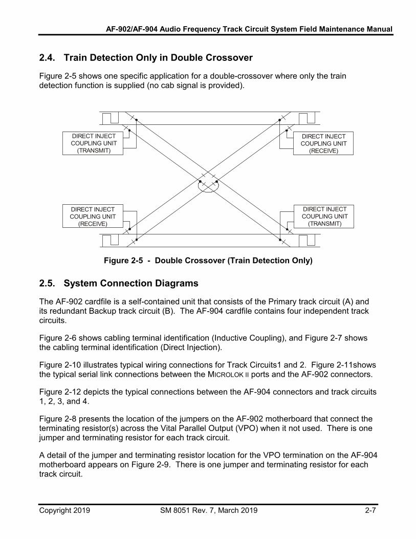
2.4. Train Detection Only in Double Crossover
Figure 2-5 shows one specific application for a double-crossover where only the train detection function is supplied (no cab signal is provided).
DIRECT INJECTCOUPLING UNIT
(TRANSMIT)
DIRECT INJECTCOUPLING UNIT
(TRANSMIT)
DIRECT INJECTCOUPLING UNIT
(RECEIVE)
DIRECT INJECTCOUPLING UNIT
(RECEIVE)
Figure 2-5 - Double Crossover (Train Detection Only)
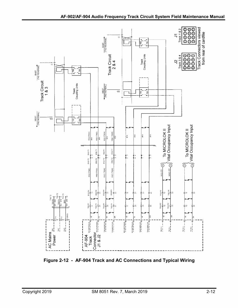
2.5. System Connection Diagrams
The AF-902 cardfile is a self-contained unit that consists of the Primary track circuit (A) and its redundant Backup track circuit (B). The AF-904 cardfile contains four independent track circuits.
Figure 2-6 shows cabling terminal identification (Inductive Coupling), and Figure 2-7 shows the cabling terminal identification (Direct Injection).
Figure 2-10 illustrates typical wiring connections for Track Circuits1 and 2. Figure 2-11shows the typical serial link connections between the MICROLOK II ports and the AF-902 connectors.
Figure 2-12 depicts the typical connections between the AF-904 connectors and track circuits 1, 2, 3, and 4.
Figure 2-8 presents the location of the jumpers on the AF-902 motherboard that connect the terminating resistor(s) across the Vital Parallel Output (VPO) when it not used. There is one jumper and terminating resistor for each track circuit.
A detail of the jumper and terminating resistor location for the VPO termination on the AF-904 motherboard appears on Figure 2-9. There is one jumper and terminating resistor for each track circuit.

AF-902/AF-904 Audio Frequency Track Circuit System Field Maintenance Manual
Copyright 2019 SM 8051 Rev. 7, March 2019 2-8
TB1-1
TB1-2
TB1-3
TB1-4
TB2-1
TB2-2
TB2-3
TB2-4
TRANSMITTER 1
TRANSMITTER 2 TRANSMISSION LOOP 1
TRANSMISSION LOOP 2
Figure 2-6 - Inductive Coupling Unit, Terminal Identification
GND
Figure 2-7 - Direct Injection Coupling Unit, Terminal Identification

AF-902/AF-904 Audio Frequency Track Circuit System Field Maintenance Manual
Copyright 2019 SM 8051 Rev. 7, March 2019 2-9
Figure 2-8 - VPO Jumpers and Terminating Resistors on AF-902 Motherboard (See Figure 5-1 for additional rear views of the cardfile.)
Figure 2-9 - AF-904 VPO Jumper and Terminating Resistors Detail
(See Figure 5-1 for additional rear views of the cardfile.)

AF-902/AF-904 Audio Frequency Track Circuit System Field Maintenance Manual
Copyright 2019 SM 8051 Rev. 7, March 2019 2-10
Figure 2-10 - AF-902 Track and AC Connectors and Typical Wiring

AF-902/AF-904 Audio Frequency Track Circuit System Field Maintenance Manual
Copyright 2019 SM 8051 Rev. 7, March 2019 2-11
Figure 2-11 - AF-902 Typical Serial Link Connections
AF-902/AF-904 Audio Frequency Track Circuit System Field Maintenance Manual
Copyright 2019 SM 8051 Rev. 7, March 2019 2-12
Figure 2-12 - AF-904 Track and AC Connections and Typical Wiring

AF-902/AF-904 Audio Frequency Track Circuit System Field Maintenance Manual
Copyright 2019 SM 8051 Rev. 7, March 2019 3-1
3. Functional Description 3.1. Introduction
The heart of the AF-902/904 track circuit is a Motorola 68HC16 Micro Controller Unit (MCU). This MCU receives vital asynchronous data from the track MICROLOK II, adds local track circuit data, and converts the data into a synchronous protocol. (See Section 1.4 for a description of this data.) The data is then sent to the transit car via the transmitter, transmitter coupler, and bonds. The MCU monitors the transmitted signal, via the assigned receiver coupling unit, to detect the presence of a train in the track circuit and reports non-interlocking track circuit track occupancy back to the Interlocking MICROLOK II, along with system health and local speed reductions, via a vital RS-485 serial data link and/or by a Vital Parallel Output (VPO) line. The VPO from the AF-902/904 system feeds a MICROLOK II vital input.
3.2. Wayside to Train Message Formation
The protocol of the AF-902/904 track communications link is an asynchronous, bit-oriented protocol. This asynchronous protocol dictates that the clocking information (data timing) be embedded in the message. This embedded signal allows proper decoding of the serial data string.
3.2.1. Data Routing
When a signal is received from MICROLOK II, the MCU extracts the data from the MICROLOK II protocol and vitally stores it in Random Access Memory (RAM). The MCU performs vital logic with the MICROLOK II data and other data stored locally in an Electrically Erasable Programmable Read Only Memory (EEPROM). Since EEPROMs do not use a battery to retain their memory when power is removed, they require no maintenance. The only battery requirement is for the event logging operation. This EEPROM is mounted on the motherboard so that when a controller PCB is replaced, no reprogramming is necessary. However, the maintainer will need to run the track circuit calibration procedure to verify settings and calculate new thresholds.
Each of the four controller PCBs in a cardfile has its own EEPROM. The local data used by this logic is the unique 12-bit ID number of a given track circuit, and possibly a speed restriction, which was entered via the switches on the front of the controller PCB. In addition, configuration information for the unit, such as the MICROLOK II slave address, carrier frequency, track circuit threshold voltages, and any other non-volatile information needed to operate the AF-902/904 system, is vitally stored in the EEPROM. If the speed commanded by MICROLOK II is greater than that of the present local speed restriction (if any), the slower of the two is used.
If the restriction speed is greater than that commanded by MICROLOK II (or is non-existent), the speed commands will be sent as requested by MICROLOK II. Once the proper message has been constructed, the MCU converts the data into a synchronous protocol, using an NRZI format. As configured, the AF-902/904 system uses a 200 baud BFSK carrier to both transmit and detect the presence of a train in the track circuit.

AF-902/AF-904 Audio Frequency Track Circuit System Field Maintenance Manual
Copyright 2019 SM 8051 Rev. 7, March 2019 3-2
The digitally formatted message is transmitted to the vehicle using FSK modulation and contains a total of 61 to 72 bits. The FSK modulation process is explained in more detail in Subsection 3.3. 3.2.2. Data Protocol
The messages delivered to the track by the AF-902/904 system consist of 37 bits of data, an 8-bit header/synchronization character, 16 bits of CRC, and 10 bits of zero insertion or additional fill bits to make a total of 71 bits. Refer to Table 3-1. The message is formed by appending the 16 bits of CRC to the data bits, inserting zeros as needed to prevent the uncoded header 0x7E (hexadecimal) from appearing within the message, inserting fill characters to make the message a fixed length, appending the header to the beginning of the message, and encoding the message using NRZI encoding. The following is a summary of the track message formulation:
Speed: 200 bits per second (200 Baud)
Protocol: Synchronous, bit oriented (similar to SDLC)
Header: 0x7E
Data: 37 bits
CRC: CRC-16
Zero-Bit insertion
Rounding bits to make constant size, 71 bit messages
Encoding: NRZI
Modulation: BFSK
Table 3-1 - Typical Message Bit Representation HEADER DATA STUFFED BITS CRC
8 bits 37 bits 0 to 10 bits 16 bits
61 to 71 Bit NRZ1 Encoded Message (Less Rounding Bits)

AF-902/AF-904 Audio Frequency Track Circuit System Field Maintenance Manual
Copyright 2019 SM 8051 Rev. 7, March 2019 3-3
3.2.3. Message Commands, Functions, and Formation
The data stream is used for both train detection and instructional messages. The number of assigned bits and their assigned instructions are shown in Table 3-2.
Table 3-2 - Bit Assignments BITS FUNCTION DEFINITION
13 Track ID - Including Primary/Backup Indication
Allows for separate track circuits
2 Direction Commands the direction of travel
3 Next cab carrier frequency (9.5 kHz to 16.5 kHz)
Identifies the upcoming track circuit cab signaling frequency
7 Distance-to-go to the target speed – Refer to Table 1-3.
Represents the distance to the target speed
4 Line speed – Refer to Table 1-2. Represents the maximum speed permitted by the train within the control line
4 Target speed – Refer to Table 1-2. Represents the desired speed of the train at the end of the control line
1 Berthed Indicates the vehicle's doors are within the bounds of the usable portion of the station platform
2 Couple and uncouple commands Used during the make up of trains
1 Bifurcation Used for bifurcation
These messages are used on adjacent track circuits along the entire length of the identified transit line. In order to isolate these commands between track circuits, eight available carrier frequencies are alternated throughout the transit line. Each AF-902/904 track circuit is assigned one of eight center frequencies. Bits, which are made up of MARKS and SPACES, are identified by the frequency they are assigned. The center frequencies and the corresponding SPACE and MARK frequencies are shown in Table 3-3.
Table 3-3 - Bit Frequency Assignment CENTER FREQUENCY (kHz) SPACE FREQUENCY (kHz) MARK FREQUENCY (kHz)
9.5 9.3 9.7
10.5 10.3 10.7
11.5 11.3 11.7
12.5 12.3 12.7
13.5 13.3 13.7
14.5 14.3 14.7
15.5 15.3 15.7
16.5 16.3 16.7
3.3. FSK Signal Transmission
BFSK is a method of modulating a center frequency which uses two distinct frequencies to convey the information. One, and only one, of these two frequencies is on at a given time.
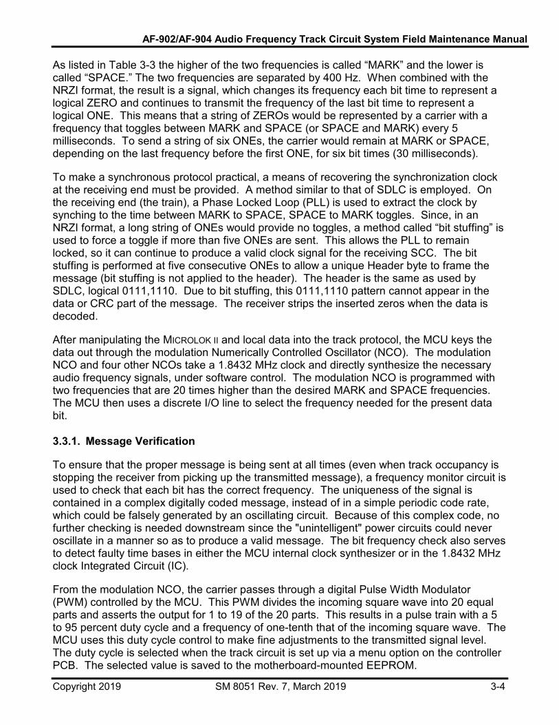
AF-902/AF-904 Audio Frequency Track Circuit System Field Maintenance Manual
Copyright 2019 SM 8051 Rev. 7, March 2019 3-4
As listed in Table 3-3 the higher of the two frequencies is called “MARK” and the lower is called “SPACE.” The two frequencies are separated by 400 Hz. When combined with the NRZI format, the result is a signal, which changes its frequency each bit time to represent a logical ZERO and continues to transmit the frequency of the last bit time to represent a logical ONE. This means that a string of ZEROs would be represented by a carrier with a frequency that toggles between MARK and SPACE (or SPACE and MARK) every 5 milliseconds. To send a string of six ONEs, the carrier would remain at MARK or SPACE, depending on the last frequency before the first ONE, for six bit times (30 milliseconds).
To make a synchronous protocol practical, a means of recovering the synchronization clock at the receiving end must be provided. A method similar to that of SDLC is employed. On the receiving end (the train), a Phase Locked Loop (PLL) is used to extract the clock by synching to the time between MARK to SPACE, SPACE to MARK toggles. Since, in an NRZI format, a long string of ONEs would provide no toggles, a method called “bit stuffing” is used to force a toggle if more than five ONEs are sent. This allows the PLL to remain locked, so it can continue to produce a valid clock signal for the receiving SCC. The bit stuffing is performed at five consecutive ONEs to allow a unique Header byte to frame the message (bit stuffing is not applied to the header). The header is the same as used by SDLC, logical 0111,1110. Due to bit stuffing, this 0111,1110 pattern cannot appear in the data or CRC part of the message. The receiver strips the inserted zeros when the data is decoded.
After manipulating the MICROLOK II and local data into the track protocol, the MCU keys the data out through the modulation Numerically Controlled Oscillator (NCO). The modulation NCO and four other NCOs take a 1.8432 MHz clock and directly synthesize the necessary audio frequency signals, under software control. The modulation NCO is programmed with two frequencies that are 20 times higher than the desired MARK and SPACE frequencies. The MCU then uses a discrete I/O line to select the frequency needed for the present data bit. 3.3.1. Message Verification
To ensure that the proper message is being sent at all times (even when track occupancy is stopping the receiver from picking up the transmitted message), a frequency monitor circuit is used to check that each bit has the correct frequency. The uniqueness of the signal is contained in a complex digitally coded message, instead of in a simple periodic code rate, which could be falsely generated by an oscillating circuit. Because of this complex code, no further checking is needed downstream since the "unintelligent" power circuits could never oscillate in a manner so as to produce a valid message. The bit frequency check also serves to detect faulty time bases in either the MCU internal clock synthesizer or in the 1.8432 MHz clock Integrated Circuit (IC).
From the modulation NCO, the carrier passes through a digital Pulse Width Modulator (PWM) controlled by the MCU. This PWM divides the incoming square wave into 20 equal parts and asserts the output for 1 to 19 of the 20 parts. This results in a pulse train with a 5 to 95 percent duty cycle and a frequency of one-tenth that of the incoming square wave. The MCU uses this duty cycle control to make fine adjustments to the transmitted signal level. The duty cycle is selected when the track circuit is set up via a menu option on the controller PCB. The selected value is saved to the motherboard-mounted EEPROM.

AF-902/AF-904 Audio Frequency Track Circuit System Field Maintenance Manual
Copyright 2019 SM 8051 Rev. 7, March 2019 3-5
The output of the PWM is sent to the auxiliary PCB. On the auxiliary PCB, the carrier is applied to a flip-flop, which divides the frequency in half and provides two opposing phase signals as its output. These signals are applied to a pair of high-current, high-speed Field Effect Transistor (FET) drivers, which boost the signal up to the levels needed to properly drive the four power MOS FETS that form the full bridge power amplifier. The power amplifier gets its power (B+, approximately 44 Vdc) from an onboard rectifier and voltage regulator. A nominal 48 Vac for this supply comes from transformers on the rear of the cardfile. These transformers isolate and step down the 115 Vac ± 10% mains. Two transformers are used for each controller-auxiliary PCB pair (eight per cardfile) to provide good power supply margins.
The output of the power amplifier is fed to the output transformer. This transformer has five secondary taps which provide coarse transmitter level adjustment. The transformer also has an auxiliary winding which is used to monitor the transmitter output level. When transmitting a BFSK message, the signal has almost a constant power output. To ensure that the transmitted level does not increase (due to a failure of the B+ regulator, the PWM, or another component), the signal from the monitor winding of the output transformer is rectified and averaged.
The resulting DC voltage is read by the MCU Analog to Digital Converter and checked to make sure that it falls within a preset value. If the voltage is outside this range, the track circuit Clear Signal is dropped, and the unit transfers control to the standby unit. The range for the power amplifier monitor is set during unit configuration. After the track circuit has been properly adjusted, the installer selects a menu command that measures the voltage coming from the power amplifier monitor, adds a fixed tolerance to it, and vitally stores this range (window) in EEPROM.
The taps of the output transformer secondary are selected using jumpers on the motherboard, so that when a PCB is replaced no adjustments are necessary, except for signal level calibration. On the common side of the secondary is a relay, which can isolate the output from the rest of the system. This form "C" relay is wired to use only the normally open contact set. The relay is controlled by switched power from the CPS so that if the CPS is dropped, the contacts open. The switch allows the contacts to be open when the CPS is up. This is necessary so that the standby unit may run diagnostic tests on its transmitter circuits. The switch is controlled by the MCU via an I/O port, which also drives the seven LED indicators on the auxiliary PCB.
After leaving the cut-out relay and selector taps, the two output leads are routed through a set of direction relays. These are Hengstler safety-style relays with check contacts that indicate the status of the main contacts. If the check contacts are closed, the main contacts are guaranteed to be open. By monitoring the check contacts, the controller PCB ensures that only the correct direction relay is energized. 3.3.2. Equipment Room to Rails
From the relay/equipment room, track leads of up to several kilometers total loop length connect the trackside coupling units to the direction relays. The track leads are twisted pairs with an intrinsic impedance (Zo) of approximately 100 ohms. The coupling units are housed in weather tight enclosures and consist of two totally independent and isolated coupling circuits. Each circuit has its own transformer and capacitor bank. The transformer steps

AF-902/AF-904 Audio Frequency Track Circuit System Field Maintenance Manual
Copyright 2019 SM 8051 Rev. 7, March 2019 3-6
down the high voltage on the leads from the relay room to a low voltage suitable for driving the single turn track loop. The capacitors are jumper-selected to tune the track loop.
This tuning raises the reactance of the track loop to the selected carrier frequency. This raises transmitter efficiency since smaller currents are required to flow in the long track leads. Likewise, when a track loop has been selected to be a receiver, the low voltage from the track loop is stepped up to drive the leads back to the relay room. The tuning of the track loop provides a small increase in received signal strength. Due to the differences in transmitter and receiver impedance, the coupling unit is adjusted, to provide some benefit to both transmitter and receiver. The tuning is necessarily very broad and does not result in any appreciable frequency selectivity between the jointless track circuits.
The AF-902/904 system does not use a conventional impedance bond. Instead, a few meters of 350 or 500 MCM cable are connected between the two rails in an “S” shape, with an end of the "S" bonded to each rail. Single turn track loops are mounted inside of the upper and lower parts of the "S." Currents circulating in the transmitting track loop are induced into the “S” and onto the track. Likewise, currents from the track circulate in the “S” and are induced into the receiving track loop. This type of bond has a strong directionality, with the ratio of the length to the width of the “S" determining the “directivity” (like the front-to-back ratio on an RF directional antenna). The track loop that transmits or receives is determined by the direction relays on the rear of the cardfile.
3.4. Train Detection
Each AF-902/904 system vitally monitors the status of a single track circuit. The FM audio frequency carrier that is transmitted at one end of the track circuit and received at the other end, is used not only for the digital cab signal data, but also for train detection. The carrier level and a part of the digital message are monitored by the receiver to determine track occupancy.
When a train shunts the rails of the monitored track circuit, the signal is blocked. This condition is recognized by the receiving AF-902/904 circuits as a drop below a preset signal threshold and is reported to the associated interlocking MICROLOK II system as an occupied circuit. Communications of track occupancy can be sent to the vital MICROLOK II by either or both an RS-485 vital serial link or a vital parallel output. While the shunting train bridges adjacent track circuits, both are reported as occupied. When the train clears a track circuit, the received signal threshold is restored and the AF-902/904 system responds accordingly.
From the selected receive cable, the returning signal passes through a disconnect relay before being applied to the receiver transformer. This relay is also wired to operate in a normally open manner and is closed only when the CPS for the unit is up and the MCU has switched on the relay. The receiver disconnect relay is controlled by the same switched CPS power as the transmitter disconnect relay. A single relay could not be used due to the safety requirement of preventing a direct short between the transmitter and receiver.
The receiver transformer has five taps. These taps allow the AF-902/904 equipment to be adjusted for different operating conditions, such as track lead length, direct injection vs. bond injection, and loop driving without a bond. The selected tap is clamped by a TransZorb™ to protect the receiver circuits.

AF-902/AF-904 Audio Frequency Track Circuit System Field Maintenance Manual
Copyright 2019 SM 8051 Rev. 7, March 2019 3-7
3.5. Monitoring and Fail-Over
Since the AF-902/904 track circuit unit is an interface between the MICROLOK II system and the trackside equipment, it is necessary to monitor the vital communications data and hardware performance. This requires that the communications between the MICROLOK II unit and the AF-902/904 unit are functioning properly. Also, internal data signal processing within the AF-902/904 system must be functioning properly. This requires that the data or signal levels to and from the rails are accurate and available to the cab.
The left controller/auxiliary PCB pair of each track circuit is called the Primary, and the right pair is called the Backup. These terms refer to the physical placement of the PCBs. The unit that is operating the track circuit is called the On-Line unit and the other unit is called the Standby unit. This logical distinction is needed because a failed or powered-off Primary unit could be replaced and/or powered up without it becoming the On-Line unit. The Primary unit remains the Standby unit until either the power is cycled to both units or the Backup unit fails. 3.5.1. MICROLOK II Monitoring
The MICROLOK II acting as the protocol master monitors various aspects of the data communications link between the AF-902/904 unit and itself. AF-902/904 faults pertaining to incorrect message contents, message length, or response time will result in a system error and cause the message to be discarded. Additional fault details are described in Section 7. 3.5.2. AF-902/904 Monitoring
The AF-902/904 unit must monitor the communications link between the MICROLOK II and itself, internal reliability, and the transmit and receive signals to the rails.
3.5.2.1. MICROLOK II RS-485 Communications Link
The following is a set of possible fault conditions that could be detected by an AF-902/904 system acting as a protocol slave unit. The faults pertain to master polling messages sent by the MICROLOK II to the AF-902/904 system.
Timeouts If an AF-902/904 system does not receive a poll from the MICROLOK II in 3 seconds, it will declare the link to be down.
CRC Mismatch If a CRC does not match for a message received from MICROLOK II, the AF-902/904 system will discard the invalid message.
Incorrect Length If a response message from the MICROLOK II is either too long or too short because of any data bytes or CRC mismatch, the incomplete message will be discarded.

AF-902/AF-904 Audio Frequency Track Circuit System Field Maintenance Manual
Copyright 2019 SM 8051 Rev. 7, March 2019 3-8
No Acknowledgment If an acknowledgment indication is not received by the AF-902/904 system from MICROLOK II, the AF-902/904 system will declare the link to be down.
3.5.2.2. AF-902/904 Cardfile Unit
Each AF-902/904 subsystem must pass its own continuous internal diagnostics. In the event of a failed vital diagnostic, the controlling microprocessor stops transmitting a 500 Hz vital signal to the subsystem CPS on the auxiliary PCB. When this signal is removed, the CPS shuts down, preventing cab signal data transmission and indications of a clear track. In AF-902 systems, if the Primary track circuit controller fails, the Backup track circuit automatically switches into operation. This automatic fail-over is transparent to the operation of the system.
Transmit Data Monitoring
To ensure that the proper message is being sent at all times (even when track occupancy is stopping the receiver from picking up the transmitted message), a frequency monitor circuit is used to check that each bit has the correct frequency. Because of this complex code, no further checking is needed downstream, since the “unintelligent” power circuits could never oscillate in a manner so as to produce a valid message. The frequency check also serves to detect faulty time bases in either the MCU internal clock synthesizer or in the 1.8432MHz clock IC.
Receiver Systems Monitoring
The AF-902/904 unit is constantly transmitting to the track circuit for occupancy or broken rail indications. These transmissions are also used to verify and monitor the accuracy and integrity of the data and signal levels.
To ensure that the receiver systems are operating correctly, a test signal is added to the track signals just before the input BPF. This signal must fall within a fixed range when monitored on the designated test channel. All three receivers are checked by reprogramming their NCOs at the end of each message, per Table 3-4.
Table 3-4 - Receiver NCO Programming
RECEIVER CHANNEL
FUNCTION AT MSG1
FUNCTION AT MSG2
FUNCTION AT MSG3
FUNCTION AT MSG4
FUNCTION AT MSG5
FUNCTION AT MSG6
1 Mark Space Test Space Mark Test
2 Space Test Mark Mark Test Space
3 Test Mark Space Test Space Mark
The source of the test signal is a NCO on the auxiliary PCB. This NCO is set to a frequency other than that of the MARK or SPACE used in the track circuit. The NCO drives an analog switch that chops a DC voltage from the TEST Digital to Analog Converter (TEST DAC).
AF-902/AF-904 Audio Frequency Track Circuit System Field Maintenance Manual
Copyright 2019 SM 8051 Rev. 7, March 2019 3-9
Once the MCU has determined that the track circuit is clear, unoccupied and unbroken, it asserts the vital output on the MICROLOK II. The vitality of the output is accomplished by switching off the output transistor and measuring the output voltage. If more than a predetermined voltage (to account for leakage currents) is preset, the MCU shuts down the CPS. With the CPS dropped, there is no power source for the output circuit.
A non-vital, normally open disconnect relay allows the vital output to be tested on the Standby unit. Power for the coil of this relay is provided by the CPS, so that a coil-to-contact short cannot assert the output when the CPS is dropped. As a check that this non-vital relay is closed when the unit is On-Line, an independent non-vital circuit checks that when the vital output of the On-Line unit is on, voltage is present on the line to MICROLOK II. A diode is used to isolate the relay from the wire to the MICROLOK II so that if the relay should fail to open, it will not prevent the Backup unit from driving the line. If both the relay and the diode fail, the system is still in a safe state, since a low signal on this line indicates track occupancy. 3.5.3. Fail-Over (AF-902 System Only)
The CPS is a Class I vital circuit that only produces power when a 500 Hz square wave is provided to it from the MCU. The MCU runs many complex diagnostic tasks on itself and on the rest of the AF-902 unit. These tests range from testing of CPU memory and logic processing to full closed-loop tests of the vital output, transmitter and receiver circuits. If any of these diagnostics fail, the MCU stops toggling the 500 Hz line and the CPS drops out. The CPS is the sole power source for the vital output and the modulation oscillator clock source. When the CPS is dropped, the unit cannot transmit or indicate a clear track, no matter what the failure.
The CPS also has a non-vital output which provides power for the disconnect relay coils, except for the relay that disconnects the vital output. The vital output relay gets its coil power from the vital supply, so that a coil-to-contact short cannot energize the circuit when the CPS is down. If the CPS is down, all coils lose power and the AF-902 unit drops Off-Line. The CPS interlock on the disconnect relays makes it very unlikely that a failed unit could keep its Standby unit from restoring proper operation to the track circuit. However, even if a disconnect relay were to become welded in the closed state, the design of the circuits is such that no safety problems would arise since the CPS vitally removes power from the vital Class II circuits.
AF-902 units have been configured to provide full redundancy for each individual track circuit. Each 19-inch (48.26 cm) cardfile can house the electronics for two track circuits, with each track circuit having two controller/auxiliary PCB pairs and a common power supply PCB. The power supply PCB has two independent supply systems, with switches to cut the AC mains for each. Each supply provides +15 Vdc, +5 Vdc, –15 Vdc and a nominal 48 Vac. The two-track-circuit cardfile is wired such that the two Primary units are powered by one 115 Vac ±10%, and the two Backup units are powered by a second independent 115 Vac ±10% main.
When the AF-902 units are simultaneously powered up and operating properly, the Primary pair (left) is the On-Line unit and the Backup pair (right) is the Standby unit. The hardwiring on the motherboard determines which AF-902 unit is the Primary unit, and which AF-902 unit is the Backup unit. The Standby unit is up and running the same software as the Primary unit, except that it is isolated by the disconnect relays. The two units communicate to each

AF-902/AF-904 Audio Frequency Track Circuit System Field Maintenance Manual
Copyright 2019 SM 8051 Rev. 7, March 2019 3-10
other through a dedicated serial link. Two DC lines cross-link the Primary MCU to the Backup CPS, and the Backup MCU to the Primary CPS, to provide a second check on the health of each unit.
A Standby unit will not try to go On-Line unless it is not receiving communications from the old On-Line unit and it has detected that the old On-Line unit CPS is dropped. If this happens, the Standby unit will become the On-Line unit, the old On-Line unit will be Off-Line, and the new On-Line unit will inform MICROLOK II that the track circuit is not healthy. The health bit in the MICROLOK II message is only set when both Primary and Backup units are working properly. If the On-Line unit stops receiving communications from the Standby unit or detects that the Standby unit CPS is dropped, it informs MICROLOK II that the track circuit is not healthy. A maintainer should be dispatched to correct the problem whenever the health bit is not set.

AF-902/AF-904 Audio Frequency Track Circuit System Field Maintenance Manual
Copyright 2019 SM 8051 Rev. 7, March 2019 4-1
4. Front Panel Menu Operation 4.1. Introduction
The front panel menu system of the AF-902/904 unit is used to modify and display vital and non-vital system parameters and to execute system functions. Any operator can access any menu function, except for the configuration functions, which can be accessed only by authorized operators. The operation of the switches is consistent across all functions.
4.2. Front Panel Displays, Controls, and Operation
The menu control system consists of two, four-character alphanumeric scrolling displays. The system also has four up-down SPDT toggle switches used to enter and examine data used in the setup and operation of the track circuit. Five LEDs provide additional information. In addition, a front panel PC-compatible serial port and a background mode debugging port are available. The serial port can be made available to the end user, but the background port is for factory use only. Figure 4-1 shows the switches and displays as well as the corresponding names and identification.
4.2.1. Displays
The display section is composed of two four-character alphanumeric displays and five LEDs. The upper display is red and the lower display is green.
The upper display is wired to prevent an address decode failure. This wiring method prevents both displays from displaying the same data.
There are four system monitoring LEDs on the controller PCB controlled by three different sources. These LEDs are mapped as shown in Table 4-1.
Table 4-1 - Controller PCB LED Mapping
CONTROLLER LED SIGNIFICANCE WHEN
ON SIGNIFICANCE WHEN
OFF SIGNIFICANCE WHEN
FLASHING
W WEST/NORTH/ NORMAL relay PICKED
WEST/NORTH/ NORMAL relay DROPPED
WEST/NORTH/ NORMAL relay PICKED
TRACK SHUNTED
E EAST/SOUTH/ REVERSE relay PICKED
EAST/SOUTH/ REVERSE relay
DROPPED
EAST/SOUTH/ REVERSE relay PICKED
TRACK SHUNTED
1 FAILOVER link GOOD FAILOVER link BAD N/A
2 CONFIGURATION MODE ON-LINE or STANDBY MODE
UNCONFIGURED or ERROR-TRAP mode

AF-902/AF-904 Audio Frequency Track Circuit System Field Maintenance Manual
Copyright 2019 SM 8051 Rev. 7, March 2019 4-2
UP
DOWN
ADJMODE
AUX 1
PRESS TORESET
IN RESETWHEN LIT
ESCAPE
STATUSLEDS 2
1
DIR.W
E
DEBUGPORT
TRK CKTCTRLR
N123603-01
DIAGPORT
ALPHANUMERICLED DISPLAYS
MOTOROLABACKGROUNDDEBUG PORT
(FACTORY USE ONLY)
CONFIGURATION SETUPSWITCHES
MOMENTARY CONTACTSWITCHES
(SPRING RETURN TO CENTER)
SYSTEM MONITORLEDS
SYSTEM RESETPUSHBUTTON
9-PIN PORTFOR
PORTABLE PC(RE-232DTE)
EN TER AUX 2
Figure 4-1 - AF-902/AF-904 Controller PCB Front Panel

AF-902/AF-904 Audio Frequency Track Circuit System Field Maintenance Manual
Copyright 2019 SM 8051 Rev. 7, March 2019 4-3
4.2.2. Controls
Each menu of the AF-902/904 system uses the control switches for the following purposes: Mode Up Scrolls forward through selections or display parameters.
Mode Down Scrolls backward through selections or display parameters.
Adjust Up Increases the current parameter. Where appropriate, when the maximum value is reached, the parameter rolls over to the minimum value. In the Display submenus, the Adjust Up switch is used to modify the display code.
Adjust Down Decreases the current parameter. Where appropriate, when the minimum value is reached, the parameter rolls over to the maximum value. In the display submenus, the Adjust Down switch is used to modify the display code.
Enter Enters a submenu or confirms a parameter value.
Escape Backs out of a submenu or cancels an operation.
Aux. 1 Enters the blocking speed menu. This switch has no effect on the restricted access menus.
Aux. 2 Enters the blocking speed menu. This switch has no effect on the restricted access menus.
4.2.3. Front Panel Operation
On-site setup of operating parameters is accomplished using the front panel controls and displays. Parameter adjustments available on the AF-902/904 system include: • Unique 12 bit track circuit ID (number between 1 and 4,095) • Slave address for MICROLOK II serial link • Transmit carrier frequency and signal strength • Train detection threshold voltage • Blocking Speed restriction (when required) • New password
All of the parameter setup functions, except Blocking Speed, are password-protected.
Controller PCB displays and controls also permit real-time examination of data received from the track MICROLOK II system and the monitored track circuit, including: • Current line and target speeds

AF-902/AF-904 Audio Frequency Track Circuit System Field Maintenance Manual
Copyright 2019 SM 8051 Rev. 7, March 2019 4-4
• Target distance • State of berthing data bit • States of east/west direction-of-travel data bits • States of couple/uncouple data bits • Next transmit frequency • Current track circuit ID number • Bifurcation bit
Detailed monitoring and diagnostics of the AF-902/904 logic and memory can be performed using a portable PC plugged into a 9-pin serial port on the front of the controller PCB front panel. The portable PC may use any standard terminal emulation software.
4.3. Menu Hierarchy
The menus are arranged in a hierarchical manner. The Main menu is used to select four top-level submenus, from which it is possible to display and modify specific system parameters. Figure 4-2 at the end of this section illustrates the menu hierarchy. The remainder of this section describes each menu and submenu function. The hierarchy of the text in this section matches the hierarchy of the diagram.
The front panel menus are divided into two categories, restricted and unrestricted based on access privileges. In addition to access restrictions, there are several other properties that characterize the operation of the AF-902/904 interface, including password entry, cardfile configuration, key repeat rate, key repeat delay, and time-out.
4.3.1. Menu Access
4.3.1.1. Restricted Access Menus
The configuration submenu is a restricted access menu that can be used only by an authorized operator to configure critical system parameters (restricted access parameters). Erroneous entry of restricted access parameters may cause the system to behave in an unsafe manner. It is therefore necessary that these parameters be configured only by qualified personnel. Restricted access parameters can be modified only after a password is entered, and the modified parameters can be made operational only after the password is reentered and all changes are confirmed. When an operator enters the configuration submenu, both the On-Line unit and the Standby unit suspend normal operations. The On-Line unit suspends track transmission and MICROLOK II response, and all outputs on both units are put into a safe state. Normal operation resumes only after the system is reset.
4.3.1.2. Unrestricted Access Menus
Unrestricted access menus permit an operator to perform functions that cannot result in unsafe system operation. All of the system submenus, except the configuration submenu, are considered unrestricted access menus.

AF-902/AF-904 Audio Frequency Track Circuit System Field Maintenance Manual
Copyright 2019 SM 8051 Rev. 7, March 2019 4-5
4.3.2. Password Protection
To enter the configuration submenu and save modified parameters, a password is required. Entering the password is similar to modifying the track ID number and is described in Section 4.3.10.1. The default password can be modified via the password modification submenu.
4.3.3. Cardfile Configuration
When a restricted access parameter is changed, it must be changed to the same value in both the Primary and Backup units in an AF-902 system. The only exception is the Blocking Speed setting. This value is communicated between the Primary and Backup unit, with the most recently set value communicated to both units. If the Primary and Backup have different values at startup, the most restrictive (lowest) speed will be used by both units. Since the AF-904 does not have a Backup unit, this function does not apply.
4.3.4. Key Repeat Delay
If a key is held in the same position for longer than the key repeat delay, it will begin to repeat at the key repeat rate. The key repeat delay is set to 2/5 second. The key repeat rate is set to 5 per second.
4.3.5. Time-out
To prevent unauthorized operators from using the configuration menu, the system will automatically time-out if this menu is active and 20 minutes have passed without the operator pressing a switch. The system will automatically reset, and any changes that may have been made to the system parameters will be lost.
4.3.6. Main Menu
This menu is used to select a top level submenu function. The following top-level submenus are available from the Main menu: Blocking Speed, Display, Events, and Configuration. These submenu functions are described in the following sections. Since the Main menu is at the top of the hierarchy, the Escape front-panel control switch position has no effect from this menu.
4.3.7. Blocking Speed Menu
This menu is used to select the Blocking Speed Adjust submenu from which it is possible to set or modify a blocking speed. This menu option can also be entered immediately from any unrestricted access menu by pressing the Aux Up/Aux Dn switch.
The Blocking Speed Adjust submenu is used to set a blocking speed. The Adj Up/Adj Dn switch modifies the current value (the value displayed on the lower display), and the Enter switch is used to enter the value. The operator must then confirm the value by pressing the Enter switch again, or reject the value by pressing the Escape switch to exit.

AF-902/AF-904 Audio Frequency Track Circuit System Field Maintenance Manual
Copyright 2019 SM 8051 Rev. 7, March 2019 4-6
4.3.8. Display Menu
This option contains submenus that are used to display current system information. The following submenus are available from the Display menu: MICROLOK II Message, Track Message, and System Parameters. The Escape switch will move out of any Display submenu.
4.3.8.1. MICROLOK II Message
This menu contains submenus that are used to display the current message to MICROLOK II from the AF-902/904 system and the current message from MICROLOK II to the AF-902/904 system.
4.3.8.2. Track Message
This menu contains submenus that are used to display the following information: • Current message being delivered to the track by the AF-902/904 system (Transmit
menu). • Level of the received signal as a percent of the threshold (Receive menu, Signal Strength
(STR) submenu).
4.3.8.3. System Parameters
This menu is used to display the current system parameters. The following parameters are displayed: block speed, MICROLOK II address, track ID, Primary/ Backup, frequency, configured transmit power West, and configured transmit power East.
4.3.9. Events Menu
This menu is used to select a submenu from which it is possible to display events and manage the event logging system. The following submenus are available from the Events menu: View Events, Clear Events, and Dump Events.
4.3.9.1. View Events Menu
The View Events menu allows the maintainer to view in reverse order the event numbers logged by the AF-902/AF-904 system.
4.3.9.2. Clear Events Menu
The Clear Events menu will erase all recorded event numbers from the AF-902/AF-904 memory.
4.3.9.3. Dump Events Menu
Selecting the Dump Events menu will cause the event data to be transmitted to a serial data communications terminal connected to the front panel DIAG PORT.
AF-902/AF-904 Audio Frequency Track Circuit System Field Maintenance Manual
Copyright 2019 SM 8051 Rev. 7, March 2019 4-7
4.3.10. Configuration Menu
This menu contains submenus that modify system parameters. The Password Entry submenu allows the user to enter the password. The Restricted submenu option contains other submenus that allow the user to modify critical system data.
4.3.10.1. Password Entry
This submenu option is used to enter and validate the restricted access password. The four-character password is entered one character at a time. The active character flashes, while inactive characters are displayed constantly. Initially, “AAAA” is displayed and the leftmost character is active. The Adj Up/Adj Dn switches are used to advance the active character through the elements of the password character set. The Enter switch selects the current value of the active character and activates the next character.
4.3.10.2. Restricted Menu Option
This submenu option is used to select a restricted access submenu. If the proper password has not been entered using the Password Entry menu, the submenus of the Restricted menu are not available. To enter the restricted access menus, the AF-902/AF-904 will automatically go through a reset cycle. If there is a Backup unit in an AF-902 system it must be turned off prior to entering the Restricted menu. The following sections describe the submenus available from the Restricted menu. Exiting from the Restricted menu will cause the unit to reset.
After the reset occurs, three menu selections are available: Setup, Utility, and Accept.
Setup Menu
Selecting this menu, by pressing the Enter switch, will make four submenu selections available to the Maintainer: Tune, MICROLOK II, ID, and Calibration.
a. Tune Menu
The Tune submenu is used to configure the AF-902/904 system for train detection and cab signaling. The Tune menu contains several sequential submenus to be used in conjunction with the track circuit setup and tuning procedure. Because of the sequential nature of the tuning procedure, a menu item may have both a function and a submenu.
Via the Frequency Adjust menus, the user can change the carrier frequency in either the West to East or East to West signal transmission direction. The Adj Up/Adj Dn switches are used to modify the value that is displayed, and the Enter switch moves to the Power Output menu.
The Power Output menus provide an adjustment of transmitter power. The Adj Up/Adj Dn switches are used to modify the value that is displayed, and the Enter switch moves to the submenu.

AF-902/AF-904 Audio Frequency Track Circuit System Field Maintenance Manual
Copyright 2019 SM 8051 Rev. 7, March 2019 4-8
b. MICROLOK II Menu
This menu permits the user to select the MICROLOK II Address Adjust submenu, which can be used to change the MICROLOK II station address.
c. ID Menu
With the ID menu option, the user can enter the track identification number (1 to 4095).
d. Calibration Menu
Via the Calibration menu, the user sets the operating parameters of the AF-902/AF-904 system. The function and use of each submenu is described in Section 4 of this manual.
Utility Menu
This menu can be used to access two submenus: New Password and Clear Configuration (operating parameters).
a. New Password Menu
The New Password function allows the user to change the default password. The password is modified using the Adj Up/Adj Down switches and pressing the Enter switch sequentially confirms each character. The Escape switch backs up by one character or cancels the operation if the first character is displayed. After the password has been entered, the user is asked to confirm the value. A password that is modified and then confirmed immediately becomes the system password. The default password can only be restored by physically replacing the EEPROM on the motherboard.
b. Clear Configuration Menu
This function allows the maintainer to erase all configuration parameters of the AF-902/904 system. Attempting to operate the system after this selection is made will cause the system to enter the unconfigured mode.
Accept Menu
This menu is used to confirm the changes that have been made to the restricted access system parameters. The Accept menu is a group of menus that sequentially prompt the maintainer to confirm the modifications that have been made to the system parameters. The parameter identifier is displayed first, followed by the new value shown on both the top and bottom displays.
The operator must press either the Enter switch to confirm that both displays indicate the correct parameter or the Escape switch to abort the modification. After each modified parameter has been confirmed, a Password Entry menu is activated. This menu is similar to

AF-902/AF-904 Audio Frequency Track Circuit System Field Maintenance Manual
Copyright 2019 SM 8051 Rev. 7, March 2019 4-9
the menu described above. If the correct password is entered, the system parameters are written to the system EEPROM and will be used for all subsequent operations.

AF-902/AF-904 Audio Frequency Track Circuit System Field Maintenance Manual
Copyright 2019 SM 8051 Rev. 7, March 2019 4-10

AF-902/AF-904 Audio Frequency Track Circuit System Field Maintenance Manual
Copyright 2019 SM 8051 Rev. 7, March 2019 4-11
MAINMENU
BKSPMENU
DISPMENU
EVNTMENU
Cancel
bksp.35
CON-FIRM
.35
.35
DeniedDone
Denied
SYSMENU
MLOKMENU
TRKMENU
bksp35Mlok
1TkID2199
PrimYesFreq13.5PwrW10%PwrE10%
E
W1
0Nxfq15.5
TD9000
LS65
TS65Brth
0Cpl0
Denied
Ucpl0Bifr0
TXMENU
RXMENU
BkspsetHlthokTrkok
E
W1
0Nxfq15.5
TD9000
LS65
TS65Brth
0Cpl0Ucpl
0Bifr0
RXMENU
TXMENU
Strxxx%
VIEWEVNT
CLREVNT
DUMPEVNT
#170033
#160059
#10033
Done Done
DISPMENU
CNFGMENU
pswdAAAA
PSWDMENU
WAIT
Cancel
Cancel
Invalid SystemReset
SystemReset
RSTRMENU
SETUP
ACPTMENU
UTILMENU
NEWPSWD
pswdAAAA
CON-FIRM
CLRCNFG
Sure?
11
TUNEMENU
CALIBRAT
freq13.5
Cancel
IDMENU
TkID2199
Cancel
MLOKMENU
addr1
Cancel
DIRW->E
freq10.0
Cancel
DIRE->W
freq10.0
Cancel
Invalid
WAIT
Deniedpwr10%
Denied
WAIT
WAIT
Deniedpwr10%
Denied
WAIT
Cancel
Cancel
MlokAddr
21992199
TkID
AAAAAAAA
NewPswd
PrimPrim
PrimBkup
13.513.5
Freq
10%10%
PoutW->E
10%10%
PoutE->W
pswdAAAA
WAIT
DoneDenied
Invalid
Sure?
DIRW->E
WAIT
pwr10%
DIRE->W
WAIT
pwr10%
Denied
Denied
Levl95%
Vari2% Denied
Shnt70%
DIRW->E
WAIT
Levl98%
Vari2%
Shnt70%
WAIT
AC-CEPT Denied
Denied
Denied
Crsp0
Invalid
WAIT
(To Accept
Menu)
A
B
AF-902 / AF-904 Menu System Navigation
Move from menu "A" to menu "B" bydepressing the "Enter" switch
A
B
Move from menu "B" to menu "A" bydepressing the "Escape" switch
A B Move "left/right" with the "Mode - Up"and "Mode - Down" switches
A dashed line indicates the move will happenautomatically when the task is completed
Note: When a menu allows a value to be adjusted, press the "ADJ - Up" toincrease the value and "ADJ - Down" to decrease the value.
A0
B0
Move between stacked information menus withthe "Mode - UP" and "Mode - Down" switches
Figure 4-2 - Menu System Hierarchy


AF-902/AF-904 Audio Frequency Track Circuit System Field Maintenance Manual
Copyright 2019 SM 8051 Rev. 7, March 2019 5-1
5. Installation and Adjustment 5.1. Introduction
Track circuit installation and adjustment depend on the assigned block frequency and track coupling methods.
Installation procedures should be in accordance with those recommended by the equipment manufacturers for any equipment that interfaces to the AF-902/904 unit. Each installation requires cable interfacing for the assigned system. Refer to the specific site plans for detailed installation and track coupling requirements, such as track circuit lengths, frequency assignments, track circuit identifications, and wiring sheets.
5.2. Recommended Test Equipment
The following equipment is recommended for testing the AF-902/904 unit: • Spectrum Analyzer: Tektronix TDS 3012B Oscilloscope or Hewlett-Packard HP3560A
Dynamic Signal Analyzer. (Refer to Section 9 for Tektronix TDS 3012B setup instructions.)
• Current Probe: Tektronix A621 AC Current Probe or Fluke 80i 1000s Current Transformer.
• AAR Style 1/2 in. hex socket wrench used for loosening and tightening AAR standard terminal posts.
• Red tags for identifying failed PCBs. • Two VOLTREX 855-B Insulated Tip Plugs for PCB Front Panel test probes. • Hand-held radios with 2-mile (3.2 km) range minimum. • Track Shunt 0.25 ohms total resistance. The track shunt resistor itself is 0.20 ohms and
the leads to the rails are 0.05 ohms.
5.3. Serial Link Configuration
Typically, a MICROLOK II communicates to multiple AF-902/904 units through a multi-drop RS-485 link. Terminating resistors must be connected at the physical end of the link, i.e., at the AF unit farthest from the MICROLOK II. Connecting the terminating resistors at the end unit is accomplished by closing the four SW1 rocker switches on the back of the AF motherboard (See Figure 5-1). Otherwise, the four SW1 rocker switches should remain open.

AF-902/AF-904 Audio Frequency Track Circuit System Field Maintenance Manual
Copyright 2019 SM 8051 Rev. 7, March 2019 5-2
5.4. Vital Parallel Output Terminations
A provision for terminating an unused vital parallel output is available (See Figure 2-8 and Figure 2-9). When the VPO is unused, place the jumper for that track circuit in position 2-3 to terminate the output.
5.5. Initial Power Checks
Because of the large dynamic range imposed by the needs of different track circuits, the AF-902/904 Control cardfile incorporates five adjustable transformer taps for both track receiver circuits. These allow for variables such as different track lead lengths. Adjustments are made via jumpers on the cardfile backplane so that a system reset is not required with change-out of the track interface circuitry.
Output power is varied by two means: • Coarse: Output Transformer Taps (1 through 5) on back of the AF-902/904 motherboard.
Taps act to double output amplitude with each increased setting. (TXA= Primary; TXB = Backup)
• Fine: Pulse width, the "ON" duty cycle percentage of a Full Cycle. Set from the Display menu on the front panel and the PWR submenu option.
5.6. Tuning Procedure
Installation of the track circuit requires a setup procedure. This procedure comprises two alignment procedures. The first of these procedures is called the tuning procedure. The second is the calibration procedure.
Tuning of the two associated coupling units to the desired track circuit frequencies is performed first. These frequencies range from 9.5 kHz to 16.5 kHz in l kHz increments.
Specific steps and details of the tuning procedure are given in Table 5-3.
5.7. Calibration Procedure
The second of the setup alignment procedures is the calibration procedure. This procedure must be performed after the tuning procedure since it is affected by the resulting tuning signal levels.
Specific steps and details of the calibration procedure are given in Table 5-5.
Tuning is done at the coupling units mounted near the track bond. The coupling unit contains two identical circuits, which are separated by a dashed line down the middle of the PCB. The operator should take care in determining which of these circuits is to be tuned before proceeding.

AF-902/AF-904 Audio Frequency Track Circuit System Field Maintenance Manual
Copyright 2019 SM 8051 Rev. 7, March 2019 5-3
NOTE The following procedures distinguish the two identical circuits by using standard text for the left unit circuit and {BRACKETS} for the {RIGHT UNIT} circuits.
Tuning affects both the transmitted and received signal levels, making it MANDATORY that the tuning procedure be performed first as part of the setup routine.
For preventive maintenance purposes, since the system is operational and tuning has been completed at some earlier date, calibration alone can be performed as the sensitivity check. However, if calibration is marginal, it may be necessary to perform both the tuning procedure and calibration procedures.
5.7.1. Testing Codes and Abbreviations
5.7.1.1. Controller Board Display Abbreviation Codes
Basic character and case assignments used for performing the test procedures are as follows:
[AAAA] Upper Menu or Command
[Aaaa] Label Parameter
[BKSP] Block Speed
[MLOK] MICROLOK II
[TUNE] Tuning Procedure
[Levl] Input Rec Level
[CALI] [BRAT] Calibration Procedure
[Shnt] Shunted with respect to Level
[MLOK] MICROLOK II Address Set Menu
[aaaa] Changeable Parameter
[ID] Track Circuit ID Set Menu
[tkid] Track Circuit ID Parameter
[PSWD] Password
[pwr] Output Pulsewidth
[RSTR] Restricted Menu

AF-902/AF-904 Audio Frequency Track Circuit System Field Maintenance Manual
Copyright 2019 SM 8051 Rev. 7, March 2019 5-4
5.7.2. Test Equipment and Tools
The equipment and tools required for the tuning and calibration procedures are listed below. The test engineer should select the appropriate tools for the required test procedure. • Spectrum Analyzer: Tektronix TDS 3012B Oscilloscope or Hewlett-Packard HP3560A
Dynamic Signal Analyzer. (See Section 9 for Tektronix TDS 3012B setup instructions.) • Current Probe: Tektronix A621 AC Current Probe or Fluke 80i 1000s Current Transformer • AAR Style 1/2 in. hex socket wrench used for loosening/tightening AAR standard terminal
posts • Red tags for identifying failed PCBs • Two VOLTREX 855-B Insulated Tip Plugs for PCB Front Panel test probes • Handheld radios with 2-mile (3.2 km) range minimum • Track Shunt 0.25 ohms total resistance. The track shunt resistor itself is 0.20 ohms and
the leads to the rails are 0.05 ohms.
5.7.3. Transmit Power Adjustments
During the test procedure, it may become necessary to adjust the output power in order to meet specifications. Output power can be varied by two means:
Coarse: As Figure 5-1 shows, the Output Transformer Taps (1 through 5) on back of the AF-904/904 motherboard are selected by means of jumper wires connected between the numbered taps and Signal Common points (labeled COM for AF-902, and R1 through R4 and T1 through T4 for AF-902). Taps act to double the output amplitude with each increased setting (TXA=Primary; TXB=Backup).
Fine: Pulse width, the ON duty cycle percentage of Full Cycle in 5% increments from 25 to 95%. This is set from the front panel PWR submenu option. It is done during the calibration procedure, and can be done only after the operator has traversed the Configuration menu with the correct password. There is a separate pulse width setting for each direction of track circuit transmission. After these are SET and ACCEPTED, they are stored in EEPROM.

AF-902/AF-904 Audio Frequency Track Circuit System Field Maintenance Manual
Copyright 2019 SM 8051 Rev. 7, March 2019 5-5
TRACK 4
RX4 5
4
3
2
1
R4
5
4
3
2
1
T4
TX4
TRACK 3
RX3 5
4
3
2
1
R3
5
4
3
2
1
T3
TX3
TRACK 2
RX2 5
4
3
2
1
R2
5
4
3
2
1
T2TX
2
TRACK 1
RX1 5
4
3
2
1
R1
5
4
3
2
1
T1
TX1
SW1
RXB 5
4
3
2
1
5
4
3
2
1
COM
RXA
TXB 5
4
3
2
1
5
4
3
2
1
TXA
TXB 5
4
3
2
1
5
4
3
2
1
TXA
RXB 5
4
3
2
1
5
4
3
2
1
RXA
SW1
TRK2COM COM COM
AF-904 Upper Cardfile Rear View
AF-902 Upper Cardfile Rear View
TRK1
J4
J3
1
1
J4
J3
1
1
TRK3&4 TRK1&2
J11
J11
J2
1
J2
1
VPOTERMINATING
RESISTOR
VPOJUMPER
VPOTERMINATING
RESISTOR
VPOJUMPER
VPOTERMINATINGRESISTORS
VPOJUMPERS
VPOTERMINATINGRESISTORS
VPOJUMPERS
Figure 5-1 - AF-902/904 Upper Cardfile Rear Views
5.7.4. Setup Overview
There are several parts to the setup procedure, as described in the following subsections.
5.7.4.1. 350 or 500 MCM Bond Setup Procedure
To setup the AF-902/904 system using a 350 or 500 MCM Bond in either an "S" or "O" configuration, follow the procedure given in Table 5-1, Table 5-2, Table 5-3, and Table 5-5, and use the Data Sheet (Figure 5-2) at the end of this section. Setting the MLOK address and the track circuit ID (Table 5-2) can be performed at any time in the sequence. Tuning (Table 5-3) must be performed before calibration.
5.7.4.2. Cab Loop Setup Procedure
Follow the procedure in Table 5-1 and Table 5-8, and use the data provided at the end of this section. Setting the MLOK address and track circuit ID (Table 5-2) can be performed at any time in the sequence. The AF-902/904 system performs track signal transmission only.
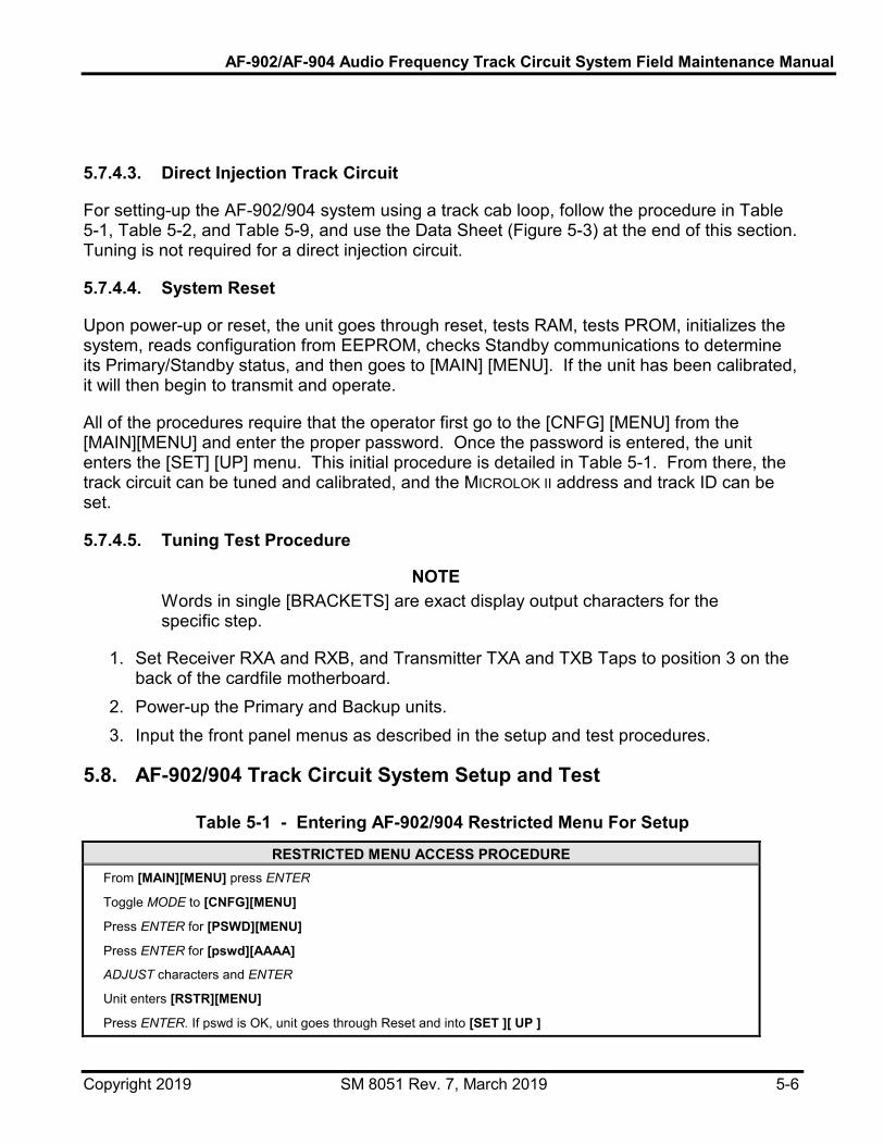
AF-902/AF-904 Audio Frequency Track Circuit System Field Maintenance Manual
Copyright 2019 SM 8051 Rev. 7, March 2019 5-6
5.7.4.3. Direct Injection Track Circuit
For setting-up the AF-902/904 system using a track cab loop, follow the procedure in Table 5-1, Table 5-2, and Table 5-9, and use the Data Sheet (Figure 5-3) at the end of this section. Tuning is not required for a direct injection circuit.
5.7.4.4. System Reset
Upon power-up or reset, the unit goes through reset, tests RAM, tests PROM, initializes the system, reads configuration from EEPROM, checks Standby communications to determine its Primary/Standby status, and then goes to [MAIN] [MENU]. If the unit has been calibrated, it will then begin to transmit and operate.
All of the procedures require that the operator first go to the [CNFG] [MENU] from the [MAIN][MENU] and enter the proper password. Once the password is entered, the unit enters the [SET] [UP] menu. This initial procedure is detailed in Table 5-1. From there, the track circuit can be tuned and calibrated, and the MICROLOK II address and track ID can be set.
5.7.4.5. Tuning Test Procedure
NOTE Words in single [BRACKETS] are exact display output characters for the specific step.
1. Set Receiver RXA and RXB, and Transmitter TXA and TXB Taps to position 3 on the back of the cardfile motherboard.
2. Power-up the Primary and Backup units. 3. Input the front panel menus as described in the setup and test procedures.
5.8. AF-902/904 Track Circuit System Setup and Test
Table 5-1 - Entering AF-902/904 Restricted Menu For Setup
RESTRICTED MENU ACCESS PROCEDURE From [MAIN][MENU] press ENTER
Toggle MODE to [CNFG][MENU]
Press ENTER for [PSWD][MENU]
Press ENTER for [pswd][AAAA]
ADJUST characters and ENTER
Unit enters [RSTR][MENU]
Press ENTER. If pswd is OK, unit goes through Reset and into [SET ][ UP ]

AF-902/AF-904 Audio Frequency Track Circuit System Field Maintenance Manual
Copyright 2019 SM 8051 Rev. 7, March 2019 5-7
Table 5-2 - AF-902/904 MLOK Address and Track Circuit ID Settings
STEP SETTING THE MLOK ADDRESS SETTING THE TRACK CIRCUIT ID NUMBER 1 Obtain track circuit MLOK address from hardware drawings. Obtain track circuit ID from Control Line drawings.
2
Traverse restricted menu as described in Table 5-1.
[SET ][ UP ]
Press ENTER for [TUNE][MENU]
Traverse restricted menu as described in Table 5-1.
[SET ][ UP ]
Press ENTER for [TUNE][MENU]
3
Toggle MODE to [MLOK][MENU]
Press ENTER for [addr][ xx]
ADJUST addr (1-31)
Press ENTER for [MLOK][MENU]
Press ESCAPE for [SET ][ UP ]
Toggle MODE to [AC- ][CEPT]
Toggle MODE to [ ID ][MENU]
Press ENTER for [tkid][xxxx]
ADJUST tkid (0-4095)
Press ENTER for [ ID ][MENU]
Press ESCAPE for [SET ][ UP ]
Toggle MODE to [AC- ][CEPT]
4
Press ENTER for [CON-][FIRM]
Press ENTER to scroll through all parameter settings.
* Accept by pressing ENTER.
* Reject by pressing ESCAPE.
Press ENTER for [CON-][FIRM]
Press ENTER to scroll through all parameter settings.
* Accept by pressing ENTER.
* Reject by pressing ESCAPE.
5
If all parameters are CONFIRMED, unit will write setup parameters to EEPROM and [DONE]
Press ENTER for system reset.
Record track circuit MLOK Addr on Track Circuit Data Sheet (Figure 5-2).
If all parameters are CONFIRMED, unit will write setup parameters to EEPROM and [DONE]
Press ENTER for system reset.
Record track circuit ID on Track Circuit Data Sheet (Figure 5-2).

AF-902/AF-904 Audio Frequency Track Circuit System Field Maintenance Manual
Copyright 2019 SM 8051 Rev. 7, March 2019 5-8
5.8.1. AF-902/904 350 or 500 MCM Track Circuit Setup
For setup of an AF-900/904 350 or 500 MCM track circuit, proceed with instructions in Table 5-3 and Table 5-5.
Table 5-3 - AF-902/904 350 or 500 MCM Tuning Instructions
STEP AF-900 OPERATOR TRACK/COUPLING UNIT TECHNICIAN(S)
1 Obtain track circuit frequency, (Fc) from Control Line Drawings.
Set both coupling units to nominal capacitor setting vs. frequency from Table 5-4.
2
Traverse restricted menu as described in Table 5-1 to
[SET ] [ UP ]
Press ENTER for [TUNE][MENU]
Verify that coupling unit JMP9 {JMP16} is set to "NORM" position.
3 Press ENTER to automatically set direction of signal travel (West to East)
Using Fluke Scopemeter 97 in Vac mode – Monitor voltage at: TP2 and TP1 {TP5 and TP6}.
4
Press ENTER for [freq][0.0]
Toggle AUX to set frequency to Fc-400.
Press ENTER for [pwr][ xx%]
Set pulsewidth to [pwr][50%]
Unit is now transmitting.
Tune EAST coupling unit.
Vary capacitance with JMP1-JMP8 {JMP10-JMP17} to peak voltage across:
TP2 and TP1 {TP5 and TP6}
5 Record final capacitance (W->E) on Track Circuit Data Sheet (Figure 5-2).
6 Press ENTER to automatically set direction of signal travel (East to West).
7
Press ENTER for [freq][ 0.0]
Toggle AUX to set frequency to Fc-400.
Press ENTER for [pwr ][ xx%]
Set pulsewidth to [pwr ][ 50%]
Unit is now transmitting.
Tune WEST coupling unit.
Vary capacitance with JMP1-JMP8 {JMP10-JMP17} to peak voltage across:
TP2 and TP1 {TP5 and TP6}
8 Record final capacitance (W->E) on Track Circuit Data Sheet (Figure 5-2).
9 Press ENTER to complete tuning sequence and return to [TUNE][MENU]

AF-902/AF-904 Audio Frequency Track Circuit System Field Maintenance Manual
Copyright 2019 SM 8051 Rev. 7, March 2019 5-9
Table 5-4 - Coupling Unit (Nominal Capacitance Setting)
NOTE: FINAL TUNED SETTINGS WILL BE NOMINAL ± 2.0 µF (MICRO FARADS). FREQ.(FC) 9.5kHZ 10.5 11.5 12.5 13.5 14.5 15.5 16.5 NOM. CAP. 20.0 µF 17.33 µF 15.00 µF 13.00 µF 11.00 µF 9.47 µF 8.47 µF 7.33 µF
Table 5-5 - AF-902/904 350 or 500 MCM Calibration Procedure
STEP AF-902/904 OPERATOR TRACK/COUPLING UNIT TECHNICIAN(S)
1 Obtain track circuit frequency, (Fc) from Control Line Drawings.
2
Traverse restricted menu as described in Table 5-1 to
[SET][UP]
Press ENTER for [TUNE][MENU]
Toggle MODE to [CALI][BRAT]
Press ENTER for [freq][xx.x]
ADJUST frequency to Fc.
3
Press ENTER to automatically set direction of signal travel (West to East).
Press ENTER for [pwr][xx%].
Unit is now transmitting.
4
Select appropriate transmitter tap and ADJUST [pwr ][ xx%] to set Irail for W to E.
(For Irail setting, refer to
Table 5-6 or Table 5-7).
Using a Spectrum Analyzer with a Current Probe, attach Probe to Center of 350 or 500 MCM Bond and monitor/report rail current (Irail) at East track bond.
5 Record Irail, transmitter tap and pwr for W->E on Track Circuit Data Sheet (Figure 5-2).
NOTE: At cross-bonding points, the S-bond is doubled. The resulting Irail is the sum.
6 Press ENTER to automatically set direction of signal travel (East to West).
Move to West track bond.
7
Press ENTER for [pwr][xx%].
ADJUST [pwr ][ xx%] to set Irail for E to W.
(For Irail setting, refer to
Table 5-6 or Table 5-7).
Using a Spectrum Analyzer with a Current Probe, attach Probe to Center of 350 or 500 MCM Bond and monitor/report rail current (Irail) at West track bond.
8 Record Irail and pwr on Track Circuit Data Sheet (Figure 5-2)..
9
Press ENTER for [Levl][xx%].
Set Receiver tap that produces lowest Levl within range of 18% < Levl < 77%.
Record receiver tap and Levl for E->W on Track Circuit Data Sheet (Figure 5-2).

AF-902/AF-904 Audio Frequency Track Circuit System Field Maintenance Manual
Copyright 2019 SM 8051 Rev. 7, March 2019 5-10
Table 5-5 - AF-902/904 350 or 500 MCM Calibration Procedure STEP AF-902/904 OPERATOR TRACK/COUPLING UNIT TECHNICIAN(S)
10
Press ENTER for [Vari][ x%]
Record [Vari][ x%] for E->W
Press ENTER for [Shnt][151 - 171%]
Record [Shnt][151 - 171%] for E->W when unshunted.
< Vari is the MAX variance of < Fm or Fs from Fc and should be within 0-7%.
< Shnt displays received level < w.r.t. shunt threshold.
11 Note: When SHUNT applied, check that [Shnt][ xx%] < 100%.
Record [Shnt][ xx%] when shunted
Apply 0.2 ohms shunt to track at center of West Bond.
12 Press ENTER to automatically set direction of signal travel (West to East)
13
Press ENTER for [Levl][ xx%]
Check that 20% < Levl < 80%
Record [Levl][ xx%]
Press ENTER for [Vari][ x%]
Record [Vari][ x%] for W->E
Press ENTER for [Shnt][151 - 171%]
Record [Shnt][151 - 171%] for W->E when unshunted.
14 NOTE: When SHUNT applied, check that [Shnt][ xx%] < 100%.
RECORD [Shnt][xx%] when shunted.
Shunt track w/ 0.2ohms at East Bond.
15
Press ENTER for [AC- ][CEPT]
Press ENTER for [CON-][FIRM]
Press ENTER and scroll through all parameter settings.
* Accept by pressing ENTER.
* Reject by pressing ESCAPE.
Note: During accept mode, parameter values will be written to both displays. DO NOT ACCEPT if display values differ.
16 If all parameters are CONFIRMED, unit will write setup parameters to EEPROM and [DONE]. Press RESET button for system reset.
After reset, system LEDs should show by being lit: CPS ACTIVE, ON-LINE, SELF, MLOK COMM, LEVEL, DATA.
Table 5-6 - Rail Current Settings (350 MCM, 500 MCM, and Cab Loop Circuits)
NOMINAL IRAIL CURRENT ± 2 MILLIAMP. FREQ.(FC) kHz 9.5 kHz 10.5 11.5 12.5 13.5 14.5 15.5 16.5
NOMINAL IRAIL (mA) 105 95 87 80 75 70 65 60

AF-902/AF-904 Audio Frequency Track Circuit System Field Maintenance Manual
Copyright 2019 SM 8051 Rev. 7, March 2019 5-11
Table 5-7 - Rail Current Settings (Direct Injection Circuits)
NOMINAL IRAIL CURRENT ± 2 MILLIAMP. FREQ.(FC) kHz 9.5 kHz 10.5 11.5 12.5 13.5 14.5 15.5 16.5
NOMINAL IRAIL (mA) 105 95 87 80 75 70 65 60
For the AF-902, power down the Primary unit and repeat the calibration procedure for the Backup unit.
NOTE Backup unit must have same MLOK address, TRK ID, Fc, password, and executive software version as the Primary unit.
Table 5-8 - AF-902/904 Cab Loop Track Circuit Setup
STEP AF-902/904 OPERATOR TRACK/COUPLING UNIT TECHNICIAN(S)
1
Traverse restricted menu as described in Table 5-1 to
[SET ] [ UP ]
Press ENTER for [TUNE][MENU] Toggle MODE to [CALI][BRAT].
Press ENTER for [freq][xx.x].
ADJUST frequency to [freq][16.5] .
Note: All cab loops employ a single coupling unit at the transmit end.
The AF-902/904 system does not receive a signal back from the track.
2
Press ENTER for [DIR ][W->E].
Press ENTER for [pwr ][ xx%].
Check cab loop wiring to ensure proper connections.
AF-902/904 signal wire to 1,2 {4,5} .
Cab loop wire to 7,8 {10,11}.
3 Select appropriate transmitter tap and ADJUST [pwr ][ xx%] to set ICabloop to 275mA for Cab loop.
Using a Spectrum Analyzer with a Current Probe, attach probe to cab loop wire and monitor/report loop current (Iloop) to the Train Control and Communications Building (TCCB).
4 Record Iloop, transmitter tap and pwr for CAB LOOP on Track Circuit Data Sheet (Figure 5-2).
If location is a double crossover, proceed to other cab loop.
5 Press ENTER for [DIR ][E->W].
6
Check cab loop wiring to ensure proper connections.
AF-902/904 signal wire to 1,2 {4,5} .
Cab loop wire to 7,8 {10,11}.

AF-902/AF-904 Audio Frequency Track Circuit System Field Maintenance Manual
Copyright 2019 SM 8051 Rev. 7, March 2019 5-12
Table 5-8 - AF-902/904 Cab Loop Track Circuit Setup STEP AF-902/904 OPERATOR TRACK/COUPLING UNIT TECHNICIAN(S)
7
Press ENTER for [pwr ][ xx%].
ADJUST [pwr ][ xx%] to the same "pwr" value set in step 3.
Check that the ICabloop > 250mA.
Using a Spectrum Analyzer with a Current Probe, attach Probe to Cab loop wire and monitor/report loop current (Icabloop) to TCCB.
8 Record Icabloop and pwr on Cab Loop Circuit Sheet.
(See NOTE in next column).
Note: Connect VOLTREX jumper wires from auxiliary PCB transmitter outputs to Record inputs.
9
Press ENTER to scroll through remaining menus to: [AC- ][CEPT].
(Disregard Levl, Vari and Shnt readings, See NOTE ->> ).
Press ENTER for [CON-][FIRM].
Press ENTER and scroll through all parameter settings.
* Accept by pressing ENTER.
* Reject by pressing ESCAPE.
Note: During accept mode, parameter values will be written to both displays. DO NOT ACCEPT if display values differ.
10
If all parameters are CONFIRMED, unit will write setup parameters to EEPROM and [DONE] Press RESET button for system reset.
Note: After reset, system LEDs should be illuminated:
CPS ACTIVE, ON-LINE, SELF, MLOK COMM,
(LEVEL & DATA off).
Table 5-9 - AF-902/904 Direct Injection Track Circuit Setup
STEP AF-902/904 OPERATOR TRACK/COUPLING UNIT TECHNICIAN(S)
Proceed step by step with the calibration procedure in Table 5-5.
Proceed step by step with calibration procedure in Table 5-5.
Exception Notes:
(STEP 4 AND STEP 8)
Check coupling unit wiring.
AF-902/904 signal wire to 1, 2 {4, 5}
Track Inject wire to 6, 8 {9, 11}
Irail settings to be done with 0.20 ohm shunt in place across rail at receive end.
Current transformer on shunt.

AF-902/AF-904 Audio Frequency Track Circuit System Field Maintenance Manual
Copyright 2019 SM 8051 Rev. 7, March 2019 5-13
5.9. Test Documentation and Data Sheets
The results of the setup and test procedures must be fully documented using the approved circuit plans and the test Data Sheets. For specific information concerning a particular location’s AF-902/904 installation, refer to that location’s circuit drawings, Book of Plans, test record sheets, and any other installation data that may be available. The type of information that is available may vary and depends on the railroad or transit authority’s record keeping policy.
The approved circuit test plans are used to record the results of the setup procedure. A circuit that has been tuned only should be checked in blue. A circuit that has been both tuned and calibrated should be checked in green. If corrections to the circuit plans are required as a result of any procedure, the Test Engineer should document the changes using Yellow=Out and Red=In color coding. In addition, the test engineer is required to initial and date the changes and to further document the changes by using a Standard Discrepancy/Action Item List with the installation test procedures to fully describe the discrepancy and the action taken.
The Data Sheets provided at the end of this section are used to record the results of the tests. The top portion of the Data Sheet should be filled in before beginning the test. As part of this, the test engineer should record the track circuit length and the approximate cable length from the TCCB to the nearest coupling unit.
Refer to the following test data sheets:
Figure 5-2 - AF-902 Track Circuit Data Sheet
Figure 5-3 - AF-902 Cab Loop Data Sheet
Figure 5-4 - AF-904 Track Circuit Data Sheet
Figure 5-5 - AF-904 Cab Loop Data Sheet.

AF-902/AF-904 Audio Frequency Track Circuit System Field Maintenance Manual
Copyright 2019 SM 8051 Rev. 7, March 2019 5-14
AF-902 TRACK CIRCUIT DATA SHEET
Location __________________________________________________________ Track Circuit Length (100-1000 ft, 30-305 m)_______________Feet/Meters Cable Length to Nearest Bond (100-1000 ft, 30-305 m)________Feet/Meters Track Circuit ID# (1-4095)______________ MLOK Address (1-127)__________
Tuning Procedure
Frequency (kHz)
9.5 10.5 11.5 12.5 13.5 14.5 15.5 16.5
Direction West to East East to West
Coupling Unit Capacitance
___________________________µF
___________________________µF
Calibration Procedure
Transmitter Tap Setting 1 2 3 4 5
Direction West to East East to West
AF-902 Unit Primary Backup Primary Backup
[pwr] Pulse Width (20% - 95%)
____________%
____________%
____________%
____________%
ΙRAIL(mA) ___________mA
___________mA
___________mA
___________mA
Receiver Tap Setting 1 2 3 4 5
Receiver Level [Levl] [Vari]
____________
% 20-80%
____________%
____________
% 20-80%
____________%
____________
% 20-80%
____________%
____________
% 20-80%
____________%

AF-902/AF-904 Audio Frequency Track Circuit System Field Maintenance Manual
Copyright 2019 SM 8051 Rev. 7, March 2019 5-15
0-7% 0-7% 0-7% 0-7%
Shunt Level [Shnt] Unshunted [Shnt] Shunted
____________
% 151 - 171%
____________%
< 100%
____________
% 151 - 171%
____________%
< 100%
____________
% 151 - 171%
____________%
< 100%
____________
% 151 - 171%
____________%
< 100%
Inspector___________________________________________ Date____________________
Figure 5-2 - AF-902 Track Circuit Data Sheet AF-902 CAB LOOP DATA SHEET
Location __________________________________________________________ Cable Length to Cab Loop Coupling Unit (100-1000 ft, 30-305 m)_____Ft/m Track Circuit ID# (1-4095)____________ MLOK Address (1-127)___________
Calibration Procedure
Frequency (kHz)
9.5 10.5 11.5 12.5 13.5 14.5 15.5 16.5
Transmitter Tap Setting 1 2 3 4 5
Direction West to East East to West
AF-902 Unit Primary Backup Primary Backup
[pwr] Pulse Width (20% - 95%)
____________%
____________%
____________%
____________%
ΙCABLOOP(mA)
250mA < I < 300mA
___________mA
___________mA
___________mA
___________mA
Receiver Tap Setting
1 2 3 4 5
(Not Applicable)

AF-902/AF-904 Audio Frequency Track Circuit System Field Maintenance Manual
Copyright 2019 SM 8051 Rev. 7, March 2019 5-16
Inspector___________________________________________ Date____________________
Figure 5-3 - AF-902 Cab Loop Data Sheet

AF-902/AF-904 Audio Frequency Track Circuit System Field Maintenance Manual
Copyright 2019 SM 8051 Rev. 7, March 2019 5-17
AF-904 TRACK CIRCUIT DATA SHEET
Location __________________________________________________________ Track Circuit Length (100-1000 ft, 30-305 m) _______________Feet/Meters Cable Length to Nearest Bond (100-1000 ft, 30-305 m)________Feet/Meters Track Circuit ID# (1-4095)______________ MLOK Address (1-127)__________
Tuning Procedure
Frequency (kHz)
9.5 10.5 11.5 12.5 13.5 14.5 15.5 16.5
Direction West to East East to West
Coupling Unit Capacitance
___________________________µF
___________________________µF
Calibration Procedure
Transmitter Tap Setting 1 2 3 4 5
Direction West to East East to West
[pwr] Pulse Width (20% - 95%)
____________%
____________% ΙRAIL(mA) ___________mA ___________mA
Receiver Tap Setting 1 2 3 4 5
Receiver Level [Levl] [Vari]
____________%
20-80% ____________%
0-7%
____________%
20-80% ____________%
0-7%

AF-902/AF-904 Audio Frequency Track Circuit System Field Maintenance Manual
Copyright 2019 SM 8051 Rev. 7, March 2019 5-18
Shunt Level [Shnt] Unshunted [Shnt] Shunted
____________%
151 - 171% ____________%
< 100%
____________%
151 - 171% ____________%
< 100%
Inspector___________________________________________ Date____________________
Figure 5-4 - AF-904 Track Circuit Data Sheet
AF-904 CAB LOOP DATA SHEET
Location __________________________________________________________ Cable Length to Cab Loop Coupling Unit (100-1000 ft, 30-305 m)_____Ft/m Track Circuit ID# (1-4095)____________ MLOK Address (1-127)___________
Calibration Procedure
Frequency (kHz)
9.5 10.5 11.5 12.5 13.5 14.5 15.5 16.5
Transmitter Tap Setting 1 2 3 4 5
Direction West to East East to West
[pwr] Pulse Width (20% - 95%)
____________%
____________% ΙCABLOOP(mA)
250mA < I < 300mA
___________mA
___________mA
Receiver Tap Setting
1 2 3 4 5
(Not Applicable)

AF-902/AF-904 Audio Frequency Track Circuit System Field Maintenance Manual
Copyright 2019 SM 8051 Rev. 7, March 2019 5-19
Inspector___________________________________________ Date____________________
Figure 5-5 - AF-904 Cab Loop Data Sheet

AF-902/AF-904 Audio Frequency Track Circuit System Field Maintenance Manual
Copyright 2019 SM 8051 Rev. 7, March 2019 5-20

AF-902/AF-904 Audio Frequency Track Circuit System Field Maintenance Manual
Copyright 2019 SM 8051 Rev. 7, March 2019 6-1
6. Preventive Maintenance 6.1. Introduction
This section describes the maintenance tasks required for the AF-902/904 track circuit unit, coupler, and AF-902/904 350 or 500 MCM bond. These preventive maintenance tasks are to be performed on as-scheduled basis, whereby the components are inspected, cleaned, tested, and adjusted at periodic intervals to ensure the proper operation of the AF-902/904 unit.
6.2. Importance of Preventive Maintenance
Regular Preventive Maintenance Inspection (PMI) can prevent failures and system malfunctions.
Maintenance personnel are responsible to keep the AF-902/904 unit in safe and satisfactory operating condition at all times. This is accomplished through regular inspections, cleaning, testing, and required adjustments of the unit. By maintaining up-to-date repair and PMI records, and reviewing the history of these activities, maintenance schedules can be set to prevent circuit performance deterioration. PMI can lead to the discovery of questionable conditions before major malfunctions can occur, potentially causing train traffic problems and eventually total train stoppage.
Track circuit bobbling can affect the Service Availability of the Metro because of the added logic [Summer of 2003] called ‘Sequential Track Circuit Logic’. Any AF-902 track circuit that experiences a bobble requires the reset of the MICROLOK II unit [not recommended by STS USA because errors are accumulated and if not cleared, MICROLOK II will go off line] OR running a sweep train in the control area in order to get the system back to normal operation.
Track circuit bobbles can be minimized by both corrective and preventive maintenance practices. Preventive maintenance is the monitoring of specific parameters in a timely manner. Corrective maintenance is the replacement of a failed unit in a timely fashion.
There are several key parameters of the AF-902 track circuit that can be monitored to determine the health of the track circuit. These parameters are displayed by the AF-902 and can be checked by the maintainer.
The three major AF-902 track circuit parameters to be monitored are:
• Received Signal Level - This parameter is important because it can be used to convey information to the maintainer about the amount of overdrive currently being received by the track circuit. If this overdrive is slightly above 100%, the track circuit has the potential of producing a bobble.

AF-902/AF-904 Audio Frequency Track Circuit System Field Maintenance Manual
Copyright 2019 SM 8051 Rev. 7, March 2019 6-2
• Auto-Calibration - This function is also discussed in detail including the results of using this feature of the AF-902. The received signal level can be read at any time without disrupting the track circuit.
• Error Codes - There are only a few error codes that help the maintainer monitor the health of the track circuit during preventive maintenance activities. The other error codes are observed during corrective action to restore a track circuit back to normal operation after a hardware failure. The error codes can be read at any time without disrupting the track circuit.
• Variance - This parameter can be used to determine whether the coupling unit is tuned correctly or a coupling unit has failed. Variance can also indicate whether interference from another source is becoming a problem in the reliable operation of the track circuit. The variance measurement requires that the track circuit be removed from operation.
Each of the three characteristics listed above are discussed in detail in the following sections.
6.2.1. Received Signal Level
A model of the AF-902 track circuit can be represented as shown in Figure 6-1. The rails are represented by impedance ZR. ‘Bal’ is the ballast resistance of the track circuit.
RT
S
RR
ZR ZR
Bal
Rail Impedance AF-902Receiver
AF-902Transmitter
Figure 6-1 - Direct Injection AF 902 Track Circuit
The AF-902 receiver and its coupling unit are represented as impedance RR and the AF-902 transmitter and its coupling unit are represented as a RT and source voltage S.

AF-902/AF-904 Audio Frequency Track Circuit System Field Maintenance Manual
Copyright 2019 SM 8051 Rev. 7, March 2019 6-3
The value of the ballast resistance changes with time and the conditions of the material that supports the rails. The lower the value of ballast resistance, the lower the signal magnitude received at the input of the AF-902 receiver.
The signal strength received at the input of the receiver is displayed on the front panel of the AF-902. The signal strength is displayed as a percentage. A value of 100% represents the threshold of the receiver. Thus, values of signal strength should be much greater than 100% when the track circuit is not occupied. Typical values of between 150-160% are normal.
If the ballast becomes low, the percent displayed will be less than the normal value.
6.2.1.1. Auto-Calibration Function of the AF-902 System
The AF-902 track circuit is initially adjusted with high ballast resistance. The inherent design of the AF-902 track circuit ensures that it functions correctly over a range of 100%-162%, represented by a term called overdrive. This overdrive is illustrated in Figure 6-2.
100 mA represents 100% Over Drive
62 mA represents 162% Over Drive
AF9
02R
ecei
verT
hres
hold
Figure 6-2 - Adjustment at High Ballast
When the track circuit is initially adjusted (for example, a 10.5 kHz circuit) with high ballast resistance, the threshold level of the track circuit’s receiver is 100 mA. The 100 mA represents an overdrive value of 1 or, expressed in percentage, 100%.
With only an overdrive of 100% (or 1), the track circuit would become occupied if the ballast resistance changes to any lower value than assumed at the initial adjustment value. So it can operate over a changing ballast value, overdrive is added to the track circuit. A track circuit with no overdrive would operate very unreliably.

AF-902/AF-904 Audio Frequency Track Circuit System Field Maintenance Manual
Copyright 2019 SM 8051 Rev. 7, March 2019 6-4
The overdrive can be achieved via increasing the source voltage OR decreasing the threshold value of the receiver. With the AF-902 track circuit, overdrive is obtained by changing the threshold of the receiver. Thus in the figure above, an overdrive value of 1.62 (or 162%) is obtained by adjusting the receiver threshold to 62 mA. Note that the magnitude of overdrive is selected as a function of frequency, shunting sensitivity, minimum ballast, rail-to-rail voltage, etc.
Once the track circuit is adjusted with high ballast resistance, the received signal strength can change as the ballast changes. The value of the received signal strength is displayed on the front panel of the AF-902.
If the track circuit is calibrated using the Auto-Calibration function, the threshold of the receiver will be changed. For example, if the ballast value is low and the received signal level is 100%, performing Auto-Calibration will adjust the threshold of the receiver to a new value.
Figure 6-3 shows the new threshold of the receiver. The new value is now 38 mA, which represents a 162% overdrive value.
For safety reasons, the maximum overdrive is monitored in the AF-902 track circuit. This monitoring of the overdrive is necessary so that the shunting sensitivity of the track circuit does not change.
6.2.1.2. Auto-Calibration During Low-Ballast Conditions
If after an auto-calibration, the ballast would change back to a very high value, the overdrive is much more now than the 162%. See Figure 6-4.
As can be reasoned, the 38 mA threshold now represents an overdrive of 263% (2.63 = 100 mA / 38 mA). Because of the safety implications, the value of overdrive is continuously monitored by the AF-902 track circuit. If this value exceeds approximately 180%, the track circuit is ‘turned off’ for a period of time and Error Code 85 is recorded.
Error 85 is a critical error (refer to Section 7.3.2). The AF-902 will attempt to restore five times with Error Code 85 before it completely shuts down.
The Auto-Calibration function, when performed with low ballast, does not present a safety issue, only a reliability issue in operation. The Auto-Calibration should only be performed when the ballast is high. The overdrive of the AF-902 should be sufficient to permit the track circuit to operate over the complete ballast range.
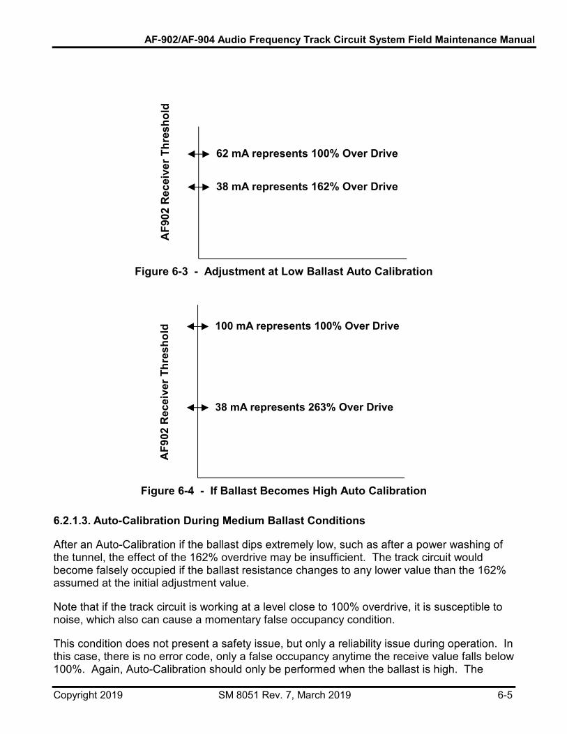
AF-902/AF-904 Audio Frequency Track Circuit System Field Maintenance Manual
Copyright 2019 SM 8051 Rev. 7, March 2019 6-5
62 mA represents 100% Over Drive
38 mA represents 162% Over Drive
AF9
02R
ecei
verT
hres
hold
Figure 6-3 - Adjustment at Low Ballast Auto Calibration
100 mA represents 100% Over Drive
38 mA represents 263% Over Drive
AF9
02R
ecei
verT
hres
hold
Figure 6-4 - If Ballast Becomes High Auto Calibration
6.2.1.3. Auto-Calibration During Medium Ballast Conditions
After an Auto-Calibration if the ballast dips extremely low, such as after a power washing of the tunnel, the effect of the 162% overdrive may be insufficient. The track circuit would become falsely occupied if the ballast resistance changes to any lower value than the 162% assumed at the initial adjustment value.
Note that if the track circuit is working at a level close to 100% overdrive, it is susceptible to noise, which also can cause a momentary false occupancy condition.
This condition does not present a safety issue, but only a reliability issue during operation. In this case, there is no error code, only a false occupancy anytime the receive value falls below 100%. Again, Auto-Calibration should only be performed when the ballast is high. The

AF-902/AF-904 Audio Frequency Track Circuit System Field Maintenance Manual
Copyright 2019 SM 8051 Rev. 7, March 2019 6-6
overdrive of the AF-902 should be sufficient to permit the track circuit to operate over the complete ballast range.
Until recently, Auto-Calibration has been predominantly performed on direct injection track circuits. The recent change of removing all 50 ohm resistors and replacing them with 5 ohm resistors in all direct injection coupling units mitigates the need to perform Auto-Calibration on these track circuits.
6.2.2. Error Code Monitoring
Some of the most common AF-902 track circuit error codes are listed in Table 6-1 to help expedite preventive maintenance on the track circuits. This is a subset of the complete set of error codes described in Section 7.3.2. All other error codes describe specific hardware failures.
Table 6-1 - Common AF-902 Error Codes
ERROR CODE
DESCRIPTION COMMENTS
39 Test failed on the vital parallel output monitor
Either the vital monitor has failed OR noise is detected on the leads connected to the VPO terminals.
57 Standby unit is on line For some reason, the normal unit has failed and the standby unit is on line.
70 Power up or reset of the track circuit The track circuit has been reset by the controls on the front panel or a power-up situation.
85 Over-energized track circuit High output drive OR because of the Auto-Calibration the AF-902 is measuring an overdrive greater than approximately180%.
• Error Code 39: This situation that can cause this error code has been mitigated with the placement of 1,000 ohm resistors on the filter PCB attached to the back of the AF-902 cardfile. This resistor terminates the wiring of the Vital Parallel Output [VPO] of the AF-902. Original cause: The wiring in each AF-902 cardfile has the VPO cable in the same cable bundle as the receiver and transmitter cable for the track circuit. As the train approaches the “S” bond, the noise amplitude increases (this noise appears in the Rx leads). The noise in the Rx leads is induced into the wires attached to the VPO. The 1,000 ohm resistor terminates the VPO and reduces the noise at the VPO terminals. If the VPO is not used, the wiring without termination acts as an antenna for electrostatic noise.

AF-902/AF-904 Audio Frequency Track Circuit System Field Maintenance Manual
Copyright 2019 SM 8051 Rev. 7, March 2019 6-7
If the filter PCB is replaced, ensure that a 1,000 ohm resistor is terminating the wiring on the new filter PCB.
All error codes for each track circuit should be logged. After the logging of these errors, the error code memory should be ‘cleared’. The review of error codes should be performed every week during the preventive maintenance procedure.
• Error Code 57: For some reason, the standby unit is now on line. The reason for the normal unit’s failure needs to be analyzed to determine why the unit failed. The normal unit should be repaired and placed on line.
• Error Code 70: This code simply shows that the track circuit was reset. The reason for the reset should be explored.
• Error Code 85: Because of the safety implications, the value of overdrive is continuously monitored by the AF-902 track circuit and if this value exceeds approximately180%, the track circuit is deactivated for a time period, and Error Code 85 is recorded. The AF-902 unit will attempt to get back on line a total of five times. After the fifth time, the unit will remain off line.
6.2.3. Variance
The AF-902 system employs two type of coupling units. One coupling unit is used with S-bond and O-bond track circuits and requires being tuned to the specific operating carrier frequency. The second type of coupling unit is used for all direct injection, single rail AF-902 track circuit configurations. The direct injection coupling unit does not require tuning.
6.2.3.1. S-Bond and O-Bond Track Circuits
If no in-band interference is present, the variance value obtained from the AF-902 display is a measurement of how well the wayside coupling unit is tuned.
Variance is a measurement of the differences in the amplitudes in the wayside coupling unit between the Mark and Space frequencies. The coupling unit is a LC circuit tuned to a specific frequency.
If the variance is 0%, both the Mark and Space frequency amplitudes are identical. See Figure 6-5.
If the coupling unit is slightly off in tuning, the variance is several percent. Ideally, the variance should be zero. However, values up to 7% are acceptable.

AF-902/AF-904 Audio Frequency Track Circuit System Field Maintenance Manual
Copyright 2019 SM 8051 Rev. 7, March 2019 6-8
6.2.3.2. Direct-Inject Track Circuits
Because the direct injection coupling unit is not tuned, the variance measured with these track circuits is very low. Typical values are between 0% and 2%, depending on the cable length between the room and field-located coupling unit.
With no in-band interference, the variance value is a constant magnitude. However, if in-band noise is present, the variance seen on the AF-902 display will vary between values, because the noise adds and subtracts to the Mark and Space signal amplitudes.
Frequency
Am
plitude
Mark F Space F
Variance = 0%
Frequency
Am
plitude
Mark F Space F
Variance > 0%
Figure 6-5 - Meaning of the ‘Variance’ Parameter
6.3. Preventive Maintenance Tasks
Preventive maintenance tasks are to be performed on a scheduled basis, as described in this subsection, to ensure reliable and safe operation of the AF-902 Track Circuits.
6.3.1. Initial Preventive Maintenance Tasks
Table 6-2 lists the key preventive maintenance actions to be taken during the early phases of operation of the AF-902 Track Circuit units or until a regular and stable maintenance regimen

AF-902/AF-904 Audio Frequency Track Circuit System Field Maintenance Manual
Copyright 2019 SM 8051 Rev. 7, March 2019 6-9
is established for all subsystems of the transit system that affect the operation of the track circuits. The time intervals recommended in Table 6-2 can then be made longer.

AF-902/AF-904 Audio Frequency Track Circuit System Field Maintenance Manual
Copyright 2019 SM 8051 Rev. 7, March 2019 6-10
Table 6-2 - Key Preventive Maintenance Actions
ACTION ITEM TIME PERIOD COMMENTS Review the received signal level.
Once every two weeks Note: If levels are consistently less than 160%, the Variance measurement should not be performed until the receiver levels are stable.
Logs should be kept. If low values of received levels are consistently viewed, the cause of these low levels must be analyzed and the problem solved.
Collect the error codes for all track circuits.
Once every two weeks Clear memory after reviewing the error codes.
Analyze ALL error codes. Once every two weeks See the error code section of this document for advice.
Switch over to the standby units.
Once every four weeks This ensures that the standby unit will go on line. Once the standby unit is on line, receive and variance levels should be checked. This test is to ensure the system’s availability remains high.
Check variance values. Once every four weeks Note: The received levels should be ~150-160% before this measurement is made.
Values should range between 0% and 5%. If the values are greater than stated, the coupling unit should be retuned. If after re-tuning the variance is still high, analysis of other causes should be investigated. Several readings should be taken to determine if the variance is steady (not changing because of interference).
Auto-Calibration: Used only to temporarily increase the overdrive of a track circuit, when low received signal levels are noticed.
As required, but monitored every day until the solution to the problem is found and corrected. Note that if the loading problem goes away, the track circuit can fail with an 85 Error Code.
This may be employed to ensure a 162% over drive of the track circuit on a temporary basis. The reason for low receiver levels might be extremely low ballast, coupling unit failing, cable problems, etc. An analysis must be performed to find the problem. If Auto-Calibration is needed, check the track circuit every day.
6.3.2. Equipment Cleaning Procedure
Cleaning is necessary to remove all accumulated dirt and other foreign matter from the AF-902/904 track circuit unit, coupler, and track bonds that form the AF-902/904 system. A six-month cleaning interval is recommended. While cleaning any of these system components, the maintainer must exercise the necessary caution in order not to damage or dislodge any wires or connectors.

AF-902/AF-904 Audio Frequency Track Circuit System Field Maintenance Manual
Copyright 2019 SM 8051 Rev. 7, March 2019 6-11
6.3.2.1. Cleaning Materials
The following cleaning materials are required to effectively clean the unit and remove unwanted debris. The cleaning supplies are of commercial grade and may be purchased from any cleaning supplier.
Item Use
Household Cleaner Mild liquid cleaner used to clean exterior surfaces.
Lint-Free Cloths Used to clean and dry exterior surfaces.
Soft Bristle Brush Used to remove dust and foreign matter from terminal blocks, electrical connections, and equipment surfaces.
Air in Aerosol Can Used to blow out dust and foreign matter from delicate components and electrical surfaces.
6.3.2.2. Equipment Room Cleaning Procedures
When cleaning the AF-902/904 track circuit cardfile in the equipment room, safety warnings should be adhered to and precautions should be taken to prevent personal injury.
WARNING Hazardous voltages and current may be present. Use extreme caution when working near exposed terminals. Never use wet cloths near exposed electrical equipment.
To clean the cardfile, perform the following procedure: 1. Remove dust and dirt from all accessible surfaces using a soft bristle brush.
2. Using compressed air, blow out dust and dirt from inaccessible areas around terminal blocks, fuse holders, and other areas where live electrical conductors are exposed.
CAUTION When using compressed air to blow out dirt and dust particles from cardfiles, always direct air at an angle relative to the PCBs so that damage will not occur to the mounted components.

AF-902/AF-904 Audio Frequency Track Circuit System Field Maintenance Manual
Copyright 2019 SM 8051 Rev. 7, March 2019 6-12
3. Wipe exterior and interior surfaces, not exposed to electrical circuitry, with a lint-free cloth dampened with a solution of water and household cleaner to remove all dirt and foreign matter.
4. Dry all surfaces with lint-free cloth.
5. Using compressed air or a soft bristle brush, remove all dust and dirt particles from cardfiles, wiring and other areas that may not be accessible using standard cleaning methods.
6.3.3. Track Circuit Inspection
Track circuit inspection should take place at least once a year or more frequently, if desired.
This inspection procedure consists of observing the physical condition of the equipment and performing any actions or operations that may affect the function of the item under test. It may be necessary to take appropriate cleaning steps prior to inspection. Knowledgeable maintenance personnel who are familiar with the operational functions of the system should inspect for appearance, smell, sound, and feel of the equipment. Any of these observation methods can alert the maintenance personnel of fault conditions.
6.3.3.1. AF-902/904 Room Equipment
The following inspection procedures should be used: 1. Check the AF-902/904 front panel to ensure that all PCBs are fully inserted. 2. Verify that all PCBs, Primary and Backup for all track circuits, are inserted into their
proper slots.
3. Verify that all PCBs are securely mounted in the guides at the top and bottom.
4. Check that the cable connections to the rear of the cardfile are intact, tight, and free from nicks, cuts, and fraying.
6.3.3.2. Track Side Components
The following inspection procedure should be used: 1. Check all cable connections from the AF-902/904 unit's auxiliary PCB connectors on the
rear panel to the track circuit coupling units for any signs of nicks, breaks, kinks, corrosion, or fraying.
2. Check all cable connections from the AF-902/904 coupling units to the appropriate 350 or 500 MCM bond locations for any signs of nicks, breaks, kinks, corrosion, or fraying.
3. Verify that the inside of the track coupling unit is free from water and any moisture.

AF-902/AF-904 Audio Frequency Track Circuit System Field Maintenance Manual
Copyright 2019 SM 8051 Rev. 7, March 2019 6-13
4. Check all 350 or 500 MCM bond connections for damage, corrosion, and tightness. 5. Check that all PVC tubing is properly secured against the 350 or 500 MCM cable. 6. Check all wayside components for any signs of physical damage, such as cracks in loop
PVC tubing, etc. Check all mounting hardware for tightness and to see if any of the hardware needs to be replaced.
Remove any debris or foreign objects that may hinder the proper operation of the AF-902/904 track circuit system.
NOTE If any fault condition is observed during inspection, it should be corrected immediately. Inform your supervisor at once for proper procedures.
6.3.4. Track Circuit Checks
Track circuit PMI testing is performed to ensure that all circuits are working properly. It can be assumed that the circuits are performing their function to some degree since failures have not been reported prior to the PMI efforts. It is also assumed that the circuits are within operational tolerance. The track circuit checks are performed to verify how much the circuit is in tolerance or how close is it to failure.
The calibration procedure in Section 5.7 is performed to setup the AF-902/904 FSK track circuit using a 350 or 500 MCM bond. The procedure contains two main sections, tuning and calibration. The tuning portion must be performed prior to the calibration procedures. The tuning portion is performed to tune the associated coupling units to the frequency of use. The calibration portion is done to set rail current, shunt detection, and sensitivity.
At least two people are required to perform these procedures: one operator at the AF-902/904 cardfile and one technician at the track coupling unit.
6.3.4.1. Track Circuit Sensitivity
As part of the calibration portion of the routine, the regularly scheduled PMI will require testing for track circuit sensitivity. Before this test can be performed, tuning should be performed in order to tune the two associated coupling units to the desired track circuit frequencies (9.5, 10.5, 11.5, 12.5, 13.5, 14.5, 15.5, 16.5 kHz). The tuning frequency and track circuit sensitivity information can be found on the initial installation track circuit Data Sheet.


AF-902/AF-904 Audio Frequency Track Circuit System Field Maintenance Manual
Copyright 2019 SM 8051 Rev. 7, March 2019 7-1
7. Troubleshooting 7.1. Introduction
This section describes the methods and procedures that can be used by qualified maintainers to identify, test, isolate, and repair faulty conditions in the AF-902/904 track circuit. All repairs will be to the Lowest Repairable Unit (LRU) that is practical for field maintenance situations.
7.2. Approach to Troubleshooting
The process of isolating a failed or faulty component(s) is called “troubleshooting.” This is a carefully planned approach that will lead to identifying the cause of a system's stoppage or abnormal operation.
The responsibility of the maintenance personnel is to locate the cause of failure and repair the condition as soon as possible. This can be accomplished only if a systematic approach is taken by qualified personnel who are familiar with the test equipment and testing procedures. Basic concepts to apply to any troubleshooting situation are listed in Table 7-1.
Table 7-1 - Basic Troubleshooting Concepts
CONCEPT SUGGESTED ACTIONS Observe and analyze the symptom.
The symptom may identify the site location, sub-system, hardware vs. software causes, or cable/communications link.
Sectionalize the system. If it is difficult to identify the faulty subsystem, the maintainer should proceed to sectionalize the system in halves until the site and subsystem are known.
Localize the fault within the Subsystem.
Identify the LRU and test by using available software or control panel diagnostics.
Isolate the cause. Continue troubleshooting the LRU for modular replacement or adjustment.
Repair the failure. The trouble can be corrected by adjustment, component replacement, or wire repair.
Check repair and operation. Verify that the repair has been properly done by checking the operation of the system for any other fault symptoms and irregularities. Never assume that the first fault found was the only fault.
The priority of field maintenance personnel is to get the system up and running. This calls for prompt action, fault isolation, and trouble repair. To achieve this, the Maintainer may not be required to troubleshoot beyond the modular component level, commonly referred to as the LRU level. The entire troubleshooting process can be expedited by performing “Go-No Go” replacement checks and repair.
The key to identifying the probable cause of failures is the use of a process of elimination. This is the most effective and efficient approach to troubleshooting and fault isolation on any system.
AF-902/AF-904 Audio Frequency Track Circuit System Field Maintenance Manual
Copyright 2019 SM 8051 Rev. 7, March 2019 7-2
7.3. Troubleshooting Procedures
7.3.1. Fault Symptoms
Every abnormal symptom is a result of a cause that has a remedy. The maintainer must determine how severe the cause (how much damage resulted), and how difficult the repair process (quick replacement versus system down-time). Table 7-2 gives a brief listing of symptoms, probable causes, and suggested remedies. These remedies are to the LRU level to assist in swift repair.
The ATC system notifies the train dispatcher and general system maintainer of problems by an AF-902 off-line or on-line alarm. • The AF-902 off-line alarm is an indication that either the Primary or the Standby unit has
failed/reset. If the Primary unit fails, then a fail-over occurs to the Standby unit. This event most likely causes a sequential occupancy. If the AF-902 off-line alarm is toggling off and on, then most likely the Standby unit is constantly resetting itself.
• The AF-902 on-line failure alarm turns on only after an AF-902 off-line failure, indicating that both AF-902 units have failed. This causes an occupancy display and stops train movement.
The AF-902/904 FSK track circuit system notifies the maintainer of most faults through its front panel indicators. Before performing any troubleshooting tests or diagnostics, the maintainer should first make the following observations: • Are the power supply LEDs ON? • Are the controller, auxiliary, and supply LEDs NORMAL? • Is a backplane connector loose or disconnected? • Is there any physical damage anywhere near the track circuit equipment?
If no obvious faults are observed, the maintainer should proceed with the standard troubleshooting techniques.

AF-902/AF-904 Audio Frequency Track Circuit System Field Maintenance Manual
Copyright 2019 SM 8051 Rev. 7, March 2019 7-3
Table 7-2 - Troubleshooting
SYMPTOM PROBABLE CAUSE SUGGESTED REMEDY Track is unoccupied, but low or no receive signal.
Broken 350 or 500 MCM bond. Check track bond and cabling.
Bad coupling unit. Check input and output cable connectors to coupling unit.
Defective auxiliary PCB. Remove and replace.
Conductive debris across track. Inspect and remove debris.
Intermittent track occupancy indications.
Signal threshold level setting on auxiliary PCB not correct.
Adjust or replace.
Receiver levels are low. Track carrier frequencies are out of specification limits.
Check tuning procedure. Verify coupling unit adjustment.
When performing the tuning or calibration procedures, the proper carrier frequency cannot be achieved.
Adjacent track circuit ON. Turn power OFF of adjacent track circuit.
Adjusting wrong circuit in coupling unit.
Check for correct TX or RX side of PCB.
Voltage not On-Line (LED OFF) to MICROLOK II.
CPS voltage dropped. Auxiliary or controller PCB faulty. Remove and replace.
No 500 Hz signal on auxiliary PCB test point
MCU failed diagnostic. Check for false track occupancy indications.
HEALTH indicator OFF Primary or Backup unit is faulty. Check LEDs on defective circuit and replace defective module.
The MCU is continually running diagnostics on the entire AF-902/904 track circuit system. Any failure of these diagnostics will signal the MICROLOK II unit of track occupancy. This will maintain the track circuit in a safe state, not allowing any train traffic until the system is again operating correctly.

AF-902/AF-904 Audio Frequency Track Circuit System Field Maintenance Manual
Copyright 2019 SM 8051 Rev. 7, March 2019 7-4
7.3.2. Error Code Observations Table 7-3 provides a list of AF-902 Critical Error Codes and their corresponding diagnostic indications.
Table 7-3 - AF-902 Critical Error Codes
CRITICAL ERROR CODE
DESCRIPTION REMEDY
9 More than two MICROLOK II re-polls occurred in a single AF-902/904 system cycle (360 msec).
Check polling settings for MICROLOK II unit. Cannot send more than one message to a given station every cycle (360 msec). To allow for message delays, minimum time should be 400 msec.
14 Primary and Backup units have configuration data which do not match.
The track ID, center frequency or MICROLOK II address are not the same for both units. Check configuration and re-configure units as necessary.
16 The CRC for the EEPROM data is not correct.
Error with EEPROM (configuration) data. If error persists, re-configure unit. If error still persists, replace the EEPROM (attached to the cardfile).
17 The system was unsuccessful in trying to save data to the EEPROM.
Error with EEPROM (configuration) data. If error persists, re-configure unit. If error still persists, replace the EEPROM (attached to the cardfile).
19 Copy 1 of the EEPROM record (in RAM) did not match copy 2 of the EEPROM record (in RAM).
Error with EEPROM (configuration) data. If error persists, re-configure unit. If error still persists, replace the EEPROM (attached to the cardfile).
20 The EEPROM data has had an unexpected revision number.
Error with EEPROM (configuration) data. If error persists, re-configure unit. If error still persists, replace the EEPROM (attached to the cardfile).
22 Copy 1 (EEPROM) of configuration data does not match Copy 2 (EEPROM).
Error with EEPROM (configuration) data. If error persists, re-configure unit. If error still persists, replace the EEPROM (attached to the cardfile).
Table 7-3 – AF-902 Critical Error Codes (continued)
23 Copy 1 (EEPROM) of block speed does not match Copy 2 (EEPROM). The block speed is over-written to be zero for both copies.
Error with blocking speed in EEPROM (configuration) data. Re-set the blocking speed. If error persists, re-configure unit. If error still persists, replace the EEPROM (attached to the cardfile).

AF-902/AF-904 Audio Frequency Track Circuit System Field Maintenance Manual
Copyright 2019 SM 8051 Rev. 7, March 2019 7-5
30 Incorrect code was returned by the keyboard encoder.
If the error occurs once, ignore it. If this error persists, it indicates a hardware failure of the CPU board. Replace board.
32 Number of accumulated frequency monitor range errors exceeded the limit.
Normally associated with a failure of the Controller board. Replace board.
33 Frequency monitor for center frequency was requested during normal (not configuration mode) operation.
Normally associated with attempting to calibrate a unit with other units in operational mode. All adjoining track circuits should be turned off when calibrating a unit.
34 Incorrect gain was detected for a receive channel. Channel number can be read using dump events feature.
This is a test of the calibration of the track receivers. This is often due to noise from adjoining track circuits causing saturation of the band pass filter. This can normally be corrected by re-calibrating the circuit with a lower tap setting on the track receiver.
35 Rejection level incorrect for low-pass filter. Channel number can be read using dump events feature.
Normally associated with a failure of the Controller board. Replace board.
36 Rejection level incorrect for band-pass filter. Channel number can be read using dump events feature.
Normally associated with a failure of the Controller board. Replace board.
37 Vital Parallel Output (VPO) monitor read an incorrect state at the output.
This usually indicates noise on the vital output when the output is de-energized. Check for, and correct, any external noise sources. This error can also be logged by the Standby unit if Fail-over messages are temporally disrupted at the same time that the occupancy changes state. Can also be associated with a failure of the Controller board. If failure persists, replace board.
38 Vital parallel output monitor read an inconclusive state at the output.
If this is a single occurrence, it is normally noise related. If this error persists, it indicates a hardware failure of the CPU board. Replace board.
Table 7-3 – AF-902 Critical Error Codes (continued)
39 Test of the vital parallel output control monitor circuit failed.
If this is a single occurrence, it is normally noise related. If this error persists, it indicates a hardware failure of the CPU board. Replace board.
If the VPO is unused, check that the terminating resistor is installed by verifying that the appropriate jumper for the track circuit is in position 2-3.

AF-902/AF-904 Audio Frequency Track Circuit System Field Maintenance Manual
Copyright 2019 SM 8051 Rev. 7, March 2019 7-6
40 Pulse test of the vital parallel output failed.
If this is a single occurrence, it is normally noise related. If this error persists, it indicates a hardware failure of the CPU board. Replace board.
47 Ramp test of the digital-to-analog converter and analog-to-digital converter failed.
If this is a single occurrence, it is normally noise related. If this error persists, it indicates a hardware failure of the CPU board. Replace board.
48 Track transmit power amplifier is too high or too low, possibly due to a CPS failure.
If this is a single occurrence, it is normally noise related. If this error persists, it indicates a hardware failure of the AUX board. Replace board. This can also occur when an AUX board is replaced and the unit is not re-configured. Re-configure unit.
49 Malfunction was detected in the power amplifier monitor circuit.
If this is a single occurrence, it is normally noise related. If this error persists, it indicates a hardware failure of the AUX board. Replace board. This can also occur when an AUX board is replaced and the unit is not reconfigured. Reconfigure unit.
55 System mode change from Standby to Off-Line or On-Line to Standby.
Normal Operation.
56 User requested a change in system mode to configuration mode.
Normal Operation.
65 EPROM error was detected.
If this is a single occurrence, it is normally noise related. If this error persists, it indicates a hardware failure of the Executive PROM or the CPU board. Replace the Executive PROMs or the CPU board.
Table 7-3 – AF-902 Critical Error Codes (continued)
66 RAM error was detected.
If this is a single occurrence, it is normally noise related. If this error persists, it indicates a hardware failure of the CPU board. Replace board.
68 System cycle did not complete within 360 msec.
This can be caused by noise on the serial link lines during the end-of-cycle processing. Check for, and correct, noise conditions on the serial link.
69 Elapsed time between 2 msec interrupts was greater than 2 msec.
Software error.
70 Power-up or front panel reset occurred Normal operation.
71 Processor watchdog timed out with no critical error logged. Software error.
75 Fixed register in CPU was found to contain an incorrect value.
Software error.

AF-902/AF-904 Audio Frequency Track Circuit System Field Maintenance Manual
Copyright 2019 SM 8051 Rev. 7, March 2019 7-7
88 Direction relay failed.
If this is a single occurrence, it is normally noise related. If this error persists, it indicates a hardware failure of the CPU board or the direction relays. Replace board or cardfile.
89 Direction relay monitor failed.
If this is a single occurrence, it is normally noise related. If this error persists, it indicates a hardware failure of the CPU board or the direction relays. Replace board or cardfile.
All other critical error codes correspond to internal system errors. Table 7-4 lists all the two-digit codes that can be displayed by the AF-902.

AF-902/AF-904 Audio Frequency Track Circuit System Field Maintenance Manual
Copyright 2019 SM 8051 Rev. 7, March 2019 7-8
Table 7-4 - All AF-902 Error Codes 0 TRKTX_BUF_OVERFLOW 1 FREQMON_BUF_OVERFLOW 2 INVLD_TX_STATE 3 BAD_FILL 4 INVLD_DIRECTION 5 BAD_RX_CHANNEL 6 MISSING_AD_SAMPLE 7 RANGE_ERROR_TRKRXBUF 8 MLK_TX_STATUS 9 MLK_PROCDATA 10 MLK_ADDR 11 BAD_FO_RX_PROC 12 BAD_FO_RX_MODE 13 INVLD_FO_HEADER 14 NON_MATCHING_CONFIG 15 EE_REC_MISMATCH 16 EE_CRC_MISMATCH 17 EE_MAX_REWRITE_ERR 18 EE_ADDRESS_ERROR 19 EE_RECORD_MISMATCH 20 EE_REC_REV_MISMATCH 21 EEPROM_FAILURE 22 CONFIGURATION_MISMATCH 23 BLOCKING_SPEED_MISMATCH 24 UNDEFINED_MENU_INIT_FUNCTION 25 UNDEFINED_MENU_LINK 26 UNDEFINED_PARAMETER_TYPE 27 UNDEFINED_DISPLAY_DESIGNATOR 28 INVALID_MENU_ID 29 DIGIT4_T_CHARACTER_MISMATCH 30 KEYBOARD_ENCODER_ERROR 31 INVALID_TEST_STATE 32 FREQ_MON_FAILURE 33 FREQ_MON_RANGE_ERROR 34 NORMAL_CHANNEL_ERROR 35 LOWPASS_CHANNEL_ERROR 36 BANDPASS_ERROR 37 VPO_MONITOR_MISMATCH_CRIT 38 VPO_MONITOR_INCONCLUSIVE, 39 CONTROL_MONITOR_ERROR 40 VPO_PULSE_ERROR 41 ILLEGAL_TIMER_VALUE 42 TIMER_EXPIRED 43 ILLEGAL_TIMER_STATUS, 44 WATCHDOG_EXPIRED
45 WATCHDOG_OFF 46 TIMER_OUT_OF_RANGE 47 RAMP_TEST_FAILURE 48 POWER_AMP_FAILURE 49 POWER_AMP_MON_FAILURE 50 CPS_FAILURE 51 BAD_CPU16_AD_READ 52 REQSTAT_NOT_PROCESSED 53 ACKSTAT_NOT_PROCESSED 54 INVALID_SYSTEM_MODE 55 MODE_CHANGE 56 CONFIGURATION_REQUEST 57 STBY_TO_ONLINE 58 BAD_TASK_CRC 59 BAD_SYSTEM_MODE 60 TRACK_REQ_CONFLICT 61 INVALID_TRACK_CONFIG_MODE 62 CONFIG_REQ_CONFLICT 63 DP_ERROR 64 DS_ERROR 65 ROM_FAILURE 66 RAM_FAILURE 67 SUBCYCLE_MISMATCH 68 MISSED_CYCLE 69 MISSED_MSEC_IRQ 70 SYSTEM_RESET 71 UNEXPECTED_WATCHDOG_TIMEOUT 72 UNEXPECTED_RESET 73 STACK_OVERFLOW_LOW 74 STACK_OVERFLOW_HIGH 75 FIXED_REGISTER_MISMATCH 76 CCR_SAVE_ERROR 77 CCR_RESTORE_ERROR 78 CPS_KEY_SUM_ERROR 79 BAD_FILL_CHAR 80 ILLEGAL_VALUE 81 CONTROL_FLOW_ERROR 82 POINTER_OUT_OF_RANGE 83 DS_MACRO_ERROR 84 QSPI_TXBUF_OVERFLOW 85 OVER_ENERGIZED_TRACK 86 CONFIGURATION_DONE 87 BAD_MLKMSG_COUNT_OVER

AF-902/AF-904 Audio Frequency Track Circuit System Field Maintenance Manual
Copyright 2019 SM 8051 Rev. 7, March 2019 7-9
7.4. PCB Front Panel Indicators and Controls
7.4.1. AF-902/904 Controller PCB
This front panel consists of two, four-character alphanumeric scrolling displays, and four up-down SPDT toggle switches that can be used to enter and examine data used in the setup and operation of the track circuit. Five LEDs provide additional information. In addition, a front panel PC-compatible serial port and a Background Mode Debugging Port are available. The serial port can be made available to the end user, but the background port is for factory use only.
Additional detailed information is presented in Section 4.2, which describes the full panel controls, indications and functions.
Figure 7-1 illustrates the indications, controls, and other features on the front panel of the Controller PCB.
7.4.2. AF-902/904 Auxiliary PCB
Eight front panel LEDs on the auxiliary PCB indicate the status of various key parameters in a readily interpreted format. • State of Conditional Power Supply; LED On = CPS On. • Status of unit; LED On = On-Line, LED Off = Standby. • Health (availability) of this unit; LED On = unit available. • Health (availability) of partner unit; LED On = unit available. • Status of the link to track MICROLOK II system; LED On = communications established. • Special Block Speed Restriction Status; LED On = block speed set. • Track Signal Level; LED On = track clear. • Track Data Signal; LED On = track clear.
Eleven maintenance test points are also available on the auxiliary PCB front panel. These test points allow for quick checking of system voltages and signal status without removing the PCB for extender mounting.
Figure 7-2 illustrates the indications and maintenance test points on the front panel of the Auxiliary PCB.

AF-902/AF-904 Audio Frequency Track Circuit System Field Maintenance Manual
Copyright 2019 SM 8051 Rev. 7, March 2019 7-10
7.4.3. AF-902/904 Power Supply PCB
The power supply PCB was designed specifically for application in the AF-902/904 track circuit cardfile. It occupies one double-width 6U card slot.
Two separate power switches are on the front panel. They are locking-lever type switches that need to be pulled out in order to toggle. Test points and LED indicators for each supply output (six total) are provided and are accessible through the front panel.
Each Power Amplifier Transformer output is also accessible at the front panel. All test points are fed through appropriate current limiting resistors to avoid shorting the outputs. All resistors will not exceed the 50% rating even when shorted to ground.
A solder-side cover reduces the risk of electrical shock, as there are high voltages (115 Vac ±10%) on the PCB.
Figure 7-3 illustrates the indications, test points, and controls on the front panel of the Power Supply PCB.

AF-902/AF-904 Audio Frequency Track Circuit System Field Maintenance Manual
Copyright 2019 SM 8051 Rev. 7, March 2019 7-11
UP
DOWN
ADJMODE
AUX 1
PRESS TORESET
IN RESETWHEN LIT
ESCAPE
STATUSLEDS 2
1
DIR.W
E
DEBUGPORT
TRK CKTCTRLR
N123603-01
DIAGPORT
ALPHANUMERICLED DISPLAYS
MOTOROLABACKGROUNDDEBUG PORT
(FACTORY USE ONLY)
CONFIGURATION SETUPSWITCHES
MOMENTARY CONTACTSWITCHES
(SPRING RETURN TO CENTER)
SYSTEM MONITORLEDS
SYSTEM RESETPUSHBUTTON
9-PIN PORTFOR
PORTABLE PC(RE-232DTE)
EN TER AUX 2
Figure 7-1 - AF-902/AF-904 Controller PCB Front Panel
AF-902/AF-904 Audio Frequency Track Circuit System Field Maintenance Manual
Copyright 2019 SM 8051 Rev. 7, March 2019 7-12
AUXILIARYBOARD
N12360401
CPS ACTIVE
ON-LINE
SELF
PARTNERHEALTH
U-LOK COMM
BLOCK SPEED SET
LEVEL
DATATRACKCLEAR
P1
P2RECEIVER
INPUT
+12V
+5VVITAL
OUTPUTS
BANDPASS FILTER
ANALOG GROUND
+44V
SYSTEM GROUND
+
-
CPS 500Hz
TRANSMITTEROUTPUT
SYSTEM MONITORLEDS
MAINTENANCETEST POINTS
Figure 7-2 - AF-902/AF-904 Auxiliary PCB Front Panel
AF-902/AF-904 Audio Frequency Track Circuit System Field Maintenance Manual
Copyright 2019 SM 8051 Rev. 7, March 2019 7-13
POWER SUPPLYN12360501
ONOFF
+15V-15V+5V+15V-15V LE
FTPO
WER
SUP
PLY
GND
OFF
0
ON
0
XMFR
+5V+15V-15V
+5V
XMFR
-15V
RIGH
TPO
WER
SUPP
LY
+15V+5V
GND
LOCKINGSUBSYSTEM
POWER SWITCH
AC POWERTEST POINTS
POWERMONITOR
LEDS
DC POWERTEST POINTS
LOCKINGSUBSYSTEM
POWER SWITCH
POWERMONITOR
LEDS
DC POWERTEST POINTS
Figure 7-3 - AF-902/AF-904 Power Supply PCB Front Panel

AF-902/AF-904 Audio Frequency Track Circuit System Field Maintenance Manual
Copyright 2019 SM 8051 Rev. 7, March 2019 7-14

AF-902/AF-904 Audio Frequency Track Circuit System Field Maintenance Manual
Copyright 2019 SM 8051 Rev. 7, March 2019 8-1
8. Corrective Maintenance 8.1. Introduction
This section describes the procedures necessary to access, replace, and repair the AF-902/904 track circuit system’s components to the LRU level that is practical at the field maintenance level.
Corrective maintenance is an unscheduled process initiated by a system failure or resulting from unsatisfactory preventive maintenance data. After a system fault has been localized by performing the necessary troubleshooting and diagnostic testing, the maintainer is required to adjust or replace the component. Following the component adjustment or replacement, the maintainer is required to perform system repair verification.
8.2. Replacement Repair
The AF-902/904 track circuit system comprises three major components: • AF-902/904 FSK cardfile • AF-902/904 track coupling unit • 350 or 500 MCM bond
The suggested repairs at the field level are designed to minimize system downtime and reduce the need for specialized or sophisticated test equipment. The EEPROM is integral to the motherboard and cardfile. Replacing the EEPROM requires the cardfile to be replaced.
8.2.1. AF-902/904 PCB Replacement
The AF-902/904 cardfile holds electronic PCBs in a chassis compatible with a 19-inch wide AF rack. This equipment, which resides in the equipment room, requires a power input of 115 Vac ±10% at 50/60 Hz (nominal).
Section 1.3 describes the physical configuration of the PCBs.
8.2.1.1. Required Tools
The only tool required is a medium-sized, flat-blade screwdriver.
8.2.1.2. Procedure
After having identified the faulty PCB, replace it by following the procedure below: 1. Identify the power supply PCB associated with the track circuit PCB to be replaced.
Figure 8-1 identifies the top circuit of the PCB as Backup power and the bottom circuit as Primary power.
2. Turn OFF the corresponding Locking Subsystem Power Switch.

AF-902/AF-904 Audio Frequency Track Circuit System Field Maintenance Manual
Copyright 2019 SM 8051 Rev. 7, March 2019 8-2
CAUTION Turning ‘OFF’ the wrong Power Switch will cause a general system failure.
3. Turn the captive thumb screws, at the top and bottom of the defective PCB module, counterclockwise until loose.
4. Grasp the Module Ejectors, next to the thumb screws at the top and bottom, and pull the PCB straight out from the board guides. Remove it from the cardfile.
5. Install the replacement PCB in the board guides and slide it in until the PCB engages the cardfile connector.
6. Turn the PCB thumb screws clockwise until they are finger-tight and the PCB is firmly positioned against the cardfile frame.
7. Turn ON the associated Power Switch.
NOTE
When any of the three PCBs is replaced, the calibration procedure should be rerun to verify the settings and update the threshold calculations.
Power supply PCB replacement requires both of the locking subsystem power switches to be turned OFF prior to removing the PCB. This is considered a total system failure and an emergency repair.
8.2.2. Coupling Unit Replacement
The PCB is mounted in an aluminum box, which is installed within 15 feet (4.572 m) of the rail.
The coupling circuit is mounted on a PCB 9” x 13” x 3/32” (22.86 cm x 32.02 cm x .238 cm) thick. This PCB has two identical circuits and two terminal strips for external connection of inputs and outputs. This single PCB is used for two track circuits, the local transmit circuit, and the receiver circuit for an adjacent track circuit.
This unit could be replaced due to either: • Circuit failure • Aluminum box leaking (not water tight)
8.2.2.1. Tools Required
To remove the PCB, a medium-sized, flat-blade screwdriver is required.
AF-902/AF-904 Audio Frequency Track Circuit System Field Maintenance Manual
Copyright 2019 SM 8051 Rev. 7, March 2019 8-3
POWER SUPPLYN12360501
ONOFF
+15V-15V+5V+15V-15V LE
FTPO
WER
SUP
PLY
GND
OFF
0
ON
0
XMFR
+5V+15V-15V
+5V
XMFR
-15V
RIGH
TPO
WER
SUPP
LY
+15V+5V
GND
LOCKINGSUBSYSTEM
POWER SWITCH
AC POWERTEST POINTS
POWERMONITOR
LEDS
DC POWERTEST POINTS
LOCKINGSUBSYSTEM
POWER SWITCH
POWERMONITOR
LEDS
DC POWERTEST POINTS
Figure 8-1 - AF-902/AF-904 Power Supply PCB
AF-902/AF-904 Audio Frequency Track Circuit System Field Maintenance Manual
Copyright 2019 SM 8051 Rev. 7, March 2019 8-4
8.2.2.2. PCB Replacement 1. Turn OFF track circuit power supply on the AF-902/904 FSK cardfile unit in the equipment
room.
WARNING
Make sure that all power is turned off to the track circuit coupling unit prior to performing maintenance or replacement. Hazardous voltages and current are present when power is on.
NOTE Make sure that the correct power supply PCB circuit is turned OFF.
2. Open coupling unit box with recommended tool(s). 3. Remove terminal wires, labeled 1 through 4, at terminal blocks TBl and TB2. Record wire
location and color for reinstallation purposes. 4. Remove the three PCB mounting screws at the corners of the board. 5. Remove the PCB by lifting straight up from the box. 6. Replace defective PCB with new PCB. 7. Reinstall PCB mounting screws. 8. Attach wires to TBl and TB2, according to wire location and color. 9. Perform adjustment and calibration procedures outlined in Section 5. 10. Close and secure aluminum box to ensure water tightness.
8.2.2.3. Coupling Box Replacement
Refer to manufacturer's equipment manual for specific tool requirements.
WARNING Make sure that all power is turned off to the track circuit coupling unit prior to performing maintenance or replacement. Hazardous voltages and current are present when power is on.
1. Detach input and output cables from box connectors. (Two Transmit/Receive cables and
two of the One-Loop cables for the track signal.) 2. Remove aluminum box mounting screws at base if mounted to secured surface.
3. Replace defective coupling unit with operational unit and secure, if required.
4. Reconnect input and output cable wires.
5. Perform Steps 1, 9, and 10 of Subsection 8.2.2.2.

AF-902/AF-904 Audio Frequency Track Circuit System Field Maintenance Manual
Copyright 2019 SM 8051 Rev. 7, March 2019 8-5
8.2.3. Bond Replacement
The bond track circuit is very simple, in both material hardware and function. It consists of a few meters of 350 or 500 MCM heavy conductive cable, typically arranged in an “S” shape between the rails and connected at end points to the rails.
The cables from the coupling units are single loop wires that induce signals into the Loop and into the rails.
Once these cables are installed and verified as operational, there is very little, if anything, that may require replacement. If any damage occurs to this hardware, it will be necessary to refer to the site's equipment and cable plans and the manufacturer's equipment manual.
8.3. Verification of System Repair
To ensure that the repairs have been performed correctly and that all replacement modules are fully functional, a system verification must be performed. This verification procedure uses the AF-902/904 track circuit system test.
This specific test is described in Section 6.3.4 and consists of two procedures, tuning and calibration.
The AF-902/904 tuning procedure performs the following functions: • Entry of carrier frequency • Tuning of both coupling units
The AF-902/904 calibration procedure carries out the following system functions: • Entry of Carrier Frequency, Track ID, and MLOK Address • Setting of the Transmitter Tap and Vout to set rail current (Irail) • Setting of the Receiver Tap and Shunt/Data Threshold • Verification of 0.20 ohm shunt sensitivity

AF-902/AF-904 Audio Frequency Track Circuit System Field Maintenance Manual
Copyright 2019 SM 8051 Rev. 7, March 2019 8-6
NOTE Depending on the repair or replacement that is performed, the tuning procedure may not be required. This is performed as a setup procedure and when a change in the setting of the track circuit frequency is required.
Replacement of AF-902/904 track circuit PCBs does not warrant the tuning procedure. The calibration procedure should, however, be performed to verify the repairs.
Table 8-1 and Table 8-2 contain a summary of these test procedures. Refer to Section 5.7 for detailed procedures.
Table 8-1 - AF-902/904 Tuning Summary STEP AF-902/904 OPERATOR TRACK/COUPLING UNIT TECH
1 From front panel, set Carrier Frequency. Set both coupling units to nominal capacitor setting vs. frequency.
2 Set direction (automatic) (Transmit East to West).
Tune West coupling unit using capacitor jumpers in coupling unit.
3 Set direction (automatic) (Transmit West to East).
Tune East coupling unit using capacitor jumpers in coupling unit.
4 Set direction (automatic) (Transmit East to West) and verify tuning.
Table 8-2 - AF-902/904 Calibration Summary STEP AF-902/904 OPERATOR TRACK/COUPLING UNIT TECH
1 From front panel, set Carrier Frequency, Track ID, MLOK Address.
2 Set direction (automatic) (Transmit West to East).
3 Adjust transmitter taps and Vout to set IRAIL.
Monitor and report rail current (IRAIL) at East track bond.
4 Set direction (automatic) (Transmit East to West).
5 Adjust Vout to set IRAIL for E to W. Monitor and report rail current (IRAIL) at West track bond.
6 Monitor received signal and adjust receiver taps.
7 Initiate threshold calculation. Verify threshold value.
Shunt track with 0.2 ohms at west track bond.
8 Set direction (automatic) (Transmit West to East).
9 Initiate threshold calculation. Verify threshold value.
Shunt track with 0.2 ohms at east track bond.

AF-902/AF-904 Audio Frequency Track Circuit System Field Maintenance Manual
Copyright 2019 SM 8051 Rev. 7, March 2019 9-1
9. Tektronix Setup Procedure This procedure uses the Tektronix TDS 3012B Oscilloscope and Tektronix A621 AC Current Probe to measure AF-902/904 peak currents. It assumes that the user is familiar with the basic operation of the Tektronix TDS 3012B. The procedure also assumes that the basic user settings (language, time, etc.) of the instrument have been configured. It is provided as an aid to setting up the Tektronix equipment prior to the actual tuning of the AF-902/904 system.
The following paragraphs are intended to help the user become familiar with the control layout of the Tektronix TDS 3012B Oscilloscope.
Observe that there are buttons along the bottom and right edge of the display. The function of these buttons will change, depending on other menu button selections. The current functions will be shown on the display.
There is a set of buttons along the top right side of the instrument. Only the Cursor, Select, and Coarse buttons and the adjustment knob between to the Coarse and Cursor buttons will be used in this procedure.
The remaining controls are grouped in four columns: Vertical, Horizontal, Trigger, and Acquire. This procedure will call out a control by Group – Control (button or knob). As an example, if adjustment of the position knob in the Horizontal group is required, the procedure will identify the control as Horizontal – Position.
The following table lists the steps in the setup procedure.

AF-902/AF-904 Audio Frequency Track Circuit System Field Maintenance Manual
Copyright 2019 SM 8051 Rev. 7, March 2019 9-2
Table 9-1 - Tektronix Setup Procedure
STEP NUMBER
CONTROL SETTING OBSERVE
1 Power Switch On Display shows instrument settings box, followed by graduated screen.
2 Current Probe
Range Switch
Connect to CH1 and clamp around AF-902/904 transmitted signal line. Set the Current Probe Range Switch to 10.
3 AF-902/904
Using instructions in this manual, Table 5-5. Set up the AF-902/904 system to transmit a constant center frequency.
4 Acquire – Autoset Press button. Display will show several cycles of the transmitted signal in yellow.
5 Acquire – Menu Press button. Display shows menu of options.
6 Horizontal – Scale Adjust knob until the Sample Rate, lower right corner of display, is 500 KS/s.
7
Vertical - CH1 (yellow)
then
Vertical - ~off
Press sequence to turn off analog signal display. Yellow trace turns off.
8 Vertical – Math (red) Press button. Red trace shows on display, if not already on.
9 Right side of display top button Select FFT source as CH1. Displays CH1.
10 Right side of display 2nd button
Select FFT vertical scale to Linear RMS. Displays Linear RMS.
11 Right side of display 3rd button Select FFT window to Rectangular. Displays Rectangular.
12 Bottom of Display – 2nd button Make sure FFT is selected. FFT.
13 Cursor Button Press button. Right side of display shows Cursor options.
14 Right Side of Display 3rd button Select V Bars. Red vertical line may appear on
display.
15 Coarse Button Press button. Coarse Light turns on.
16 Coarse Adjust Knob Turn knob until cursor position is greater than 100 kHz. (This is the @ parameter on the display).
Cursor moves off screen. This is a rough adjustment to move one of the cursors off of the screen.
17 Select Button Press button. Red vertical line will change from dashed to solid if on display.
Table 9-1 – Tektronix Setup Procedure (continued) STEP
NUMBER CONTROL SETTING OBSERVE

AF-902/AF-904 Audio Frequency Track Circuit System Field Maintenance Manual
Copyright 2019 SM 8051 Rev. 7, March 2019 9-3
18 Coarse Adjust Knob
Turn knob until cursor position is close to the center frequency that the AF-902/904 system is transmitting.
Cursor may be in display area. This is a rough adjustment and will be fine-tuned in the next step.
19 Coarse Button Press to deselect Coarse adjust and fine tune cursor position to center frequency.
Cursor may be on display.
20
If the red data signal covers the display and makes it difficult to perform steps 16 – 19 using the Vertical – Scale knob
Reduce the amplitude of the displayed signal.
Information in right corner of display is visible.*
Observe the small red line displayed at the top of the main display. It contains two small vertical red lines, a red triangle, and two blue brackets. This display is used to rough adjust the Main Display
21 Horizontal – Position Knob
Adjust until red triangle is over left-most red vertical line.
Red vertical cursor is near center of main display.
22 Horizontal – Scale Adjust until blue brackets just enclose the red triangle. Scale on main display will expand.
23 Horizontal – Position Re-adjust until red cursor line is centered on the Main Display. Center frequency signal is centered.
24 Vertical – Position Adjust until baseline of waveform is approximately one unit from the bottom of the Main Display.
Waveform is moved to bottom of display.
25 Vertical – Scale Turn until center frequency signal is approximately 4 to 6 units high.
Center frequency amplitude changes.
26 Horizontal – Scale Turn until center frequency peak is approximately 1 display scale unit (1 cm) wide at the base.
Peak of waveform is easy to recognize.
27 Cursor Knob
Adjust until cursor line is at the center of the waveform. A small horizontal line on the cursor will be at the peak of the waveform.
The amplitude of the peak signal can now be read in the display. It is the value shown after the @ symbol.
Scaling:
@ x.yz mV = xy.z milliamps
or
@ xy.z mV = xyz milliamps
Multiply mV by 10 to convert reading to milliamps.

AF-902/AF-904 Audio Frequency Track Circuit System Field Maintenance Manual
Copyright 2019 SM 8051 Rev. 7, March 2019 9-4

AF-902/AF-904 Audio Frequency Track Circuit System Field Maintenance Manual
Copyright 2019 SM 8051 Rev. 7, March 2019 10-1
10. Parts List 10.1. Track Circuit Cardfile Overview
The cardfiles supplied for the AF-902 and AF-904 track circuits are listed in Table 10-1. This table lists the part numbers for each variation of cardfile, and indicates which cardfile motherboard has direction relays. The location of these relays is shown in Figure 10-1 and Figure 10-2.
Table 10-1 - AF-902/904 Track Circuit Cardfiles
ITEM SYSTEM
TYPE POWER INPUT DIRECTION RELAYS
PART NUMBER
1 AF-902 115 Vac X N12200202 2 AF-904 115 Vac -- N12200204 3 AF-904 115 Vac X N12200210
10.2. Track Circuit Cardfile
Table 10-2 is the parts list for the AF-902/904 track circuit cardfile. The figures associated with this table are Figure 10-1 and Figure 10-2.
Table 10-2 - Track Circuit Cardfile Parts List
ITEM NUMBER DESCRIPTION PART
NUMBER
USED ON 1 = N12200202 2 = N1200204 3 = N12200210
5 Frame, Support R4518508101 All 10 Label, PCB Location M12200901 All 15 Back Cover N12200302 All 20 Handle 3/8″ SS J0770460002 All 25 Screw 8-32 x 7/16″ Fil Hd SS J5253010107 All 30 Washer, 10 Plate SS J4751200110 All 35 Angle, Right Hand Support M21050701 All 40 Angle, Left Hand Support M21050702 All 45 Insulator M4518112405 All 50 Insulator M4518112406 All
60 PCB, AF-902 Two Track Motherboard N12300101 1 PCB, AF-904 Four Track Motherboard N12300201 2 PCB, AF-904 Motherboard W/O Relays N12300702 3

AF-902/AF-904 Audio Frequency Track Circuit System Field Maintenance Manual
Copyright 2019 SM 8051 Rev. 7, March 2019 10-2
Table 10-2 - Track Circuit Cardfile Parts List
ITEM NUMBER DESCRIPTION PART
NUMBER
USED ON 1 = N12200202 2 = N1200204 3 = N12200210
65 Guide, PC 8″ E-800 J712112 All 75 Rivet, Pop, 1/8″ Dia., .313, SS J4900370049 All 80 Washer, SS Lock No. 10 J4751210109 All 85 Screw, SS 10-32 x 3/8″ Pan J5072960106 All 90 Transformer, 115/230 V 25 VA J7314000109 All 95 Washer, SS Plate No. 6 J4751200108 All 100 Insulator, Back Cover M12201301 All 105 Nut, 6-32 SS Elastic J048102 All
110 Label, AF-902 M12200601 1 Label, AF-904 M12200701 2, 3
115 Jumper Cable N4518945301 All 125 Cable Tie, Self-Locking J703310 All 130 Bracket, Gusset M4518509801 All 135 Power Line Filter, RFI J7003840032 All 140 Terminal, Insul. Faston 250 J7091460480 All 145 Housing Assembly #640250-8 J7138040014 All 150 Nut, 4-40 Self-Locking J0481620003 All 155 Sealant, Loctite 271 J041794 All 160 Wire, #18 AWG ETFE White A0458480084 All 170 Contact, High Force 640706-1 J7091461130 All 175 Panel, Rear Access N12201402 All
180 Terminal, Faston, FL87 x 020″, 22-18 AWG, 300 V J7313990018 All
185 Washer, Silicone Bronze Nickel Plated J047701 All 190 Nut, #8-32 Hex J048198 All 195 Terminal, AMP 320554 J731223 All 220 Label M12200304 All 225 Label M12201403 All 230 Cover M12201801 All 235 Washer, #5 Plated Flat Steel J475175 All 240 Label, PESG-C-1 J0759550047 All
245 Terminal, Faston, FL87 x 020″, 16-14 AWG, 300 V J7091460555 All
250 Label, 1.00” x 0.38″, White J075962 All 255 Tag, Sleeve, 1/8″ x .75″, White J7928223006 All 260 Insulation Barrier M12202001 All 265 Peg, Keying for Strip J7091460473 All

AF-902/AF-904 Audio Frequency Track Circuit System Field Maintenance Manual
Copyright 2019 SM 8051 Rev. 7, March 2019 10-3
Table 10-2 - Track Circuit Cardfile Parts List
ITEM NUMBER DESCRIPTION PART
NUMBER
USED ON 1 = N12200202 2 = N1200204 3 = N12200210
270 Rivet, Pop, 1/8″ Dia., 0.251, SS J4900370048 All
275 Cable Tie, Mounting Base, Two-Way, Nylon J792669 All
285 Screw, 4-40 x 7/16″ Pan Hd SS J5001240116 All 290 Screw, 4-40 x 7/8″ Pan SS J5072970114 1 295 Screw, SS 8-32 x 7/1″6 Pan J5072950107 1 300 Washer, SS Lock No. 8 J4751210108 1 305 Washer, SS Plate No. 8 J4751200109 1 310 Screw, Thumb, 8-32 x 7/16″ SS J5072770014 1 315 Compound, RTV Adhesive/Seal J041943 All 320 Gasket, Foam M12202101 All 325 Washer, SS #6 Shake-Proof J4751210126 1 330 Terminal, Female Right Angle J7313990071 All 335 CE Label, Matte Silver J0759550051 1 340 PCB, Output Filter N17400301 1 345 Cover, Lexan M12202201 1 350 Standoff, 3/8″ Hex 8-32 J7927750007 1 355 Grommet, Strip Nylon 1/8″ A751316 1 998 Label, Transfer, 5″ Roll 7209935 A0775010003 All 999 Ribbon, Thermal Transfer A0775010007 All
10.3. Cardfile Motherboard Direction Relays
The motherboard (N12300101 and N12300201) in the AF-902 and AF-904 cardfiles supports the direction relays listed in Table 10-3. Motherboard N12300101 in the AF-902 (two track circuit) cardfile has two different types of relays. Motherboard N12300201 in the AF-904 (four track circuit) cardfile has four relays: two 12 volt relays (J7261530413) and two socket relays (J5817820017). Figure 10-1 and Figure 10-2 show the location of these relays on the respective motherboard. Figure 2-8 shows the location of the direction relays on the AF-902 motherboard. Note that the relays appear as dashed boxes between the PCB connectors in the second row. Note that four track circuit motherboard N12300702 has no relays.

AF-902/AF-904 Audio Frequency Track Circuit System Field Maintenance Manual
Copyright 2019 SM 8051 Rev. 7, March 2019 10-4
Table 10-3 - Motherboard Direction Relays Parts List
ITEM NUMBER MOTHERBOARD PART NUMBER
DESCRIPTION PART NUMBER
1 N12300101 (AF-902)
Relay, 12 V, H-462, 1323, 420/89 (RLY1N RLY1R RLY2N RLY2R)
J7261530413
2 N1230010 (AF-902)
Socket, Relay BV-462-8004 (RLY1N/R RLY2N/R)
J5817820017
3 N12300201 (AF-904)
Relay, 12 V, H-462, 1323, 420/89 (RLY1N RLY1R RLY2N RLY2R)
J7261530413
4 N12300201 (AF-904)
Socket, Relay BV-462-8004 (RLY1N/R RLY2N/R)
J5817820017

AF-902/AF-904 Audio Frequency Track Circuit System Field Maintenance Manual
Copyright 2019 SM 8051 Rev. 7, March 2019 10-5
3
123
SEEVIEW "C"
"PIN 1"
54
TXB
54
3
TXA 54
RX
B
32
43
RXA TRK1
32 21 1
2
J23
PH1B
J1111234J31
23
MADE IN USA
UNION SWITCH & SIGNAL645 RUSSELL ST.
BATESBURG, SC 29006
AF-902
2
J2TRK2
4
RX
B
545
RXA 4
TXB
5
(TYP)
12
1
32
J48 J49
COM
J22
COM
SW1OPEN
54
TXA J45
COM COM
14.77
215
UNION SWITCH & SIGNAL
SEE VIEW "B"
16.85
18.17
POWER SUPPLYN12360501
19.00
ONOFF
+15V-15V
+5V+15V-15V LE
FTP
OW
ER
SU
PPLY
GND
OFF
RIG
HT
PO
WE
R S
UPP
LYLE
FTP
OW
ER
SU
PPLY
11.5
0
POWER SUPPLYN12360501
13.9
9
0
ON
0
XMFR
+5V
+15V-15V
XMFR
XMFR
+5V
ON
+15V-15V
+5V
ON
+15V
OFF
-15V
0
GND
0
OFF
GND-15V+15V
+5V-15V+15V+5V
+5V
XMFR
-15V
RIG
HT
PO
WE
R S
UPP
LY+15V+5V
GND
T8
T7
T6
VIEW "A"SHOWING INSIDE OF BACK COVER (IT.15)
T4T2
T1 T3 T5
SEEVIEW"C"
CONTROLLER
N12360301
AUXILIARY
N12360401
GUIDES INSTALLED IN SLOTS651,3,5,7,9,11,13,15,17 & 19
PH1A
.75
1.25
1.75
1.75
2.25
1.25
1.75
AUXILIARYBOARD
N12360401
CPS ACTIVE
ON-LINE
SELF
PARTNERHEALTH
U-LOK COMM
BLOCK SPEED SET
LEVEL
DATATRACKCLEAR
P1
P2RECEIVER
INPUT
+12V
+5VVITAL
OUTPUTS
BANDPASS FILTER
ANALOG GROUND
+44V
SYSTEM GR OUND
+
-
CPS 500Hz
TRANSMITTE ROUTPUT
AUXILIARYBOARD
N12360401
CPS ACTIVE
ON-LINE
SELF
PARTNERHEALTH
U-LOK COMM
BLOCK SPEED SET
LEVEL
DATATRACKCLEAR
P1
P2RECEIVER
INPUT
+12V
+5VVITAL
OUTPUTS
BANDPASS FILTER
ANALOG GROUND
+44V
SYSTEM GR OUND
+
-
CPS 500Hz
TRANSMITTE ROUTPUT
AUXILIARYBOARD
N12360401
CPS ACTIVE
ON-LINE
SELF
PARTNERHEALTH
U-LOK COMM
BLOCK SPEED SET
LEVEL
DATATRACKCLEAR
P1
P2RECEIVER
INPUT
+12V
+5VVITAL
OUTPUTS
BANDPASS FILTER
ANALOG GROUND
+44V
SYSTEM GR OUND
+
-
CPS 500Hz
TRANSMITTE ROUTPUT
AUXILIARYBOARD
N12360401
CPS ACTIVE
ON-LINE
SELF
PARTNERHEALTH
U-LOK COMM
BLOCK SPEED SET
LEVEL
DATATRACKCLEAR
P1
P2RECEIVER
INPUT
+12V
+5VVITAL
OUTPUTS
BANDPASS FILTER
ANALOG GROUND
+44V
SYSTEM GR OUND
+
-
CPS 500Hz
TRANSMITTE ROUTPUT
16.40
2
PH2B PH2A
UP
DOWN
ADJMODE
AUX 1
PRESS TORESET
IN RESETWHEN LIT
ESCAPE
STATUSLEDS 2
1
DIR.W
E
DEBUGPORT
TRK CKTCTRLR
N123603-01
DIAGPORT
UP
DOWN
ADJMODE
AUX 1
PRESS TORESET
IN RESETWHEN LIT
ESCAPE
STATUSLEDS 2
1
DIR.W
E
DEBUGPORT
TRK CKTCTRLR
N123603-01
DIAGPORT
UP
DOWN
ADJMODE
AUX 1
PRESS TORESET
IN RESETWHEN LIT
ESCAPE
STATUSLEDS 2
1
DIR.W
E
DEBUGPORT
TRK CKTCTRLR
N123603-01
DIAGPORT
UP
DOWN
ADJMODE
AUX 1
PRESS TORESET
IN RESETWHEN LIT
ESCAPE
STATUSLEDS 2
1
DIR.W
E
DEBUGPORT
TRK CKTCTRLR
N123603-01
DIAGPORT
P/N N12200204 S/N 320500278REV 10
REAR VIEW WITH BACK COVER (IT.15) REMOVED
15 330 18010595235 285 90
260
10
808530 85 80
VIEW "B"(Showing stacking
of hardware onground stud)
185
190
290
195
190
VIEW "C"(Showing stacking
of hardware onground stud)
190
195 190
185
115
270270
130150
235
290
15
325
5 99835
110
240240
4020
25
45
50
135 150
270
25175
95
105
200
60
205
210
1004590
230 270 235250
75 275 235
145 170
140
R122002 R12
DIRECTIONRELAYS
ALL DIMENSIONS ARE SHOWN IN INCHES. Figure 10-1 - AF-902 Track Circuit Cardfile

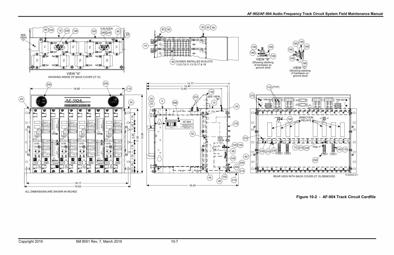
AF-902/AF-904 Audio Frequency Track Circuit System Field Maintenance Manual
Copyright 2019 SM 8051 Rev. 7, March 2019 10-7
T8
T7
T6
VIEW "A"
16.85
SHOWING INSIDE OF BACK COVER (IT.15)
T4T2
T1 T3 T5
CONTROLLER
N12360301
AUXILIARY
N12360401
GUIDES INSTALLED IN SLOTS1,3,5,7,9,11,13,15,17 & 19
SEEVIEW
"C"
18.17
MODE
ESCAPE
UP
DOWN
ENTER
PRESS TORESET
STATUSLEDS
IN RESETWHEN LIT
AUX2
POWER SUPPLYN12360501
DEBUGPORT
AUX 1
19.00
2
ON
DEBUGPORT
OFF
STATUSLEDS
ADJ
PRESS TORESET
MODEUP
DOWN
AUX2
+15V-15V
ENTER
+5V+15V
-15V LEFT
PO
WE
R S
UPP
LY
GND
OFF
DEBUGPORT
STATUSLEDS 2
RIG
HT
PO
WE
R S
UPP
L YLE
FTP
OW
ER
SU
P PLY
11. 5
0
POWER SUPPLYN12360501
MADE IN USA
1
13.9
9
UNION SWITCH & SIGNAL645 RUSSELL ST.
BATESBURG, SC 29006
AF-904
E
UNION SWITCH & SIGNAL
DIR.
2
W
2
16.40
SEEVIEW"C"
ENTER
MODEUP
DOWNAUX 1
AUX2
ESCAPE
IN RESETWHEN LIT
PRESS TORESET
ADJ
WDIR.
W
AUX 1
DIR.
E
UP
DOWN
MODE
AUX2
1
ESCAPE
ENTER
0
ON
0
ESCAPE AUX 1
XMFR
+5V
+15V-15V
XMFR
XMFR
+5V
ON
+15V-15V
+5V
2
ON
+15V
OFF
-15V
0
GND
STATUSLEDS
IN RESETWHEN LIT
0
1
OFF
DEBUGPORT
PRESS TORESET
E
ADJ
GND
-15V+15V
+5V
-15V
+15V+5V
DIR.
+5V
IN RESETWHEN LIT
2 XMFR
ADJ
W
E
-15V
RIG
HT
PO
WE
R S
UPP
LY+15V+5V
GND
1
260
RX4TRK3&4
J21
3 34 4 4J4 4
5
RX2
5
TX1 TRK1&2 J1
T1
TRACK 1TRACK 2SW1
TX3
T4
TRACK 4
5 5
TX2R
X1 4
1 1
R1T2
"PIN 1"
J48
5543
Z
22
J23
PH3
1
RX
3TX45
43
1
J49
R4
2345
R3
1
T3
270
REAR VIEW WITH BACK COVER (IT.15) REMOVED
23
PH1
12341
R2
1J32 2 2 2
OPENTRACK 3
3 3
PH2PH4
(TYP)
J22
115
140
230 235 145
SEE VIEW "B"
4 PLACES
AUXILIARYBOARD
N12360401
CPS ACTIVE
ON-LINE
SELF
PARTNERHEALTH
U-LOK COMM
BLOCK SPEED SET
LEVEL
DATATRACKCLEAR
P1
P2RECEIVER
INPUT
+12V
+5VVITAL
OUTPUTS
BANDPASS FILTER
ANALOG GROUND
+44V
SYSTEM GR OUND
+
-
CPS 500Hz
TRANSMITTE ROUTPUT
AUXILIARYBOARD
N12360401
CPS ACTIVE
ON-LINE
SELF
PARTNERHEALTH
U-LOK COMM
BLOCK SPEED SET
LEVEL
DATATRACKCLEAR
P1
P2RECEIVER
INPUT
+12V
+5VVITAL
OUTPUTS
BANDPASS FILTER
ANALOG GROUND
+44V
SYSTEM GR OUND
+
-
CPS 500Hz
TRANSMITTE ROUTPUT
AUXILIARYBOARD
N12360401
CPS ACTIVE
ON-LINE
SELF
PARTNERHEALTH
U-LOK COMM
BLOCK SPEED SET
LEVEL
DATATRACKCLEAR
P1
P2RECEIVER
INPUT
+12V
+5VVITAL
OUTPUTS
BANDPASS FILTER
ANALOG GROUND
+44V
SYSTEM GR OUND
+
-
CPS 500Hz
TRANSMITTE ROUTPUT
AUXILIARYBOARD
N12360401
CPS ACTIVE
ON-LINE
SELF
PARTNERHEALTH
U-LOK COMM
BLOCK SPEED SET
LEVEL
DATATRACKCLEAR
P1
P2RECEIVER
INPUT
+12V
+5VVITAL
OUTPUTS
BANDPASS FILTER
ANALOG GROUND
+44V
SYSTEM GR OUND
+
-
CPS 500Hz
TRANSMITTE ROUTPUT
.75
1.25
1.75
1.75
2.25
1.25
1.75
DIAGPORT
TRK CKTCTRLR
N123603-01
DIAGPORT
TRK CKTCTRLR
N123603-01
DIAGPORT
TRK CKTCTRLR
N123603-01
DIAGPORT
TRK CKTCTRLR
N123603-01
250
23527575270
170
13.4014.46
14.77
P/N N12200204 S/N 320500278REV 10
28595 105 15 330 180 100 235 90
10
85 80
65
30 85 80
VIEW "B"(Showing stacking
of hardware onground stud)
185
190 195
190
VIEW "C"(Showing stacking
of hardware onground stud)
195
185
190
185195
190
40
240 240
110
35 520
25 998
270
130
1545
50
175
270
135 150
95
60105
200205
210
4590
100215
R122002A R11
ALL DIMENSIONS ARE SHOWN IN INCHES
DIRECTIONRELAYS
Figure 10-2 - AF-904 Track Circuit Cardfile


AF-902/AF-904 Audio Frequency Track Circuit System Field Maintenance Manual
Copyright 2019 SM 8051 Rev. 7, March 2019 10-9
10.4. AF-902 and AF-904 Cardfile PCBs
The AF-902 and AF-904 cardfiles contain the printed circuit boards listed in Table 10-4. The figures associated with this table are Figure 1-3, Figure 1-4, and Figure 1-5.
Table 10-4 - Cardfile PCBs Parts List
ITEM NUMBER DESCRIPTION PART NUMBER 1 Track Circuit Controller PCB N12360301 2 Auxiliary PCB N12360401 3 Power Supply PCB N12360501
10.5. Coupling Units
The coupling units associated with the AF-902 and AF-904 track circuits are listed in Table 10-5.
Table 10-5 - Coupling Units Parts List
ITEM NUMBER DESCRIPTION PART NUMBER
1 Coupling Unit for inductively-coupled locations (“S”, “O”, or “I” bonds) (See Figure 1-6 through Figure 1-8.) N37500601
2 Coupling Unit for “direct injection” locations (e.g., crossovers) (See Figure 1-9.) N37500603
3 Coupling Unit for “cab signaling loop” locations (See Figure 2-4.) N37500604

AF-902/AF-904 Audio Frequency Track Circuit System Field Maintenance Manual
Copyright 2019 SM 8051 Rev. 7, March 2019 10-10

AF-902/AF-904 Audio Frequency Track Circuit System Field Maintenance Manual
Copyright 2019 SM 8051 Rev. 7, March 2019 11-1
11. Technical Support 11.1. RAIL Team and Technical Support
The Rapid Action Information Link (RAIL) team was created in 1996 to serve the technical needs of current and potential STS USA customers. Convenient, 24-hour access and a rapid resolution to customer problems are the trademarks of this organization. The RAIL Team, which is staffed primarily by STS USA product and application engineers, is ready to assist and resolve any technical issues concerning this or any other STS USA product.
Any questions regarding the contents of this service manual should be directed to the RAIL Team by telephone at 1-800-652-7276 or through Internet E-mail at [email protected].

AF-902/AF-904 Audio Frequency Track Circuit System Field Maintenance Manual
Copyright 2019 SM 8051 Rev. 7, March 2019 11-2


(082) Інстытут гісторыі НАН Беларусі працягвае](https://img.pdfslide.us/doc/110x75/5f2793f0286de4127d1d344e/-29compressedpdf-94902904476082-f-.jpg)


![642-902 exam questions - updated 642-902 test questions [Infographic]](https://img.pdfslide.us/doc/110x75/58e7676d1a28ab5b2a8b656f/642-902-exam-questions-updated-642-902-test-questions-infographic.jpg)