Embed Size (px)
Citation preview
AES-EPOSTUPYPROGRAM
FINALSTUDYREPORTVolumeI
_.o,..,c. . L,_,_YCOPY
CFSTI PRICE(S) $ JAN171965
Hard "copy (HC) J" (_ _) MANNEDSPACF..'3BP.FTCENTEB
Microfiche (MF) . ,_'_.,_.__ HousTON, TEXAS
ff 653 July65
___ Federal By=ternsDivision,E|ectronics Systems Centre', Owego, New York
196601171
AES-EPO STUDY PROGRAM
Final Study ReportVolume I
ORIGINATED: AES- EPO Staff
CLASSIFICATION A_ND _ -<-I"?".,v'" /CONTENTS APPROVAL: _'_ t/_--_m_-. • "-_-
/7/.,:,,.PROJECT OFFICE APPROVAl,: _ L -'_= ;",. i_f
i ,("
IBM NUMBER: 65-562-011
CONTRACT NUMBER: NAS 9-4570
Prepared for theMANNED SPACECRAFT CENTER
National Aeronautics and Space AdministrationHouston, Texas
7__ Electronics Syeteme Center, Owego, New York
31 December 1965
1966011714-002
FOREWARD
A computer concepts study was conducted at the IBM Electronics Sys-tems Center at Owego, New York, under IBM Contract NAS 9-4570, for theManned Spacecraft Center, Houston, Texas. The objective of the study wasto investigate possible solutions to long term and time critical reliabilityproblems as they affect the Apollo Command Module guidance and controlcomputer in its application to the AES mission. Volume I of this finalreport presents a summary of the work performed during the study, andVolume II presents detailed technical descriptions of the variousinvestigations.
1966011714-003
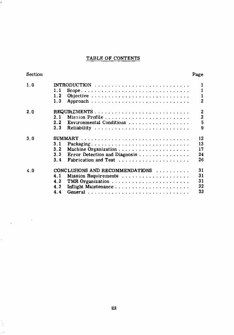
TABLE OF CONTENTS
Section Page
I.0 INTRODUCTION ............................ I
I.I Scope ................................ 1I.2 Objective............................. 1I.3 Approach ............................. 2
2.0 REQUIREMENTS ............................ 22.1 Mission Profile......................... 22.2 Environmental Conditions.................. 5
2.3 Reliability............................ 9
3.0 SUMMARY ................................ 12
3.1 Packaging............................. 133.2 Machine Organization..................... 173.3 Error Detectionand Diagnosis ............... 243.4 Fabricationand Test ..................... 26
4.0 CONCLUSIONS AND RECOMMENDATIONS .......... 31
4.1 Mission Requirements .................... 314.2 TMR Organization....................... 314.3 InflightMaintenance ...................... 324.4 General .............................. 33
iii
1966011714-004
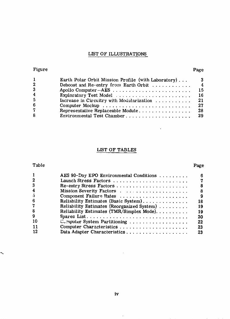
LIST OF ILLUSTRATIONS
Figure Page
1 Earth Polar Orbit Mission Profile (with Laboratory) .... 32 Deboost and Re-entry from Earth Orbit ............ 43 Apollo Computer--AES ........................ 154 Exploratory Test Model ....................... 165 Increase in Circuitry with Modulaxization ........... 216 Computer Mockup ........................... 277 Representative Replaceable Module ................ 288 Environmental Test Chamber .................... 29
LIST OF TABLES
Table Page
1 AES 90-Day EPO Environmental Conditions ......... 62 Launch Stress Factors ....................... 73 Re-entry Stress Factors ...................... 84 Mission Severity Factors .................... 85 Component Failure Rates ..................... 96 Reliability Estimates (Basic System) .............. 187 Reliability Estimates (Reorganized System) ......... 198 Reliability Estimates (TMR/Simplex Mode) .......... 199 Spares List ............................... 2010 C..mputer System Partitioning .................. 2211 Computer Characteristics ..................... 2312 Data Adapter Characteristics ................... 23
iv
1966011714-005
1.0 INTRODUCTION
The study described by this report was performed under contractNAS 9-4570 for the Manned Spacecraft Center, National Aeronauticsand Space Administration, Houston, Texas. Although a specific mis-sion and a specific computer subsystem were used as models for thestudy, the individual investigations were conceptual in nature ratherthan attempts to apply existing equipment or techniques. E:tch conceptwas investigated to the level required to provide a satisfactory degreeof confidence in the feasibility of applying that concept to the specifiedmission.
1.1 Scope
The study consisted of an investigation of the application of theSaturn V computer and a redundant version of the Apollo backup dataadapter as a means of meeting the reliability and mission requirementsof a 90-day Earth Polar Orbit (EPO) Apollo Extension System (AES)mission. P:_ckaging; reliability; fault detection and isolation; inflightmaintenance in high humidaty, zero gravity environments; optimumsparing level; module and channel switching; and other pertinent itemswere studied in an attempt to determine the required redesign of thesubject computer and data adapter subsystem to enable it to meet theguidance and control functional requirements and reliability apportion-ment of a typical 90-day AES-EPOmission. Limited fabricationdemonstrating an approach to sparing in a high humidity, zero gravityenvironment was also required.
1.2 Objective
The objective of this study was to investigate possible solutionsto long-term and time-critical reliability problems as they affect theApollo Command Module guidance and control computer and its ap-plications to AES missions. Specifically, the Saturn V Triple ModularRedundant (TMR) computer and a redundant version of the Apollobackup data adapter were investigated as a means of solving the timecritical reliability problem° A detailed investigation of in/light maiii-tenance or module and channel switching of the computer and dataadapter were investigated as a means of solving the long term reli-ability problem.
1966011714-006
1.3 Approach
The Saturn V computer and a redundant version of the Apollobackup data adapter were examined to determine how their packaging,reliability and machine organization could be improved to meet therequirements of extended Apollo missions. Several concepts and aNternate techniques were investigated as solutions for each of the "prob-lem areas" uncovered by examination of this basic computer system.A reconfigured subsystem was derived by selecting the best solutionfor each problem area.
2.0 REQUIREMENTS
The investigation performed under this coutract was directedtoward making the subject computer and data adapter subsystemcapable of meeting AES requirements. The principle inputs weremission profile, reliability apportionment, and Block II ApoI_o Guid-ance and Control Computer requirements. To avoid duplication ofeffort between this study and contract NAS 9-3724 (Apollo BackupStudy), a rigorous verification that the AES configuration will meetthe Block II Apollo functional requirements was deferred to the backupcomputer study. Care was taken, however, to assure that the mem-ory capacity of the AES computer was sufficient for the mission andthat the computation speed was faster than the Block II Apollo cow-puter.
2.1 Mission Profile
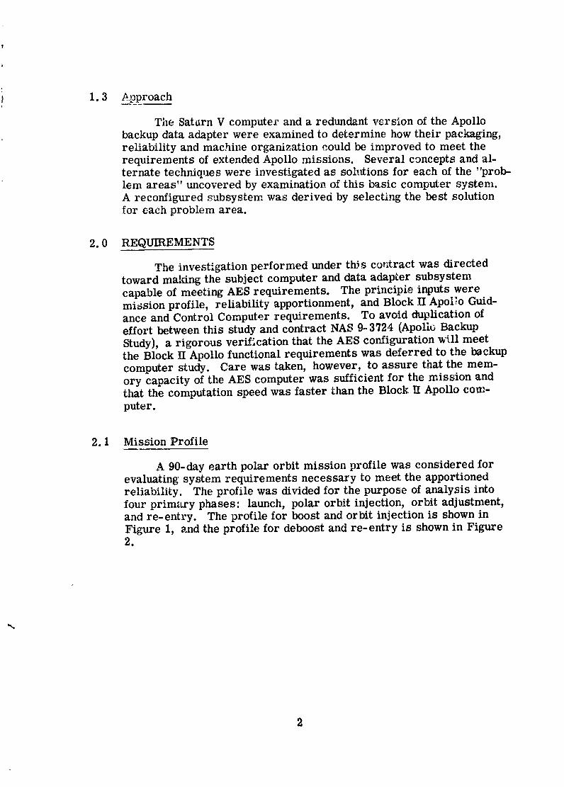
A 90-day earth polar orbit mission profile was considered forevaluating system requirements necessary to meet the apportionedreliability. The profile was divided for the purpose of analysis intofour prim_wy phases: launch, polar orbit injection, orbit adjustment,and re-entry. The profile for boost and orbit injection is shown inFigure 1, and the profile for deboost and re-entry is shown in Figure2.
1966011714-007
The primary function of the AES computer dur_mg boost is tomonitor the guidance and control of the Saturn vehicle. Guidanceduring the entire S-IC stage burn period is in accordance with a pre-deterL_ined time-tilt program. An iterative guidance mode (pathadaptive guidance) is used for the S-If and S-IVB powered flight phases.Cutoff of the S-IC and S-If stages occurs when the fuel is depleted to apredetermined level, while cutoff of the S-IVB occurs when the veloc-ity for orbital injection is attained, The functions which must bemonitored _nd the parameters which must be computed by the AESsubsystem during boost include:
1) Navigation monitoring--determine velocity vector, per-form coordinate transfer, calculate present position,project gravity vector, generate a gyro drift correction,and determine vehicle attitude;
Coast, Transpose,j_ 200-nmi PolarOrbitand Dock-
SM LightS-IVB Shutdown t = 66 rnint = 640 sec Burnt_rne140 sec
S-II Burnout S-IVBt = 543 sec lO0-nmi ReJight
Parking Burntime392 secOrbit
LESJettisont = 174 sec
_-IC Burnoutt = 150 sec
SaturnV Launcht=O
Figure 1. Earth Polar Orbit Mission Profile (with Laboratory)
3
1966011714-008
2) Guidance monitoring--compute steering commands,required velocity, engine cutoff times;
3) Control monitoring-engine ignition, engine cutoff,ullage rocket fire, stage jettison;
4) Telemetry transmission of monitored data.
The time periods for the three phases of boost are:
1) S-IC burn- 0.042 hours,
2) S-II burn-- 0. 110 hours,
3) S-IV2 burn- 0. 027 hours,
4) Total (from SOW)-- 0o 2fi0 hours
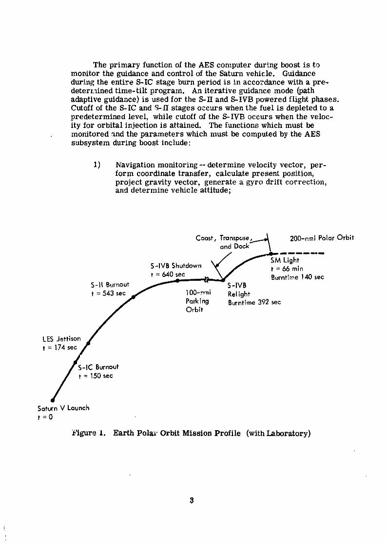
SeparateFrom SM Light
200-nmi Orbit Laboratory Burntlme 18 sec
= mm CM/f, "V,,q::.paration
._1_ :--400,000 ft
\\t=6
3-__ h = 40,000 ft
Parachute
_. Deployment
Figure 2. Deboost and Re-entry from Earth Orbit
r
4
1966011714-009
Th¢ primary function of the AES computer during orbit injection(transfer from 100-mile parking orbit to 200-mile EPO) is also tomonitor the guidance and control of the vehicle. The AES compute_:must be capable of providing backup guidar.ce and control with aninjection accuracy of 10 nautical miles (one sigma). The time periodsfor orbital injection and docking are:
1) S-IVB burn --0. 110 hours,
?_ SM burn -- 6. 040 hours.
The AES computer subsystem is required to control vehicleattitude during orbital operations. The required attitude deadband is+0.50 degrees (all axes) and the allowable drift rates are ±0. 02 de-grees per second (about zero for two axes and about the orbital ratefor the third axis). Powered phases for orbit maintenance are notconsidered critical for the purposes of this ,_tudy.
Guidance and control of the command module (CM) and servicemodule (SM) are required of the AES computer suL :ystem during re-entry. This function was examined in detail under contract N2_S9-3724 (the Apollo Backup Study) and the results were factored intoTask C (machine organization tradeoffs). The event sequence for re-entry from the contract statement of work is:
Time (rnin) Event
0 Start re-entry preparations
55. 0 Service mod_e ignition
55.3 Service module shutdown
69. 0 CM/SM separation
77. 0 h = 400, 000 feet
83-90 Parachute deployment (h = 40, 000 feet).
2.2 Environmental Conditions
The environmental requirements for Apollo as defined inspecification ND 1002037 were considered valid for AES missions.
5
1966011714-010
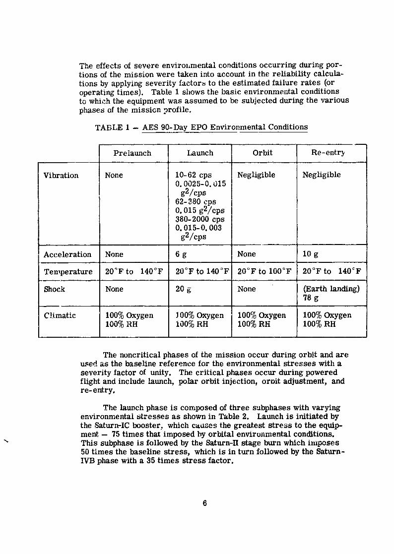
The effects of severe envirohmental conditions occurring during por-tions of the mission were taken into account in the reliability calcula-tions by applying severity factor_ to the estimated failure rates (oroperating times). Table l shows the basic environmental conditionsto which the equipment was assumed to be subjected during the variousphases of the missiGn profile,
TABLE 1 -- AES 90-Day EPO Environmental Conditions
Prelaunch Launch Orbit Re-entry
Vibration None 10-62 cps Negligible Negligible0. 0025-0. 015
g2/cps62- 380 cps I0. 015 g2/cps I380-2000 cps0. 015-0. 003
g2/cps
Acceleration None 6 g None I0 g
Temperature 20°F to 140°F 20°F to 140°F 20°F to 100°F 20°F to 140OF
Shock None 20 g None (Earthlanding)78 g
Climatic 100% Oxygen J00% Oxygen 100% Oxygen 100% Oxygen100% RH 100% RH 100% RH 100% RH
The noncritical phases of the mission occur during orbit and axeused as the baseline reference for the environmental stresses with a
severity factor of unity. The critical phases occur during poweredflight and include launch, polar orbit injection, oruit adjustment, andre-entry.
The latmch phase is composed of three subphases with varyingenvironmentai stresses as shown in Table 2. Launch is initiated bythe Saturn-IC booster, which causes the greatest stress to the equip-merit - 75 times that imposed by orbital envirunmental conditions.
" This subphase is followed by the Saturn-II stage burn which imposes50 times the baseline stress, which is in turn followed by the Saturn-!V_Bphase with a 35 times stress factor.
6
1966011714-011
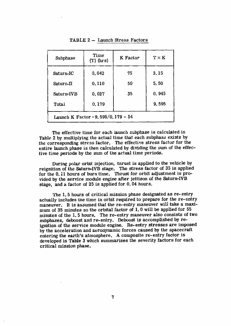
TABLE 2 -- Launch Stress Factors
, L
TimeSubphase (T) (hrs) K Factor T × K
Saturn-IC 9. 042 75 3.15
Saturn-II 0. Ii0 50 5.50
Saturn-IVB 0.027 35 0. 945
Total 0. 179 9. 595l
Launch K Factor =9. 595/0. 179 = 54
The effective time for each launch subphase is calculated inTable 2 by multiplying the actual time that each subphase exists bythe corresponding stress factor. The effective stress factor for theentire launch phase is then calculated by dividing the sum of the effec-tive time periods by the sum of the actual time periods.
During polar orbit injection, thrust is applied to the vehicle byreignition of the Saturn-IYB stage. The stress factor of 35 is appliedfor the 0. 11 hours of burn time. Thrust for orbit adjustment is pro-vided by the service module engine after jettison of the Saturn-IVBstage, and a factor of 25 is applied for 0.04 hours.
The 1.5 hours of critical mission phase designated as re-entryactually includes the time in orbit required to prepare for the re-entrymaneuver. It is assumed that the re-entry maneuver will take a maxi-mum of 35 minutes so the orbital factor of 1.0 will be applied for 55minutes of the 1.5 hours. The re-entry maneuver also consists of twosubphases, deboost and re-entry. Deboost is accomplished by re-ignition of the service module engine. Re-entry stresses are imposedby the acceleration and aerodynamic forces caused by the spacecraftentering the earth's atmosphere. A composite re-entry factor isdeveloped in Table 3 which summarizes the severity factors for eachcritical mission phase.
7
1966011714-012
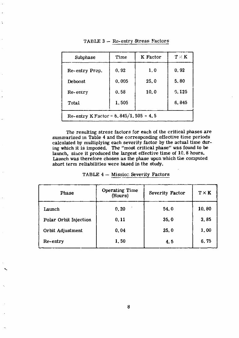
TABLE 3 -- Re-entry Stress Factors
I
Subphase Time K Factor [ T >:K.L -, t
Re-entry Prep. 0.92 1.0 0.92
Deboost 0.005 25.0 5.80
Re-entry 0.58 10.0 0.125
Total 1.505 6.845
. i o
Re-entry K Factor= 6.845/1.505 = 4.5
The resulting stress factors for each of the critical phases aresummarized zn Table 4 and the corresponding effective time periodscalculated by multiplying each severity factor by the actual time dur-ing which it is imposed. The "most critical phase" was found to belaunch, si,,ce it produced the largest effective time of 10.8 hours.Launch was therefore chosen as the phase upon which the computedshort term reliabilities were based in the study.
TABLE 4- Missio: Severity Factors
r , | •
Phase Operating Time(Hours) Severity Factor T x K
Launch 0.20 54.0 I0.80
Polar OrbitInjection 0.11 35.0 3.85
OrbitAdjustment 0.04 25.0 ].00
Re-entry 1.50 4.5 6.75L. | .
8
1966011714-013
2.3 Reliability
Reliability calculations were made on the basis of the missionprofile described in Section 2.1. All charnels of the computer anddata adapter were required to be operative prior to any critical mis-sion phase, since repair was not aUowed during these periods. Re-pair was allowed, however, during noncritical mission _hases.
Reliability calculations were based on duty cycl: s of 25, 50, and100 i_ercent of the noncritical phase time combined with the 1.85 hoursof the critical phase ti:ne. Reliability was calculated on the "o_,,,,,.__ -'_,,.both a zero failure tale as well as a non-zero failure rate for compo-nent electrical cff-time. The system required to meet the apportionedreliability was the syst._,m based on zero failure rate for off-time.
The apportioned computer-data adapter reliability w_s specifiedas 0. 9994 for the missY.on and 0. 999999 for the critical phases. Areliability of ur.ity w_s assumed for the Apollo display and keyboard.
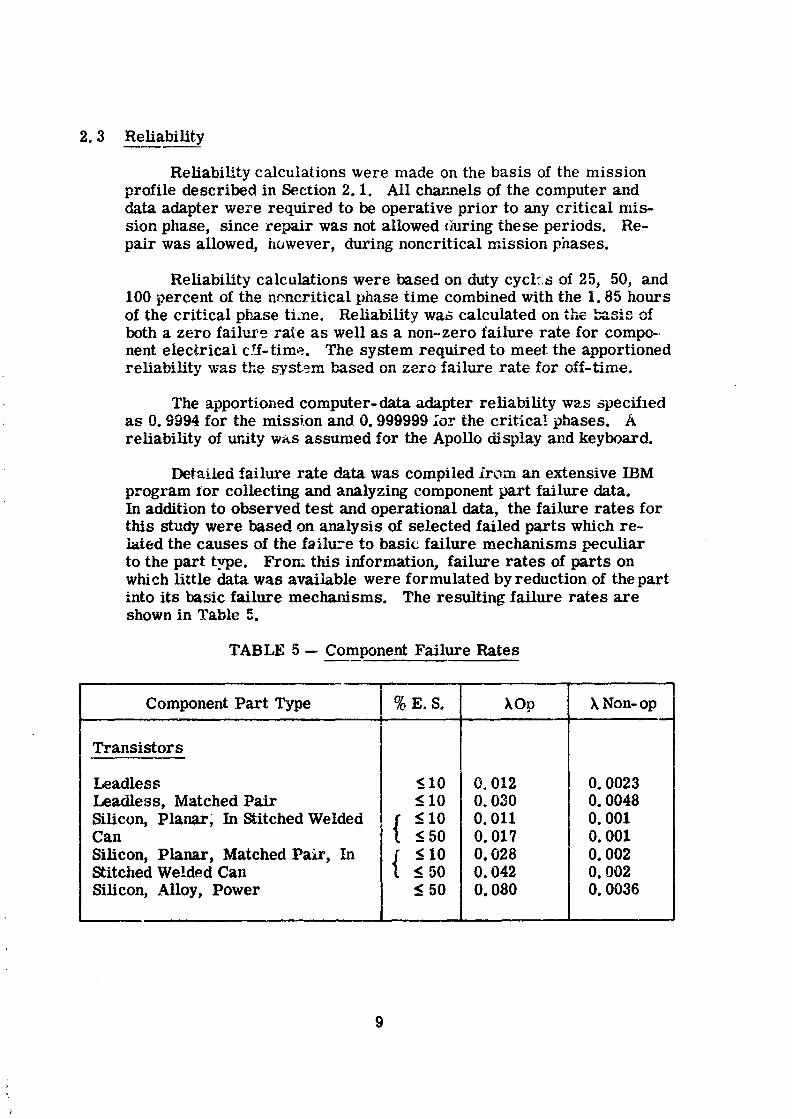
Detai.led failure rate data was compiled irom an extensive IBMprogram ior collecting and analyzing component part failure data.In addition to observed test and operational data, the failure rates forthis study were based on analysis of selected failed parts which re-bred the causes of the failu.-e to basic failure mechanisms peculiarto the part type. From this information, failure rates of parts onwhich little data was available were formulated by reduction of the partinto its basic failure mechanisms. The resulting failure rates axeshown in Table 5.
TABLE 5 -- Component Failure Rates
Component Part Type % E.S. kOp ),Non-opI -- I
Transistors
Leadless <_10 0,012 0.0023Leadless,Matched Pair <_10 0.030 0.0048
Silicon,Planar, InStitchedWelded ! f < 10 0.011 0.001Can I < 50 0.017 0.001
Silicon,Planar, Matched Pair, In j" _<.10 0.028 0.002StitchedWelded Can [ <_.50 0.042 0.002
Silicon,Alloy,Power _<50 0.080 0.0036
1966011714-014
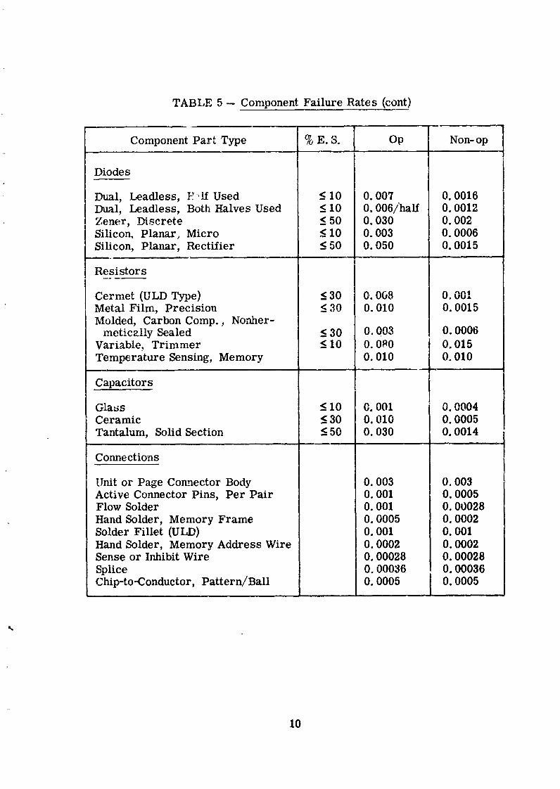
TABLE 5 --Component FailureRates (cont)
Component Part Type % E.S. Op Non-op
Diodes
Dual, Leadless, }:_lf Used _<10 0. 007 0. 0016Dual, Leadless, Both Halves Used <_I0 0.006/half 0. 0012Zener, Discrete _<50 0. 030 0. 002Silicon, Planar_ Micro _<10 0. 003 0.0006Silicon, Planar, Rectifier _<50 0. 050 0. 0015
Resistors
Cermet (ULD Type) <_.30 0. 068 0.001Metal Film, Precision <_30 0. 010 0. 0015Molded, Carbon Comp., Nonher-
metically Sealed _<30 0.003 0.0006Variable, Trimmer _ 10 0.0_0 0. 015Temperature Sensing, Memory 0. 010 0. 010
,, _,,
Capacitorsi
Glass _<10 C. 001 0. 0004Ceramic < 30 0. 010 0. 0005Tantalum, Solid Section <_.50 0.030 0. 0014
Connections
Unitor Page Comnector Body 0.003 0.003Active ConnectorPins, Per Pair 0.001 0.0005Flow Solder 0.001 0.00028
Hand Solder,Memory Frame 0.0005 0.0002SolderFillet(ULD) 0.001 0.001Hand Solder,Memory Address Wire 0.0002 0.0002Sense or InhibitWire 0.00028 0.00028
Splice 0.00036 0.00036Chip-to-Conductor, Pattern/Ball 0.0005 0.0005
10
1966011714-015
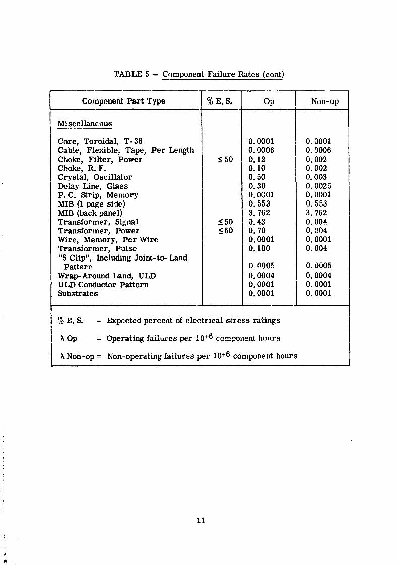
TABLE 5 -- Cnmponent FailureRates (cont)
Component Part Type % E.S. Op Non-opi
Miscellancous
Core, Toroidal,T-38 0.0001 0.0001Cable, Flexible,Tape, Per Length 0.0006 0.0006Choke, Filter,Power < 50 0.12 0.002Choke, R.F. 0.10 0.002Crystal,Oscillator 0.50 0.003Delay Line, Glass 0.30 0.0025P.C. Strip,Memory 0.0001 0.0001MIB (1page side) 0.553 0.553MIB (backpanel) 3.762 3.762Transformer, Signal < 50 0.43 0.004Transformer, Power <_.50 0.70 0.004Wire, Memory, Per Wire 0.0001 0.0001Transformer, Pulse 0.100 0.004"S Clip",IncludingJoint-to-LandPattera 0.0005 0.0005
Wrap-Around I._tnd,ULD 0.0004 0.0004ULD Conductor Pattern 0.0001 0.0001Substrates 0.0001 0.0001
% E.S. = Expected percentofelectricalstressratings
k Op = Operatingfailuresper 10+6 component hours
Non-op = Non-operatingfailuresper 10+6 component hours
11
4
1966011714-016
3.0 SUMMARY
The _Cudy was divided into four primary areas of investigat-gn:
1) packaging, 2) machine organization, 3) error detection and diag_nesis, and 4) fabrication and test. The packaging study was aimedprimarily at deriving packaging techniques applicable to operation and
t maintenance in the high humidity, zero gravity AES environment. Theprincipal goals of the machine organization study were attainment ofthe extremely high reliability requirement of the AES critical phasesand realization of automatic error detection and diagnosJ s. Error
__ detection and diagnosis studies using the Saturn V Syster_ Simulatorprovided insight to the mechanisms of error propagation in a digital
t system and produced the data necessary for the machine organization
effort. The fabrication and test effort included fabrication of a com-puter/data adapter mockup, fabrication of representative module pack-ages and a special environmental chamber in which to test them, ex-
I ploratory tests to determine a satisfactory connector-sealing technique,and evaluation tests of the representative modules.
i In general, all phases of the study were successful. A packagingapproach was derived which is suitable for operation and maintenancein the adverse AES environment. The reliability requirement of0. 999999 for the critical phases of the AES mission was met by the
TMR machine organization which evolved during the study. The re-liability requirement of 0. 9994 for the 90-day mission was met eitherby sparing or by automatic repartitioning of the computer system in
i flight. Automatic error detection was proved by simulation to bel feasible with an efficiency of better than 99 percent without interrupting
normal machine operation (without special test programs or routines).
i Automatic fault isolation to a replaceable module level was achievedby built-in circuits. A logic circuit was designed which not only pro-vides the voting, error detection, and fault isolation functions, but
automatically switches out the failed component.
No extensive tradeoffs were required or performed during thestudy. For example, no other forms of redundancy other than triple
modutar redundancy or variations such as quad redundancy were con-: sidered. Similarly, no tradeoffs were made between built-in testcircuitry and test programming. As a result, the selected conf_gura-
i tion probably is not optimum for the application although it does meetall the requirements specified by NASA-MSC or otherwise known toIBM.
I"
i 12
1966011714-017
The extremely high reliabilities specified for the AES-EPOmission are reasonable in that they can be met by conventional TMRorganization, simple packaging techniques, and existing diagnosticmethods. Further investigations would be required to determinewhether the automatic repair techniques developed during the studywould be worth the cost of the additioJml eqmpment complexity whencompared to manual module replacement.
3.1 Packaging
Several approaches were investigated for packaging the com-puter and data adapter for operation and maintenance in the highhumidity, zero gravity AES environment. A decision was made earlyin the study to package the computer and data adapter in a single unitin order to simplify the interconnection problems. Although thisdecision affects the overall form factor and size of the computer sys-tem, it does not affect the relative merits of the various approachesconsidered or the conclusions of the packaging studies.
The first approach was the conventional packaging technique foraerospace computers in which the computer system is sealed as amalt. Upon removing the unit cover to replace a failed module, theentire interior of the unit is exposed to the spacecraft environment.When the cover is replaced after repair, the free moisture and con-
; taminants trapped in the unit must be purged and the unit repressurizedto somewhat greater than cabin pressure with dry gas.
In the second and third approaches an attempt was made tolimit the degree of exposure during a maintenance action by sealingvarious portions of the computer independently. Since a TMR com-puter consists of essentially three individual computers, each channelcan be sealed individually so that only a third of the computer is ex-posed each time a repair is attempted. In the Saturn V computer, thecasting is designed such that each logic channel is partitioned intoeffectively five physical cells. If each cell is separately sealed, thena fifteenth or less of the computer is exposed each time a repair is
: attempted.
In each case the covers woulcl be sealed by means of modified0-rings and the exposed volume purged and repressurized with dry
: gas to an overpressure of two or three psi. Gasket-sealed units have: been designed at IBM to provide leakage rates as low as 10-7 cubic_ centimeters per second per inch of linear seal length.
;._
_ 13
1966011714-018
Tr_deoffs between the three sealing approaches were made onthe basis of leakage rates, expected repair intervals, module re-placeability, and design complexity. Although each method possessed
, certain advantages ever the other two, the cell-sealing approach wasselected primarily because it provided minimum circuit exposure overthe 90-day mission and because it provided easiest access to a failedmodule, but at a cost in size, weight, and probably cost of fabrication.
Closed loop systems were considered but not emphasized in thestudy. A pressurized system which circulates dehumidified airthrough the computer and contains filters for chemical contaminantshas, at least, history in aircraft applications. The use of freon in aclosed loop or even static system offers several advantages includingmoisture-repellent characteristics.
No matter what packaging approach is selected for applicationin an adverse environment, the problem of sealing the connectorsremains a problem. Although the connectors associated with thepluggable mod.Aes are partially protected in any of the approachesdescribed above, the cable connectors which connect the computersystem with other systems remain exposed to the spacecraft environ-ment. Study emphasis was therefore given to connector sealing tech-nique s.
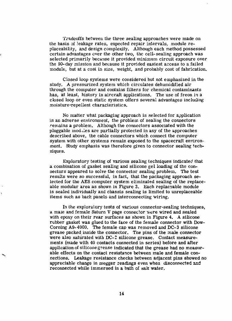
Exploratory testing of various sealing techniques indicated thata combination of gasket sealing and silicone gel loading of the con-nectors appeared to solve the com_ector sealing problem. The testresults were so successful, in fact, that the packaging approach se-lected for the AES computer system eliminated sealing of the replace-able modular area as shown in Figure 3. Each replaceable moduleis sealed individually and chassis sealing is limited to unreplaceableitems such as back panels and interconnecting wiring.
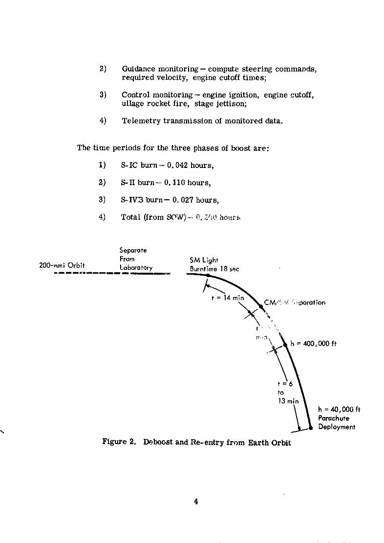
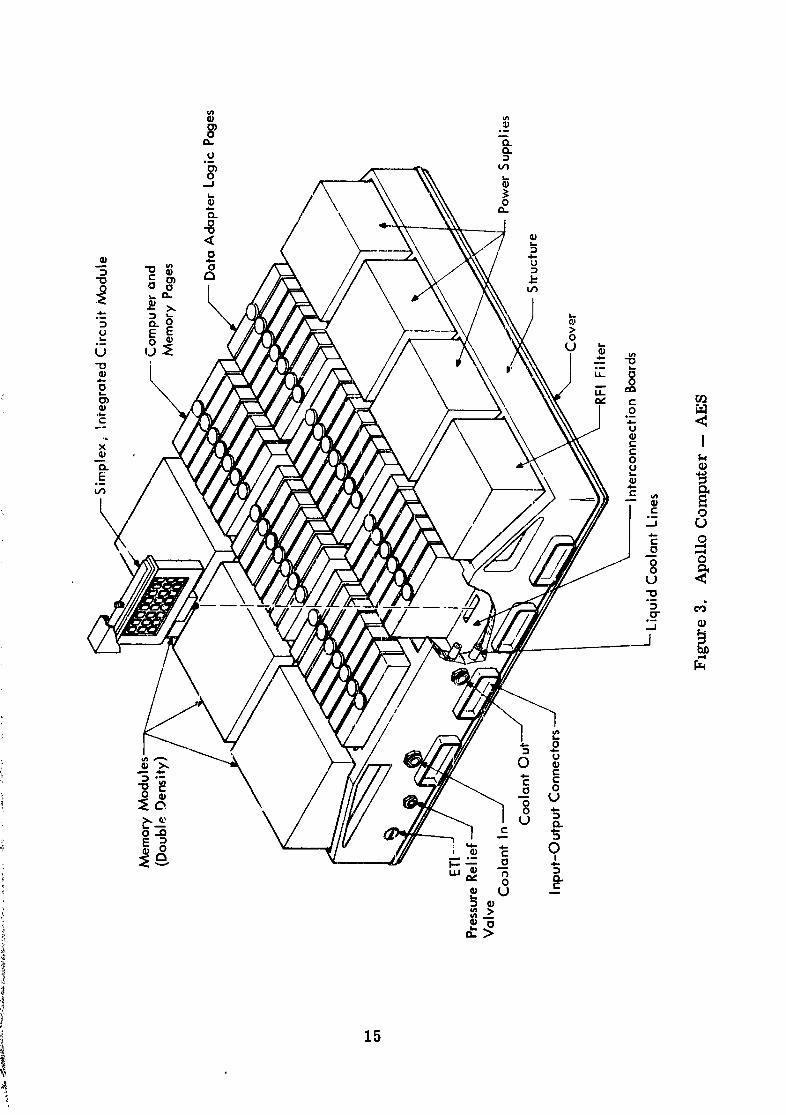
In the exploratory tests of various cormector-sealing techniques,a male and female Saturn V page connector were wired and sealedwith epoxy on their rear surfaces as shown in Figure 4. A siliconerubber gasket was glued to the face of the female connector with Dow-Corning Ag-4000. The female cap was removed and DC-3 siliconegrease packed inside the connector. The pins of the male connectorwere also saturated with DC-2 silicone grease. Contact measure-ments (made with 40 contacts connected in series) before and afterapplication of silicone grease indicated that the grease had no measur-able effects on the contact resistance between male and female con-
"_ nections. Leakage resistance checks between adjacent pins showed noappreciable change in megger readings even when disconnected o.-_.dreconnected while immersed in a bath of sait water.
14
1966011714-019
_oxy
Gonnector
Gasket
Screws
Cap Gasket
Conncctor
Epoxy
'Cable
Figure 4. Exploratory Test Model
16
1966011714-021
Although individual sealing of the replaceable modu:es and applica-tion of the above connector-seahng technique would seem to solve thepackaging problem for operation and maintenance in the adverse AF3environment, a detailed data analysis of test results on contact materi-als was performed to assure that the properties of the contact materialswouL' not present a problem in the AES application. This analysis re-sulted in the recommendation of gold-on-nickle as the contact material,as in the Saturn V connectors, but with the thickness of the gold platit,_increased from about 50 mils to 200 mils. If the increased platingthickness and stringent quality control methods prove to be inadequatein controlling plating porosity, a technique for welding gold foil on basecontact materials has been proven feasible at IBM but not as yet usedbecause of the higher fabricaL_on costs involved. Although the recom-mended process will result in expensive connectors, their performancein the adverse AES environment seems assured and worth the cost.
3.2 MachineOrganization
The Saturn" computer and a redundant version of the Apollobackup data adaptt," were used as a basic system for the machine or-ganization studies. This basic computer system was analyzed fur itsreliability, error detection, failure isolation, and performance capa-bilities and changes to the machine organization made to improve theweak areas uncovered by the analysis.
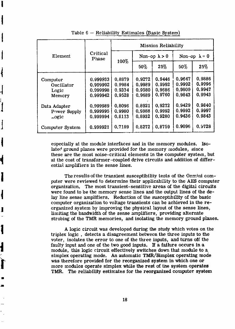
Simulation oi _,te reliability model for the basic .3ystem revealedtha* neither the time critical nor long term reliabilities were met by thebasic system without sparing, as indicated in Table 6. In order to im-Frove system reliability (especially in the critical mission phases), thesimplex computer oscillator and tim duplex memories and the duplexpov,er supplies were triplicated. A novel oscillator configuration wasdesigned in which three unsynchronized oscillators operate in paralleland are selectively gated into the system according to error detectorindications. TMR memories provide a reliability increase by forcingerror-causing disagreements from the word level of the duplex con-figura'_mn to the bit level of TMR voting. Triplex power supplies withoverlapping duplex distribution nets were selected as the power systemfor the reorganized computer system.
Two machine organization areas which were investigated with thepurpose of improving system reliability but which were not factoredinto the reliability computations were grounding and transiec _,protec-tion. The grounding scheme of the Satuln V system was retained ingeneral but revised in detail to reduce interaction of ground _urrents,
17
1966011714-022
I
I Table 6 -- Reliability Estimates (Basic System)Mission Reliability
1 'Element Critical Non-op k > 0 Non-op k = 0Phase 100% .....
j 50% 25% 50% 25%I
Computer 0.999933 0.8879 0.9272 0.9446 0.9647 0.9886Oscillator 0.999992 0.9984 0.9989 0.9992 0.9992 0.9996|
•l Logic 0.999998 0.9334 0.9580 0.96860. 9809 0. 9947
Memory 0.999942 0.9528 0.9689 0.9760 0.9843 0.9943i] Data Adapter 0.999989 0.8096 0.8921 0.9272 0.9429 0.98404 P_wer Supply 0.999995 0.9980 0.9988 0.9992 0.9992 0.9997
._ogic ! 0.999994 0.8113 0.8932 0.9280 0.9436 0.9843
J Computer System 0.999921 0.7189 0.8272 0.8759 0.9096 0.9728
especially at the module interfaces and in the memory modules. Iso-lated ground planes were provided for the memory modules, sincethese are the most noise-critical elements in the computer system, but
at the cost of transformer-coupled drive circuits and additionof differ-
ential amplifiers in the sense lines.
The results of the transient susceptibility tests of the C_mlni com-puter were reviewed to determine their applicability to the AES computerorganization. The most transient-sensitive areas of the digital circuits
were found to be the memory sense lines and the output lines of the de-lay line sense amplifiers. Reduction of the susceptibility of the basiccomputer organization to voltage transients can be achieved in the re-
] organized system by improving the physical layout of the sense lines,limiting the bandwidth of the sense amplifiers, providing alternatestrobing of the TMR memories, and isolating the memory ground planes.
_I A logiccircuitwas developedduringthe studywhich votes on theI
triplexlogic, detectsa disagreementbetween the three inputstothevoter,isolatesthe error toone ofthethree inputs,and turns offthe
t faulty input and one of the two good inputs. If a failure occurs in amodule, this logic circuit effectively switches down that module to a.simplex operating mode. An automatic TMR/Simplex operating mode
was therefore provided for the reorganized system in which one ormore modules operate simplex while the rest of the system operatesTMR. The reliability estimates for the reorganized computer system
"1
,Jm
18
1966011714-023
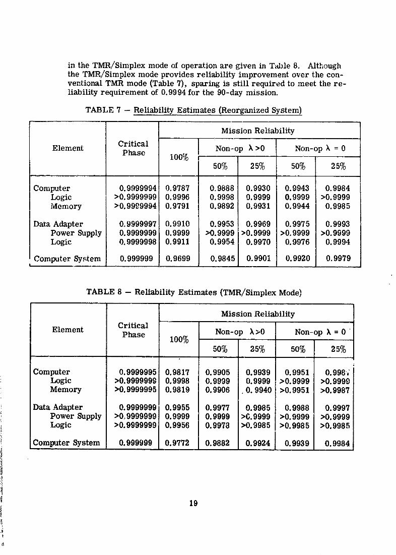
in the TMR/Simplex mode of operation are given in Table 8. Althoughthe TMR/Simplex mode provides reliability improvement over the con-ventional TMR mode (Table 7), sparing is still required to meet the re-liability requirement of 0.9994 for the 90-day mission.
TABLE 7 -- Reliability Estimates (Reorganized System)
Mission Reliability
Element Critical Non-op ), >0 Non-op k = 0Phase 100%
50% 25% 50% 25%
Computer 0.9999994 0.9787 0.9888 0.9930 0.9943 0.9984Logic >0.9999999 0.9996 0.9998 0.9999 0.9999 >0.9999Memory >0.9999994 0.9791 0.9892 0.9931 0.9944 0.9985
Data Adapter 0°9999997 0.9910 0.9953 0.9969 0.9975 0.9993Power Supply 0.9999999 0.9999 >0.9999 >0.9999 >0.9999 >0.9999Logic 0.9999998 0.9911 0.9954 0.9970 0.9976 0.999,t
Computer System 0.999999 0.9699 0.9845 0.9901 0.9920 0.9979!
TABLE 8 --ReliabilityEstimates (TMR/Simplex Mode)
Mission Reliability
Element Critical Non-op ),>0 Non-op ]k= 0 "Phase 100%
50% 25% 50% 25%
Computer 0.9999995 0.9817 0.9905 0.9939 0.9951 0.998;Logic >0.9999999 0.9998 0.9999 0.9999 >0.9999 >0.9999Memory >0.9999995 0.9819 0.9906 0. 9940 >0.9951 >0.9987
Data Adapter 0.9999999 0.9955 0.9977 0.9985 0.9988 0.9997Power Supply >0o9999999 0.9999 0.9999 >0.9999 >0.9999 >0.9999Logic >0.9999999 0.9956 0.9978 >0.9985 >0.9985 >0.9985
Computer System 0. 999999 0.9772 0.9882 0.9924 0.9939 0.9984
19
A#.
1966011714-024
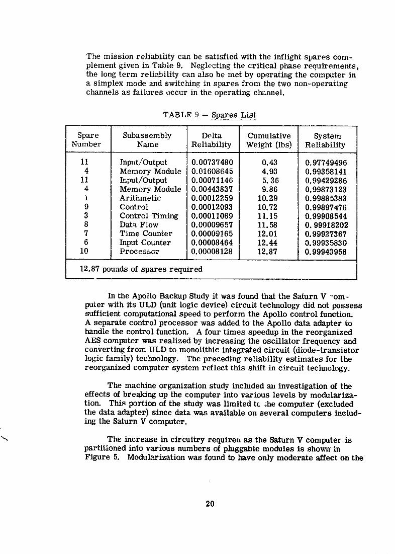
The mission reliability can be satisfied with the irfflight spares com-plement given in Table 9. Neglecting" the critical phase requirements,the long term reliability can also be met by operating the computer ina simplex mode and switching in spares from the two non-operatingchannels as failures occur in the operating channel.
TABLE 9 -- Spares List
Spare Subassembly Delta Cumulative SystemNumber Name Reliability Weight (lbs) Reliability
11 Input/Output 0.00737480 0.43 0.977494964 Memory Module 0.01608645 4.93 0.99358141
ll Input/Output 0.00071146 5. 36 0.994292864 Memory Module 0.00443837 9.86 0.99873123i Arithmetic 0.00012259 10.29 0.998853839 Control 0.00012093 10.72 0.99897,t763 Control Timing 0.00011069 11.15 0.999085448 Dat_ Flow 0.00009657 II. 58 0. 999182027 Time Counter 0.00009165 12.01 0.999273676 Input Counter 0.00008464 12.44 0.99935830
10 Processor 0.00008128 12.87 0.99943958
12.87 pounds of spares required
In the Apollo Backup Study it was found that the Saturn V _om-puter with its ULD (unit logic device) circuit technology did not possesssufficient computational speed to perform the Apollo control function.A separate control processor was added to the Apollo data adapter tohandle the control function. A four times speedup in the reorganizedAES computer was realized by increasing the oscillator frequency andconverting from ULD to monolithic integrated circuit (diode-transistorlogic family) technology. The preceding reliability estimates for thereorganized computer system reflect this shift in circuit technology.
The machine organization study included an investigation of theeffects of breaking up the computer into various levels by modulariza-tion. This portion of the study was limited tc _he computer (excludedthe data adapter) since data was available on several computers includ-ing the Sar,,rn V computer.
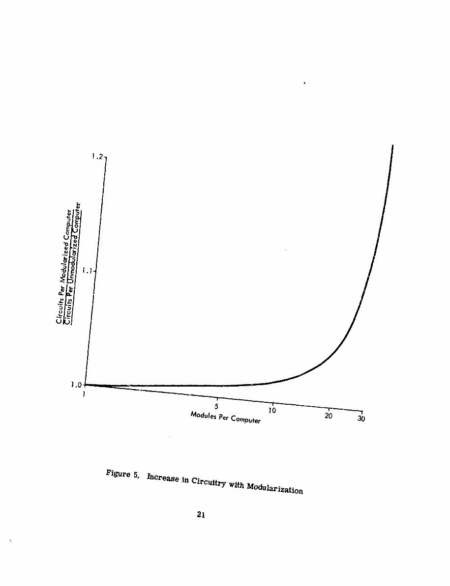
"_ The increase in circuitry require_ as the Saturn V computer ispartitioned into various numbers of pluggable modules is shown inFigure 5. Modul3rization was found to have only moderate affect on the
2O
1966011714-025
1.0I
5 10
ModulesPerCompufer 20 30
Figure 5. Increase ,in Circuitry With Modu/arization
21
1966011714-026
total amount of circuitry required by the computer organization in therange from an unmodularized unit to about ten modules. As the com-puter is partitioned into modules greater than ten, however, the re-quired circuitry increases very rapidly (primarily because this lower-level partitioning cuts across functional areas). The Saturn V computerwas organized into seven functional areas but partitioned into more thanten pluggable modules per channel. The reorganized AES computer waspartitioned into four pluggable modules per channel
The functional relationship between the total intermodule connec-tions per circuit as the partitioning is carried to lower levels resultsin a similarly shaped curve with the break point at about ten modules.The same general relationship exists between modularization and thetotal number of voters required per machine. Although the AES com-puter was partitioned into four modules primarily to optimize the fail-ure isolation capabilities of the built-in detection circuitry, this mod-ularization level is well within the cost constraints of total circuits,intermodule connections, and total number of voters required.
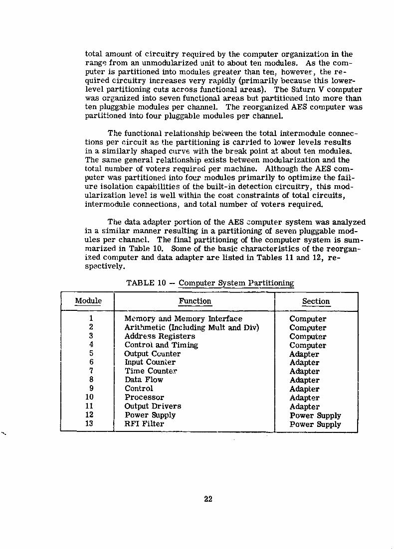
The data adapter portion of the AES computer system was analyzedin a similar manner resulting in a partitioning of seven pluggable mod-ules per channel. The final partitioning of the computer system is sum-marized in Table 10. Some of the basic characteristics of the reorgan-ized computer and data adapter are listed in Tables 11 and 12, re-spectively.
TABLE 10 -- Computer System Partitioning
IModule Function [ SectionE
1 Memory and Memory Interface Computer2 Arit.hmetic (Including Mult and Div) Computer3 Address Registers Computer4 Control and Timing Computer5 Output Counter Adapter6 Input Counter Adapter7 Time Counter Adapter8 Data Flow Adapter9 Control Adapter
10 Processor Adapter11 Output Drivers Adapter12 Power Supply Power Supply13 RFI Filter Power Supply
22
1966011714-027
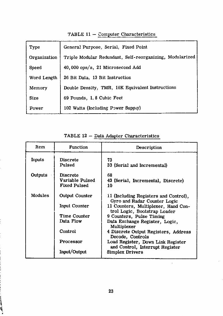
TABLE 11 --Computer Characteristics
Type General Purpose, Serial,Fixed Point
Organization TripleModular Redundant, Self-reorganizing,Modularized
Speed 40,000 ops/s, 21 Microsecond Add
Word Length 26 BitData, 13 BitInstruction
Memory Double Density,TMR, 16K EquivalentInstructions
Size 69 Pounds, 1.8 Cubic Feet
Power 102 WaRs (IncludingPower SuppLy)
TABLE 12 --Data Adapter Characteristics
Item Function Description!
Inputs Discrete 73
Pulsed 33 (Serialand Incremental)
Outputs Discrete 68
Variable Pulsed 43 (Serial, Incremental, Discrete)Fixed Pulsed 10
Modules Output Counter II (IncludingRegistersand Control),Gyro and Radar Counter Logic
InputCounter 11 Counters, MuRiplexer, Hand Con-trolLogic, BootstrapLoader
Time Counter 9 Counters, Pulse TimingData Flow Data Exchange Register,Logic,
MuRiplexerControl 4 DiscreteOutputRegisters,Address
Decode, ControlsProcessor Load Register,Down Link Register
and Control,InterruptRegisterInput/Output Simplex Drivers
23
1966011714-028
3.3 Error Detection and Diagnosis
One of the ground rules which was established early in the studywas that error detection _nd diagnosis of the computer system be auto-matic. An additional ground rule was that the error detection and faultisolation functions be simultaneous with normal system operation ratherthan interwoven or serial with the operational program. To satisfy theseground rules a built-in test circuit approach was chosen as the primarymethod for inflight error detection and diagnosis. No check routines(such as reasonableness tests), test programs, or diagnostic programswhich would interrupt system operation were considered.
The Saturn V System Simulator was the primary tool for the de-tection and diagnostic analyses. This simulator consists of a set ofIBM 7090 programs which simulate the detail logic behavior of em.ydigital system which can be logically described on a master tape. Oneimportant feature of the simulator allows the injection of logic fmlltsinto the simulated syste_ to examine the phenomenon of error propaga-tion, and this feature was used to evaluate the error detection and f,_tultlocating capabilities of the built-in test circuitry, Simulator flexibilityalso allowed the effects of various partitioning schemes to be evaluatedand thus provided a rapid method for optimally placing voters and errordetectors in the system organization.
In the TMR Saturn V computer and data adapter, disagreementdetectors provide an output if any of the triplicated modules fail, Thesedetectors consist of a three-way exclusi-,e OR connected to the threechannel inputs to each voter circult. These disagreement detectorsand several modified variations provided the basic means for detectingerrors in the computer system under study. The outputs of these de-tectors were "OR'd" together in a logical network to provide the basicmeans for fault isolation.
The sim" _,ator was used to determine optimum placement andtiming of the detector in the computer system and to evaluate the errordetecting efficiency of the built-in test circuitry. In several hundredfailure simulations, over 99 percent of all simulated failures were de-tected. Simulation also proved that failure isolation to a replaceablemodule level was attained in the reorganized computer system by thedisagreement detector "OR'ing" network.
Module and channel switching, both a',tomatic and manual, were,,_ investigated as inflight techniques for improving system reliability and
for supporting maintenance activities. Single channel operation of somemodules or of the entire system for selected mission phases or opera-tional conditions was considered.
24
1966011714-029
Tw9 few mcdes o: operation were derived: 1) TMR/Simplex and2) TMR/Switchable _pare. In the TMR/Simplex mode, one or moremodules of the system may operate simplex while the remainder of thesystem operates TMR. One operational simplex module is turned offwith every failed simplex moQ_l]e, resulting in an appreciable systemreliability inc,'ease over the basic TMR mode. An even greater reliabil-ity increase is provided (at the cost of additional test and switching cir-cuitry) by the switchable spare mode in which the turned off operationalmodule is made available as a spare for the operating simplex modulein the TMR/Simplex mode.
For maximum long-term reliability in noncritical phases of themission, the system may be operated ip the simplex mode with two in-operative channels available as built-in spax-es. The "multiprocessing"potential ol operating the three channels of the TMR system as three in-dependent systems capable of Delfforming independent functions of life-support system processing, experimental system processing, and ve-hicle control (for example) has been found to be feasible. Further studyis required to achieve this potential, however, by developing means fordecL,_pling channgls, as well as simply controlling their on-off s_tus.
The voting and switching logic developed during the study hasmade possible an on-line repair capability for the comp_lter systemwhile operating in the TMR mode. Failed modules may be replacedwith spare modules without interrupting normal operation ._f the system.Similarly, au_matic self-repair capability is feasible with the newlogic by instrumenting a fourth or spare channel. The new logic willdetect a disagreement between the three operating channels, isolate thefailure to the specific module and channel, turn off the failed s,_mplexmodule, and switch in the spare from the inoperative fourth cha_mel.
A primary goal was defined early in the study to automate the er-ror detection and fault isolation functions and thereby minimize crewrequirements for inflight maintenance. Training, experience, and testinformation required by the crew to effect repair were made negligibleby the hardware approaches pursued in the study. Man-in-the-loop op-erations required by the AES instrumentation were limited to readinga bank of indicator lights to determine the location of a failure and tomaking a manual replacement of the failed module. Test and packagingapproaches were directed toward elim/nating the need for special testequipment or special tools to effect inflight maintenance. Semiautomaticrepair methods in which the astronaut switches in wired-in spare mod-ules or changes operating mode were also investigated, as well au fullyautomatic repair and mode changing.
25
1966011714-030
3.4 Fabrication and Test
Limited fabrication and test was required in _he study to prove thefeasibility of inflight maintenance in a high humidity, zero gravity environ-ment.
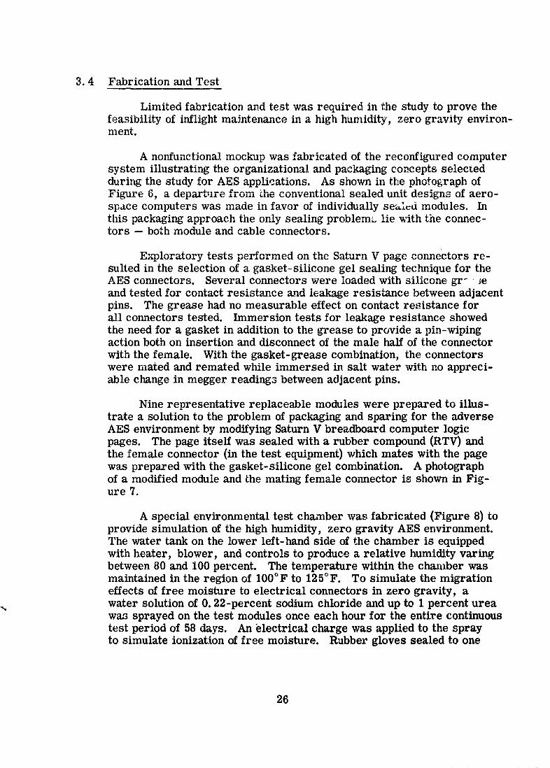
A nonfunctional mockup was fabricated of the reconfigured computersystem illustrating the organizational and packaging concepts selectedduring the study for AES applications. As shown in the photograph ofFigure 6, a depar_.h _ from _he conventional sealed uait designs of aero-space computers was made in favor of individually sea_d modules. Inthis packaging approach the only sealing problem_ lie with the connec-tors -- both module and cable connectors.
Exploratory tests performed on the Saturn V page connectors re-sulted in the selection of a gasket-silicone gel sealing technique for theAES connectors. Several connectors were loaded with silicone gr-, Jeand tested for contact resistance and leakage resistance between adjacentpins. The grease had no measurable effect on contact re,_istance forall connectors tested. Immersion tests for leakage resist_mce showedthe need for a gasket in addition to the grease to provide a pin-wipingaction both on insertion and disconnect of the male half of the connector
with the female. With the gasket-grease combination, the connectorswere mated and remated while immersed in salt water with no appreci-able change in megger readings between adjacent pins.
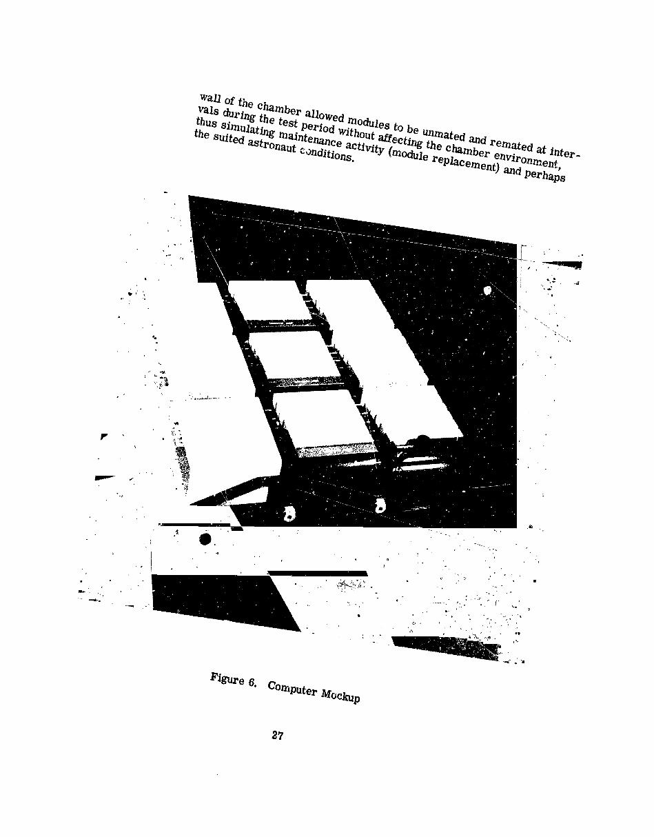
Nine representative replaceable modules were prepared to illus-trate a solution to the problem of packaging and sparing for the adverseAES environment by modifying Saturn V breadboard computer logicpages. The page itself was sealed with a rubber compound (RTV) andthe female connector (in the test equipment) which mates with the pagewas prepared with the gasket-silicone gel combination. A photographof a modified module and _he mating female connector is shown in Fig-ure 7.
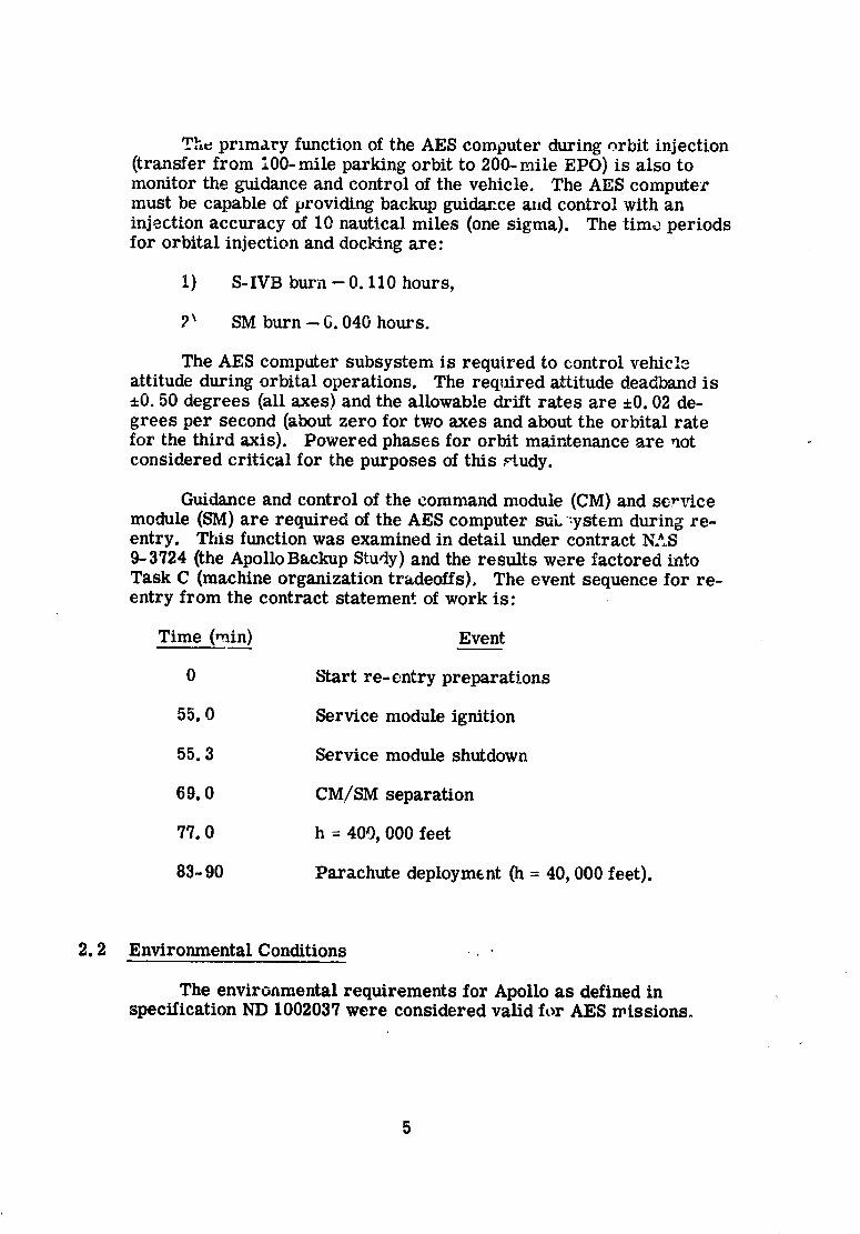
A special environmental test chamber was fabricated (Figure 8) toprovide simulation of the high humidity, zero gravity AES environment.The water tank on the lower left-hand side of the chamber is equippedwith heater, blower, and controls to produce a relative humidity varingbetween 80 and 100 percent. The temperature within the chamber wasmaintained in the region of 100°F to 125°F. To simulate the migrationeffects of free moisture to electrical connectors in zero gravity, awater solution of 0. 22-percent sodium chloride and up to 1 percent urea,%
w,_ sprayed on the test modules once each hour for the entire continuoustest period of 58 da},s. An electrical charge was applied to the sprayto simulate ionization of free moisture. Rubber gloves sealed to one
26
1966011714-031
wall of the chamber allowed modules to be unmated and remated at inter-vals during the test period without affecting the chamber environment,thus simulating maintenance activity (module replacement) and perhapsthe suited astronaut conditions.
Figure 6. Computer Mockup
27
19660117'
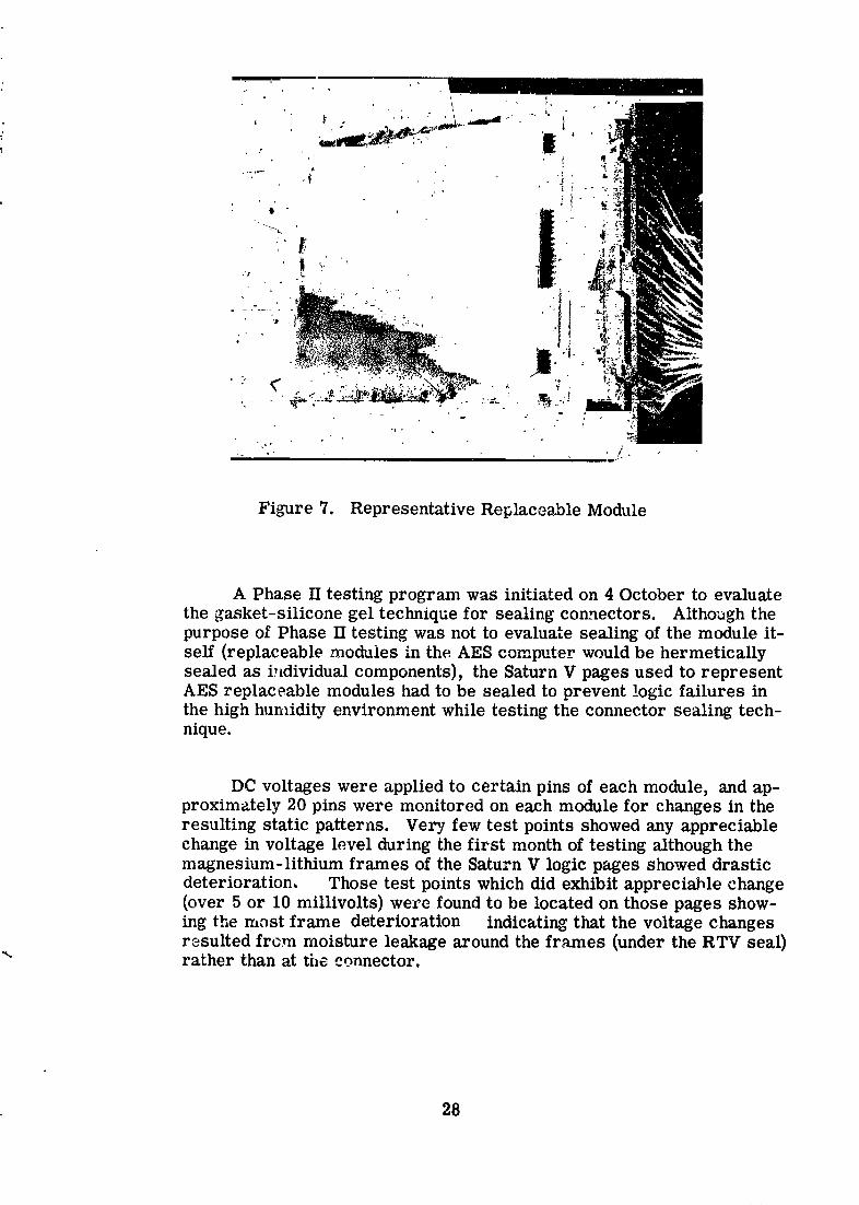
Figure 7. Representative Replaceable Module
A Phase II testing program was initiated on 4 October to evaluatethe gasket-silicone gel technique for sealing connectors. Although thepurpose of Phase II testing was not to evaluate sealing of the module it-self (replaceable modules in the AES computer would be hermeticallysealed as individual components), the Saturn V pages used to representAES replaceable modules had to be sealed to prevent logic failures inthe high humidity environment while testing the connector sealing tech-nique.
DC voltages were applied to certain pins of each module, and ap-proximately 20 pins were monitored on each module for changes in theresulting static patterns. Very few test points showed any appreciablechange in voltage level during the first month of testing although themagnesium-lithium frames of the Saturn V logic pages showed drasticdeterioration, Those test points which did exhibit appreciable change(over 5 or 10 millivolts) weze found to be located on those pages show-ing the most frame deterioration indicating that the voltage changesresulted from moisture leakage around the frames (under the RTV seal)
"_ rather than at the connector.
28
1966011714-033
29
1966011714-034
On 7 Novemuer the tests were interrupted by a failure of the testchamber. A connection came loose from the water tank causing aflooded condition and drastic changes in the temperature-humidity en-
vironment. A rash of voltage changes occurred at this time, especiallyon those modules exhibiting the most frame deterioration.
It is difficult to define a voltage change as a failure, since the op-
eration of is on-off in nature. Even the most drasticdigital systerns
' changes in voltage leveis monitored during the test may not cause alogic failure in actual practice. For the purpose of this discussion, how-
ever, a logic failure is defined as a voltage change of over 25 milUvolts.
Of the nine representative modules, six exhibited no failures untilI the test chamber failed (a test period of over a month). Two modules
survived the and exhibited no failures for the entire test period (57flood
days). One module exhibited one failure: and a second module exhibitedtwo failures after the flood. One of the modules which operated per-
t fectly up to tt.e time of the flood had to be disconnected following the teste£'aipment failure because it began to draw excessive current from thepower supplies.
One mod-ale exhibited two failures during the first month of testing.Another module lasted 20 days of testing before experiencing its firstfailure and then degraded rapidly. The ninth module experienced threefailures after only a few days of test and then stabilized until the flood,aftez which it degraded rapidly.
Only one module out of the nine had to be removed from the tester| due to drawing excessive current, however. Eight finished the test
period of 57 days.In general, the frequency of failures could be correlated with de-
terioration of the magnesium-lithium frame (causing the RTV seal tope_l off the circuit board). The failure mechanisms seemed, therefore,to be a moisture lea2_age under the edge of the RTV seal rather than bymeans of the connectors. Detailed examination and disecth_g of the failedmodules supported this conclusion.
Although it is believed that the connector sealing technique wasproven by the evaluation test, further testing is planned (under IBM fund-ing, since the AES-EPO study period has concluded) with better sealed
• modules to eliminate rao@ale failures and provide further proof of the? connector sealing cap;_bilities. These tests will be reported to NASA-
t MSC.
II 30
1966011714-035
4.0 CONCLUSIONS AND RECOMMENDATIONS
The two major objectives of the study have been achieved. ATMR computer system derived by reconfig-aring the Saturn V guidancecomputer and the Apollo backup data adapter was shown to be afeasible solution to the time critical reliability problem. Also, adetailed investigatiou of inflight maintenance (including module andchannel switching) as a means of solving the long term reliabilityprobiem was generally successful in all areas affecting maintenanceactivities including error detection, failure isolation, and modulereplacement in the high humidity, zero gravity AES environment.
4.1 Mission Requirements
The mission reliability requirements of 0. 9994 for the 90-daymission period and 0. 999999 for the critical phases of the missionwere shown by the study to be feasible in a computer system providedonly that one is willing to pay the cost of triple modular redundancy,built-in test and switching circuitry, and spares. Automatic errordetection and fault isolation can be instrumented to relieve the inflight
: crew of the nearly impossible task of diagnosing error symptoms incomplex digital systems. Automatic self-repair of the computersystem was found m the study to be legible. Also, manual repair(module replacement) was proved by laboratory test to be feasible inthe adverse AES environment.
4.2 TMR Organization
The apportioned computer-data adapter reliability was specifiedto be 0. 999999 for the critical phases of the 90-day earth polar crbitmission. The most critical phase of the mission for wh'_ch the reliabilityestimates were made was the boost phase with arL effective time period
of 10.8 hours (obtained by multiplying real boost time by estimatedenvironmental stress factors). The estimated reliability of thereconfigured computer system in its basic TMR mode of operationsomewhat exceeded the requirement. In the TMR/Simplex mode ofoperation, where a module containing a component failure may beoperated simplex while the rest of the modules operate TMR, mL even
: greater reliability marghl was realized with the reconfigured computer.
31
1966011714-036
I ofthisstudyisthata TMR machine organizationA conclusion
shouldbe consideredfor any mission containingcriticalphases duringwhich normal opelationcannotbe suspended toperform testsor to
make repah's.
i 4.3 InflightMaintenance
The apportioned computer-data adapter reliability was specified. to be 0. 9994 for the 90-day earth polar orbit mission. The estimatedreliability of the reconfigured computer system in its basic TMR modeof operation without inflight maintenance was 0. 9979. In the TMR/
t Simplex was 9984, and for the Switchable Sparemode the estimate 0.
mode (inwhich the switched-outgood module of the TM-R/Sim!:lexmodeis made available as a built-in spare in case of a second failure in the
i same module)the estimateexceeded the mission requirement.
Althoughspare modules are notrequiredto meet +_hemission
reliability requirement i/the Switchable Spare mode is instrumented,a redefinition of the critical phase is necessary if no spares arecarried on the AES-EPO mission. Since re-entry (defined as a
critical phase in the study) is the last phase of the mission, it will beinitiated with a computer system which is not fully TMR. The ac-cumulated failures over the 90 days have not been corrected byreplacing failed modules with spares so that the reliability of entry
t cannot exceed the mission reliability. The entire mission, includingre-entry, could be accomplished with a reliability exceeding 0.999,however.
The spares requirements for the TMR mode of operation (assum-ing that the TMR/Simplex or Switchable Spares modes are not instru-
i mented) are listed in Table 9. The spares requirements for the TMR/Simplex mode were not estimated but will be somewhat less. Thespares requirements for all three modes will be identical to Table 9 ifa 0.999999-reliability requirement is imposed on the re-entry phase.
I Error detection and fault isolation studies were performed usingthe Saturn V System Simulator to determine the feasibility of this
I aspect of inflight maintenance. Automatic error detection by means ofbuilt-in test circuitry and without the need for special test programs> was demonstrated in both the Saturn Y and AES computer configurations"_ with an efficiency of over 99 percent (over 99 percent of the simulated! errors were detected). Automatic failure isolation by means of built-in
test circuitry was found to be feasible to the same degree of efficiency.Error detection and diagnosis functions are therefore not required of the
I crew.
1966011714-037
The repairstudiesincludedbothmanual and automatictechniques.Manual repairwas implemented conceptuallyby providingthe crew withan error displayboard withan errc- lightindicatingeach replaceablemodule. Automatic and semiautomaticrepairconceptsincludedvariousswitchinginstrumentations,usuallyautomat.icwith manual overridecapabilities.Ifinstallationconstraintspermit, a TMR computer systemcould be instrumented with a wired-i,,_,, fourth (spare) chazmel and ._'"'-',...jautomatic error detecti m, failure isolation, and functional replacementof the failed module with a spare from the fourth channel.
Sealing studies including laboratory test proved the feasibility ofdesigning modularized equipment to operate and be maintained in a highhumidity, zero gravity environment. The conventional unit sealingtechniques requiring overpressurization, relief valves, and purgingwere abandoned in favor of sealing the individual replaceable moa_alesand providing protection for the exposed connectors. A gasket-siliconegel technique for protecting the connectors proved highly satisfactoryin laboratory tests.
4.4 General
The module and channel switching studies required in the state-ment of work led into several interesting potential capabilities for TMRorganizations. Although a thorough examination of these potentialcapabilities was beyond the scope of the study, sufficient effort wasexpended to determine that feasibility depended only upon the develop-ment of error detection and switching circuits with specific character-istics, and an appreciable amount of effort was therefore expended inthe area of detectic_ and switching.
As mentioned in the previous section, a self-repairing TMRcomputer sys,em can be realized by means of wired-in spares and
• circuitry which will automatically detect errors, isolate the failures tospecific channels within the failed modules, and switch in the sparein place of the failed element. These required detection, diagnostic,and switching functions can be supplied by the switchable voter developed
: during the study and described in Section 5 of this report.
TMR machine organiz_ion possesses inherent capabilities for:_ nmltimode operation which have not been realized in practice. A;_ TMR/Simplex mode (in which one or more modules of the machine
may be operated simplex while the remaining modules operate TMR)i:i was shown in the study to provide appreciable increase in mission
't 33
• :,_
1966011714-038
and critical phase reliabiY.ies over the conventional TMR mode. Ai Switchable Y._are mode (in which a failure can be tolerated in each of
those module_, in the TMR/Simplex mode which have switched tosimplex operation) was shown to provide an additional reliability in-
." crease over the TMR/Simplex mode.
_ thc voters are redesigned so that the three channels of theTMR organization can be functionally isolated rather than selectivelyturned off, a "nmltiprocessing" mode would be feasible in which each
:i channel c-,m operate as a separate computer. In orbital activities, forexample, one channel could perform the data management functionrelated to experiments, another channel could perform a similarfunction related to life support, and the third could perform navigationand vehicle control functions. With somewhat more complexity in theaddressing scheme (allowing each channel access _o the memories ofthe other two channels), the chammls cou!d operate independently ondifferent phases of the same complex problem. Even further, on apextremely complex problem in three dimension_, each channel couldhandle the computations involving components along one of the threecoordinate axes.
TMR machine organization seems to be especially applicable tothose missions which contain critical phases requiring extremely highreliability for relatively short periods of time and noncritical phaseswhich may be interrupted in case of failure but which require relativelylarge data handling capacity. The TMR organization provides the highreliability for the critical phases and the three independent channelsprovide the large data management capacity for the noncritical phases.
34
1966011714-039