Embed Size (px)
Citation preview
AES Algorithm for Secured Wireless Communication
Gohil Rikitaben KarsanbhaiElectronics and Communication Dept., Parul Institute of
Engineering and TechnologyVadodara, India
Mary Grace ShajanElectronics and Communication Dept., Parul Institute of
Engineering and TechnologyVadodara, India
Abstract— Data Security is primary concern for every communication system. There are many ways to provide security data that is being communicated. However, security is assured irrespective of the hackers are from the noise. This Paper describes a design of effective security for data communication by implementing AES (Advanced Encryption Standard) algorithm for encryption and decryption.
Keywords- Network security, Data transmission. Encryption, Decryption, Advanced Encryption Standard (AES),Hardware implementation
I. INTRODUCTION
Data security has become a serious issue with the advance ofcommunication technology. The aging Data Encryption Standard (DES) now can be broken with little effort. Therefore, the National Institute of Standards and Technology (NIST) announced the approval of FIPS-197, which is also named as Advanced Encryption Standard (AES), in 2001. The AES algorithm is a symmetric block cipher with low complexity and high security level.
NIST (National Institute of Standards and Technology) proposed secure hash standard (SHS). Biham and Shamir proposed differential attack, Matsui proposed linear cryptanalysis to attack DES type security system. When new encryption is proposed, cryptanalysis starts to develop to attack.
Many encryption algorithms are widely available and used in information security. They can be categorized into Symmetric (private) and Asymmetric (public) keys Encryption. In Symmetric keys encryption or secret key encryption, only one key is used to encrypt and decrypt data. DES uses one 64-bits key. Triple DES (3DES) uses three 64-bits keys. While AES uses various (128,192,256) bits keys.This Paper describes a design of effective security for data communication by implementing AES algorithm for encryption and decryption.
II. ADVANCED ENCRYPTION STANDARD
Cryptography plays an important role in the security of data. It enables us to store sensitive information or transmit it across insecure networks so that unauthorized persons cannot read it.
The basic unit for processing in the AES algorithm is a byte (a sequence of eight bits), so the input bit sequence is first transformed into byte sequence. In the next step a two-dimensional array of bytes (called the State) is built. The State array consists of four rows of bytes, each containing Nb bytes, where Nb is the block size divided by 32 (number of words). All internal operations (Cipher and Inverse Cipher) of the AES algorithms are then performed on the State array, after which its final value is copied to the output (State array is transformed back to the bit sequence).
The input and output for the AES algorithm each consist of sequences of 128 bits (digits with values of 0 or 1). These sequences will sometimes be referred to as blocks and the number of bits they contain will be referred to as their length. The Cipher Key for the AES algorithm is a sequence of 128, 192 or 256 bits.
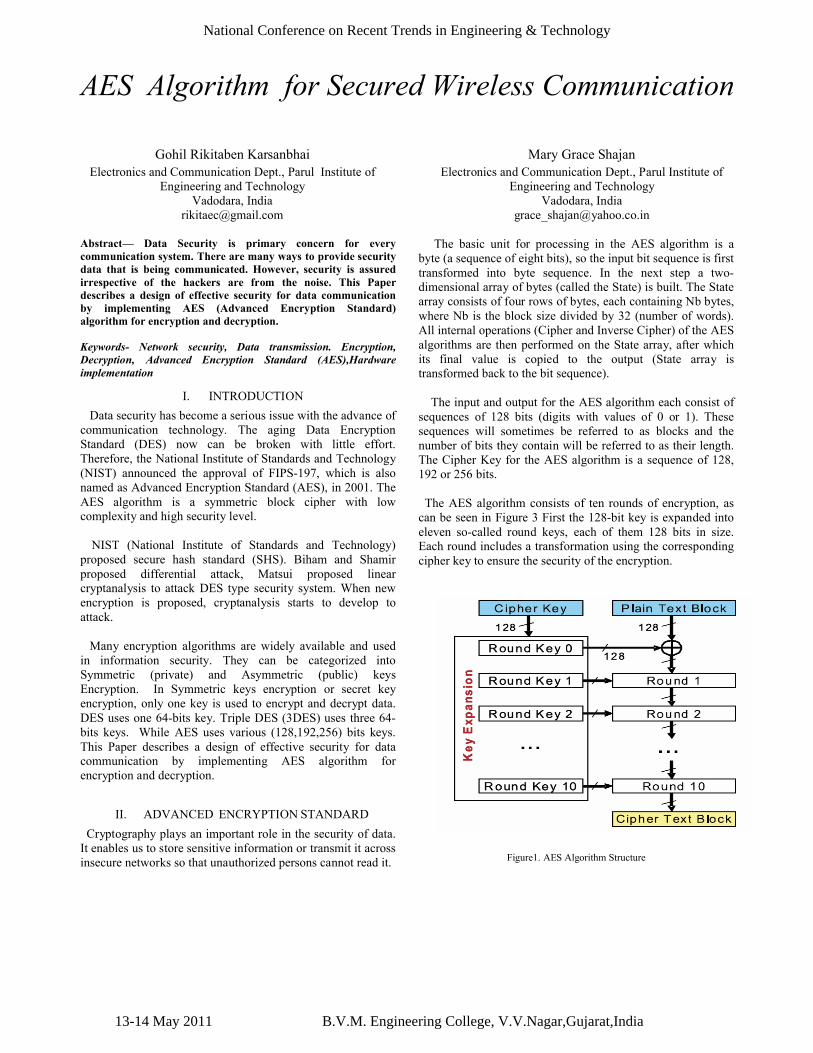
The AES algorithm consists of ten rounds of encryption, as can be seen in Figure 3 First the 128-bit key is expanded into eleven so-called round keys, each of them 128 bits in size. Each round includes a transformation using the corresponding cipher key to ensure the security of the encryption.
Figure1. AES Algorithm Structure
13-14 May 2011 B.V.M. Engineering College, V.V.Nagar,Gujarat,India
National Conference on Recent Trends in Engineering & Technology
After an initial round, during which the first round key is XORed to the plain text (Addroundkey operation), nine equally structured rounds follow. Each round consists of the following operations:
· Substitute bytes· Shift rows· Mix columns· Add round key
The tenth round is similar to rounds one to nine, but the Mix columns step is omitted.
A.Structure of Key and Input Data
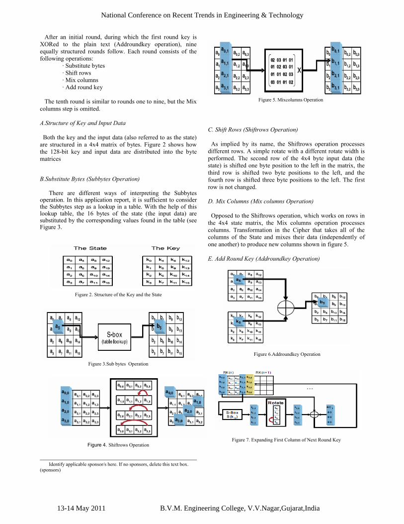
Both the key and the input data (also referred to as the state) are structured in a 4x4 matrix of bytes. Figure 2 shows how the 128-bit key and input data are distributed into the byte matrices
B.Substitute Bytes (Subbytes Operation)
There are different ways of interpreting the Subbytes operation. In this application report, it is sufficient to consider the Subbytes step as a lookup in a table. With the help of this lookup table, the 16 bytes of the state (the input data) are substituted by the corresponding values found in the table (see Figure 3.
Figure 2. Structure of the Key and the State
Figure 3.Sub bytes Operation
Figure 4. Shiftrows Operation
Figure 5. Mixcolumns Operation
C. Shift Rows (Shiftrows Operation)
As implied by its name, the Shiftrows operation processes different rows. A simple rotate with a different rotate width is performed. The second row of the 4x4 byte input data (the state) is shifted one byte position to the left in the matrix, the third row is shifted two byte positions to the left, and the fourth row is shifted three byte positions to the left. The first row is not changed.
D. Mix Columns (Mix columns Operation)
Opposed to the Shiftrows operation, which works on rows in the 4x4 state matrix, the Mix columns operation processes columns. Transformation in the Cipher that takes all of the columns of the State and mixes their data (independently of one another) to produce new columns shown in figure 5.
E. Add Round Key (Addroundkey Operation)
Figure 6.Addroundkey Operation
Figure 7. Expanding First Column of Next Round Key
Identify applicable sponsor/s here. If no sponsors, delete this text box. (sponsors)
13-14 May 2011 B.V.M. Engineering College, V.V.Nagar,Gujarat,India
National Conference on Recent Trends in Engineering & Technology
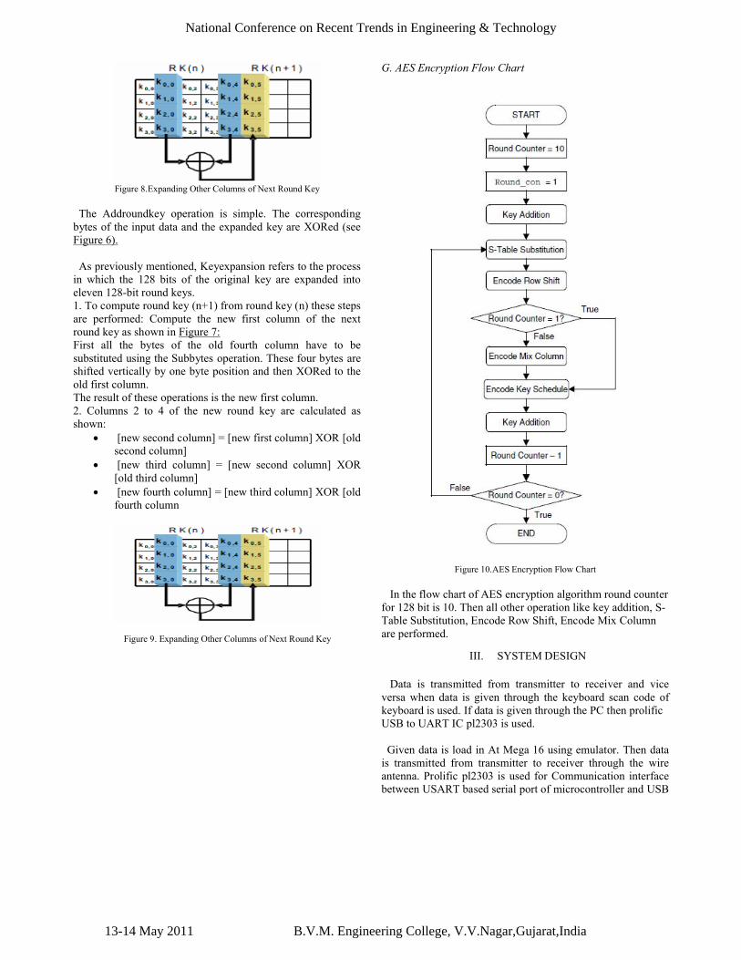
Figure 8.Expanding Other Columns of Next Round Key
The Addroundkey operation is simple. The corresponding bytes of the input data and the expanded key are XORed (see Figure 6).
As previously mentioned, Keyexpansion refers to the process in which the 128 bits of the original key are expanded into eleven 128-bit round keys.1. To compute round key (n+1) from round key (n) these steps are performed: Compute the new first column of the next round key as shown in Figure 7:First all the bytes of the old fourth column have to be substituted using the Subbytes operation. These four bytes are shifted vertically by one byte position and then XORed to the old first column.The result of these operations is the new first column.2. Columns 2 to 4 of the new round key are calculated as shown:
[new second column] = [new first column] XOR [old second column]
[new third column] = [new second column] XOR [old third column]
[new fourth column] = [new third column] XOR [old fourth column
Figure 9. Expanding Other Columns of Next Round Key
G. AES Encryption Flow Chart
Figure 10.AES Encryption Flow Chart
In the flow chart of AES encryption algorithm round counter for 128 bit is 10. Then all other operation like key addition, S-Table Substitution, Encode Row Shift, Encode Mix Column are performed.
III. SYSTEM DESIGN
Data is transmitted from transmitter to receiver and vice versa when data is given through the keyboard scan code of keyboard is used. If data is given through the PC then prolificUSB to UART IC pl2303 is used.
Given data is load in At Mega 16 using emulator. Then data is transmitted from transmitter to receiver through the wire antenna. Prolific pl2303 is used for Communication interface between USART based serial port of microcontroller and USB
13-14 May 2011 B.V.M. Engineering College, V.V.Nagar,Gujarat,India
National Conference on Recent Trends in Engineering & Technology
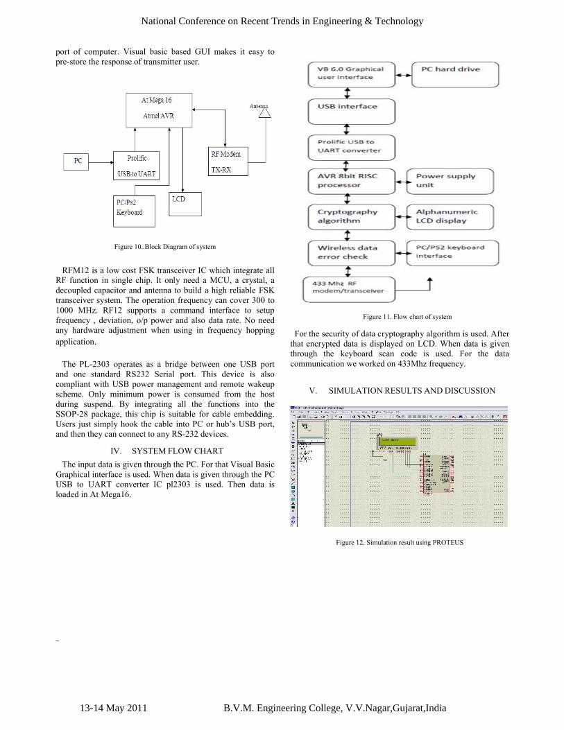
port of computer. Visual basic based GUI makes it easy to pre-store the response of transmitter user.
Figure 10..Block Diagram of system
RFM12 is a low cost FSK transceiver IC which integrate all RF function in single chip. It only need a MCU, a crystal, a decoupled capacitor and antenna to build a high reliable FSK transceiver system. The operation frequency can cover 300 to 1000 MHz. RF12 supports a command interface to setup frequency , deviation, o/p power and also data rate. No need any hardware adjustment when using in frequency hopping application.
The PL-2303 operates as a bridge between one USB port and one standard RS232 Serial port. This device is also compliant with USB power management and remote wakeup scheme. Only minimum power is consumed from the host during suspend. By integrating all the functions into the SSOP-28 package, this chip is suitable for cable embedding. Users just simply hook the cable into PC or hub’s USB port, and then they can connect to any RS-232 devices.
IV. SYSTEM FLOW CHART
The input data is given through the PC. For that Visual Basic Graphical interface is used. When data is given through the PC USB to UART converter IC pl2303 is used. Then data is loaded in At Mega16.
Figure 11. Flow chart of system
For the security of data cryptography algorithm is used. After that encrypted data is displayed on LCD. When data is given through the keyboard scan code is used. For the data communication we worked on 433Mhz frequency.
V. SIMULATION RESULTS AND DISCUSSION
Figure 12. Simulation result using PROTEUS
13-14 May 2011 B.V.M. Engineering College, V.V.Nagar,Gujarat,India
National Conference on Recent Trends in Engineering & Technology
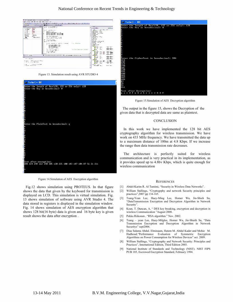
Figure 13. Simulation result using AVR STUDIO 4
Figure 14.Simulation of AES Encryption algorithm
Fig.12 shows simulation using PROTEUS. In that figure shows the data that given by the keyboard for transmission is displayed on LCD. This simulation is virtual simulation. Fig.13 shows simulation of software using AVR Studio 4. The data stored in registers is displayed in the simulation window. Fig. 14 shows simulation of AES encryption algorithm that shows 128 bit(16 byte) data is given and 16 byte key is given result shows the data after encryption .
Figure 15.Simulation of AES Decryption algorithm
The output in the figure 15, shows the Decryption of the given data that is decrypted data are same as plaintext.
CONCLUSION
In this work we have implemented the 128 bit AES cryptography algorithm for wireless transmission. We have work on 433 MHz frequency. We have transmitted the data up to a maximum distance of 100m at 4.8 Kbps. If we increase the range then data transmission rate decreases.
The architecture is perfectly suited for wireless communication and is very practical in its implementation, as it provides speed up to 4.8bv Kbps, which is quite enough for wireless communication
REFERENCES
[1] Abdel-Karim R. Al Tamimi, “Security in Wireless Data Networks”.
[2] William Stallings, “Cryptogrphy and network Security principles andpractices”,2007 pp 134-165.
[3] Tsang-Yean Lee, Huey-Ming Lee, Homer Wu, Jin-Shieh Su, “DataTransmission Encryption and Decryption Algorithm in NetworkSecurity”.
[4] Kean, T. Duncan, A, “ DES key breaking, encryption and decryption in wireless Communication ”August 2008.
[5] Pekka Riikonen , “RSA algorithm.” Nov. 2002.
[6] Tsang – yean Lee, Huey-Milglee, Homer Wu, Jin-Shieth Su, “Data Transmission Encryption and Decryption Algorithm in NetworkSecuritys” sept2006.
[7] Diaa Salama Abdul. Elminaam, Hatem M. Abdul Kader and Mohie M. Hadhoud,“Performance Evaluation of Symmetric Encryption Algorithms on Power Consumption for Wireless Devices” oct. 2009.
[8] William Stallings, “Cryptography and Network Security: Principles and Practices”, International Edition, Third Edition 2003.
[9] National Institute of Standards and Technology (NIST). NIST FIPS PUB 185, Escrowed Encryption Standard, February 1994.
13-14 May 2011 B.V.M. Engineering College, V.V.Nagar,Gujarat,India
National Conference on Recent Trends in Engineering & Technology
![STEGANO-CRYPTOGRAPHY FOR SECURED TRANSMISSION …Symmetrical hybrid based 128 bit key AES-DES algorithm for motion image transmission [5] was proposed by Vishnu, et.al. (2008). It](https://img.pdfslide.us/doc/110x75/5edcd001ad6a402d6667a563/stegano-cryptography-for-secured-transmission-symmetrical-hybrid-based-128-bit-key.jpg)