Embed Size (px)
Citation preview
Last Updated : June 8th 2011 1
AERSP 597BWind Turbine Aerodynamics
“XTurb-PSU”
Sven SchmitzAssistant Professor, Dept. of Aerospace Engineering
The Pennsylvania State [email protected]

Last Updated : June 8th 2011 2
User’s Guide
Last Updated : June 8th 2011 3
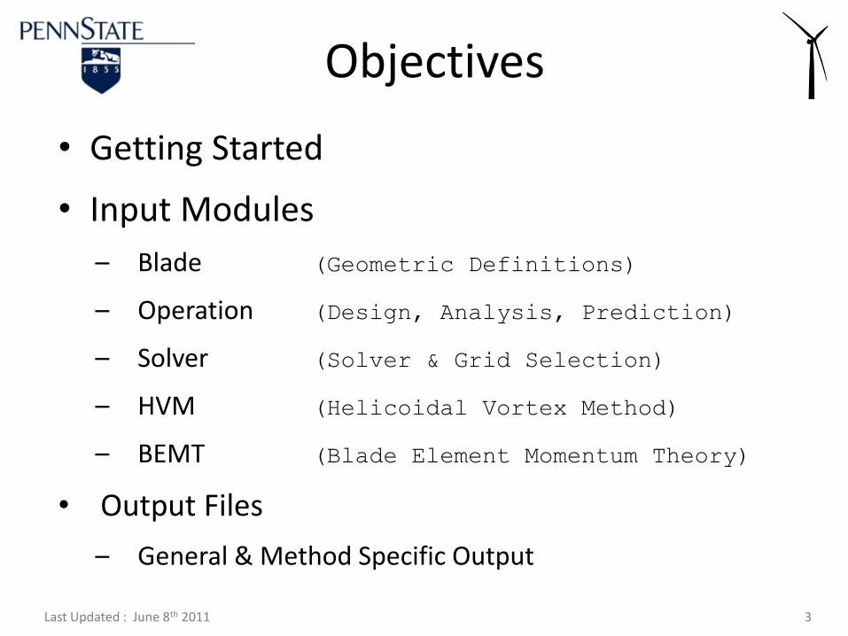
• Getting Started
• Input Modules
– Blade (Geometric Definitions)
– Operation (Design, Analysis, Prediction)
– Solver (Solver & Grid Selection)
– HVM (Helicoidal Vortex Method)
– BEMT (Blade Element Momentum Theory)
• Output Files
– General & Method Specific Output
Objectives
Last Updated : June 8th 2011 4
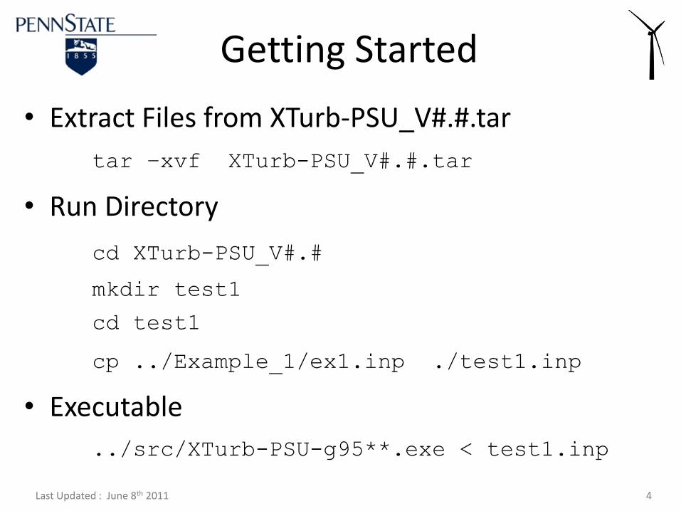
Getting Started
• Extract Files from XTurb-PSU_V#.#.tar
tar –xvf XTurb-PSU_V#.#.tar
• Run Directory
cd XTurb-PSU_V#.#
mkdir test1
cd test1
cp ../Example_1/ex1.inp ./test1.inp
• Executable
../src/XTurb-PSU-g95**.exe < test1.inp
Last Updated : June 8th 2011 5
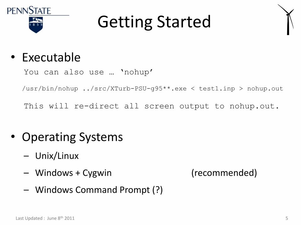
Getting Started
• ExecutableYou can also use … ‘nohup’
/usr/bin/nohup ../src/XTurb-PSU-g95**.exe < test1.inp > nohup.out
This will re-direct all screen output to nohup.out.
• Operating Systems
– Unix/Linux
– Windows + Cygwin (recommended)
– Windows Command Prompt (?)
Last Updated : June 8th 2011 6
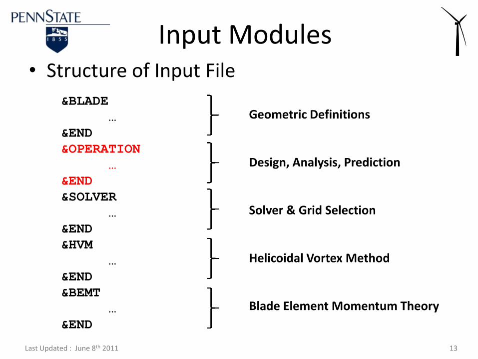
&BLADE
…
&END
&OPERATION
…
&END
&SOLVER
…
&END
&HVM
…
&END
&BEMT
…
&END
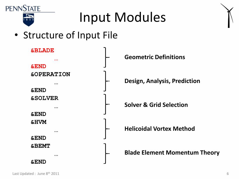
• Structure of Input File
Input Modules
Geometric Definitions
Design, Analysis, Prediction
Solver & Grid Selection
Helicoidal Vortex Method
Blade Element Momentum Theory
Last Updated : June 8th 2011 7
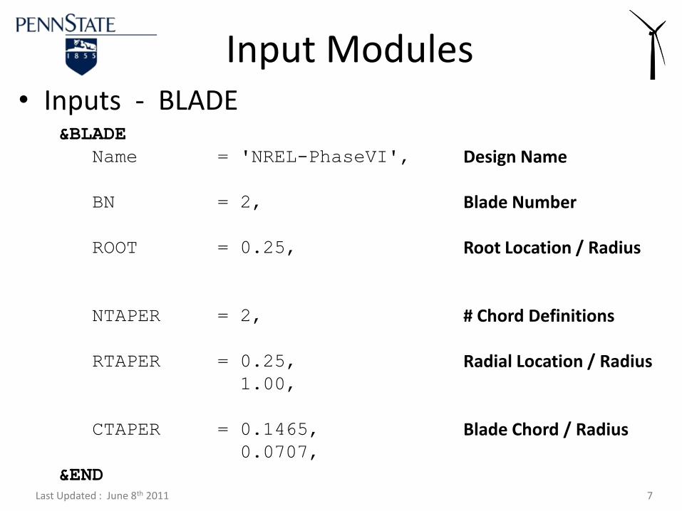
&BLADE
Name = 'NREL-PhaseVI',
BN = 2,
ROOT = 0.25,
NTAPER = 2,
RTAPER = 0.25,
1.00,
CTAPER = 0.1465,
0.0707,
&END
• Inputs - BLADE
Input Modules
Design Name
Blade Number
Root Location / Radius
# Chord Definitions
Radial Location / Radius
Blade Chord / Radius

Last Updated : June 8th 2011 8
&BLADE
NTWIST = 20,
RTWIST = 0.250,
0.267,
…
1.000,
DTWIST = 20.040,
18.074,
…
-1.816,
NAIRF = 2,
&END
• Inputs - BLADE
Input Modules
# Twist Definitions
Radial Location / Radius
Twist Angle [deg]
# Airfoil Polars
Last Updated : June 8th 2011 9
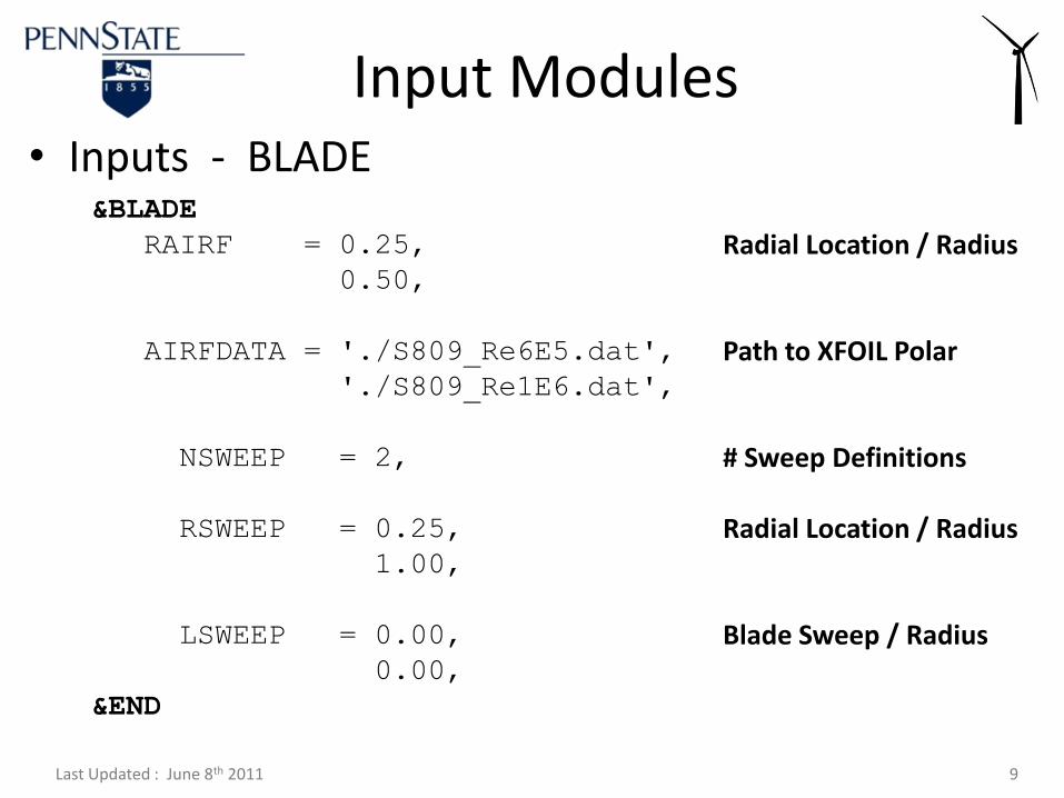
&BLADE
RAIRF = 0.25,
0.50,
AIRFDATA = './S809_Re6E5.dat',
'./S809_Re1E6.dat',
NSWEEP = 2,
RSWEEP = 0.25,
1.00,
LSWEEP = 0.00,
0.00,
&END
• Inputs - BLADE
Input Modules
Radial Location / Radius
Path to XFOIL Polar
# Sweep Definitions
Radial Location / Radius
Blade Sweep / Radius

Last Updated : June 8th 2011 10
XFOIL Version 6.8
Calculated polar for: 1. 0.
1 1 Reynolds number fixed Mach number fixed
xtrf = 1.000 (top) 1.000 (bottom)
Mach = 0.000 Re = 0.500 e 6 Ncrit = 9.000
alpha CL CD CDp CM Top Xtr Bot Xtr
------- -------- --------- --------- -------- ------- -------
0.000 0.1452 0.01352 0.00682 -0.0431 0.6141 0.5406
0.500 0.2046 0.01361 0.00689 -0.0447 0.6125 0.5425
1.000 0.2633 0.01357 0.00696 -0.0461 0.6108 0.5449
1.500 0.3223 0.01364 0.00715 -0.0474 0.6093 0.5471
… … … …
• Inputs - BLADE Example : XFOIL Polar
Input Modules
Last Updated : June 8th 2011 11
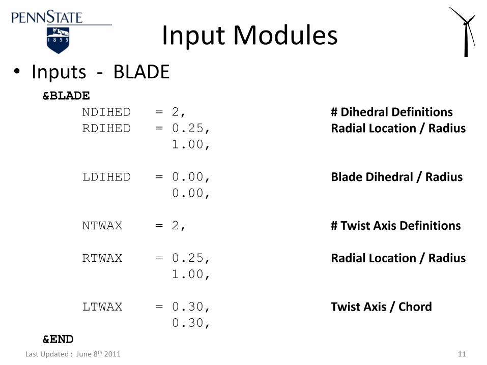
&BLADE
NDIHED = 2,
RDIHED = 0.25,
1.00,
LDIHED = 0.00,
0.00,
NTWAX = 2,
RTWAX = 0.25,
1.00,
LTWAX = 0.30,
0.30,
&END
• Inputs - BLADE
Input Modules
# Dihedral DefinitionsRadial Location / Radius
Blade Dihedral / Radius
# Twist Axis Definitions
Radial Location / Radius
Twist Axis / Chord
Last Updated : June 8th 2011 12
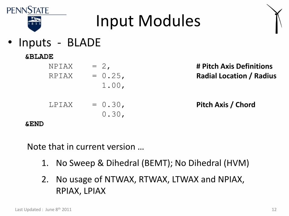
&BLADE
NPIAX = 2,
RPIAX = 0.25,
1.00,
LPIAX = 0.30,
0.30,
&END
• Inputs - BLADE
Input Modules
# Pitch Axis DefinitionsRadial Location / Radius
Pitch Axis / Chord
Note that in current version …
1. No Sweep & Dihedral (BEMT); No Dihedral (HVM)
2. No usage of NTWAX, RTWAX, LTWAX and NPIAX, RPIAX, LPIAX
Last Updated : June 8th 2011 13
&BLADE
…
&END
&OPERATION
…
&END
&SOLVER
…
&END
&HVM
…
&END
&BEMT
…
&END
• Structure of Input File
Input Modules
Geometric Definitions
Design, Analysis, Prediction
Solver & Grid Selection
Helicoidal Vortex Method
Blade Element Momentum Theory
Last Updated : June 8th 2011 14
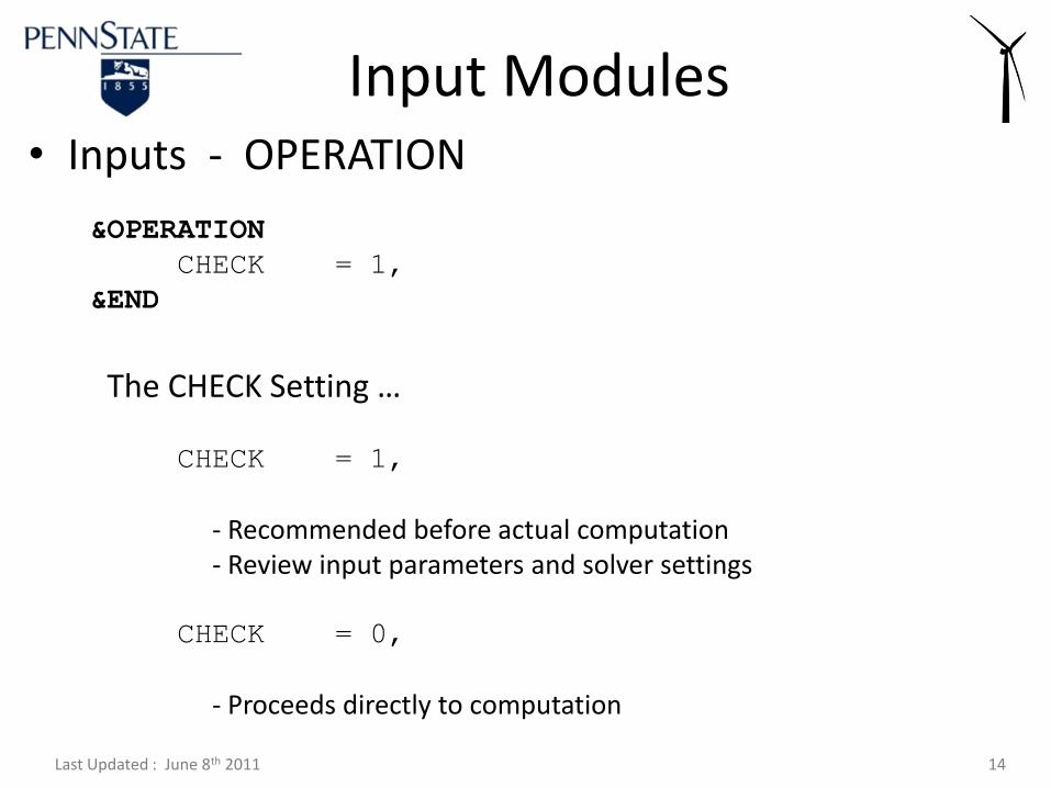
&OPERATION
CHECK = 1,
&END
• Inputs - OPERATION
Input Modules
The CHECK Setting …
CHECK = 1,
- Recommended before actual computation- Review input parameters and solver settings
CHECK = 0,
- Proceeds directly to computation
Last Updated : June 8th 2011 15
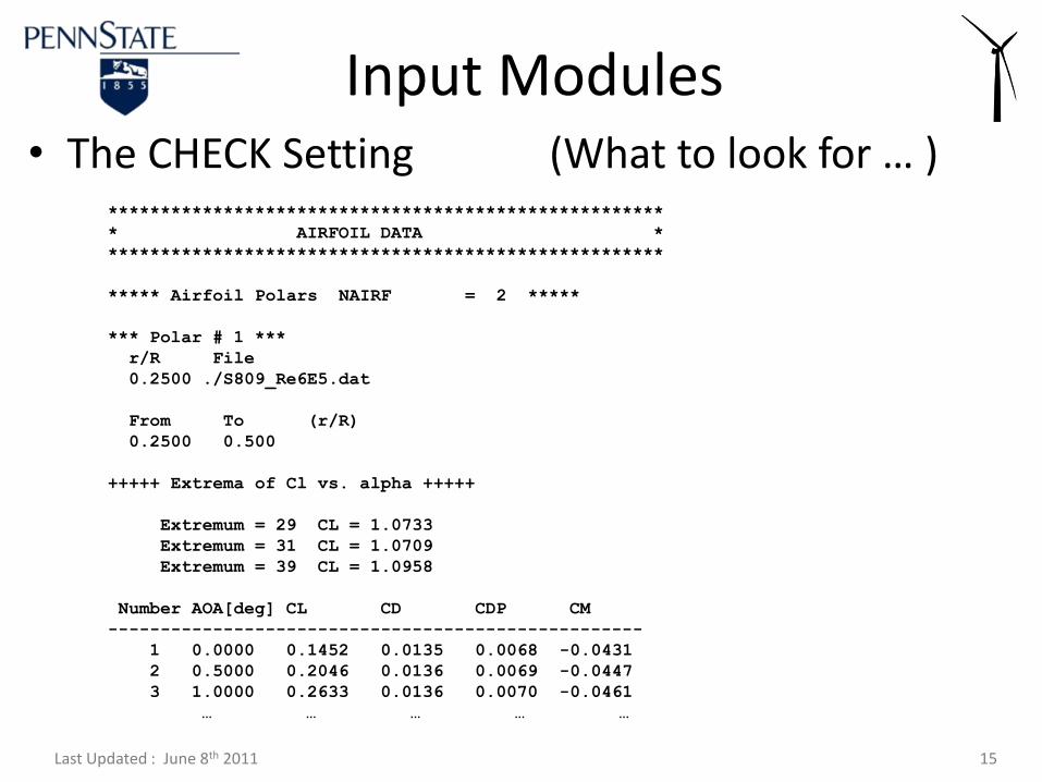
*****************************************************
* AIRFOIL DATA *
*****************************************************
***** Airfoil Polars NAIRF = 2 *****
*** Polar # 1 ***
r/R File
0.2500 ./S809_Re6E5.dat
From To (r/R)
0.2500 0.500
+++++ Extrema of Cl vs. alpha +++++
Extremum = 29 CL = 1.0733
Extremum = 31 CL = 1.0709
Extremum = 39 CL = 1.0958
Number AOA[deg] CL CD CDP CM
---------------------------------------------------
1 0.0000 0.1452 0.0135 0.0068 -0.0431
2 0.5000 0.2046 0.0136 0.0069 -0.0447
3 1.0000 0.2633 0.0136 0.0070 -0.0461
… … … … …
• The CHECK Setting (What to look for … )
Input Modules
Last Updated : June 8th 2011 16
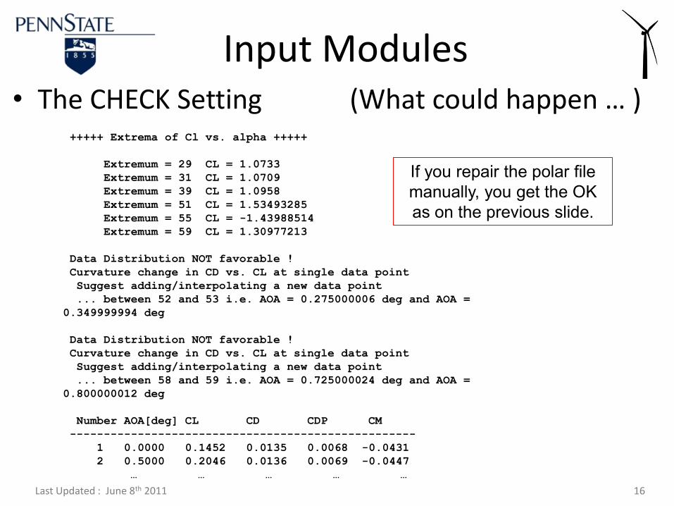
+++++ Extrema of Cl vs. alpha +++++
Extremum = 29 CL = 1.0733
Extremum = 31 CL = 1.0709
Extremum = 39 CL = 1.0958
Extremum = 51 CL = 1.53493285
Extremum = 55 CL = -1.43988514
Extremum = 59 CL = 1.30977213
Data Distribution NOT favorable !
Curvature change in CD vs. CL at single data point
Suggest adding/interpolating a new data point
... between 52 and 53 i.e. AOA = 0.275000006 deg and AOA =
0.349999994 deg
Data Distribution NOT favorable !
Curvature change in CD vs. CL at single data point
Suggest adding/interpolating a new data point
... between 58 and 59 i.e. AOA = 0.725000024 deg and AOA =
0.800000012 deg
Number AOA[deg] CL CD CDP CM
---------------------------------------------------
1 0.0000 0.1452 0.0135 0.0068 -0.0431
2 0.5000 0.2046 0.0136 0.0069 -0.0447
… … … … …
• The CHECK Setting (What could happen … )
Input Modules
If you repair the polar file
manually, you get the OK
as on the previous slide.
Last Updated : June 8th 2011 17
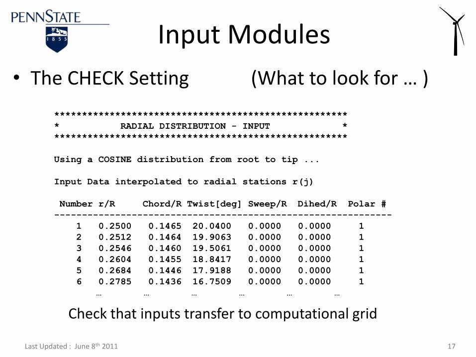
*****************************************************
* RADIAL DISTRIBUTION - INPUT *
*****************************************************
Using a COSINE distribution from root to tip ...
Input Data interpolated to radial stations r(j)
Number r/R Chord/R Twist[deg] Sweep/R Dihed/R Polar #
-------------------------------------------------------------
1 0.2500 0.1465 20.0400 0.0000 0.0000 1
2 0.2512 0.1464 19.9063 0.0000 0.0000 1
3 0.2546 0.1460 19.5061 0.0000 0.0000 1
4 0.2604 0.1455 18.8417 0.0000 0.0000 1
5 0.2684 0.1446 17.9188 0.0000 0.0000 1
6 0.2785 0.1436 16.7509 0.0000 0.0000 1
… … … … … …
• The CHECK Setting (What to look for … )
Input Modules
Check that inputs transfer to computational grid
Last Updated : June 8th 2011 18
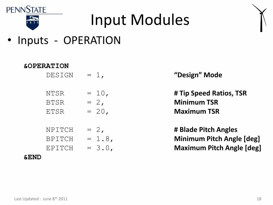
&OPERATION
DESIGN = 1,
NTSR = 10,
BTSR = 2,
ETSR = 20,
NPITCH = 2,
BPITCH = 1.8,
EPITCH = 3.0,
&END
• Inputs - OPERATION
Input Modules
“Design” Mode
# Tip Speed Ratios, TSRMinimum TSRMaximum TSR
# Blade Pitch AnglesMinimum Pitch Angle [deg]Maximum Pitch Angle [deg]
Last Updated : June 8th 2011 19
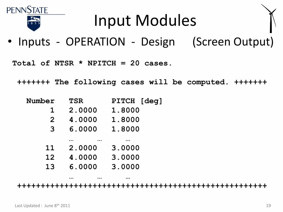
Total of NTSR * NPITCH = 20 cases.
+++++++ The following cases will be computed. +++++++
Number TSR PITCH [deg]
1 2.0000 1.8000
2 4.0000 1.8000
3 6.0000 1.8000
… … …
11 2.0000 3.0000
12 4.0000 3.0000
13 6.0000 3.0000
… … …
+++++++++++++++++++++++++++++++++++++++++++++++++++++
• Inputs - OPERATION - Design (Screen Output)
Input Modules
Last Updated : June 8th 2011 20
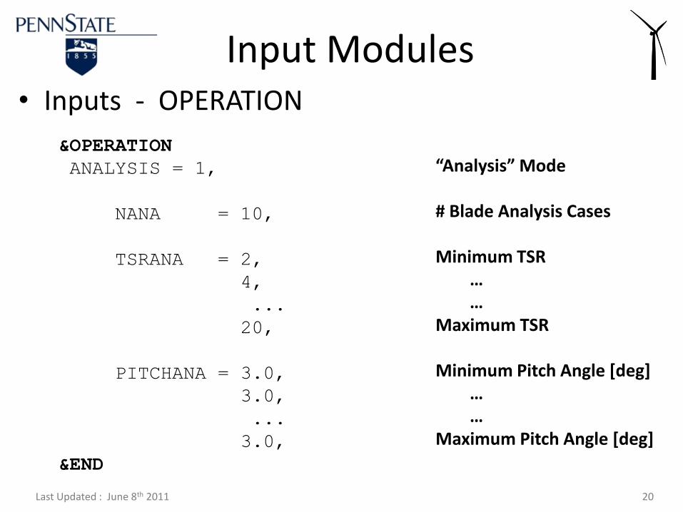
&OPERATION
ANALYSIS = 1,
NANA = 10,
TSRANA = 2,
4,
...
20,
PITCHANA = 3.0,
3.0,
...
3.0,
&END
• Inputs - OPERATION
Input Modules
“Analysis” Mode
# Blade Analysis Cases
Minimum TSR… …
Maximum TSR
Minimum Pitch Angle [deg]……
Maximum Pitch Angle [deg]
Last Updated : June 8th 2011 21
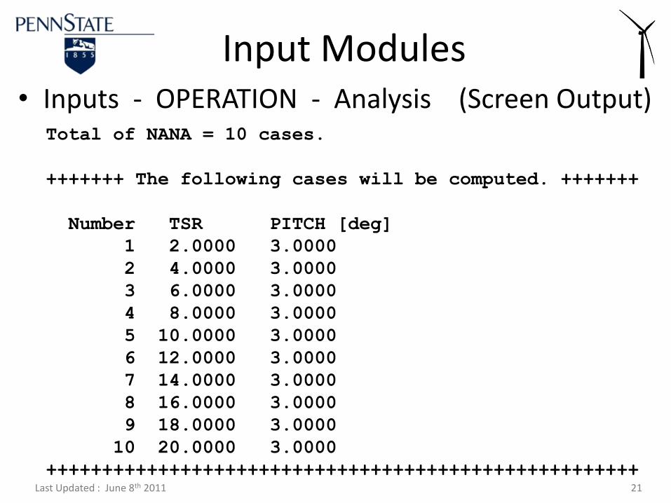
Total of NANA = 10 cases.
+++++++ The following cases will be computed. +++++++
Number TSR PITCH [deg]
1 2.0000 3.0000
2 4.0000 3.0000
3 6.0000 3.0000
4 8.0000 3.0000
5 10.0000 3.0000
6 12.0000 3.0000
7 14.0000 3.0000
8 16.0000 3.0000
9 18.0000 3.0000
10 20.0000 3.0000
+++++++++++++++++++++++++++++++++++++++++++++++++++++
• Inputs - OPERATION - Analysis (Screen Output)
Input Modules

Last Updated : June 8th 2011 22
&OPERATION
PREDICTION = 1,
BRADIUS = 5.03,
RHOAIR = 1.225,
MUAIR = 1.8E-05,
NPRE = 2,
&END
• Inputs - OPERATION
Input Modules
“Prediction” Mode
Blade Radius [m]
Air Density [kg/m^3]
Air Dynamic Visc. [kg/(m*s)]
# Prediction Cases

Last Updated : June 8th 2011 23
&OPERATION
VWIND = 5.0,
7.0,
RPMPRE = 72.0,
72.0,
PITCHPRE = 3.0,
3.0,
&END
• Inputs - OPERATION
Input Modules
Wind Speed [m/s]
Rotor RPM
Blade Pitch Angle [deg]
Last Updated : June 8th 2011 24
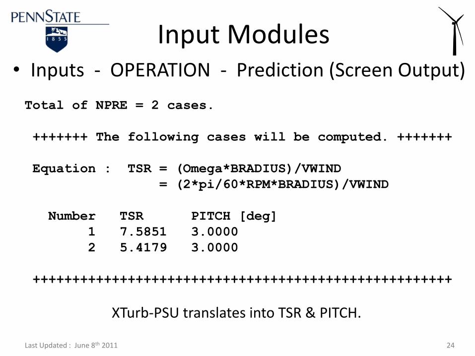
Total of NPRE = 2 cases.
+++++++ The following cases will be computed. +++++++
Equation : TSR = (Omega*BRADIUS)/VWIND
= (2*pi/60*RPM*BRADIUS)/VWIND
Number TSR PITCH [deg]
1 7.5851 3.0000
2 5.4179 3.0000
+++++++++++++++++++++++++++++++++++++++++++++++++++++
• Inputs - OPERATION - Prediction (Screen Output)
Input Modules
XTurb-PSU translates into TSR & PITCH.

Last Updated : June 8th 2011 25
Input Modules
• How is PITCH *deg+ defined … ?
V0
V0 (1-a)
Ωr (1+a’)
Vrel
αβ
Φ
Last Updated : June 8th 2011 26
Input Modules
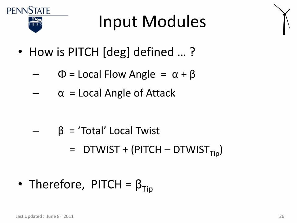
• How is PITCH *deg+ defined … ?
– Φ = Local Flow Angle = α + β
– α = Local Angle of Attack
– β = ‘Total’ Local Twist
= DTWIST + (PITCH – DTWISTTip)
• Therefore, PITCH = βTip
Last Updated : June 8th 2011 27
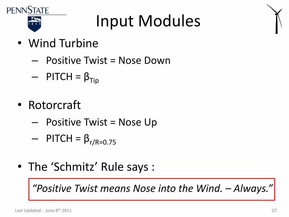
Input Modules• Wind Turbine
– Positive Twist = Nose Down
– PITCH = βTip
• Rotorcraft
– Positive Twist = Nose Up
– PITCH = βr/R=0.75
• The ‘Schmitz’ Rule says :
“Positive Twist means Nose into the Wind. – Always.”

Last Updated : June 8th 2011 28
*****************************************************
* +++ SOLUTION +++ SOLUTION +++ SOLUTION +++ *
*****************************************************
++++++++++ NEW CASE +++++++++++
Number TSR PITCH [deg]
1 7.5851 3.0000
Non-Dimensionalization :
Length Scales => Blade Radius BRADIUS
Velocity Scales => Wind Speed VWIND
In other words ... BRADIUS = VWIND = 1.00
Modifying Blade Twist from INPUT :
Adding 4.816 deg to get Tip Pitch Angle of 3. deg
• How is PITCH *deg+ defined … ? (Screen Output)
Input Modules
Last Updated : June 8th 2011 29
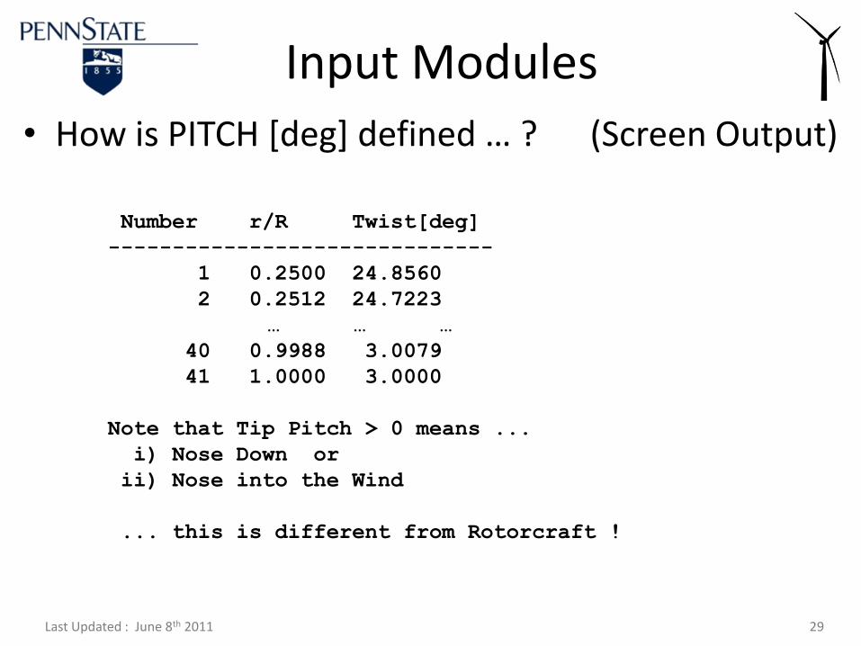
Number r/R Twist[deg]
------------------------------
1 0.2500 24.8560
2 0.2512 24.7223
… … …
40 0.9988 3.0079
41 1.0000 3.0000
Note that Tip Pitch > 0 means ...
i) Nose Down or
ii) Nose into the Wind
... this is different from Rotorcraft !
• How is PITCH *deg+ defined … ? (Screen Output)
Input Modules

Last Updated : June 8th 2011 30
&BLADE
…
&END
&OPERATION
…
&END
&SOLVER
…
&END
&HVM
…
&END
&BEMT
…
&END
• Structure of Input File
Input Modules
Geometric Definitions
Design, Analysis, Prediction
Solver & Grid Selection
Helicoidal Vortex Method
Blade Element Momentum Theory
Last Updated : June 8th 2011 31
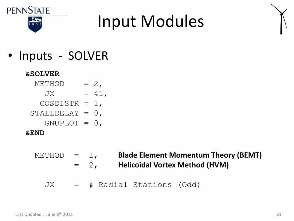
&SOLVER
METHOD = 2,
JX = 41,
COSDISTR = 1,
STALLDELAY = 0,
GNUPLOT = 0,
&END
• Inputs - SOLVER
Input Modules
METHOD = 1, Blade Element Momentum Theory (BEMT)= 2, Helicoidal Vortex Method (HVM)
JX = # Radial Stations (Odd)
Last Updated : June 8th 2011 32
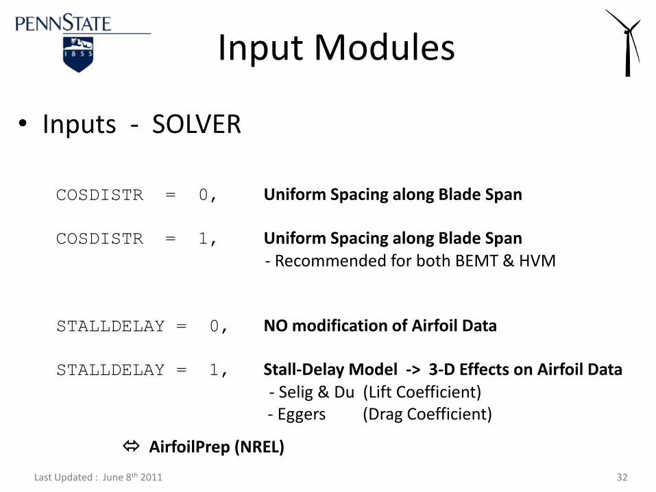
• Inputs - SOLVER
Input Modules
COSDISTR = 0, Uniform Spacing along Blade Span
COSDISTR = 1, Uniform Spacing along Blade Span- Recommended for both BEMT & HVM
STALLDELAY = 0, NO modification of Airfoil Data
STALLDELAY = 1, Stall-Delay Model -> 3-D Effects on Airfoil Data- Selig & Du (Lift Coefficient)- Eggers (Drag Coefficient)
AirfoilPrep (NREL)
Last Updated : June 8th 2011 33
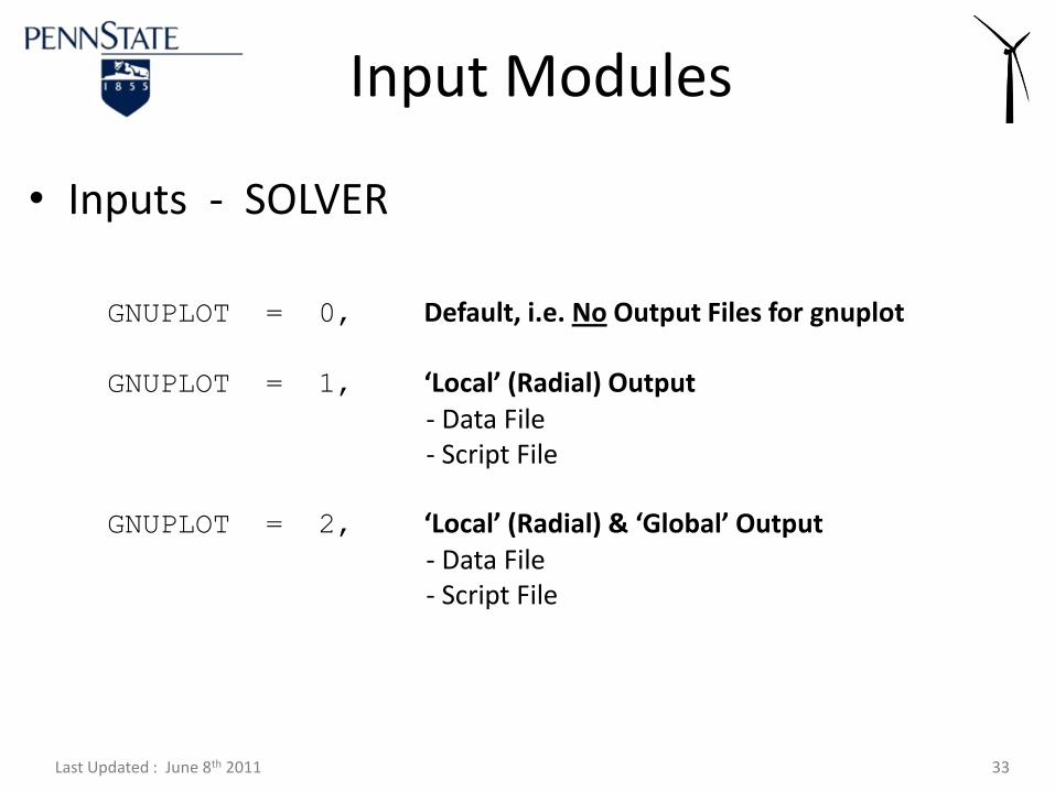
• Inputs - SOLVER
Input Modules
GNUPLOT = 0, Default, i.e. No Output Files for gnuplot
GNUPLOT = 1, ‘Local’ (Radial) Output- Data File- Script File
GNUPLOT = 2, ‘Local’ (Radial) & ‘Global’ Output- Data File- Script File

Last Updated : June 8th 2011 34
&BLADE
…
&END
&OPERATION
…
&END
&SOLVER
…
&END
&HVM
…
&END
&BEMT
…
&END
• Structure of Input File
Input Modules
Geometric Definitions
Design, Analysis, Prediction
Solver & Grid Selection
Helicoidal Vortex Method
Blade Element Momentum Theory
Last Updated : June 8th 2011 35
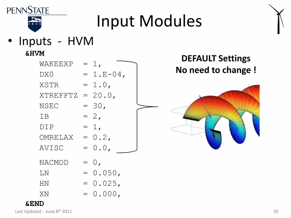
&HVM
WAKEEXP = 1,
DX0 = 1.E-04,
XSTR = 1.0,
XTREFFTZ = 20.0,
NSEC = 30,
IB = 2,
DIP = 1,
OMRELAX = 0.2,
AVISC = 0.0,
NACMOD = 0,
LN = 0.050,
HN = 0.025,
XN = 0.000,
&END
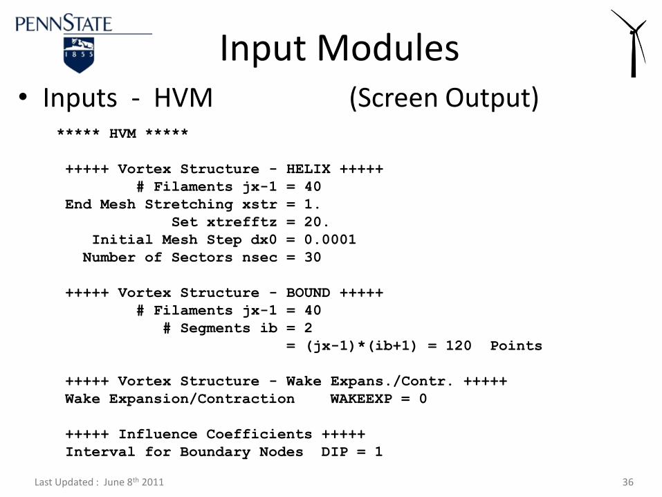
• Inputs - HVM
Input Modules
DEFAULT SettingsNo need to change !
Last Updated : June 8th 2011 36
***** HVM *****
+++++ Vortex Structure - HELIX +++++
# Filaments jx-1 = 40
End Mesh Stretching xstr = 1.
Set xtrefftz = 20.
Initial Mesh Step dx0 = 0.0001
Number of Sectors nsec = 30
+++++ Vortex Structure - BOUND +++++
# Filaments jx-1 = 40
# Segments ib = 2
= (jx-1)*(ib+1) = 120 Points
+++++ Vortex Structure - Wake Expans./Contr. +++++
Wake Expansion/Contraction WAKEEXP = 0
+++++ Influence Coefficients +++++
Interval for Boundary Nodes DIP = 1
• Inputs - HVM (Screen Output)
Input Modules
Last Updated : June 8th 2011 37
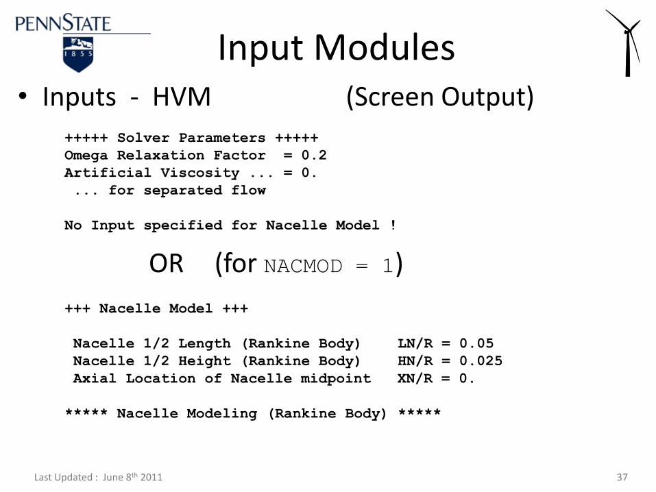
+++++ Solver Parameters +++++
Omega Relaxation Factor = 0.2
Artificial Viscosity ... = 0.
... for separated flow
No Input specified for Nacelle Model !
• Inputs - HVM (Screen Output)
OR (for NACMOD = 1)
Input Modules
+++ Nacelle Model +++
Nacelle 1/2 Length (Rankine Body) LN/R = 0.05
Nacelle 1/2 Height (Rankine Body) HN/R = 0.025
Axial Location of Nacelle midpoint XN/R = 0.
***** Nacelle Modeling (Rankine Body) *****
Last Updated : June 8th 2011 38
&BLADE
…
&END
&OPERATION
…
&END
&SOLVER
…
&END
&HVM
…
&END
&BEMT
…
&END
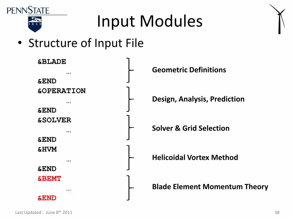
• Structure of Input File
Input Modules
Geometric Definitions
Design, Analysis, Prediction
Solver & Grid Selection
Helicoidal Vortex Method
Blade Element Momentum Theory
Last Updated : June 8th 2011 39
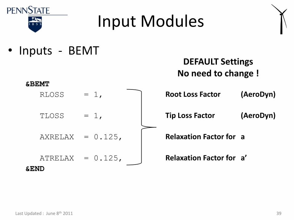
• Inputs - BEMT
Input Modules
&BEMT
RLOSS = 1,
TLOSS = 1,
AXRELAX = 0.125,
ATRELAX = 0.125,
&END
Root Loss Factor (AeroDyn)
Tip Loss Factor (AeroDyn)
Relaxation Factor for a
Relaxation Factor for a’
DEFAULT SettingsNo need to change !
Last Updated : June 8th 2011 40
• General Output
– XTurb_Output.dat
– XTurb_Output1.dat
– XTurb_Output2.dat
– XTurb_Output3.dat
• Method Specific Output
– XTurb_Output_Method.dat
– For HVM : adv.out, remain.out, bound.out, helix.out, blade_bound.out, blade_helix.out, coeff_coord.out, coeff_bound.out, coeff_helix.out, coeff_nacelle.out
Output Files
Last Updated : June 8th 2011 41
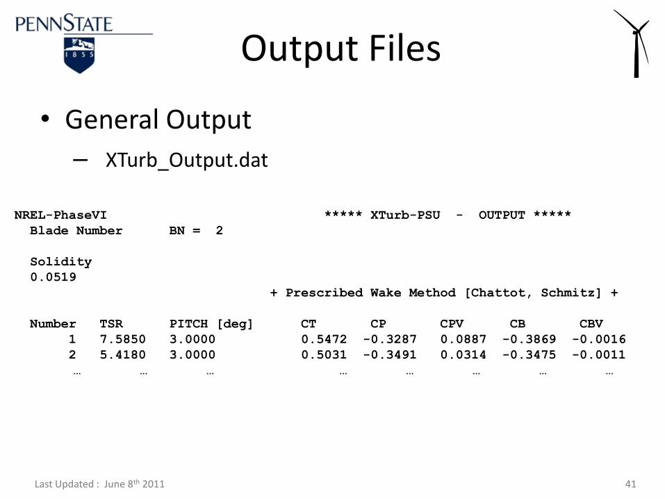
• General Output
– XTurb_Output.dat
Output Files
NREL-PhaseVI ***** XTurb-PSU - OUTPUT *****
Blade Number BN = 2
Solidity
0.0519
+ Prescribed Wake Method [Chattot, Schmitz] +
Number TSR PITCH [deg] CT CP CPV CB CBV
1 7.5850 3.0000 0.5472 -0.3287 0.0887 -0.3869 -0.0016
2 5.4180 3.0000 0.5031 -0.3491 0.0314 -0.3475 -0.0011
… … … … … … … …
Last Updated : June 8th 2011 42
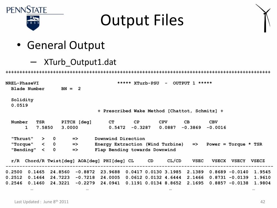
• General Output
– XTurb_Output1.dat
Output Files
+++++++++++++++++++++++++++++++++++++++++++++++++++++++++++++++++++++++++++++++++++++++++++++++
NREL-PhaseVI ***** XTurb-PSU - OUTPUT 1 *****
Blade Number BN = 2
Solidity
0.0519
+ Prescribed Wake Method [Chattot, Schmitz] +
Number TSR PITCH [deg] CT CP CPV CB CBV
1 7.5850 3.0000 0.5472 -0.3287 0.0887 -0.3869 -0.0016
"Thrust" > 0 => Downwind Direction
"Torque" < 0 => Energy Extraction (Wind Turbine) => Power = Torque * TSR
"Bending" < 0 => Flap Bending towards Downwind
r/R Chord/R Twist[deg] AOA[deg] PHI[deg] CL CD CL/CD VSEC VSECX VSECY VSECZ
------------------------------------------------------------------------------------------------
0.2500 0.1465 24.8560 -0.8872 23.9688 0.0417 0.0130 3.1985 2.1389 0.8689 -0.0140 1.9545
0.2512 0.1464 24.7223 -0.7218 24.0005 0.0612 0.0132 4.6444 2.1466 0.8731 -0.0139 1.9610
0.2546 0.1460 24.3221 -0.2279 24.0941 0.1191 0.0134 8.8652 2.1695 0.8857 -0.0138 1.9804
… … … …
Last Updated : June 8th 2011 43
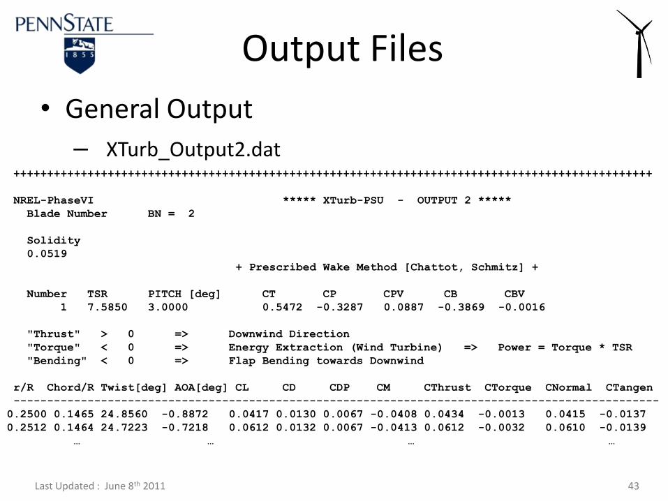
• General Output
– XTurb_Output2.dat
Output Files
+++++++++++++++++++++++++++++++++++++++++++++++++++++++++++++++++++++++++++++++++++++++++++++++
NREL-PhaseVI ***** XTurb-PSU - OUTPUT 2 *****
Blade Number BN = 2
Solidity
0.0519
+ Prescribed Wake Method [Chattot, Schmitz] +
Number TSR PITCH [deg] CT CP CPV CB CBV
1 7.5850 3.0000 0.5472 -0.3287 0.0887 -0.3869 -0.0016
"Thrust" > 0 => Downwind Direction
"Torque" < 0 => Energy Extraction (Wind Turbine) => Power = Torque * TSR
"Bending" < 0 => Flap Bending towards Downwind
r/R Chord/R Twist[deg] AOA[deg] CL CD CDP CM CThrust CTorque CNormal CTangen
------------------------------------------------------------------------------------------------
0.2500 0.1465 24.8560 -0.8872 0.0417 0.0130 0.0067 -0.0408 0.0434 -0.0013 0.0415 -0.0137
0.2512 0.1464 24.7223 -0.7218 0.0612 0.0132 0.0067 -0.0413 0.0612 -0.0032 0.0610 -0.0139
… … … …
Last Updated : June 8th 2011 44
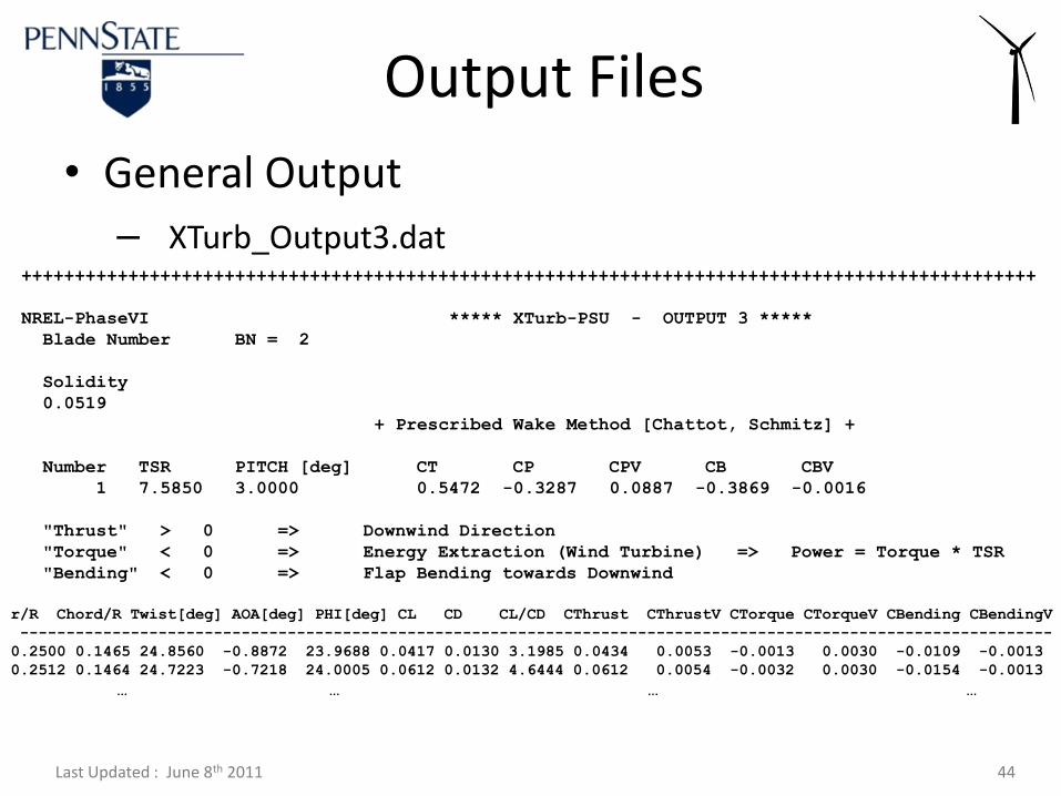
• General Output
– XTurb_Output3.dat
Output Files
+++++++++++++++++++++++++++++++++++++++++++++++++++++++++++++++++++++++++++++++++++++++++++++++
NREL-PhaseVI ***** XTurb-PSU - OUTPUT 3 *****
Blade Number BN = 2
Solidity
0.0519
+ Prescribed Wake Method [Chattot, Schmitz] +
Number TSR PITCH [deg] CT CP CPV CB CBV
1 7.5850 3.0000 0.5472 -0.3287 0.0887 -0.3869 -0.0016
"Thrust" > 0 => Downwind Direction
"Torque" < 0 => Energy Extraction (Wind Turbine) => Power = Torque * TSR
"Bending" < 0 => Flap Bending towards Downwind
r/R Chord/R Twist[deg] AOA[deg] PHI[deg] CL CD CL/CD CThrust CThrustV CTorque CTorqueV CBending CBendingV
----------------------------------------------------------------------------------------------------------------
0.2500 0.1465 24.8560 -0.8872 23.9688 0.0417 0.0130 3.1985 0.0434 0.0053 -0.0013 0.0030 -0.0109 -0.0013
0.2512 0.1464 24.7223 -0.7218 24.0005 0.0612 0.0132 4.6444 0.0612 0.0054 -0.0032 0.0030 -0.0154 -0.0013
… … … …
Last Updated : June 8th 2011 45
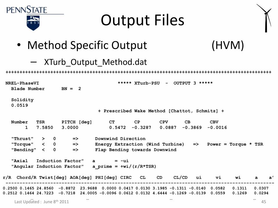
• Method Specific Output (HVM)
– XTurb_Output_Method.dat
Output Files
+++++++++++++++++++++++++++++++++++++++++++++++++++++++++++++++++++++++++++++++++++++++++++++++
NREL-PhaseVI ***** XTurb-PSU - OUTPUT 3 *****
Blade Number BN = 2
Solidity
0.0519
+ Prescribed Wake Method [Chattot, Schmitz] +
Number TSR PITCH [deg] CT CP CPV CB CBV
1 7.5850 3.0000 0.5472 -0.3287 0.0887 -0.3869 -0.0016
"Thrust" > 0 => Downwind Direction
"Torque" < 0 => Energy Extraction (Wind Turbine) => Power = Torque * TSR
"Bending" < 0 => Flap Bending towards Downwind
"Axial Induction Factor" a = -ui
"Angular Induction Factor" a_prime = +wi/(r/R*TSR)
r/R Chord/R Twist[deg] AOA[deg] PHI[deg] CIRC CL CD CL/CD ui vi wi a a’
------------------------------------------------------------------------------------------------
0.2500 0.1465 24.8560 -0.8872 23.9688 0.0000 0.0417 0.0130 3.1985 -0.1311 -0.0140 0.0582 0.1311 0.0307
0.2512 0.1464 24.7223 -0.7218 24.0005 -0.0096 0.0612 0.0132 4.6444 -0.1269 -0.0139 0.0559 0.1269 0.0294
… … … …
Last Updated : June 8th 2011 46
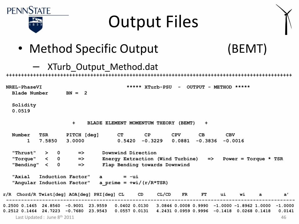
• Method Specific Output (BEMT)
– XTurb_Output_Method.dat
Output Files
+++++++++++++++++++++++++++++++++++++++++++++++++++++++++++++++++++++++++++++++++++++++++++++++
NREL-PhaseVI ***** XTurb-PSU - OUTPUT - METHOD *****
Blade Number BN = 2
Solidity
0.0519
+ BLADE ELEMENT MOMENTUM THEORY (BEMT) +
Number TSR PITCH [deg] CT CP CPV CB CBV
1 7.5850 3.0000 0.5420 -0.3229 0.0881 -0.3836 -0.0016
"Thrust" > 0 => Downwind Direction
"Torque" < 0 => Energy Extraction (Wind Turbine) => Power = Torque * TSR
"Bending" < 0 => Flap Bending towards Downwind
"Axial Induction Factor" a = -ui
"Angular Induction Factor" a_prime = +wi/(r/R*TSR)
r/R Chord/R Twist[deg] AOA[deg] PHI[deg] CL CD CL/CD FR FT ui wi a a’
------------------------------------------------------------------------------------------------
0.2500 0.1465 24.8560 -0.9001 23.9559 0.0402 0.0130 3.0846 0.0008 0.9990 -1.0000 -1.8962 1.0000 -1.0000
0.2512 0.1464 24.7223 -0.7680 23.9543 0.0557 0.0131 4.2431 0.0959 0.9996 -0.1418 0.0268 0.1418 0.0141
Last Updated : June 8th 2011 47
• Convergence Output
– XTurb_Convergence.dat
Gives some information on convergence problems that were encountered during the solution process.
Is quite helpful to isolate specific cases of TSR and Tip Pitch that may produce non-physical results.
Output File - Convergence
Last Updated : June 8th 2011 48
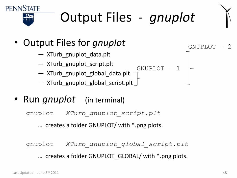
• Output Files for gnuplot— XTurb_gnuplot_data.plt
— XTurb_gnuplot_script.plt
— XTurb_gnuplot_global_data.plt
— XTurb_gnuplot_global_script.plt
• Run gnuplot (in terminal)
gnuplot XTurb_gnuplot_script.plt
… creates a folder GNUPLOT/ with *.png plots.
gnuplot XTurb_gnuplot_global_script.plt
… creates a folder GNUPLOT_GLOBAL/ with *.png plots.
Output Files - gnuplot
GNUPLOT = 1
GNUPLOT = 2

Last Updated : June 8th 2011 49
• Unsteady HVM – Shed Wake
• Vortex Rollup in HVM
• Optimization in HVM
• Tower Shadow Model
• Stall-Delay Model
• Wind Farm Wake Modeling
=> M.S. & Ph.D. Theses !!!
Future DevelopmentsXTurb-PSU