Embed Size (px)
Citation preview
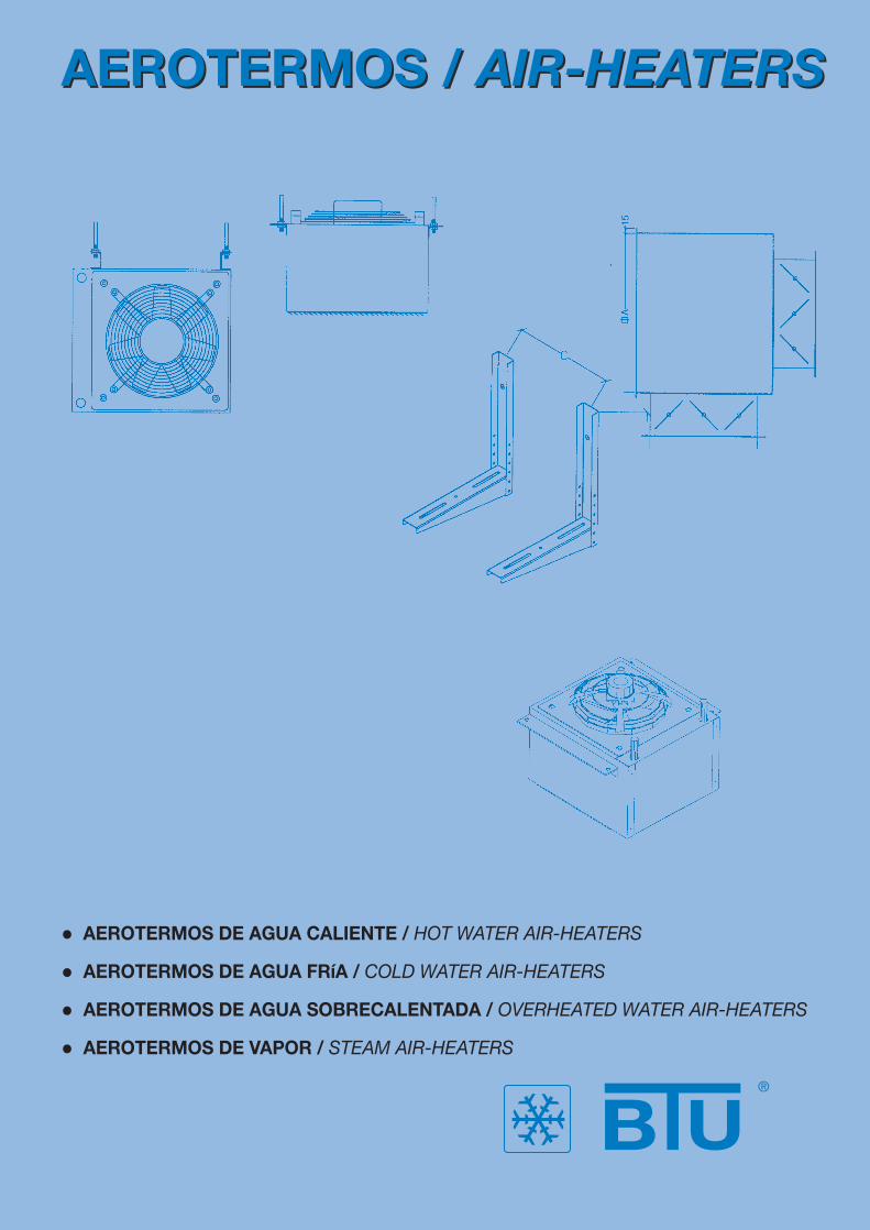
• AEROTERMOS DE AGUA CALIENTE / HOT WATER AIR-HEATERS
• AEROTERMOS DE AGUA FRíA / COLD WATER AIR-HEATERS
• AEROTERMOS DE AGUA SOBRECALENTADA / OVERHEATED WATER AIR-HEATERS
• AEROTERMOS DE VAPOR / STEAM AIR-HEATERS
AEROTERMOS / AIR-HEATERSAEROTERMOS / AIR-HEATERS
Pág. 2
AEROTERMOS DE AGUA CALIENTE, FRÍA, SOBRECALENTADA O VAPOR
HOT WATER, COLD WATER, OVERHEATED WATER AND STEAM AIR-HEATERS
INTRODUCTION
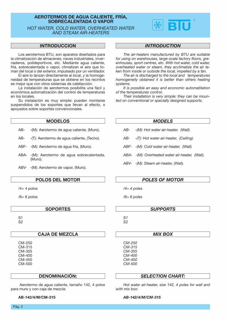
The air-heaters manufactured by BTU are suitablefor using on warehouses, large-scale factory floors, gre-enhouses, sport centres, etc. With hot water, cold water,overheated water or steam, they acclimatize the air ta-ken from inside or outside the local, impelled by a fan.
The air is discharged to the local and temperatureshomogeneity obtained it is better than others heatingsystems.
It is possible an easy and economic automatitationof the temperatures control.
Their installation is very simple: they can be moun-ted on conventional or specially designed supports.
MODELS
AB- -(M): Hot water air-heater, (Wall).
AB- -(T): Hot water air-heater, (Ceiling).
ABF- -(M): Cold water air-heater, (Wall).
ABA- -(M): Overheated water air-heater, (Wall).
ABV- -(M): Steam air-heater, (Wall).
POLES OF MOTOR
/4= 4 poles
/6= 6 poles
SUPPORTS
S1S2
MIX BOX
CM-250CM-315CM-355CM-400CM-450CM-500
SELECTION CHART:
Hot water air-heater, size 142, 4 poles for wall andwith mix box:
AB-142/4/M/CM-315
INTRODUCCION
Los aerotermos BTU, son aparatos diseñados parala climatización de almacenes, naves industriales, inver-naderos, polideportivos, etc. Mediante agua caliente,fría, sobrecalentada o vapor, climatizan el aire que to-man del local o del exterior, impulsado por un ventilador.
El aire lo lanzan directamente al local, y la homoge-neidad de temperaturas que se obtiene en los recintoses mejor que con otros sistemas de calefacción.
La instalación de aerotermos posibilita una fácil yeconómica automatización del control de temperaturasen los locales.
Su instalación es muy simple: pueden montarsesuspendidos de los soportes que llevan al efecto, oapoyados sobre soportes convencionales.
MODELOS
AB- -(M): Aerotermo de agua caliente, (Muro).
AB- -(T): Aerotermo de agua caliente, (Techo).
ABF- -(M): Aerotermo de agua fría, (Muro).
ABA- -(M): Aerotermo de agua sobrecalentada,(Muro).
ABV- -(M): Aerotermo de vapor, (Muro).
POLOS DEL MOTOR
/4= 4 polos
/6= 6 polos
SOPORTES
S1S2
CAJA DE MEZCLA
CM-250CM-315CM-355CM-400CM-450CM-500
DENOMINACIÓN:
Aerotermo de agua caliente, tamaño 142, 4 polospara muro y con caja de mezcla:
AB-142/4/M/CM-315
Pág. 3
AEROTERMOS DE AGUA CALIENTE, FRÍA, SOBRECALENTADA O VAPOR
HOT WATER, COLD WATER, OVERHEATED WATER AND STEAM AIR-HEATERS
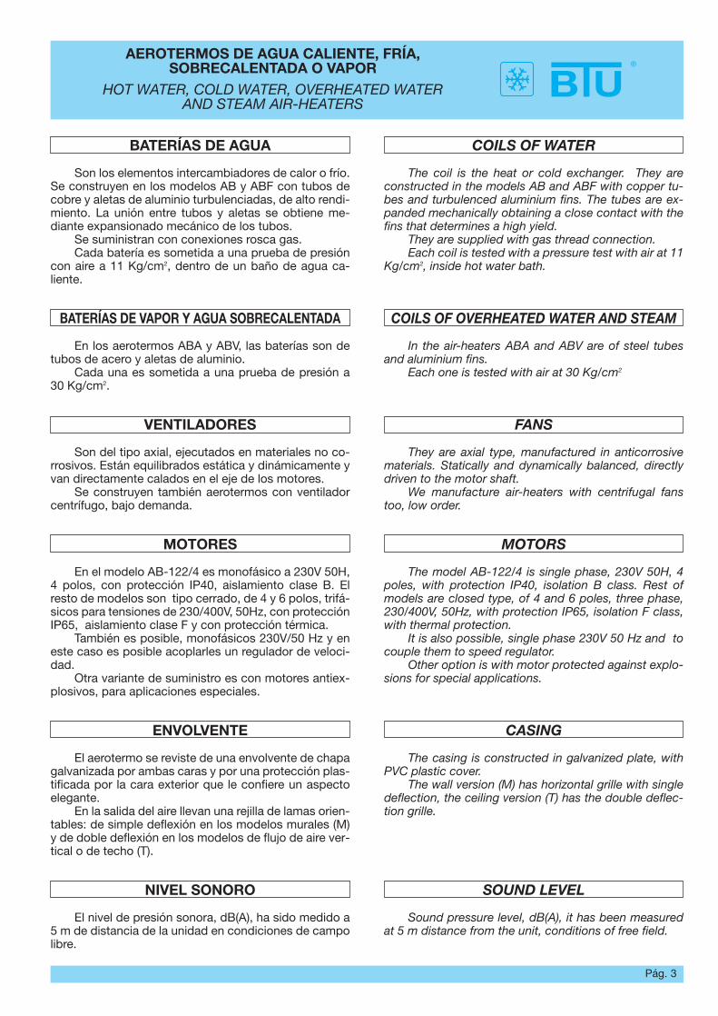
BATERÍAS DE AGUA
Son los elementos intercambiadores de calor o frío.Se construyen en los modelos AB y ABF con tubos decobre y aletas de aluminio turbulenciadas, de alto rendi-miento. La unión entre tubos y aletas se obtiene me-diante expansionado mecánico de los tubos.
Se suministran con conexiones rosca gas.Cada batería es sometida a una prueba de presión
con aire a 11 Kg/cm2, dentro de un baño de agua ca-liente.
BATERÍAS DE VAPOR Y AGUA SOBRECALENTADA
En los aerotermos ABA y ABV, las baterías son detubos de acero y aletas de aluminio.
Cada una es sometida a una prueba de presión a30 Kg/cm2.
VENTILADORES
Son del tipo axial, ejecutados en materiales no co-rrosivos. Están equilibrados estática y dinámicamente yvan directamente calados en el eje de los motores.
Se construyen también aerotermos con ventiladorcentrífugo, bajo demanda.
MOTORES
En el modelo AB-122/4 es monofásico a 230V 50H,4 polos, con protección IP40, aislamiento clase B. Elresto de modelos son tipo cerrado, de 4 y 6 polos, trifá-sicos para tensiones de 230/400V, 50Hz, con protecciónIP65, aislamiento clase F y con protección térmica.
También es posible, monofásicos 230V/50 Hz y eneste caso es posible acoplarles un regulador de veloci-dad.
Otra variante de suministro es con motores antiex-plosivos, para aplicaciones especiales.
ENVOLVENTE
El aerotermo se reviste de una envolvente de chapagalvanizada por ambas caras y por una protección plas-tificada por la cara exterior que le confiere un aspectoelegante.
En la salida del aire llevan una rejilla de lamas orien-tables: de simple deflexión en los modelos murales (M)y de doble deflexión en los modelos de flujo de aire ver-tical o de techo (T).
NIVEL SONORO
El nivel de presión sonora, dB(A), ha sido medido a5 m de distancia de la unidad en condiciones de campolibre.
COILS OF WATER
The coil is the heat or cold exchanger. They areconstructed in the models AB and ABF with copper tu-bes and turbulenced aluminium fins. The tubes are ex-panded mechanically obtaining a close contact with thefins that determines a high yield.
They are supplied with gas thread connection. Each coil is tested with a pressure test with air at 11
Kg/cm2, inside hot water bath.
COILS OF OVERHEATED WATER AND STEAM
In the air-heaters ABA and ABV are of steel tubesand aluminium fins.
Each one is tested with air at 30 Kg/cm2
FANS
They are axial type, manufactured in anticorrosivematerials. Statically and dynamically balanced, directlydriven to the motor shaft.
We manufacture air-heaters with centrifugal fanstoo, low order.
MOTORS
The model AB-122/4 is single phase, 230V 50H, 4poles, with protection IP40, isolation B class. Rest ofmodels are closed type, of 4 and 6 poles, three phase,230/400V, 50Hz, with protection IP65, isolation F class,with thermal protection.
It is also possible, single phase 230V 50 Hz and tocouple them to speed regulator.
Other option is with motor protected against explo-sions for special applications.
CASING
The casing is constructed in galvanized plate, withPVC plastic cover.
The wall version (M) has horizontal grille with singledeflection, the ceiling version (T) has the double deflec-tion grille.
SOUND LEVEL
Sound pressure level, dB(A), it has been measuredat 5 m distance from the unit, conditions of free field.
Pág. 4
AEROTERMOS AGUA CALIENTEHOT WATER AIR-HEATERS
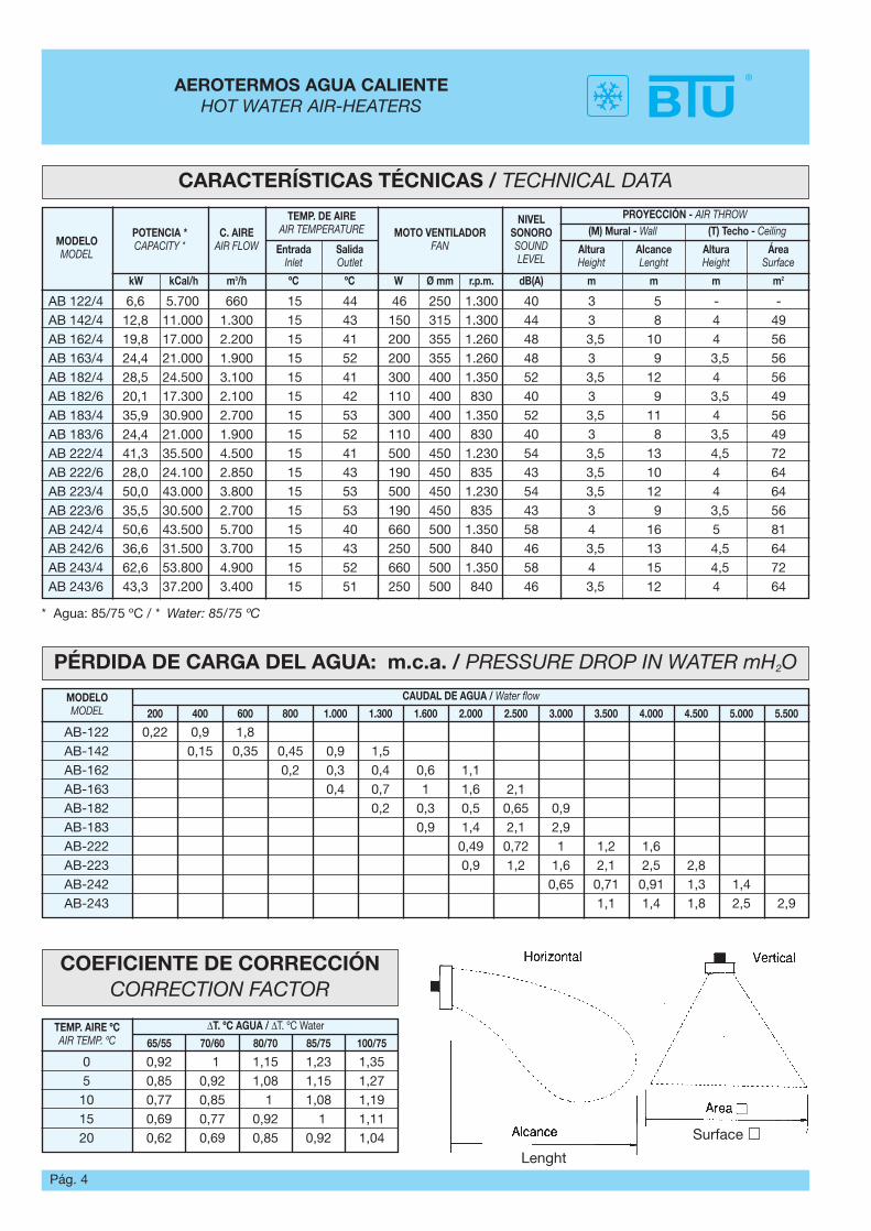
CARACTERÍSTICAS TÉCNICAS / TECHNICAL DATA
PÉRDIDA DE CARGA DEL AGUA: m.c.a. / PRESSURE DROP IN WATER mH2O
MODELOMODEL
POTENCIA *CAPACITY *
C. AIREAIR FLOW
TEMP. DE AIREAIR TEMPERATURE MOTO VENTILADOR
FAN
NIVELSONOROSOUNDLEVEL
PROYECCIÓN - AIR THROW(M) Mural - Wall (T) Techo - Ceiling
Altura Height
AlcanceLenght
AlturaHeight
ÁreaSurface
EntradaInlet
SalidaOutlet
kW kCal/h m3/h W Ø mm r.p.m. dB(A) m m m m2ºC ºC
AB 122/4 6,6 5.700 660 15 44 46 250 1.300 40 3 5 - -AB 142/4 12,8 11.000 1.300 15 43 150 315 1.300 44 3 8 4 49AB 162/4 19,8 17.000 2.200 15 41 200 355 1.260 48 3,5 10 4 56AB 163/4 24,4 21.000 1.900 15 52 200 355 1.260 48 3 9 3,5 56AB 182/4 28,5 24.500 3.100 15 41 300 400 1.350 52 3,5 12 4 56AB 182/6 20,1 17.300 2.100 15 42 110 400 830 40 3 9 3,5 49AB 183/4 35,9 30.900 2.700 15 53 300 400 1.350 52 3,5 11 4 56AB 183/6 24,4 21.000 1.900 15 52 110 400 830 40 3 8 3,5 49AB 222/4 41,3 35.500 4.500 15 41 500 450 1.230 54 3,5 13 4,5 72AB 222/6 28,0 24.100 2.850 15 43 190 450 835 43 3,5 10 4 64AB 223/4 50,0 43.000 3.800 15 53 500 450 1.230 54 3,5 12 4 64AB 223/6 35,5 30.500 2.700 15 53 190 450 835 43 3 9 3,5 56AB 242/4 50,6 43.500 5.700 15 40 660 500 1.350 58 4 16 5 81AB 242/6 36,6 31.500 3.700 15 43 250 500 840 46 3,5 13 4,5 64AB 243/4 62,6 53.800 4.900 15 52 660 500 1.350 58 4 15 4,5 72AB 243/6 43,3 37.200 3.400 15 51 250 500 840 46 3,5 12 4 64
* Agua: 85/75 ºC / * Water: 85/75 ºC
MODELOMODEL
CAUDAL DE AGUA / Water flow
200 400 600 800 1.000 1.300 1.600 2.000 2.500 3.000 3.500 4.000 4.500 5.000 5.500
AB-122 0,22 0,9 1,8AB-142 0,15 0,35 0,45 0,9 1,5AB-162 0,2 0,3 0,4 0,6 1,1AB-163 0,4 0,7 1 1,6 2,1AB-182 0,2 0,3 0,5 0,65 0,9AB-183 0,9 1,4 2,1 2,9AB-222 0,49 0,72 1 1,2 1,6AB-223 0,9 1,2 1,6 2,1 2,5 2,8AB-242 0,65 0,71 0,91 1,3 1,4AB-243 1,1 1,4 1,8 2,5 2,9
COEFICIENTE DE CORRECCIÓNCORRECTION FACTOR
TEMP. AIRE ºCAIR TEMP. ºC
∆T. ºC AGUA / ∆T. ºC Water
65/55 70/60 80/70 85/75 100/75
0 0,92 1 1,15 1,23 1,355 0,85 0,92 1,08 1,15 1,2710 0,77 0,85 1 1,08 1,1915 0,69 0,77 0,92 1 1,1120 0,62 0,69 0,85 0,92 1,04
Lenght
Surface
Pág. 5
AEROTERMOS AGUA CALIENTEHOT WATER AIR-HEATERS
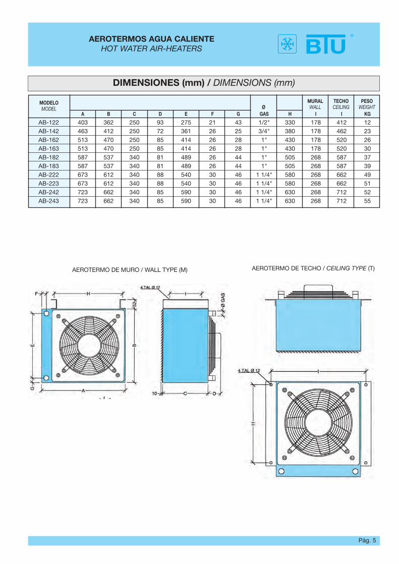
DIMENSIONES (mm) / DIMENSIONS (mm)
MODELOMODEL Ø
MURALWALL
TECHOCEILING
PESOWEIGHT
A B C D E F G GAS H I I KG
AB-122 403 362 250 93 275 21 43 1/2" 330 178 412 12AB-142 463 412 250 72 361 26 25 3/4" 380 178 462 23AB-162 513 470 250 85 414 26 28 1" 430 178 520 26AB-163 513 470 250 85 414 26 28 1" 430 178 520 30AB-182 587 537 340 81 489 26 44 1" 505 268 587 37AB-183 587 537 340 81 489 26 44 1" 505 268 587 39AB-222 673 612 340 88 540 30 46 1 1/4" 580 268 662 49AB-223 673 612 340 88 540 30 46 1 1/4" 580 268 662 51AB-242 723 662 340 85 590 30 46 1 1/4" 630 268 712 52AB-243 723 662 340 85 590 30 46 1 1/4" 630 268 712 55
AEROTERMO DE MURO / WALL TYPE (M) AEROTERMO DE TECHO / CEILING TYPE (T)
Pág. 6
AEROTERMOS AGUA FRÍACOLD WATER AIR-HEATERS
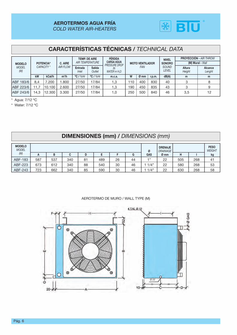
CARACTERÍSTICAS TÉCNICAS / TECHNICAL DATA
MODELOMODEL
(M)
POTENCIA*CAPACITY *
C. AIREAIR FLOW
TEMP. DE AIREAIR TEMPERATURE
PÉRDIDACARGA AGUA
PRESSURE DROP IN
WATER m H2O
MOTO VENTILADORFAN
NIVEL SONOROSOUND LEVEL
PROYECCIÓN - AIR THROW(M) Mural - Wall
Altura Height
AlcanceLenght
EntradaInlet
SalidaOutlet
kW kCal/h m3/h W Ø mm r.p.m. dB(A) m mºC / %Hr ºC / %Hr m.c.a.
ABF 183/6 8,4 7.200 1.800 27/50 17/84 1,3 110 400 830 40 3 8ABF 223/6 11,7 10.100 2.600 27/50 17/84 1,3 190 450 835 43 3 9ABF 243/6 14,3 12.300 3.300 27/50 17/84 1,0 250 500 840 46 3,5 12
* Agua: 7/12 ºC* Water: 7/12 ºC
DIMENSIONES (mm) / DIMENSIONS (mm)
MODELOMODEL
(M)Ø
GAS
DRENAJEDRAINAGE
Ø mm
PESOWEIGHT
A B C D E F G H I kg
ABF-183 587 537 340 81 489 26 44 1” 22 505 268 41ABF-223 673 612 340 88 540 30 46 1 1/4” 22 580 268 53ABF-243 723 662 340 85 590 30 46 1 1/4” 22 630 268 58
AEROTERMO DE MURO / WALL TYPE (M)
Ø 22
Pág. 7
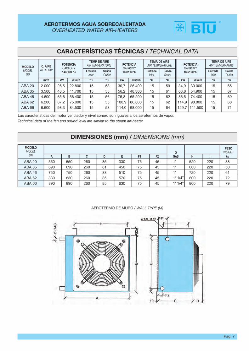
AEROTERMOS AGUA SOBRECALENTADAOVERHEATED WATER AIR-HEATERS
CARACTERÍSTICAS TÉCNICAS / TECHNICAL DATA
MODELOMODEL
(M)
C. AIREAIR FLOW
TEMP. DE AIREAIR TEMPERATUREPOTENCIA
CAPACITY140/100 ºC Entrada
InletSalidaOutlet
m3/h kW kCal/h ºC ºC
ABA 20 2.000 26,5 22.800 15 53 30,7 26.400 15 59 34,9 30.000 15 65ABA 35 3.500 48,5 41.700 15 55 56,2 48.300 15 61 63,8 54.900 15 67ABA 46 4.600 65,6 56.400 15 56 75,8 65.200 15 62 86,5 74.400 15 69ABA 62 6.200 87,2 75.000 15 55 100,9 86.800 15 62 114,9 98.800 15 68ABA 66 6.600 98,3 84.500 15 58 114,0 98.000 15 64 129,7 111.500 15 71
Las características del motor ventilador y nivel sonoro son iguales a los aerotermos de vapor.Technical data of the fan and sound level are similar to the steam air-heater.
kW kCal/h ºC ºC kW kCal/h ºC ºC
TEMP. DE AIREAIR TEMPERATUREPOTENCIA
CAPACITY160/110 ºC Entrada
InletSalidaOutlet
TEMP. DE AIREAIR TEMPERATUREPOTENCIA
CAPACITY180/120 ºC Entrada
InletSalidaOutlet
DIMENSIONES (mm) / DIMENSIONS (mm)
MODELOMODEL
(M)Ø
GAS
PESOWEIGHT
A B C D E F1 F2 H I kg
ABA 20 550 550 260 85 330 75 45 1" 520 220 38ABA 35 690 690 260 81 450 75 45 1" 660 220 50ABA 46 750 750 260 88 510 75 45 1" 720 220 61ABA 62 830 830 260 85 570 75 45 1" 800 220 72ABA 66 890 890 260 85 630 75 45 1" 860 220 79
AEROTERMO DE MURO / WALL TYPE (M)
1/4"1/4"
Pág. 8
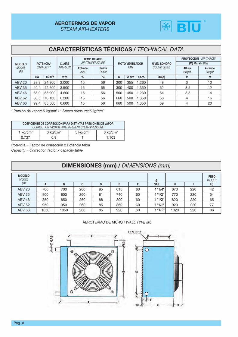
AEROTERMOS DE VAPORSTEAM AIR-HEATERS
CARACTERÍSTICAS TÉCNICAS / TECHNICAL DATA
MODELOMODEL
(M)
POTENCIA*CAPACITY *
C. AIREAIR FLOW
TEMP. DE AIREAIR TEMPERATURE MOTO VENTILADOR
FANNIVEL SONOROSOUND LEVEL
PROYECCIÓN - AIR THROW(M) Mural - Wall
Altura Height
AlcanceLenght
EntradaInlet
SalidaOutlet
kW kCal/h m3/h W Ø mm r.p.m. dB(A) m mºC ºC
ABV 20 28,3 24.300 2.000 15 56 200 355 1.260 48 3 10ABV 35 49,4 42.500 3.500 15 55 300 400 1.350 52 3,5 12ABV 46 65,0 55.900 4.600 15 56 500 450 1.230 54 3,5 14ABV 62 88,5 76.100 6.200 15 56 660 500 1.350 58 4 16ABV 66 99,4 85.500 6.600 15 58 660 500 1.350 59 4 20
* Presión de vapor: 5 kg/cm2 / * Steam pressure: 5 kg/cm2
COEFICIENTE DE CORRECCIÓN PARA DISTINTAS PRESIONES DE VAPORCORRECTION FACTOR FOR DIFFERENT STEAM PRESSURE
1 kg/cm2 3 kg/cm2 5 kg/cm2 8 kg/cm2
0,737 0,9 1 1,103
Potencia = Factor de corrección x Potencia tablaCapacity = Correction factor x capacity table
DIMENSIONES (mm) / DIMENSIONS (mm)
MODELOMODEL
(M)Ø
GAS
PESOWEIGHT
A B C D E F H I kg
ABV 20 700 700 260 85 615 60 1" 670 220 42ABV 35 800 800 260 81 740 60 1" 770 220 54ABV 46 850 850 260 88 800 60 1" 820 220 65ABV 62 950 950 260 85 860 60 1" 920 220 77ABV 66 1050 1050 260 85 920 60 1" 1020 220 86
AEROTERMO DE MURO / WALL TYPE (M)
1/4"1/2"1/2"1/2"1/2"
Pág. 9
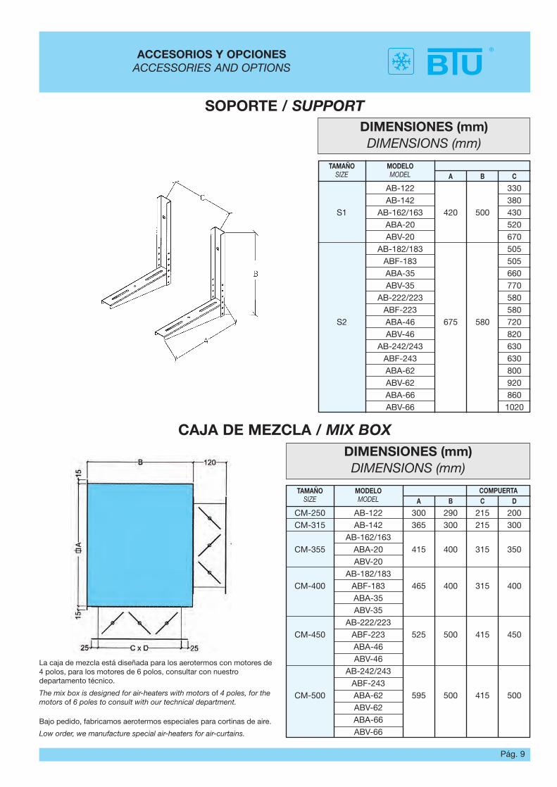
ACCESORIOS Y OPCIONESACCESSORIES AND OPTIONS
DIMENSIONES (mm)DIMENSIONS (mm)
MODELOMODEL
TAMAÑOSIZE
COMPUERTAA B C D
CM-250 AB-122 300 290 215 200CM-315 AB-142 365 300 215 300
AB-162/163CM-355 ABA-20 415 400 315 350
ABV-20AB-182/183
CM-400 ABF-183 465 400 315 400ABA-35ABV-35
AB-222/223CM-450 ABF-223 525 500 415 450
ABA-46ABV-46
AB-242/243ABF-243
CM-500 ABA-62 595 500 415 500ABV-62ABA-66ABV-66
DIMENSIONES (mm)DIMENSIONS (mm)
MODELOMODEL
TAMAÑOSIZE A B C
AB-122 330AB-142 380
S1 AB-162/163 420 500 430ABA-20 520ABV-20 670
AB-182/183 505ABF-183 505ABA-35 660ABV-35 770
AB-222/223 580ABF-223 580
S2 ABA-46 675 580 720ABV-46 820
AB-242/243 630ABF-243 630ABA-62 800ABV-62 920ABA-66 860ABV-66 1020
SOPORTE / SUPPORT
CAJA DE MEZCLA / MIX BOX
Bajo pedido, fabricamos aerotermos especiales para cortinas de aire.
Low order, we manufacture special air-heaters for air-curtains.
La caja de mezcla está diseñada para los aerotermos con motores de4 polos, para los motores de 6 polos, consultar con nuestrodepartamento técnico.
The mix box is designed for air-heaters with motors of 4 poles, for themotors of 6 poles to consult with our technical department.
Pág. 10
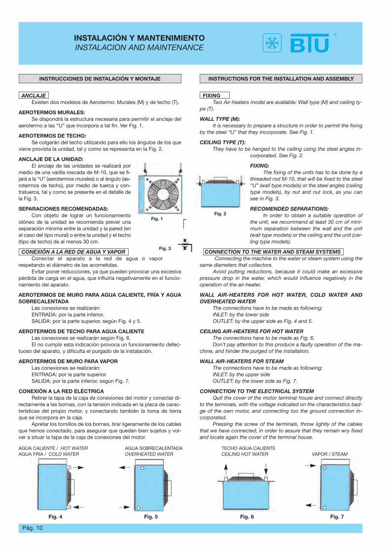
INSTALACIÓN Y MANTENIMIENTOINSTALACION AND MAINTENANCE
INSTRUCTIONS FOR THE INSTALLATION AND ASSEMBLY
FIXINGTwo Air-heaters model are available: Wall type (M) and ceiling ty-
pe (T).
WALL TYPE (M):It is necessary to prepare a structure in order to permit the fixing
by the steel “U” that they incorporate. See Fig. 1.
CEILING TYPE (T):They have to be hanged to the ceiling using the steel angles in-
corporated. See Fig. 2.
FIXING:The fixing of the units has to be done by a
threaded rod M-10, that will be fixed to the steel“U” (wall type models) or the steel angles (ceilingtype models), by nut and nut lock, as you cansee in Fig. 3.
RECOMENDED SEPARATIONS:In order to obtain a suitable operation of
the unit, we recommend at least 30 cm of mini-mum separation between the wall and the unit(wall type models) or the ceiling and the unit (cei-ling type models).
CONNECTION TO THE WATER AND STEAM SYSTEMSConnecting the machine to the water or steam system using the
same diameters that collectors.Avoid putting reductions, because it could make an excessive
pressure drop in the water, which would influence negatively in theoperation of the air-heater.
WALL AIR-HEATERS FOR HOT WATER, COLD WATER ANDOVERHEATED WATER
The connections have to be made as following:INLET: by the lower sideOUTLET: by the upper side as Fig. 4 and 5.
CEILING AIR-HEATERS FOR HOT WATERThe connections have to be made as Fig. 6.Don’t pay attention to this produce a faulty operation of the ma-
chine, and hinder the purged of the installation.
WALL AIR-HEATERS FOR STEAMThe connections have to be made as following:INLET: by the upper sideOUTLET: by the lower side as Fig. 7.
CONNECTION TO THE ELECTRICAL SYSTEMQuit the cover of the motor terminal house and connect directly
to the terminals, with the voltage indicated on the characteristics bad-ge of the own motor, and connecting too the ground connection in-corporated.
Pressing the screw of the terminals, throw lightly of the cablesthat we have connected, in order to assure that they remain wry fixedand locate again the cover of the terminal house.
INSTRUCCIONES DE INSTALACIÓN Y MONTAJE
ANCLAJEExisten dos modelos de Aerotermo: Murales (M) y de techo (T).
AEROTERMOS MURALES:Se dispondrá la estructura necesaria para permitir el anclaje del
aerotermo a las “U” que incorpora a tal fin. Ver Fig. 1.
AEROTERMOS DE TECHO:Se colgarán del techo utilizando para ello los ángulos de los que
viene provista la unidad, tal y como se representa en la Fig. 2.
ANCLAJE DE LA UNIDAD:El anclaje de las unidades se realizará por
medio de una varilla roscada de M-10, que se fi-jará a la “U” (aerotermos murales) o al ángulo (ae-rotermos de techo), por medio de tuerca y con-tratuerca, tal y como se presente en el detalle dela Fig. 3.
SEPARACIONES RECOMENDADAS:Con objeto de lograr un funcionamiento
idóneo de la unidad se recomienda prever unaseparación mínima entre la unidad y la pared (enel caso del tipo mural) o entre la unidad y el techo(tipo de techo) de al menos 30 cm.
CONEXIÓN A LA RED DE AGUA Y VAPOR Conectar el aparato a la red de agua o vapor
respetando el diámetro de las acometidas.Evitar poner reducciones, ya que pueden provocar una excesiva
pérdida de carga en el agua, que influiría negativamente en el funcio-namiento del aparato.
AEROTERMOS DE MURO PARA AGUA CALIENTE, FRÍA Y AGUASOBRECALENTADA
Las conexiones se realizarán:ENTRADA: por la parte inferior.SALIDA: por la parte superior, según Fig. 4 y 5.
AEROTERMOS DE TECHO PARA AGUA CALIENTE Las conexiones se realizarán según Fig. 6.El no cumplir esta indicación provoca un funcionamiento defec-
tuoso del aparato, y dificulta el purgado de la instalación.
AEROTERMOS DE MURO PARA VAPORLas conexiones se realizarán:ENTRADA: por la parte superior.SALIDA: por la parte inferior, según Fig. 7.
CONEXIÓN A LA RED ELÉCTRICARetirar la tapa de la caja de conexiones del motor y conectar di-
rectamente a las bornas, con la tensión indicada en la placa de carac-terísticas del propio motor, y conectando también la toma de tierraque se incorpora en la caja.
Apretar los tornillos de los bornes, tirar ligeramente de los cablesque hemos conectado, para asegurar que quedan bien sujetos y vol-ver a situar la tapa de la caja de conexiones del motor.
Fig. 1Fig. 2
Fig. 3
Fig. 4
AGUA CALIENTE / HOT WATERAGUA FRIA / COLD WATER
AGUA SOBRECALENTADA OVERHEATED WATER
TECHO AGUA CALIENTECEILING HOT WATER VAPOR / STEAM
Fig. 5 Fig. 6 Fig. 7
Pág. 11
INSTRUCCIONES PARA LA PUESTA EN MARCHAINSTRUCTIONS FOR THE STARTING
INSTRUCTIONS FOR THE STARTINGFeeding the air heater and make sure that leakages in any of the
connections don’t exits.Purging the installation before starting the fans.Making sure that the net voltage coincides with the specified on
the characteristics badge.Verifying that the grille incorporated allows a correct distribution
of the air, and otherwise move the blades until get it, keeping in mindthat they should not close in excess in order to permit a maximum useof the section for air passing.
It is possible that exit air bags in the installation, which will be go-ne accumulating in the leaving water collector, avoiding the correctfunction of the machine. It is recommendable to repeat the purgedoperation after 1/2 to 1 h working the air-heater.
In cold water air-heaters, it will be connected to the drainage tu-be, the pipe for exit of condensing.
MAINTENANCE INSTRUCTIONEvery year the coil and the fans have to be cleaned by compres-
sed air (at 8 atm as maximum).
NORMAL WORKING CONDITIONS.They are considered as normal the operation situations in those
that neither the temperature neither the humidity are extreme, as wellas the exempt environments of agents that attack to the materials as ithappens in saline, excessively sandy, etc.
The entrance of the water in the coil will be made to a maximumtemperature of 100 ºC and 180ºC for overheated water it supposedthat each coil is designed for the circulation of water in its interior, forwhat another fluid won't be used without the maker's previous autho-risation.
The work pressures will be of 8 Kg/cm2 as maximum for air-hea-ters of water and of 10 Kg/cm2 for steam air-heaters.
LIMITS OF THE WORKING CONDITIONSWhen the voltage of the installation differs more than 10% of the
nominal for the one the unit was designed, it is not guaranteed that themotor maintains the conditions for those that was selected, and ob-viously might be damaged.
RISK SITUATIONSBefore making any intervention in the unit it is necessary to cut
the electric feeding. The air-heaters incorporate axial fans that it constitutes a risk in
operation, because they rotate at high speeds, for what the manipula-tion of the unit is prohibited with the fan working.
ELIMINATION OR REDUCTION OF THE RISKSThe fan incorporates a protection grill. Nevertheless, to avoid
that the fan constitutes a danger a prudential time it will be expected,so that it stops before manipulating the unit.
Anyway the intervention of a professional will be demanded toavoid unnecessary risks.
The personnel that work with the unit will go provided of gloveslike a protection against the possible cuts that it could be caused.
RESIDUAL RISKSAlthough the air-heater is completely stopped, in heating season,
it is necessary to be careful when manipulating next to the connectionsof water or steam, because the burn risk exists if the pipes are tou-ched.
INSTRUCCIONES PARA LA PUESTA EN MARCHA.Alimentar el aerotermo y asegurarse que no existen fugas en nin-
guna de las conexiones.Purgar la instalación antes de poner en marcha los ventiladores.Asegurarse que la tensión en la red eléctrica coincide con la se-
ñalada en la placa de características.Verificar que la rejilla incorporada a la unidad permite una co-
rrecta distribución del aire, y en caso contrario colocar las lamas de larejilla de modo que se consiga una uniforme distribución del mismo,teniendo en cuenta que no deben cerrarse en exceso para permitir unmáximo aprovechamiento de la sección de paso del aire.
Es posible que en la instalación existan bolsas de aire que seirán acumulando en el colector de salida de agua, impidiendo un co-rrecto funcionamiento del aparato. Es recomendable repetir la opera-ción de purgado después de 1/2 a 1 h de funcionamiento del aeroter-mo.
En los aerotermos de agua fría se conectará al tubo de drenajela tubería de salida de condensados.
INSTRUCCIONES DE MANTENIMIENTO.Cada año se procederá a la limpieza de la batería y del ventila-
dor por medio de aire a presión (a 8 atm como máximo).
CONDICIONES NORMALES DE UTILIZACIÓN.Se consideran como normales las situaciones de funcionamien-
to en las que ni la temperatura ni la humedad son extremas, así comolos ambientes exentos de agentes que ataquen a los materiales comoocurre en ambientes salinos, excesivamente arenosos, etc.
La entrada del agua en la batería se hará a una temperatura má-xima de 100 ºC y 180 ºC para agua sobrecalentada y se entiende quela batería está concebida para la circulación de agua en su interior, porlo que no se deberá utilizar otro fluido sin previa autorización del fabri-cante.
Las presiones de trabajo serán de 8 Kg/cm2 como máximo paraaerotermos de agua y de 10 Kg/cm2 para aerotermos de vapor.
CONDICIONES DE FUNCIONAMIENTO LÍMITE.En instalaciones en las que la tensión difiera de más de un 10 %
de la tensión nominal para la que está diseñada la unidad, no se ga-rantiza que el motor mantenga las condiciones para las que se selec-cionó, y se entiende que se corre el peligro de avería.
SITUACIONES DE RIESGO.Antes de efectuar cualquier intervención en la unidad se cortará
la alimentación eléctrica.Los aerotermos incorporan ventiladores axiales, que en funcio-
namiento constituye un riesgo, ya que giran a velocidades altas, por loque se prohíbe la manipulación de la unidad con el ventilador funcio-nando.
ELIMINACIÓN O REDUCCIÓN DE LOS RIESGOS.El ventilador incorpora una rejilla de protección. No obstante,
para evitar que el ventilador constituya un peligro se esperará un tiem-po prudencial, para que se detenga antes de manipular la unidad.
En cualquier caso se exigirá la intervención de un profesional pa-ra evitar riesgos innecesarios.
El personal que entre en contacto con la unidad irá provisto deguantes como medio de protección contra los posibles cortes que pu-diera ocasionarse.
RIESGOS RESIDUALES.Aunque el aerotermo esté totalmente parado, en temporada de
calefacción, hay que tener cuidado al manipular junto a las acometi-das de agua o vapor, ya que existe riesgo de quemadura si se tocanlas tuberías.
R
- Código: BTU-6001. - Edición: Ene. 2014.- BTU se reserva el derecho a realizar modificaciones de sus productos sin previo aviso.- Este catálogo es propiedad de BTU y no podrá ser reproducido total o parcialmente, ni comunicado a terceros sin su expresa autorización.
OFICINAS: BTU CL. Ponferrada, 30 E-28947 - Fuenlabrada - MADRID - Tel. 91 400 97 60 / Fax 91 400 97 61http://www.btu.es e-mail: [email protected]
�
�
�
�
�
�
Baterías /
Ventiloconvectores /
Aerotermos /
Condensadores /
Evaporadores /
Aero-refrigeradores /
Coils
Fan-coils
Air-heaters
Condensers
Unit-coolers
Dry-coolers
DIN EN ISO 9001:2008Certificado nº 0.04.10236