Embed Size (px)
Citation preview
Aerospace Filtration Systems RFM Supplement For 4 Research Park Drive Bell Model 407 St. Charles, MO 63304-5685 Rotorcraft
AFS-BH407-IBF-FMS-KIT Page 1 of 13 FAA Approval Date: June 24 2010 Revision: D
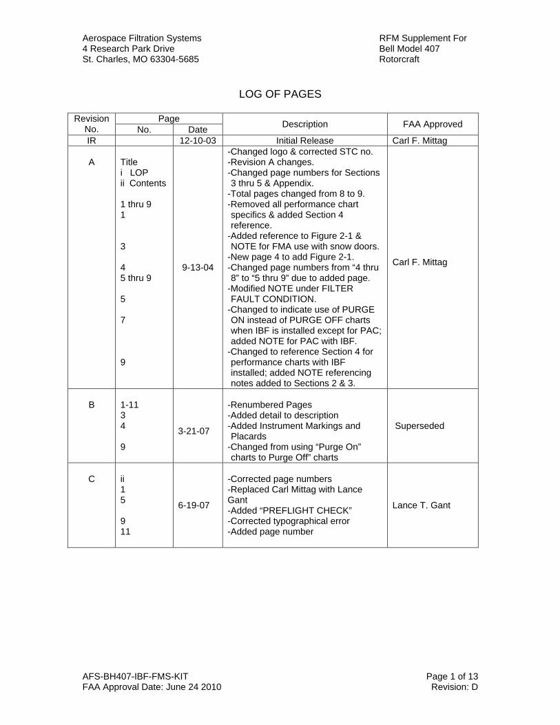
LOG OF PAGES
Revision
No. Page Description FAA Approved No. Date
IR 12-10-03 Initial Release Carl F. Mittag
A
Title i LOP ii Contents 1 thru 9 1 3 4 5 thru 9 5 7 9
9-13-04
-Changed logo & corrected STC no. -Revision A changes. -Changed page numbers for Sections 3 thru 5 & Appendix.
-Total pages changed from 8 to 9. -Removed all performance chart specifics & added Section 4 reference.
-Added reference to Figure 2-1 & NOTE for FMA use with snow doors.
-New page 4 to add Figure 2-1. -Changed page numbers from “4 thru 8” to “5 thru 9” due to added page.
-Modified NOTE under FILTER FAULT CONDITION.
-Changed to indicate use of PURGE ON instead of PURGE OFF charts when IBF is installed except for PAC; added NOTE for PAC with IBF.
-Changed to reference Section 4 for performance charts with IBF installed; added NOTE referencing notes added to Sections 2 & 3.
Carl F. Mittag
B
1-11 3 4 9
3-21-07
-Renumbered Pages -Added detail to description -Added Instrument Markings and Placards
-Changed from using “Purge On” charts to Purge Off” charts
Superseded
C
ii 1 5 9 11
6-19-07
-Corrected page numbers -Replaced Carl Mittag with Lance Gant -Added “PREFLIGHT CHECK” -Corrected typographical error -Added page number
Lance T. Gant
Aerospace Filtration Systems RFM Supplement For 4 Research Park Drive Bell Model 407 St. Charles, MO 63304-5685 Rotorcraft
AFS-BH407-IBF-FMS-KIT Page 3 of 13 FAA Approval Date: June 24 2010 Revision: D
TABLE OF CONTENTS
SECTION TITLE PAGE General Information 4 1 Limitations 5 2 Normal Procedures 6 3 Emergency/Malfunction Procedures 8 4 Performance 10 5 Weight and Balance 12 Appendix A Optional Equipment Supplements 13
Aerospace Filtration Systems RFM Supplement For 4 Research Park Drive Bell Model 407 St. Charles, MO 63304-5685 Rotorcraft
AFS-BH407-IBF-FMS-KIT Page 4 of 13 FAA Approval Date: June 24 2010 Revision: D
GENERAL INFORMATION
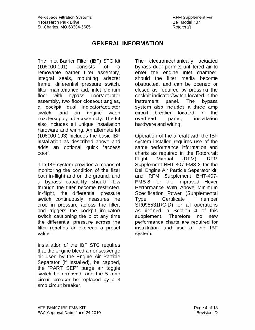
The Inlet Barrier Filter (IBF) STC kit (106000-101) consists of a removable barrier filter assembly, integral seals, mounting adapter frame, differential pressure switch, filter maintenance aid, inlet plenum floor with bypass door/actuator assembly, two floor closeout angles, a cockpit dual indicator/actuator switch, and an engine wash nozzle/supply tube assembly. The kit also includes all unique installation hardware and wiring. An alternate kit (106000-103) includes the basic IBF installation as described above and adds an optional quick “access door”. The IBF system provides a means of monitoring the condition of the filter both in-flight and on the ground, and a bypass capability should flow through the filter become restricted. In-flight, the differential pressure switch continuously measures the drop in pressure across the filter, and triggers the cockpit indicator/ switch cautioning the pilot any time the differential pressure across the filter reaches or exceeds a preset value. Installation of the IBF STC requires that the engine bleed air or scavenge air used by the Engine Air Particle Separator (if installed), be capped, the ”PART SEP” purge air toggle switch be removed, and the 5 amp circuit breaker be replaced by a 3 amp circuit breaker.
The electromechanically actuated bypass door permits unfiltered air to enter the engine inlet chamber, should the filter media become obstructed, and can be opened or closed as required by pressing the cockpit indicator/switch located in the instrument panel. The bypass system also includes a three amp circuit breaker located in the overhead panel, installation hardware and wiring. Operation of the aircraft with the IBF system installed requires use of the same performance information and charts as required in the Rotorcraft Flight Manual (RFM), RFM Supplement BHT-407-FMS-3 for the Bell Engine Air Particle Separator kit, and RFM Supplement BHT-407-FMS-8 for the Improved Hover Performance With Above Minimum Specification Power (Supplemental Type Certificate number SR095531RC-D) for all operations as defined in Section 4 of this supplement. Therefore no new performance charts are required for installation and use of the IBF system.
Aerospace Filtration Systems RFM Supplement For 4 Research Park Drive Bell Model 407 St. Charles, MO 63304-5685 Rotorcraft
AFS-BH407-IBF-FMS-KIT Page 5 of 13 FAA Approval Date: June 24 2010 Revision: D
INSTRUMENT MARKINGS AND PLACARDS
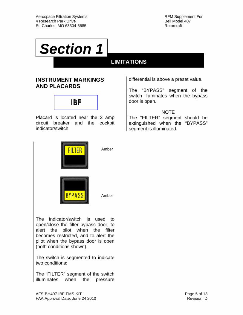
Placard is located near the 3 amp circuit breaker and the cockpit indicator/switch.
The indicator/switch is used to open/close the filter bypass door, to alert the pilot when the filter becomes restricted, and to alert the pilot when the bypass door is open (both conditions shown). The switch is segmented to indicate two conditions: The “FILTER” segment of the switch illuminates when the pressure
differential is above a preset value. The “BYPASS” segment of the switch illuminates when the bypass door is open.
NOTE The “FILTER” segment should be extinguished when the “BYPASS” segment is illuminated.
LIMITATIONS
Section 1
Amber
Amber
Aerospace Filtration Systems RFM Supplement For 4 Research Park Drive Bell Model 407 St. Charles, MO 63304-5685 Rotorcraft
AFS-BH407-IBF-FMS-KIT Page 6 of 13 FAA Approval Date: June 24 2010 Revision: D
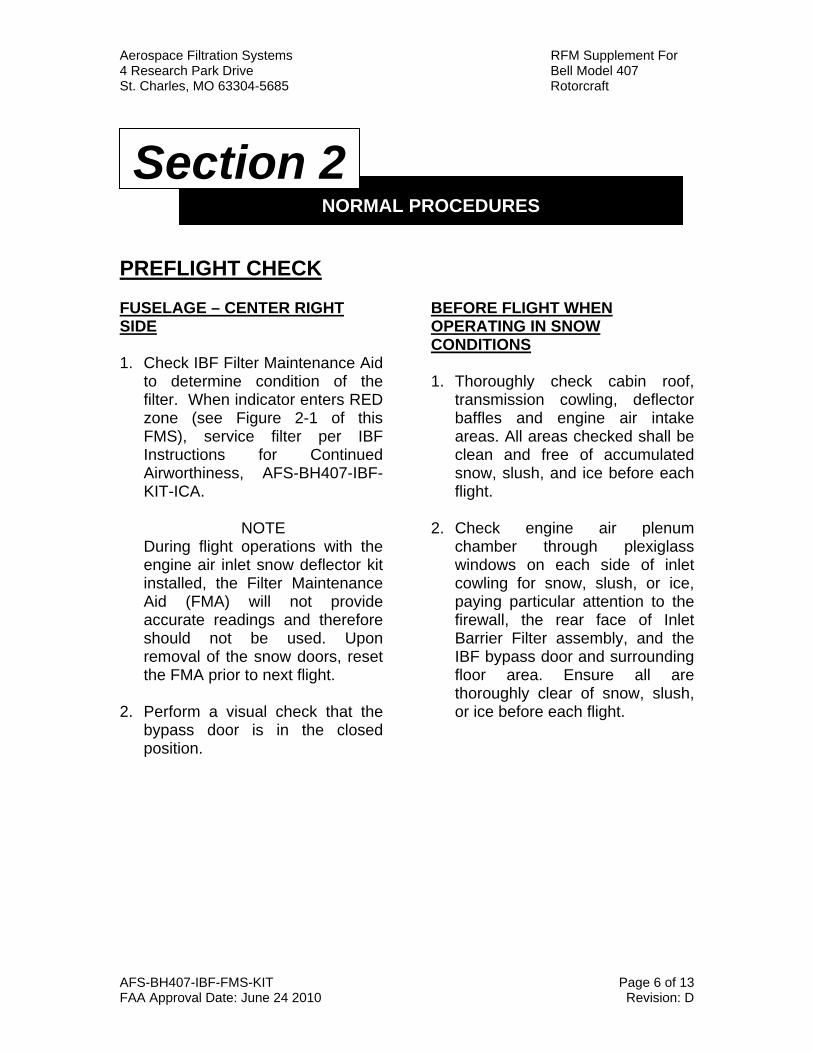
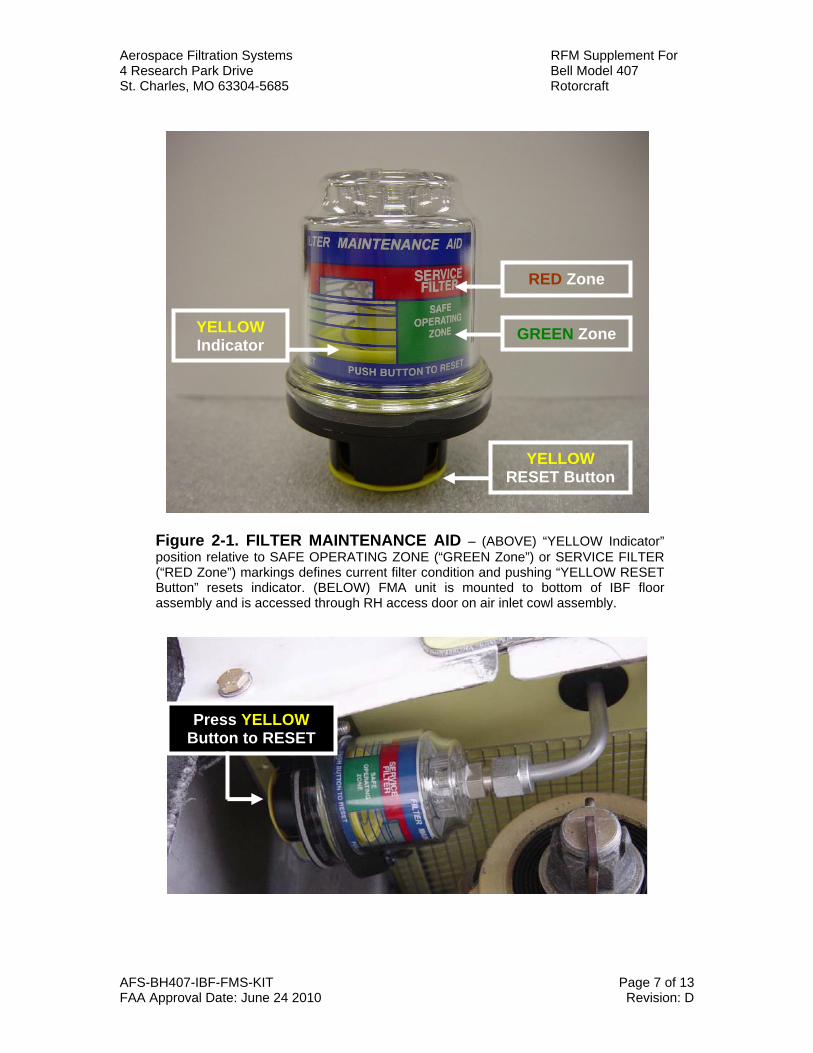
PREFLIGHT CHECK FUSELAGE – CENTER RIGHT SIDE 1. Check IBF Filter Maintenance Aid
to determine condition of the filter. When indicator enters RED zone (see Figure 2-1 of this FMS), service filter per IBF Instructions for Continued Airworthiness, AFS-BH407-IBF-KIT-ICA.
NOTE
During flight operations with the engine air inlet snow deflector kit installed, the Filter Maintenance Aid (FMA) will not provide accurate readings and therefore should not be used. Upon removal of the snow doors, reset the FMA prior to next flight.
2. Perform a visual check that the
bypass door is in the closed position.
BEFORE FLIGHT WHEN OPERATING IN SNOW CONDITIONS 1. Thoroughly check cabin roof,
transmission cowling, deflector baffles and engine air intake areas. All areas checked shall be clean and free of accumulated snow, slush, and ice before each flight.
2. Check engine air plenum
chamber through plexiglass windows on each side of inlet cowling for snow, slush, or ice, paying particular attention to the firewall, the rear face of Inlet Barrier Filter assembly, and the IBF bypass door and surrounding floor area. Ensure all are thoroughly clear of snow, slush, or ice before each flight.
NORMAL PROCEDURES
Section 2
Aerospace Filtration Systems RFM Supplement For 4 Research Park Drive Bell Model 407 St. Charles, MO 63304-5685 Rotorcraft
AFS-BH407-IBF-FMS-KIT Page 7 of 13 FAA Approval Date: June 24 2010 Revision: D
Figure 2-1. FILTER MAINTENANCE AID – (ABOVE) “YELLOW Indicator” position relative to SAFE OPERATING ZONE (“GREEN Zone”) or SERVICE FILTER (“RED Zone”) markings defines current filter condition and pushing “YELLOW RESET Button” resets indicator. (BELOW) FMA unit is mounted to bottom of IBF floor assembly and is accessed through RH access door on air inlet cowl assembly.
RED Zone
GREEN Zone YELLOW Indicator
GREEN Zone
YELLOW RESET Button
RED Zone
YELLOW Indicator
Press YELLOW Button to RESET
Aerospace Filtration Systems RFM Supplement For 4 Research Park Drive Bell Model 407 St. Charles, MO 63304-5685 Rotorcraft
AFS-BH407-IBF-FMS-KIT Page 8 of 13 FAA Approval Date: June 24 2010 Revision: D
Caution lights (amber)
PANEL WORDING FAULT CONDITION CORRECTIVE ACTION
FILTER (amber)
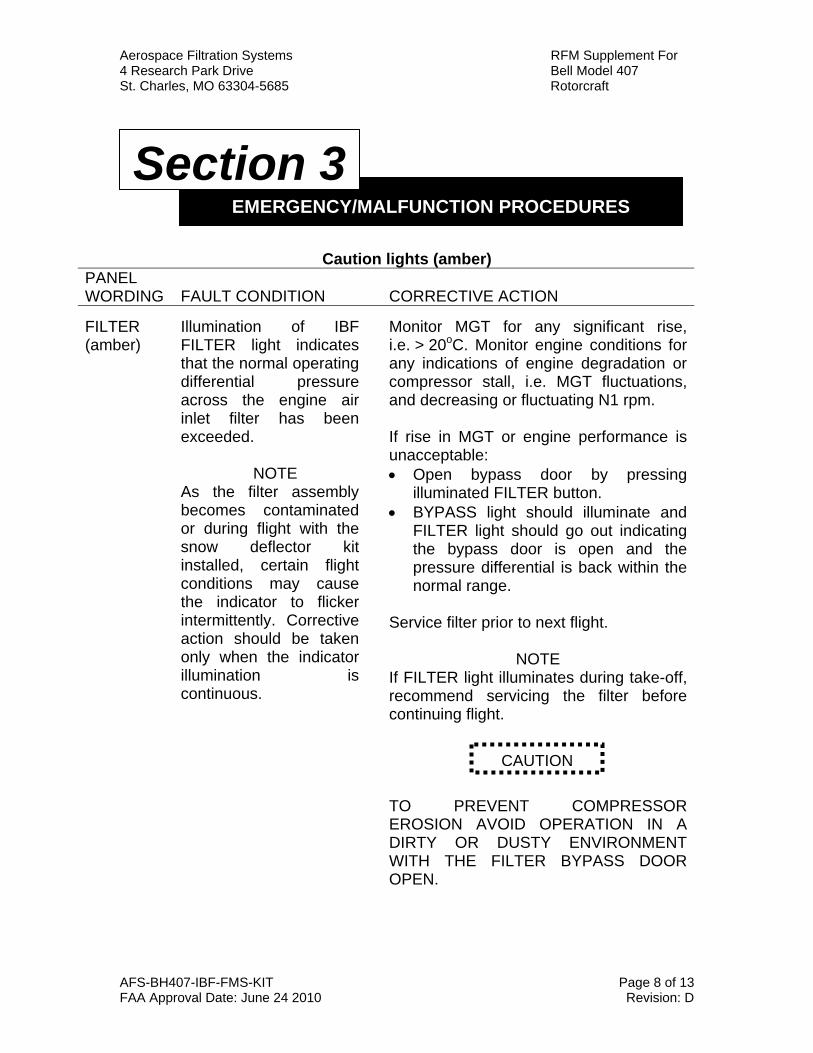
Illumination of IBF FILTER light indicates that the normal operating differential pressure across the engine air inlet filter has been exceeded.
NOTE As the filter assembly becomes contaminated or during flight with the snow deflector kit installed, certain flight conditions may cause the indicator to flicker intermittently. Corrective action should be taken only when the indicator illumination is continuous.
Monitor MGT for any significant rise, i.e. > 20oC. Monitor engine conditions for any indications of engine degradation or compressor stall, i.e. MGT fluctuations, and decreasing or fluctuating N1 rpm.
If rise in MGT or engine performance is unacceptable: • Open bypass door by pressing
illuminated FILTER button. • BYPASS light should illuminate and
FILTER light should go out indicating the bypass door is open and the pressure differential is back within the normal range.
Service filter prior to next flight.
NOTE If FILTER light illuminates during take-off, recommend servicing the filter before continuing flight. TO PREVENT COMPRESSOR EROSION AVOID OPERATION IN A DIRTY OR DUSTY ENVIRONMENT WITH THE FILTER BYPASS DOOR OPEN.
CAUTION
EMERGENCY/MALFUNCTION PROCEDURES
Section 3
Aerospace Filtration Systems RFM Supplement For 4 Research Park Drive Bell Model 407 St. Charles, MO 63304-5685 Rotorcraft
AFS-BH407-IBF-FMS-KIT Page 9 of 13 FAA Approval Date: June 24 2010 Revision: D
“BYPASS”
The bypass door is open and the filter is being bypassed with unfiltered air entering the engine. Inadvertent encounters with icing.
If the flight or landing environment has significant dirt or debris, it is recommended that the bypass door be closed, provided no rotorcraft or engine limits will be exceeded. With the bypass closed, the “BYPASS’ segment will extinguish and the “FILTER” segment will potentially re-appear under high engine power settings until the filter has been cleaned. Exit condition as soon as practical.
Aerospace Filtration Systems RFM Supplement For 4 Research Park Drive Bell Model 407 St. Charles, MO 63304-5685 Rotorcraft
AFS-BH407-IBF-FMS-KIT Page 10 of 13 FAA Approval Date: June 24 2010 Revision: D
OPERATIONS WITH STANDARD BELL 407 CONFIGURATION
When the Inlet Barrier Filter (IBF) system STC is installed, use the basic inlet Power Assurance Check (PAC) chart (hover or level flight) contained in the basic RFM to determine engine health. If the PAC is satisfactory then basic performance can be obtained and the basic inlet performance data charts are applicable. If the basic PAC is not satisfactory then published performance may not be achieved. If this is the case, either clean the IBF filter and recheck the engine health using the basic inlet PAC chart, or compare the recorded PAC values against the Engine Air Particle Separator (EAPS) chart located in the Particle Separator supplement (BHT-407-FMS-3). If engine health is found to be satisfactory using the EAPS PAC chart, then the EAPS performance can be obtained and the EAPS performance data charts are applicable. If the engine health is not satisfactory, then clean the filter and conduct another PAC check, and compare the results to the basic inlet PAC chart or the EAPS PAC chart. If the recorded PAC results after cleaning the filters are still not
satisfactory, then contact maintenance for troubleshooting. The frequency at which PAC’s are conducted is up to the discretion of the operator based on the operating environment, (i.e. temperature, altitude, airborne contaminate) and the requirements of the Flight Manual.
OPERATIONS WITH IMPROVED HOVER PERFORMANCE STC
CONFIGURATION (STC No. SR095531RC-D)
When operating with the Improved Hover Performance With Above Minimum Specification Power STC (Plus Power) installed, use of the procedures and data found in the FAA approved FMS are applicable (BHT-407-FMS-8).
NOTE All requirements, as outlined in BHT-407-FMS-8 apply with the IBF installed and must be adhered to. Use the basic inlet “Plus Power” PAC chart to determine engine health with the average of the 10 most recent PAC events. If the basic inlet “Plus Power” PAC is satisfactory, then performance can be achieved using the appropriate
PERFORMANCE
Section 4
Aerospace Filtration Systems RFM Supplement For 4 Research Park Drive Bell Model 407 St. Charles, MO 63304-5685 Rotorcraft
AFS-BH407-IBF-FMS-KIT Page 11 of 13 FAA Approval Date: June 24 2010 Revision: D
performance charts in BHT-407-FMS-8. If the basic inlet “Plus Power” PAC is not satisfactory (i.e. “Plus Power” margin is 2.0% or more lower than the average of the last 10 PAC values), then basic inlet “Plus Power” published performance may not be achieved. If this is the case, either clean the IBF filter and recheck the engine health using the basic inlet BHT-407-FMS-8 PAC chart, or compare the recorded PAC values against the EAPS PAC chart located in FMS BHT-407-FMS-8. If the EAPS “Plus Power” PAC is satisfactory, performance can be achieved using the EAPS performance charts in FMS BHT-407-FMS-8. If the EAPS “Plus Power” PAC is not satisfactory (i.e. “Plus Power” margin is 2.0% or more lower than the average of the last 10 PAC values), then EAPS “Plus Power” published performance may not be achieved. If this is the case, either clean the IBF filter and recheck the engine health using FMS BHT-407-FMS-8 PAC charts (basic inlet or EAPS), or compare PAC values using the standard Bell 407 configuration procedures as outlined in the “Operations With Standard Bell 407 Configuration” section of this manual listed above. In order to use the Improved Hover Performance With Above Minimum Specification Power performance charts, Power Assurance Checks must be conducted daily per the FMS.
NOTE Use of performance charts presented in FMS BHT-407-FMS-8 is not authorized with Snow Deflector Kit (BHT-407-FMS-4) installed.
ALL CONFIGURATIONS
Helicopter performance is reduced as the IBF becomes contaminated with dirt, dust and debris. The pilot/operator is responsible to utilize the PAC procedure to determine if the engine can produce installed power. If engine does not pass PAC, published performance cannot be achieved. Contact maintenance for appropriate trouble shooting procedures as outlined in applicable Instructions for Continued Airworthiness or Maintenance Manuals. Ensure that the IBF FILTER caution light is not illuminated during performance of the PAC.
CAUTION
Aerospace Filtration Systems RFM Supplement For 4 Research Park Drive Bell Model 407 St. Charles, MO 63304-5685 Rotorcraft
AFS-BH407-IBF-FMS-KIT Page 12 of 13 FAA Approval Date: June 24 2010 Revision: D
No change.
WEIGHT AND BALANCE
Section 5
Aerospace Filtration Systems RFM Supplement For 4 Research Park Drive Bell Model 407 St. Charles, MO 63304-5685 Rotorcraft
AFS-BH407-IBF-FMS-KIT Page 13 of 13 FAA Approval Date: June 24 2010 Revision: D
OPERATIONS WITH STANDARD BELL 407 CONFIGURATION
Operation of the aircraft with the IBF system installed requires use of the same performance information and / or charts as required in the Rotorcraft Flight Manual, and FMS BHT-407-FMS-3 for the Bell EAPS kit for all operations as defined in Section 4 of this supplement. Therefore no new performance charts are required.
NOTE During flight operations with the engine air inlet snow deflector kit installed, see notes in Section 2 of this supplement relating to use of the IBF Filter Maintenance Aid, and in Section 3 of this supplement relating to intermittent FILTER light indications.
OPERATIONS WITH IMPROVED HOVER PERFORMANCE STC
CONFIGURATION (STC No. SR095531RC-D)
Operation of the aircraft with the IBF system installed and in accordance with the performance charts contained in FMS BHT-407-FMS-8 requires that the Improved Hover Performance With Above Minimum Specification Power STC be installed
on the aircraft. In this configuration, operations shall be conducted in accordance with Section 4 of this supplement. Performance charts are provided in BHT-407-FMS-8 for those operators who have the STC installed. Additional performance charts are contained in the basic RFM and FMS BHT-407-FMS-3.
NOTE Use of performance charts presented in FMS BHT-407-FMS-8 is not authorized with Snow Deflector Kit (BHT-407-FMS-4) installed.
OPTIONAL EQUIPMENT SUPPLEMENTS
Appendix A