Embed Size (px)
Citation preview
AEROSPACE DIMENSIONS (REVIEW, AIRCRAFT SYSTEMS/AIRPORTS,
MODULE 2)
CAPTAIN. JERRY PAINTER AEROSPACE EDUCATION OFFICER
COMPOSITE SQUADRON 316, (CIVIL AIR PATROL)
CASA GRANDE, ARIZONA
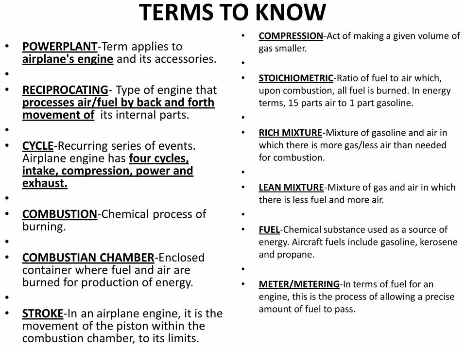
TERMS TO KNOW • COMPRESSION-Act of making a given volume of
gas smaller.
•
• STOICHIOMETRIC-Ratio of fuel to air which, upon combustion, all fuel is burned. In energy terms, 15 parts air to 1 part gasoline.
•
• RICH MIXTURE-Mixture of gasoline and air in which there is more gas/less air than needed for combustion.
•
• LEAN MIXTURE-Mixture of gas and air in which there is less fuel and more air.
•
• FUEL-Chemical substance used as a source of energy. Aircraft fuels include gasoline, kerosene and propane.
•
• METER/METERING-In terms of fuel for an engine, this is the process of allowing a precise amount of fuel to pass.
• POWERPLANT-Term applies to airplane's engine and its accessories.
• • RECIPROCATING- Type of engine that
processes air/fuel by back and forth movement of its internal parts.
• • CYCLE-Recurring series of events.
Airplane engine has four cycles, intake, compression, power and exhaust.
• • COMBUSTION-Chemical process of
burning. • • COMBUSTIAN CHAMBER-Enclosed
container where fuel and air are burned for production of energy.
• • STROKE-In an airplane engine, it is the
movement of the piston within the combustion chamber, to its limits.
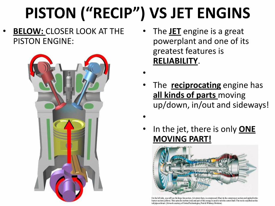
PISTON (“RECIP”) VS JET ENGINS • BELOW: CLOSER LOOK AT THE
PISTON ENGINE: • The JET engine is a great
powerplant and one of its greatest features is RELIABILITY.
•
• The reciprocating engine has all kinds of parts moving up/down, in/out and sideways!
•
• In the jet, there is only ONE MOVING PART!
PISTON ENGINE • Module One discussed the propeller and
how it works, like a rotating wing "lifting" forward.
•
• The airplane's engine provides power to the propeller and this combination provides “thrust”.
•
• It’s called a POWERPLANT when a portion of its energy is used to run other accessories, like the
• electrical system, cockpit heat and air-conditioning.
• Every internal combustion engine must have certain parts to change heat into mechanical energy.
•
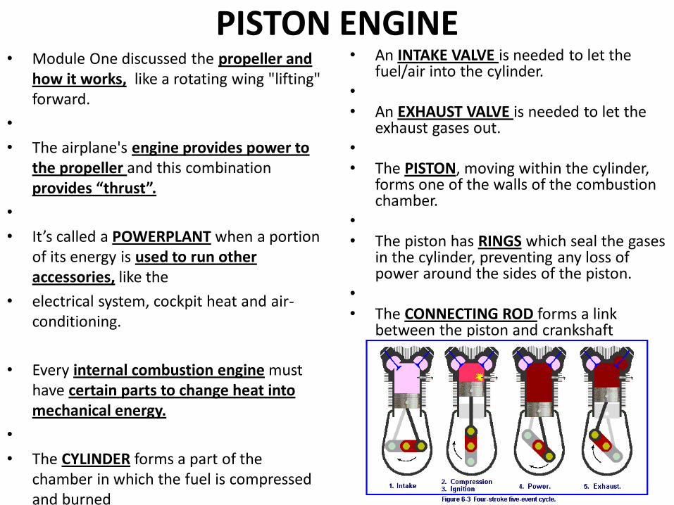
• The CYLINDER forms a part of the chamber in which the fuel is compressed and burned
• An INTAKE VALVE is needed to let the fuel/air into the cylinder.
• • An EXHAUST VALVE is needed to let the
exhaust gases out. • • The PISTON, moving within the cylinder,
forms one of the walls of the combustion chamber.
• • The piston has RINGS which seal the gases
in the cylinder, preventing any loss of power around the sides of the piston.
• • The CONNECTING ROD forms a link
between the piston and crankshaft
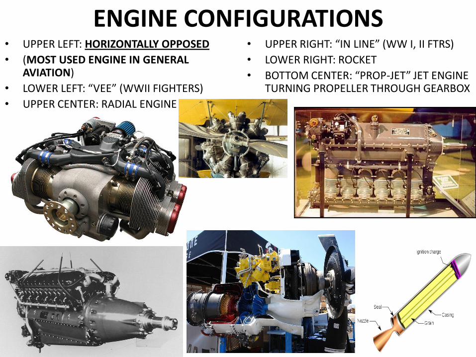
ENGINE CONFIGURATIONS • UPPER LEFT: HORIZONTALLY OPPOSED
• (MOST USED ENGINE IN GENERAL AVIATION)
• LOWER LEFT: “VEE” (WWII FIGHTERS)
• UPPER CENTER: RADIAL ENGINE
• UPPER RIGHT: “IN LINE” (WW I, II FTRS)
• LOWER RIGHT: ROCKET
• BOTTOM CENTER: “PROP-JET” JET ENGINE TURNING PROPELLER THROUGH GEARBOX
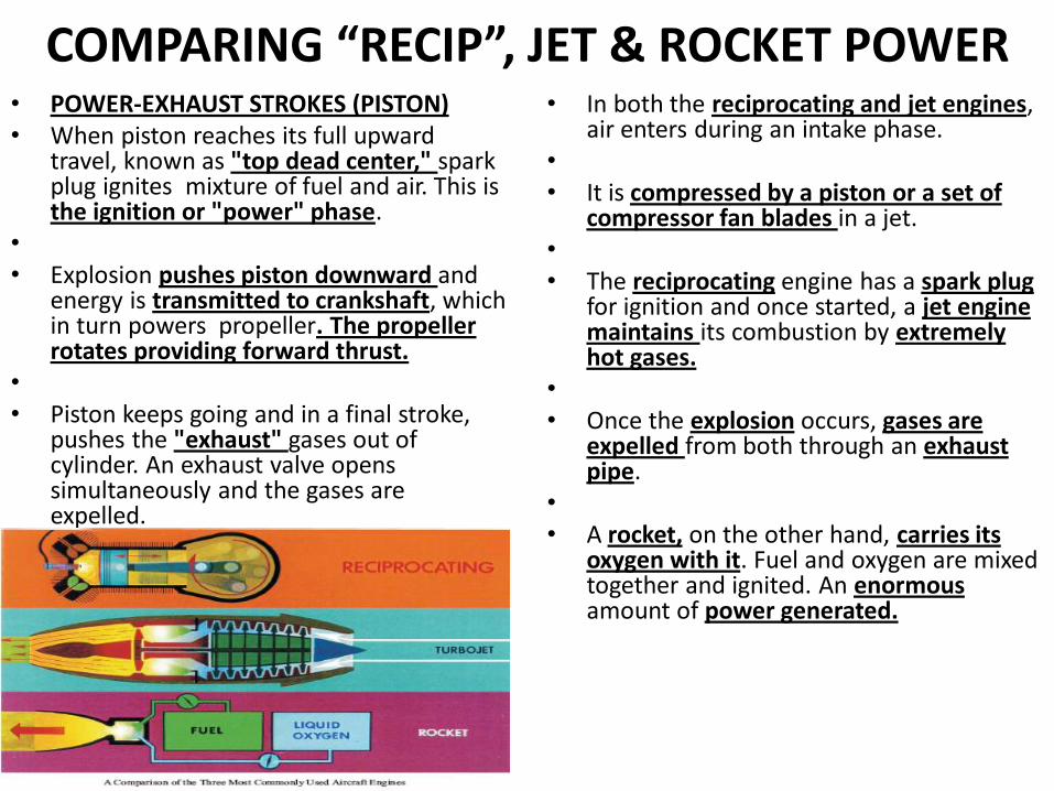
COMPARING “RECIP”, JET & ROCKET POWER • POWER-EXHAUST STROKES (PISTON) • When piston reaches its full upward
travel, known as "top dead center," spark plug ignites mixture of fuel and air. This is the ignition or "power" phase.
• • Explosion pushes piston downward and
energy is transmitted to crankshaft, which in turn powers propeller. The propeller rotates providing forward thrust.
• • Piston keeps going and in a final stroke,
pushes the "exhaust" gases out of cylinder. An exhaust valve opens simultaneously and the gases are expelled.
• In both the reciprocating and jet engines, air enters during an intake phase.
• • It is compressed by a piston or a set of
compressor fan blades in a jet. • • The reciprocating engine has a spark plug
for ignition and once started, a jet engine maintains its combustion by extremely hot gases.
• • Once the explosion occurs, gases are
expelled from both through an exhaust pipe.
• • A rocket, on the other hand, carries its
oxygen with it. Fuel and oxygen are mixed together and ignited. An enormous amount of power generated.
POWER • Converts heat energy into mechanical energy
and this mechanical energy turns the propeller. • • Millions of years ago, the Sun provided energy
to billions of plants and prehistoric animals and over time, their remains have been converted into what we now call "fossil fuels."
• • When refined into gasoline, it becomes source
of energy for airplane engines. • • Mixture occurs when two chemical compounds
come together, yet not chemically combined. Gasoline/air are in carburetor, but don't chemically combine until inside the cylinder.
• Air molecules do not become part of gasoline molecules until they are burned.
• When ignited, a chemical reaction, known as oxidation occurs and energy is produced that drives propellers and jet turbines.
• After this combustion occurs, gasoline molecules are converted into compounds like carbon monoxide, carbon dioxide, and water, then expelled as exhaust.
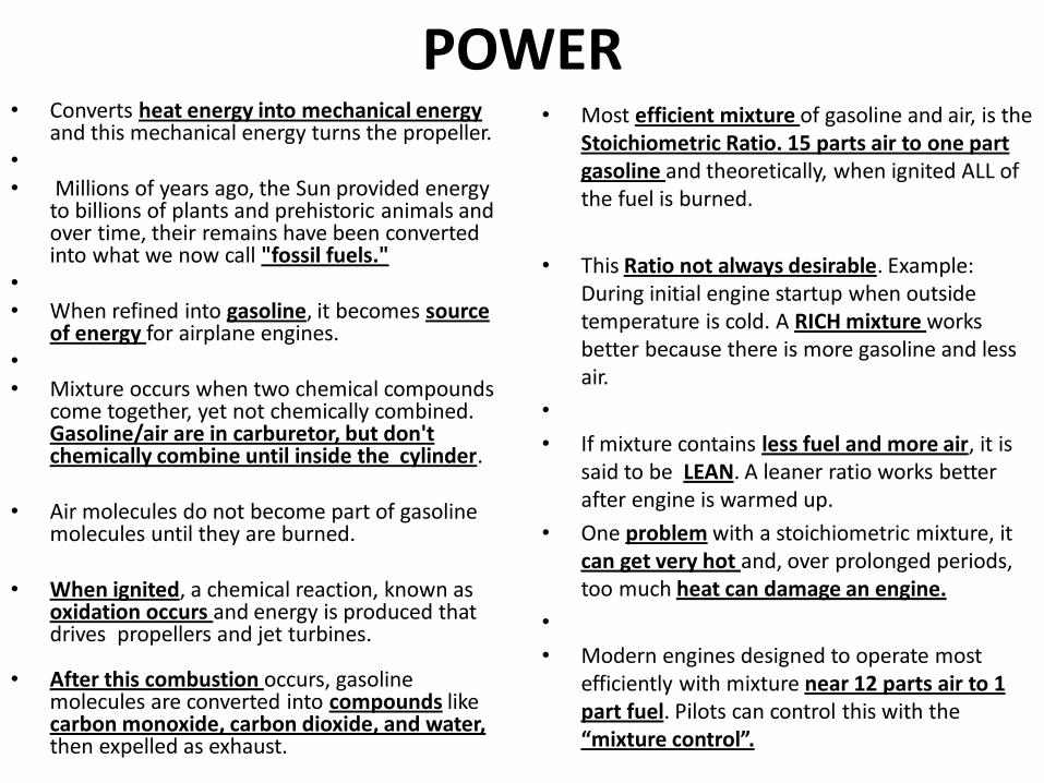
• Most efficient mixture of gasoline and air, is the Stoichiometric Ratio. 15 parts air to one part gasoline and theoretically, when ignited ALL of the fuel is burned.
• This Ratio not always desirable. Example: During initial engine startup when outside temperature is cold. A RICH mixture works better because there is more gasoline and less air.
•
• If mixture contains less fuel and more air, it is said to be LEAN. A leaner ratio works better after engine is warmed up.
• One problem with a stoichiometric mixture, it can get very hot and, over prolonged periods, too much heat can damage an engine.
•
• Modern engines designed to operate most efficiently with mixture near 12 parts air to 1 part fuel. Pilots can control this with the “mixture control”.
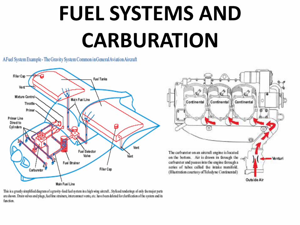
FUEL SYSTEMS AND CARBURATION
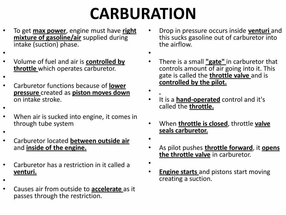
CARBURATION • To get max power, engine must have right
mixture of gasoline/air supplied during intake (suction) phase.
• • Volume of fuel and air is controlled by
throttle which operates carburetor. • • Carburetor functions because of lower
pressure created as piston moves down on intake stroke.
• • When air is sucked into engine, it comes in
through tube system • • Carburetor located between outside air
and inside of the engine.
• Carburetor has a restriction in it called a venturi.
• • Causes air from outside to accelerate as it
passes through the restriction.
• Drop in pressure occurs inside venturi and this sucks gasoline out of carburetor into the airflow.
• • There is a small "gate" in carburetor that
controls amount of air going into it. This gate is called the throttle valve and is controlled by the pilot.
• • It is a hand-operated control and it's
called the throttle.
• When throttle is closed, throttle valve seals carburetor.
• • As pilot pushes throttle forward, it opens
the throttle valve in carburetor. • • Engine starts and pistons start moving
creating a suction.
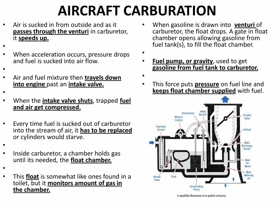
AIRCRAFT CARBURATION • Air is sucked in from outside and as it
passes through the venturi in carburetor, it speeds up.
• • When acceleration occurs, pressure drops
and fuel is sucked into air flow. • • Air and fuel mixture then travels down
into engine past an intake valve. • • When the intake valve shuts, trapped fuel
and air get compressed.
• Every time fuel is sucked out of carburetor into the stream of air, it has to be replaced or cylinders would starve.
• • Inside carburetor, a chamber holds gas
until its needed, the float chamber. • • This float is somewhat like ones found in a
toilet, but it monitors amount of gas in the chamber.
• When gasoline is drawn into venturi of carburetor, the float drops. A gate in float chamber opens allowing gasoline from fuel tank(s), to fill the float chamber.
• • Fuel pump, or gravity, used to get
gasoline from fuel tank to carburetor. • • This force puts pressure on fuel line and
keeps float chamber supplied with fuel.
CARBURATOR HEAT • Very important component in
carburetor "system" known as “carburetor heat”.
• • Under certain flying conditions, air
passing into carburetor will form ice in the venturi.
• This can be dangerous as it can make the carburetor inoperative.
• • If icing chokes carburetor, the engine
will quit!
• Pilots are taught how to use carburetor heat control so that it melts the ice.
• • Carburetor heat made available by
using the hot air surrounding the exhaust system.
• As pilot pulls carburetor heat control, heated air is channeled into the carburetor.
• • This closes off normal filtered air,
directing exhaust-heated, unfiltered air into carburetor.
• As hot air goes through carburetor, any ice is melted and the water passes through engine.
• • Momentarily, this creates a problem
because hot air is less dense than cold air.
• • Engine will run rough due to a fuel/air
mixture too rich. After ice is removed, pilot procedure is to close carburetor heat and return to colder air.
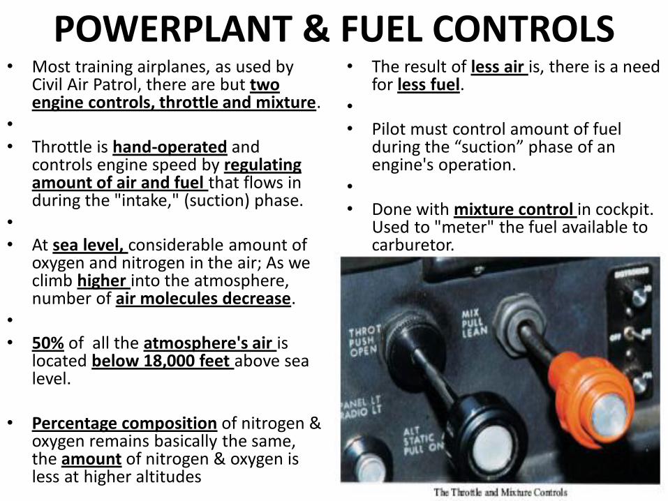
POWERPLANT & FUEL CONTROLS • Most training airplanes, as used by
Civil Air Patrol, there are but two engine controls, throttle and mixture.
• • Throttle is hand-operated and
controls engine speed by regulating amount of air and fuel that flows in during the "intake," (suction) phase.
• • At sea level, considerable amount of
oxygen and nitrogen in the air; As we climb higher into the atmosphere, number of air molecules decrease.
• • 50% of all the atmosphere's air is
located below 18,000 feet above sea level.
• Percentage composition of nitrogen & oxygen remains basically the same, the amount of nitrogen & oxygen is less at higher altitudes
• The result of less air is, there is a need for less fuel.
• • Pilot must control amount of fuel
during the “suction” phase of an engine's operation.
• • Done with mixture control in cockpit.
Used to "meter" the fuel available to carburetor.
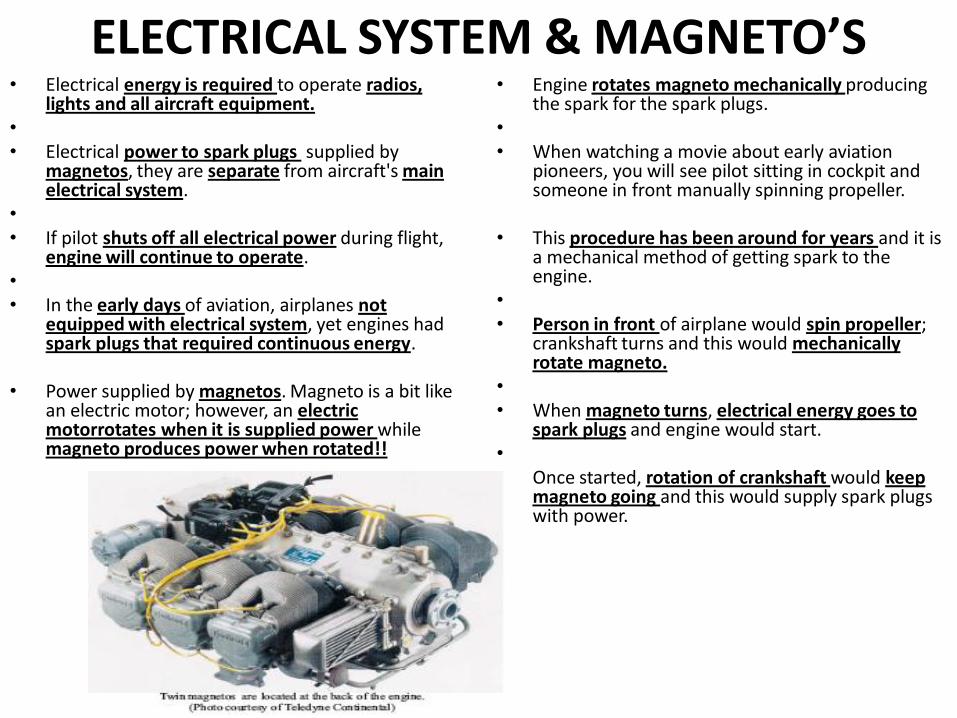
ELECTRICAL SYSTEM & MAGNETO’S • Electrical energy is required to operate radios,
lights and all aircraft equipment. • • Electrical power to spark plugs supplied by
magnetos, they are separate from aircraft's main electrical system.
• • If pilot shuts off all electrical power during flight,
engine will continue to operate. • • In the early days of aviation, airplanes not
equipped with electrical system, yet engines had spark plugs that required continuous energy.
• Power supplied by magnetos. Magneto is a bit like an electric motor; however, an electric motorrotates when it is supplied power while magneto produces power when rotated!!
• Engine rotates magneto mechanically producing the spark for the spark plugs.
• • When watching a movie about early aviation
pioneers, you will see pilot sitting in cockpit and someone in front manually spinning propeller.
• This procedure has been around for years and it is a mechanical method of getting spark to the engine.
• • Person in front of airplane would spin propeller;
crankshaft turns and this would mechanically rotate magneto.
• • When magneto turns, electrical energy goes to
spark plugs and engine would start. • • Once started, rotation of crankshaft would keep
magneto going and this would supply spark plugs with power.
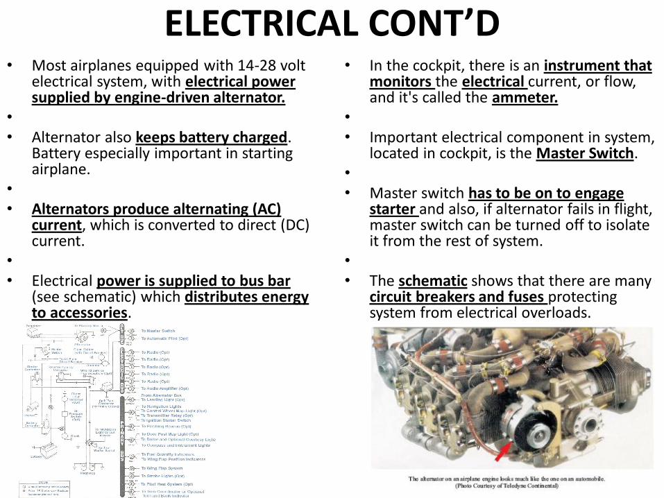
ELECTRICAL CONT’D • Most airplanes equipped with 14-28 volt
electrical system, with electrical power supplied by engine-driven alternator.
• • Alternator also keeps battery charged.
Battery especially important in starting airplane.
• • Alternators produce alternating (AC)
current, which is converted to direct (DC) current.
• • Electrical power is supplied to bus bar
(see schematic) which distributes energy to accessories.
• In the cockpit, there is an instrument that monitors the electrical current, or flow, and it's called the ammeter.
• • Important electrical component in system,
located in cockpit, is the Master Switch. • • Master switch has to be on to engage
starter and also, if alternator fails in flight, master switch can be turned off to isolate it from the rest of system.
• • The schematic shows that there are many
circuit breakers and fuses protecting system from electrical overloads.
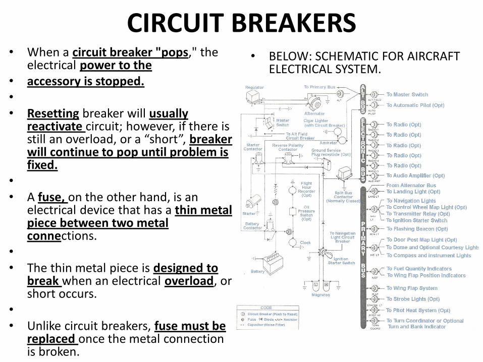
CIRCUIT BREAKERS • When a circuit breaker "pops," the
electrical power to the • accessory is stopped. • • Resetting breaker will usually
reactivate circuit; however, if there is still an overload, or a “short”, breaker will continue to pop until problem is fixed.
• • A fuse, on the other hand, is an
electrical device that has a thin metal piece between two metal connections.
• • The thin metal piece is designed to
break when an electrical overload, or short occurs.
• • Unlike circuit breakers, fuse must be
replaced once the metal connection is broken.
• BELOW: SCHEMATIC FOR AIRCRAFT ELECTRICAL SYSTEM.
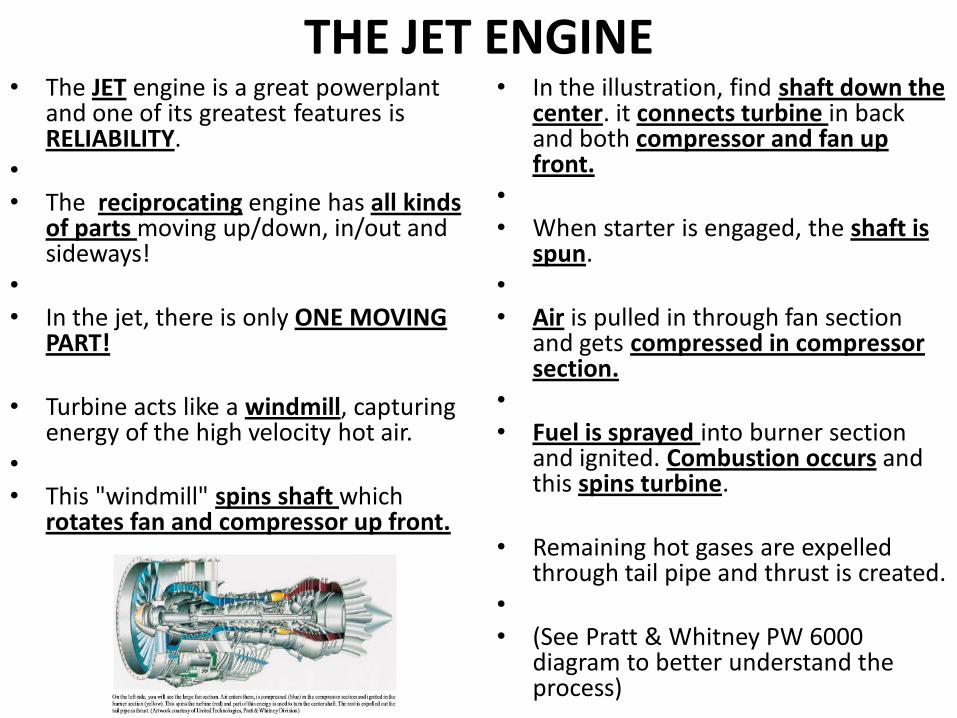
THE JET ENGINE • The JET engine is a great powerplant
and one of its greatest features is RELIABILITY.
• • The reciprocating engine has all kinds
of parts moving up/down, in/out and sideways!
• • In the jet, there is only ONE MOVING
PART!
• Turbine acts like a windmill, capturing energy of the high velocity hot air.
• • This "windmill" spins shaft which
rotates fan and compressor up front.
• In the illustration, find shaft down the center. it connects turbine in back and both compressor and fan up front.
• • When starter is engaged, the shaft is
spun. • • Air is pulled in through fan section
and gets compressed in compressor section.
• • Fuel is sprayed into burner section
and ignited. Combustion occurs and this spins turbine.
• Remaining hot gases are expelled through tail pipe and thrust is created.
• • (See Pratt & Whitney PW 6000
diagram to better understand the process)
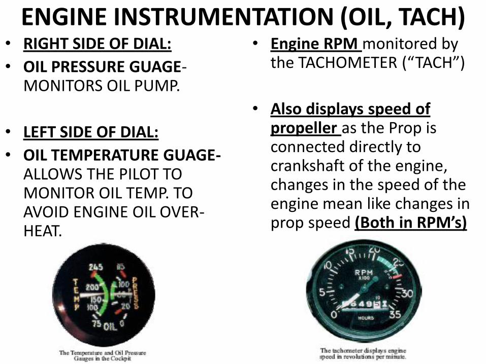
ENGINE INSTRUMENTATION (OIL, TACH) • RIGHT SIDE OF DIAL:
• OIL PRESSURE GUAGE-MONITORS OIL PUMP.
• LEFT SIDE OF DIAL:
• OIL TEMPERATURE GUAGE- ALLOWS THE PILOT TO MONITOR OIL TEMP. TO AVOID ENGINE OIL OVER-HEAT.
• Engine RPM monitored by the TACHOMETER (“TACH”)
• Also displays speed of propeller as the Prop is connected directly to crankshaft of the engine, changes in the speed of the engine mean like changes in prop speed (Both in RPM’s)
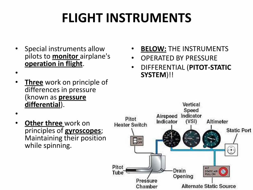
FLIGHT INSTRUMENTS
• Special instruments allow pilots to monitor airplane's operation in flight.
• • Three work on principle of
differences in pressure (known as pressure differential).
• • Other three work on
principles of gyroscopes; Maintaining their position while spinning.
• BELOW: THE INSTRUMENTS • OPERATED BY PRESSURE • DIFFERENTIAL (PITOT-STATIC
SYSTEM)!!
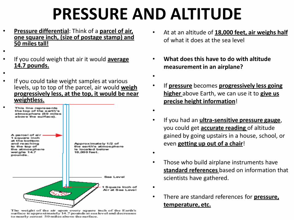
PRESSURE AND ALTITUDE • Pressure differential: Think of a parcel of air,
one square inch, (size of postage stamp) and 50 miles tall!
• • If you could weigh that air it would average
14.7 pounds. • • If you could take weight samples at various
levels, up to top of the parcel, air would weigh progressively less, at the top, it would be near weightless.
•
• At at an altitude of 18,000 feet, air weighs half of what it does at the sea level
• What does this have to do with altitude measurement in an airplane?
•
• If pressure becomes progressively less going higher above Earth, we can use it to give us precise height information!
•
• If you had an ultra-sensitive pressure gauge, you could get accurate reading of altitude gained by going upstairs in a house, school, or even getting up out of a chair!
•
• Those who build airplane instruments have standard references based on information that scientists have gathered.
•
• There are standard references for pressure, temperature, etc.
ATMOSPHERIC PRESSURE STANDARDS AND THE MERCURIAL BAROMETER
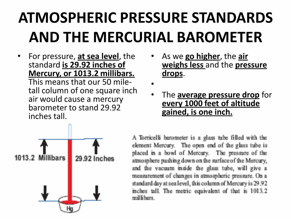
• For pressure, at sea level, the standard is 29.92 inches of Mercury, or 1013.2 millibars. This means that our 50 mile-tall column of one square inch air would cause a mercury barometer to stand 29.92 inches tall.
•
• As we go higher, the air weighs less and the pressure drops.
• • The average pressure drop for
every 1000 feet of altitude gained, is one inch.
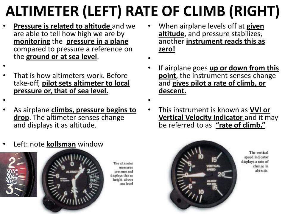
ALTIMETER (LEFT) RATE OF CLIMB (RIGHT) • Pressure is related to altitude and we
are able to tell how high we are by monitoring the pressure in a plane compared to pressure a reference on the ground or at sea level.
• • That is how altimeters work. Before
take-off, pilot sets altimeter to local pressure or, that of sea level.
• • As airplane climbs, pressure begins to
drop. The altimeter senses change and displays it as altitude.
• Left: note kollsman window
• When airplane levels off at given altitude, and pressure stabilizes, another instrument reads this as zero!
• • If airplane goes up or down from this
point, the instrument senses change and gives pilot a rate of climb, or descent.
• • This instrument is known as VVI or
Vertical Velocity Indicator and it may be referred to as “rate of climb.”
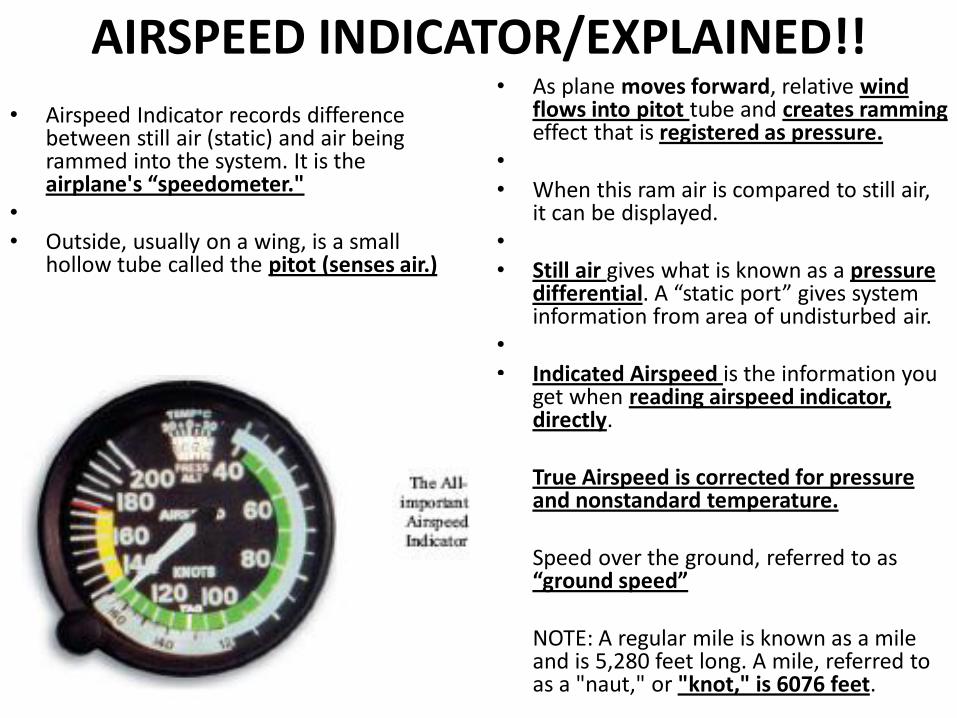
AIRSPEED INDICATOR/EXPLAINED!!
• Airspeed Indicator records difference between still air (static) and air being rammed into the system. It is the airplane's “speedometer."
• • Outside, usually on a wing, is a small
hollow tube called the pitot (senses air.)
• As plane moves forward, relative wind flows into pitot tube and creates ramming effect that is registered as pressure.
• • When this ram air is compared to still air,
it can be displayed. • • Still air gives what is known as a pressure
differential. A “static port” gives system information from area of undisturbed air.
• • Indicated Airspeed is the information you
get when reading airspeed indicator, directly.
• True Airspeed is corrected for pressure and nonstandard temperature.
• Speed over the ground, referred to as “ground speed”
• NOTE: A regular mile is known as a mile and is 5,280 feet long. A mile, referred to as a "naut," or "knot," is 6076 feet.
GYROSCOPIC INSTRUMENTATION
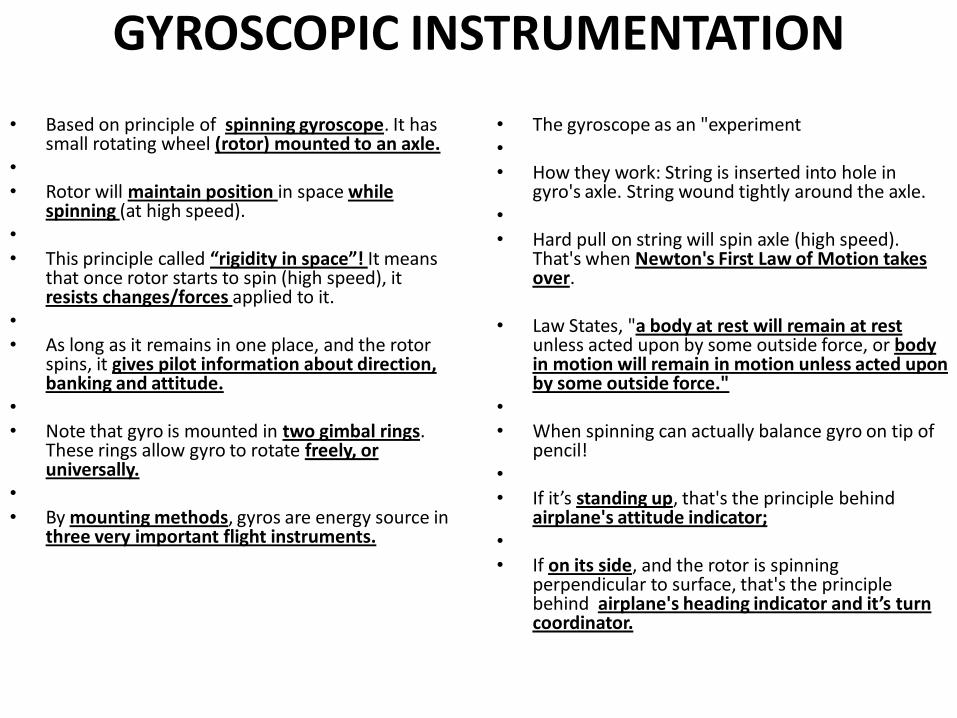
• Based on principle of spinning gyroscope. It has small rotating wheel (rotor) mounted to an axle.
• • Rotor will maintain position in space while
spinning (at high speed). • • This principle called “rigidity in space”! It means
that once rotor starts to spin (high speed), it resists changes/forces applied to it.
• • As long as it remains in one place, and the rotor
spins, it gives pilot information about direction, banking and attitude.
• • Note that gyro is mounted in two gimbal rings.
These rings allow gyro to rotate freely, or universally.
• • By mounting methods, gyros are energy source in
three very important flight instruments.
• The gyroscope as an "experiment • • How they work: String is inserted into hole in
gyro's axle. String wound tightly around the axle. • • Hard pull on string will spin axle (high speed).
That's when Newton's First Law of Motion takes over.
• Law States, "a body at rest will remain at rest unless acted upon by some outside force, or body in motion will remain in motion unless acted upon by some outside force."
• • When spinning can actually balance gyro on tip of
pencil! • • If it’s standing up, that's the principle behind
airplane's attitude indicator; • • If on its side, and the rotor is spinning
perpendicular to surface, that's the principle behind airplane's heading indicator and it’s turn coordinator.
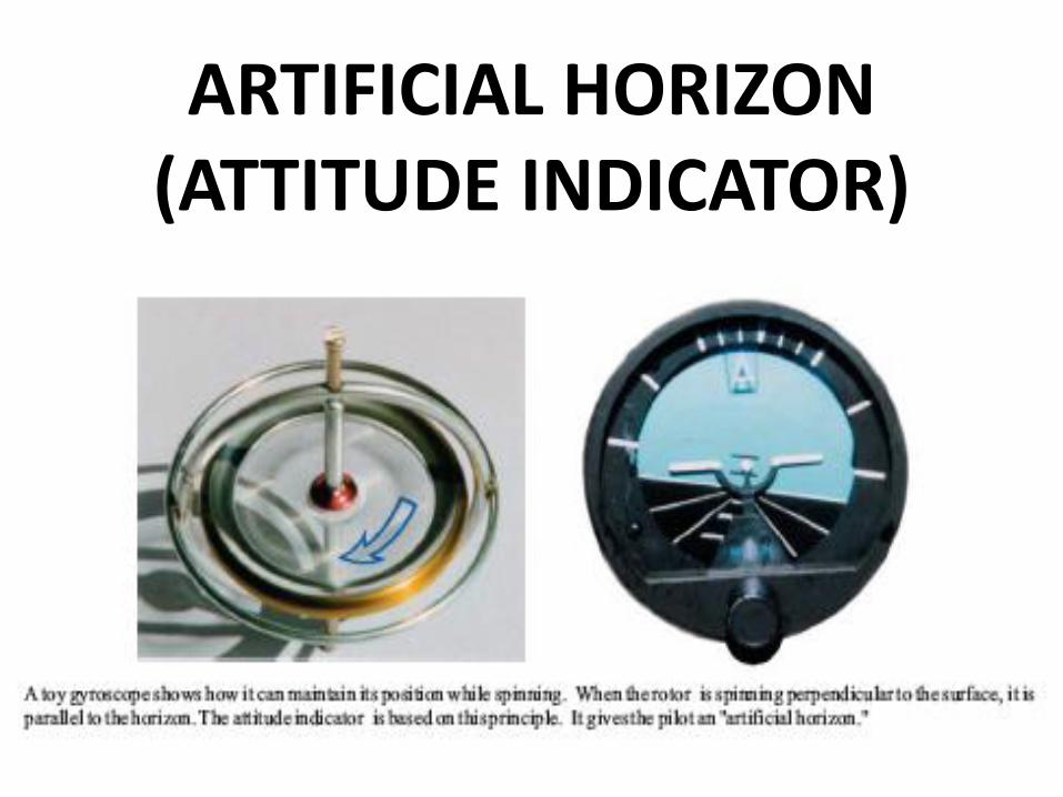
ARTIFICIAL HORIZON (ATTITUDE INDICATOR)
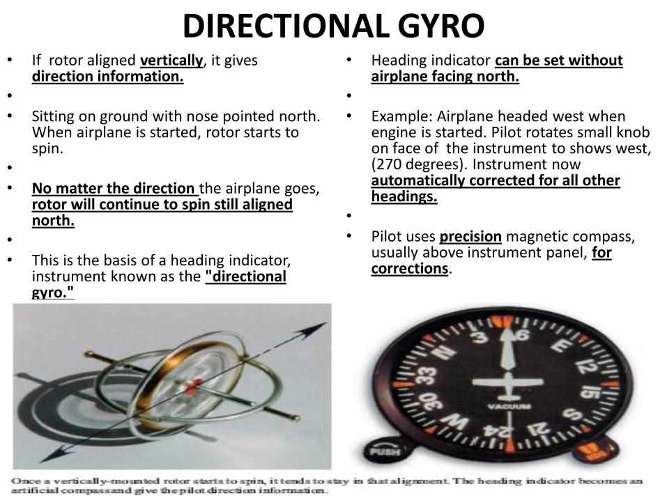
DIRECTIONAL GYRO • If rotor aligned vertically, it gives
direction information. • • Sitting on ground with nose pointed north.
When airplane is started, rotor starts to spin.
• • No matter the direction the airplane goes,
rotor will continue to spin still aligned north.
• • This is the basis of a heading indicator,
instrument known as the "directional gyro."
• Heading indicator can be set without airplane facing north.
• • Example: Airplane headed west when
engine is started. Pilot rotates small knob on face of the instrument to shows west, (270 degrees). Instrument now automatically corrected for all other headings.
• • Pilot uses precision magnetic compass,
usually above instrument panel, for corrections.
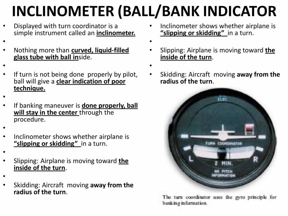
INCLINOMETER (BALL/BANK INDICATOR • Displayed with turn coordinator is a
simple instrument called an inclinometer. • • Nothing more than curved, liquid-filled
glass tube with ball inside. • • If turn is not being done properly by pilot,
ball will give a clear indication of poor technique.
• • If banking maneuver is done properly, ball
will stay in the center through the procedure.
• • Inclinometer shows whether airplane is
“slipping or skidding” in a turn. • • Slipping: Airplane is moving toward the
inside of the turn. • • Skidding: Aircraft moving away from the
radius of the turn.
• Inclinometer shows whether airplane is “slipping or skidding” in a turn.
• • Slipping: Airplane is moving toward the
inside of the turn. • • Skidding: Aircraft moving away from the
radius of the turn.
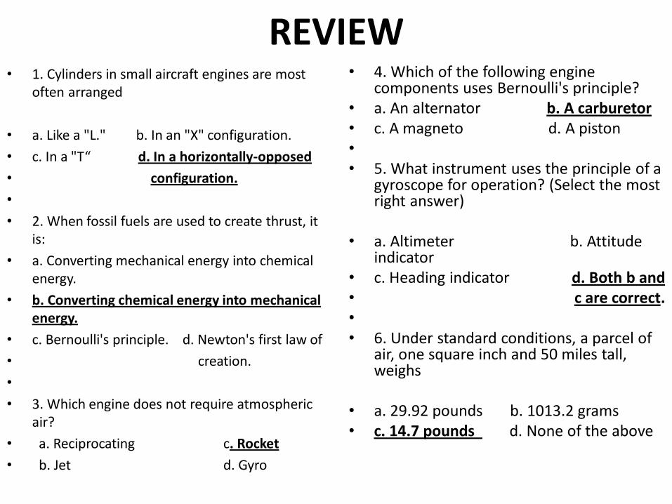
REVIEW • 1. Cylinders in small aircraft engines are most
often arranged
• a. Like a "L." b. In an "X" configuration.
• c. In a "T“ d. In a horizontally-opposed
• configuration.
•
• 2. When fossil fuels are used to create thrust, it is:
• a. Converting mechanical energy into chemical energy.
• b. Converting chemical energy into mechanical energy.
• c. Bernoulli's principle. d. Newton's first law of
• creation.
•
• 3. Which engine does not require atmospheric air?
• a. Reciprocating c. Rocket
• b. Jet d. Gyro
• 4. Which of the following engine components uses Bernoulli's principle?
• a. An alternator b. A carburetor • c. A magneto d. A piston • • 5. What instrument uses the principle of a
gyroscope for operation? (Select the most right answer)
• a. Altimeter b. Attitude indicator
• c. Heading indicator d. Both b and • c are correct. • • 6. Under standard conditions, a parcel of
air, one square inch and 50 miles tall, weighs
• a. 29.92 pounds b. 1013.2 grams • c. 14.7 pounds d. None of the above
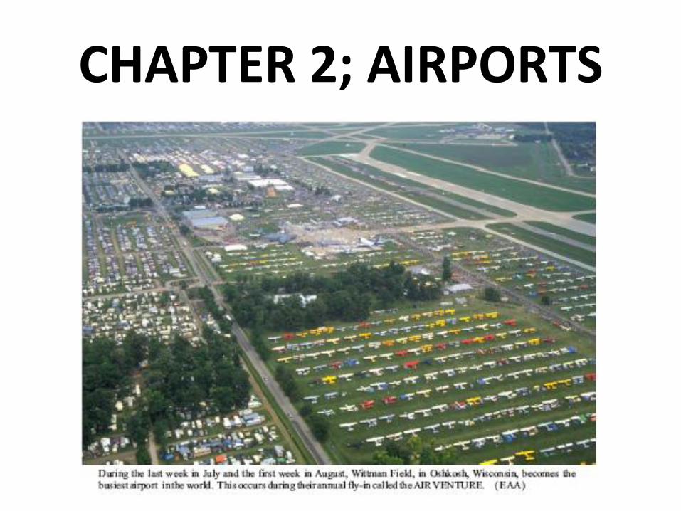
CHAPTER 2; AIRPORTS
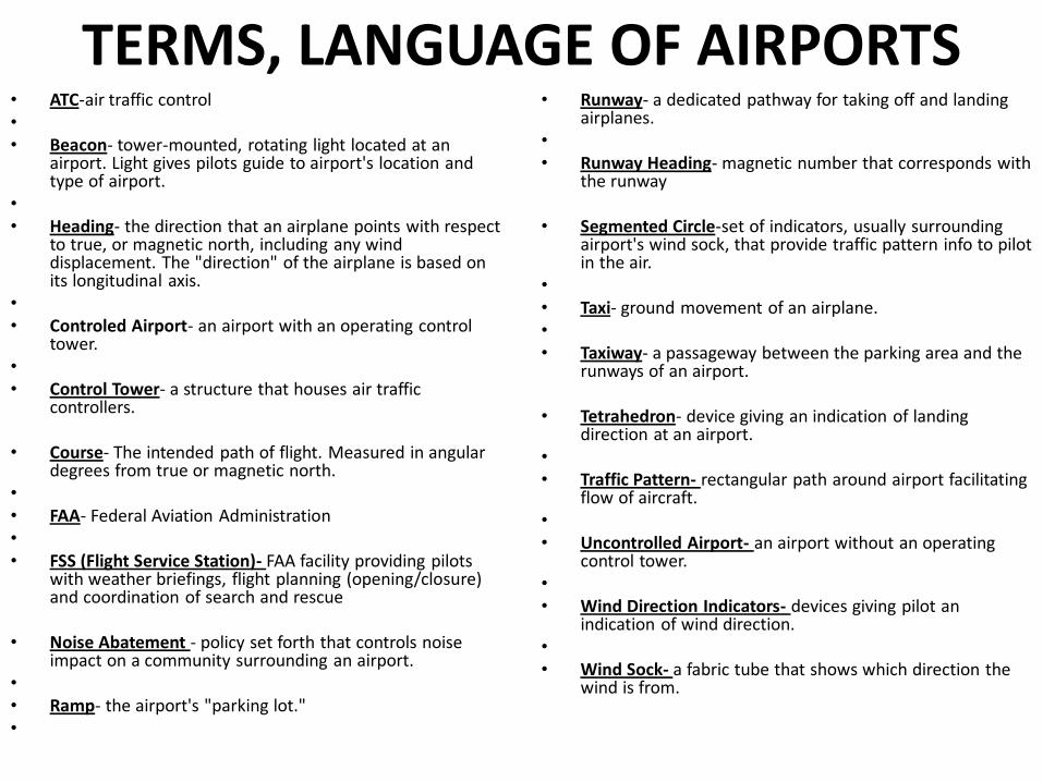
TERMS, LANGUAGE OF AIRPORTS • ATC-air traffic control • • Beacon- tower-mounted, rotating light located at an
airport. Light gives pilots guide to airport's location and type of airport.
• • Heading- the direction that an airplane points with respect
to true, or magnetic north, including any wind displacement. The "direction" of the airplane is based on its longitudinal axis.
• • Controled Airport- an airport with an operating control
tower. • • Control Tower- a structure that houses air traffic
controllers.
• Course- The intended path of flight. Measured in angular degrees from true or magnetic north.
• • FAA- Federal Aviation Administration • • FSS (Flight Service Station)- FAA facility providing pilots
with weather briefings, flight planning (opening/closure) and coordination of search and rescue
• Noise Abatement - policy set forth that controls noise impact on a community surrounding an airport.
• • Ramp- the airport's "parking lot." •
• Runway- a dedicated pathway for taking off and landing airplanes.
• • Runway Heading- magnetic number that corresponds with
the runway
• Segmented Circle-set of indicators, usually surrounding airport's wind sock, that provide traffic pattern info to pilot in the air.
• • Taxi- ground movement of an airplane. • • Taxiway- a passageway between the parking area and the
runways of an airport.
• Tetrahedron- device giving an indication of landing direction at an airport.
• • Traffic Pattern- rectangular path around airport facilitating
flow of aircraft. • • Uncontrolled Airport- an airport without an operating
control tower. • • Wind Direction Indicators- devices giving pilot an
indication of wind direction. • • Wind Sock- a fabric tube that shows which direction the
wind is from.
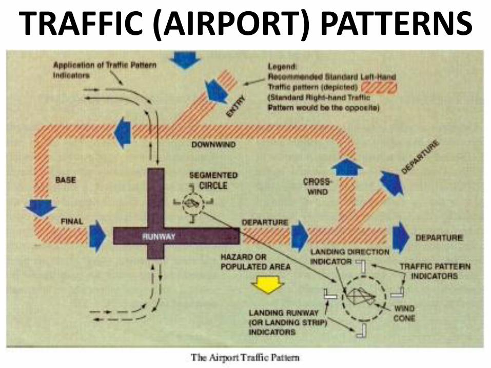
TRAFFIC (AIRPORT) PATTERNS
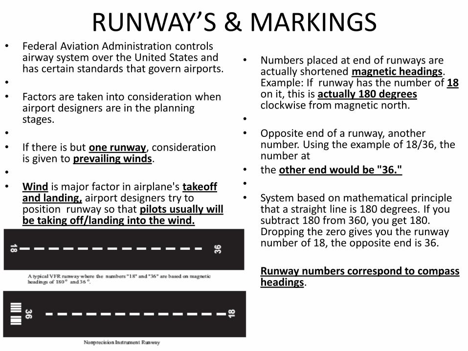
RUNWAY’S & MARKINGS • Federal Aviation Administration controls
airway system over the United States and has certain standards that govern airports.
• • Factors are taken into consideration when
airport designers are in the planning stages.
• • If there is but one runway, consideration
is given to prevailing winds. • • Wind is major factor in airplane's takeoff
and landing, airport designers try to position runway so that pilots usually will be taking off/landing into the wind.
• Numbers placed at end of runways are
actually shortened magnetic headings. Example: If runway has the number of 18 on it, this is actually 180 degrees clockwise from magnetic north.
• • Opposite end of a runway, another
number. Using the example of 18/36, the number at
• the other end would be "36." • • System based on mathematical principle
that a straight line is 180 degrees. If you subtract 180 from 360, you get 180. Dropping the zero gives you the runway number of 18, the opposite end is 36.
• • Runway numbers correspond to compass
headings.
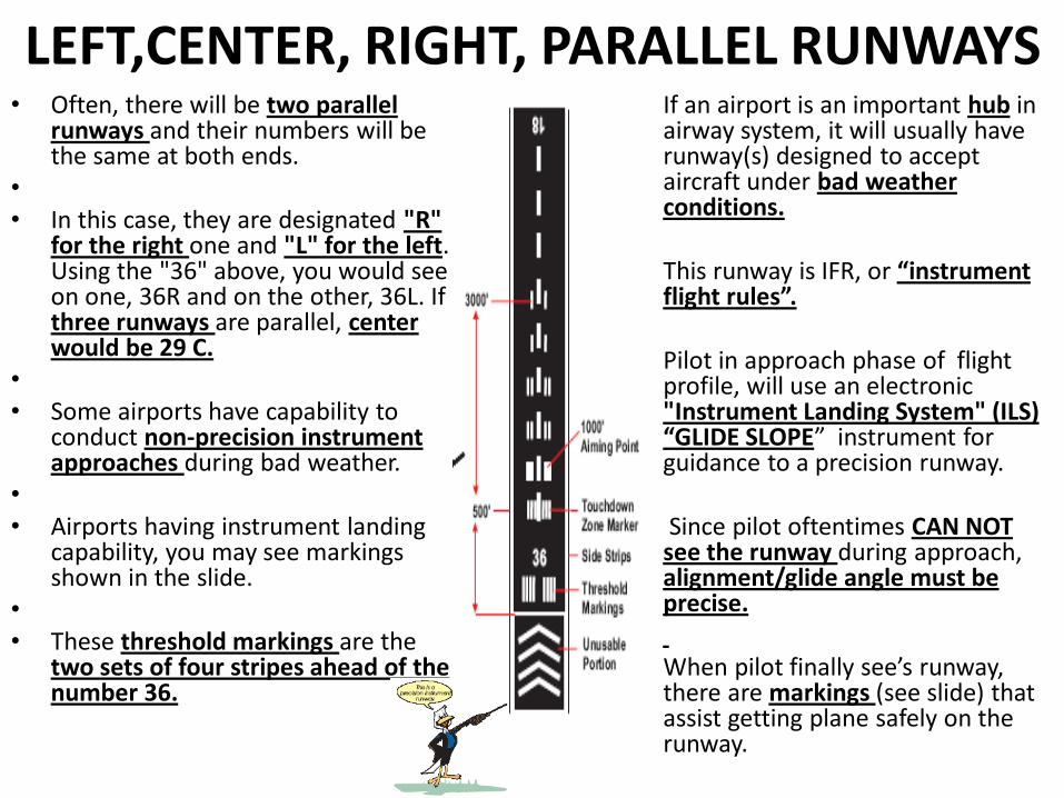
LEFT,CENTER, RIGHT, PARALLEL RUNWAYS • Often, there will be two parallel
runways and their numbers will be the same at both ends.
• • In this case, they are designated "R"
for the right one and "L" for the left. Using the "36" above, you would see on one, 36R and on the other, 36L. If three runways are parallel, center would be 29 C.
• • Some airports have capability to
conduct non-precision instrument approaches during bad weather.
• • Airports having instrument landing
capability, you may see markings shown in the slide.
• • These threshold markings are the
two sets of four stripes ahead of the number 36.
• If an airport is an important hub in airway system, it will usually have runway(s) designed to accept aircraft under bad weather conditions.
• • This runway is IFR, or “instrument
flight rules”. • • Pilot in approach phase of flight
profile, will use an electronic "Instrument Landing System" (ILS) “GLIDE SLOPE” instrument for guidance to a precision runway.
• • Since pilot oftentimes CAN NOT
see the runway during approach, alignment/glide angle must be precise.
• • When pilot finally see’s runway,
there are markings (see slide) that assist getting plane safely on the runway.
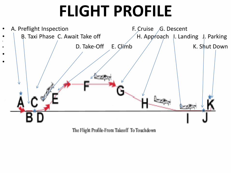
FLIGHT PROFILE • A. Preflight Inspection F. Cruise G. Descent • B. Taxi Phase C. Await Take off H. Approach I. Landing J. Parking •
• D. Take-Off E. Climb K. Shut Down • •
• F. Cruise G . Descent H . Landing Approach I. Landing J. Taxi Clearance/ Stop •
• K. Shut-Down
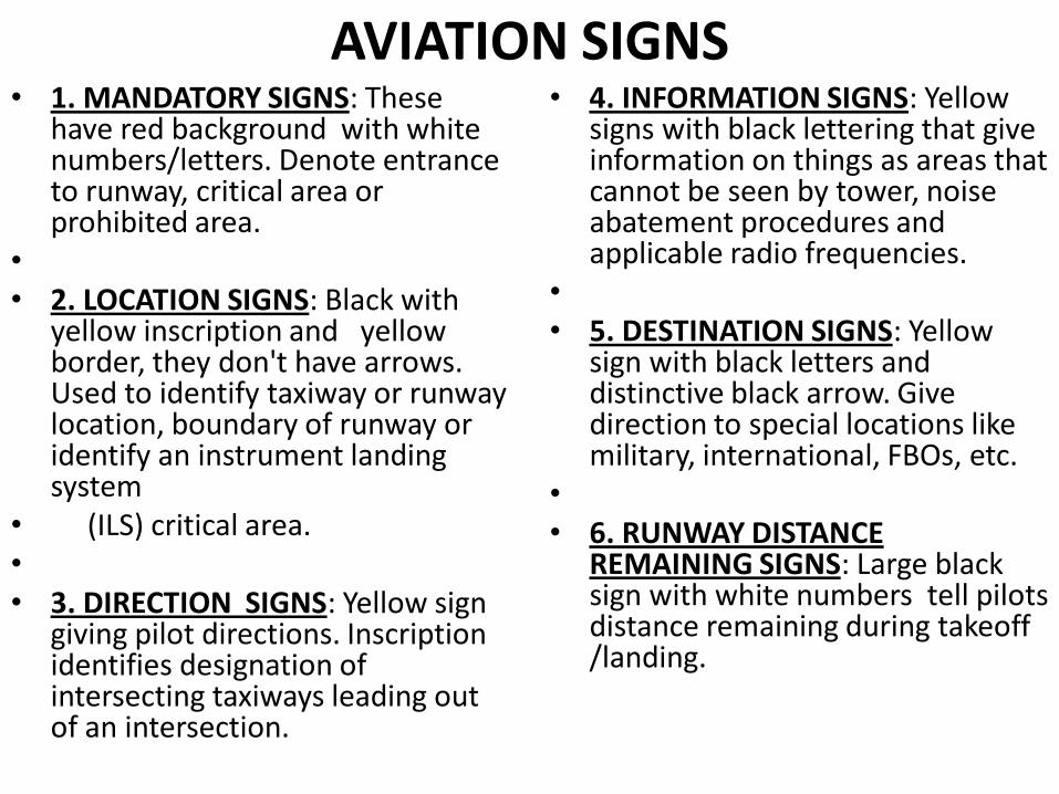
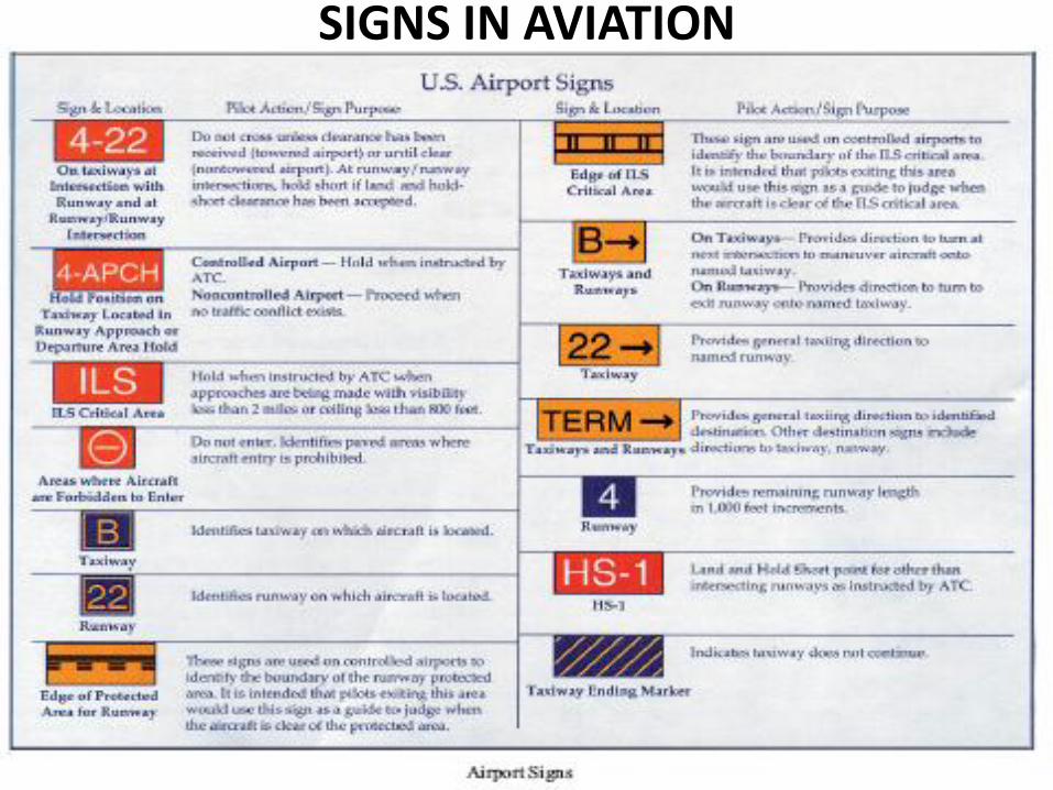
AVIATION SIGNS • 1. MANDATORY SIGNS: These
have red background with white numbers/letters. Denote entrance to runway, critical area or prohibited area.
• • 2. LOCATION SIGNS: Black with
yellow inscription and yellow border, they don't have arrows. Used to identify taxiway or runway location, boundary of runway or identify an instrument landing system
• (ILS) critical area. • • 3. DIRECTION SIGNS: Yellow sign
giving pilot directions. Inscription identifies designation of intersecting taxiways leading out of an intersection.
• 4. INFORMATION SIGNS: Yellow signs with black lettering that give information on things as areas that cannot be seen by tower, noise abatement procedures and applicable radio frequencies.
• • 5. DESTINATION SIGNS: Yellow
sign with black letters and distinctive black arrow. Give direction to special locations like military, international, FBOs, etc.
• • 6. RUNWAY DISTANCE
REMAINING SIGNS: Large black sign with white numbers tell pilots distance remaining during takeoff /landing.
SIGNS IN AVIATION
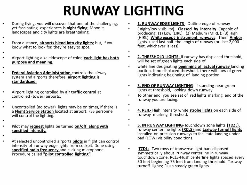
RUNWAY LIGHTING • During flying, you will discover that one of the challenging,
yet fascinating experiences is night flying. Moonlit landscapes and city lights are breathtaking.
• • From distance, airports blend into city lights; but, if you
know what to look for, they’re easy to spot. • • Airport lighting a kaleidoscope of color, each light has both
purpose and meaning. • • Federal Aviation Administration controls the airway
system and airports therefore, airport lighting is standardized.
• Airport lighting controlled by air traffic control at controlled (tower) airports.
• • Uncontrolled (no tower) lights may be on timer, if there is
a Flight Service Station located at airport, FSS personnel will control the lighting.
• • Pilot may request lights be turned on/off along with
specified intensity. • • At selected uncontrolled airports pilots in flight can control
intensity of runway edge lights from cockpit. Done using specified radio frequency and clicking microphone. Procedure called "pilot controlled lighting”.
• 1. RUNWAY EDGE LIGHTS - Outline edge of runway • ( night/low visibility). Classed by intensity. Capable of
producing: (1) Low (LIRL); (2) Medium (MIRL ); (3) High (HIRL). White except instrument runways. Then Amber lights used last half the length of runway (or last 2,000 feet, whichever is less).
• • 2. THRESHOLD LIGHTS- If runway has displaced threshold,
will be set of green lights each side of • white line designating beginning of actual runway landing
portion. If no displaced threshold, there will row of green lights indicating beginning of landing portion.
• 3. END OF RUNWAY LIGHTING- If standing near green lights at threshold, looking down runway
• To other end, you see set of red lights marking end of the runway you are facing.
• • 4. REIL- High intensity white strobe lights on each side of
runway marking threshold. • • 5. IN RUNWAY LIGHTING-Touchdown zone lights (TDZL),
runway centerline lights (RCLS) and taxiway turnoff lights installed on precision runways to facilitate landing under bad (LOW) visibility conditions.
• TZDLs- Two rows of transverse light bars disposed symmetrically about runway centerline in runway touchdown zone. RCLS-Flush centerline lights spaced every 50 feet beginning 75 feet from landing threshold. Taxiway turnoff lights; Flush steady green lights.
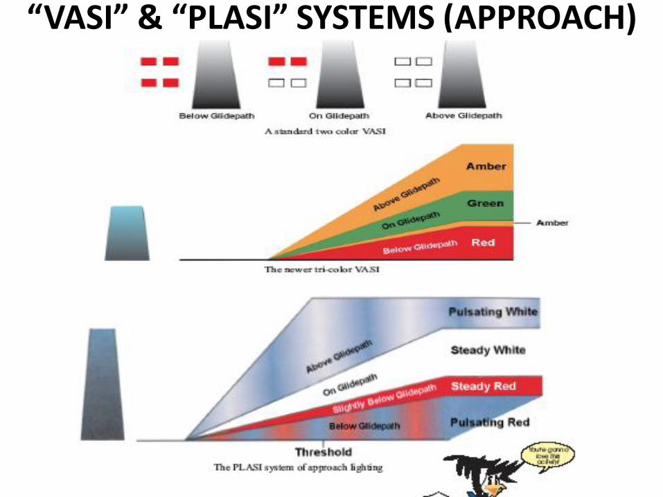
“VASI” & “PLASI” SYSTEMS (APPROACH)
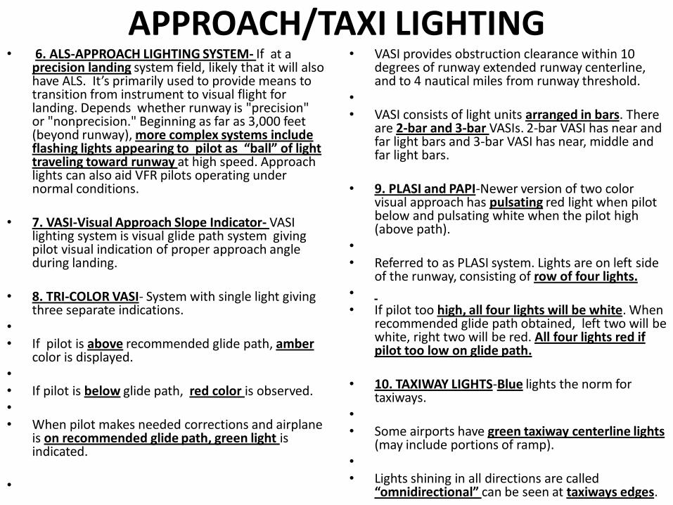
APPROACH/TAXI LIGHTING • 6. ALS-APPROACH LIGHTING SYSTEM- If at a
precision landing system field, likely that it will also have ALS. It’s primarily used to provide means to transition from instrument to visual flight for landing. Depends whether runway is "precision" or "nonprecision." Beginning as far as 3,000 feet (beyond runway), more complex systems include flashing lights appearing to pilot as “ball” of light traveling toward runway at high speed. Approach lights can also aid VFR pilots operating under normal conditions.
• 7. VASI-Visual Approach Slope Indicator- VASI lighting system is visual glide path system giving pilot visual indication of proper approach angle during landing.
• 8. TRI-COLOR VASI- System with single light giving three separate indications.
• • If pilot is above recommended glide path, amber
color is displayed. • • If pilot is below glide path, red color is observed. • • When pilot makes needed corrections and airplane
is on recommended glide path, green light is indicated.
•
• VASI provides obstruction clearance within 10 degrees of runway extended runway centerline, and to 4 nautical miles from runway threshold.
• • VASI consists of light units arranged in bars. There
are 2-bar and 3-bar VASIs. 2-bar VASI has near and far light bars and 3-bar VASI has near, middle and far light bars.
• 9. PLASI and PAPI-Newer version of two color visual approach has pulsating red light when pilot below and pulsating white when the pilot high (above path).
• • Referred to as PLASI system. Lights are on left side
of the runway, consisting of row of four lights. • • If pilot too high, all four lights will be white. When
recommended glide path obtained, left two will be white, right two will be red. All four lights red if pilot too low on glide path.
• 10. TAXIWAY LIGHTS-Blue lights the norm for taxiways.
• • Some airports have green taxiway centerline lights
(may include portions of ramp). • • Lights shining in all directions are called
“omnidirectional” can be seen at taxiways edges.
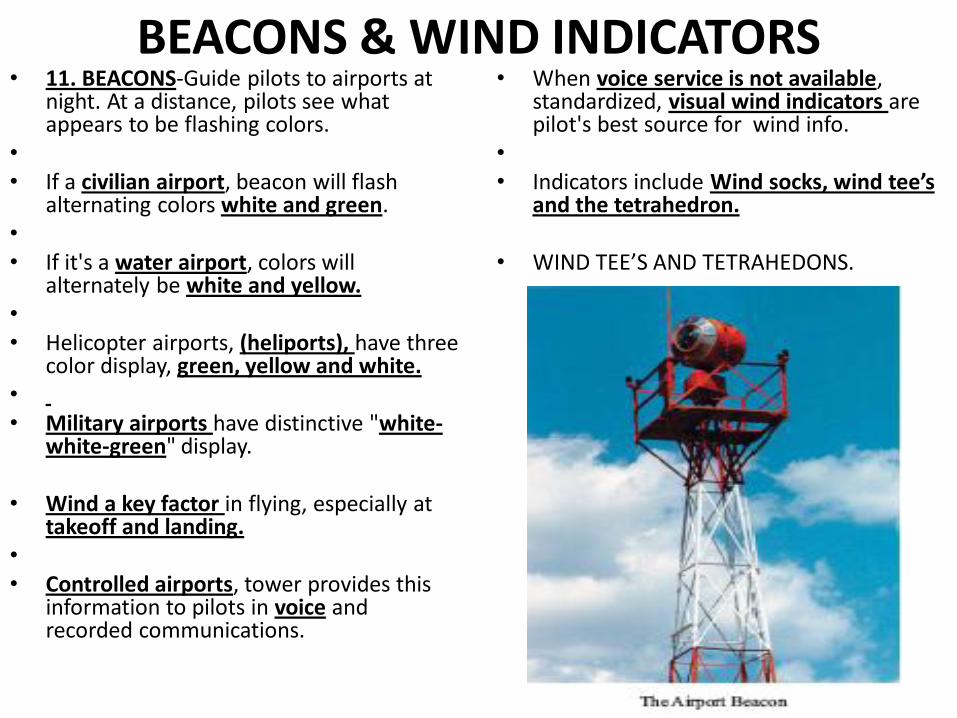
BEACONS & WIND INDICATORS • 11. BEACONS-Guide pilots to airports at
night. At a distance, pilots see what appears to be flashing colors.
• • If a civilian airport, beacon will flash
alternating colors white and green. • • If it's a water airport, colors will
alternately be white and yellow. • • Helicopter airports, (heliports), have three
color display, green, yellow and white. • • Military airports have distinctive "white-
white-green" display.
• Wind a key factor in flying, especially at takeoff and landing.
• • Controlled airports, tower provides this
information to pilots in voice and recorded communications.
• When voice service is not available, standardized, visual wind indicators are pilot's best source for wind info.
• • Indicators include Wind socks, wind tee’s
and the tetrahedron.
• WIND TEE’S AND TETRAHEDONS.
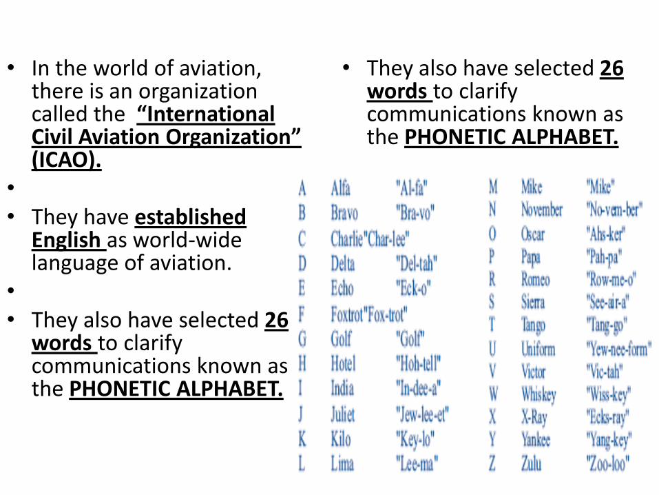
• In the world of aviation, there is an organization called the “International Civil Aviation Organization” (ICAO).
• • They have established
English as world-wide language of aviation.
• • They also have selected 26
words to clarify communications known as the PHONETIC ALPHABET.
• They also have selected 26 words to clarify communications known as the PHONETIC ALPHABET.
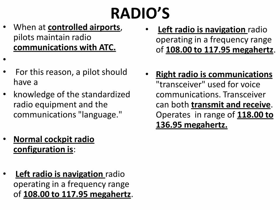
RADIO’S • When at controlled airports,
pilots maintain radio communications with ATC.
•
• For this reason, a pilot should have a
• knowledge of the standardized radio equipment and the communications "language."
• Normal cockpit radio configuration is:
• Left radio is navigation radio operating in a frequency range of 108.00 to 117.95 megahertz.
• Left radio is navigation radio operating in a frequency range of 108.00 to 117.95 megahertz.
• Right radio is communications "transceiver" used for voice communications. Transceiver can both transmit and receive. Operates in range of 118.00 to 136.95 megahertz.
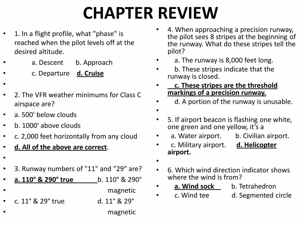
CHAPTER REVIEW • 1. In a flight profile, what "phase" is
reached when the pilot levels off at the desired altitude.
• a. Descent b. Approach
• c. Departure d. Cruise
•
• 2. The VFR weather minimums for Class C airspace are?
• a. 500' below clouds
• b. 1000' above clouds
• c. 2,000 feet horizontally from any cloud
• d. All of the above are correct.
•
• 3. Runway numbers of "11" and "29" are?
• a. 110° & 290° true b. 110° & 290°
• magnetic
• c. 11° & 29° true d. 11° & 29°
• magnetic
• 4. When approaching a precision runway, the pilot sees 8 stripes at the beginning of the runway. What do these stripes tell the pilot?
• a. The runway is 8,000 feet long. • b. These stripes indicate that the
runway is closed. • c. These stripes are the threshold
markings of a precision runway. • d. A portion of the runway is unusable. • • 5. If airport beacon is flashing one white,
one green and one yellow, it’s a • a. Water airport. b. Civilian airport. • c. Military airport. d. Helicopter
airport. • • 6. Which wind direction indicator shows
where the wind is from? • a. Wind sock b. Tetrahedron • c. Wind tee d. Segmented circle
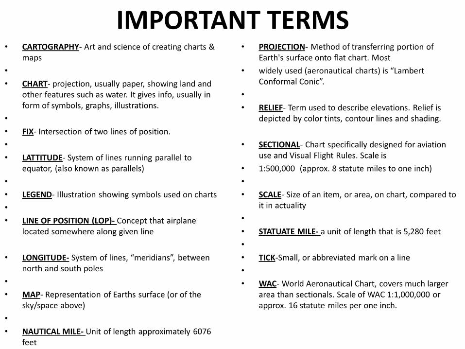
IMPORTANT TERMS • CARTOGRAPHY- Art and science of creating charts &
maps
•
• CHART- projection, usually paper, showing land and other features such as water. It gives info, usually in form of symbols, graphs, illustrations.
•
• FIX- Intersection of two lines of position.
•
• LATTITUDE- System of lines running parallel to equator, (also known as parallels)
•
• LEGEND- Illustration showing symbols used on charts
•
• LINE OF POSITION (LOP)- Concept that airplane located somewhere along given line
• LONGITUDE- System of lines, “meridians”, between north and south poles
•
• MAP- Representation of Earths surface (or of the sky/space above)
•
• NAUTICAL MILE- Unit of length approximately 6076 feet
• PROJECTION- Method of transferring portion of Earth's surface onto flat chart. Most
• widely used (aeronautical charts) is “Lambert Conformal Conic”.
•
• RELIEF- Term used to describe elevations. Relief is depicted by color tints, contour lines and shading.
• SECTIONAL- Chart specifically designed for aviation use and Visual Flight Rules. Scale is
• 1:500,000 (approx. 8 statute miles to one inch)
•
• SCALE- Size of an item, or area, on chart, compared to it in actuality
•
• STATUATE MILE- a unit of length that is 5,280 feet
•
• TICK-Small, or abbreviated mark on a line
•
• WAC- World Aeronautical Chart, covers much larger area than sectionals. Scale of WAC 1:1,000,000 or approx. 16 statute miles per one inch.
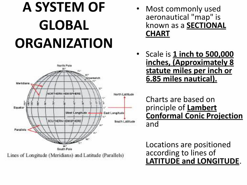
A SYSTEM OF GLOBAL
ORGANIZATION
• Most commonly used aeronautical "map" is known as a SECTIONAL CHART
• Scale is 1 inch to 500,000 inches, (Approximately 8 statute miles per inch or 6.85 miles nautical).
• • Charts are based on
principle of Lambert Conformal Conic Projection and
• Locations are positioned according to lines of LATITUDE and LONGITUDE.
PROBLEM: • FOR THE REMAINDER OF THIS SECTION
DEALING WITH CHARTS, I APPOLOGIZE!! • I COULD FIND NO WAY AND NO CHARTS
AVAILABLE THAT ALLOWED ME TO MAINTAIN CLARITY AND RESOLUTION, ESPECIALLY WITH THOSE REMAINING, BUT TO SOME EXTENT, WITH ALL THE CHARTS IN THIS SECTION (CHAP. THREE).
• Jerry Painter (CAPT., CAP)
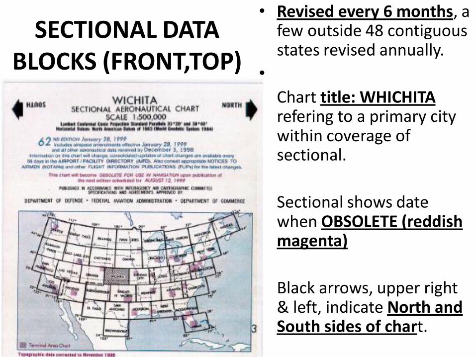
SECTIONAL DATA BLOCKS (FRONT,TOP)
• Revised every 6 months, a few outside 48 contiguous states revised annually.
•
• Chart title: WHICHITA refering to a primary city within coverage of sectional.
•
• Sectional shows date when OBSOLETE (reddish magenta)
•
• Black arrows, upper right & left, indicate North and South sides of chart.
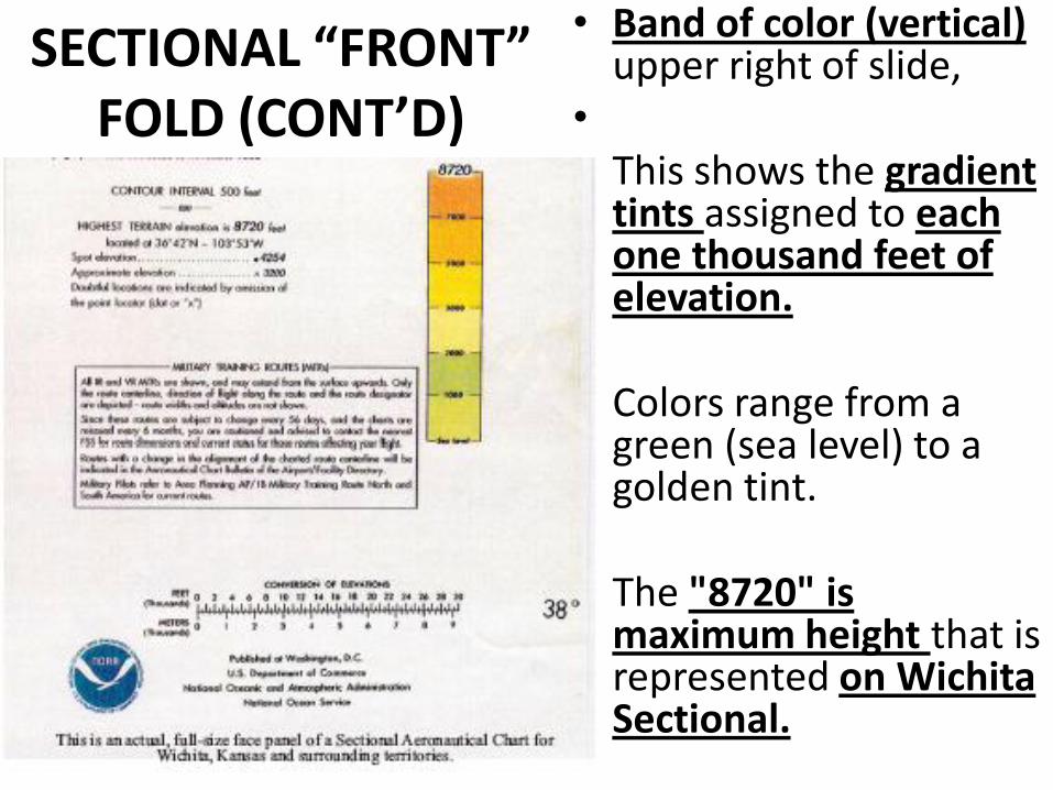
SECTIONAL “FRONT” FOLD (CONT’D)
• Band of color (vertical) upper right of slide,
• • This shows the gradient
tints assigned to each one thousand feet of elevation.
• • Colors range from a
green (sea level) to a golden tint.
• • The "8720" is
maximum height that is represented on Wichita Sectional.
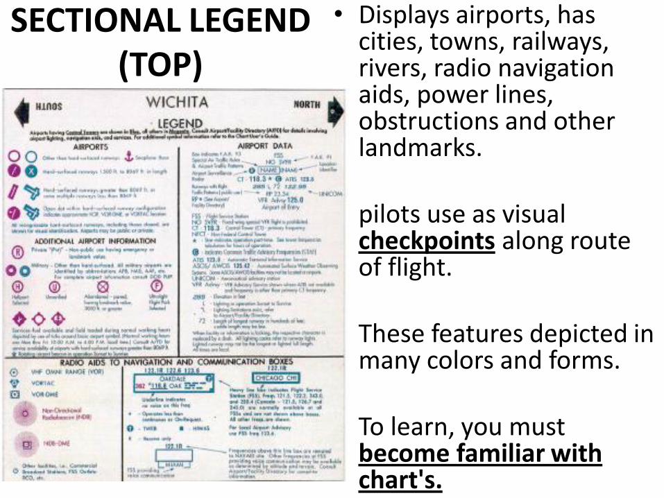
SECTIONAL LEGEND (TOP)
• Displays airports, has cities, towns, railways, rivers, radio navigation aids, power lines, obstructions and other landmarks.
• • pilots use as visual
checkpoints along route of flight.
• • These features depicted in
many colors and forms. • • To learn, you must
become familiar with chart's.
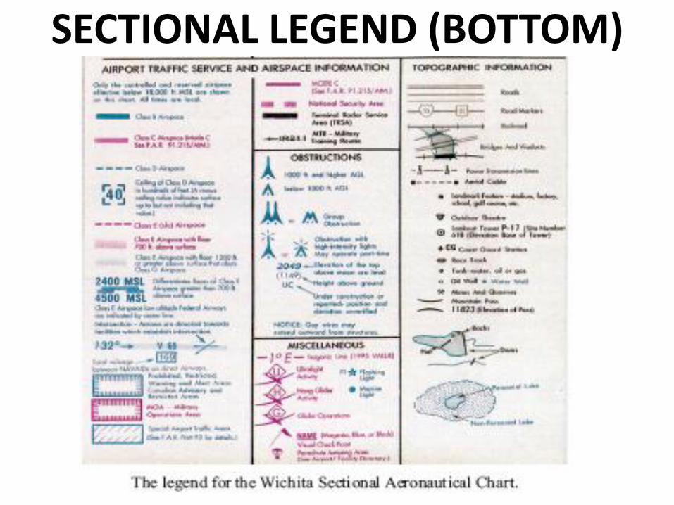
SECTIONAL LEGEND (BOTTOM)
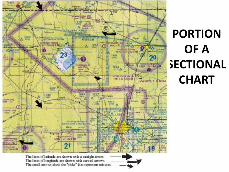
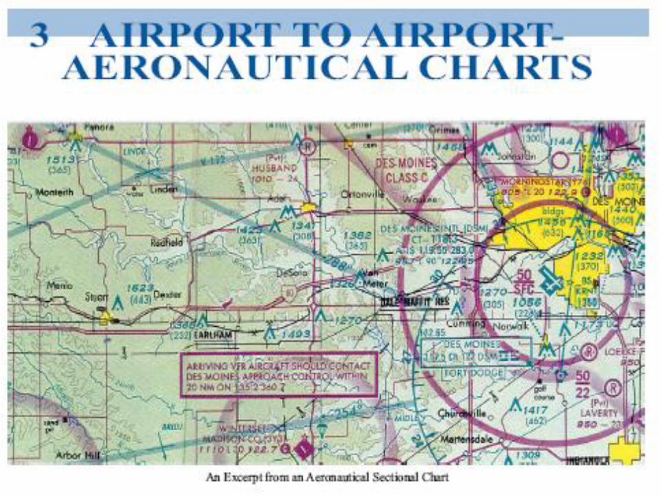
PORTION OF A
SECTIONAL CHART
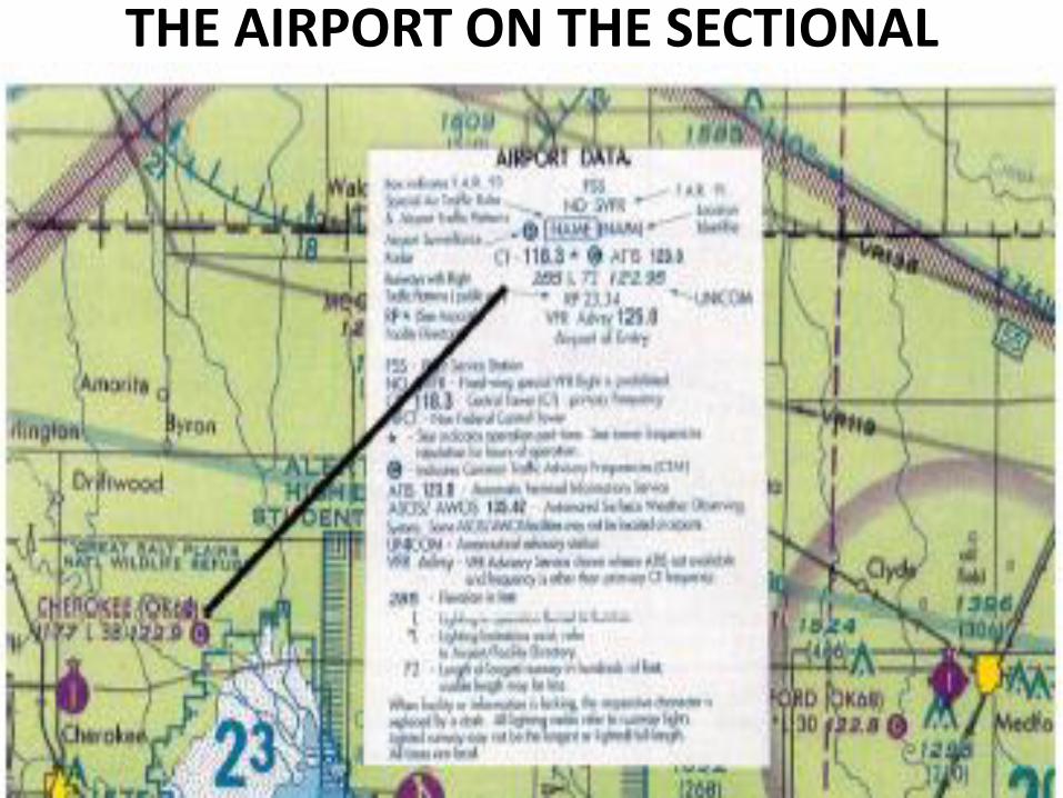
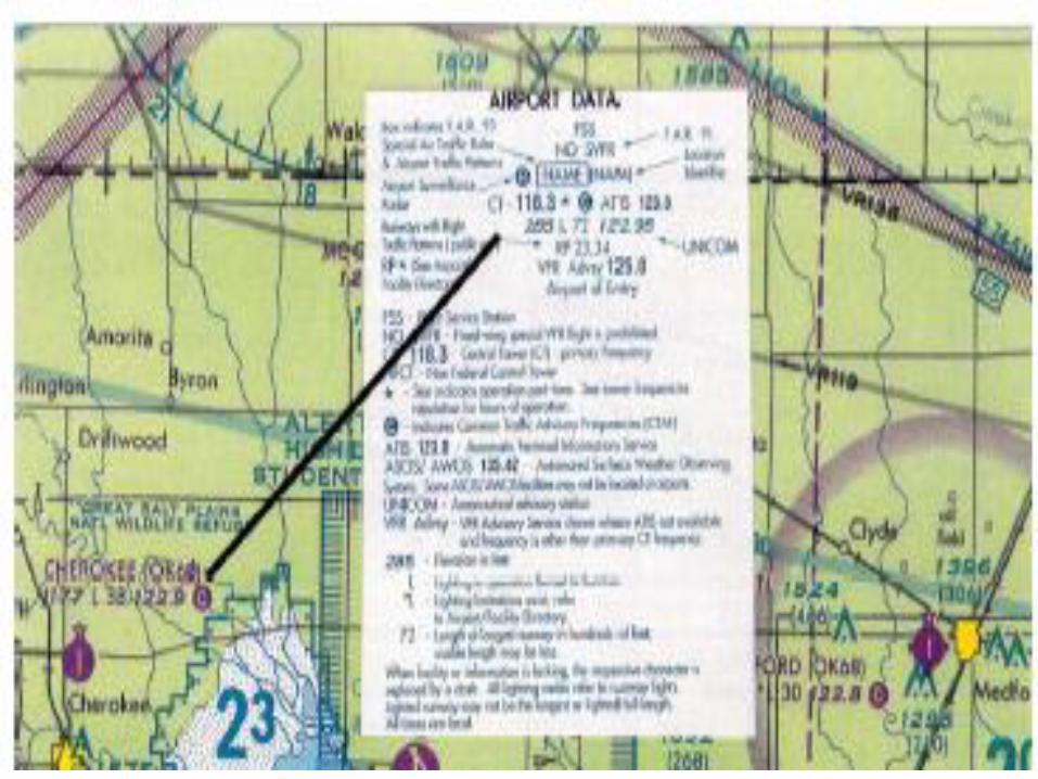
THE AIRPORT ON THE SECTIONAL
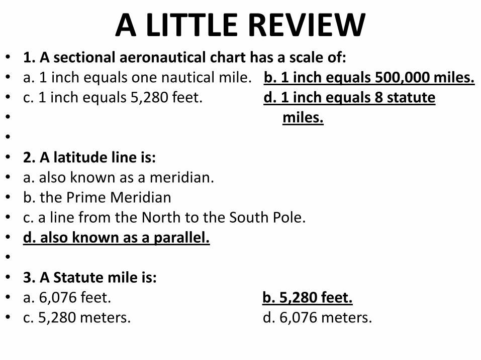
A LITTLE REVIEW • 1. A sectional aeronautical chart has a scale of: • a. 1 inch equals one nautical mile. b. 1 inch equals 500,000 miles. • c. 1 inch equals 5,280 feet. d. 1 inch equals 8 statute • miles. • • 2. A latitude line is: • a. also known as a meridian. • b. the Prime Meridian • c. a line from the North to the South Pole. • d. also known as a parallel. • • 3. A Statute mile is: • a. 6,076 feet. b. 5,280 feet. • c. 5,280 meters. d. 6,076 meters.
CIVIL AIR PATROL SQUADRON 316, CASA GRANDE
(ARIZONA WING)
• THIS CONCLUDES OUR REVIEW BASED
• ON MODULE 2, “AIRCRAFT SYSTEMS
• AND AIRPORTS”.
• THANK YOU FOR YOUR ATTENTION!
• CAPTAIN PAINTER