Embed Size (px)
Citation preview
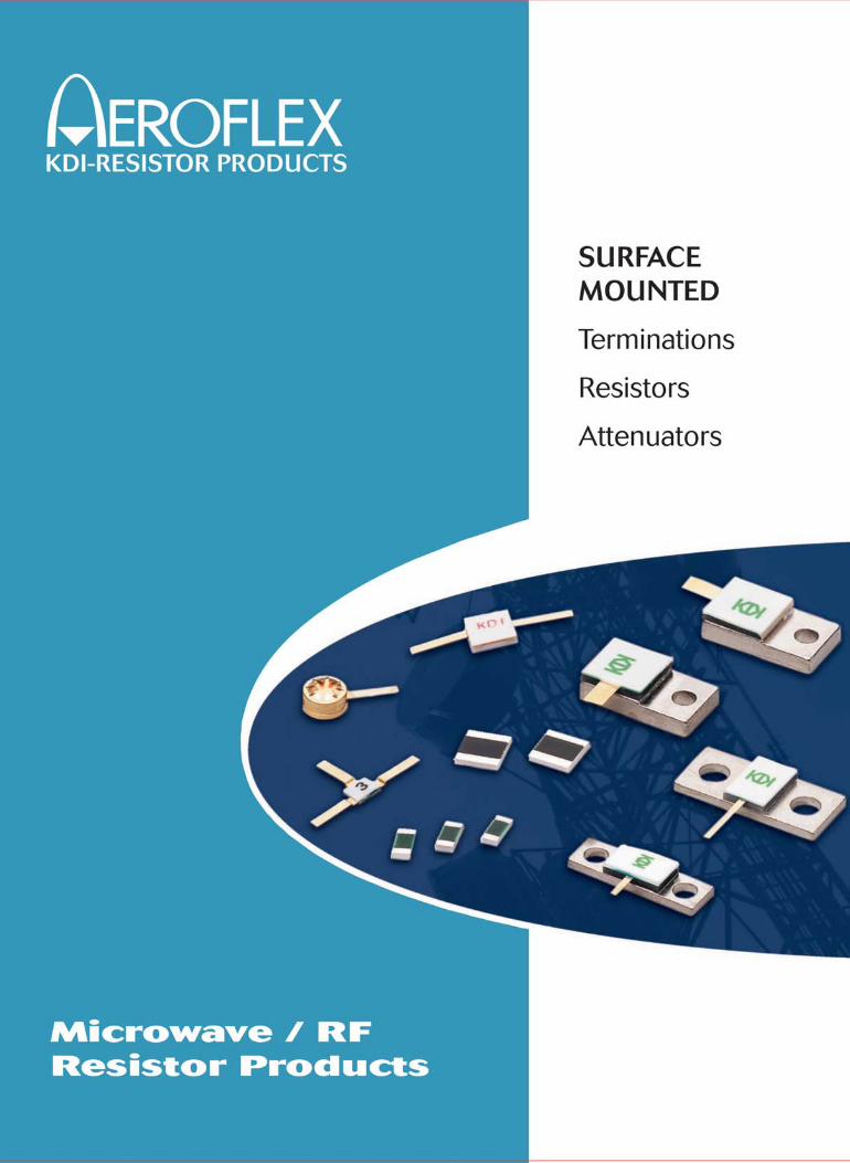
Focused on resistive film technologies,
AEROFLEX / KDI Resistor Products
offers a comprehensive variety of low
and high power surface mounted passive
devices for the wireless infrastructure and
defense markets. Applications for these
products include single and multi-carrier
power amplifiers, dividers/combiners,
isolators, circulators, and circuits requir-
ing stripline, microstrip and surface
mounted flange packages.
Recent technological advances in
materials and processes have enabled
AEROFLEX / KDI Resistor Products to
introduce environmentally safe aluminum
nitride (AlN) resistors, terminations and
attenuators designed as an alternative to
similar components using Beryllium oxide
(BeO) ceramic. Our product offering
includes flange mounted 50 and 100 Ohm
resistors and terminations with power han-
dling to 800 watts CW, coaxial cable load
assemblies, and attenuators in standard
values of 1-10, and 20 dB. AEROFLEX /
KDI Resistor Products also offers high
power chip devices, terminating attenua-
tors where low level signal sampling is
required, and drop-in pill type attenuators
and terminations.
AEROFLEX / KDI Resistor Products has
the technical capability and manufacturing
capacity to supply application specific,
high volume requirements for TDMA,
CDMA, 3G and LMDS technologies.
AEROFLEX / KDI Resistor Products is
located in Whippany, New Jersey and is
an ISO-9001:2000 certified supplier.
is built on a foundation of over 50 years of technological advances in both thin and
thick film components. A renewed FOCUS on Quality, Service, Innovation and Overall
Value to the customer is the basis of this dedicated group’s objectives.
AEROFLEX / KDI Resistor Products
Cable Load Assemblies
We offer a wide selection of “Cable LoadAssemblies,” made with a choice of eitherBeryllium Oxide (BeO) or Aluminum Nitride(AIN) resistive elements.
CW Power Levels range from 50 to 250watts and can be factory tuned for a VSWRas low as 1:04:1.
These Cable Load Assemblies feature semi-flexible cables in sizes of 0.080 and 0.141diameters with SMA style connectors asstandard. Other cable sizes and connectorsare also available.
Chip and Flanged Attenuators
We offer a wide selection of power chipand flanged attenuators for use in amplifiercircuits in both stripline and microstrippackages, as well as TerminatingAttenuators used in isolator designs where low level signal sampling is required. Attenuators are available in standard dB values of 1, 2, 3, 4, 5, 6, 10and 20. Other values may be requested.
All attenuator products are available in both Beryllium Oxide (BeO) or AluminumNitride (AIN).
Chip and Flanged Resistors and Terminations
We offer a wide variety of Chip and FlangedResistors and Terminations available inpower levels from 10 watts up to 800 wattsCW. All flanged devices are designed tooperate at full rated powers with the flange(heatsink) maintained at a maximum temperature of 100°C.
Resistors and Terminations are available in standard values of 50 and 100 ohms.Other values may be requested.
All Resistor and Termination Products areavailable in both Beryllium Oxide (BeO) orAluminum Nitride (AIN).
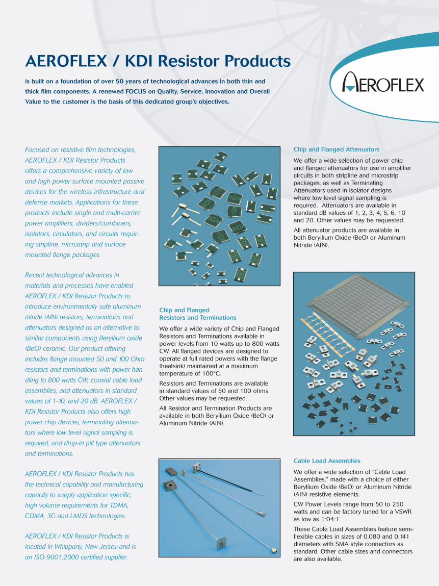
When mounting High Power Flange Devicesin a circuit, there are several key issues thatshould be taken into account.
Heat Sink DesignThe heat sink the device is mounted to mustbe designed to maintain the temperature(design) while it is dissipating the power(heat) given it by the device. (The deratingspecifications are given in the applicabledata sheets.)
Flatness of mating surfacesFlatness of the heat sink and of the mount-ing area of the device (flange) should be0.001” maximum. The idea is to have thebest possible contact between the heat sinkand the device.
Thermal CompoundTo fill any microscopic voids or air gaps theuse of thermal compound is recommendedto a thickness of 0.002” maximum.
Stress Relief on TabAlthough it is not always possible in HighFrequency applications a small loop forstress relief on the solder tab is recom-mended. This reduces any mechanicalstress on the joints.
Application Notes
This application note covers the recom-mended mounting techniques for the properconduction cooling and RF performance of a surface mounted (flangeless) chipattenuator, termination or resistor.
Initial ConsiderationsThere are two primary considerations for a surface mounted power device; PowerDissipation and RF Performance. In order to remove the dissipated power from thistype chip they must be provided with adequate conductive cooling. This will prevent excessive chip temperatures leading to damage and early failure of thedevice. RF performance is also dependenton proper mounting. Since these devicesare being mounted to a circuit board,inductance to ground is introduced by thevias to the ground plane. To reduce thiseffect and lower the thermal resistancebetween the component and ground plane,the following items are recommended:
1. Maximize the use of thermally conduc-tive vias around and under the device.
2. Use of heavy copper cladding (2 oz.) onthe circuit board as a heat spreader.
SoldersAeroflex-KDI recommends the use of thesolders in the chart below when installing asurface mount chip. Also listed are recom-mended platings for the heatsink/baseplatethat a device might be mounted to insteadof a circuit board.
MountingThe first step when mounting a chip deviceto the circuit board is to determine theproper size and location of the solderpads. Aeroflex-KDI recommends providingpads that are 0.010” to 0.020” over thedevice’s termination size and are centeredon the axis of the chip. This allows for self-centering of the chip and a proper solderfillet formation. Skewing and “tombstoning”can occur if this is not followed. See Figure 2
Apply a small amount of thermal compound to the mounting area of the flange of the device. Spread it completely on the flange using a razorblade or other smooth tool. When seatingthe device, align the tab/tabs over the corresponding area on the circuit board.Screw down the device using the recom-mended torque for the appropriate screwsize in the table below. Aeroflex-KDI recommends the use of a lock washer and a flat washer in the installation. See Figure 1
Solder the tab/tabs using SN62 (179° Ceutectic) solder and a small amount of RMA flux. After all the solder is complete all of the flux must now be removed using a cleaning agent.
TAB WITH STRESS RELIEF
THERMAL COMPOUND
DEVICE
HEATSINK
SUBSTRATE
Figure 1: High Power Flange Device Mounting
Thread Size Torque Setting
2-56 4 inch-pounds
4-40 6 inch pounds
6-32 8 inch pounds
8-32 12 inch pounds
10-32 18 inch pounds
Mounting of High Power Flange Devices Mounting of Chip Devices
KDI-RESISTOR PRODUCTS
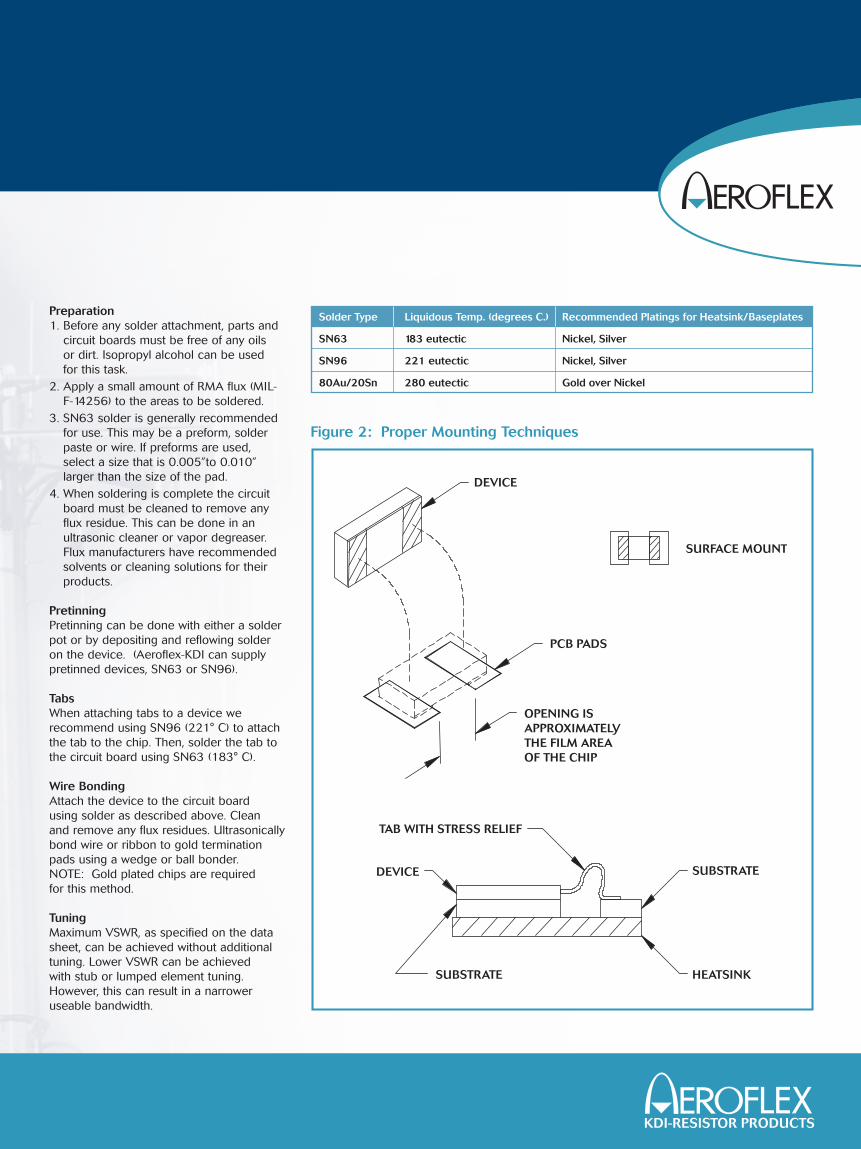
Preparation1. Before any solder attachment, parts and
circuit boards must be free of any oils or dirt. Isopropyl alcohol can be used for this task.
2. Apply a small amount of RMA flux (MIL-F-14256) to the areas to be soldered.
3. SN63 solder is generally recommendedfor use. This may be a preform, solderpaste or wire. If preforms are used,select a size that is 0.005”to 0.010” larger than the size of the pad.
4. When soldering is complete the circuitboard must be cleaned to remove anyflux residue. This can be done in anultrasonic cleaner or vapor degreaser.Flux manufacturers have recommendedsolvents or cleaning solutions for theirproducts.
PretinningPretinning can be done with either a solderpot or by depositing and reflowing solderon the device. (Aeroflex-KDI can supplypretinned devices, SN63 or SN96).
TabsWhen attaching tabs to a device we recommend using SN96 (221° C) to attachthe tab to the chip. Then, solder the tab tothe circuit board using SN63 (183° C).
Wire BondingAttach the device to the circuit board using solder as described above. Clean and remove any flux residues. Ultrasonicallybond wire or ribbon to gold terminationpads using a wedge or ball bonder. NOTE: Gold plated chips are required for this method.
TuningMaximum VSWR, as specified on the datasheet, can be achieved without additionaltuning. Lower VSWR can be achieved with stub or lumped element tuning.However, this can result in a narrower useable bandwidth.
TAB WITH STRESS RELIEF
DEVICE
DEVICE
PCB PADS
SURFACE MOUNT
OPENING ISAPPROXIMATELYTHE FILM AREAOF THE CHIP
HEATSINK
SUBSTRATE
SUBSTRATE
Figure 2: Proper Mounting Techniques
Solder Type Liquidous Temp. (degrees C.) Recommended Platings for Heatsink/Baseplates
SN63 183 eutectic Nickel, Silver
SN96 221 eutectic Nickel, Silver
80Au/20Sn 280 eutectic Gold over Nickel
KDI-RESISTOR PRODUCTS

Aeroflex Microelectronic Solutions
AEROFLEX / KDI Resistor Products Whippany, NJ
Aluminum Nitride (AlN) and Beryllium Oxide (BeO) chip and flange mounted, high power fixed attenuators, resistors and terminations, custom thick and thin film devices and cable load assemblies designed and manufactured for applications in
isolator / circulators, single and multi-carrier power amplifiers, dividers, combiners, phased arrays, and other wirelessinfrastructure and defense markets. Aeroflex / KDI Resistor Products is an ISO 9001:2000 certified supplier.
AEROFLEX / KDI Integrated Products Whippany, NJ
Base Station Transmit Converters, switch matrices, BTS RF diagnostics, E911 expansion kits, vector modulators, phase shifters, switches, digital attenuators, voltage variable attenuators, up / down
converters, power combiners, dividers and couplers, switched time delay units, multi-function subassemblies, RF front ends, switched filter banks, cavity filters, diplexers, multiplexers and
custom RF subassemblies for wireless, military and space applications. Aeroflex / KDI Integrated Products is certified to ISO 9001:2000.
AEROFLEX / Inmet Ann Arbor, MI
Designs and manufactures a wide array of precision and low cost coaxial components in a variety of connector types that operate in frequency ranges from 7 kHz to 65 GHzwith power handling capabilities up to 300 watts. Product offerings include over 3,000variations of coaxial attenuators, terminations, bias tees, dc blocks, in-series andbetween-series adapters, connectors, fixed and adjustable gain equalizers and connectors. Aeroflex / Inmet is an ISO 9001:2000 certified supplier.
AEROFLEX / Metelics Sunnyvale, CA
Manufacturer of the highest performance diode products available to the commercialwireless, defense, space and broadband industries. Aeroflex / Metelics offers acomplete product range of PIN and Schottky diodes, tunnel diodes, step recoverydiodes ( SRD ), tuning varactor diodes, sampling phase detectors, MIS capacitors,and their new line of HPT Amplifiers ideally suited for cellular, PCS, 2.5/3G, MMDS,WLL and other types of wireless infrastructure applications where flat gain andgood linearity are required. This facility is certified to ISO 9001:2000 standards.
AEROFLEX / Weinschel Frederick, MD
Product offerings include fixed attenuators for test, metrology and space applications; continuously variable, manual step, solid-state digital step and programmable step attenuators; resistive splitters and dividers; manual phaseshifters. In addition to coaxial components up to 40 GHz, Aeroflex / Weinscheloffers a complete range of standard and custom designed multi-path switching,combining, and attenuation subsystems for cable infrastructure and mobile wire-less test applications. This facility is ISO 9001:2000 certified.
AEROFLEX / Plainview Plainview, NY
This division has developed ultra broadband modulator driver amplifiers, limitingamplifiers, and clock drivers for the Fiber Optic communications market. These
components operate over the frequency ranges of 30 KHz to 50 GHz and are highly integrated to achieve higher performance, smaller size and lower cost.
Aeroflex Plainview has leveraged their vast microwave design library and manufacturing experience to offer a wide variety of state-of-the-art broadband
power amplifiers, LNAs, mixers and highly integrated RF modules for the military, commercial and aerospace markets. This facility is ISO 9000:2000; AS 9100-2000certified and MIL-PRF-38534 Class K, H and E certified.
Aeroflex, Inc. is
a multi-faceted high
technology company that
designs, develops, manufactures
and markets a diverse range of
microelectronic, test and measurement
products. Aeroflex products are in
worldwide use supporting communication
systems, networks and automatic test
systems. The success of Aeroflex in the
semiconductor market is attributed to their
space qualified and radiation hardened
products used in satellite communications.
Their cost efficient process for producing
semiconductors capable of operating in the
harsh environment of space has clearly
demonstrated its merits and has a history
of proven accomplishments. In an industry
that must use trustworthy processes and
vendors, Aeroflex believes that they
are in the enviable position of having
built an unimpeachable reputation
for quality and reliability while
having the requisite heritage
of space experience.
Aeroflex Microelectronic Solutions is a growing and vital technology leader in the worldwide marketplacethat stresses innovative solution-minded products. The acquisition of MCE Technologies and integrationinto the Aeroflex Microelectronic Solutions group firmly established the company as one of industry’smost complete suppliers of RF, microwave and millimeter wave devices, components and subsystems.Our broad offering of standard products, innovative, custom-engineered designs, and comprehensiveresources enable Aeroflex to support the most demanding high-performance, high-quality, product needs of our customers.
Aeroflex Microelectronic Solutions microwave products consist of strategically aligned operating unitswith locations throughout North America. They include:
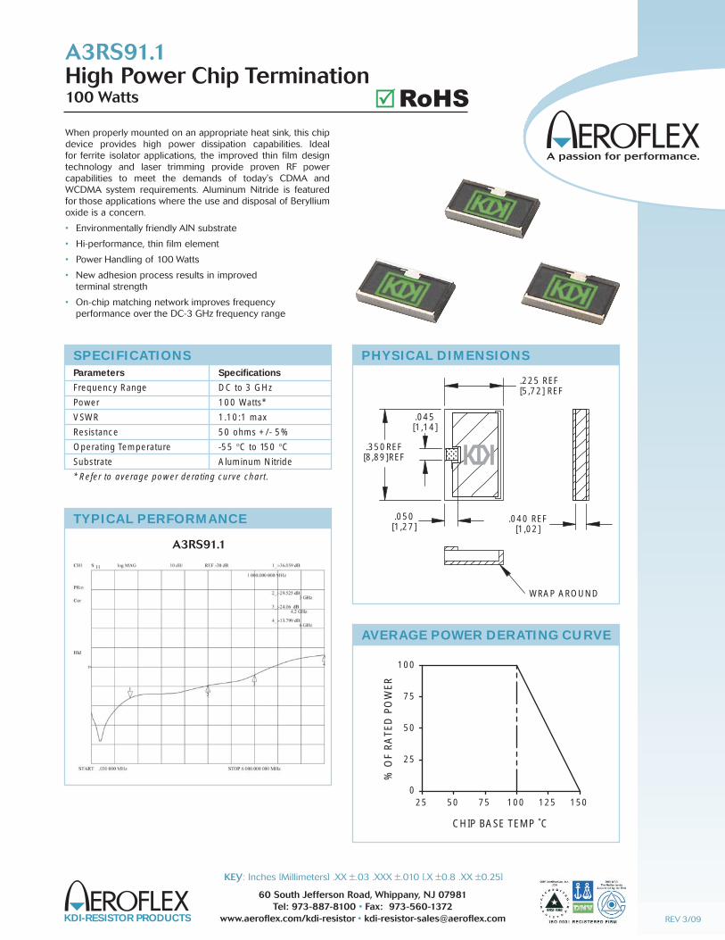
When properly mounted on an appropriate heat sink, this chipdevice provides high power dissipation capabilities. Ideal for ferrite isolator applications, the improved thin film designtechnology and laser trimming provide proven RF power capabilities to meet the demands of today's CDMA andWCDMA system requirements. Aluminum Nitride is featuredfor those applications where the use and disposal of Berylliumoxide is a concern.
• Environmentally friendly AlN substrate
• Hi-performance, thin film element
• Power Handling of 100 Watts
• New adhesion process results in improved terminal strength
• On-chip matching network improves frequency performance over the DC-3 GHz frequency range
SPECIFICATIONS
Parameters Specifications
Frequency Range DC to 3 GHz
Power 100 Watts*
VSWR 1.10:1 max
Resistance 50 ohms +/- 5%
Operating Temperature -55 °C to 150 °CSubstrate Aluminum Nitride
* Refer to average power derating curve chart.
.225 REF[5,72] REF
.350REF[8,89]REF
.040 REF[1,02]
WRAP AROUND
.045[1,14]
.050[1,27]
PHYSICAL DIMENSIONS
CHIP BASE TEMP ˚C
% O
F R
ATE
D P
OW
ER
25
250
50
50
75 100
75
100
125 150
AVERAGE POWER DERATING CURVE
TYPICAL PERFORMANCE
A3RS91.1High Power Chip Termination100 Watts
A3RS91.1
KDI-RESISTOR PRODUCTS
60 South Jefferson Road, Whippany, NJ 07981Tel: 973-887-8100 • Fax: 973-560-1372
www.aeroflex.com/kdi-resistor • [email protected]
KEY: Inches [Millimeters] .XX ±.03 .XXX ±.010 [.X ±0.8 .XX ±0.25]
REV 3/09
RoHS��
KDI-RESISTOR PRODUCTS
60 South Jefferson Road, Whippany, NJ 07981Tel: 973-887-8100 • Fax: 973-560-1372
www.aeroflex.com/kdi-resistor • [email protected]
KEY: Inches [Millimeters] .XX ±.03 .XXX ±.010 [.X ±0.8 .XX ±0.25]
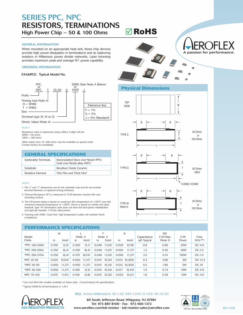
GENERAL INFORMATIONWhen mounted on an appropriate heat sink, these chip devices provide high power dissipation in terminations and as balancingresistors in Wilkenson power divider networks. Laser trimmingprovides maximum peak and average R.F. power capability.
ORDERING INFORMATION
SERIES PPC, NPCRESISTORS, TERMINATIONSHigh Power Chip – 50 & 100 Ohms
NOTES
1. The “L” and “T” dimensions are for the substrate only and do not include terminal thickness or optional tinning thickness.
2. Thermal Resistance (R°) is measured in °C/W between resistive film and mounting surface.
3. The CW power rating is based on maximum film temperature of +150°C and with maximum heatsink temperature of +100°C. Power is based on infinite and idealheatsink. Type “W” termination style does not have full back plane metallization and typically handles 1/10 the rated power.
4. Tinnning with SN96 “Lead Free” high temperature solder will maintain RoHscompliance.
GENERAL SPECIFICATIONS
Solderable Terminals Electroplated Silver over Nickel (PPC) Gold over Nickel alloy (NPC)
Substrate Beryllium Oxide Ceramic
Resistive Element Thin Film and Thick Film*
EXAMPLE: Typical Model No.
NPC T 25-50 X J
Prefix
Tinning (see Note 4)H = SN96T = SN62
Size
Terminal type (X, W or G)
Ohmic Value (Note A)
50R0or
1000
PPCor
NPC X
Tolerance Key
F = 1%G = 2%J = 5% (Standard)
(See Note A Below)
W L T B RØModel (Note 1) (Note 1) Capacitance C/W Max. C/W Freq.Prefix in [mm] in [mm] in [mm] in [mm] (pf) Typical (Note 2) Power GHz (**)
*PPC 100-200A 0.100 [2,5] 0.200 [5,1] 0.040 [1,02] 0.030 [0,76] 0.8 0.80 20W DC-4.0
*PPC 250-250A 0.250 [6,4] 0.250 [6,4] 0.040 [1,02] 0.050 [1,27] 1.2 0.30 40W DC-2.5
*PPC 250-375A 0.250 [6,4] 0.375 [9,53] 0.040 [1,02] 0.050 [1,27] 3.5 0.15 150W DC-1.0
NPC 25-50 0.025 [0,64] 0.050 [1,27] 0.010 [0,25] 0.012 [0,305] 0.3 3.90 3W DC-12.4
*NPC 50-50 0.050 [1,27] 0.050 [1,27] 0.010 [0,25] 0.012 [0,305] 0.5 1.90 5W DC-10
*NPC 50-100 0.050 [1,27] 0.100 [2,5] 0.010 [0,25] 0.017 [0,43] 1.0 0.72 10W DC-4.0
NPC 75-150 0.075 [1,91] 0.150 [3,8] 0.010 [0,25] 0.020 [0,51] 1.8 0.29 15W DC-4.0
PERFORMANCE SPECIFICATIONS
NOTE A
Resistance value is expressed using military 4-digit call-out.50R0 = 50 ohms1000 = 100 ohms
Other values from 10–500 ohms may be available as special order.Contact factory for availability.
Physical Dimensions
TOPVIEW W
B
T
L
B
TYPE X
B
T
L
B
TYPE G
50 Ohmsor
100 Ohms
50 OhmsONLY
50 Ohmsor
100 Ohms
B
T
L
B
TYPE W(Note 3)
0.005[0.13] MAX
* Low cost thick film models available on these sizes. Consult factory for specifications.
** Typical VSWR for all terminations is 1.25:1
REV 3/09
RoHS��
KDI-RESISTOR PRODUCTS
60 South Jefferson Road, Whippany, NJ 07981Tel: 973-887-8100 • Fax: 973-560-1372
www.aeroflex.com/kdi-resistor • [email protected]
KEY: Inches [Millimeters] .XX ±.03 .XXX ±.010 [.X ±0.8 .XX ±0.25]
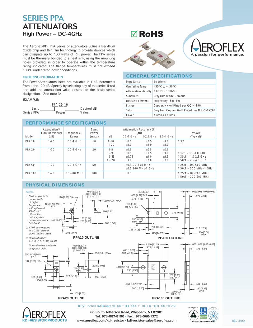
The Aeroflex/KDI PPA Series of attenuators utilize a BerylliumOxide chip and thin film technology to provide devices whichcan dissipate up to 100 watts of R.F. power. The PPA seriesmust be thermally bonded to a heat sink, using the mountingholes provided, in order to operate within the temperature rating indicated. The flange temperatures must not exceed100°C under rated power conditions.
ORDERING INFORMATIONThe Power Attenuators listed are available in 1 dB incrementsfrom 1 thru 20 dB. Specify by selecting any of the series listedand add the attenuation value desired to the basic series designation. (See note 3)
SERIES PPAATTENUATORSHigh Power – DC-4GHz
GENERAL SPECIFICATIONS
Impedance 50 Ohms
Operating Temp. –55°C to +150°C
Attenuation Stability 0.0001 dB/dB/°C
Substrate Beryllium Oxide Ceramic
Resistive Element Proprietary Thin Film
Flange Copper, Nickel Plated per QQ-N-290
Tabs Beryllium Copper, Gold Plated per MIL-G-45204
Cover Alumina Ceramic
.062 [1.58]
.040 [1.02] x.005±.001 THK
[0.13±0.03]
.300 [7.62]
.160 [4.06] MAX.
.105 [2.67]
.100 [2.54].100 [2.54].200 [5.08]
.125 [3.18] MIN. TYP
PPA10 OUTLINE
.116 [2.95] DIA.
.062 [1.58]
.060 [1.52] x.003±.001 THK
[0.08±0.03]
.515 [13.08]
.150 [3.81] MAX.
.105 [2.67]
.250 [6.35].125 [3.18] .125 [3.18]
.250 [6.35] MIN. TYP
PPA20 OUTLINE
.250 [6.35]MIN
.116 [2.95] DIA.
.003±.001 [0.08±0.03]
.110 [2.79].125 [3.18].725 [18.42]
.975 [24.77]
.175 [4.45].060 [1.52] TYP
.375 [9.52]
.375 [9.53]
.250 [6.35]MIN TYP
PPA50 OUTLINE
.171 [4.34]
.200 [5.08]MAX
.125 [3.18]THRU 2 PLS
.003±.001 [0.08±0.03]
.210 [5.33]MAX
.125 [3.18]
.250 [6.35]MIN TYP
.500 [12.70]
.060 [1.52] TYP
1.250 [31.75].875 [22.23]
.188 [4.76].405 [10.29]
.250 [6.35].500 [12.70]
PPA100 OUTLINE
.171 [4.34]
.160 [4.06]THRU PLS
PHYSICAL DIMENSIONS
Attenuation(1) Input Attenuation Accuracy (1) 1 dB Increments Frequency(1) Power (dB) VSWRModel (dB) Range (Watts) dB DC-1 GHz 1-2.5 GHz 2.5-4 GHz (Typical)2
PPA 10 1-20 DC-4 GHz 10 1-10 ±0.5 ±0.5 ±1.0 1.3:1 11-20 ±1.0 ±2.0 ±3.0
PPA 20 1-20 DC-4 GHz 20 1-5 ±0.5 ±0.5 ±0.5 6-9 ±0.5 ±0.5 ±1.0 1.15:1 – DC-1.0 GHz 10-15 ±0.75 ±1.0 ±1.5 1.35:1 – 1.0-2.5 GHz 16-20 ±1.0 ±2.0 ±3.0 1.50:1 – 2.5-4.0 GHz
PPA 50 1-20 DC-1 GHz 50 ±0.3 DC-500 MHz 1.25:1 – DC-500 MHz ±0.5 500 MHz-1 GHz 1.50:1 – 500 MHz–1 GHz
PPA 100 1-20 DC-500 MHz 100 ±0.5 1.25:1 – DC-200 MHz 1.50:1 – 200-500 MHz
PERFORMANCE SPECIFICATIONS
EXAMPLE:
PPA 20-10Desired dBValue
BasicSeries PPA Power
NOTES
1. Custom products are available at higher frequencies with optimized VSWR and attenuation accuracy over narrow frequency bandwidths.
2. VSWR as measured in a 0.125” ground plane stripline circuit.
3. Standard values 1, 2, 3, 4, 5, 6, 10, 20 dB.
Non-std values availableas special order.
REV 3/09
RoHS��

SERIES PMS, PPR, PPTRESISTORS & TERMINATIONSHigh Power, Thin Film, Drop-in – 10-650 Watts, DC-4 GHz
NOTES
1. Input power ratings are based on flange temperature of 100° C maximum.
2. 50 and 100 Ohms standard. Other values from 10-500 ohms available onspecial order. Contact factory for details. Standard tolerance ±5%. Specify resistance value when ordering.
3. VSWR applies to termination style only.
GENERAL SPECIFICATIONSResistive Element Thin Film and Thick Film*Substrate Beryllium Oxide CeramicCover Alumina CeramicMounting Flange Copper,Nickel Plated per QQ-N-290Tab Beryllium Copper,Gold Plated per MIL-G-45204
AVERAGE POWER DERATING CURVE
FLANGE TEMPERATURE — °C
POWER DERATING
% O
F R
ATE
D P
OW
ER 100
100 125 150
75
75
50
50
25
250
Frequency Input Power VSWR (Typical) Capacitance Figure Model Range (Watts Avg.) (Note 3) (pF) (Typ.) No.PPR & PPT 300-10-3* DC-4.0 GHz 10 1.35:1 —DC-4.0 GHz 0.8 1PMS-100 & PMS-200* DC-2.0 GHz 20 1.25:1 —DC-2.0 GHz 1.2 2PPR & PPT 515-20-3* DC-2.0 GHz 20 1.10:1 —DC-1.0 GHz 0.8 3 1.25:1 —1.0-2.0 GHzPPT515-30-4 DC-4.0 GHz 30 1.20:1 —DC-4 GHz 1.2 4PPR & PPT 515-30* DC-2.0 GHz 30 1.10:1 —DC-1.0 GHz 0.8 5 1.25:1 —1.0-2.0 GHzPPR & PPT 800-40-3 DC-4.0 GHz 40 1.25:1 —DC-4.0 GHz 1.4 6PPT800-100A DC-2.0 GHz 100 1.25:1 —DC-2.0 GHz 1.4 7PPR & PPT 870-150-3* DC-1.0 GHz 150 1.20:1 —DC-500 MHz 3.5 8 1.35:1 —500-1000 MHzPPR & PPT 975-250-3 DC-1.0 GHz 250 1.25:1 —DC-500 MHz 5.0 9 1.35:1 —500-1000 MHzPPR & PPT 1250-400 DC-500 MHz 400 1.50:1 —DC-500 MHz 7.0 10PPR &PPT 1900-800 DC-500 MHz 650 1.25:1 —DC-200 MHz 10.2 11 1.50:1 —200-500 MHz
PERFORMANCE SPECIFICATIONS
GENERAL INFORMATIONThese high power devices are designed to dissipate power inR.F. circuits when mounted to an appropriate heat sink. The ter-minations provide a low VSWR under maximum power condi-tions. The resistor configurations are typically used in“Wilkinson” type power divider networks, or to terminate 3 dBstripline or microstrip hybrids.
* Low cost thick film models available on some sizes.Consult Factory for specifications.
TERMINATIONS (PPT) SERIES RESISTORS (PPR) SERIES FIGURES
PPT 300-10-3 — 10 WATTSFlange Mounted
PPR 300-10-3 — 10 WATTSFlange Mounted
FIG. 1
PMS 100 — 20 WATTSStud Mounted
PMS 200 — 20 WATTSStud Mounted
FIG. 2
.062 [1.57]
.100 [2.54]
.100 [2.54]
.200 [5.08]
.300 [7.62]
.200 [5.08]
.005±.001 [0.13±0.03]
.110 [2.79].030 [0.76]
.040 [1.02].125 [3.17] MIN
.160 [4.06]MAX
.116 [ 2.95]
.060[1.52] MAX.
.250[6.4]
.250[6.4]
.065[1.65]TYP.
.092[2.34]TYP..062
[1.57]
.375[9.53]
.032[0.81] WIDEX .035[0.89] DEEP SLOT
6-32 NC-2A THD
.500±.015[12.7±0.38]
TYP.
.003±.001[0.08±0.03]
PHYSICAL DIMENSIONS
TERMINATIONS (PPT) SERIES RESISTORS (PPR) SERIES FIGURES
REV 3/09KEY: Inches [Millimeters] .XX ±.03 .XXX ±.010 [.X ±0.8 .XX ±0.25]
RoHS��
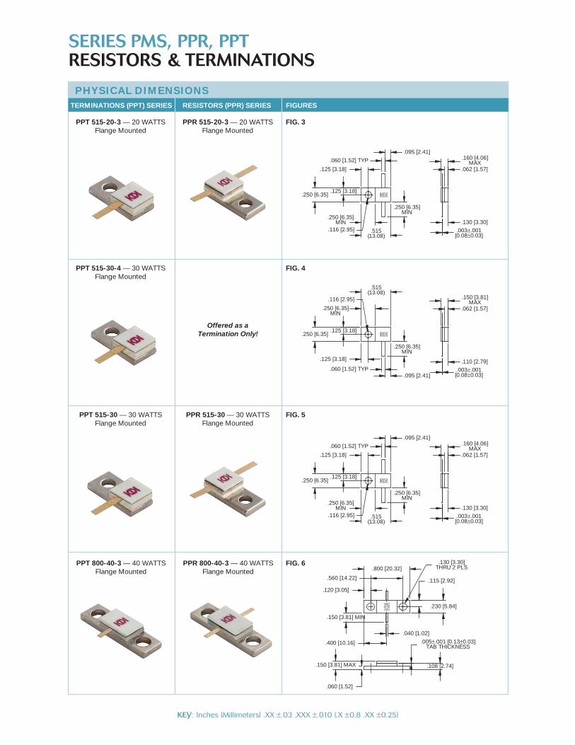
FIG. 3PPT 515-20-3 — 20 WATTSFlange Mounted
PPR 515-20-3 — 20 WATTSFlange Mounted
FIG. 5PPT 515-30 — 30 WATTSFlange Mounted
PPR 515-30 — 30 WATTSFlange Mounted
FIG. 4PPT 515-30-4 — 30 WATTSFlange Mounted
Offered as aTermination Only!
.005±.001 [0.13±0.03]TAB THICKNESS
.040 [1.02]
.560 [14.22]
.800 [20.32]
.108 [2.74]
.060 [1.52]
.150 [3.81] MAX
.150 [3.81] MIN
.400 [10.16]
.120 [3.05]
.115 [2.92]
.230 [5.84]
.130 [3.30]THRU 2 PLS
PPT 800-40-3 — 40 WATTSFlange Mounted
PPR 800-40-3 — 40 WATTSFlange Mounted
FIG. 6
TERMINATIONS (PPT) SERIES RESISTORS (PPR) SERIES FIGURES
PHYSICAL DIMENSIONS
TERMINATIONS (PPT) SERIES RESISTORS (PPR) SERIES FIGURES
.003±.001[0.08±0.03]
.130 [3.30]
.062 [1.57]
.160 [4.06]MAX
.250 [6.35]
.125 [3.18]
.125 [3.18]
.060 [1.52] TYP
.095 [2.41]
.250 [6.35]MIN
.515(13.08)
.250 [6.35]MIN
.116 [2.95]
.003±.001[0.08±0.03]
.130 [3.30]
.062 [1.57]
.160 [4.06]MAX
.250 [6.35]
.125 [3.18]
.125 [3.18]
.060 [1.52] TYP
.095 [2.41]
.250 [6.35]MIN
.515(13.08)
.250 [6.35]MIN
.116 [2.95]
.003±.001[0.08±0.03]
.110 [2.79]
.062 [1.57]
.150 [3.81]MAX
.250 [6.35]
.125 [3.18]
.125 [3.18]
.060 [1.52] TYP.095 [2.41]
.250 [6.35]MIN
.515(13.08)
.250 [6.35]MIN
.116 [2.95]
SERIES PMS, PPR, PPTRESISTORS & TERMINATIONS
KEY: Inches [Millimeters] .XX ±.03 .XXX ±.010 [.X ±0.8 .XX ±0.25]
.003±.001 [0.08±0.03]
.062 [1.57]
.155 [3.94]
.160 [4.06] MAX
.187 [4.76]
.375 [9.52]
.120 [3.05]
.250 [6.35]
.560 [14.22].870 [22.10]
.125 [3.18] MIN
.108 [2.74]
.161 [4.09]THRU 2 PLS
TERMINATIONS (PPT) SERIES RESISTORS (PPR) SERIES FIGURES
PHYSICAL DIMENSIONS
TERMINATIONS (PPT) SERIES RESISTORS (PPR) SERIES FIGURES
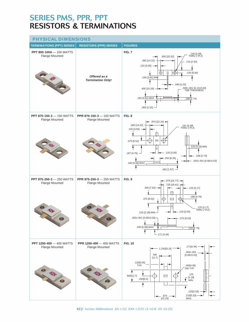
FIG. 8
FIG. 9
PPT 870-150-3 — 150 WATTSFlange Mounted
PPR 870-150-3 — 150 WATTSFlange Mounted
PPT 975-250-3 — 250 WATTSFlange Mounted
PPR 975-250-3 — 250 WATTSFlange Mounted
PPT 1250-400 — 400 WATTSFlange Mounted
PPR 1250-400 — 400 WATTSFlange Mounted
FIG. 10
.005±.001 [0.13±0.03]TAB THICKNESS
.040 [1.02]
.560 [14.22]
.800 [20.32]
.108 [2.74]
.060 [1.52]
.150 [3.81] MAX
.150 [3.81] MIN
.400 [10.16]
.120 [3.05]
.115 [2.92]
.230 [5.84]
.130 [3.30]THRU 2 PLS
FIG. 7
Offered as a Termination Only!
PPT 800-100A — 100 WATTSFlange Mounted
.200 [5.08] MAX
.375 [9.53]
.110 [2.79]
.300 [7.62]
.125 [3.18] MIN
.975 [24.77]
.375 [9.52]
.725 [18.41]
.120 [3.05]
.125 [3.17]
.171 [4.34]
.125 [3.17]THRU 2 PLS
.188 [4.76]
.003±.001 [0.08±0.03]
.500[12.7]
1.250[31.8]
.125[3.18]MIN.
500[12.7].250[6.4]
.875[22.23]
.120[3.05]TYP. .160[4.06]
DIA TYP.
.125[3.18]
.210[5.33] MAX.
.171[4.34]
.003±.001[0.08±0.03]
SERIES PMS, PPR, PPTRESISTORS & TERMINATIONS
KEY: Inches [Millimeters] .XX ±.03 .XXX ±.010 [.X ±0.8 .XX ±0.25]
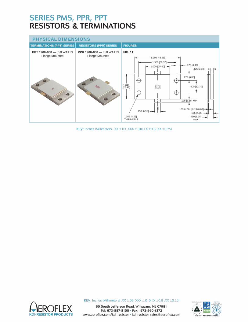
FIG. 11PPT 1900-800 — 650 WATTSFlange Mounted
PPR 1900-800 — 650 WATTSFlange Mounted
.125 [3.18] MIN
.250 [6.35]
1.550 [39.37]
1.000 [25.40]
1.900 [48.26]
1.040[26.42]
.175 [4.45]
.500 [12.70]
.270 [6.86]
LC
.195 [4.95]
.125 [3.18]
.166 [4.22]THRU 4 PLS
.005±.001 [0.13±0.03]
.250 [6.35]MAX
TERMINATIONS (PPT) SERIES RESISTORS (PPR) SERIES FIGURES
PHYSICAL DIMENSIONS
TERMINATIONS (PPT) SERIES RESISTORS (PPR) SERIES FIGURES
SERIES PMS, PPR, PPTRESISTORS & TERMINATIONS
KEY: Inches [Millimeters] .XX ±.03 .XXX ±.010 [.X ±0.8 .XX ±0.25]
KDI-RESISTOR PRODUCTS
60 South Jefferson Road, Whippany, NJ 07981Tel: 973-887-8100 • Fax: 973-560-1372
www.aeroflex.com/kdi-resistor • [email protected]
KEY: Inches [Millimeters] .XX ±.03 .XXX ±.010 [.X ±0.8 .XX ±0.25]

KDI-RESISTOR PRODUCTS
60 South Jefferson Road, Whippany, NJ 07981Tel: 973-887-8100 • Fax: 973-560-1372
www.aeroflex.com/kdi-resistor • [email protected]
KEY: Inches [Millimeters] .XX ±.03 .XXX ±.010 [.X ±0.8 .XX ±0.25]
GENERAL INFORMATIONAeroflex/KDI Cartridge Terminations are miniature, space savingmodels with high power capability to 15 watts.
The PCL Series incorporates an alignment slot to assist in accu-rate positioning when soldering to a stripline or microstrip circuit.
PCL SERIES FEATURES• Alignment Slot
• Weight less than 2 grams
• Space Saver-Compact size
MATERIALSHousing: Copper, Nickel Plated per QQ-N-290
Tab: Beryllium Copper, Gold Plated per MIL-G-45204
SERIES PCLTERMINATIONSCartridge – DC-18 GHz
NOTE
1. VSWR as measured in a 50 ohm stripline circuit.PHYSICAL DIMENSIONS
PCL3-125-3 Outline
PCL15-250-1 Outline
.260[6.6]
.010[0.25]
.020[0.51]R
.003±.001 [0.08±0.03]
.060[1.52]
.200[5.1]MIN
.015[0.38]
.250±.001[6.35±0.03]
.125±.001[3.18±0.03]
ALIGNMENT SLOT
ALIGNMENT SLOT
.015[0.38]
.185[4.7]
.200[5.1]MIN
.060[1.52]
.003±.001 [0.08±0.03]
.010[0.25]
.020[0.51]R
AVERAGE POWER DERATING CURVE
CASE TEMPERATURE — °C
POWER DERATING
% O
F R
ATE
D P
OW
ER
100
100 125 150
75
75
50
50
25
250
Input Part Frequency Power Number Range (Watts) VSWR (Typical)(1)
PCL3-125-3 DC-18 GHz 3 DC-4 GHz—1.10:1 4-8 GHz—1.20:1 8-12.4 GHz—1.30:1 12.4-18 GHz—1.50:1
PCL15-250-1 DC-12.4 GHz 15 DC-4 GHz—1.10:1 4-8 GHz—1.20:1 8-12.4 GHz—1.30:1
PERFORMANCE SPECIFICATIONS
TYPICAL PERFORMANCE
FREQUENCY (GHz)
PCL3-125-3
RE
TUR
N L
OS
S (d
B)
LIMITS
TYPICAL
10
20
30
40
50
60100 20
REV 3/09
RoHS��
FEATURES• Laser Trimmed• Temperature Stable
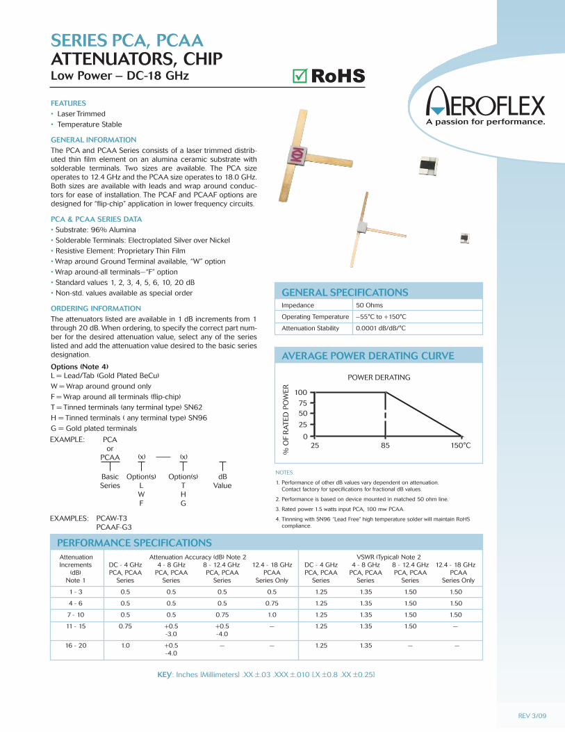
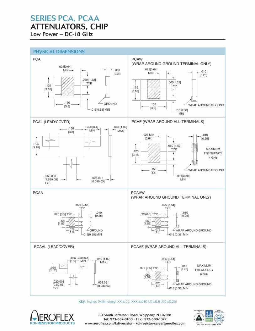
GENERAL INFORMATIONThe PCA and PCAA Series consists of a laser trimmed distrib-uted thin film element on an alumina ceramic substrate withsolderable terminals. Two sizes are available. The PCA sizeoperates to 12.4 GHz and the PCAA size operates to 18.0 GHz.Both sizes are available with leads and wrap around conduc-tors for ease of installation. The PCAF and PCAAF options aredesigned for “flip-chip” application in lower frequency circuits.
PCA & PCAA SERIES DATA• Substrate: 96% Alumina• Solderable Terminals: Electroplated Silver over Nickel• Resistive Element: Proprietary Thin Film• Wrap around Ground Terminal available, “W” option• Wrap around-all terminals—“F” option• Standard values 1, 2, 3, 4, 5, 6, 10, 20 dB• Non-std. values available as special order
ORDERING INFORMATIONThe attenuators listed are available in 1 dB increments from 1through 20 dB. When ordering, to specify the correct part num-ber for the desired attenuation value, select any of the serieslisted and add the attenuation value desired to the basic seriesdesignation.
Options (Note 4)L = Lead/Tab (Gold Plated BeCu)W = Wrap around ground onlyF = Wrap around all terminals (flip-chip)T = Tinned terminals (any terminal type) SN62H = Tinned terminals ( any terminal type) SN96G = Gold plated terminals
SERIES PCA, PCAAATTENUATORS, CHIPLow Power – DC-18 GHz
NOTES
1. Performance of other dB values vary dependent on attenuation. Contact factory for specifications for fractional dB values.
2. Performance is based on device mounted in matched 50 ohm line.
3. Rated power 1.5 watts input PCA, 100 mw PCAA.
4. Tinnning with SN96 “Lead Free” high temperature solder will maintain RoHScompliance.
GENERAL SPECIFICATIONSImpedance 50 Ohms
Operating Temperature –55°C to +150°C
Attenuation Stability 0.0001 dB/dB/°C
EXAMPLE:
EXAMPLES:
PCAor
PCAA (x)
Option(s)LWF
BasicSeries
PCAW-T3PCAAF-G3
(x)
Option(s)THG
dBValue
AVERAGE POWER DERATING CURVE
25
100
7550
25
085 150°C
POWER DERATING
% O
F R
ATE
D P
OW
ER
Attenuation Attenuation Accuracy (dB) Note 2 VSWR (Typical) Note 2 Increments DC - 4 GHz 4 - 8 GHz 8 - 12.4 GHz 12.4 - 18 GHz DC - 4 GHz 4 - 8 GHz 8 - 12.4 GHz 12.4 - 18 GHz (dB) PCA, PCAA PCA, PCAA PCA, PCAA PCAA PCA, PCAA PCA, PCAA PCA, PCAA PCAA Note 1 Series Series Series Series Only Series Series Series Series Only
1 - 3 0.5 0.5 0.5 0.5 1.25 1.35 1.50 1.50
4 - 6 0.5 0.5 0.5 0.75 1.25 1.35 1.50 1.50
7 - 10 0.5 0.5 0.75 1.0 1.25 1.35 1.50 1.50
11 - 15 0.75 +0.5 +0.5 — 1.25 1.35 1.50 — -3.0 -4.0
16 - 20 1.0 +0.5 — — 1.25 1.35 — — -4.0
PERFORMANCE SPECIFICATIONS
REV 3/09
KEY: Inches [Millimeters] .XX ±.03 .XXX ±.010 [.X ±0.8 .XX ±0.25]
RoHS��
SERIES PCA, PCAAATTENUATORS, CHIPLow Power – DC-18 GHz
KDI-RESISTOR PRODUCTS
60 South Jefferson Road, Whippany, NJ 07981Tel: 973-887-8100 • Fax: 973-560-1372
www.aeroflex.com/kdi-resistor • [email protected]
KEY: Inches [Millimeters] .XX ±.03 .XXX ±.010 [.X ±0.8 .XX ±0.25]
PHYSICAL DIMENSIONS
PCA
PCAA
PCAAL (LEAD/COVER)
PCAL (LEAD/COVER)
PCAW(WRAP AROUND GROUND TERMINAL ONLY)
PCAF (WRAP AROUND ALL TERMINALS)
PCAAF (WRAP AROUND ALL TERMINALS)
PCAAW(WRAP AROUND GROUND TERMINAL ONLY)
.025[0.64]MIN
.060 [1.52]TYP.
.015[0.38] MIN
.150[3.8]
.010[0.25]
GROUND
.125[3.18]
.150[3.8]
.125[3.18]
.250 [6.4]MIN
.060.003[1.520.08]TYP.
.003.001[0.080.03]
.040 [1.02]MAX
.060[1.52]TYP.
.015[0.38]MIN
.150[3.8]
.125[3.18]
.010[0.25]
.025[0.64]MIN
.125[3.18]
.025 MIN[0.64]
.060 [1.52]TYP.
.015[0.38]MIN
.150[3.8]
.010[0.25]
WRAP AROUND GROUND
WRAP AROUND GROUND
MAXIMUM
FREQUENCY
4 GHz
MAXIMUM
FREQUENCY
8 GHz
.025 [0.64]TYP.
.015[0.38] MIN
.075[1.9]
.010[0.25]
GROUND
.060[1.52]
.020[0.5] TYP..020 [0.5] TYP.
.025 [0.64]TYP.
.015 [0.38] MIN
.075[1.9]
.010[0.25]
WRAP AROUND GROUND
.060[1.52]
.020 [0.5] TYP.
.025 [0.64]TYP.
.015 [0.38] MIN
.075[1.9]
.010[0.25]
WRAP AROUND GROUND
.060[1.52]
.075[1.9]
.060[1.52]
.250 [6.4]MIN
.020.003[0.50.08]TYP.
.003.001[0.080.03]
.040 [1.02]MAX
GENERAL INFORMATIONThese high power devices are designed to dissipate power in R.F.circuits when mounted to an appropriate heat sink. The termina-tions provide a low VSWR under maximum power conditions. Theresistor configurations are typically used in “Wilkinson” type powerdivider networks, or to terminate 3 dB stripline or microstrip hybrids.Aluminum nitride is used for those applications where the use anddisposal of beryllium oxide is a concern.
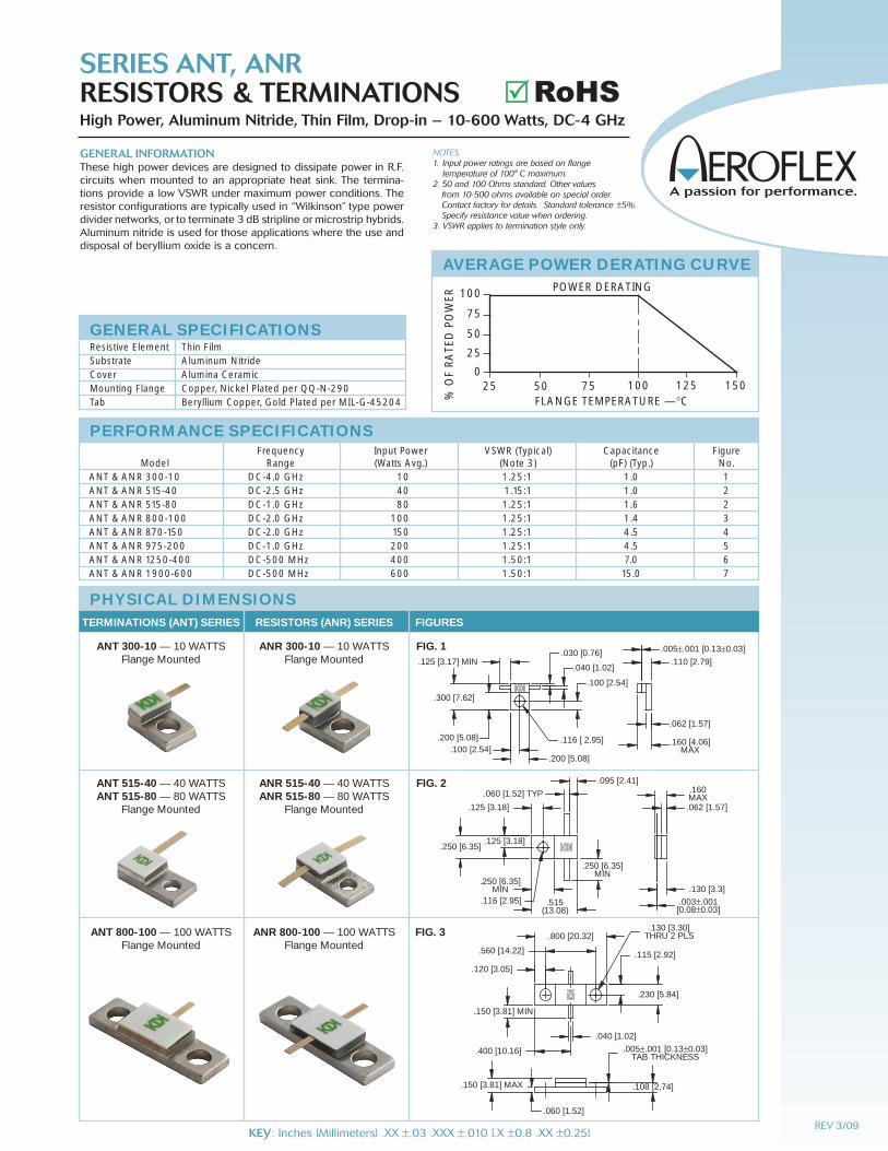
SERIES ANT, ANRRESISTORS & TERMINATIONSHigh Power, Aluminum Nitride, Thin Film, Drop-in – 10-600 Watts, DC-4 GHz
NOTES1. Input power ratings are based on flange
temperature of 100° C maximum.2. 50 and 100 Ohms standard. Other values
from 10-500 ohms available on special order. Contact factory for details. Standard tolerance ±5%. Specify resistance value when ordering.
3. VSWR applies to termination style only.
GENERAL SPECIFICATIONSResistive Element Thin FilmSubstrate Aluminum NitrideCover Alumina CeramicMounting Flange Copper, Nickel Plated per QQ-N-290Tab Beryllium Copper, Gold Plated per MIL-G-45204
AVERAGE POWER DERATING CURVE
FLANGE TEMPERATURE — °C
POWER DERATING
% O
F R
ATE
D P
OW
ER 100
100 125 150
75
75
50
50
25
250
Frequency Input Power VSWR (Typical) Capacitance Figure Model Range (Watts Avg.) (Note 3) (pF) (Typ.) No.ANT & ANR 300-10 DC-4.0 GHz 10 1.25:1 1.0 1ANT & ANR 515-40 DC-2.5 GHz 40 1.15:1 1.0 2ANT & ANR 515-80 DC-1.0 GHz 80 1.25:1 1.6 2ANT & ANR 800-100 DC-2.0 GHz 100 1.25:1 1.4 3ANT & ANR 870-150 DC-2.0 GHz 150 1.25:1 4.5 4ANT & ANR 975-200 DC-1.0 GHz 200 1.25:1 4.5 5ANT & ANR 1250-400 DC-500 MHz 400 1.50:1 7.0 6ANT & ANR 1900-600 DC-500 MHz 600 1.50:1 15.0 7
PERFORMANCE SPECIFICATIONS
.003±.001[0.08±0.03]
.130 [3.3]
.062 [1.57]
.160MAX
.250 [6.35]
.125 [3.18]
.125 [3.18]
.060 [1.52] TYP
.095 [2.41]
.250 [6.35]MIN
.515(13.08)
.250 [6.35]MIN
.116 [2.95]
PHYSICAL DIMENSIONS
ANT 300-10 — 10 WATTSFlange Mounted
ANR 300-10 — 10 WATTSFlange Mounted
ANT 515-40 — 40 WATTS ANT 515-80 — 80 WATTS
Flange Mounted
ANR 515-40 — 40 WATTS ANR 515-80 — 80 WATTS
Flange Mounted
FIG. 2
TERMINATIONS (ANT) SERIES RESISTORS (ANR) SERIES FIGURES
.062 [1.57]
.100 [2.54]
.100 [2.54]
.200 [5.08]
.300 [7.62]
.200 [5.08]
.005±.001 [0.13±0.03]
.110 [2.79].030 [0.76]
.040 [1.02].125 [3.17] MIN
.160 [4.06]MAX
.116 [ 2.95]
FIG. 1
.005±.001 [0.13±0.03]TAB THICKNESS
.040 [1.02]
.560 [14.22]
.800 [20.32]
.108 [2.74]
.060 [1.52]
.150 [3.81] MAX
.150 [3.81] MIN
.400 [10.16]
.120 [3.05]
.115 [2.92]
.230 [5.84]
.130 [3.30]THRU 2 PLSANT 800-100 — 100 WATTS
Flange MountedANR 800-100 — 100 WATTS
Flange MountedFIG. 3
REV 3/09KEY: Inches [Millimeters] .XX ±.03 .XXX ±.010 [.X ±0.8 .XX ±0.25]
RoHS��
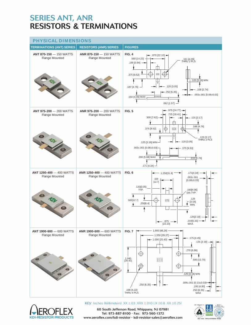
ANT 870-150 — 150 WATTSFlange Mounted
ANR 870-150 — 150 WATTSFlange Mounted
ANT 975-200 — 200 WATTSFlange Mounted
ANR 975-200 — 200 WATTSFlange Mounted
ANT 1900-600 — 600 WATTSFlange Mounted
FIG. 4
FIG. 5
FIG. 7ANR 1900-600 — 600 WATTSFlange Mounted
.125 [3.18] MIN
.250 [6.35]
1.550 [39.37]
1.000 [25.40]
1.900 [48.26]
1.040[26.42]
.175 [4.45]
.500 [12.70]
.270 [6.86]
LC
.195 [4.95]
.125 [3.18]
.166 [4.22]THRU 4 PLS
.005±.001 [0.13±0.03]
.250 [6.35]MAX
ANT 1250-400 — 400 WATTSFlange Mounted
ANR 1250-400 — 400 WATTSFlange Mounted
FIG. 6
.200 [5.08] MAX
.375 [9.53]
.110 [2.79]
.300 [7.62]
.125 [3.18] MIN
.975 [24.77]
.375 [9.52]
.725 [18.41]
.120 [3.05]
.125 [3.17]
.171 [4.34]
.125 [3.17]THRU 2 PLS
.188 [4.76]
.003±.001 [0.08±0.03]
.003±.001 [0.08±0.03]
.062 [1.57]
.155 [3.94]
.160 [4.06] MAX
.187 [4.76]
.375 [9.52]
.120 [3.05]
.250 [6.35]
.560 [14.22].870 [22.10]
.125 [3.18] MIN
.108 [2.74]
.161 [4.09]THRU 2 PLS
.500[12.7]
1.250[31.8]
.125[3.18]MIN.
500[12.7].250[6.4]
.875[22.23]
.120[3.05]TYP. .160[4.06]
DIA TYP.
.125[3.18]
.210[5.33] MAX.
.171[4.34]
.003±.001[0.08±0.03]
PHYSICAL DIMENSIONS
TERMINATIONS (ANT) SERIES RESISTORS (ANR) SERIES FIGURES
SERIES ANT, ANRRESISTORS & TERMINATIONS
KDI-RESISTOR PRODUCTS
60 South Jefferson Road, Whippany, NJ 07981Tel: 973-887-8100 • Fax: 973-560-1372
www.aeroflex.com/kdi-resistor • [email protected]
KEY: Inches [Millimeters] .XX ±.03 .XXX ±.010 [.X ±0.8 .XX ±0.25]
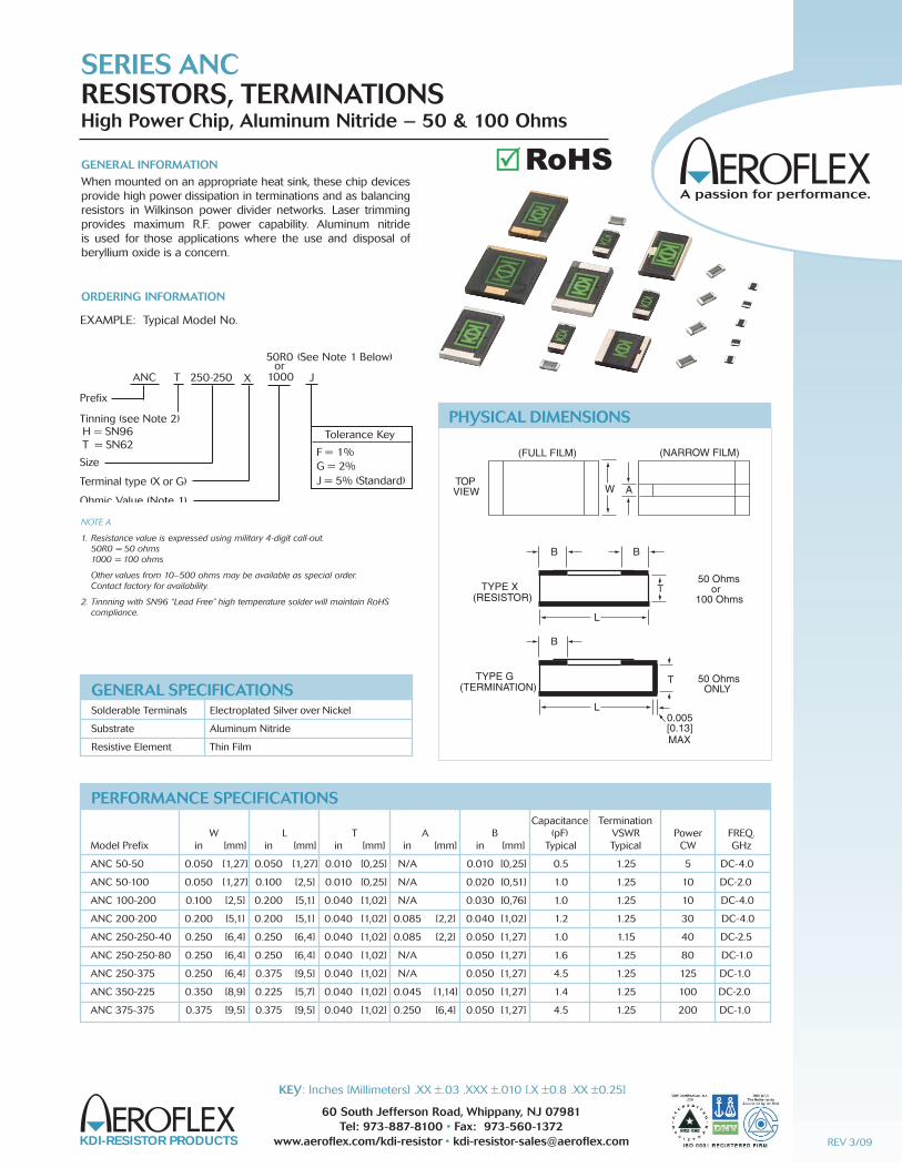
GENERAL INFORMATIONWhen mounted on an appropriate heat sink, these chip devices provide high power dissipation in terminations and as balancingresistors in Wilkinson power divider networks. Laser trimmingprovides maximum R.F. power capability. Aluminum nitride is used for those applications where the use and disposal ofberyllium oxide is a concern.
ORDERING INFORMATION
SERIES ANCRESISTORS, TERMINATIONSHigh Power Chip, Aluminum Nitride – 50 & 100 Ohms
KDI-RESISTOR PRODUCTS
60 South Jefferson Road, Whippany, NJ 07981Tel: 973-887-8100 • Fax: 973-560-1372
www.aeroflex.com/kdi-resistor • [email protected]
KEY: Inches [Millimeters] .XX ±.03 .XXX ±.010 [.X ±0.8 .XX ±0.25]
NOTE A
1. Resistance value is expressed using military 4-digit call-out.50R0 = 50 ohms1000 = 100 ohms
Other values from 10–500 ohms may be available as special order.Contact factory for availability.
2. Tinnning with SN96 “Lead Free” high temperature solder will maintain RoHScompliance.
GENERAL SPECIFICATIONSSolderable Terminals Electroplated Silver over Nickel
Substrate Aluminum Nitride
Resistive Element Thin Film
PHYSICAL DIMENSIONS
TOPVIEW W
B
T
L
B
TYPE X(RESISTOR)
T
L
B
TYPE G(TERMINATION)
50 Ohmsor
100 Ohms
50 OhmsONLY
0.005[0.13]MAX
A
(FULL FILM) (NARROW FILM)
EXAMPLE: Typical Model No.
NPC T 250-250 X J
Prefix
Tinning (see Note 2)
Size
Terminal type (X or G)
Ohmic Value (Note 1)
50R0or
1000ANC X
Tolerance Key
F = 1%G = 2%J = 5% (Standard)
(See Note 1 Below)
H = SN96T = SN62
Capacitance Termination W L T A B (pF) VSWR Power FREQ.Model Prefix in [mm] in [mm] in [mm] in [mm] in [mm] Typical Typical CW GHz
ANC 50-50 0.050 [1,27] 0.050 [1,27] 0.010 [0,25] N/A 0.010 [0,25] 0.5 1.25 5 DC-4.0
ANC 50-100 0.050 [1,27] 0.100 [2,5] 0.010 [0,25] N/A 0.020 [0,51] 1.0 1.25 10 DC-2.0
ANC 100-200 0.100 [2,5] 0.200 [5,1] 0.040 [1,02] N/A 0.030 [0,76] 1.0 1.25 10 DC-4.0
ANC 200-200 0.200 [5,1] 0.200 [5,1] 0.040 [1,02] 0.085 [2,2] 0.040 [1,02] 1.2 1.25 30 DC-4.0
ANC 250-250-40 0.250 [6,4] 0.250 [6,4] 0.040 [1,02] 0.085 [2,2] 0.050 [1,27] 1.0 1.15 40 DC-2.5
ANC 250-250-80 0.250 [6,4] 0.250 [6,4] 0.040 [1,02] N/A 0.050 [1,27] 1.6 1.25 80 DC-1.0
ANC 250-375 0.250 [6,4] 0.375 [9,5] 0.040 [1,02] N/A 0.050 [1,27] 4.5 1.25 125 DC-1.0
ANC 350-225 0.350 [8,9] 0.225 [5,7] 0.040 [1,02] 0.045 [1,14] 0.050 [1,27] 1.4 1.25 100 DC-2.0
ANC 375-375 0.375 [9,5] 0.375 [9,5] 0.040 [1,02] 0.250 [6,4] 0.050 [1,27] 4.5 1.25 200 DC-1.0
PERFORMANCE SPECIFICATIONS
REV 3/09
RoHS��
KDI-RESISTOR PRODUCTS
60 South Jefferson Road, Whippany, NJ 07981Tel: 973-887-8100 • Fax: 973-560-1372
www.aeroflex.com/kdi-resistor • [email protected]
KEY: Inches [Millimeters] .XX ±.03 .XXX ±.010 [.X ±0.8 .XX ±0.25]
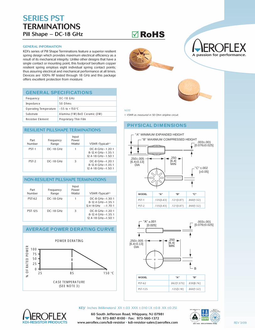
GENERAL INFORMATIONKDl’s series of Pill Shape Terminations feature a superior resiIientspring design which provides maximum electrical efficiency as aresult of its mechanical integrity. Unlike other designs that have asingle contact or mounting point, this foolproof beryllium copperresilient spring employs eight individual spring contact points;thus assuring electrical and mechanical performance at all times.Devices are 100% RF tested through 18 GHz and this packageoffers excellent protection from moisture.
SERIES PSTTERMINATIONSPill Shape – DC-18 GHz
NOTE
1. VSWR as measured in 50 Ohm stripline circuit.
PHYSICAL DIMENSIONS
MODEL "A" "B" "C"
PST-1 .135[3.43] .121[3.07] .060[1.52]
PST-2 .135[3.43] .121[3.07] .060[1.52]
MODEL "A" "B"
PST-62 .062[1.575] .030[0.76]
PST-125 .125[3.18] .060[1.52]
"C" ±.002[±0.05]
.250[6.4]MIN
.250±.005[6.4±0.13]
DIA
.250±.005[6.4±0.13]
DIA
.003±.001[0.076±0.025]
.003±.001[0.076±0.025]
"A" MINIMUM EXPANDED HEIGHT
"B" MAXIMUM COMPRESSED HEIGHT
B
"A" ±.001[0.025]
.250[6.4]MIN
AVERAGE POWER DERATING CURVE
25
100
7550
25
085 150 °C
POWER DERATING
CASE TEMPERATURE(SEE NOTE 3)
% O
F R
ATE
D P
OW
ER
Input Part Frequency Power Number Range (Watts) VSWR (Typical)(1)
PST-1 DC-18 GHz 1 DC-8 GHz—1.20:1 8-12.4 GHz—1.35:1 12.4-18 GHz—1.50:1
PST-2 DC-18 GHz 3 DC-8 GHz—1.20:1 8-12.4 GHz—1.35:1 12.4-18 GHz—1.50:1
RESILIENT PILLSHAPE TERMINATIONS
Input Part Frequency Power Number Range (Watts) VSWR (Typical)(1)
PST-62 DC-18 GHz 1 DC-8 GHz—1.30:1 8-12.4 GHz—1.35:1 12.4-18 GHz —1.70:1
PST-125 DC-18 GHz 3 DC-8 GHz—1.20:1 8-12.4 GHz—1.35:1 12.4-18 GHz—1.50:1
NON-RESILIENT PILLSHAPE TERMINATIONS
GENERAL SPECIFICATIONS
Frequency DC-18 GHz
Impedance 50 Ohms
Operating Temperature –55 to +150°C
Substrate Alumina (1W) BeO Ceramic (3W)
Resistive Element Proprietary Thin Film
REV 3/09
RoHS��
KDI-RESISTOR PRODUCTS
60 South Jefferson Road, Whippany, NJ 07981Tel: 973-887-8100 • Fax: 973-560-1372
www.aeroflex.com/kdi-resistor • [email protected]
KEY: Inches [Millimeters] .XX ±.03 .XXX ±.010 [.X ±0.8 .XX ±0.25]
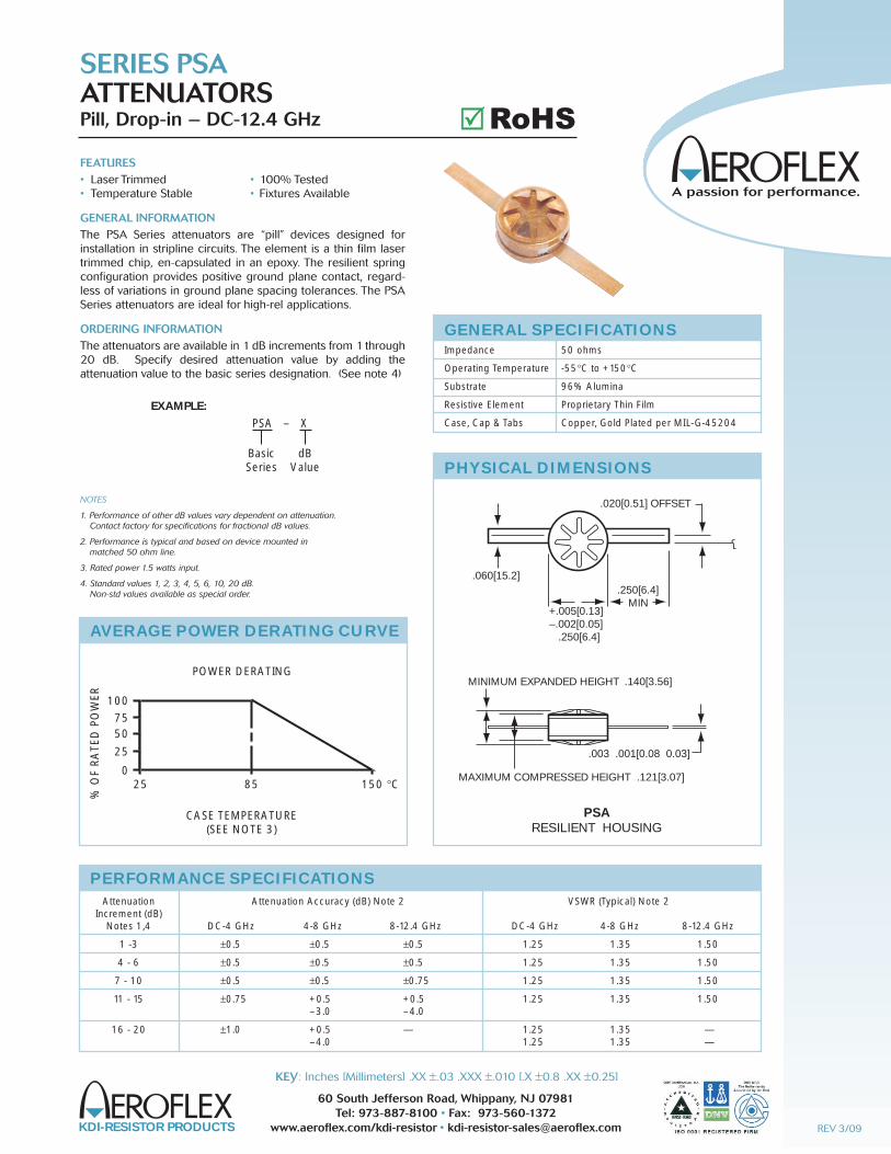
FEATURES• Laser Trimmed • 100% Tested• Temperature Stable • Fixtures Available
GENERAL INFORMATIONThe PSA Series attenuators are “pill” devices designed forinstallation in stripline circuits. The element is a thin film lasertrimmed chip, en-capsulated in an epoxy. The resilient springconfiguration provides positive ground plane contact, regard-less of variations in ground plane spacing tolerances. The PSASeries attenuators are ideal for high-rel applications.
ORDERING INFORMATIONThe attenuators are available in 1 dB increments from 1 through20 dB. Specify desired attenuation value by adding the attenuation value to the basic series designation. (See note 4)
SERIES PSAATTENUATORSPill, Drop-in – DC-12.4 GHz
NOTES
1. Performance of other dB values vary dependent on attenuation. Contact factory for specifications for fractional dB values.
2. Performance is typical and based on device mounted in matched 50 ohm line.
3. Rated power 1.5 watts input.
4. Standard values 1, 2, 3, 4, 5, 6, 10, 20 dB.Non-std values available as special order.
GENERAL SPECIFICATIONS
Impedance 50 ohms
Operating Temperature -55°C to +150°C
Substrate 96% Alumina
Resistive Element Proprietary Thin Film
Case, Cap & Tabs Copper, Gold Plated per MIL-G-45204
.020[0.51] OFFSET
.250[6.4]MIN
+.005[0.13]–.002[0.05]
.250[6.4]
.060[15.2]
MINIMUM EXPANDED HEIGHT .140[3.56]
.003 .001[0.08 0.03]
MAXIMUM COMPRESSED HEIGHT .121[3.07]
PSARESILIENT HOUSING
PHYSICAL DIMENSIONS
AVERAGE POWER DERATING CURVE
25
100
7550
25
085 150 °C
POWER DERATING
CASE TEMPERATURE(SEE NOTE 3)
% O
F R
ATE
D P
OW
ER
EXAMPLE:
PSA – X
dBValue
BasicSeries
Attenuation Attenuation Accuracy (dB) Note 2 VSWR (Typical) Note 2 Increment (dB) Notes 1,4 DC-4 GHz 4-8 GHz 8-12.4 GHz DC-4 GHz 4-8 GHz 8-12.4 GHz
1 -3 ±0.5 ±0.5 ±0.5 1.25 1.35 1.50
4 - 6 ±0.5 ±0.5 ±0.5 1.25 1.35 1.50
7 - 10 ±0.5 ±0.5 ±0.75 1.25 1.35 1.50
11 - 15 ±0.75 +0.5 +0.5 1.25 1.35 1.50 –3.0 –4.0
16 - 20 ±1.0 +0.5 — 1.25 1.35 — –4.0 1.25 1.35 —
PERFORMANCE SPECIFICATIONS
REV 3/09
RoHS��
KDI-RESISTOR PRODUCTS
60 South Jefferson Road, Whippany, NJ 07981Tel: 973-887-8100 • Fax: 973-884-0445
www.aeroflex-kdi.com • [email protected]
KEY: Inches [Millimeters] .XX ±.03 .XXX ±.010 [.X ±0.8 .XX ±0.25]
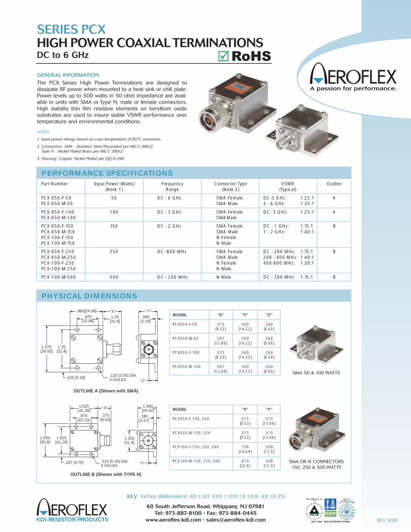
GENERAL INFORMATIONThe PCX Series High Power Terminations are designed to dissipate RF power when mounted to a heat sink or chill plate.Power levels up to 500 watts in 50 ohm impedance are avail-able in units with SMA or Type N, male or female connectors.High stability thin film resistive elements on beryllium oxidesubstrates are used to insure stable VSWR performance overtemperature and environmental conditions.
SERIES PCXHIGH POWER COAXIAL TERMINATIONSDC to 6 GHz
NOTES
1. Input power ratings based on case temperature of 85°C maximum.
2. Connectors: SMA - Stainless Steel Passivated per MIL-C-39012, Type N - Nickel Plated Brass per MIL-C-39012
3. Housing: Copper, Nickel Plated per QQ-N-290
PHYSICAL DIMENSIONS
1.375[34.93]
.120 [3.05] DIA.4 HOLES.125 [3.18]
.960[24.38].625
[15.88]
"X"1.25[31.8]
"Y".090[2.29]
"Z"
1.25[31.8]
1.625[41.28]
2.000[50.8]
1.250[31.8]
.215 [5.46] DIA.4 HOLES
.187 [4.75]
1.625[41.28].875
[22.23]
"X"
.375[9.53]
1.060[26.92]
.180[4.57]
"Y"
OUTLINE A (Shown with SMA)
OUTLINE B (Shown with TYPE N)
MODEL "X" "Y" "Z"
PCX050-F-50 .375 .560 .260 [9.53] [14.22] [6.60]
PCX050-M-50 .507 .560 .260 [12.88] [14.22] [6.60]
PCX050-F-100 .375 .560 .260 [9.53] [14.22] [6.60]
PCX050-M-100 .507 .560 .260 [12.88] [14.22] [6.60]
MODEL "X" "Y"
PCX050-F-150, 250 .375 .515 [9.53] [13.08]
PCX050-M-150, 250 .375 .515 [9.53] [13.08]
PCX100-F-150, 250, 500 .736 .508 [18.69] [12.9]
PCX100-M-150, 250, 500 .819 .508 [20.8] [12.9]
Part Number Input Power (Watts) Frequency Connector Type VSWR Outline (Note 1) Range (Note 2) (Typical)
PCX-050-F-50 50 DC - 6 GHz SMA Female DC-3 GHz: 1.25:1 A PCX-050-M-50 SMA Male 3 - 6 GHz: 1.35:1
PCX-050-F-100 100 DC - 3 GHz SMA Female DC- 3 GHz: 1.25:1 A PCX-050-M-100 SMAMale
PCX-050-F-150 150 DC - 2 GHz SMA Female DC - 1 GHz: 1.15:1 B PCX-050-M-150 SMA Male 1 - 2 GHz: 1.40:1 PCX-100-F-150 N Female PCX-100-M-150 N Male
PCX-050-F-250 250 DC -800 MHz SMA Female DC - 200 MHz: 1.15:1 B PCX-050-M-250 SMA Male 200 - 400 MHz: 1.40:1 PCX-100-F-250 N Female 400-800 MHz: 1.30:1 PCX-100-M-250 N Male
PCX-100-M-500 500 DC - 200 MHz N Male DC - 200 MHz: 1.15:1 B
PERFORMANCE SPECIFICATIONS
SMA 50 & 100 WATTS
SMA OR N CONNECTORS150, 250 & 500 WATTS
REV 3/09
RoHS��