Embed Size (px)
Citation preview

AEROELASTIC RESPONSE OF NONLINEAR WING
SECTION BY FUNCTIONAL SERIES TECHNIQUE
PIERGIOVANNI MARZOCCA*, LIVIU LIBRESCU**
and
WALTER A. SILVA *
* Engineering Science and Mechanics Department, Virginia Polytechnic Institute and State
University, Blacksburg, VA 24061-0219, USA.
and
NASA Langley Research Center, Hampton, VA 23681-2199, USA.
Office:
Fax:
t Corresponding author
(540) 231 - 5916 Home: (540) 953 - 0499
(540) 231 - 4574 Email: [email protected]

AEROELASTIC RESPONSE OF NONLINEAR WING
SECTION BY FUNCTIONAL SERIES TECHNIQUE
Piergiovanni Marzocca* and Liviu Librescu***Virginia Polytechnic Institute and State University, Blacksburg, VA 24061-0219,
Walter A. Silva*
*NASA Langley Research Center, Hampton, VA 23681-2199.
Abstract
This paper addresses the problem of the determination of the subcritical aeroelastic
response and flutter instability of nonlinear two-dimensional lifting surfaces in an
incompressible flow-field via indiciai functions and Volterra series approach. The related
aeroelastic governing equations are based upon the inclusion of structural and damping
nonlinearities in plunging and pitching, of the linear unsteady aerodynamics and
consideration of an arbitrary time-dependent external pressure pulse. Unsteady aeroelastic
nonlinear kernels are determined, and based on these, frequency and time histories of the
subcriticai aeroelastic response are obtained, and in this context the influence of the
considered nonlinearities is emphasized. Conclusions and results displaying the implications
of the considered effects are supplied.

Nomenclature
a Dimensionless elastic axis position measured from the mid-chord, positive aft
c Chord length of 2-D lifting surface, 2b
Ch_,C_, Kh_, K_ Damping and stiffness coefficients in plunging and pitching (i=1,2.3 - linear,
quadratic, cubic), respectively
CL,_ Lift-curve slope
C(k _ F(k), G(k) Theodorsen's function and its real and imaginary counterparts, respectively
h,_ Plunging displacement and its dimensionless counterpart, (h/b), respectively
h, H. n-th order Volterra kernel in time, and its Laplace transformed counterpart, respectively
I,_, r_ Mass moment of inertia per unit wingspan and the dimensionless radius of gyration,
(I s/mb 21/2 , respectively
la,m _ Dimensionless aerodynamic lift and moment, (L,b/mU2)and (Mb'/I_U_),
respectively
L, M. Total lift and moment per unit span
Lb, lb Overpressure signature of the N-wave shock pulse and its dimensionless counterpart,
(Lbb/mU _ ), respectively
m,/1 Airfoil mass per unit length and reduced mass ratio, (rn/rcpb 2 ), respectively
N Load factor, 1 + h'/g
, p 2Pm _o Peak reflected pressure amplitude and its dimensionless counterpart, ( mb/mU_ ),
respectively
r Shock pulse length factor
s j, _' Laplace transform variable and Laplace operator, respectively, sj = ikj;i2 = -1
S,_, Z_ Static unbalance about the elastic axis and its dimensionless counterpart, S_ �rob,
respectively
t, %, z Time variables and dimensionless counterpart, (U.t/b), respectively
tp,z e Positive phase duration, measured from the time of the arrival of the pulse, and its
dimensionless value, respectively

TF Transfer function
Uoo, V Freestream speed and its dimensionless counterpart, (U=/bco_ )
x(t) Time-dependent external pulse (traveling gusts and wake blast waves)
y(t) Response of the considered degree of freedom (pitch o_and/or plunge h)
a Twist angle about the pitch axis
(h, _',_ Structural damping ratios in plunging (ch/2mco,,), and pitching (c,_/2I,_o9,_),
respectively
p Air density
_('t') Wagner's indicial function
to, k Circular and reduced frequencies, (a_b / U= ), respectively
cob,co _ Uncoupled frequencies in plunging and pitching, (Kh/m) _'2 and (K_/I_)1/2,
respectively
Plunging-pitching frequency ratio, (coh/co d )
Superscript
^
( ) Variables in Laplace transformed space
( • ), ( • ) Derivatives with respect to the time t, and the dimensionless time z, respectively

I. Introduction
It is a well-known fact that within the linearized approach of the aeroelasticity discipline, it is
possible to obtain the divergence and the flutter instability boundaries, and also to get the
linearized subcritical aeroelastic response to time-dependent external pulses, such as blast and
sonic boom pressure signatures and gust loads. On the other hand, the nonlinear approach of the
aeroelastic problem can provide important information: i) on the influence of the considered
nonlinearities on the subcritical aeroelastic response, and ii) about the character of the instability
flutter boundary, i.e. benign or catastrophic one. In other words, such an approach gives the
possibility of determining in what conditions the flutter speed can be exceeded without the
occurrence of a catastrophic failure of the wing, in which case the flutter is benign, as well as the
conditions in which undamped oscillations may appear at velocities below the flutter velocity, in
which case the flutter is catastrophic. In addition, the considered nonlinearities play a great role
on the subcritical aeroelastic response of lifting surfaces. Due to the strong implications of
various nonlinearities on the highly flexible lifting surfaces, their related aeroelastic phenomena
cannot longer be analyzed only within the standard linearized aeroelasticity theory. Aircraft wing
structures often contain nonlinearities, which affect their aeroelastic behavior and performance
characteristics, and flutter boundaries. For these reasons, in order to investigate the aeroelastic
behavior of lifting surfaces in the vicinity of the flutter boundary, the aeroelastic governing
equations have to be necessarily considered in nonlinear form.
This investigation concerns the aeroelastic response of two-dimensional nonlinear lifting
surfaces exposed to an incompressible flow field and subjected to an external pressure pulse I-3.
Based on Volterra's functional series approach 4-8 pertinent information about the effects of
nonlinearities on either the aeroelastic response in the subcritical flight speed regime, and their
implication on the flutter boundary are supplied.
The advantage of the technique based on Volterra's series and indicial function (Lomax 9,
Bisplinghoff 1°, Marzocca et al. 11) consists, among others, on the possibility to investigate, within
a rigorous theoretical basis, the aeroelastic systems featuring a wide class of nonlinearities. As a
limiting case, based upon the first order Volterra kernel the study of the linear aeroelastic
stability of the systems can be carried out. This methodology can encompass the case of an
arbitrary number of degrees of freedom and at the same time is conceptually clearer,
computationally simpler and can provide more accurate and realistic results as compared to the

conventional techniques used in nonlinear aeroelastic systems based on perturbation and multiple
scale methods. In addition, this method, as shown in this paper, features a faster convergence as
compared to the other methodologies. Moreover, this method does not experience the limitations,
usually characterizing the other techniques, such as the Hilbert transform t2J3, developed to
identify nonlinear systems from the first order frequency response function (FRF), or the phase
plane methods that can describe the motion as just a function of two variables. In contrast to
these methods that are suitable mainly to one degrees of freedom systems, Volterra series
approach overcomes the shortcomings facing the other methods, consisting of the impossibility
to cope with exchange of energy between the different mode frequencies.
Toward the end of determining the nonlinear unsteady aeroelastic kernels, the harmonic probing
algorithm, referred to as the method of growing exponentials advanced by Bedrosian and
Rice 14'15, and the multidimensional Laplace transform 16will be used.
In addition to the aeroelastic response and determination of the flutter instability boundary,
Volterra Series considered in conjunction with this nonlinear aeroelastic model can be used to
study the conditions rendering the flutter boundary a benign or a catastrophic one (Librescu17'ls).
Moreover, when the closed-loop dynamic response of actively controlled lifting surface is
analyzed, also the feedback control forces and moments should be included (Librescu 17'18, Gem
and Librescu 19, Librescu and Na 2°, Van Trees 21, Chua and Ng 22) and Volterra's series approach
can still be applied towards the control purpose.
Volterra's series approach provides a firm basis for the treatment of the nonlinear subcritical
aeroelastic response, in the sense that it supplies an explicit relationship between the input (any
type of time-dependent external pulses, i.e. blast load, sonic-boom, gust loads) and its response.
With the so-called Volterra Kernel identification scheme, the modeling of an aeroelastic system
using this approach becomes feasible. However, this methodology requires determination for
each specific flight conditions of the corresponding nonlinear kernel of the Volterra's series. For
this reason, in order to define the appropriate aerodynamic loads, the recent interest in the
modeling of unsteady nonlinear aerodynamics by this approach has been focused on the
identification of Volterra's kernels in the time domain (Silva2326), and in the frequency domain
(Tromp and Jenkins27).

A number of fundamental contributions related to Volterra's series, developed by outstanding
mathematicians (Volterra 4, Wiener s) and used mainly in electrical engineering 6-8, are already
available.
The original studies on functional series by Volterra 4, have been continued in the works by
Volterra himself, and of those by Rugh 6, Schetzen 7, Boyd 8. These concepts have been mainly
used in the general nonlinear system theory.
Originally, the method of Volterra series and Volterra kernel identification were developed to
identify the nonlinear behavior in electrical circuits. In the aerospace field, the fundamental
contributions were brought by Silva 23, who has shown that the method is also applicable to
aeroelastic systems (aerodynamic reactions and forced structural model). Silva's pioneering
work 23-26 in this area has opened a very promising way of modeling and approaching nonlinear
aeroelastic systems.
II. Basic Concepts
Having in view that for nonlinear systems the superposition principle is not applicable, and
having in view the different types of responses induced by unsteady aerodynamic loads and
external excitation, a combination of transfer functions is used. For the nonlinear aeroelastic
systems these transfer functions and the time-histories response in time and frequency domains
are determined by taking the multi-dimensional Laplace transform of Volterra kernels of the
related aeroelastic system via a Mathematica ® code developed by these authors _8. Our approach
intended to address the subcritical response of the nonlinear aeroelastic governing equations, is
based on its exact representation as an infinite sum of multidimensional convolution integrals,
the first one, (i.e. the linear kernel) being the analogous to the linear indicial aeroelastic function.
The full nonlinear aeroelastic response will be composed of additional higher-order
contributions. In the frequency domain, if the nonlinear function governing a system is
"smooth", then for small inputs the system must be asymptotically linear 6. One of the key issues
is to determine, corresponding to the considered type of structural, damping and aerodynamic
nonlinearities, the pertinent Volterra's kernels. When also the active control is implemented, the
corresponding Volterra's kernel should also be determined.

III. The Theory
In an attempt to make the paper reasonably self-contained, several elements associated with the
indicial functions and Volterra's series as applied to aeroelastic system, will be supplied here.
A. Indicial Theory and Aerodynamic Loads
Using the aerodynamic indicialfunctions corresponding to the transient aerodynamic reaction
to a step pulse, the aerodynamic forces and moments induced in any maneuver and flight regime
can be determined. Aerodynamic forces and moments acting on a rapidly maneuvering aircraft
are, in general, nonlinear functions of the motion variables, their time rate of change, and the
history of the maneuvering (Tobak and Chapman29). However, in this study, the linear
aerodynamic theory is adopted. Once the response of the system to a step change in one of the
disturbing variables (i.e. the indicial response) is known, the indicial method permits
determination of the response to an arbitrary schedule of disturbances. There is a critical value of
the flight speed, referred to as the flutter speed, above which the steady motion becomes
unstable. In a nonlinear aeroelastic system the flutter phenomenon corresponds to the instability
known as the Hopf bifurcation, resulting in the case of supercritical Hopf bifurcation in finite
amplitude oscillations, and in the case of the subcritical Hopf bifurcation in oscillations with
increasing amplitudes, even if the system operates before reaching the flutter speed 3°-32.
We need to mention that within the nonlinear indicial theory 33, the response of a nonlinear
system to an arbitrary input can be constructed by integrating a nonlinear functional that involves
the knowledge of the time-dependent input and the kernel response. Whereas, within the linear
indicial theory the linear kernel or linear impulse response can be convoluted with the input to
predict the output of a linear system, the nonlinear indicial theory constitutes a generalization of
this concept. It can also be shown that the traditional Volterra-Wiener theory of nonlinear
systems constitutes a subset of the nonlinear indicial theory. It should also be mentioned that the
nonlinear unsteady aerodynamics valid throughout the subsonic incompressible/compressible,
transonic and supersonic flight speed regimes can be used and determined via the use of
nonlinear indicial functions in conjunction with the Volterra's series approach.
B. Volterra Functional Series Theory
As it was shown (Rugh 6, SchetzenT), within Volterra's series approach the full response in the
time domain, y(t), of the nonlinear systems with memory can be cast as:

where, Yk (t) is expressed as:
y(t)=_yk(t ), (1)k--O
k
Yk(t) = fff__hk(t--Tl,t--'_'2,'"t--_k)l-Ix("l_i)q_'i • (2)
k times i=1
By a change of variables, it is possible to express Eq. (2) in contracted form as:
k
y,. (t) = IfIffhk(Vl,V2,...L)l--IxO-T,):lr,. (3)k times i=1
It is assumed that x(t)= 0 for T < 0, implying that the system is causal.
With this restriction, all the integrals in the subsequent discussions are different from zero over
the time range [0,oo). Restricting the development of Eq. (3) to the first three terms one obtains:
y(t )= f h, (v, )x(t - r_ )dr, + If h2 (Ti , T2 )x(t - T1)x(t - Te )dTldg2
+ IIIh3('c,,v2,'c3)x(t-'cl)x(t-'r2)x(t-'c3)d'cld'g'2dv3 +"" (4)
On the other hand, the response of the system can be expressed also in the frequency domain.
Volterra' series is essentially a polynomial approximation of the system, extension of Taylor
series to systems with memory, while Volterra's kernels hi(si) are a direct extension of the
impulse response concept of the linear system theory to multiple dimensions (Volterra s, Rugh 6,
Schetzen 7, Boyd8). Consequently, a multidimensional analogue of the impulse response can be
used to characterize a nonlinear system (Silva23-26).
Having in view that the memory of aeroelastic systems is not infinite and, at the same time, the
time-dependent external excitations, such as impulse, gust, blast and sonic-boom pressure
signatures are non persistent, (in the sense that their effect decay as time unfolds), it is possible
to characterize a nonlinear aeroelastic system via Volterra series. This fact is reflected in the
interpretation of the Volterra kernels as higher order impulse response functions, i.e.
h(r,,...,v° )--+ 0 as r,,...,v, + oo.
We will use the definition of the nonlinear transfer function or higher-order impulse response
functions namely:
Hn(sI,s2,'"sn) = ff...Ih,(vi,v2,'",L )e-S'r'e-S=_="'e-'"_"d'Cld'C2...d'c,, (5)
as well as of their inverted counterparts:

.....Once Volterra's kernels are known, the response of the nonlinear aeroelastic system can fully be
identified. As demonstrated in the Schetzen works v, without loss of generality, the kernels will
be taken as symmetric, in the sense of H,(sl,s 2.... )= H,(sa,S l .... ), and a similar relationship
being valid for h,, as well.
If we focalize the attention on the linear system, the Laplace transform _ of the first term of Eq.
(4) yields the familiar Laplace domain expression Y(s)= H(s)X(s), where Y(s_H(s_X(s) are
the Laplace transforms of y(z _ h(r), x(z), respectively. H (s) is the transfer function TF of the
system. It is well known fact that for the linear system, either the first transfer function or the
first kernel in time h(T) encode all the information about the aeroelastic system. Moreover, as is
well known, if the system is linear, i.e. superposition principle holds valid and is time invariant,
the external load is uniquely related to the response by a convolution integral. With the use of
functional series, i.e. the Volterra series, this functional representation can be extended to
nonlinear systems. The comparison between the prediction of the linear aeroelastic responses of
2-D lifting surface in incompressible flow field based on the Volterra's series approach (using
Theodorsen's function C(k)) and on the exact solution, based on convolution integrals (using
Wagner's function ¢(r)) is presented in Fig. 1.
The excellent agreement of these two predictions, assess both the accuracy of the aeroelastic
model and also the power of the methodology that combines Volterra's series and the indicial
function.
IV. Mathematical Formulation
A. General Theory for Wing Sections Including Structural and Damping
Nonlinearities in Plunging and Pitching
The aeroelastic governing equation of motion for 1- and 2-DOF lifting surfaces featuring
structural and damping nonlinearities, that include the stiffnesses and the damping in plunging
and pitching, will be analyzed next. In this sense: a 1-DOF lifting surface featuring purely
plunging motion and a 2-DOF lifting surface featuring inertial and aerodynamic coupling in
plunging h and pitching _ will be analyzed. As previously mentioned, the unsteady aerodynamic

is considered linear. A harmonic time dependent external concentrated load is also included in
the analysis. This can be considered to correspond, for example, to an engine mounted on an
aircraft wing. As a result, a harmonic type loading due to the engine oscillations has to involve
the motion of the wing.
As a characteristic of this approach, the transfer functions of the system would exist and would
be the same for any excitations 34-36, such as impulse, gusts, airblast or sonic-booms (random or
deterministic ones). This is due to the fact that transfer functions are independent of the input to
the system, being a characteristic of the system itself. As a reminder, the validity of this method
is based on the use of continuous polynomial type nonlinearities. For nonlinear ordinary
differential systems, there are in general, an infinite number of Volterra kernels. In practice, one
can handle only a finite number of terms in the series, which leads to the problem of truncation
accuracy. However, Wiener 5 suggest that the first terms of the series may be sufficient to
represent the output of a nonlinear system if the nonlinearities are not too strong.
The use of the multidimensional Laplace transform as a function of several variables is a tool
useful in stationary nonlinear system theory. The multivariable convolutions can be represented
in terms of products of Laplace transforms.
It is well known that the nonlinear aeroelastic systems cannot be described by a simple transfer
function for two main reasons: a) the response encode both the unsteady aerodynamic loads and
the external excitation effects, and b), in the nonlinear case the superposition principle is not
applicable. It is also well known that any time-dependent external excitation, i.e. periodic or
otherwise, can be represented, to an arbitrary degree of accuracy, by a sum of sinusoidal waves 34.
In this context, if the external load is expressed in terms of multiple sinusoidal forms (for
example, a traveling gust loads) this is easily convertible in the exponential form, i.e.:
u(t)= Acos(coat)+ Bcos(o)J)e=_u(t)= A(e'"' +e -_w)+ B (e'"' +e -_'"' ), (7)
where s A = i09 A and s s = io) e . For clarity of exposition, it is convenient to adopt this approach
for a system with one degree of freedom (1-DOF). These results have more general bearing and
can be extended for systems with multi-degrees of freedom (M-DOF). In fact, by using the
classical approach of the one dimensional frequency response function, it is possible to derive an
analytical form of the multi-dimensional frequency response characteristics of nonlinear systems.
!0

The systemsbasedon 1-DOF (plunging h) and 2-DOF (pitching a and plunging h), will be
considered in the next sections.
B. Plunging Airfoil Motion in an Incompressible Flow Field
The nonlinear equation of an airfoil featuring plunging motion can be expressed as:
i=l
where i defines the degree of the considered nonlinearity. In the numerical simulations, i will
assume the values 1,2,3, implying linear, quadratic and cubic nonlinearities. In addition, m is
mass parameter and Chi, khi, are the damping and stiffness parameters, respectively, that are
associated to the damping and deflection in plunging corresponding to the i-th power. In the right
hand side member of these equations, L_ (v) denotes the external time-dependent load acting on
the rigid wing counterpart. In Eq. (8) the related unsteady aerodynamic lift is represented as a
function of the plunging degree of freedom h, only:
L,, (Z)=--CL_pU _ f__ (J('C--'C o )h'dz o -½ PCL_U 2 h'. (9)
The non-circulatory component present in Eq. (9) has been represented in term of convolution
integral of the indicial Wagner's function.
In order to explain how this methodology works, let us to determine, in terms of Volterra series,
how a system responds to a harmonic or periodic time-dependent load. Let consider a periodic
external excitation in the form:
Lb(t):_.Xje 'j' . (10)j=l
As is well known, the information acquired by the case of the response to a harmonically time-
dependent load can be used to obtain the response to any time-dependent external excitation. In
fact, considering the case of a concentrated load arbitrarily located in the x, y plane of the wing,
we have:
u(x, y,t)= At_(X-Xo,Y- y0)# u , (11)
where fi(.), xo, yo, A, co denote Dirac's distribution, location of the load, its amplitude and
excitation frequency, respectively. Once determined the transfer function (labeled as TF)
II

corresponding to a given excitation frequency, its counterpart in the time domain can be obtained
as the inverse Laplace transform o_-_:
rF(x, y,t)= Z-'{rF(x, y,s)}= rF(x, y,s)e"ds. (12)
In addition to the direct role in the determining of the response, the transfer function TF has then
the role in determining the response to arbitrary time-dependent external excitations.
The general procedure to identify the aeroelastic kernels of various order 1,(_n), is to consider a
general input in the form of Eq. (10) and to equate, for the generic term of n order, the
coefficients of X_X 2...X,,e (''+':++")'. As an example, the first aeroelastic Volterra's kernels
that describes the linear system, obtained by neglecting the nonlinear terms in the aeroelastic
governing equations, is obtained by considering the input load as Lb(t)=X_e 'v (which in
dimensionless form is expressed as Ih(t)=(b/mU_)X,e'v); the response of the system is
postulated in the form h(t)=H,(s,)X,e'" +h.o.t. Substituting h(t) and its derivatives in the
governing equation of motion, one determines the coefficient of X_e'".
In a linear aeroelastic formulation, the system is completely characterized by a transfer function
H_ (s_) that contains the aerodynamic term as follow:
H,(s,)=(kh, +ms, 2 +Ch,S , + s, PCL_bV=C[-is,b/U.]+'_PCL_s,2b2_ ' . (13)
Herein the Theodorsen's function C, connected with the Wagner's indicial function ¢(T) via the
Laplace's transform as C(-is)= s_ O(r)e-S¢dr, has been included in the formulation. The terms
underscored by the solid line correspond to the unsteady aerodynamic loads component
(circulatory term), while the dotted line corresponds to the effect of the added mass. When the
aerodynamic loads are neglected and for s = ira, this result coincides with that of the linear FRF,
derived via the conventional Modal Analysis. Notice that, the condition s = io) correspond to
zero initial conditions; the effect of the initial condition on the nonlinear aeroelastic response can
be included remembering the complete form of the complex variable s, in which also the real
part of the variable is included, namely, s = cr + ira.
For purely mechanical systems, in the frequency domain, the response via Volterra series has
been carried out by several authors. In the present study an alternative procedure, based on the
12
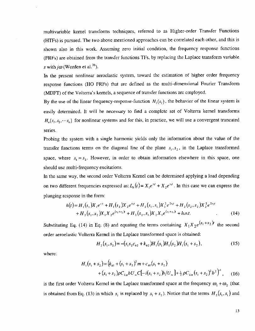
multivariable kernel transformstechniques,referred to as Higher-orderTransfer Functions
(HTFs) is pursued.Thetwo abovementionedapproachescanbecorrelatedeachother,andthis is
shown also in this work. Assumingzero initial condition, the frequencyresponsefunctions
(FRFs)areobtainedfrom thetransferfunctionsTFs,by replacingtheLaplacetransformvariable
s withjfo (Worden et al.36).
In the present nonlinear aeroelastic system, toward the estimation of higher order frequency
response functions (HO FRFs) that are defined as the multi-dimensional Fourier Transform
(MDFT) of the Volterra's kernels, a sequence of transfer functions are employed.
By the use of the linear frequency-response-function H/(s/), the behavior of the linear system is
easily determined. It will be necessary to find a complete set of Volterra kernel transforms
H,(sl,s2,...s,,) for nonlinear systems and for this, in practice, we will use a convergent truncated
series.
Probing the system with a single harmonic yields only the information about the value of the
transfer functions terms on the diagonal line of the plane s_,s 2, in the Laplace transformed
space, where s I = s z . However, in order to obtain information elsewhere in this space, one
should use multi-frequency excitations.
In the same way, the second order Volterra Kernel can be determined applying a load depending
on two different frequencies expressed as: Lh (t) = XI es't + X2e _'-'. In this case we can express the
plunging response in the form:
h(t)=H,(sl)Xle 'v +HI(s2)X2 es2t +H2(s'l,sl)X?e z'_' +H2(s2,sz)XZe 2s2'
+ Hz(s,,sz)X,Xze (_''+_'-_+ Hz(sz,s,)XzX,e ('2+''_ +h.o.t. (14)
Substituting Eq. (14) in Eq. (8) and equating the terms containing XIX2 e(sl +sz)t the second
order aeroelastic Volterra Kernel in the Laplace transformed space is obtained:
H2(st,sz):-(s_szch2 +khz)Hl(s_)H,(sz)H,(s , + s2), (15)
where:
HI(SI +Sa)=(khl +(SI +S2)2m+ch,(SI +S,)
+(s, +sz)pCL_bU=C[-i(s, q-s2)b/U.]-[-lpfLa(S, "l-$2)262) -1 ' (16)
is the first order Volterra Kernel in the Laplace transformed space at the frequency _oi + a)2 (that
is obtained from Eq. (13) in which s_ is replaced by s_ + s:). Notice that the terms H2(st,s _) and
13

H2($2,$2) can be determined from Eq. (15) replacing s2 with s_ and vice versa, respectively.
Following the same steps, applying the load Lb(t)= X_e s't + X2e'"' + X3 es:'' , equating the terms
-_T '_r 'it (sl+s2+s3)tin the form AIAZA3e and remembering that:
H,(s, +s 2 +s3)=(k 1 +(st +s 2 +s3)2m+q(s, +s 2 +s3)
I 2+(s,+s2+s3)PCL_bU=C[-i(s,+s2+s3)b/U=]+TP b CLa(SIq-S2q-S3)2_ 1 , (17)
the expressions for the third order Volterra Kernel in the Laplace transformed space results:
H3 (sI .s2.s3 )-- -2 (HI (s3 XNHI (sI )HI (s2 Xkh3 -{-Ch3SlS2S3 )
+ 2H2(Sl,s2Xkh2 +ch2(Sl + s2)$3))+ 2(HI(s2)H2(s3,SlXkh2 +Ch2S2(Sl + S3))
-H,(s2)H2(s2,s3Xkh2 +ch2st(s2 +s,))))/(nl(sl +$2 + s3)) .(18)
Notice that the constants kh2 and ch: multiply the whole expression of H 2, and this term
vanishes if the quadratic nonlinear term is absent in the aeroelastic governing equations. Herein
one of the general properties of Volterra's series is recalled, namely that if all nonlinear terms in
the equation of motion for the system consist of odd powers of x and y, then the associated
Volterra series have no even-order kernels, and as a result it will possess no even-order TFs. It is
also a general property of systems that all higher-order TFs can be expressed in terms of H_.
The expressions are function of the system and can be obtained by using the harmonic probing
algorithm. It clearly appears that the higher order of FRFs, defined from the Volterra series, are
independent of the input to the system.
C. Plunging-Pitching Airfoil Motion in an Incompressible Flow Field
The governing aeroelastic system of an airfoil featuring plunging - twisting coupled motion,
exposed to a harmonic time dependent external excitation is:
n
•' 2(c 'm]_+S_o_+ hjh +khjh -L. =L b, (19)i=1
-. " • i i )_ M. = 0. (20)S.]_ + I,_a + Z (co_a + k_ai=1
Considering, as usual, the blast load Lb (r) as uniformly distributed in the chordwise direction, no
moment contribution M b (v) is introduced in Eq. (20).
14

Following the steps adopted for 1-DOF, applying a load depending on one frequency Lh = Xle'",
and expressing the plunging and pitching displacements in terms of transfer functions as:
..2,,,,, )e2,,, 3 ,, )e3,,, (21)h(/)= XIH['(sI)e sit + a I 112 _si,s I nt- X t H 3 (si,s,,s 1 ,
= _ _ Xi'H_(s,,s ' s,)e 3''' (22)a(t) XIH_(sI)e s't + XI'H 2 (si,si)e 2s't .-I- , ,
the relative kernels and the aeroelastic responses can be determined.
The aeroelastic governing system including the blast pressure signatures can be expressed in the
Laplace transformed space as:
s=4+Z"S2d+2¢h_ ^ sa + s=_ + s "2 I.l--_-s{ + + -a (s)+ s2(4-aa)+lsd_=l,,(s), (23/
(Za/rZ_)s2'+sZ&+'2'a/V)s&+dt/V2 -(l+a']24(s_+s2_+s2( 1_2 ) tt ra _, _-a ?)t_(s)
, as2(4-aa)+ -a 2- ---r- =0. (24)r[, It )r2 it 8r, It
Herein (.")= a_(.), and consequently _ =:e(_(t)) and a = _(a(t)).
Following the same steps, applying the loads L h (t)= X_e ''t + X2 es2t and
Lh(t)= Xle s't + X2 es2' + X3 es_', equating the terms in the forms X_X2 e(_'÷':)' and
XjXzX3e (s_+s2÷s3)t, the expressions for the second and third order Volterra Kernel in the Laplace
transformed space can be obtained.
D. Generalization to Multi Degrees of Freedoms Systems (M-DOFs)
The method shown for 1-DOF and 2-DOF lifting surfaces can be extended to systems featuring
multi degrees of freedoms in general, and to a 3-D aircraft wing in particular. The method of
deriving the n-th order nonlinear aeroelastic transfer functions is based upon the fact that when
the aeroelastic system described by the response y(t) (expressed via Volterra series), is excited
by a set of k unit amplitude exponentials at the arbitrary frequencies s/, s2 ..... &, the output will
contain exponential components of the form:
y(t)= ,,_l _ n' )_3(mlsl+m2s2+...+mnsn} tm 1!m2 !...m, !H, (s,, s 2,..-s. . (25)
15

The presenceof nonlinearitiescausesharmonicexcitationsandsumsof harmonicsto appearin
the responseof the aeroelasticsystem.Due to the nonlinearformulation,different frequencies
canbeexpectedaswell.
Fromtheenergeticpoint of view, wecanobservethat H_ (s_) produces a single frequency output
in response to the simple input e _'' . However, because the system is nonlinear, H 2 (sl, s 2 ) takes
into account the terms that produce an output energy corresponding to the sum of frequencies
ml + 092 , or in other words to the input e (_'+s2)'. Similarly, the third order nonlinear aeroelastic
kernel, will inject a mix of three input frequencies into the total system output (see Figs. 6-8).
This is the great advantage of this methodology over the other approaches based on the first
order frequency response function. In contrast to these methodologies Volterra's series approach
is able to capture the transfer of energy between frequencies, that is typical for nonlinear
systems.
V. Results and Discussion
To assess the versatility and provide a validation of this methodology, a comparison of the
predictions of the aeroelastic response of nonlinear 2-D lifting surface using three
approximations are shown in Figs. 2 and 3. The excellent agreement of the predictions, assess
both the accuracy of the aeroelastic model and also the power of the methodology based on the
Volterra series and indicial function approach. The first, the second and the third approximations
of the aeroelastic response to the two loads 1-COSINE gust load and triangular blast load are
plotted for different parameters, together with the "exact" response of the aeroelastic system as
obtained through digital-computer solution of the nonlinear aeroelastic governing equations.
Both figures reveal the rapid convergence of the approximation. The same approach has been
applied to a nonlinear time-varying system represented in Ref. 37 in which a transient response
analysis of a continuous system has been addressed via functional techniques and
multidimensional Laplace transformation. The impulse response of the system, represented by
the differential equation:
dc(t) l- ac(t)+km(t)c(t)+e c2(t) = R 6(t), (26)dt
evaluated with the present analysis coincides with that shown in the Ref. 37 in which the
parameters in use are:a=l,R=l,k=l, lO, e=l,m(t)=sin(COot),mo=ZZc,2Orc. Figs. 4 and 5
16
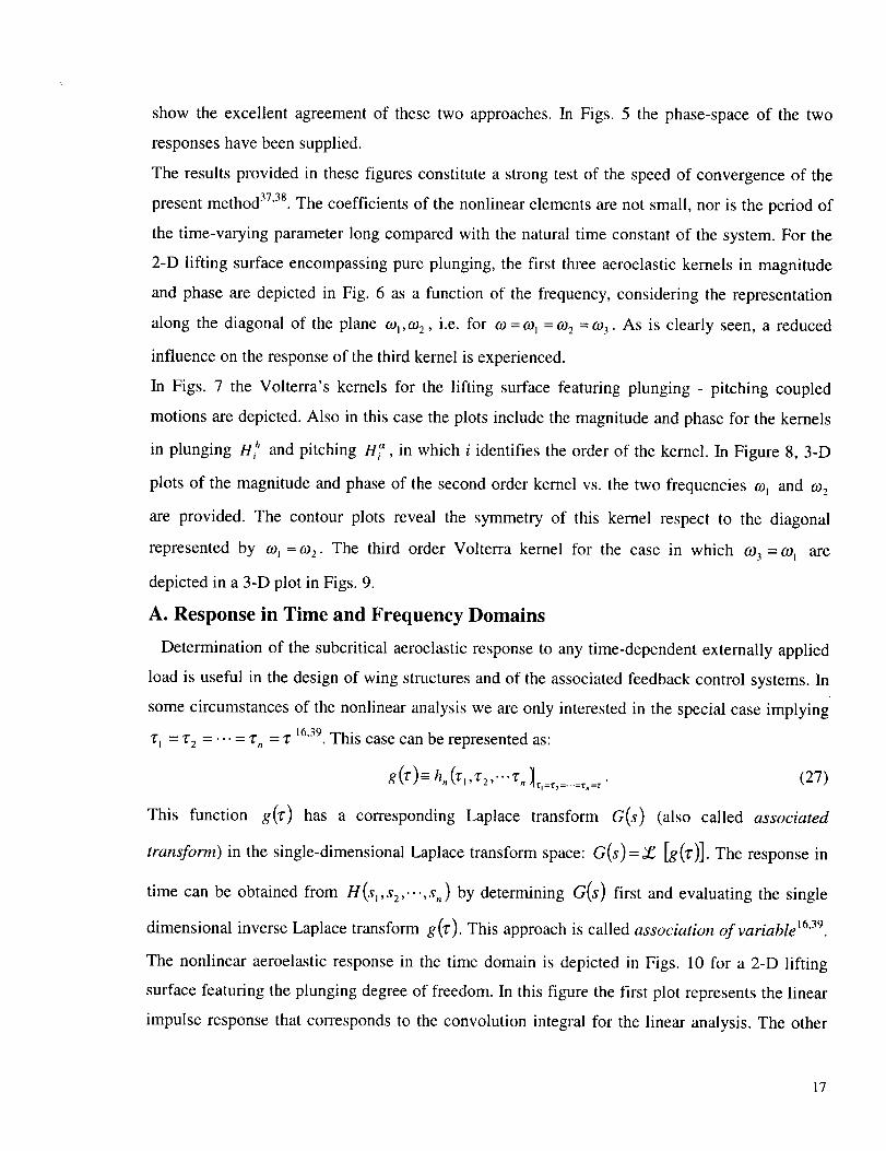
show the excellent agreement of these two approaches. In Figs. 5 the phase-space of the two
responses have been supplied.
The results provided in these figures constitute a strong test of the speed of convergence of the
present method 37'38. The coefficients of the nonlinear elements are not small, nor is the period of
the time-varying parameter long compared with the natural time constant of the system. For the
2-D lifting surface encompassing pure plunging, the first three aeroelastic kernels in magnitude
and phase are depicted in Fig. 6 as a function of the frequency, considering the representation
along the diagonal of the plane c%,co 2 , i.e. for o)= _o1 = c02 = o)3 . As is clearly seen, a reduced
influence on the response of the third kernel is experienced.
In Figs. 7 the Volterra's kernels for the lifting surface featuring plunging - pitching coupled
motions are depicted. Also in this case the plots include the magnitude and phase for the kernels
in plunging H_ and pitching H_, in which i identifies the order of the kernel. In Figure 8, 3-D
plots of the magnitude and phase of the second order kernel vs. the two frequencies c% and co2
are provided. The contour plots reveal the symmetry of this kernel respect to the diagonal
represented by o,)1 = 0)2 . The third order Volterra kernel for the case in which co3 = cot are
depicted in a 3-D plot in Figs. 9.
A. Response in Time and Frequency Domains
Determination of the subcritical aeroelastic response to any time-dependent externally applied
load is useful in the design of wing structures and of the associated feedback control systems. In
some circumstances of the nonlinear analysis we are only interested in the special case implying
2-1 = 2"2 ..... 2"n = 2" 16,39, This case can be represented as:
g (2-)= h, (2-,,2-z,"'2-, ]_,=_2..... _=. (27)
This function g(2-) has a corresponding Laplace transform G(s) (also called associated
transform) in the single-dimensional Laplace transform space: G(s)= _ [g(z')]. The response in
time can be obtained from H(s,,s2,...,s,, ) by determining G(s) first and evaluating the single
dimensional inverse Laplace transform g(2-). This approach is called association of variable 16'39.
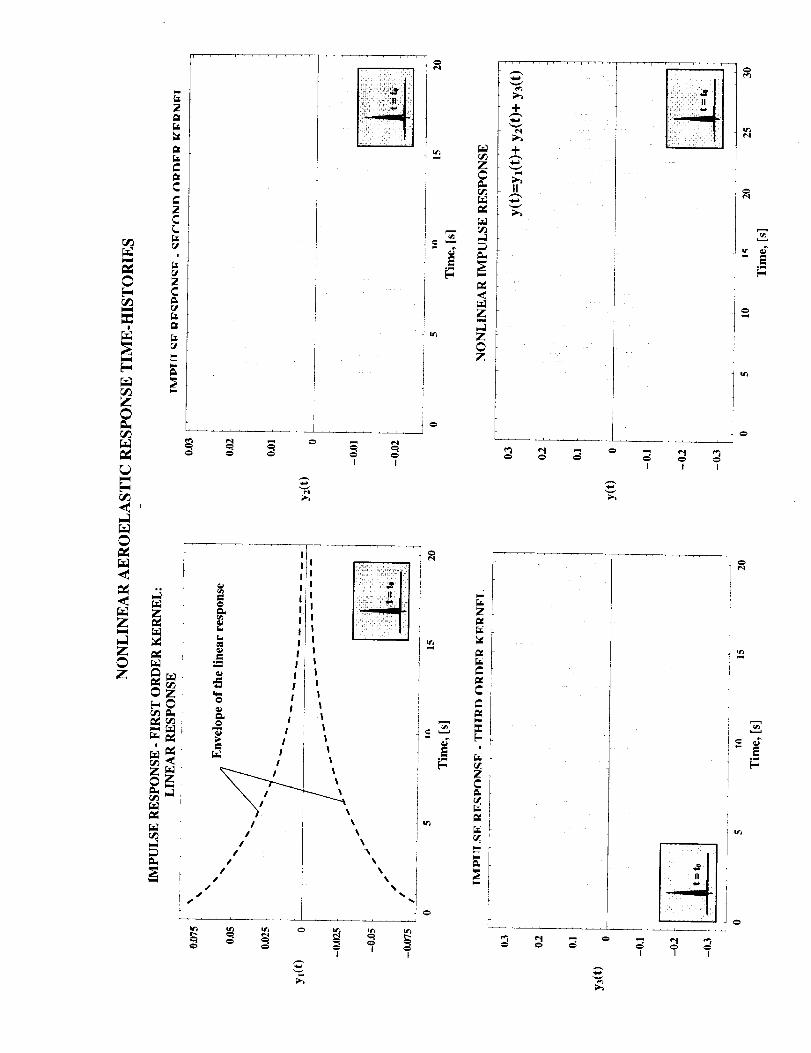
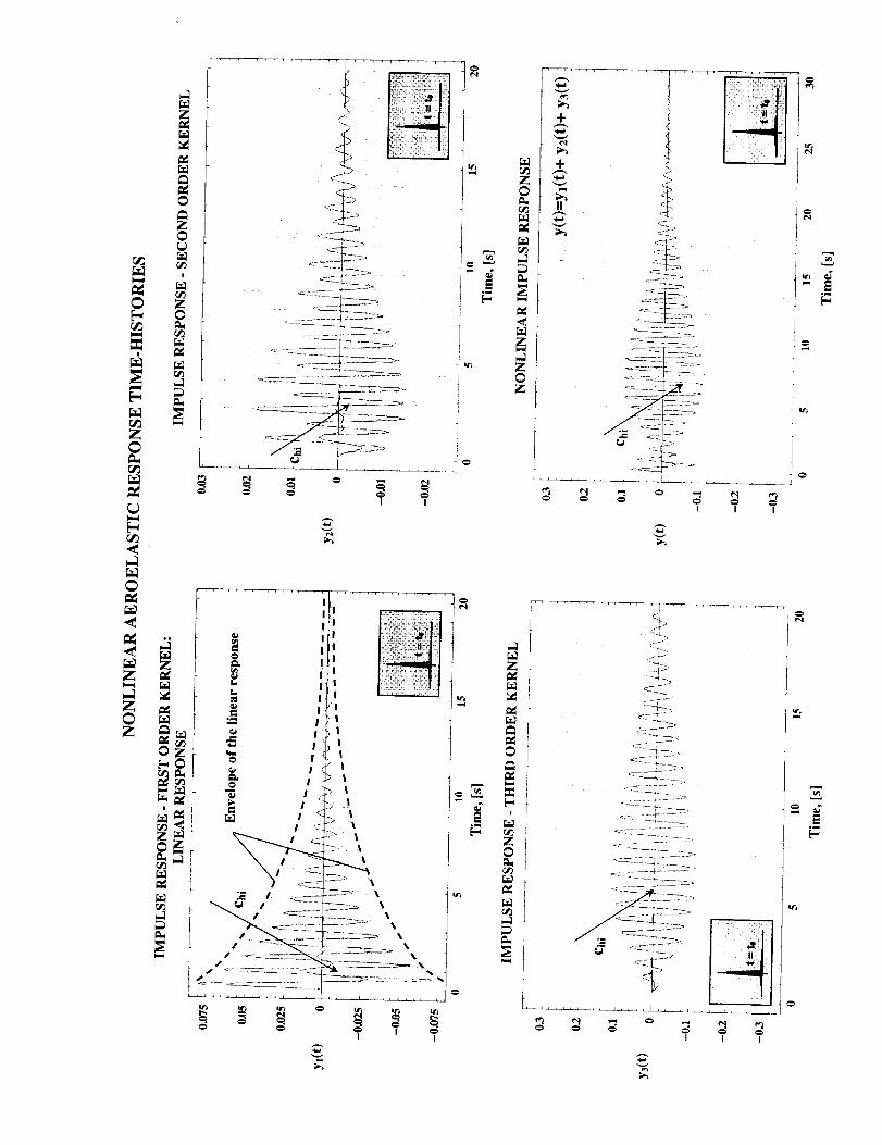
The nonlinear aeroelastic response in the time domain is depicted in Figs. 10 for a 2-D lifting
surface featuring the plunging degree of freedom. In this figure the first plot represents the linear
impulse response that corresponds to the convolution integral for the linear analysis. The other
17

three plots represent the components of the response due to the second and the third order kernels
and the total response as a combination of the three partial responses. The influence of the
stiffness and of the damping coefficients on the response are displayed in Figs. 11 and 12. An
increase of the nonlinear damping or of the stiffness coefficients contributes to the decrease of
the magnitude of the kernels and consequently, of the response amplitude. This shows that the
nonlinearities in the stiffness and damping play a beneficial role on the subcritical aeroelastic
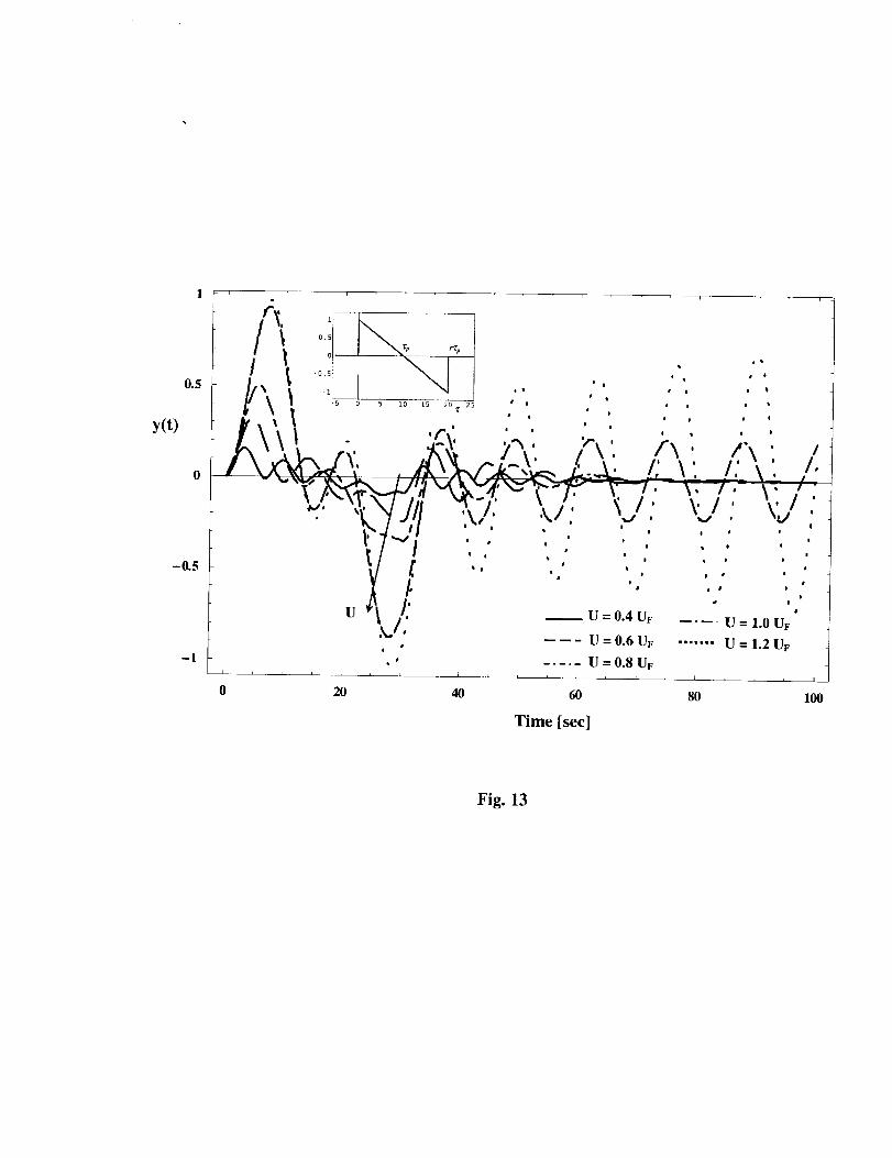
response 18. Figure 13 highlights the effect of the speed parameter V (-U/bo)_) on the lifting
surfaces subjected to sonic-boom pressure signature as shown in the inset. Herein "rl, denotes the
positive phase duration of the pulse measured from the time of impact of the structure; r denotes
the shock pulse length factor. For r - 2 the N-shaped pulse degenerates into a symmetric sonic-
boom pulse, in the sense that its positive phase has the same characteristics as its negative one,
and for r = 1 a triangular pulse that corresponds to an explosive pulse is obtained. It becomes
apparent that the amplitude of the response time-history (that have been evaluated for practical
use with three kernels) increases with the increase of V. Moreover, in a certain range of speeds,
as time unfolds, a decay of the amplitude is experienced, which reflects the fact that in this case
the subcritical response is involved. However, for the dimensionless speed parameter V greater
then the flutter speed (this one was determined using the linearized aeroelastic system), the
response becomes unbounded implying that the occurrence of the flutter instability is impending.
Also in this case the nonlinear stiffness and damping coefficients play a beneficial role on the
subcritical aeroelastic response.
VI. Conclusions
In this work several issues related to the approach of the nonlinear aeroelastic response via
Volterra's series approach have been presented. Following the same approach presented here, the
character of the instability boundary, i.e. benign or catastrophic can also be addressed. It was
also shown that the method based on Volterra series opens large opportunities toward
approaching in an unified and efficient way problems of nonlinear aeroelastic response and
flutter instability. Moreover, this approach can be extended as to include also active control
capabilities. Comparisons of results carried out via Volterra series in conjunction with indicial
functions approach and classical approach have been provided in Fig. 1 for the linearized model.
For the full nonlinear model, such validations have been displayed in Figs. 2-5, in which a
18

comparisonwith the exact digital evaluationof the nonlinear aeroelasticresponsehas been
supplied. In addition, it is worth noting that the aerodynamic indicial functions (for
incompressible/compressibleflow fields) consideredin conjunction with Volterra's series
approachcanbeusedasapowerful analyticaltool for developingunsteadyaerodynamicmodels
and a unified nonlinearaeroelasticmodel. To the best of the authors' knowledge,with the
exceptionof this paper,the problemof the aeroelasticresponseof lifting surfacesto external
pulsesvia Volterra's seriesandindicial functionapproachwasnot yetaddressedin the literature.
Acknowledgment
The partial support of this research by the NASA Langley Research Center through Grant
NAG- 1-2281 and NAG- 1-01007 is acknowledged.
References
1. Librescu, L., and Nosier, A., "Response of Laminated Composite Flat Panels to Sonic Boom
and Explosive Blast Loading," AIAA Journal, Vol. 28, No. 2, 1990, pp. 345-352.
2. Librescu, L., and Na, S., "Dynamic Response of Cantilevered Thin-Walled Beams to Blast
and Sonic-Boom Loadings," Journal of Shock and Vibration, Vol. 5, 1998, pp. 23-33.
3. Department of the Army, Fundamentals of Protective Design for Conventional Weapons,
Technical Manual TM 5-855-1, November 1986.
4. Volterra, V., Theory of Functionals and of Integral and Integro-Differential Equations, Dover
Publications, Inc., New York, 1959.
5. Lee, Y.M., et al., Selected Papers of Norbert Wiener, Cambridge, Mass.: M.I.T. Press, 1964.
6. Rugh, W.J., Nonlinear Systems Theory, The Volterra-Wiener Approach, The Johns Hopkins
University Press, 1981.
7. Schetzen, M., The Volterra and Wiener Theories of Nonlinear Systems, John Wiley & Sons
Interscience, New York, 1980.
8. Boyd, S.P., Volterra Series, Engineering Fundamentals, Ph.D. Dissertation, University of
California, Berkeley, 1985.
9. Lomax, H., "Indicial Aerodynamics," Part H, Chapter 6. AGARD Manual on Aeroelasticity.
10.Bisplinghoff, R.L., and Ashley, H., Principles of Aeroelasticity, Dover Publications, Inc.,
1996.
19

l l.Marzocca,P.,Librescu,L., andSilva,W.A., "AerodynamicIndicial FunctionsandTheir Use
in AeroelasticFormulationof Lifting Surfaces,"AIAA Paper2000-WIP, presentedat the
AIAA/ASME/ASCE/AHS/ASC 41st Structures, Structural Dynamics, and Materials
Conference, Atlanta, Georgia, 3-6 April 2000.
12. Simon, S., and Tomlinson, G.R., "Application of the Hilbert Transform in the Modal Analysis
of Linear and Non-linear Systems," Journal of Sound and Vibration, Vol. 96, No. 4, 1984, pp.
421-436.
13.Chouychai, T., Dynamic behavior of Non-linear structures (linearization, multidimensional
Hilbert transform, Volterra Series), Ph.D. Dissertation (in French). ISMCM, Saint-Ouen,
Paris, 1997.
14.Bedrosian, E., and Rice, S.O., "The Output Properties of Volterra Systems (Nonlinear
Systems with Memory) Driven by Harmonic and Gaussian Inputs," Proceedings of IEEE,
Vol. 59, No. 12, 1971, pp. 1688-1707.
15.Boyd, S., Chua, L.O., and Desoer, C.A., "Analytical Foundations of Volterra Series," IMA
Journal of Mathematical Control and Information, Vol. 1, 1984, pp. 243-282.
16.Brychkov, Yu.A., Glaeske, H.-J., Prudnikov, A.P., and Tuan, Vu Kim, Multidimensional
Integral Transformations, New York: Gordon and Breach, Science Publishers S.A., 1992.
17.Librescu, L., Elastostatics and Kinetics of Anisotropic and Heterogeneous Shell-Type
Structures, Aeroelastic Stability of Anisotropic Multilayered Thin Panels, Noordhoff Internat.
Publ., Leyden, The Netherlands, 1975, pp. 106-158.
18.Librescu, L., "Aeroelastic Stability of Orthotropic Heterogeneous Thin Panels in the Vicinity
of the Flutter Critical Boundary," Part I, Journal de M¢canique, Vol. 4, No. 1, 1965, pp. 51-
76; Part II, Vol. 6, No. 1, 1967, pp. 133-152.
19.Gern, F.H., and Librescu, L., "Synergistic Interaction of Aeroelastic Tailoring and Boundary
Moment Control on Aircraft Wing Flutter," NASA/CP-1999-209136/PT2CEAS/AIAA/
ICASE/NASA International Forum on Aeroelasticity and Structural Dynamics,
Williamsburg, Virginia, June 1999, pp. 719-733.
20.Librescu, L., and Na, S.S., "Bending Vibration Control of Cantilevers Via Boundary Moment
and Combined Feedback Control Laws," Journal of Vibration and Controls, Vol. 4, No. 6,
1998, pp. 733-746.
2O

21.VanTrees,H.L., Synthesis of Optimum Nonlinear Control Systems, The Technology press of
M.I.T., Cambridge, Mass., 1962.
22.Chua, L.O., and Ng, C.Y., "Frequency Domain Analysis of Nonlinear Systems, General
Theory," Electronic Circuits and Systems, Vol. 3, No. 4, July 1979, pp. 165-185.
23.Silva, W.A., "A Methodology for Using Nonlinear Aerodynamics in Aeroservoelasticity
Analysis and Design," AIAA Paper 91-1110-CP, 1991.
24. Silva, W.A., "Application of Nonlinear Systems Theory to Transonic Unsteady Aerodynamic
Responses," Journal of Aircraft, Vol. 30, No. 5, 1993, pp. 660-668.
25. Silva, W.A., Identification of Linear and Nonlinear Aerodynamic Impulse Responses Using
Digital Filter Techniques, Ph.D. Dissertation, College of William and Mary, Virginia, 1997.
26.Silva, W.A., "Reduced-Order Models Based on Linear and Nonlinear Aerodynamic Impulse
Response," AIAA Paper 99-1262, presented at the AIAA/ASME/ASCE/AHS/ASC 40th
Structures, Structural Dynamics, and Materials Conference, St. Louis, Missouri, April 1999.
27.Tromp, J.C., and Jenkins, J.E., "A Volterra Kernel Identification Scheme Applied to
Aerodynamic Reactions," AIAA Paper 90-2803, presented at the AIAA Atmospheric Flight
Mechanics Conference, Portland, Oregon, August 1990.
28.Withoff, D., Austin, W., Wolfram Research, Private communications, 1999-2000.
29.Tobak, M., and Chapman, G.T., "Nonlinear Problems in Flight Dynamics Involving
Aerodynamic Bifurcations," NASA TM 86706, March 1985, pp. 1-15, AGARD Unsteady
Aerodynamics-Fundamentals and Applications to Aircraft Dynamics, November 1985.
30.Tang, Y.S., Mees, A., and Chua, L.O., "Hopf Bifurcation Via Volterra Series," IEEE
Transactions on Automatic Control, Vol. AC-28, No. 1, 1983, pp. 42-53.
31.Mees, A.I., and Chua, L.O., "The Hopf Bifurcation Theorem and Its Applications to
Nonlinear Oscillations in Circuits and Systems," IEEE Transactions on Circuits and Systems,
Vol. CAS-26, No. 4, April 1979, pp. 235-254.
32.Moiola, J.L., and Chen, G., Hopf Bifurcation Analysis: A Frequency Domain Approach,
World Scientific Series on Nonlinear Science, Series A, Vol. 21, Series Ed. L.O. Chua, World
Scientific Publ. Co. Pte. Ltd., 1996.
33.Reisenthel, P.H., and Nixon, D., "Development of a Nonlinear Indicial Model for
Maneuvering Fighter Aircraft," AIAA Paper 96-0896, presented at the 34th Aerospace
Sciences Meeting & Exhibit, Reno, Nevada, January 1996.
21

34.Gifford, S.J., and Tomlinson, G.R., "Understanding Multi Degree of Freedom Nonlinear
System via Higher Order Frequency Response Functions," 7th International Modal Analysis
Conference, Las Vegas, NV, Jan. 30 - Feb. 2, 1989.
35.Gifford, S.J., and Tomlinson, G.R., "Recent Advances in the Application of Functional Series
to Non-linear Structures," Journal of Sound and Vibration, Vol. 135, No. 2, 1989, pp. 289-
317.
36.Worden, K., Manson, G., and Tomlinson, G.R., "A Harmonic Probing Algorithm for the
Multi-Input Volterra Series," Journal of Sound and Vibration, Vol. 201, No. 1, 1997, pp. 67-
84.
37.Ridings, R.V., and Higgins, T.J., "Transient Response Analysis of a Class of Continuous
Nonlinear Time-Varying Automatic Control Systems by Functional Techniques and
Multidimensional Laplace Transforms," ISA Transactions, Vol. 7, No. 2, 1968, pp. 166-172.
38.Chatterjee, A., and Vyas, N.S., "Convergence Analysis of Volterra Series Response of
Nonlinear Systems Subjected to Harmonic Excitation," Journal of Sound and Vibration, Vol.
236, No. 2, 2000, pp. 339-358.
39.Chen, C.F., and Chiu, R.F., "New Theorems of Association of Variables in Multiple
Dimensional Laplace Transform," International Journal of Systems Science, Vol. 4, No. 4,
1973, pp. 647-664.
22
Figure Captions
Fig. 1 Aeroelastic response to Dirac delta impulse, as represented in inset. Comparison of
response prediction based on the first Volterra kernel and the exact solution
(m = 1;Chl = 0.1; khl = 102 ;b = 1;p = 0.125; U® = 0.4UF;CL_ = 2zr).
Fig. 2 Convergence study involving the first three kernels and comparison with the "exact"
nonlinear aeroelastic response to a 1-COSINE gust pulse, as shown in the inset; parameters as in
Fig. 1.
Fig. 3 Convergence study involving the first three kernels and comparison with the "exact"
nonlinear aeroelastic response to a triangular blast load, as shown in the inset; parameters as in
Fig. 1.
Fig. 4 Convergence study involving the first three kernels and comparison with the "exact"
nonlinear aeroelastic response of the impulse response described in Eq. (26) (A = 1;R = 1;k = 1;
e =l;to o = 2re).
Fig. 5 Convergence study involving the first three kernels and comparison with the "exact"
nonlinear aeroelastic response of the impulse response described in Eq. (26) (phase-space
representation ) (A = 1;R = 1;k = 10;_ = 1; to,, = 207r).
Fig. 6 Comparison of the first three aeroelastic kernels for pure plunging motion
(m = 1;Cht = 10; khl = 104 ;ch2 = 10; kh2 = 107 ;ch3 = 10; kh3 = 10t°;b = 1;p = 0.125; U_ = 0.4U F ;CL,_ = 2re).
Representation for sj = s 2 = s 3 , i.e. coj = co2 = 093.
Fig. 7 First two aeroelastic kernels for plunging - pitching coupled motion (m = 1;a = --0.2;Chl = 10;
(khl = 104 ;C,_j = 10; k_,l = 104 ; ch2 = 10; kh2 = 107 ; c,_2 = 10;k_2 = 107 ;b = 1; p = 0.125; U _ = 0.4U F ; CL,, = 2_Z).
Fig. 8 3-D and contour plots of second order aeroelastic kernel; parameters as in Fig. 6.
Fig. 9 3-D and contour plots of third order aeroelastic kernel; parameters as in Fig. 6.
Fig. 10 Time-history of the nonlinear aeroelastic response (U = 0.4U F ; CL,_ = 2zr; m = 1;Ch_= 10;
khl = 104 ; ch2 = 10; kh2 = 107 ;Ch3 : 10; kh3 = 10 l° ;b = 1;p = 0. i 25).
Fig. 11 Influence of the nonlinear stiffness coefficient khi on the nonlinear aeroelastic response;
parameters as in Fig. 7.
Fig. 12 Influence of the nonlinear damping coefficient Chi on the nonlinear aeroelastic response;
parameters as in Fig. 7.
Fig. 13 Influence of the flight speed on the nonlinear aeroelastic response to a sonic-boom
('t-p = 15 sec; r = 2), as shown in the inset, evaluated with three kernels; parameters as in Fig. 7.

LINEAR AEROELASTIC RESPONSE TIME-HISTORY: COMPARISON
0.075 !
[F
_05 L
y(t) 0
-0.025
-0.05
--0.075
,"l %
%
f?-
[
i
L / !i
i ! ' iI
4
]
LIL J _'
i I s
Linear Response via
Convolution Integral
Linear Response with First
Volterra Kernel Hl(ol)
L
0 2 4 6 8 10
Time [sec]
Fig. 1

y(t)
0.3
0.2
0.1
-0.1
/ \ 1_̧ !_/ °i'
0 5 I0 15 20%. 2
.... First Approximation _. _/" _" -
..... Second Approximation _. r
..................Third Approximation
Exact Response (Num. Int.)r , L h ,
0 0.5 1
JL J J L--
1.5 2 2.5 3
Time [sec]
Fig. 2

0.3 S\ .... First Approximation
\ ..... Second Approximationr \
0.25 / \_ ..................Third Approximation
/ /", \ -- Exact Response (Num. Int.)
y(t) 0.2 _i\ \0.15
o.1 _ ', \, \ °_
o.o_ _\ \Z °+ '° _2+
' J I I I I
0 1 2 3 4 5 6
Time [sec]
Fig. 3

/ i
/ Ii
ii_
Z
.<
Z
_ L L I
! i
I "-" I
- i ' J
N
Z_
//
//
/
/
/
,'/' //
..'/,/
I
,Ii J
; ;ill_II
i iii_i_i _i_i!_i_
\
e4
e4
I
//
//
[-
\
\/
/
¢'t
I
,
/' S
.9
.9
•_ "_o
i, II II I
/
/
/
//

UNSTEADY AEROELASTIC KERNELS
0.8
0.6
0.4
0.2
0
MAGNITUDE [103]
First Order Kernel Hi(con)
Second Order Kernel H2(o_n, _2)
Third Order Kernel H_(c01, oh. oh) \ / 't
60 80 1000 20 o_n/3
!
40 co1/2
Frequency, 0.)1=0)2:_t)3:0,), [Hz]
120
PHASE [deg]
150
100
50
-50
-100
- 150
Second Order Kernel
H2(o_n, co2)
i 1I
iI iI
i L L _ i J i ,
0 20 40
i i
:r .\\
,t
Hl(0)l)
i i
6O 8O
q\
Third Order Kernel
H3(co_, co2, o>j)
100 120
Frequency, co_=co2=¢o3=c_, [Hz]
Fig. 6

E
tE
r_
Jml
,lq
$
/
\
r
_L
$
li
L,
il
L.
/
ys
y,
\
_L
_ 1 1 J J J i i , b k L J , , i , , _ _ , , , i
i..--i
II
il
L.
II
II
G_
fu

I
-r
I
I
I
I
I
I
I

Z
G,a
h_a
I
=
E--
Z0
0
Z0Z
C
C
C
fJ
OZ
!
C_
z_
I I
=O
_aL_
I--
_a=
°N
_a
0
e_0
I
II
I
/
t
t
I
JJ
I I
Z0
0
C
Z_C
+
+
II
I I I
I I I
7
]
.t =
E-

i:1
|
I
0
Z0r_
S
S %
I i
÷
+
I I I
I I I
p
0
r_Z0
r_
0
Z0Z
Z
0
Z0
r_ZO
N
I I
z I0Z
L , i
0.5
y(t)
-0.5
-1
14 [ J
' _°i....._'_" . .,,..":,":!/_, _ 1 1 ...... " , . ,g \ 'T ._o _ _o,__o_ ,, ., .,, ,,If_. _, ._' , , ' ' . , . .I \ \ I . .7-_, ,.'_, >., r. , _.. , /rx 'A F, r_', ,2A_ _.L \ , l \: /! "_, i, \, /,
\_'JW -'_, ' ,-&_" "x"G'*" "_', ._-="K-. --'_-:'- "'->- ,.
y_ '. ,., .,: :,,._'_ / " '
U i, _ U=0.4U_ .... U= 1.0 U_
t_l: ----- U = 0.6 UF ....... U = 1.2 UF
...... U=0.8 Uv
0 20 40 60 80 100
Time [sec]
Fig. 13