Embed Size (px)
Citation preview
AIAA 2000-WIP
Aerodynamic Indicial Functions andTheir Use in Aeroelastic Formulation
of Lifting Surfaces
Piergiovanni Marzocca and Liviu LibrescuVirginia Polytechnic Institute & State University,
Blacksburg, VA 24061
Walter A. Silva
NASA Langley Research Center
Hampton, VA 23681
41 St AIAAIASMEIASCEIAHSIASC
Structures, Structural Dynamics,and Materials Conference
April 3-6, 2000 / Atlanta, GA
For permission to copy or to republish, contact the American Institute of Aeronautics and Astronautics,1801 Alexander Bell Drive, Suite 500, Reston, VA, 20191-4344.
https://ntrs.nasa.gov/search.jsp?R=20010029662 2018-09-14T00:28:11+00:00Z
AIAA-2000-WIP
AERODYNAMIC INDIClAL FUNCTIONS AND THEIR USE IN AEROELASTICFORMULATION OF LIFTING SURFACES
Piergiovanni Marzocca" and Liviu Librescu _
Virginia Polytechnic Institute and State University, B lacksburg, VA 24061-0219,
Walter A. Silva*
NASA Langley Research Center, Hampton, VA 23681-2199.
ABSTRACT
An investigation related to the use of linear indicialfunctions in the time and frequency domains, enabling
one to derive the proper aerodynamic loads as to studythe subcritical response and flutter of swept lifting
surfaces, respectively, of the open/closed loopaeroelastic system is presented. The expressions of the
lift and aerodynamic moment in the frequency domainare given in terms of the Theodorsen's function, while,in the time domain, these are obtained directly with the
help of the Wagner's function. Closed form solutions ofaerodynamic derivatives are obtained, graphical
representations are supplied and conclusions andprospects for further developments are outlined.
NOMENCLATURE
a, Dimensionless elastic axis position measured
from the midchord, positive aft
c, Chord length of wing, normal to the elastic axis,
2b,,
CL,_, Lift-curve slope
fh, fa Plunging and pitching deflection functions
h, htj Plunging displacement and its amplitude,
respectively
I,_ Mass moment of inertia per unit length of wing
l Wing semi-span measured along the midchordline
Ih Dimensionless aerodynamic lift, Lhb/mU _
Aerospace Engineer, Ph.D. Student.t Professor of Aeronautical and Mechanical
Engineering, Department of Engineering Science andMechanics.
* Senior Research Scientist, Senior Aerospace
Engineer, Aeroelasticity Branch, Structures Division,Senior Member AIAA.
Copyright © 2000 The American Institute ofAeronautics and Astronautics Inc. All right reserved.
Lb,l b Overpressure signature of the N-wave shock
pulse and its dimensionless counterpart,
Lbb/mU _ , respectively
m Airfoil mass per unit length
m a Dimensionless aerodynamic moment, M,_bZ/Ic, U_
N Load Factor, h"/g
P,,,fo,, Peak reflected pressure in excess and its
dimensionless value P,,b/mU_ , respectively
r Shock pulse length factor
ra Dimensionless radius of gyration, (I_,/mbZJ '2
s,_" Laplace transform variable and operator
Sa, Z,_ Static unbalance about the elastic axis and its
dimensionless counterpart, S,_/mb
t,'c o Time variables
U, U,, Freestream speed and its component normal to
the elastic axis
V Dimensionless free-stream speed, U/bco,_
x Coordinate parallel to freestream direction.7 Chordwise coordinate normal to the elastic axis
y Coordinate perpendicular in the freestreem direction
7 Spanwise coordinate along the elastic axis
w Downwash velocityz Transverse normal coordinate to the
midplane of the wing
Z Vertical displacement in z direction
a, a o Twist angle about the pitch axis and its
amplitude, respectively
_h,_,_ Structural damping ratio in plunging, G/2mCOh
and in pitching, c,_/21ao G
7?
A
/1
¢
Dimensionless coordinate along the wing span, y/l
Spanwise rate of change of twistSwept angle (positive for swept back)
Airfoil/air mass ratio, m/zrpb 2
Dimensionless plunge coordinate, h/b
American Institute of Aeronautics and Astronautics
P
O"
7
"L'p
o),k.
Air density
Spanwise rate of change of bending
Dimensionless time, U,t/b,
Dimensionless positive phase duration of the
pulse, measured from the time of the arrival
Circular and reduced frequencies, o)b /U,,
o_h,waUncoupled frequency in plunging,(Kh/m) 112
and pitching, (K_/1 o ),,2
Plunging-pitching frequency ratio, ogh/_o .
Subscript
( " )c Circulatory terms of lift and aerodynamicmoment
( • ),cNon-circulatory terms of lift and aerodynamicmoment
(.), Quantity normal to the elastic axis
A( " ) Quantity associated with the swept wing
Superscript
^
( ) Variables in Laplace transformed space
( ), ( • ) Derivatives with respect to the time t, and
the dimensionless time z, respectively
INTRODUCTION
In this paper, the linear indicial functions in the time
and frequency domains are used to determine the
corresponding unsteady aerodynamic derivatives forswept lifting surfaces. Such a treatment of the problem
enables one to approach either the open/closed loop
aeroelastic response in the subcritical flight speed
regime to arbitrary time-dependent external excitations
(such as e.g. gusts, airblasts due to explosions or sonic-booms), or the flutter instability of actively
controlled/uncontrolled swept wings. Moreover, this
study is intended to extend its scope as to include, by ananalogous procedure, the case of the various flight
speed regimes, i.e. in addition to the incompressible
one, also the compressible, transonic (within the
linearized concept of indicial functions), and
supersonic.
The representations of the aeroelastic governing
equations in the time-domain is useful toward the
approach of both the subcritical aeroelastic response of
the actively controlled/uncontrolled swept aircraft
wings. In other worlds, in this framework, the
open/closed loops dynamic response of aeroelastic
systems can be analyzed.
The unsteady aerodynamic lift and moment in
incompressible flight speed regime are expressed for
the swept aircraft wing in the time and the frequency
domains by using the Wagner and Theodorsen
functions, respectively. For the response of dynamic
systems it is only necessary to express the lift andmoment via the indicial Wagner's function. For the
approach of the flutter problem, the Theodorsen'sfunction helps the conversion of the expressions of both
the aerodynamic loads and the unsteady aerodynamic
derivatives in the frequency domain. Herein the case of
a 2-D lifting surface, including the plunging and
pitching degrees of freedoms is considered•
PRELIMINARIES
In the next developments an extensive use of variables
in both the time and frequency domains will occur. Asshown in Edwards, Ashley & Breakwell 3, for zero
initial conditions, the aeroelastic equations can be
converted from the time to the frequency domain via a
Laplace transform. This results in the possibility of
using the correspondence s ---) ik,, where s and k, are
the Laplace variable and the reduced frequency,
respectively. The Laplace transform operator .Z' isdefined as:
,,_( . )=_(.)e-"¢d'_. (I)
In this sense, the Wagner's function _('r) is connected
with Theodorsen's, function C(k,) via Laplace
transform as:
-- -iknfC(k.) F(k.)+ia(k.)__¢(r) e dz=dP(ik.),ik. ik.
and vice-versa:
(2)
-1
_(z') = ,,T {C(k.)/ik.}, Re(ik.)> 0. (3)
and having in view the correspondence s _-_ ik, we can
also write:
*(ik.)ik_.._s IT_O(r)e-'_dz = *(s), (4)
Using this relationship, it is possible to obtain the fullexpression of unsteady aerodynamic coefficients in
American Institute of Aeronautics and Astronautics
termsof the Theodorsen's function C(k.) and its
circulatory components F(k.) and G(k.).
It is interesting to note that the reduced frequency
parameter k. for swept and for straight wings coincide:
where h - h(_;,t), a --a(y,t) are the displacements in
plunging and pitching, respectively, and the origin ofthe 2 axis coincides with the elastic center, the
downwash velocity w normal to the lifting surfacebecomes:
k. - rob. _ cobcosA _wb=k ' (5)U. UcosA U
iox = ik.z . (6)
This implies that the indicial Wagner's function O(z')
remains invariant to any change of the sweep angle.
ANALYTICAL DEVELOPMENTS
For swept wings, the total lift per unit span, can be
expressed in the form:
A Lh(-Y,t)=ALc(y,t)+AL,,.,(Y,t)
+AL,c:(y,t)+AL,,.3(Y,t)" (7)
where the indices c and nc identify the various
contributions associated with the circulatory andnoncirculatory terms respectively.
Using similar notations, the total moment per unit spanabout the elastic axis is:
AMa (Y,t)=AM_ (y,t)+ ^M,c,(y,t)
+aM,,.z(y,t)+^M,c3(y,t)+AMa(y,t ), (8)
^ M a (y,t) being associated with the apparent moment
of inertia. Herein the lift is positive in the negative zdirection (considered positive downward), while themoment is positive nose up. For the sake ofconvenience, herein the plunging coordinate is positive
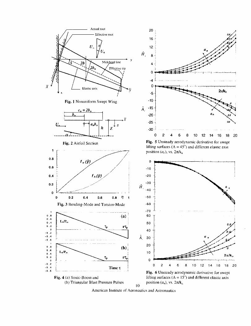
when is downward (see Fig. 2).
Using the expression of the lift (Eq. (7)), the equationfor the moment, Eq. (8), can be cast as:
n M_(y,t)=-(1/2 + a.)b. AL,.(y,t)-a.b. AL._,(y,t)
+ (1/2 - a. )b. ^ C.,.2 (y,t)+AM.c 3 (-y,t)
+^ M, (7, t). (9)
w(x, y,t)=w('_, y,t)=oTZ/o3t +U=OZ/O2. (11)
In conjunction with the definition of Z, (Eq. 10), Eq.(11 ) becomes:
w(Y, y,t):/_ + 26_ + U _cosA
+ U (Oh�off + 2o-_a/off)sin A. (12)
where the superposed dots denote the derivatives with
respect to time t. The quantity in Eq. (12) undescored
by a solid line is usually discarded in the specializedliterature (see Bisplinghff, Ashley & Halfman2), as
being related with the wing camber effect (see alsoFlax ). However, herein this quantity will be included.
The in-plane coordinate 2 normal to the elastic axis
(see Fig. 1) can be expressed as:
2=b,,(l/2-a,,). (13)
Consequently, using the dimensionless time'r(-- U.t/b. )
Eq. (12) becomes:
h' + 3h tanAw(Y,y,z):U,, b,---_-+a off.
+(l/2-a,, a'+b --tanA.o_ , (14)
where(4---In the following sections, the unsteady aerodynamic
loads in incompressible flow can be obtained in timeand, with the use of the Laplace transform space, in the
frequency domain.
Unsteady Aerodynamic Loads in IncompressibleFlo._.._w
Time Domain
Basic Considerations
Expressing the vertical displacement Z of a point on thecenter line of the wing as, (Fig.2):
Z(2, _7,t)= h + _a, (10)
The circulatory components of the lift and momentexpressed in term of Wagner's indicial function _0('r)
(called also herediO' function) obtained in the timedomain are:
3American Institute of Aeronautics and Astronautics
AL./ + CLo
(_; ):22AM_(y,V)= +a,, L,, b,,pU,,
-= Oz°
(15)
(16)
As concern the aerodynamic non-circulatory
components, using the dimensionless time r these are
expressed as:
^L,,c,(y,'r)=-l CL,_.pU2.,[h'-a.b,,d'], (17a)
½ 2 ,a L,,c2 (_;,'r)= - CL,_°pU,,b,,ot, (17b)
^L.c3(Y,_:)=-I cL_,.pU2.b_, tanA r +1 +'SrZ
+ tSr 00" tan A] + ICe _ -U2b 3off J 2 "/" " "
+ Sr 0k tan A / .off 3
tan r +
(17 C)
The moments induced by the non-circulatory
components of lift are expressed using thedimensionless time as:
AM,,c,(y,'r)=l cL_.pU2[h"-a,,b,,ot"]a,,b,,, (18a)
AM"c2(Y"r)=-ICL_'2 "PU'_b'_(1-a_2 ,, ):t' , (18b)
231 nAa M,,c3('_,r)=-2CL_,.pU,,b,, -_ Ata
1 2 3 ff "+-_CL_,pU, b,a . tanA (6, +l)._----+6r ).bn
+ar-gtanA - CLoPU b'.
tanAI(tSr +l)'A--_"+t_' _-tanA]/9 , (18c)
--2-,2 A,^M.(y,r)=- pC_ v.u.a . (18d)
as in the following ones, the terms affected by the tracer
t_ identify those generated by the last term in the
expression of the downwash velocity (Eq. (12)), (termunderscored by a solid line). In general these terms are
discarded being considered negligibly small (see
Bisplinghoff et al. 2, and Flax4), in what case S, = 0,
otherwise S_ = I. Replacement of Eqs. (15) and (17) in
Eq. (7) and of Eqs. (16) and (18) into Eq. (8), results in
the unsteady lift and aerodynamic moment expressed in
the time domain. Concerning the circulatory parts of thelift and aerodynamic moment, Eqs. (15) and (16), these
can be explicitly determined by transforming theseexpressions in the Laplace domain using therelationship between the Laplace transform of the
Wagner and Theodorsen functions, namely
C(-is)Is = _/'(_(z)) = qb(s), and afterwards inverting
back the obtained expressions in the temporal space.
Alternatively, in order to ease the computations, the
available approximate expressions for _('r) (see
Edwards et al. 3) can be used in the Laplace transform
process.The expressions of lift and aerodynamic moment in the
time domain, ^ Lh (y, r) and AM,_ (y,'r) can be used to
determine the subcritical aeroelastic response of swept
wings. However, when the aeroelastic response oflifting surface to time-dependent external pulses, isneeded, the unsteady aerodynamic loads in the time
domain,^ L h and A Ma, have to be supplemented by
the ones corresponding to above mentioned pulses.This will be considered in the next developments and a
simplified illustration of the capability of this methodwill be given in this work.
Laplace Transformed Space
Several preliminaries related to Laplace transform
applied to aeroelastic quantities will be given next.
A{L_(y,s_M_(y,s)}=
=ff {AL_(y,Z_A M_(y,z)}e-'_dz. (19)
We will express the Wagner's function and theplunging and pitching degrees of freedom in the
Laplace transformed space as:
¢(t fz_ O(s ) h(t )_'_ f_(s ) ot(t )_zT_&(s )
where the spanwise rates of change of bending and Considering zero initial condition, Laplace Transformed
twist, cr and ,q., respectively, are expressed as counterparts of Eqs. (15) and (16) are."a = cgh/off and A. = &t/off. In these equations as well
4
American Institute of Aeronautics and Astronautics
_ 212i^Lc(y,s ) CLab,,pU,, --+ sc2+ so" tan A +=- s bn
I 1 IsZ&+b,,s_.tanA))_(s) (20,+ -- a.
_-+ s& + scr tan A
+ 2 "
Herein, and in the next expressions, the plunging andpitching motions in the Laplace domain are expressed
as /] = h(y,s)and c_ -a(7,s).
The Laplace transformed counterpart of Eqs. (17) canbe expressed as:
_ i 2 2 [/__ anbnt_],h Lnc, (Y, s)= -_ CLa" pU ns (22 a)
(7,s)=-_CL_.PU_.b°s_,L.c2 (22 b)A
^<_,(7,s)=- C_o.pU_.b_.tanA l+a_)__,+,_ZOn
+S.-_tanA]+lcL,_.pU_b3tanA[(l+S_)-_s
+ 8_ _9_ tan A]. (22 C)
J
The Laplace transformed counterpart of Eqs. (18) canbe written as:
AM...,(7, s)=lcL_.pU2s2[£[email protected]., (23a)
AM""z(7's)=-I cLa2"PU'_b'_(I(2 -a,, _t_ , (23b)
M.c 3 (y, s)= _1 CL_. pU2b 3 1 _ tan A^ 2
+-CL,_.pU,,b,,a,, tanA 6_ +1 s+¢5,_.+2
+ _ ¢9°" tan A] Ioff (1 2/-_CL_.pUZb4. +a. tanA
[ (6r +i)b-@ s +'r 0& tanA]off ' (23 c)
_6 t2rr2 2 ^^M,,(y,s)=- pCL_v.tJ.s a. (23 d)
The equations of lift and aerodynamic moment help usto perform the conversion in the frequency domain.This will be done in the next section.
Frequency Domain
Upon replacing s _ ik, in Eqs. (22) and (23); using the
relationship between Laplace transform of Wagner andTheodorsen's functions (Eq. (2)); representing the time
dependence of displacement quantities as:
o_(7,r)= f,_(y_(r,k,)= fa(7)t_o e_'"r , (24a)
h(y,"c)= fh(Y)h(r,k,)= fh(7)hoe ""_ , (24b)
and expressing:
^ L_(y, k.,v)=^ T_(y, k. )e""_ , (25a)
^ M_ (y, ko, r)=^ M-o (7,/¢. )e*'"', (25b)
the equations for the unsteady lift and momentamplitudes can be expressed in the frequency domain.
These expressions that coincide with the ones obtaineddifferently in Barmby et al), can be used in the flutter
analysis of swept aircraft wings.
In this analysis f,_ (7) and f_ (7) are chosen to be the
decoupled eigenmodes in plunging and twisting of thecounterpart structure, and are determined as to fulfill
identically the boundary conditions. Using the spanwise
dimensionless coordinate 7"/= y/l, these are expressed
as:
sinh fll + sin fljfh (7) = Fh (7"/)= C, ((cos fl,r/- cosh fl,r/) cosh /31+ /3,COS
+ sinh fl_r/- sin fl,r/) (26)
f_ (_;)= F,, (r/) = Cz sin flzr/, (27)
where for the first bending and torsion we have
fll =0-5969rc and f12 =n'/2.
The constants C_ and C a are chosen as to normalize
fh (Y) and f,_ (7), and so to get the unitary maximum
deflection at the wing tip. The uncoupled first bending
and torsion mode shapes needed for the evaluations ofthe aerodynamic lift and moment are shown in Fig. 3.
The following expressions will be useful in the nextdevelopments:
z'- °_'_ - oYo(y)_ .. ,,.,off_ off 6t°tg"e ' (28)
5American Institute of Aeronautics and Astronautics
"- c92h - °3fh(Y)h,,ik.ei_"_ (29)cr of_ 037
_" - °_2fa (Y)_0e i'"r , (30)
cgff ,9 2fh (Y) hoei,._ "off- off z (31)
Unsteady Aerodynamic Derivatives in theFrequency Domain
At this point, a careful inspection of Eqs. (7) - (8),suggests the following representations for the lift and
aerodynamic moment:
/ h'ALh(Y,k.,v)= pU2.2b, k.Hl--+k.H_a'+k_H_a
bll "
+k2H. h+ H a'+ H. (32)n b _
AM_(y,k.,r)= pU,_2b k.A,--+k.A2a +k,,A3ab n
+ k 2A4 .h__+A,a. + h" )A 6 -- . (33)
t_. " b.
Herein the dimensionless unsteady aerodynamic
coefficients H_, A_ have been introduced, and k_ has
been included as to render the quantities in brackets
nondimensional. Herein, b. is the half-chord of the
airfoil and U. is the component of the flow speed, both
normal to the elastic axis.
In a simplified context, such a mixed form of the liftand moment was used in Simiu & Scanlan 9, and
Scanlan 8. The unsteady aerodynamic derivatives for
swept wings are obtainable from the previous equationsof lift and aerodynamic moment, by assuming harmonic
time dependence of displacements quantities. In such away, the frequency domain counterpart of Eqs. (32)-(33), expressed in compact form, becomes:
A-Lh(_,k.,T)= pU2kZb.(_Ll +aoL2 ), (34)
AM_(y,k.,z)= pU.k.b._b. , +aoM2 . (35)
Herein, the unsteady aerodynamic complex coefficientsL, and Mi can be expressed as:
LI =iI21, +I_I4 ; Lz =ii212 +/-)3 (36)
M 1 =i.4_ +'_4; M2 =iA2 +'_3- (37)
6
American Institute of Aeronautics and Astronautics
where, for the sake of convenience, the unsteadyaerodynamic derivative are written as:
1711=H,;IBIz = H2;/43 =(H 3 - H5);,/4 , =(H 4 -H6),
'41 = A, ;'42 = A2 ;A3 = (A3 - A_ ); '44 = (A4 - A6 ). (38)
The unsteady aerodynamic derivatives in the frequencydomain for swept wing will be obtained from the
following equations, expressed in terms of Wagner'sfunction _(ik.). Comparing Eqs. (36) with that
expressing the lift in the frequency domain, yields:
1 I Ccc_ [-
"b n tanAL(t5 + l)_-_-_-I_ikLl=-2 CLa°fh 2 k_ oy.
+6_b_tanA +----_*(ik. kJh-ib . tanAk n
(39 a)
L 2 = - --" _[ik. iif_ tan A
+lcLaa._2 tanA[(_+l)--_ik_+S_bn-_f_-tanA],kn off
b. Ofa tanA- CLaa_f _ 2 k. f_"-6_ c_°k_ _
(39 b)From a similar analysis, comparing the Eqs. (39) with
that expressing the aerodynamic moment in frequencydomain, yields:
Ml=-CLc_"(l+a_(iknlk_fh-ib_, tanA]k__2
-1CLa. anf h 1CLc_" a b+ 2 k_ " " tanA
(_r +1) ik_ -, o_o_ ----_--T-2tan A , (40 a)
M_= kn _2 " (ik.)
Iifa-ll-a_Iknfa-ib.-_tanA)]+76C_a. fa
(1 |_ __"_1 C/.a.. +/2C_a. anfa2 1 CLa Ofa_ . bn-an)2 kn ifa 2 k2n off
tan A I--- --" b_|-+a_ tanA-_an) 2 k_ 18
0 :f,_ A]. (40[(8_+l)_Tik,,+_b,--_--2tan J b)
UsinginEqs(39)-(40)equations(2),separatingtherealandtheimaginarypartsoftheaboveexpressions,theunsteadyaerodynamicderivativesresultas:
= . _an (kn)fa+ fa+'_f.k,,
+b"-_. tana(2G(k")(l-a")-2a"(l+_')]l'_, k. ,2
"_ k. k. t.2
+_-_z _a tanA(F(k'(l-an)+lark.off,
1 b2 c)2fa 2 ]"-a.a. 2/<z _2 tan A
( G(k")fhk. b. k 2tanA [ F(k,, ) _.__D.h/-}4 = Ct.a. lfh +
+,rLb a2fh- "))_tanA (41)
2"_-
/q = Cta"k._ 2((l+an )F(k.)fh +b.--_Ttan A
_2=CI.a. (¢an 1 +[l+a n2,.,,-+-( a2"-I) 2F(k")f_ +b_ OfatanAo_
;3 =_((l + 2an)2F(kn)fa +(4a2-1)U(kn)knfa
1 2 + -_--tanA((1-4a}+( 202 +-_.fa b. -_ )F(k.)
A4=--CLa.(lanfh+(l+an_. n)fh-_-_2tanAkn
((l+a._(k.)_+'.la,,b._tanA)) . (42)
The coupling terms, due to the sweep effects, areseparated in the overall expressions of aerodynamic
derivatives. For A = 0 the expressions of aerodynamic
coefficients corresponding to straight wings areobtained. The unsteady aerodynamic derivativesrecorded above coincide with the ones obtained
differently in Barmby et al. l, where the spanwise rates
of change of bending and twist, or and A,, that are
associated with the sweep effect, also intervene. When
specialized for 6r = 0, there coincide with the ones by
Bisplinghoff et al. 2
Aeroelastic Response of an Airfoil FeaturingPlunging and Pitching Coupled Motions to Sonic-Boom Pressure Pulses.
An applications on the aeroelastic response of an airfoil
in an incompressible flow featuring plunging andpitching coupled motions to sonic-boom and blast
pressure pulses will be given in the next developments.The aeroelastic governing system of equations of anairfoil featuring plunging and twisting degrees of
freedom to sonic-boom, blast pressure pulses, expressedin dimensionless form, can be cast as:
¢ "(r )+ Z_,a"(r)+ 2(h (w--IV)_ "(r)
+(_/V)2¢(r)_lh(r)=lb(r) '(43)
/ r2 "(r)+a"(r)+(2¢=iv )+ Iv 2 (r)=0
(44)
In the above expressions this following dimensionlessparameters have been used:
l,,=l_,,blmU2 ; go,.= ,,,blmU;., V=U®lbw<,,
tx = mlsrPb 2 ; (,. = c,,12mo9,. ; _ = og_lwc. ;
a,_=(_U.,)"2; <o_=(K_II:J'2; (: =c=121<,w";
r==O=l,',b_l'_; zo=Solmb; mr,=M:a=Is=u_..
The dimensionless sonic-boom overpressure signatureof the N-wave shock pulse, can be described as follow:
Herein, the Heaviside step function H(r) has been
introduced in order to describe the typical pressure
time-history for blast or sonic-boom loads; 6 b is a tracer
American Institute of Aeronautics and Astronautics
thatshouldbetakenasonewhenthesonic-boomisconsidered,andzerowhentheblastloadis included;_,,denotesthedimensionlesspeakreflectedpressureinexcessof theambientone;rr denotesthepositivephasedurationof thepulsemeasuredfromthetimeofimpactof thestructure;r denotes the shock pulse
length factor. For r = 1 the N-shaped pulse degeneratesinto a triangular pulse which corresponds to anexplosive pulse (Fig. 4.a), and for r = 2 a symmetric
N-shaped pulse is obtained. A depiction of lb/oeO,,,VS.
time is displayed in Fig. 4.b.The Eqs. (43) and (44) can be converted in the Laplace
transformed space and solved for their unknowns,
_(-f (4)) and &(=_' (a)); inverted back in time
domain one obtain the plunging and pitching time-histories and the load factor time-history due to
the sonic-boom pressure pulse, ¢(r)-_'-' {_(s)} and
a('r )-_T" {_(s)}, respectively.
When the dynamic response of the actively controlledlifting surface is analyzed, also the feedback control
forces and moments, that are time dependent, have tobe included in the Eqs. (43) and (44). This will beconsidered in the future work.
RESULTS AND DISCUSSION
Herein, an unified way enabling one to obtain theunsteady lift and aerodynamic moment in the time and
frequency domains for swept aircraft wing wasdeveloped. This was done via the use of the indicialfunction approach. The time domain representation is
essential towards determination of the dynamic
aeroelastic response to time dependent external loads,and in the case of the application of a feedback controlmethodology, of the dynamic aeroelastic response toboth external time dependent loads and control forces.
The frequency domain representation is essentialtowards determination of the flutter instability.The unsteady aerodynamic derivatives for different
values of a, , A and CLa" have been plotted in Figs. 5
and 6, as a function of k,. For swept wings, the local
lift-curve slope CL,_, for sections normal to the elastic
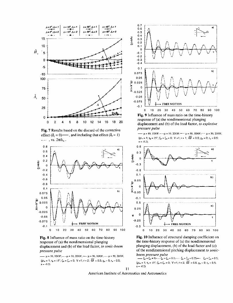
axis are obtained from the aerodynamics of sweptwings (see Yatesl°).The maximum influence of the corrective term
(identified by the tracer _r ) is present the first plunging
coefficients Ht where the aerodynamic coefficient
changes also its sign. Usually, for all coefficients, the
effect of these terms becomes higher for high sweepangles.
For swept wings, the local lift-curve slope CL,,, for
sections normal to the elastic axis are expressed as:
CL_" = Co,_/cos A. (49)
The variation of the unsteady aerodynamic derivatives
/ti and /]_ as a function of k, are depicted. In these
developments, all the terms, including the aerodynamic
ones associated with h and 6_, usually neglected, have
been retained. As a result, the coefficients Hs, H 6 and
A_,A 6 are also included. Whereas the aerodynamic
coefficients /4j and /]2 are the principal uncoupled
aerodynamic damping coefficients in plunging and
torsion, respectively, /-)2 and /]_ are the coupled
damping coefficients. For straight wings, these terms
remains negative for all values of 2folk, and for
different values of aN, but for swept wings only /]2
continues to remain negative. The elastic axis positionis not involved in the expression of the unsteady
aerodynamic coefficients /-)_ and /-)4, a fact, which
clearly appears from the equations. The variation of the
aerodynamic derivatives as a function of k, is, in
general, a smooth one. Among these coefficients, only
/t2 features, with the variation of the reduced
frequency k,, a change of sign. As concerns, the
depiction of /ti and /], versus 2zr/k, (=U,/nbn), this
representation enables one to get an idea of thevariation of the respective quantity with that of the
normal freestream speed U,. The differences in the
unsteady aerodynamic coefficients induced by thediscard or inclusion of the terms generated from thedownwash velocity (i.e. that underscored by a solid linein Eq. (12)) are properly indicated in Figs. 7. As shown,
the corrective term does not modify the trend of
coefficients /]1 and /]4 • It should be mentioned that the
expressions of the lift and aerodynamic moment in the
frequency domain obtained by Barmby, Cunninghamand Garrick I coincide with the ones obtained here via
indicial function approach.
The graphs depicting the aeroelastic response time-history to blast pulses (i.e. explosive and sonic-boom
blasts) are displayed (Figs. 8 - 10). The graphs supply
the dimensionless plunging displacement (4-h/b),
and the load factor (N-h"/g, where g is the
acceleration of gravity). The predictions of _ and N
based on pure plunging and coupled plunging-twist
American Institute of Aeronautics and Astronautics
models are depicted on the same plots, and the
closeness of the two predictions becomes apparent fromthe graphs. Herein, the dotted and solid curvescorrespond to pure plunging and coupled plunging-
pitch models, respectively. As a result, the couplinghelps to reduce the amplitude of the aeroelastic
response. The pitching displacement has its maximumfor "r= 0". The same trend is valid also for the load
factor N. It should be indicated that the response to
sonic-boom pressure pulse involves two different
regimes; one for which 0 < z"< 30" that corresponds to
the forced motion, and the other one to _" > 30"
belonging to the free motion. The jump in the time-
history of N is due to the discontinuity in the load
occurring at z= 30". This jump doesn't appear forexplosive pressure pulses, where r = I. The increase of
the mass ratio results in the increase of the plungingdisplacement amplitude and the decrease of the pitching
amplitude. At the same time, for higher mass ratios, thedifferences in the plunging predictions based upon1DOF and 2 DOF disappear (Figs. 8 and 9). Moreover,for higher mass ratios, the motion damps out at larger
times. Figs. 10 highlights the effect of the structural
damping coefficient in plunging and pftching.Using the idea developed by Yates_U, a modified striptheory can be accommodated as to address the problem
of the aeroelastic response (for open/closed loopaeroelastic systems), by capturing also the 3-D effects.
Alternatively, an exact solution methodology enablingone to determine both the flutter instability and the
aeroelastic dynamic response based on a doubleLaplace transform, in time and space, can be used. Sucha method was devoted to the solution of aeroelastic
eigenvalue problems in Karpouzian & Librescu 5'6,
Librescu & Thangjitham 7. On this basis, the obtained
results can be extended as to approach the subcritical
aeroelastic response and flutter, respectively, of 3-Dadvanced lifting surfaces, in various flight speedregimes.
CONCLUSIONS
A unified treatment of the aeroelasticity of 2-D liftingsurfaces in time and frequency domains has beenpresented and the usefulness in this context of the
aerodynamic indicial functions concept wasemphasized.
Applications assessing the versatility of this approachenabling one to treat both subcritical aeroelastic
responses and flutter instability were presented,and prospects for extending this treatment to 3-Daeroelastic problems are contemplated in forthcomingdevelopments.
ACKNOWLEDGMENT
The first author gratefully acknowledges the support by
by the NASA Langley Research Center through GrantNAG-I-2281 and the Centro Studi per la Dinamica deiFluidi of the Italian National Research Council (CNR).
REFERENCES
1. Barmby, J.G., Cunningham, H.J. & Garrick, I.E.,"Study of Effects of Sweep on the Flutter of
Cantilever Wings." NACA Report No. 1014, 1951.
2. Bisplinghoff, R.L., Ashley, H. & Halfman R.L.,"Aeroelasticity." Dover, ! 955.
3. Edwards, J.W., Ashley, H. & Breakwell, J.V.,"Unsteady Aerodynamic Modeling for Arbitrary
Motions." AIAA Journal, Vol. 17, pp. 365-374,1979, presented as AIAA Paper 77-451 at the AIAA
Dynamics Specialist Conference, San Diego,California, 1977.
4. Flax, A.H., "Aeroelasticity and Flutter, in HighSpeed Problems of Aircraft and ExperimentalMethods." in Vol. VIII "High Speed Aerod_,namics
and Jet Propulsion." Eds. Donovan, H.F. andLawrence, H.R., Princeton University Press, 1961,pp.161-417.
5. Karpouzian, G. & Librescu, L., "Comprehensive
Model of Anisotropic Composite Aircraft WingsSuitable for Aeroelastic Analyses." Journal of
Aircraft, Vol. 31, No. 3, May-June, pp. 703-712,1994.
6. Karpouzian, G. & Librescu, L., "Non-Classical
Effects on Divergence and Flutter of AnisotropicSwept Aircraft Wings." AIAA Journal, Vol. 34,
No. 4, April, pp.786-794, 1996.
7. Librescu, L. & Thangjitham, S., "AnalyticalStudies on Static Aeroelastic Behavior of Forward
Swept Composite Wing Structures." Journal ofAircraft, Vol. 28, No. 2, pp. 151-157, 1991.
8. Scanlan, R.H., "Aeroelastic Problems of Civil
Engineering Structures." in "A Modern Course inAeroelasticit3,." Dowell, E.H. editor, Kluwer
Academic Publishers, Third Revised and EnlargedEdition, 1996.
9. Simiu, E. & Scanlan, R.H., "Wind Effects onStructures." in "An httroduction to Wind
Engineering." 2ndEd., Wiley, NY, 1986.10. Yates, C., "Calculation of Flutter Characteristics
for Finite-Span Swept or Unswept Wings atSubsonic and Supersonic Speeds by a ModifiedStrip Analysis." NACA RM No. L57LI0, March1958.
9
American Institute of Aeronautics and Astronautics
I
0.8
0.6
0.4
0.2
0
-0 .2
-0 .4
-0 ,6
t
0.8
0.6
0.4
0.2
0
-0 .2
-0 .4
-0 .6
Actual root
"7-..SI--/Jt,,,"../. Eff 2 ., e,,o
I
Fig. 1 Nonuniform Swept Wing
1
0.8
0.6
0.4
0.2
0
c,, = 2b.
Fig. 2 Airfoil Section
1 i i i i
0 0.2 0.4 0.6 0.8 17 1
Fig. 3 Bending-Mode and Torsion-Mode
fi2
AZ
20
16
12
8
4
0
-4
0
-5
-10
-15
-20
-25
-30
o8 i4 i
a. i
,l .... I .... I .... I .... I .... I .... I
an
0 2 4 6 8 10 12 14 16 18 20
Fig. 5 Unsteady aerodynamic derivative for sweptlifting surfaces (A = 45 °) and different elastic axis
position (a,0, vs. 2rJk.
A,
0
-10
-20
-30
-40
-50
-60
-70
60
50
40
30
2O
10
0
Fig. 6 Unsteady aerodynamic derivative for swept
Fig. 4 (a) Sonic-Boom and lifting surfaces (A = 15°) and different elastic axis
(b) Triangular Blast Pressure Pulses position (an), vs. 2rdk,10
American Institute of Aeronautics and Astronautics
_"_2
A _r= I
A:_:,-o115
10
5
0
-5
-10
A;;,_t.o ,-_):,.o A_-,_.,,oo..>.
A2
100
75
5O
25
0 _ - _ , • .... , , ", .... i '''', .... ,
0 2 4 6 8 10 12 14 16 18 20
Fig. 7 Results based on the discard of the corrective
effect (Sr = 0)--, and including that effect (St = !)
, vs. 2n/k..
0.8
0.6
0.4
0.2
0
-0.2
-0.4
-0.6
-0.8
0.1
,--. a) i
WV,_, // ',_/./ \%'#" "_" \_'- "'-T_iv' k/l " - i
i
0.075
0.05
_ 0.025
_ 0
-0.025
-0.05
-0.075
-0.1
" V'u <'Zi iJ '..,"i "I
!Y ..I--F,,,,,,,,,o.,-,o,,,0 10 20 30 40 50 60 70 80 90 100
I.LLU_
0.7
0.6
0.5
0.4
0.3
0.2
0.1
0
-0.1
-0.2
-0.3
-0.4
.....;;{...........................................................................................
...t iaU ;iv/ !_ _ i k-'T \_ \ I \i _"dk":f, tt _' 'xd _d v "-' ' i"_/ \d _/ -" /
J0.1
0.075
0.05
._ 0.025
tt 0
:_ -0.025
-0.05
-0.075
-0.1
0
-0.3
-0.6
0.1
0.05
•e 0
_:-0.05
-0.1
0 10 20 30 40 50 60 70 80 90 100
Fig. 9 Influence of mass ratio on the time-history
response of (a) the nondimensional plunging
displacement and (b) of the load factor, to explosive
pressure pulse
It= I0, 1DOF;---It = 10, 2DOF;_-. IX = 50, IDOF; ..... la = 50, 2DOF,
(_Trn= 1;'r.p= 15"; _h= _t_=0; V=l;r= 1; 6.0 =0.5;Z_,= 0; r,,=0.5;
a = -0.2).
0.6
....... _ _ _ ,
0.5
0.25
0
-0.25
-0.5
0 10 20 30 40 50 60 70 80 90 100
Fig. 8 Influence of mass ratio on the time-history
response of (a) the nondimensional plunging
displacement and (b) of the load factor, to sonic-boom
pressure pulse
11 = 10, IDOF; ---it = 10, 2DOF; _- it = 50, 1DOF; ..... it = 50, 2DOF,
(p,_= 1;%= 15";_h=_=0; V=l;r=2; O) = 0.5;Z,,=0; r==0.5;
a = -0.2).
11
Fig. 10 Influence of structural damping coefficient on
the time-history response of (a) the nondimensional
plunging displacement, (b) of the load factor and (c)
of the nondimensional pitching displacement to sonic-
boom pressure pulse
--_,=_=0;-.- _,=_=o.1; ...... _=_,=0.25:--- _=_=05;
(pm=l;rg=lS";_h=_,_=0; V=l;r=2; 0.) =0.5;_,_=0;r_,=0.5;a = -0.2).
American Institute of Aeronautics and Astronautics


![Aerodynamic and Static Aeroelastic Analysis of a Transonic ...iieng.org/images/proceedings_pdf/8773E1214053.pdfastronautics. HUNS3D flow solver [6], [7] designed for both 2D and 3D](https://img.pdfslide.us/doc/110x75/5f85984f6a43ca5909311125/aerodynamic-and-static-aeroelastic-analysis-of-a-transonic-iiengorgimagesproceedingspdf.jpg)