Embed Size (px)
Citation preview
Copyright ⓒ The Korean Society for Aeronautical & Space SciencesReceived: February 6, 2015 Revised: November 15, 2015 Accepted: : January 14, 2016
132 http://ijass.org pISSN: 2093-274x eISSN: 2093-2480
PaperInt’l J. of Aeronautical & Space Sci. 17(1), 132–138 (2016)DOI: http://dx.doi.org/10.5139/IJASS.2016.17.1.132
Aerodynamic Design of the Solar-Powered High Altitude Long Endurance (HALE) Unmanned Aerial Vehicle (UAV)
Seung-Jae Hwang*, Sang-Gon Kim**, Cheol-Won Kim** and Yung-Gyo Lee**Aerodynamic Division, Korea Aerospace Research Institute, Daejeon 34133, Republic of Korea
Abstract
Korea Aerospace Research Institute (KARI) is developing an electric-driven HALE UAV in order to secure system and
operational technologies since 2010. Based on the flight tests and design experiences of the previously developed electric-
driven UAVs, KARI has designed EAV-3, a solar-powered HALE UAV. EAV-3 weighs 53kg, the structure weight is 22kg, and
features a flexible wing of 19.5m in span with the aspect ratio of 17.4. Designing the main wing and empennage of the EAV-
3 the amount of the bending due to the flexible wing, 404mm at 1-G flight condition based on T-800 composite material, and
side wind effects due to low cruise speed, Vcr = 6m/sec, are carefully considered. Also, unlike the general aircraft there is no
center of gravity shift during the flight because of the EAV-3 is the solar-electric driven UAV. Thus, static margin cuts down
to 28.4% and center of gravity moves back to 31% of the Mean Aerodynamic Chord (MAC) comparing with the previously
designed the EAV-2 and EAV-2H/2H+ to upgrade the flight performance of the EAV-3.
Key words: HALE, UAV, Solar-powered, Flexible wing, Ultra-light weight
Nomenclature
AR = Aspect ratio, ~
bw = Wing span, m
CD = Drag coefficient of aircraft, ~
CDi = Induced drag Coefficient of aircraft, ~
CL = Lift coefficient of aircraft, ~
Clp = Airplane rolling moment coefficient with change of
roll rate, rad-1
Clr = Airplane rolling moment coefficient with change of
yaw rate, rad-1
Clβ = Airplane rolling moment coefficient with angle of
sideslip, rad-1
Clδr = Airplane rolling moment coefficient with rudder
deflection angle, rad-1
Cm = Pitching moment coefficient of aircraft, ~
Cm0 = Pitching moment coefficient of aircraft for zero angle
of attack, ~
Cmα = Pitching moment coefficient of aircraft with angle of
attack, rad-1
Aerodynamic Design of the Solar-Powered High Altitude
Long Endurance (HALE) Unmanned Aerial Vehicle (UAV)
Seung-Jae Hwang*, Sang-Gon Kim**, Cheol-Won Kim** and Yung-Gyo Lee**Aerodynamic Division, Korea Aerospace Research Institute, Daejeon 34133, Republic of Korea
Abstract
Korea Aerospace Research Institute (KARI) is developing an electric-driven HALE UAV in order to secure
system and operational technologies since 2010. Based on the flight tests and design experiences of the
previously developed electric-driven UAVs, KARI has designed EAV-3, a solar-powered HALE UAV. EAV-3
weighs 53kg, the structure weight is 22kg, and features a flexible wing of 19.5m in span with the aspect ratio
of 17.4. Designing the main wing and empennage of the EAV-3 the amount of the bending due to the flexible
wing, 404mm at 1-G flight condition based on T-800 composite material, and side wind effects due to low
cruise speed, 𝑉𝑉𝑐𝑐𝑐𝑐 = 6m/sec, are carefully considered. Also, unlike the general aircraft there is no center of
gravity shift during the flight because of the EAV-3 is the solar-electric driven UAV. Thus, static margin cuts
down to 28.4% and center of gravity moves back to 31% of the Mean Aerodynamic Chord (MAC) comparing
with the previously designed the EAV-2 and EAV-2H/2H+ to upgrade the flight performance of the EAV-3.
Key Words: HALE, UAV, Solar-powered, Flexible wing, Ultra-light weight
Nomenclature
AR = Aspect ratio, ~
𝑏𝑏𝑤𝑤 = Wing span, m
𝐶𝐶𝐷𝐷 = Drag coefficient of aircraft, ~
𝐶𝐶𝐷𝐷𝑖𝑖 = Induced drag Coefficient of aircraft, ~
𝐶𝐶𝐿𝐿 = Lift coefficient of aircraft, ~
𝐶𝐶𝑙𝑙𝑝𝑝 = Airplane rolling moment coefficient
with change of roll rate, 𝑟𝑟𝑟𝑟𝑟𝑟−1 𝐶𝐶𝑙𝑙𝑟𝑟 = Airplane rolling moment coefficient
with change of yaw rate, 𝑟𝑟𝑟𝑟𝑟𝑟−1
𝐶𝐶𝑙𝑙𝛽𝛽 = Airplane rolling moment coefficient
with angle of sideslip, 𝑟𝑟𝑟𝑟𝑟𝑟−1 𝐶𝐶𝑙𝑙𝛿𝛿𝑟𝑟 = Airplane rolling moment coefficient
with rudder deflection angle, 𝑟𝑟𝑟𝑟𝑟𝑟−1
𝐶𝐶𝑚𝑚 = Pitching moment coefficient of aircraft,
~
𝐶𝐶𝑚𝑚0 = Pitching moment coefficient of aircraft
for zero angle of attack, ~
𝐶𝐶𝑚𝑚𝛼𝛼 = Pitching moment coefficient of aircraft
with angle of attack, 𝑟𝑟𝑟𝑟𝑟𝑟−1 𝐶𝐶𝑚𝑚�̇�𝛼 = Pitching moment coefficient of aircraft
with change of angle of attack, 𝑟𝑟𝑟𝑟𝑟𝑟−1 𝐶𝐶𝑚𝑚𝑞𝑞 = Pitching moment coefficient of aircraft
with pitch rate, 𝑟𝑟𝑟𝑟𝑟𝑟−1 𝐶𝐶𝑚𝑚𝛿𝛿𝛿𝛿 = Pitching moment coefficient of aircraft
with elevator deflection angle, 𝑟𝑟𝑟𝑟𝑟𝑟−1 𝐶𝐶𝑛𝑛𝑝𝑝 = Airplane yawing moment coefficient
with change of roll rate, 𝑟𝑟𝑟𝑟𝑟𝑟−1 𝐶𝐶𝑛𝑛𝑟𝑟 = Airplane yawing moment coefficient
with change of yaw rate, 𝑟𝑟𝑟𝑟𝑟𝑟−1 𝐶𝐶𝑛𝑛𝛽𝛽 = Airplane yawing moment coefficient
with angle of sideslip, 𝑟𝑟𝑟𝑟𝑟𝑟−1 𝐶𝐶𝑛𝑛𝛿𝛿𝑟𝑟 = Airplane yawing moment coefficient
with rudder deflection angle, 𝑟𝑟𝑟𝑟𝑟𝑟−1 𝐶𝐶𝑦𝑦𝑝𝑝 = Airplane side force coefficient with
change of roll rate, 𝑟𝑟𝑟𝑟𝑟𝑟−1 𝐶𝐶𝑦𝑦𝑟𝑟 = Airplane side force coefficient with
change of yaw rate, 𝑟𝑟𝑟𝑟𝑟𝑟−1 𝐶𝐶𝑦𝑦𝛽𝛽 = Airplane side force coefficient with
* Senior Researcher, Corresponding author: [email protected]
** Researcher, [email protected]
** Principal Researcher, [email protected] Received: February 6, 2015 Revised: November 15, 2015 Accepted: : January 14, 2016
= Pitching moment coefficient of aircraft with change
of angle of attack, rad-1
Cmq = Pitching moment coefficient of aircraft with pitch
rate, rad-1
Cmδe = Pitching moment coefficient of aircraft with elevator
deflection angle, rad-1
Cnp = Airplane yawing moment coefficient with change of
roll rate, rad-1
Cnr = Airplane yawing moment coefficient with change of
yaw rate, rad-1
Cnβ = Airplane yawing moment coefficient with angle of
sideslip, rad-1
Cnδr = Airplane yawing moment coefficient with rudder
deflection angle, rad-1
Cyp = Airplane side force coefficient with change of roll
rate, rad-1
Cyr = Airplane side force coefficient with change of yaw
rate, rad-1
Cyβ = Airplane side force coefficient with angle of sideslip,
This is an Open Access article distributed under the terms of the Creative Com-mons Attribution Non-Commercial License (http://creativecommons.org/licenses/by-nc/3.0/) which permits unrestricted non-commercial use, distribution, and reproduc-tion in any medium, provided the original work is properly cited.
* Senior Researcher, Corresponding author: [email protected] ** Researcher, [email protected] *** Principal Researcher, [email protected]
(132~138)15-152.indd 132 2016-03-29 오후 7:28:44

133
Seung-Jae Hwang Aerodynamic Design of the Solar-Powered High Altitude Long Endurance (HALE) Unmanned Aerial ...
http://ijass.org
rad-1
Cyδr = Airplane side force coefficient with rudder
deflection angle, rad-1
Cw = Mean wing chord length, m
D = Drag force, N
e = Oswald’s efficiency factor, ~
L = Lift force, N
P = Power, watt
Re = Reynolds number, ~
Sh = Horizontal tail area, m2
Sv = Vertical tail area, m2
Sw = Wing area, m2
T = Thrust force, N
V = Velocity, m/sec
V1 = Side wind velocity, m/sec
Vcr = Cruise speed, m/sec
VV = Vertical tail volume coefficient, ~
Vh = Horizontal tail volume coefficient, ~
W = Airplane weight, N
XC.G = Location of center of gravity, m
Xach = Location of horizontal tail aerodynamic center, m
Xacv = Location of vertical tail aerodynamic center, m
y+ = Non-dimensional wall distance, ~
α = Angle of attack, degree
β = Angle of sideslip, degree
ρ = Density of air, kg/m3
δe = Elevator deflection angle, degree
η = Solar cell energy conversion efficiency, ~
SOC = State of charge, %
ROC = Rate of climb, m/sec
1. Introduction
Since Qinetiq’s Zephyr 7 (Maximum Takeoff Weight
53kg, a wing span 22.5m) has successfully flown in the
stratosphere, maximum Climb Altitude 21.562km, for two
weeks, 336 hours July9~23 2010 [1], High Altitude Long
Endurance (HALE) Unmanned Aerial Vehicles (UAVs) are
globally developing to substitute a low earth orbit satellite.
HALE UAVs that are recyclable and convenient to use are
targeting to stay in the stratosphere more than 5 years to
compete with the satellite. In the recent years Google and
Facebook take over Titan Aerospace and Ascenta to develop
an electric-driven HALE UAV that can provide an internet
service to Africa to create a new market for them. Following
the global trends Korea Aerospace Research Institute (KARI)
is also developing an electric-driven HALE UAV since 2010.
Electrical Aerial Vehicle (EAV)-1 powered by fuel cell and
lithium-polymer battery has developed and completed flight
tests in 2011 [2, 3]. EAV-2, which is a concept demonstrator
of the hybrid power system with a fuel cell, solar cell and
battery, has developed and a first flight test has performed
on December 2011. EAV-2 has successfully flown 22 hours in
2012 and climbed up to 5km in 2013. EAV-2H, which is a scale
downed version of the EAV-3, powered by an amorphous
silicon solar cell and lithium-ion battery has developed and
a first flight test has performed on October 2012 [4, 5]. EAV-
2H has continuously flown 25.7 hours in 2013. Also, modified
version of the EAV-2H, EAV-2H+, has successfully climbed
up to an altitude 10km in 2014. KARI’s developed EAV series
are presented in Fig. 1.
In order to secure system and operational technologies
and reduce to risk of the failure of developing a full scale
solar-powered HALE UAV, the scale-downed version of the
EAV-3, EAV-2H/2H+, has developed first and performed
flight tests to verify the conceptual design. Based on the
design of EAV-2H/2H+, EAV-3 is developed to verify a
climb ability up to an altitude 20km and to demonstrate the
developed system’s stability and operational feasibility in the
severe environment of the stratosphere.
2. Solar-Powered HALE UAV
2.1 History of development of HALE UAV in KARI
KARI has developed the EAV-1, a wing span is 2.4m
and total take-off weight is 6.8kg, to secure system and
operational technologies for the electric aircraft [3]. Based
on the CFD analysis and flight tests of the EAV-1, the mid-
size low drag electrical long endurance UAV, EAV-2, has
developed. The wing span, wing area, total take-off weight
and empty weight of the EAV-2 are 6.93m, 2.09m2, 18kg and
11kg, respectably. In order to reduce the total drag of the
EAV-2, an aspect ratio (AR) is increased from 8.5 to 20 and
a low drag fuselage design and raked wingtip are applied.
The total drag in the level flight of the EAV-2 are reduced
with angle of sideslip, 𝑟𝑟𝑟𝑟𝑟𝑟−1 𝐶𝐶𝑦𝑦𝛿𝛿𝛿𝛿 = Airplane side force coefficient with
rudder deflection angle, 𝑟𝑟𝑟𝑟𝑟𝑟−1 𝐶𝐶𝑤𝑤 = Mean wing chord length, m
D = Drag force, N
e = Oswald’s efficiency factor, ~
L = Lift force, N
P = Power, watt
Re = Reynolds number, ~
𝑆𝑆ℎ = Horizontal tail area, m2
𝑆𝑆𝑣𝑣 = Vertical tail area, m2
𝑆𝑆𝑤𝑤 = Wing area, m2
T = Thrust force, N
V = Velocity, m/sec
𝑉𝑉1 = Side wind velocity, m/sec
𝑉𝑉𝑐𝑐𝑐𝑐 = Cruise speed, m/sec
𝑉𝑉𝑉𝑉 = Vertical tail volume coefficient, ~
𝑉𝑉ℎ = Horizontal tail volume coefficient, ~
W = Airplane weight, N
𝑋𝑋𝐶𝐶.𝐺𝐺 = Location of center of gravity, m
𝑋𝑋𝑎𝑎𝑐𝑐ℎ = Location of horizontal tail aerodynamic
center, m
𝑋𝑋𝑎𝑎𝑐𝑐𝑣𝑣 = Location of vertical tail aerodynamic
center, m
y+ = Non-dimensional wall distance, ~
α = Angle of attack, degree
β = Angle of sideslip, degree
ρ = Density of air, kg/m3
𝛿𝛿𝑒𝑒 = Elevator deflection angle, degree
η = Solar cell energy conversion
efficiency, ~
SOC = State of charge, %
ROC = Rate of climb, m/sec
1. Introduction
Since Qinetiq’s Zephyr 7 (Maximum
Takeoff Weight 53kg, a wing span 22.5m) has
successfully flown in the stratosphere, maximum
Climb Altitude 21.562km, for two weeks, 336
hours July9~23 2010 [1], High Altitude Long
Endurance (HALE) Unmanned Aerial Vehicles
(UAVs) are globally developing to substitute a
low earth orbit satellite. HALE UAVs that are
recyclable and convenient to use are targeting to
stay in the stratosphere more than 5 years to
compete with the satellite. In the recent years
Google and Facebook take over Titan Aerospace
and Ascenta to develop an electric-driven
HALE UAV that can provide an internet service
to Africa to create a new market for them.
Following the global trends Korea Aerospace
Research Institute (KARI) is also developing an
electric-driven HALE UAV since 2010.
Electrical Aerial Vehicle (EAV)-1 powered by
fuel cell and lithium-polymer battery has
developed and completed flight tests in 2011 [2,
3]. EAV-2, which is a concept demonstrator of
the hybrid power system with a fuel cell, solar
cell and battery, has developed and a first flight
test has performed on December 2011. EAV-2
has successfully flown 22 hours in 2012 and
climbed up to 5km in 2013. EAV-2H, which is a
scale downed version of the EAV-3, powered
by an amorphous silicon solar cell and lithium-
ion battery has developed and a first flight test
has performed on October 2012 [4, 5]. EAV-2H
has continuously flown 25.7 hours in 2013. Also,
modified version of the EAV-2H, EAV-2H+,
has successfully climbed up to an altitude 10km
in 2014. KARI’s developed EAV series are
presented in Fig. 1.
In order to secure system and operational
technologies and reduce to risk of the failure of
developing a full scale solar-powered HALE UAV, the
scale-downed version of the EAV-3, EAV-2H/2H+,
has developed first and performed flight tests to verify
the conceptual design. Based on the design of EAV-
2H/2H+, EAV-3 is developed to verify a climb ability
up to an altitude 20km and to demonstrate the
developed system’s stability and operational feasibility
in the severe environment of the stratosphere.
(a) EAV-1 (b) EAV-2
(c) EAV-2H (d) EAV-2H+
Fig. 1. Electric Aerial Vehicle (EAV) Series.
2. Solar-Powered HALE UAV
2.1 History of development of HALE UAV in KARI
(a) EAV-1 (b) EAV-2
with angle of sideslip, 𝑟𝑟𝑟𝑟𝑟𝑟−1 𝐶𝐶𝑦𝑦𝛿𝛿𝛿𝛿 = Airplane side force coefficient with
rudder deflection angle, 𝑟𝑟𝑟𝑟𝑟𝑟−1 𝐶𝐶𝑤𝑤 = Mean wing chord length, m
D = Drag force, N
e = Oswald’s efficiency factor, ~
L = Lift force, N
P = Power, watt
Re = Reynolds number, ~
𝑆𝑆ℎ = Horizontal tail area, m2
𝑆𝑆𝑣𝑣 = Vertical tail area, m2
𝑆𝑆𝑤𝑤 = Wing area, m2
T = Thrust force, N
V = Velocity, m/sec
𝑉𝑉1 = Side wind velocity, m/sec
𝑉𝑉𝑐𝑐𝑐𝑐 = Cruise speed, m/sec
𝑉𝑉𝑉𝑉 = Vertical tail volume coefficient, ~
𝑉𝑉ℎ = Horizontal tail volume coefficient, ~
W = Airplane weight, N
𝑋𝑋𝐶𝐶.𝐺𝐺 = Location of center of gravity, m
𝑋𝑋𝑎𝑎𝑐𝑐ℎ = Location of horizontal tail aerodynamic
center, m
𝑋𝑋𝑎𝑎𝑐𝑐𝑣𝑣 = Location of vertical tail aerodynamic
center, m
y+ = Non-dimensional wall distance, ~
α = Angle of attack, degree
β = Angle of sideslip, degree
ρ = Density of air, kg/m3
𝛿𝛿𝑒𝑒 = Elevator deflection angle, degree
η = Solar cell energy conversion
efficiency, ~
SOC = State of charge, %
ROC = Rate of climb, m/sec
1. Introduction
Since Qinetiq’s Zephyr 7 (Maximum
Takeoff Weight 53kg, a wing span 22.5m) has
successfully flown in the stratosphere, maximum
Climb Altitude 21.562km, for two weeks, 336
hours July9~23 2010 [1], High Altitude Long
Endurance (HALE) Unmanned Aerial Vehicles
(UAVs) are globally developing to substitute a
low earth orbit satellite. HALE UAVs that are
recyclable and convenient to use are targeting to
stay in the stratosphere more than 5 years to
compete with the satellite. In the recent years
Google and Facebook take over Titan Aerospace
and Ascenta to develop an electric-driven
HALE UAV that can provide an internet service
to Africa to create a new market for them.
Following the global trends Korea Aerospace
Research Institute (KARI) is also developing an
electric-driven HALE UAV since 2010.
Electrical Aerial Vehicle (EAV)-1 powered by
fuel cell and lithium-polymer battery has
developed and completed flight tests in 2011 [2,
3]. EAV-2, which is a concept demonstrator of
the hybrid power system with a fuel cell, solar
cell and battery, has developed and a first flight
test has performed on December 2011. EAV-2
has successfully flown 22 hours in 2012 and
climbed up to 5km in 2013. EAV-2H, which is a
scale downed version of the EAV-3, powered
by an amorphous silicon solar cell and lithium-
ion battery has developed and a first flight test
has performed on October 2012 [4, 5]. EAV-2H
has continuously flown 25.7 hours in 2013. Also,
modified version of the EAV-2H, EAV-2H+,
has successfully climbed up to an altitude 10km
in 2014. KARI’s developed EAV series are
presented in Fig. 1.
In order to secure system and operational
technologies and reduce to risk of the failure of
developing a full scale solar-powered HALE UAV, the
scale-downed version of the EAV-3, EAV-2H/2H+,
has developed first and performed flight tests to verify
the conceptual design. Based on the design of EAV-
2H/2H+, EAV-3 is developed to verify a climb ability
up to an altitude 20km and to demonstrate the
developed system’s stability and operational feasibility
in the severe environment of the stratosphere.
(a) EAV-1 (b) EAV-2
(c) EAV-2H (d) EAV-2H+
Fig. 1. Electric Aerial Vehicle (EAV) Series.
2. Solar-Powered HALE UAV
2.1 History of development of HALE UAV in KARI
(c) EAV-2H (d) EAV-2H+
Fig. 1. Electric Aerial Vehicle (EAV) Series.
(132~138)15-152.indd 133 2016-03-29 오후 7:28:45

DOI: http://dx.doi.org/10.5139/IJASS.2016.17.1.132 134
Int’l J. of Aeronautical & Space Sci. 17(1), 132–138 (2016)
35% comparing with the EAV-1 [4, 5]. After that, the solar-
powered scaled HALE UAV, EAV-2H, has developed. The
EAV-2H is the scaled-up version of the EAV-2, but an
ultra-light weight structural design skill is employed. Even
though the wing span (10.83m) and wing area (5.09m2)
of the EAV-2H are increased 56% and 144% comparing
to the EAV-2, an empty weight (11kg) of the two aircraft
is stayed same and a total weight of the EAV-2H (20kg) is
only 2kg heavier than the EAV-2. The structural weight vs.
wing loading of the EAV-2, EAV-2H and EAV-3 are plotted
in Fig. 2.
Electric motor of the EAV-2H is driven by amorphous
solar cells on the main wing and Li-Ion secondary
batteries. A SG6043 airfoil that has good aerodynamic
characteristics in a low Reynolds number flow (Re ~ 2.0
x 105) is selected for the main wing and NACA 0010 and
NACA 0012 are selected for the horizontal and vertical tail,
respectably. The volume coefficients of the horizontal and
vertical tail are 0.57 and 0.028, initially [3, 5]. However,
after a couple of test flights of the EAV-2H, the vertical tail
volume coefficient is reduce to 0.024 to minimize a side
force due to the side wind (V1) and secure a directional
stability at the least, sideslip angle (β) = 25° degree and V1
= 3.54m/sec. The size of the vertical tail is reduced 15%
to cut down 15% of the variation of airplane side force
coefficient with sideslip angle, Cyβ, and 22% of the variation
of airplane side force coefficient with dimensionless rate
of change of yaw rate, Cyr. Also, the vertical tail to rudder
ratio, Cr/Cv, is increased from 30% to 60% to secure the
directional stability at the least, the variation of airplane
yawing moment coefficient with angle of sideslip (Cnβ) =
0.0588rad-1 [6, 7].
Based on the design experiences and flight tests of the
EAV-1, EAV-2 and EAV-2H/H+, KARI’s solar-powered HALE
UAV, EAV-3, has designed.
2.2 EAV-3 Design Requirements
The solar-powered HALE UAV, EAV-3, design requirements
are as follows:
1. Maximum take-off weight is less than 53kg. (Structure
weight is 22kg, weight of Li-Ion batteries is 13kg and
weight of on-board system is 18kg).
2. Be able to climb above an altitude 18km (Stratosphere
flight, Temperature below -70° C).
3. Minimum energy speed in the level flight is 6m/sec
and maximum speed in the level flight is less than
10m/sec in the sea level that allows the EAV-3 is able to
operate and pass through a jet stream less than 15m/sec
between the altitude 8~12km.
2.3 EAV-3 Power Requirements
Required total power of the EAV-3 is calculated based on
a mission profile for the stratosphere flight up to the altitude
18km. A developing purpose of the EAV-3 is obtaining system
and operational technologies for the electric driven HALE
KARI has developed the EAV-1, a wing
span is 2.4m and total take-off weight is 6.8kg,
to secure system and operational technologies
for the electric aircraft [3]. Based on the CFD
analysis and flight tests of the EAV-1, the mid-
size low drag electrical long endurance UAV,
EAV-2, has developed. The wing span, wing
area, total take-off weight and empty weight of
the EAV-2 are 6.93m, 2.09m2, 18kg and 11kg,
respectably. In order to reduce the total drag of
the EAV-2, an aspect ratio (AR) is increased
from 8.5 to 20 and a low drag fuselage design
and raked wingtip are applied. The total drag in
the level flight of the EAV-2 are reduced 35%
comparing with the EAV-1 [4, 5]. After that,
the solar-powered scaled HALE UAV, EAV-2H,
has developed. The EAV-2H is the scaled-up
version of the EAV-2, but an ultra-light weight
structural design skill is employed. Even though
the wing span (10.83m) and wing area (5.09m2)
of the EAV-2H are increased 56% and 144%
comparing to the EAV-2, an empty weight
(11kg) of the two aircraft is stayed same and a
total weight of the EAV-2H (20kg) is only 2kg
heavier than the EAV-2. The structural weight
vs. wing loading of the EAV-2, EAV-2H and
EAV-3 are plotted in Fig. 2.
Electric motor of the EAV-2H is driven
by amorphous solar cells on the main wing and
Li-Ion secondary batteries. A SG6043 airfoil
that has good aerodynamic characteristics in a
low Reynolds number flow (Re ~ 2.0 x 10⁵) is
selected for the main wing and NACA 0010 and
NACA 0012 are selected for the horizontal and
vertical tail, respectably. The volume
coefficients of the horizontal and vertical tail are
0.57 and 0.028, initially [3, 5]. However, after a
couple of test flights of the EAV-2H, the
vertical tail volume coefficient is reduce to
0.024 to minimize a side force due to the side
wind (𝑉𝑉1) and secure a directional stability at the
least, sideslip angle (β) = 25° degree and 𝑉𝑉1 =
3.54m/sec. The size of the vertical tail is
reduced 15% to cut down 15% of the variation
of airplane side force coefficient with sideslip
angle, 𝐶𝐶𝑦𝑦𝛽𝛽, and 22% of the variation of airplane
side force coefficient with dimensionless rate of
change of yaw rate, 𝐶𝐶𝑦𝑦𝑟𝑟. Also, the vertical tail to
rudder ratio, Cr/Cv, is increased from 30% to 60%
to secure the directional stability at the least,
the variation of airplane yawing moment
coefficient with angle of sideslip ( 𝐶𝐶𝑛𝑛𝛽𝛽 ) =
0.0588rad-1 [6, 7].
Based on the design experiences and
flight tests of the EAV-1, EAV-2 and EAV-
2H/H+, KARI’s solar-powered HALE UAV,
EAV-3, has designed.
Fig. 2. Structural Weight Comparison of the
Electric Aerial Vehicle (EAV) Series.
2.2 EAV-3 Design Requirements
The solar-powered HALE UAV, EAV-3,
design requirements are as follows:
1. Maximum take-off weight is less than
53kg. (Structure weight is 22kg,
weight of Li-Ion batteries is 13kg and
weight of on-board system is 18kg).
2. Be able to climb above an altitude
18km (Stratosphere flight,
Temperature below -70° C).
3. Minimum energy speed in the level
flight is 6m/sec and maximum speed
in the level flight is less than 10m/sec
in the sea level that allows the EAV-3
is able to operate and pass through a
jet stream less than 15m/sec between
the altitude 8~12km.
2.3 EAV-3 Power Requirements
Required total power of the EAV-3 is
calculated based on a mission profile for the
Fig. 2. Structural Weight Comparison of the Electric Aerial Vehicle (EAV) Series.
stratosphere flight up to the altitude 18km. A
developing purpose of the EAV-3 is obtaining
system and operational technologies for the
electric driven HALE UAV. Thus, the main focus
is aimed to the climb ability up to the altitude
18km and operate temperature below -70°C in
the challenged stratosphere environment. The
EAV-3 mission profile is presented in Fig. 3.
Also, the EAV-3 climb trajectory up to the
altitude 18km is calculated based on the summer
jet stream conditions (less than 15 m/sec) in the
Goheung, South Korea. The projected radius of
the flight path is 20km. The calculated EAV-3
trajectory is presented in Fig. 4.
Three modules of the mono-crystalline
solar cells are attached on the wing of the EAV-
3. The solar cell energy conversion efficiency
(η) is 23% and the manufactured module
efficiency is 21% that generates more than
1.5kWh of energy during the flight. Also, four
energy density of 230Wh/kg Li-Ion battery
packs are loaded in the EAV-3 that weigh 13kg
total and carry 3kWh of energy. The climb time,
total power requirement, battery SOC and
expected solar power from the solar cells with
the rates of climb (ROC) are presented in Fig. 5.
Fig. 3. EAV-3 Mission Profile.
Fig. 4. EAV-3 Calculated Climb Trajectory
(Goheung, South Korea in Summer time)
Fig. 5. EAV-3 Climb Time and Power.
2.4 EAV-3 Main Wing Design
The biggest practical limitation of
designing the solar-powered HALE UAV is a
wing area should be maximized to install the
solar panels on the main wing. 490 SunPower
Fig. 3. EAV-3 Mission Profile.
stratosphere flight up to the altitude 18km. A
developing purpose of the EAV-3 is obtaining
system and operational technologies for the
electric driven HALE UAV. Thus, the main focus
is aimed to the climb ability up to the altitude
18km and operate temperature below -70°C in
the challenged stratosphere environment. The
EAV-3 mission profile is presented in Fig. 3.
Also, the EAV-3 climb trajectory up to the
altitude 18km is calculated based on the summer
jet stream conditions (less than 15 m/sec) in the
Goheung, South Korea. The projected radius of
the flight path is 20km. The calculated EAV-3
trajectory is presented in Fig. 4.
Three modules of the mono-crystalline
solar cells are attached on the wing of the EAV-
3. The solar cell energy conversion efficiency
(η) is 23% and the manufactured module
efficiency is 21% that generates more than
1.5kWh of energy during the flight. Also, four
energy density of 230Wh/kg Li-Ion battery
packs are loaded in the EAV-3 that weigh 13kg
total and carry 3kWh of energy. The climb time,
total power requirement, battery SOC and
expected solar power from the solar cells with
the rates of climb (ROC) are presented in Fig. 5.
Fig. 3. EAV-3 Mission Profile.
Fig. 4. EAV-3 Calculated Climb Trajectory
(Goheung, South Korea in Summer time)
Fig. 5. EAV-3 Climb Time and Power.
2.4 EAV-3 Main Wing Design
The biggest practical limitation of
designing the solar-powered HALE UAV is a
wing area should be maximized to install the
solar panels on the main wing. 490 SunPower
Fig. 4. EAV-3 Calculated Climb Trajectory (Goheung, South Korea in Summer time)
(132~138)15-152.indd 134 2016-03-29 오후 7:28:46

135
Seung-Jae Hwang Aerodynamic Design of the Solar-Powered High Altitude Long Endurance (HALE) Unmanned Aerial ...
http://ijass.org
UAV. Thus, the main focus is aimed to the climb ability up to
the altitude 18km and operate temperature below -70°C in
the challenged stratosphere environment. The EAV-3 mission
profile is presented in Fig. 3. Also, the EAV-3 climb trajectory
up to the altitude 18km is calculated based on the summer
jet stream conditions (less than 15 m/sec) in the Goheung,
South Korea. The projected radius of the flight path is 20km.
The calculated EAV-3 trajectory is presented in Fig. 4.
Three modules of the mono-crystalline solar cells are
attached on the wing of the EAV-3. The solar cell energy
conversion efficiency (η) is 23% and the manufactured
module efficiency is 21% that generates more than 1.5kWh
of energy during the flight. Also, four energy density of
230Wh/kg Li-Ion battery packs are loaded in the EAV-3 that
weigh 13kg total and carry 3kWh of energy. The climb time,
total power requirement, battery SOC and expected solar
power from the solar cells with the rates of climb (ROC) are
presented in Fig. 5.
2.4 EAV-3 Main Wing Design
The biggest practical limitation of designing the solar-
powered HALE UAV is a wing area should be maximized
to install the solar panels on the main wing. 490 SunPower
mono-crystalline solar cells are used to make three modules.
Size of the first and third modules is 2470mm x 950mm and
second module is 4100mm x 950mm in width by height. Also,
20% of the leading edge clearance is applied to maintain
a laminar flow and delay a transition point over the wing
when the modules are mounted on the wing. The solar panel
modules mounted on the wing are presented in Fig. 6.
The total available power is 1.5kWh from the solar panels
and 3kWh from the 13kg of Li-Ion secondary batteries. The
minimum energy cruise speed in the level flight is 6m/sec
and a wing root and tip chord is fixed 1300mm and 930mm,
respectably. With these limitations the main wing design of
the EAV-3 is optimized with following equations:
mono-crystalline solar cells are used to make
three modules. Size of the first and third
modules is 2470mm x 950mm and second
module is 4100mm x 950mm in width by height.
Also, 20% of the leading edge clearance is
applied to maintain a laminar flow and delay a
transition point over the wing when the modules
are mounted on the wing. The solar panel
modules mounted on the wing are presented in
Fig. 6.
The total available power is 1.5kWh from
the solar panels and 3kWh from the 13kg of Li-
Ion secondary batteries. The minimum energy
cruise speed in the level flight is 6m/sec and a
wing root and tip chord is fixed 1300mm and
930mm, respectably. With these limitations the
main wing design of the EAV-3 is optimized
with following equations:
L = W = 12
× 𝜌𝜌 × 𝑉𝑉2 × 𝐶𝐶𝐿𝐿 × 𝑆𝑆𝑤𝑤 (1)
D = T = 12
× 𝜌𝜌 × 𝑉𝑉2 × 𝐶𝐶𝐷𝐷 × 𝑆𝑆𝑤𝑤 (2)
P = T × V = 12
× 𝜌𝜌 × 𝑉𝑉3 × 𝐶𝐶𝐷𝐷 × 𝑆𝑆𝑤𝑤 (3)
Maximum take-off weight (W) = 53kg, 𝐶𝐶𝐿𝐿
= 1.0 and 𝐶𝐶𝐷𝐷 = 400 counts in the level flight
conditions are applied to design the EAV-3 as
the same conditions have applied to design the
previous EAV-2 and EAV-2H [4, 5, 6]. The
SG6043 airfoil is consistently maintained for the
main wing airfoil of the EAV-3. However, a 4°
degree of the dihedral angle that has employed
on the main wing of the EAV-2H/H+ has
removed to count on the flexibility of the main
wing of the EAV-3. The calculated amount of
the bending in 1-G flight condition is 404mm
based on the T-800 composite material that has
applied to manufacture the EAV-3. The amount
of bending on the flexible EAV-3 wing has same
effects that 4° degree of the dihedral angle
applied in the rigid wing. These effects are
verified with the Advance Aircraft Analysis
Software Package (AAA) [8].
Effects on the induced drag due to change
of the aspect ratios are numerically investigated
by using the Fluent [9]. The numerical
calculations are carried out with S-A turbulence
model using patankar and spalding simple
algorithm and second order upwind scheme.
Dimensionless wall distance (y+) < 1 is kept and
8~13 million meshes are used. The initial
conditions employed for the CFD analysis are V
= 6m/sec, Re = 5 x 10⁵ and 4° degree of angle
of attack (𝐶𝐶𝐿𝐿 = 1.0). The numerical results are
presented in Table 1.
As the aspect ratio increases from 14.8 to
20, the amount of the drag decreases 12.5% (51
counts). It well matches a general tendency that
as the aspect ratio increases, the induced drag
of the wing decreases and the aerodynamic
performance of the aircraft is enhanced.
However, the EAV-3 has the flexible wing and
ultra-light weight design concept is employed.
As the aspect ratio is increased, the wing span
is enlarged and wing root chord is shorten. As a
result, the center of gravity of the wing moves
toward the wing tip and the amount of the
bending is also increased that degrades the
aerodynamic performance of the wing. To
prevent the adverse effect a stiffness of the
wing has to be increased that results the
structure weight increment and makes to
consume more energy in the flight. Therefore,
the aspect ratio of the EAV-3 is selected 17.4
that satisfies the structure weight restriction of
the 22kg and maximizes the aerodynamic
performance of the EAV-3 at the same time.
Also, the raked-wingtip is applied to reduce the
induced drag of the wing. The raked-wingtip
reduces 3.4% of the drag [10].
The designed EAV-3 wing has the wing
span (b) = 19.5m and wing area ( 𝑆𝑆𝑊𝑊 ) =
21.84m2 with the raked-wingtip and no dihedral
angle. The wing is presented in Fig. 7.
Fig. 6. Solar panels on the wing of EAV-3.
(1)
mono-crystalline solar cells are used to make
three modules. Size of the first and third
modules is 2470mm x 950mm and second
module is 4100mm x 950mm in width by height.
Also, 20% of the leading edge clearance is
applied to maintain a laminar flow and delay a
transition point over the wing when the modules
are mounted on the wing. The solar panel
modules mounted on the wing are presented in
Fig. 6.
The total available power is 1.5kWh from
the solar panels and 3kWh from the 13kg of Li-
Ion secondary batteries. The minimum energy
cruise speed in the level flight is 6m/sec and a
wing root and tip chord is fixed 1300mm and
930mm, respectably. With these limitations the
main wing design of the EAV-3 is optimized
with following equations:
L = W = 12
× 𝜌𝜌 × 𝑉𝑉2 × 𝐶𝐶𝐿𝐿 × 𝑆𝑆𝑤𝑤 (1)
D = T = 12
× 𝜌𝜌 × 𝑉𝑉2 × 𝐶𝐶𝐷𝐷 × 𝑆𝑆𝑤𝑤 (2)
P = T × V = 12
× 𝜌𝜌 × 𝑉𝑉3 × 𝐶𝐶𝐷𝐷 × 𝑆𝑆𝑤𝑤 (3)
Maximum take-off weight (W) = 53kg, 𝐶𝐶𝐿𝐿
= 1.0 and 𝐶𝐶𝐷𝐷 = 400 counts in the level flight
conditions are applied to design the EAV-3 as
the same conditions have applied to design the
previous EAV-2 and EAV-2H [4, 5, 6]. The
SG6043 airfoil is consistently maintained for the
main wing airfoil of the EAV-3. However, a 4°
degree of the dihedral angle that has employed
on the main wing of the EAV-2H/H+ has
removed to count on the flexibility of the main
wing of the EAV-3. The calculated amount of
the bending in 1-G flight condition is 404mm
based on the T-800 composite material that has
applied to manufacture the EAV-3. The amount
of bending on the flexible EAV-3 wing has same
effects that 4° degree of the dihedral angle
applied in the rigid wing. These effects are
verified with the Advance Aircraft Analysis
Software Package (AAA) [8].
Effects on the induced drag due to change
of the aspect ratios are numerically investigated
by using the Fluent [9]. The numerical
calculations are carried out with S-A turbulence
model using patankar and spalding simple
algorithm and second order upwind scheme.
Dimensionless wall distance (y+) < 1 is kept and
8~13 million meshes are used. The initial
conditions employed for the CFD analysis are V
= 6m/sec, Re = 5 x 10⁵ and 4° degree of angle
of attack (𝐶𝐶𝐿𝐿 = 1.0). The numerical results are
presented in Table 1.
As the aspect ratio increases from 14.8 to
20, the amount of the drag decreases 12.5% (51
counts). It well matches a general tendency that
as the aspect ratio increases, the induced drag
of the wing decreases and the aerodynamic
performance of the aircraft is enhanced.
However, the EAV-3 has the flexible wing and
ultra-light weight design concept is employed.
As the aspect ratio is increased, the wing span
is enlarged and wing root chord is shorten. As a
result, the center of gravity of the wing moves
toward the wing tip and the amount of the
bending is also increased that degrades the
aerodynamic performance of the wing. To
prevent the adverse effect a stiffness of the
wing has to be increased that results the
structure weight increment and makes to
consume more energy in the flight. Therefore,
the aspect ratio of the EAV-3 is selected 17.4
that satisfies the structure weight restriction of
the 22kg and maximizes the aerodynamic
performance of the EAV-3 at the same time.
Also, the raked-wingtip is applied to reduce the
induced drag of the wing. The raked-wingtip
reduces 3.4% of the drag [10].
The designed EAV-3 wing has the wing
span (b) = 19.5m and wing area ( 𝑆𝑆𝑊𝑊 ) =
21.84m2 with the raked-wingtip and no dihedral
angle. The wing is presented in Fig. 7.
Fig. 6. Solar panels on the wing of EAV-3.
(2)
mono-crystalline solar cells are used to make
three modules. Size of the first and third
modules is 2470mm x 950mm and second
module is 4100mm x 950mm in width by height.
Also, 20% of the leading edge clearance is
applied to maintain a laminar flow and delay a
transition point over the wing when the modules
are mounted on the wing. The solar panel
modules mounted on the wing are presented in
Fig. 6.
The total available power is 1.5kWh from
the solar panels and 3kWh from the 13kg of Li-
Ion secondary batteries. The minimum energy
cruise speed in the level flight is 6m/sec and a
wing root and tip chord is fixed 1300mm and
930mm, respectably. With these limitations the
main wing design of the EAV-3 is optimized
with following equations:
L = W = 12
× 𝜌𝜌 × 𝑉𝑉2 × 𝐶𝐶𝐿𝐿 × 𝑆𝑆𝑤𝑤 (1)
D = T = 12
× 𝜌𝜌 × 𝑉𝑉2 × 𝐶𝐶𝐷𝐷 × 𝑆𝑆𝑤𝑤 (2)
P = T × V = 12
× 𝜌𝜌 × 𝑉𝑉3 × 𝐶𝐶𝐷𝐷 × 𝑆𝑆𝑤𝑤 (3)
Maximum take-off weight (W) = 53kg, 𝐶𝐶𝐿𝐿
= 1.0 and 𝐶𝐶𝐷𝐷 = 400 counts in the level flight
conditions are applied to design the EAV-3 as
the same conditions have applied to design the
previous EAV-2 and EAV-2H [4, 5, 6]. The
SG6043 airfoil is consistently maintained for the
main wing airfoil of the EAV-3. However, a 4°
degree of the dihedral angle that has employed
on the main wing of the EAV-2H/H+ has
removed to count on the flexibility of the main
wing of the EAV-3. The calculated amount of
the bending in 1-G flight condition is 404mm
based on the T-800 composite material that has
applied to manufacture the EAV-3. The amount
of bending on the flexible EAV-3 wing has same
effects that 4° degree of the dihedral angle
applied in the rigid wing. These effects are
verified with the Advance Aircraft Analysis
Software Package (AAA) [8].
Effects on the induced drag due to change
of the aspect ratios are numerically investigated
by using the Fluent [9]. The numerical
calculations are carried out with S-A turbulence
model using patankar and spalding simple
algorithm and second order upwind scheme.
Dimensionless wall distance (y+) < 1 is kept and
8~13 million meshes are used. The initial
conditions employed for the CFD analysis are V
= 6m/sec, Re = 5 x 10⁵ and 4° degree of angle
of attack (𝐶𝐶𝐿𝐿 = 1.0). The numerical results are
presented in Table 1.
As the aspect ratio increases from 14.8 to
20, the amount of the drag decreases 12.5% (51
counts). It well matches a general tendency that
as the aspect ratio increases, the induced drag
of the wing decreases and the aerodynamic
performance of the aircraft is enhanced.
However, the EAV-3 has the flexible wing and
ultra-light weight design concept is employed.
As the aspect ratio is increased, the wing span
is enlarged and wing root chord is shorten. As a
result, the center of gravity of the wing moves
toward the wing tip and the amount of the
bending is also increased that degrades the
aerodynamic performance of the wing. To
prevent the adverse effect a stiffness of the
wing has to be increased that results the
structure weight increment and makes to
consume more energy in the flight. Therefore,
the aspect ratio of the EAV-3 is selected 17.4
that satisfies the structure weight restriction of
the 22kg and maximizes the aerodynamic
performance of the EAV-3 at the same time.
Also, the raked-wingtip is applied to reduce the
induced drag of the wing. The raked-wingtip
reduces 3.4% of the drag [10].
The designed EAV-3 wing has the wing
span (b) = 19.5m and wing area ( 𝑆𝑆𝑊𝑊 ) =
21.84m2 with the raked-wingtip and no dihedral
angle. The wing is presented in Fig. 7.
Fig. 6. Solar panels on the wing of EAV-3.
(3)
Maximum take-off weight (W) = 53kg, CL = 1.0 and CD =
400 counts in the level flight conditions are applied to design
the EAV-3 as the same conditions have applied to design
the previous EAV-2 and EAV-2H [4, 5, 6]. The SG6043 airfoil
is consistently maintained for the main wing airfoil of the
EAV-3. However, a 4° degree of the dihedral angle that has
employed on the main wing of the EAV-2H/H+ has removed
to count on the flexibility of the main wing of the EAV-3. The
calculated amount of the bending in 1-G flight condition
is 404mm based on the T-800 composite material that has
applied to manufacture the EAV-3. The amount of bending
on the flexible EAV-3 wing has same effects that 4° degree of
the dihedral angle applied in the rigid wing. These effects are
verified with the Advance Aircraft Analysis Software Package
(AAA) [8].
Effects on the induced drag due to change of the aspect
ratios are numerically investigated by using the Fluent [9]. The
numerical calculations are carried out with S-A turbulence
model using patankar and spalding simple algorithm and
second order upwind scheme. Dimensionless wall distance
(y+) < 1 is kept and 8~13 million meshes are used. The initial
conditions employed for the CFD analysis are V = 6m/sec,
Re = 5 x 10⁵ and 4° degree of angle of attack (CL = 1.0). The
numerical results are presented in Table 1.
As the aspect ratio increases from 14.8 to 20, the amount
of the drag decreases 12.5% (51 counts). It well matches
stratosphere flight up to the altitude 18km. A
developing purpose of the EAV-3 is obtaining
system and operational technologies for the
electric driven HALE UAV. Thus, the main focus
is aimed to the climb ability up to the altitude
18km and operate temperature below -70°C in
the challenged stratosphere environment. The
EAV-3 mission profile is presented in Fig. 3.
Also, the EAV-3 climb trajectory up to the
altitude 18km is calculated based on the summer
jet stream conditions (less than 15 m/sec) in the
Goheung, South Korea. The projected radius of
the flight path is 20km. The calculated EAV-3
trajectory is presented in Fig. 4.
Three modules of the mono-crystalline
solar cells are attached on the wing of the EAV-
3. The solar cell energy conversion efficiency
(η) is 23% and the manufactured module
efficiency is 21% that generates more than
1.5kWh of energy during the flight. Also, four
energy density of 230Wh/kg Li-Ion battery
packs are loaded in the EAV-3 that weigh 13kg
total and carry 3kWh of energy. The climb time,
total power requirement, battery SOC and
expected solar power from the solar cells with
the rates of climb (ROC) are presented in Fig. 5.
Fig. 3. EAV-3 Mission Profile.
Fig. 4. EAV-3 Calculated Climb Trajectory
(Goheung, South Korea in Summer time)
Fig. 5. EAV-3 Climb Time and Power.
2.4 EAV-3 Main Wing Design
The biggest practical limitation of
designing the solar-powered HALE UAV is a
wing area should be maximized to install the
solar panels on the main wing. 490 SunPower
Fig. 5. EAV-3 Climb Time and Power.
(132~138)15-152.indd 135 2016-03-29 오후 7:28:47

DOI: http://dx.doi.org/10.5139/IJASS.2016.17.1.132 136
Int’l J. of Aeronautical & Space Sci. 17(1), 132–138 (2016)
a general tendency that as the aspect ratio increases, the
induced drag of the wing decreases and the aerodynamic
performance of the aircraft is enhanced. However, the
EAV-3 has the flexible wing and ultra-light weight design
concept is employed. As the aspect ratio is increased, the
wing span is enlarged and wing root chord is shorten. As
a result, the center of gravity of the wing moves toward the
wing tip and the amount of the bending is also increased
that degrades the aerodynamic performance of the wing. To
prevent the adverse effect a stiffness of the wing has to be
increased that results the structure weight increment and
makes to consume more energy in the flight. Therefore, the
aspect ratio of the EAV-3 is selected 17.4 that satisfies the
structure weight restriction of the 22kg and maximizes the
aerodynamic performance of the EAV-3 at the same time.
Also, the raked-wingtip is applied to reduce the induced drag
of the wing. The raked-wingtip reduces 3.4% of the drag [10].
The designed EAV-3 wing has the wing span (b) = 19.5m
and wing area (SW) = 21.84m2 with the raked-wingtip and no
dihedral angle. The wing is presented in Fig. 7.
2.5 EAV-3 Empennage Design
The empennage of the EAV-3 has designed based on the
EAV-2H empennage design and previous flight tests. In
general aircraft design a vertical tail chord to a rudder chord
ratio (Cr/CV) is limited less than 30%, but the ratio is increased
up to 60% to make up the large aspect ratio and flexible wing
and to cover up vulnerability due to side wind because of
the low cruise speed (V = 6 ~ 10m/sec). Also, to minimize
a side force due to the side wind two factors are primarily
considered. One is a design guideline to secure a directional
stability at the least that is the variation of airplane yawing
moment coefficient with angle of sideslip, Cnβ, is greater than
0.0573rad-1 [11, 12]. The other one is a vertical tail volume
coefficient (VV). The vertical tail volume coefficient of the
glider or sailplane is typically between 0.02 and 0.07, but
recently developed HALE UAVs have the vertical tail volume
coefficient less than 0.02. For example, Perseus B has 0.015,
Theseus has 0.011 and Condor has 0.011. However, securing
the directional stability at the least is considered the first
priority to design the vertical tail of the EAV-3. The horizontal
tail volume coefficient (Vh) of the EAV-3 is designed same as
the glider or sailplane volume coefficient that is between 0.3
and 0.66.
Vertical tail volume coefficient (VV):
Table 1. Aspect ratio vs. 𝑪𝑪𝑫𝑫 (V=6m/sec, α=4°
degree, Re=5×10⁵, Wing only)
EAV-2H EAV-3 EAV-3 EAV-3
AR 23 20 17.4 14.8
𝑆𝑆𝑊𝑊 (m2) 5.09 21.84 21.84 21.84
𝑪𝑪𝑫𝑫 at𝑪𝑪𝑳𝑳=1.0
0.0330 0.0358 0.0379 0.0409
e 0.465 0.526 0.581 0.639
𝐶𝐶𝐷𝐷𝑖𝑖 0.0298 0.0303 0.0315 0.0336
Fig. 7. EAV-3 Planform Design (AR = 17.4).
2.5 EAV-3 Empennage Design
The empennage of the EAV-3 has
designed based on the EAV-2H empennage
design and previous flight tests. In general
aircraft design a vertical tail chord to a rudder
chord ratio (𝐶𝐶𝑟𝑟 𝐶𝐶𝑉𝑉⁄ ) is limited less than 30%, but
the ratio is increased up to 60% to make up the
large aspect ratio and flexible wing and to cover
up vulnerability due to side wind because of the
low cruise speed (V = 6 ~ 10m/sec). Also, to
minimize a side force due to the side wind two
factors are primarily considered. One is a design
guideline to secure a directional stability at the
least that is the variation of airplane yawing
moment coefficient with angle of sideslip, 𝐶𝐶𝑛𝑛𝛽𝛽, is
greater than 0.0573rad-1 [11, 12]. The other
one is a vertical tail volume coefficient ( 𝑉𝑉𝑉𝑉 ).
The vertical tail volume coefficient of the glider
or sailplane is typically between 0.02 and 0.07,
but recently developed HALE UAVs have the
vertical tail volume coefficient less than 0.02.
For example, Perseus B has 0.015, Theseus has
0.011 and Condor has 0.011. However, securing
the directional stability at the least is considered
the first priority to design the vertical tail of the
EAV-3. The horizontal tail volume coefficient
(𝑉𝑉ℎ ) of the EAV-3 is designed same as the
glider or sailplane volume coefficient that is
between 0.3 and 0.66.
Vertical tail volume coefficient ( 𝑉𝑉𝑉𝑉):
𝑉𝑉𝑉𝑉 = 𝑆𝑆𝑣𝑣×�𝑋𝑋𝑎𝑎𝑎𝑎𝑣𝑣−𝑋𝑋𝐶𝐶.𝐺𝐺�𝑆𝑆𝑤𝑤×𝑏𝑏𝑤𝑤
(4)
Where 𝑉𝑉𝑉𝑉 ≡ Vertical tail area, (𝑋𝑋𝑎𝑎𝑎𝑎𝑉𝑉 − 𝑋𝑋𝐶𝐶.𝐺𝐺) ≡
Moment arm of the vertical tail, 𝑆𝑆𝑊𝑊 ≡ Wing
Area and 𝑏𝑏𝑤𝑤 ≡ Wing span.
Horizontal tail volume coefficient ( 𝑉𝑉ℎ):
𝑉𝑉ℎ = 𝑆𝑆ℎ×�𝑋𝑋𝑎𝑎𝑎𝑎ℎ−𝑋𝑋𝐶𝐶.𝐺𝐺�
𝑆𝑆𝑤𝑤×𝐶𝐶𝑤𝑤 (5)
Where 𝑆𝑆ℎ ≡ Horizontal tail area, (𝑋𝑋𝑎𝑎𝑎𝑎ℎ − 𝑋𝑋𝐶𝐶.𝐺𝐺)
≡ Moment arm of the horizontal tail and 𝐶𝐶𝑊𝑊 ≡
Mean wing chord length.
The Designed horizontal tail and vertical
tail volume coefficient of the EAV-3 are 0.55
and 0.0215, respectably. The airfoils of the
horizontal and vertical tail are NACA 0010 and
NACA 0012 that are consistently kept the same
as the EAV-2 and EAV-2H/H+. The variation
of airplane yawing moment coefficient with angle
of sideslip, 𝐶𝐶𝑛𝑛𝛽𝛽, of the EAV-3 is 0.0574rad-1 to
secure the directional stability at the least.
2.6 Aerodynamic and Stability
In general an airplane has typically the
pitch down moment and redeems it with the
horizontal tail in a level flight to secure the
longitudinal stability. This notion is also applied
to design the EAV-2H and EAV-3. Static
margin and center of gravity of the EAV-2H are
56.6% and 25% of the mean aerodynamic chord
(MAC), respectably. However, static margin of
the EAV-3 is reduced 28.4% and center of
gravity of the EAV-3 also moves back 31% of
the MAC to reflect the two years of the EAV-
2H/2H+ flight test results. As reducing the
(4)
Where VV ≡ Vertical tail area, (XacV-XC.G) ≡ Moment arm of
the vertical tail, SW ≡ Wing Area and bw ≡ Wing span.
Horizontal tail volume coefficient ( Vh):
Table 1. Aspect ratio vs. 𝑪𝑪𝑫𝑫 (V=6m/sec, α=4°
degree, Re=5×10⁵, Wing only)
EAV-2H EAV-3 EAV-3 EAV-3
AR 23 20 17.4 14.8
𝑆𝑆𝑊𝑊 (m2) 5.09 21.84 21.84 21.84
𝑪𝑪𝑫𝑫 at𝑪𝑪𝑳𝑳=1.0
0.0330 0.0358 0.0379 0.0409
e 0.465 0.526 0.581 0.639
𝐶𝐶𝐷𝐷𝑖𝑖 0.0298 0.0303 0.0315 0.0336
Fig. 7. EAV-3 Planform Design (AR = 17.4).
2.5 EAV-3 Empennage Design
The empennage of the EAV-3 has
designed based on the EAV-2H empennage
design and previous flight tests. In general
aircraft design a vertical tail chord to a rudder
chord ratio (𝐶𝐶𝑟𝑟 𝐶𝐶𝑉𝑉⁄ ) is limited less than 30%, but
the ratio is increased up to 60% to make up the
large aspect ratio and flexible wing and to cover
up vulnerability due to side wind because of the
low cruise speed (V = 6 ~ 10m/sec). Also, to
minimize a side force due to the side wind two
factors are primarily considered. One is a design
guideline to secure a directional stability at the
least that is the variation of airplane yawing
moment coefficient with angle of sideslip, 𝐶𝐶𝑛𝑛𝛽𝛽, is
greater than 0.0573rad-1 [11, 12]. The other
one is a vertical tail volume coefficient ( 𝑉𝑉𝑉𝑉 ).
The vertical tail volume coefficient of the glider
or sailplane is typically between 0.02 and 0.07,
but recently developed HALE UAVs have the
vertical tail volume coefficient less than 0.02.
For example, Perseus B has 0.015, Theseus has
0.011 and Condor has 0.011. However, securing
the directional stability at the least is considered
the first priority to design the vertical tail of the
EAV-3. The horizontal tail volume coefficient
(𝑉𝑉ℎ ) of the EAV-3 is designed same as the
glider or sailplane volume coefficient that is
between 0.3 and 0.66.
Vertical tail volume coefficient ( 𝑉𝑉𝑉𝑉):
𝑉𝑉𝑉𝑉 = 𝑆𝑆𝑣𝑣×�𝑋𝑋𝑎𝑎𝑎𝑎𝑣𝑣−𝑋𝑋𝐶𝐶.𝐺𝐺�𝑆𝑆𝑤𝑤×𝑏𝑏𝑤𝑤
(4)
Where 𝑉𝑉𝑉𝑉 ≡ Vertical tail area, (𝑋𝑋𝑎𝑎𝑎𝑎𝑉𝑉 − 𝑋𝑋𝐶𝐶.𝐺𝐺) ≡
Moment arm of the vertical tail, 𝑆𝑆𝑊𝑊 ≡ Wing
Area and 𝑏𝑏𝑤𝑤 ≡ Wing span.
Horizontal tail volume coefficient ( 𝑉𝑉ℎ):
𝑉𝑉ℎ = 𝑆𝑆ℎ×�𝑋𝑋𝑎𝑎𝑎𝑎ℎ−𝑋𝑋𝐶𝐶.𝐺𝐺�
𝑆𝑆𝑤𝑤×𝐶𝐶𝑤𝑤 (5)
Where 𝑆𝑆ℎ ≡ Horizontal tail area, (𝑋𝑋𝑎𝑎𝑎𝑎ℎ − 𝑋𝑋𝐶𝐶.𝐺𝐺)
≡ Moment arm of the horizontal tail and 𝐶𝐶𝑊𝑊 ≡
Mean wing chord length.
The Designed horizontal tail and vertical
tail volume coefficient of the EAV-3 are 0.55
and 0.0215, respectably. The airfoils of the
horizontal and vertical tail are NACA 0010 and
NACA 0012 that are consistently kept the same
as the EAV-2 and EAV-2H/H+. The variation
of airplane yawing moment coefficient with angle
of sideslip, 𝐶𝐶𝑛𝑛𝛽𝛽, of the EAV-3 is 0.0574rad-1 to
secure the directional stability at the least.
2.6 Aerodynamic and Stability
In general an airplane has typically the
pitch down moment and redeems it with the
horizontal tail in a level flight to secure the
longitudinal stability. This notion is also applied
to design the EAV-2H and EAV-3. Static
margin and center of gravity of the EAV-2H are
56.6% and 25% of the mean aerodynamic chord
(MAC), respectably. However, static margin of
the EAV-3 is reduced 28.4% and center of
gravity of the EAV-3 also moves back 31% of
the MAC to reflect the two years of the EAV-
2H/2H+ flight test results. As reducing the
(5)
Where Sh ≡ Horizontal tail area, (XacV-XC.G) ≡ Moment
arm of the horizontal tail and CW ≡ Mean wing chord length.
The Designed horizontal tail and vertical tail volume
mono-crystalline solar cells are used to make
three modules. Size of the first and third
modules is 2470mm x 950mm and second
module is 4100mm x 950mm in width by height.
Also, 20% of the leading edge clearance is
applied to maintain a laminar flow and delay a
transition point over the wing when the modules
are mounted on the wing. The solar panel
modules mounted on the wing are presented in
Fig. 6.
The total available power is 1.5kWh from
the solar panels and 3kWh from the 13kg of Li-
Ion secondary batteries. The minimum energy
cruise speed in the level flight is 6m/sec and a
wing root and tip chord is fixed 1300mm and
930mm, respectably. With these limitations the
main wing design of the EAV-3 is optimized
with following equations:
L = W = 12
× 𝜌𝜌 × 𝑉𝑉2 × 𝐶𝐶𝐿𝐿 × 𝑆𝑆𝑤𝑤 (1)
D = T = 12
× 𝜌𝜌 × 𝑉𝑉2 × 𝐶𝐶𝐷𝐷 × 𝑆𝑆𝑤𝑤 (2)
P = T × V = 12
× 𝜌𝜌 × 𝑉𝑉3 × 𝐶𝐶𝐷𝐷 × 𝑆𝑆𝑤𝑤 (3)
Maximum take-off weight (W) = 53kg, 𝐶𝐶𝐿𝐿
= 1.0 and 𝐶𝐶𝐷𝐷 = 400 counts in the level flight
conditions are applied to design the EAV-3 as
the same conditions have applied to design the
previous EAV-2 and EAV-2H [4, 5, 6]. The
SG6043 airfoil is consistently maintained for the
main wing airfoil of the EAV-3. However, a 4°
degree of the dihedral angle that has employed
on the main wing of the EAV-2H/H+ has
removed to count on the flexibility of the main
wing of the EAV-3. The calculated amount of
the bending in 1-G flight condition is 404mm
based on the T-800 composite material that has
applied to manufacture the EAV-3. The amount
of bending on the flexible EAV-3 wing has same
effects that 4° degree of the dihedral angle
applied in the rigid wing. These effects are
verified with the Advance Aircraft Analysis
Software Package (AAA) [8].
Effects on the induced drag due to change
of the aspect ratios are numerically investigated
by using the Fluent [9]. The numerical
calculations are carried out with S-A turbulence
model using patankar and spalding simple
algorithm and second order upwind scheme.
Dimensionless wall distance (y+) < 1 is kept and
8~13 million meshes are used. The initial
conditions employed for the CFD analysis are V
= 6m/sec, Re = 5 x 10⁵ and 4° degree of angle
of attack (𝐶𝐶𝐿𝐿 = 1.0). The numerical results are
presented in Table 1.
As the aspect ratio increases from 14.8 to
20, the amount of the drag decreases 12.5% (51
counts). It well matches a general tendency that
as the aspect ratio increases, the induced drag
of the wing decreases and the aerodynamic
performance of the aircraft is enhanced.
However, the EAV-3 has the flexible wing and
ultra-light weight design concept is employed.
As the aspect ratio is increased, the wing span
is enlarged and wing root chord is shorten. As a
result, the center of gravity of the wing moves
toward the wing tip and the amount of the
bending is also increased that degrades the
aerodynamic performance of the wing. To
prevent the adverse effect a stiffness of the
wing has to be increased that results the
structure weight increment and makes to
consume more energy in the flight. Therefore,
the aspect ratio of the EAV-3 is selected 17.4
that satisfies the structure weight restriction of
the 22kg and maximizes the aerodynamic
performance of the EAV-3 at the same time.
Also, the raked-wingtip is applied to reduce the
induced drag of the wing. The raked-wingtip
reduces 3.4% of the drag [10].
The designed EAV-3 wing has the wing
span (b) = 19.5m and wing area ( 𝑆𝑆𝑊𝑊 ) =
21.84m2 with the raked-wingtip and no dihedral
angle. The wing is presented in Fig. 7.
Fig. 6. Solar panels on the wing of EAV-3.
Fig. 6. Solar panels on the wing of EAV-3.
Table 1. Aspect ratio vs. CD (V=6m/sec, α=4°degree, Re=5×10⁵, Wing only)
Table 1. Aspect ratio vs. 𝑪𝑪𝑫𝑫 (V=6m/sec, α=4°
degree, Re=5×10⁵, Wing only)
EAV-2H EAV-3 EAV-3 EAV-3
AR 23 20 17.4 14.8
𝑆𝑆𝑊𝑊 (m2) 5.09 21.84 21.84 21.84
𝑪𝑪𝑫𝑫 at𝑪𝑪𝑳𝑳=1.0
0.0330 0.0358 0.0379 0.0409
e 0.465 0.526 0.581 0.639
𝐶𝐶𝐷𝐷𝑖𝑖 0.0298 0.0303 0.0315 0.0336
Fig. 7. EAV-3 Planform Design (AR = 17.4).
2.5 EAV-3 Empennage Design
The empennage of the EAV-3 has
designed based on the EAV-2H empennage
design and previous flight tests. In general
aircraft design a vertical tail chord to a rudder
chord ratio (𝐶𝐶𝑟𝑟 𝐶𝐶𝑉𝑉⁄ ) is limited less than 30%, but
the ratio is increased up to 60% to make up the
large aspect ratio and flexible wing and to cover
up vulnerability due to side wind because of the
low cruise speed (V = 6 ~ 10m/sec). Also, to
minimize a side force due to the side wind two
factors are primarily considered. One is a design
guideline to secure a directional stability at the
least that is the variation of airplane yawing
moment coefficient with angle of sideslip, 𝐶𝐶𝑛𝑛𝛽𝛽, is
greater than 0.0573rad-1 [11, 12]. The other
one is a vertical tail volume coefficient ( 𝑉𝑉𝑉𝑉 ).
The vertical tail volume coefficient of the glider
or sailplane is typically between 0.02 and 0.07,
but recently developed HALE UAVs have the
vertical tail volume coefficient less than 0.02.
For example, Perseus B has 0.015, Theseus has
0.011 and Condor has 0.011. However, securing
the directional stability at the least is considered
the first priority to design the vertical tail of the
EAV-3. The horizontal tail volume coefficient
(𝑉𝑉ℎ ) of the EAV-3 is designed same as the
glider or sailplane volume coefficient that is
between 0.3 and 0.66.
Vertical tail volume coefficient ( 𝑉𝑉𝑉𝑉):
𝑉𝑉𝑉𝑉 = 𝑆𝑆𝑣𝑣×�𝑋𝑋𝑎𝑎𝑎𝑎𝑣𝑣−𝑋𝑋𝐶𝐶.𝐺𝐺�𝑆𝑆𝑤𝑤×𝑏𝑏𝑤𝑤
(4)
Where 𝑉𝑉𝑉𝑉 ≡ Vertical tail area, (𝑋𝑋𝑎𝑎𝑎𝑎𝑉𝑉 − 𝑋𝑋𝐶𝐶.𝐺𝐺) ≡
Moment arm of the vertical tail, 𝑆𝑆𝑊𝑊 ≡ Wing
Area and 𝑏𝑏𝑤𝑤 ≡ Wing span.
Horizontal tail volume coefficient ( 𝑉𝑉ℎ):
𝑉𝑉ℎ = 𝑆𝑆ℎ×�𝑋𝑋𝑎𝑎𝑎𝑎ℎ−𝑋𝑋𝐶𝐶.𝐺𝐺�
𝑆𝑆𝑤𝑤×𝐶𝐶𝑤𝑤 (5)
Where 𝑆𝑆ℎ ≡ Horizontal tail area, (𝑋𝑋𝑎𝑎𝑎𝑎ℎ − 𝑋𝑋𝐶𝐶.𝐺𝐺)
≡ Moment arm of the horizontal tail and 𝐶𝐶𝑊𝑊 ≡
Mean wing chord length.
The Designed horizontal tail and vertical
tail volume coefficient of the EAV-3 are 0.55
and 0.0215, respectably. The airfoils of the
horizontal and vertical tail are NACA 0010 and
NACA 0012 that are consistently kept the same
as the EAV-2 and EAV-2H/H+. The variation
of airplane yawing moment coefficient with angle
of sideslip, 𝐶𝐶𝑛𝑛𝛽𝛽, of the EAV-3 is 0.0574rad-1 to
secure the directional stability at the least.
2.6 Aerodynamic and Stability
In general an airplane has typically the
pitch down moment and redeems it with the
horizontal tail in a level flight to secure the
longitudinal stability. This notion is also applied
to design the EAV-2H and EAV-3. Static
margin and center of gravity of the EAV-2H are
56.6% and 25% of the mean aerodynamic chord
(MAC), respectably. However, static margin of
the EAV-3 is reduced 28.4% and center of
gravity of the EAV-3 also moves back 31% of
the MAC to reflect the two years of the EAV-
2H/2H+ flight test results. As reducing the
Fig. 7. EAV-3 Planform Design (AR = 17.4).
(132~138)15-152.indd 136 2016-03-29 오후 7:28:48

137
Seung-Jae Hwang Aerodynamic Design of the Solar-Powered High Altitude Long Endurance (HALE) Unmanned Aerial ...
http://ijass.org
coefficient of the EAV-3 are 0.55 and 0.0215, respectably.
The airfoils of the horizontal and vertical tail are NACA 0010
and NACA 0012 that are consistently kept the same as the
EAV-2 and EAV-2H/H+. The variation of airplane yawing
moment coefficient with angle of sideslip, Cnβ, of the EAV-3
is 0.0574rad-1 to secure the directional stability at the least.
2.6 Aerodynamic and Stability
In general an airplane has typically the pitch down
moment and redeems it with the horizontal tail in a level
flight to secure the longitudinal stability. This notion is also
applied to design the EAV-2H and EAV-3. Static margin and
center of gravity of the EAV-2H are 56.6% and 25% of the
mean aerodynamic chord (MAC), respectably. However,
static margin of the EAV-3 is reduced 28.4% and center of
gravity of the EAV-3 also moves back 31% of the MAC to
reflect the two years of the EAV-2H/2H+ flight test results. As
reducing the static margin lift to drag ratio, L/D, is improving
that is enhancing the performance of the EAV-3. Also, based
on the preliminary design studies with the AAA [8] when
the center of gravity of the EAV-3 is located at 25% of the
MAC, the all moveable horizontal tail has to deflect to -5°
degree to redeem the pitch down moment in the level flight.
However, when the center of gravity moves back from 25%
to 31% of the MAC, the required horizontal tail deflection is
less than -2° degree. Thus, the trim drag due to the horizontal
tail deflection can be minimized in the level flight. The trim
drag increments due to the horizontal tail deflections are
numerically inspected with the Fluent. The generated grids
and numerical results are presented in Fig. 8. ~ 10. The sizing
and schematic drawing of the EAV-3 are presented in Table
2 and Fig. 11.
The EAV-3 sizing and aerodynamic and stability derivatives
are preliminarily designed and checked with the AAA. Also,
aerodynamic and stability derivatives are numerically verified
with the Fluent. The initial flight conditions are V = 6m/sec and
altitude = 300m. The longitudinal and directional stabilities
are initially judged with the sign (+/-) of the coefficients. As
the angle of attack or pitch rate is increasing, the pitching
moment of the EAV-3 is becoming more negative. Thus, the
static margin lift to drag ratio, L/D, is improving
that is enhancing the performance of the EAV-3.
Also, based on the preliminary design studies
with the AAA [8] when the center of gravity of
the EAV-3 is located at 25% of the MAC, the all
moveable horizontal tail has to deflect to -5°
degree to redeem the pitch down moment in the
level flight. However, when the center of gravity
moves back from 25% to 31% of the MAC, the
required horizontal tail deflection is less than -2°
degree. Thus, the trim drag due to the horizontal
tail deflection can be minimized in the level flight.
The trim drag increments due to the horizontal
tail deflections are numerically inspected with
the Fluent. The generated grids and numerical
results are presented in Fig. 8. ~ 10. The sizing
and schematic drawing of the EAV-3 are
presented in Table 2 and Fig. 11.
The EAV-3 sizing and aerodynamic and
stability derivatives are preliminarily designed
and checked with the AAA. Also, aerodynamic
and stability derivatives are numerically verified
with the Fluent. The initial flight conditions are
V = 6m/sec and altitude = 300m. The
longitudinal and directional stabilities are initially
judged with the sign (+/-) of the coefficients.
As the angle of attack or pitch rate is increasing,
the pitching moment of the EAV-3 is becoming
more negative. Thus, the longitudinal stabilities
of the EAV-3 are properly obtained. As
inspecting carefully the signs of the stability
coefficients, all of the directional stabilities are
met the requirements. The EAV-3 is designed
to minimize the side wind effects to secure the
directional stabilities at the least, 𝐶𝐶𝑛𝑛𝛽𝛽 =
0.0574rad-1. Also, the amount of bending,
404mm at 1-G flight, due to the flexible wing
has the same effect as 4° degree of the dihedral
angle. Thus, when the sideslip occurs, the rolling
moment occurs to the opposite direction to
obtain the static stabilities. All of the calculated
static stability coefficients are presented in
Table 3.
Fig. 8. EAV-3 Empennage (𝜹𝜹𝒆𝒆=-2°).
Fig. 9. EAV-3 𝑪𝑪𝒎𝒎 vs. 𝜹𝜹𝒆𝒆.
Fig. 10. EAV-3 Trim Drag.
Table 2. Sizing of EAV-2H vs. EAV-3
EAV-2H EAV-3
AR 23 17.4
Length 5 m 9 m
Height 0.944 m 1.56 m
Span 10.83 m 19.5 m
Wing Area 5.09 m2 21.84 m2
Horizontal Tail Area 0.40 m2 2.27 m2
Vertical Tail Area 0.345 m2 1.56 m2
Fuselage 2.15 m 3.4 m
Take-off Weight 20kg 53kg
Fig. 8. EAV-3 Empennage (δe=-2°).static margin lift to drag ratio, L/D, is improving
that is enhancing the performance of the EAV-3.
Also, based on the preliminary design studies
with the AAA [8] when the center of gravity of
the EAV-3 is located at 25% of the MAC, the all
moveable horizontal tail has to deflect to -5°
degree to redeem the pitch down moment in the
level flight. However, when the center of gravity
moves back from 25% to 31% of the MAC, the
required horizontal tail deflection is less than -2°
degree. Thus, the trim drag due to the horizontal
tail deflection can be minimized in the level flight.
The trim drag increments due to the horizontal
tail deflections are numerically inspected with
the Fluent. The generated grids and numerical
results are presented in Fig. 8. ~ 10. The sizing
and schematic drawing of the EAV-3 are
presented in Table 2 and Fig. 11.
The EAV-3 sizing and aerodynamic and
stability derivatives are preliminarily designed
and checked with the AAA. Also, aerodynamic
and stability derivatives are numerically verified
with the Fluent. The initial flight conditions are
V = 6m/sec and altitude = 300m. The
longitudinal and directional stabilities are initially
judged with the sign (+/-) of the coefficients.
As the angle of attack or pitch rate is increasing,
the pitching moment of the EAV-3 is becoming
more negative. Thus, the longitudinal stabilities
of the EAV-3 are properly obtained. As
inspecting carefully the signs of the stability
coefficients, all of the directional stabilities are
met the requirements. The EAV-3 is designed
to minimize the side wind effects to secure the
directional stabilities at the least, 𝐶𝐶𝑛𝑛𝛽𝛽 =
0.0574rad-1. Also, the amount of bending,
404mm at 1-G flight, due to the flexible wing
has the same effect as 4° degree of the dihedral
angle. Thus, when the sideslip occurs, the rolling
moment occurs to the opposite direction to
obtain the static stabilities. All of the calculated
static stability coefficients are presented in
Table 3.
Fig. 8. EAV-3 Empennage (𝜹𝜹𝒆𝒆=-2°).
Fig. 9. EAV-3 𝑪𝑪𝒎𝒎 vs. 𝜹𝜹𝒆𝒆.
Fig. 10. EAV-3 Trim Drag.
Table 2. Sizing of EAV-2H vs. EAV-3
EAV-2H EAV-3
AR 23 17.4
Length 5 m 9 m
Height 0.944 m 1.56 m
Span 10.83 m 19.5 m
Wing Area 5.09 m2 21.84 m2
Horizontal Tail Area 0.40 m2 2.27 m2
Vertical Tail Area 0.345 m2 1.56 m2
Fuselage 2.15 m 3.4 m
Take-off Weight 20kg 53kg
Fig. 9. EAV-3 Cm vs. δe.
static margin lift to drag ratio, L/D, is improving
that is enhancing the performance of the EAV-3.
Also, based on the preliminary design studies
with the AAA [8] when the center of gravity of
the EAV-3 is located at 25% of the MAC, the all
moveable horizontal tail has to deflect to -5°
degree to redeem the pitch down moment in the
level flight. However, when the center of gravity
moves back from 25% to 31% of the MAC, the
required horizontal tail deflection is less than -2°
degree. Thus, the trim drag due to the horizontal
tail deflection can be minimized in the level flight.
The trim drag increments due to the horizontal
tail deflections are numerically inspected with
the Fluent. The generated grids and numerical
results are presented in Fig. 8. ~ 10. The sizing
and schematic drawing of the EAV-3 are
presented in Table 2 and Fig. 11.
The EAV-3 sizing and aerodynamic and
stability derivatives are preliminarily designed
and checked with the AAA. Also, aerodynamic
and stability derivatives are numerically verified
with the Fluent. The initial flight conditions are
V = 6m/sec and altitude = 300m. The
longitudinal and directional stabilities are initially
judged with the sign (+/-) of the coefficients.
As the angle of attack or pitch rate is increasing,
the pitching moment of the EAV-3 is becoming
more negative. Thus, the longitudinal stabilities
of the EAV-3 are properly obtained. As
inspecting carefully the signs of the stability
coefficients, all of the directional stabilities are
met the requirements. The EAV-3 is designed
to minimize the side wind effects to secure the
directional stabilities at the least, 𝐶𝐶𝑛𝑛𝛽𝛽 =
0.0574rad-1. Also, the amount of bending,
404mm at 1-G flight, due to the flexible wing
has the same effect as 4° degree of the dihedral
angle. Thus, when the sideslip occurs, the rolling
moment occurs to the opposite direction to
obtain the static stabilities. All of the calculated
static stability coefficients are presented in
Table 3.
Fig. 8. EAV-3 Empennage (𝜹𝜹𝒆𝒆=-2°).
Fig. 9. EAV-3 𝑪𝑪𝒎𝒎 vs. 𝜹𝜹𝒆𝒆.
Fig. 10. EAV-3 Trim Drag.
Table 2. Sizing of EAV-2H vs. EAV-3
EAV-2H EAV-3
AR 23 17.4
Length 5 m 9 m
Height 0.944 m 1.56 m
Span 10.83 m 19.5 m
Wing Area 5.09 m2 21.84 m2
Horizontal Tail Area 0.40 m2 2.27 m2
Vertical Tail Area 0.345 m2 1.56 m2
Fuselage 2.15 m 3.4 m
Take-off Weight 20kg 53kg
Fig. 10. EAV-3 Trim Drag.
Table 2. Sizing of EAV-2H vs. EAV-3
static margin lift to drag ratio, L/D, is improving
that is enhancing the performance of the EAV-3.
Also, based on the preliminary design studies
with the AAA [8] when the center of gravity of
the EAV-3 is located at 25% of the MAC, the all
moveable horizontal tail has to deflect to -5°
degree to redeem the pitch down moment in the
level flight. However, when the center of gravity
moves back from 25% to 31% of the MAC, the
required horizontal tail deflection is less than -2°
degree. Thus, the trim drag due to the horizontal
tail deflection can be minimized in the level flight.
The trim drag increments due to the horizontal
tail deflections are numerically inspected with
the Fluent. The generated grids and numerical
results are presented in Fig. 8. ~ 10. The sizing
and schematic drawing of the EAV-3 are
presented in Table 2 and Fig. 11.
The EAV-3 sizing and aerodynamic and
stability derivatives are preliminarily designed
and checked with the AAA. Also, aerodynamic
and stability derivatives are numerically verified
with the Fluent. The initial flight conditions are
V = 6m/sec and altitude = 300m. The
longitudinal and directional stabilities are initially
judged with the sign (+/-) of the coefficients.
As the angle of attack or pitch rate is increasing,
the pitching moment of the EAV-3 is becoming
more negative. Thus, the longitudinal stabilities
of the EAV-3 are properly obtained. As
inspecting carefully the signs of the stability
coefficients, all of the directional stabilities are
met the requirements. The EAV-3 is designed
to minimize the side wind effects to secure the
directional stabilities at the least, 𝐶𝐶𝑛𝑛𝛽𝛽 =
0.0574rad-1. Also, the amount of bending,
404mm at 1-G flight, due to the flexible wing
has the same effect as 4° degree of the dihedral
angle. Thus, when the sideslip occurs, the rolling
moment occurs to the opposite direction to
obtain the static stabilities. All of the calculated
static stability coefficients are presented in
Table 3.
Fig. 8. EAV-3 Empennage (𝜹𝜹𝒆𝒆=-2°).
Fig. 9. EAV-3 𝑪𝑪𝒎𝒎 vs. 𝜹𝜹𝒆𝒆.
Fig. 10. EAV-3 Trim Drag.
Table 2. Sizing of EAV-2H vs. EAV-3
EAV-2H EAV-3
AR 23 17.4
Length 5 m 9 m
Height 0.944 m 1.56 m
Span 10.83 m 19.5 m
Wing Area 5.09 m2 21.84 m2
Horizontal Tail Area 0.40 m2 2.27 m2
Vertical Tail Area 0.345 m2 1.56 m2
Fuselage 2.15 m 3.4 m
Take-off Weight 20kg 53kg
Fig. 11. Schematic Drawing of EAV-3. Table 3. Comparison of the Aerodynamic and
Stability Derivatives
Pitching moment coefficients (AAA)
Symbol EAV-2H EAV-3
𝐶𝐶𝑚𝑚0 -0.2408 -0.0745
𝐶𝐶𝑚𝑚𝛼𝛼 -2.89 rad-1 -1.47 rad-1
𝐶𝐶𝑚𝑚�̇�𝛼 -4.15 rad-1 -3.09 rad-1
𝐶𝐶𝑚𝑚𝑞𝑞 -39.47 rad-1 -20.69 rad-1
𝐶𝐶𝑚𝑚𝛿𝛿𝛿𝛿 -2.53 rad-1 -1.96 rad-1
Static Margin 56.6 % 28.4 %
Static Stability derivatives (AAA) Symbol (rad-1)
EAV-2H EAV-3Stable
Criteria
𝐶𝐶𝑦𝑦𝛽𝛽 -0.168 -0.199 < 0
𝐶𝐶𝑦𝑦𝑝𝑝 -0.041 -0.061 < 0
𝐶𝐶𝑦𝑦𝑟𝑟 0.113 0.112 > 0
𝐶𝐶𝑦𝑦𝛿𝛿𝑟𝑟 0.124 0.165 > 0
𝐶𝐶𝑙𝑙𝛽𝛽 -0.060 -0.055 < 0
𝐶𝐶𝑙𝑙𝑝𝑝 -0.556 -0.553 ≪ 0
𝐶𝐶𝑙𝑙𝑟𝑟 0.259 0.351 > 0
𝐶𝐶𝑙𝑙𝛿𝛿𝑟𝑟 0.0054 0.0031 > 0
𝐶𝐶𝑛𝑛𝛽𝛽 0.0588 0.0574 > 0
𝐶𝐶𝑛𝑛𝑝𝑝 -0.124 -0.174 < 0
𝐶𝐶𝑛𝑛𝑟𝑟 -0.065 -0.067 < 0
𝐶𝐶𝑛𝑛𝛿𝛿𝑟𝑟 -0.041 -0.052 < 0
3. Conclusion
The KARI’s Solar-powered HALE UAV,
EAV-3, is developed to secure the system and operational technologies for the electric driven HALE UAV. The designed EAV-3 has the aspect ratio 17.4 and maximum take-off weight 53kg. When EAV-3 is designed, the flexible wing, 404mm bending at 1-G, and vulnerability to the side wind due to the low cruise speed, V = 6 ~ 10m/sec, are carefully considered. Also, based on the several years of the flight tests of the electric driven UAVs, EAV-1, EAV-2 and EAV-2H/H+, the static margin is reduced from 56.6% to 28.4% and the center of gravity is moved back from 25% to 31% of the mean aerodynamic chord to improve the performance and reduce the flying power consumption of the EAV-3.
References
[1]“FAI Record ID No. 16052”, Federation
Aeronautique International. Retrieved 4
December 2012.
[2] Jin, W., Lee, Y., Kim, C., Ahn, S., and Lee,
D., “Computational Analysis of Aerodynamic
Performance of a Small-Scale Electric Aerial
Vehicle”, Proceeding of the 2010 Korean
Society for Aeronautical & Space Sciences
(KSAS) Fall Conference, Vol. 1, 2010, pp. 473-
476.
[3] Korea Aerospace Research Institute,
“System and Operational Technology Research
for Electric Airplane (I)”, 2011.
[4] Jin, W., Lee, Y., Kim, C., and Ahn, S.,
"Initial Design and Computational Aerodynamic
Analysis of a Medium Electric Aerial Vehicle”,
Proceeding of the 2011 Korean Society for
Aeronautical & Space Sciences (KSAS) Spring
Conference, Vol. 1, 2011, pp. 850-855.
[5] Korea Aerospace Research Institute,
“System and Operational Technology Research
for Electric Airplane (II)”, 2012.
[6] Korea Aerospace Research Institute,
“System and Operational Technology Research
for Electric Airplane (III)", 2013.
Fig. 11. Schematic Drawing of EAV-3.
(132~138)15-152.indd 137 2016-03-29 오후 7:28:50
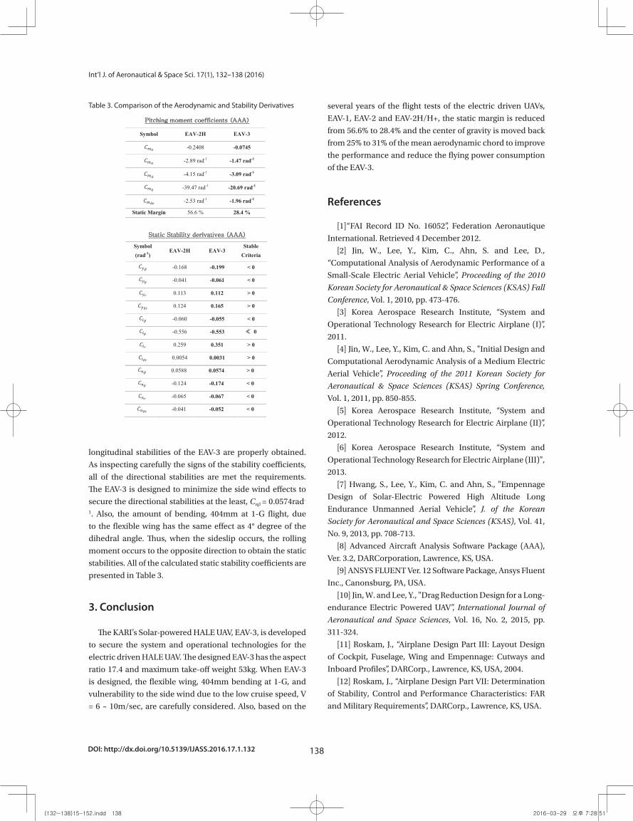
DOI: http://dx.doi.org/10.5139/IJASS.2016.17.1.132 138
Int’l J. of Aeronautical & Space Sci. 17(1), 132–138 (2016)
longitudinal stabilities of the EAV-3 are properly obtained.
As inspecting carefully the signs of the stability coefficients,
all of the directional stabilities are met the requirements.
The EAV-3 is designed to minimize the side wind effects to
secure the directional stabilities at the least, Cnβ = 0.0574rad-
1. Also, the amount of bending, 404mm at 1-G flight, due
to the flexible wing has the same effect as 4° degree of the
dihedral angle. Thus, when the sideslip occurs, the rolling
moment occurs to the opposite direction to obtain the static
stabilities. All of the calculated static stability coefficients are
presented in Table 3.
3. Conclusion
The KARI’s Solar-powered HALE UAV, EAV-3, is developed
to secure the system and operational technologies for the
electric driven HALE UAV. The designed EAV-3 has the aspect
ratio 17.4 and maximum take-off weight 53kg. When EAV-3
is designed, the flexible wing, 404mm bending at 1-G, and
vulnerability to the side wind due to the low cruise speed, V
= 6 ~ 10m/sec, are carefully considered. Also, based on the
several years of the flight tests of the electric driven UAVs,
EAV-1, EAV-2 and EAV-2H/H+, the static margin is reduced
from 56.6% to 28.4% and the center of gravity is moved back
from 25% to 31% of the mean aerodynamic chord to improve
the performance and reduce the flying power consumption
of the EAV-3.
References
[1]“FAI Record ID No. 16052”, Federation Aeronautique
International. Retrieved 4 December 2012.
[2] Jin, W., Lee, Y., Kim, C., Ahn, S. and Lee, D.,
“Computational Analysis of Aerodynamic Performance of a
Small-Scale Electric Aerial Vehicle”, Proceeding of the 2010
Korean Society for Aeronautical & Space Sciences (KSAS) Fall
Conference, Vol. 1, 2010, pp. 473-476.
[3] Korea Aerospace Research Institute, “System and
Operational Technology Research for Electric Airplane (I)”,
2011.
[4] Jin, W., Lee, Y., Kim, C. and Ahn, S., "Initial Design and
Computational Aerodynamic Analysis of a Medium Electric
Aerial Vehicle”, Proceeding of the 2011 Korean Society for
Aeronautical & Space Sciences (KSAS) Spring Conference,
Vol. 1, 2011, pp. 850-855.
[5] Korea Aerospace Research Institute, “System and
Operational Technology Research for Electric Airplane (II)”,
2012.
[6] Korea Aerospace Research Institute, “System and
Operational Technology Research for Electric Airplane (III)",
2013.
[7] Hwang, S., Lee, Y., Kim, C. and Ahn, S., "Empennage
Design of Solar-Electric Powered High Altitude Long
Endurance Unmanned Aerial Vehicle”, J. of the Korean
Society for Aeronautical and Space Sciences (KSAS), Vol. 41,
No. 9, 2013, pp. 708-713.
[8] Advanced Aircraft Analysis Software Package (AAA),
Ver. 3.2, DARCorporation, Lawrence, KS, USA.
[9] ANSYS FLUENT Ver. 12 Software Package, Ansys Fluent
Inc., Canonsburg, PA, USA.
[10] Jin, W. and Lee, Y., "Drag Reduction Design for a Long-
endurance Electric Powered UAV”, International Journal of
Aeronautical and Space Sciences, Vol. 16, No. 2, 2015, pp.
311-324.
[11] Roskam, J., “Airplane Design Part III: Layout Design
of Cockpit, Fuselage, Wing and Empennage: Cutways and
Inboard Profiles”, DARCorp., Lawrence, KS, USA, 2004.
[12] Roskam, J., “Airplane Design Part VII: Determination
of Stability, Control and Performance Characteristics: FAR
and Military Requirements”, DARCorp., Lawrence, KS, USA.
Table 3. Comparison of the Aerodynamic and Stability Derivatives
Fig. 11. Schematic Drawing of EAV-3. Table 3. Comparison of the Aerodynamic and
Stability Derivatives
Pitching moment coefficients (AAA)
Symbol EAV-2H EAV-3
𝐶𝐶𝑚𝑚0 -0.2408 -0.0745
𝐶𝐶𝑚𝑚𝛼𝛼 -2.89 rad-1 -1.47 rad-1
𝐶𝐶𝑚𝑚�̇�𝛼 -4.15 rad-1 -3.09 rad-1
𝐶𝐶𝑚𝑚𝑞𝑞 -39.47 rad-1 -20.69 rad-1
𝐶𝐶𝑚𝑚𝛿𝛿𝛿𝛿 -2.53 rad-1 -1.96 rad-1
Static Margin 56.6 % 28.4 %
Static Stability derivatives (AAA) Symbol (rad-1)
EAV-2H EAV-3Stable
Criteria
𝐶𝐶𝑦𝑦𝛽𝛽 -0.168 -0.199 < 0
𝐶𝐶𝑦𝑦𝑝𝑝 -0.041 -0.061 < 0
𝐶𝐶𝑦𝑦𝑟𝑟 0.113 0.112 > 0
𝐶𝐶𝑦𝑦𝛿𝛿𝑟𝑟 0.124 0.165 > 0
𝐶𝐶𝑙𝑙𝛽𝛽 -0.060 -0.055 < 0
𝐶𝐶𝑙𝑙𝑝𝑝 -0.556 -0.553 ≪ 0
𝐶𝐶𝑙𝑙𝑟𝑟 0.259 0.351 > 0
𝐶𝐶𝑙𝑙𝛿𝛿𝑟𝑟 0.0054 0.0031 > 0
𝐶𝐶𝑛𝑛𝛽𝛽 0.0588 0.0574 > 0
𝐶𝐶𝑛𝑛𝑝𝑝 -0.124 -0.174 < 0
𝐶𝐶𝑛𝑛𝑟𝑟 -0.065 -0.067 < 0
𝐶𝐶𝑛𝑛𝛿𝛿𝑟𝑟 -0.041 -0.052 < 0
3. Conclusion
The KARI’s Solar-powered HALE UAV,
EAV-3, is developed to secure the system and operational technologies for the electric driven HALE UAV. The designed EAV-3 has the aspect ratio 17.4 and maximum take-off weight 53kg. When EAV-3 is designed, the flexible wing, 404mm bending at 1-G, and vulnerability to the side wind due to the low cruise speed, V = 6 ~ 10m/sec, are carefully considered. Also, based on the several years of the flight tests of the electric driven UAVs, EAV-1, EAV-2 and EAV-2H/H+, the static margin is reduced from 56.6% to 28.4% and the center of gravity is moved back from 25% to 31% of the mean aerodynamic chord to improve the performance and reduce the flying power consumption of the EAV-3.
References
[1]“FAI Record ID No. 16052”, Federation
Aeronautique International. Retrieved 4
December 2012.
[2] Jin, W., Lee, Y., Kim, C., Ahn, S., and Lee,
D., “Computational Analysis of Aerodynamic
Performance of a Small-Scale Electric Aerial
Vehicle”, Proceeding of the 2010 Korean
Society for Aeronautical & Space Sciences
(KSAS) Fall Conference, Vol. 1, 2010, pp. 473-
476.
[3] Korea Aerospace Research Institute,
“System and Operational Technology Research
for Electric Airplane (I)”, 2011.
[4] Jin, W., Lee, Y., Kim, C., and Ahn, S.,
"Initial Design and Computational Aerodynamic
Analysis of a Medium Electric Aerial Vehicle”,
Proceeding of the 2011 Korean Society for
Aeronautical & Space Sciences (KSAS) Spring
Conference, Vol. 1, 2011, pp. 850-855.
[5] Korea Aerospace Research Institute,
“System and Operational Technology Research
for Electric Airplane (II)”, 2012.
[6] Korea Aerospace Research Institute,
“System and Operational Technology Research
for Electric Airplane (III)", 2013.
(132~138)15-152.indd 138 2016-03-29 오후 7:28:51


![Conceptual Design Optimization of Tensairity Girder Using ...past.ijass.org/On_line/admin/files/(29~36)15-076.pdf · adaptive sampling method [9] are used to build the surrogate model](https://img.pdfslide.us/doc/110x75/6061be112ccc0b142c43805d/conceptual-design-optimization-of-tensairity-girder-using-pastijassorgonlineadminfiles293615-076pdf.jpg)


![Sensitivity analysis of transonic flow past a NASA …past.ijass.org/On_line/admin/files/(232~240)14-020.pdf10%-thick supercritical NASA SC(2)-0710 airfoil [9]: 2 not thoroughly investigated](https://img.pdfslide.us/doc/110x75/5ac15cd07f8b9a357e8c9682/sensitivity-analysis-of-transonic-flow-past-a-nasa-pastijassorgonlineadminfiles23224014-020pdf10-thick.jpg)


