Embed Size (px)
Citation preview
EasyChair Preprint№ 6354
Aerodynamic Design and Performance Analysisof the Ultra-High Expansion Ratio Turbine forTrans-Media Engines
Siyu Wu, Jie Gao, Cheng Zhou and Weiliang Fu
EasyChair preprints are intended for rapiddissemination of research results and areintegrated with the rest of EasyChair.
August 23, 2021
Proceedings of Global Power and Propulsion Society ISSN-Nr: 2504-4400
GPPS Xi’an21 18th – 20th October, 2021
www.gpps.global
GPPS-TC-2021-0125
Aerodynamic design and performance analysis of the ultra-high expansion ratio turbine for
trans-media engines Siyu Wu
College of Power and Energy Engineering,
Harbin Engineering University
Harbin, Heilongjiang, P.R.C
Jie Gao*
College of Power and Energy Engineering,
Harbin Engineering University
Harbin, Heilongjiang, P.R.C
Cheng Zhou
College of Power and Energy Engineering,
Harbin Engineering University
Weliang Fu
College of Power and Energy Engineering,
Harbin Engineering University
[email protected], Harbin, Heilongjiang, P.R.C
Abstract
In order to produce more specific work in trans-
media engines, which features low-mass flow feeding
systems, the flow loss of ultra-high expansion turbine with
single stage need to be studied further. In this paper, the
numerical method was used to carry out calculations for
turbines in both air and underwater working conditions,
and the flow fields inside the flow passage of ultra-high
expansion ratio turbines are studied in detail. The results
show that the power, efficiency and flow requirements of
the engine in the air condition and underwater conditions
can be met by changing the number of nozzles and the
throat area while keeping the blades unchanged. In
underwater working conditions, shock waves are formed
obviously between one nozzle outlet and suction surfaces
of three rotor blades, while in the air conditions, shock
waves are only formed between one nozzle outlet and
suction surface of two rotor blades . Therefore, overall, the
efficiency in the underwater condition is significantly less
than that in the air condition. In the both conditions, the gas
in the blade passage corresponding to the circumferential
gap between the two nozzles generates vortices due to
mutual mixing, resulting in vortex losses.
Keywords: Trans-media engine, Ultra-high expansion
ratio turbine, Shock wave, Aerodynamics
Introduction
The dynamic system of underwater vehicles has a
decisive influence on its performance. Since long range
and fast speed are the development trend of future
underwater vehicles, thermal-power system engines have
great advantages. For the production of underwater
vehicles, most countries use the thermal propulsion system.
Due to the volume requirements of the vehicle, the piston
engine is only suitable for working in the case of low-
power requirements. The turbine engine is used more and
more widely, as a rotating machine, the vibration of the
engine is small, which can meet the requirements of high-
power vehicles. So turbine engine represents the
development trend of future underwater vehicle power
system [1-4].
The turbine adopted by the water-air medium aircraft
has the advantages of small size and large power, which
can meet the requirements of the aircraft in air and
underwater conditions [5]. Wang [6] described the progress
in computer technology and the development of
computational fluid dynamics in recent years. The study of
the flow inside the impeller is changed from the past
experiments to the application of computational fluid
dynamics, which can greatly improve the efficiency and
save time resources.
Yi et al. [7] carried out numerical calculations on the
flows in the moving blades of some partial inlet turbines,
and found that there were many vortices in the flow
passage, which would cause energy dissipation and
increase the loss. Yi et al. [8] studied the complex internal
flows of a turbine by calculating its flow field in variable
working conditions, and found that the results were
relatively close to the experimental data. Gas flow in some
partial inlet turbines has no rules to follow, because the gas
flowing around the blades is viscous, and a boundary layer
will be formed around the blades. Changes in blade surface
pressure will lead to secondary flows, vortexes and other
flow phenomena, thus resulting in flow losses.
Guo et al. [9] carried out numerical simulation on
pure impulse turbine, and carefully analyzed the
temperature change, load change and loss change in the
flow passage corresponding to the rotor blade of the nozzle.
It was found that the higher the blade load, the lower the
temperature, and the smaller the temperature gradient.
Liu et al. [10] carried out unsteady calculation for a
single stage turbine with a large expansion ratio up to 30.
It was found that the wake of the nozzle changed greatly
along the radial direction, and there were various wave
systems in the rotor blade passage. Chen et al. [11] used
CFX to calculate torpedo turbine and analyzed rotor blade
runner. It was found that oblique shock waves appeared at
the trailing edge of rotor blade, forming swallowtail vortex.
Chen et al. [12-13] studied local inlet turbines and
found that the distribution of static pressure along the
circumferential direction was uneven, and the pressure
distribution on the blade surface at different positions was
also different. It is found that the total static efficiency of
the re-entry turbine will increase after adjustment.
As seen, there was a lot of research in ultra-high
expansion ratio turbine, but there is little research about the
flow loss mechanism in trans-media engine. Therefore, it
is necessary to analyze the complex internal flows of
turbines used in trans-media engine.
In this paper, CFX, computational fluid software, is
used to calculate the whole cycle of some partial inlet
turbines in the air condition and under-water conditions,
and analyze the flow phenomena of the flow passage inside
the turbine in the inlet area and the load on the blades.
Numerical method
Nozzle calculation model
According to the total inlet temperature T, flow
rate and expansion ratio, the isentropic velocity at the
nozzle outlet can be obtained through formula (1):
𝑣1 = √2ℎ∗ (1)
In formula (1),ℎ∗is the isentropic enthalpy drop
in the nozzle;𝑣1 is the ideal velocity of nozzle outlet.
Apply formula (2) to calculate the area:
�̇� = 𝜌𝑣𝐴 (2)
In formula (2), A is the area of nozzle inlet, outlet and
throat; v is the velocity of inlet, outlet and throat; ρ is the
gas density of nozzle inlet, outlet and throat.
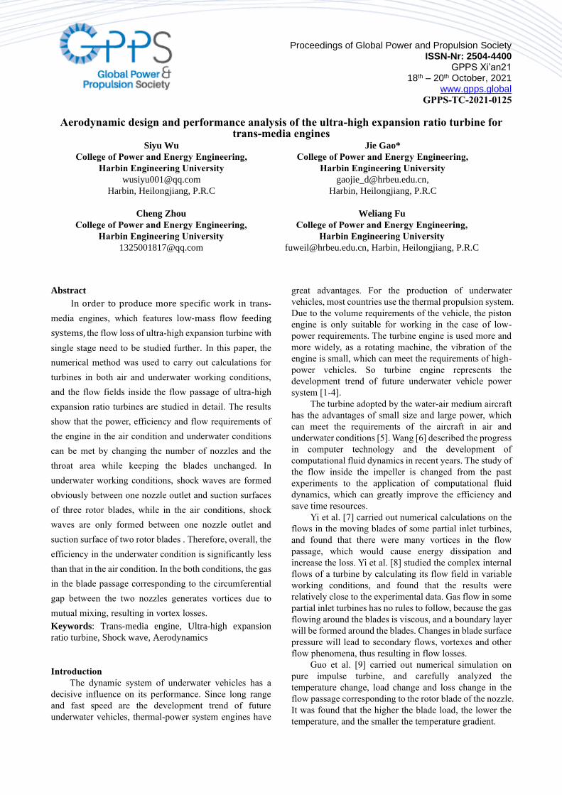
𝑙 =𝑑1 − 𝑑cr
2𝑡𝑎𝑛 (𝜑2) (3)
In formula (3), 𝑑1 is the diameter of nozzle
outlet; 𝑑cr is the radius of the nozzle throat; 𝜑is the
tip cone Angle of the nozzle. The shape and size of
the nozzle can be drawn through formula (1) ~ (3), as
shown in Fig. 1.
Since this turbine stage is a single-stage turbine,
the enthalpy drop is very large. In addition, when the
gas flows out of the nozzle outlet after expansion in
the nozzle, the speed reaches the supersonic, and the
speed is used to push the turbine blades to do work.
Figure 1. Nozzle model
Turbine blade calculation model
Because the fuel carried by the aircraft is certain,
the mass flow through the turbine is very small,
partial inlet turbines are widely used. Considering
the height of turbine blades is also relatively small, it
is very complicated to make complex blade shapes on
short blades. Therefore, for the convenience of design
and manufacturing, the blade profile is drawn by
lines and circles, as shown in Fig. 2.
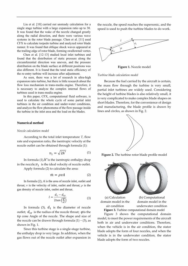
Figure 2. The turbine rotor blade profile model
(a) Calculation
domain model in the
air condition
(b) Computational
domain model in the
underwater condition Figure 3. Turbine computational domain model
Figure 3 shows the computational domain
model, to meet the power requirements of the aircraft
both in air and underwater conditions. Therefore,
when the vehicle is in the air condition, the stator
blade adopts the form of four nozzles, and when the
vehicle is in the underwater condition, the stator
blade adopts the form of two nozzles.
The numerical simulation
Because the nozzle is not in a form of
circumferential symmetrical distribution structures, it is
necessary to conduct a full cycle numerical calculation
on the turbine. In order to achieve better data transfer
between rotor and stator, a ring of transition was
connected at the nozzle outlet and the frozen rotor
method was adopted for data transfer between rotor and
stator. In this paper, the computational fluid software
ANSYS CFX 17.0 is used for numerical calculation of
the turbine. The turbulence model adopts k-w, and the
near-wall surface adopts Automatic for wall surface
treatment. The nozzle inlet is given the total inlet
temperature and total pressure, the moving blade outlet
is given the static pressure, and the wall surface is given
the adiabatic and non-slip boundary conditions
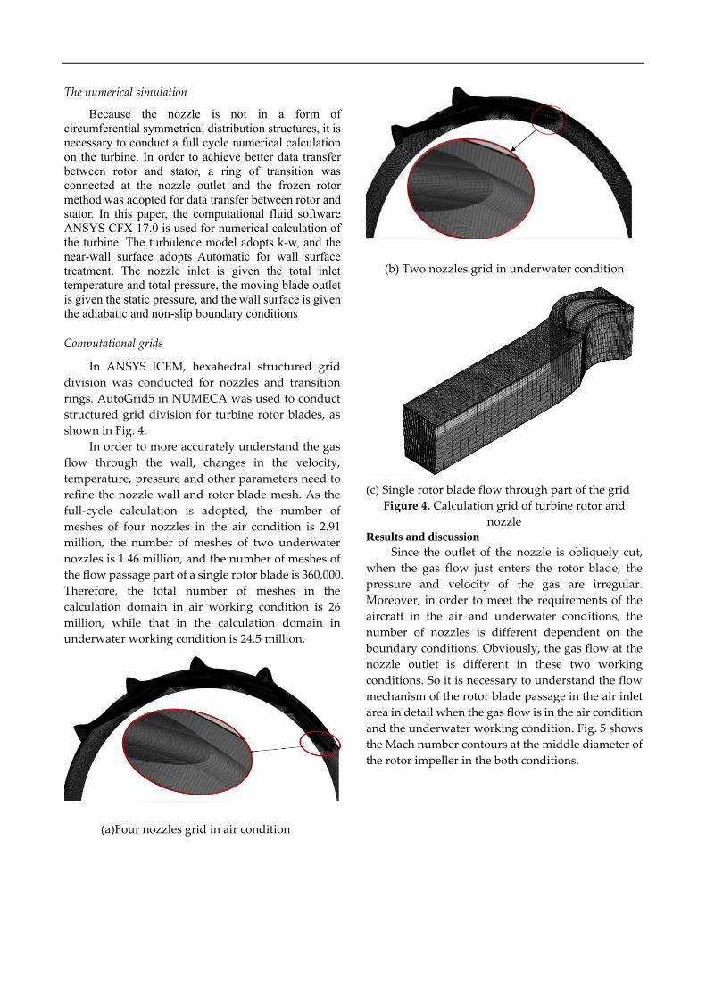
Computational grids
In ANSYS ICEM, hexahedral structured grid
division was conducted for nozzles and transition
rings. AutoGrid5 in NUMECA was used to conduct
structured grid division for turbine rotor blades, as
shown in Fig. 4.
In order to more accurately understand the gas
flow through the wall, changes in the velocity,
temperature, pressure and other parameters need to
refine the nozzle wall and rotor blade mesh. As the
full-cycle calculation is adopted, the number of
meshes of four nozzles in the air condition is 2.91
million, the number of meshes of two underwater
nozzles is 1.46 million, and the number of meshes of
the flow passage part of a single rotor blade is 360,000.
Therefore, the total number of meshes in the
calculation domain in air working condition is 26
million, while that in the calculation domain in
underwater working condition is 24.5 million.
(a)Four nozzles grid in air condition
(b) Two nozzles grid in underwater condition
(c) Single rotor blade flow through part of the grid
Figure 4. Calculation grid of turbine rotor and
nozzle Results and discussion
Since the outlet of the nozzle is obliquely cut,
when the gas flow just enters the rotor blade, the
pressure and velocity of the gas are irregular.
Moreover, in order to meet the requirements of the
aircraft in the air and underwater conditions, the
number of nozzles is different dependent on the
boundary conditions. Obviously, the gas flow at the
nozzle outlet is different in these two working
conditions. So it is necessary to understand the flow
mechanism of the rotor blade passage in the air inlet
area in detail when the gas flow is in the air condition
and the underwater working condition. Fig. 5 shows
the Mach number contours at the middle diameter of
the rotor impeller in the both conditions.
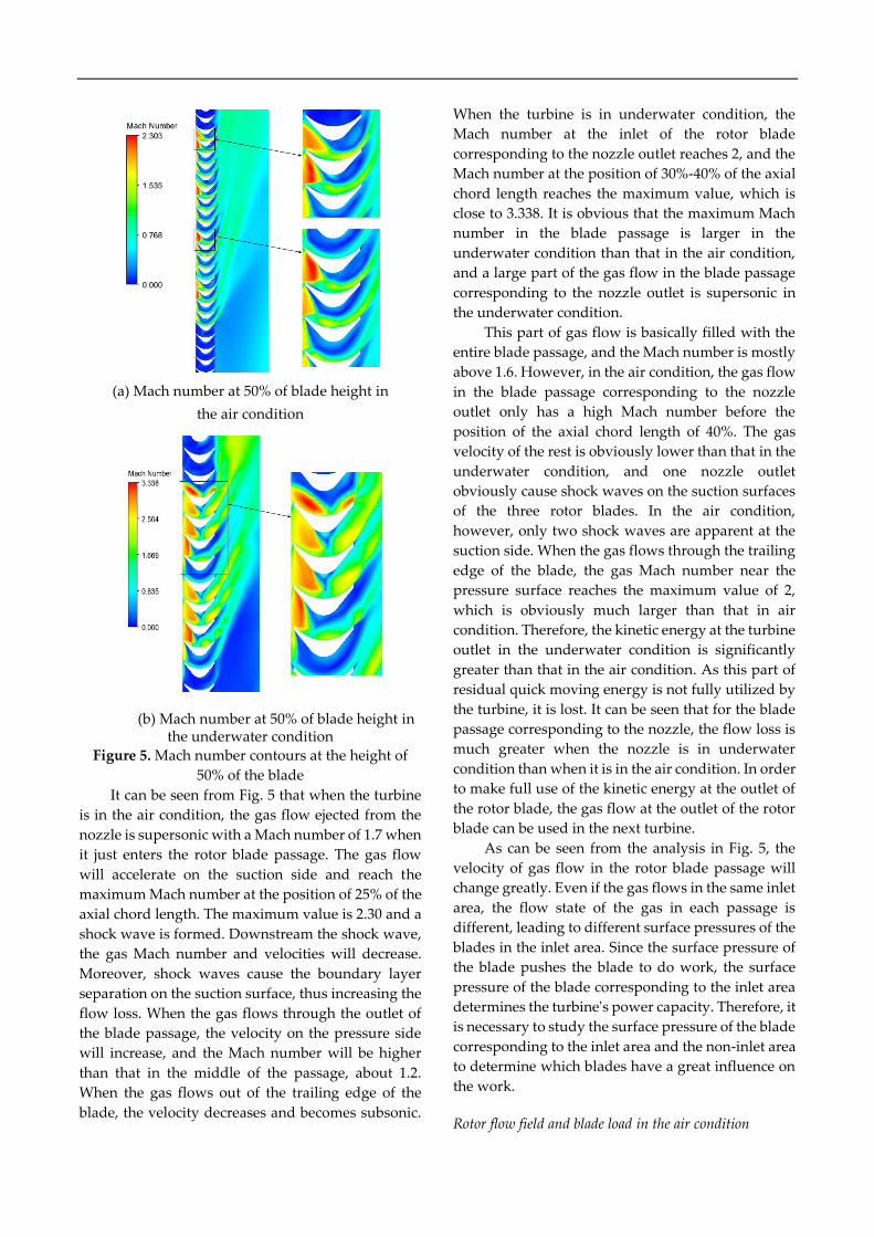
(a) Mach number at 50% of blade height in
the air condition
(b) Mach number at 50% of blade height in the underwater condition
Figure 5. Mach number contours at the height of
50% of the blade
It can be seen from Fig. 5 that when the turbine
is in the air condition, the gas flow ejected from the
nozzle is supersonic with a Mach number of 1.7 when
it just enters the rotor blade passage. The gas flow
will accelerate on the suction side and reach the
maximum Mach number at the position of 25% of the
axial chord length. The maximum value is 2.30 and a
shock wave is formed. Downstream the shock wave,
the gas Mach number and velocities will decrease.
Moreover, shock waves cause the boundary layer
separation on the suction surface, thus increasing the
flow loss. When the gas flows through the outlet of
the blade passage, the velocity on the pressure side
will increase, and the Mach number will be higher
than that in the middle of the passage, about 1.2.
When the gas flows out of the trailing edge of the
blade, the velocity decreases and becomes subsonic.
When the turbine is in underwater condition, the
Mach number at the inlet of the rotor blade
corresponding to the nozzle outlet reaches 2, and the
Mach number at the position of 30%-40% of the axial
chord length reaches the maximum value, which is
close to 3.338. It is obvious that the maximum Mach
number in the blade passage is larger in the
underwater condition than that in the air condition,
and a large part of the gas flow in the blade passage
corresponding to the nozzle outlet is supersonic in
the underwater condition.
This part of gas flow is basically filled with the
entire blade passage, and the Mach number is mostly
above 1.6. However, in the air condition, the gas flow
in the blade passage corresponding to the nozzle
outlet only has a high Mach number before the
position of the axial chord length of 40%. The gas
velocity of the rest is obviously lower than that in the
underwater condition, and one nozzle outlet
obviously cause shock waves on the suction surfaces
of the three rotor blades. In the air condition,
however, only two shock waves are apparent at the
suction side. When the gas flows through the trailing
edge of the blade, the gas Mach number near the
pressure surface reaches the maximum value of 2,
which is obviously much larger than that in air
condition. Therefore, the kinetic energy at the turbine
outlet in the underwater condition is significantly
greater than that in the air condition. As this part of
residual quick moving energy is not fully utilized by
the turbine, it is lost. It can be seen that for the blade
passage corresponding to the nozzle, the flow loss is
much greater when the nozzle is in underwater
condition than when it is in the air condition. In order
to make full use of the kinetic energy at the outlet of
the rotor blade, the gas flow at the outlet of the rotor
blade can be used in the next turbine.
As can be seen from the analysis in Fig. 5, the
velocity of gas flow in the rotor blade passage will
change greatly. Even if the gas flows in the same inlet
area, the flow state of the gas in each passage is
different, leading to different surface pressures of the
blades in the inlet area. Since the surface pressure of
the blade pushes the blade to do work, the surface
pressure of the blade corresponding to the inlet area
determines the turbine's power capacity. Therefore, it
is necessary to study the surface pressure of the blade
corresponding to the inlet area and the non-inlet area
to determine which blades have a great influence on
the work.
Rotor flow field and blade load in the air condition
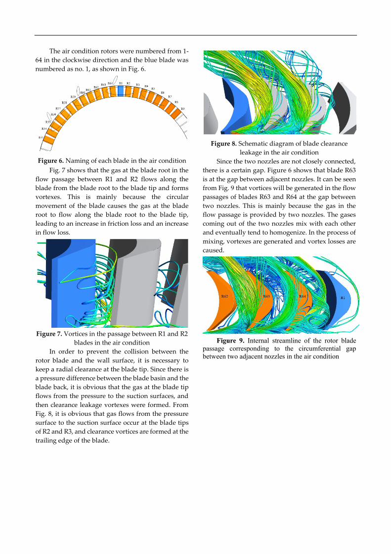
The air condition rotors were numbered from 1-
64 in the clockwise direction and the blue blade was
numbered as no. 1, as shown in Fig. 6.
Figure 6. Naming of each blade in the air condition
Fig. 7 shows that the gas at the blade root in the
flow passage between R1 and R2 flows along the
blade from the blade root to the blade tip and forms
vortexes. This is mainly because the circular
movement of the blade causes the gas at the blade
root to flow along the blade root to the blade tip,
leading to an increase in friction loss and an increase
in flow loss.
Figure 7. Vortices in the passage between R1 and R2
blades in the air condition
In order to prevent the collision between the
rotor blade and the wall surface, it is necessary to
keep a radial clearance at the blade tip. Since there is
a pressure difference between the blade basin and the
blade back, it is obvious that the gas at the blade tip
flows from the pressure to the suction surfaces, and
then clearance leakage vortexes were formed. From
Fig. 8, it is obvious that gas flows from the pressure
surface to the suction surface occur at the blade tips
of R2 and R3, and clearance vortices are formed at the
trailing edge of the blade.
Figure 8. Schematic diagram of blade clearance
leakage in the air condition
Since the two nozzles are not closely connected,
there is a certain gap. Figure 6 shows that blade R63
is at the gap between adjacent nozzles. It can be seen
from Fig. 9 that vortices will be generated in the flow
passages of blades R63 and R64 at the gap between
two nozzles. This is mainly because the gas in the
flow passage is provided by two nozzles. The gases
coming out of the two nozzles mix with each other
and eventually tend to homogenize. In the process of
mixing, vortexes are generated and vortex losses are
caused.
Figure 9. Internal streamline of the rotor blade
passage corresponding to the circumferential gap
between two adjacent nozzles in the air condition
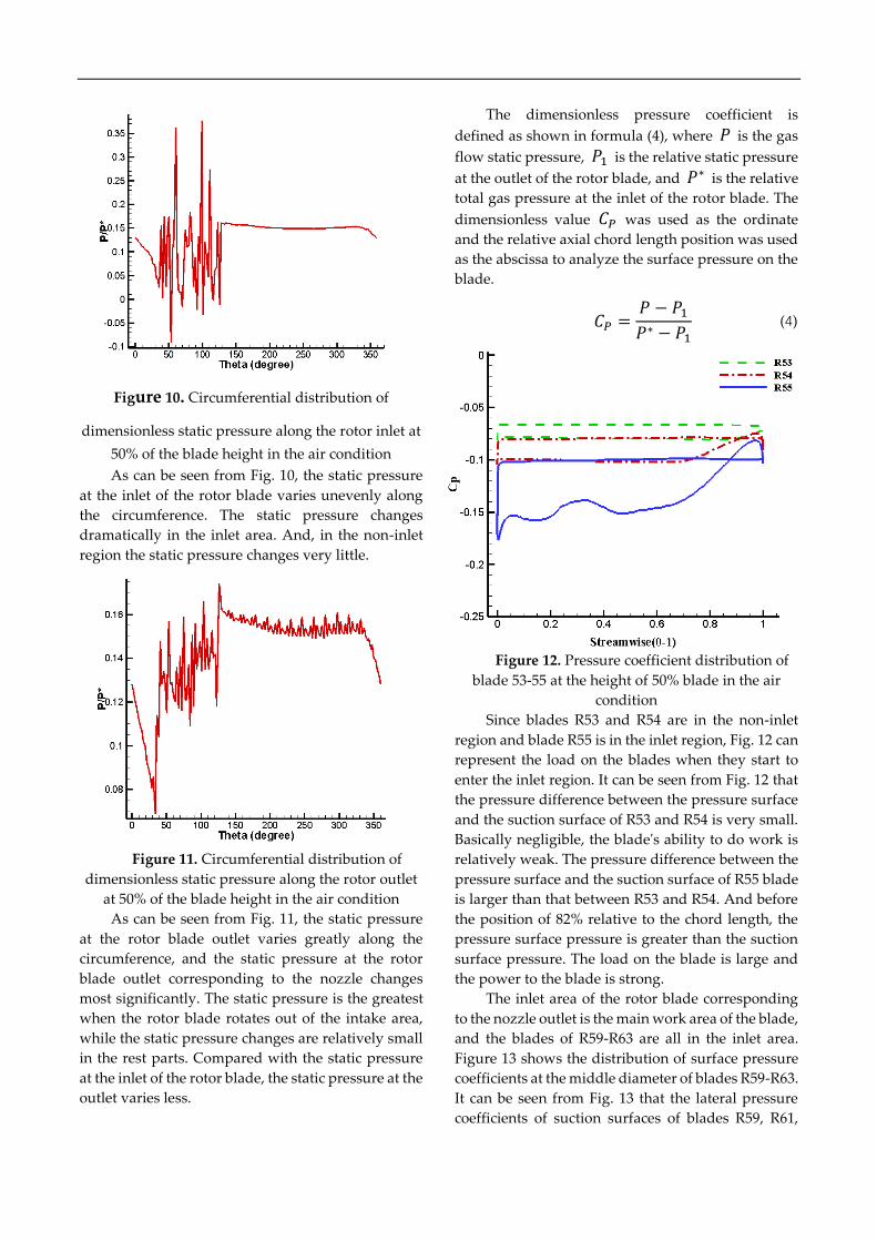
Figure 10. Circumferential distribution of
dimensionless static pressure along the rotor inlet at
50% of the blade height in the air condition
As can be seen from Fig. 10, the static pressure
at the inlet of the rotor blade varies unevenly along
the circumference. The static pressure changes
dramatically in the inlet area. And, in the non-inlet
region the static pressure changes very little.
Figure 11. Circumferential distribution of
dimensionless static pressure along the rotor outlet
at 50% of the blade height in the air condition
As can be seen from Fig. 11, the static pressure
at the rotor blade outlet varies greatly along the
circumference, and the static pressure at the rotor
blade outlet corresponding to the nozzle changes
most significantly. The static pressure is the greatest
when the rotor blade rotates out of the intake area,
while the static pressure changes are relatively small
in the rest parts. Compared with the static pressure
at the inlet of the rotor blade, the static pressure at the
outlet varies less.
The dimensionless pressure coefficient is
defined as shown in formula (4), where 𝑃 is the gas
flow static pressure, 𝑃1 is the relative static pressure
at the outlet of the rotor blade, and 𝑃∗ is the relative
total gas pressure at the inlet of the rotor blade. The
dimensionless value 𝐶𝑃 was used as the ordinate
and the relative axial chord length position was used
as the abscissa to analyze the surface pressure on the
blade.
Figure 12. Pressure coefficient distribution of
blade 53-55 at the height of 50% blade in the air
condition
Since blades R53 and R54 are in the non-inlet
region and blade R55 is in the inlet region, Fig. 12 can
represent the load on the blades when they start to
enter the inlet region. It can be seen from Fig. 12 that
the pressure difference between the pressure surface
and the suction surface of R53 and R54 is very small.
Basically negligible, the blade's ability to do work is
relatively weak. The pressure difference between the
pressure surface and the suction surface of R55 blade
is larger than that between R53 and R54. And before
the position of 82% relative to the chord length, the
pressure surface pressure is greater than the suction
surface pressure. The load on the blade is large and
the power to the blade is strong.
The inlet area of the rotor blade corresponding
to the nozzle outlet is the main work area of the blade,
and the blades of R59-R63 are all in the inlet area.
Figure 13 shows the distribution of surface pressure
coefficients at the middle diameter of blades R59-R63.
It can be seen from Fig. 13 that the lateral pressure
coefficients of suction surfaces of blades R59, R61,
𝐶𝑃 =𝑃 − 𝑃1𝑃∗ − 𝑃1
(4)
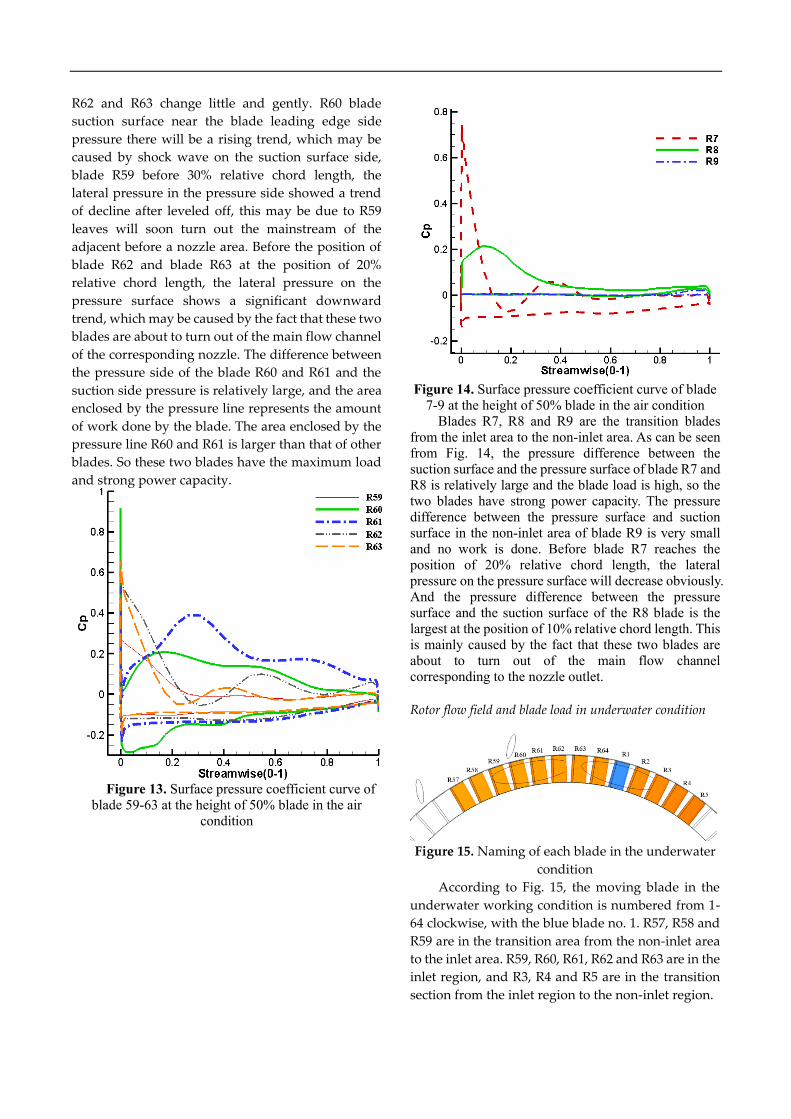
R62 and R63 change little and gently. R60 blade
suction surface near the blade leading edge side
pressure there will be a rising trend, which may be
caused by shock wave on the suction surface side,
blade R59 before 30% relative chord length, the
lateral pressure in the pressure side showed a trend
of decline after leveled off, this may be due to R59
leaves will soon turn out the mainstream of the
adjacent before a nozzle area. Before the position of
blade R62 and blade R63 at the position of 20%
relative chord length, the lateral pressure on the
pressure surface shows a significant downward
trend, which may be caused by the fact that these two
blades are about to turn out of the main flow channel
of the corresponding nozzle. The difference between
the pressure side of the blade R60 and R61 and the
suction side pressure is relatively large, and the area
enclosed by the pressure line represents the amount
of work done by the blade. The area enclosed by the
pressure line R60 and R61 is larger than that of other
blades. So these two blades have the maximum load
and strong power capacity.
Figure 13. Surface pressure coefficient curve of
blade 59-63 at the height of 50% blade in the air
condition
Figure 14. Surface pressure coefficient curve of blade
7-9 at the height of 50% blade in the air condition
Blades R7, R8 and R9 are the transition blades
from the inlet area to the non-inlet area. As can be seen
from Fig. 14, the pressure difference between the
suction surface and the pressure surface of blade R7 and
R8 is relatively large and the blade load is high, so the
two blades have strong power capacity. The pressure
difference between the pressure surface and suction
surface in the non-inlet area of blade R9 is very small
and no work is done. Before blade R7 reaches the
position of 20% relative chord length, the lateral
pressure on the pressure surface will decrease obviously.
And the pressure difference between the pressure
surface and the suction surface of the R8 blade is the
largest at the position of 10% relative chord length. This
is mainly caused by the fact that these two blades are
about to turn out of the main flow channel
corresponding to the nozzle outlet.
Rotor flow field and blade load in underwater condition
Figure 15. Naming of each blade in the underwater
condition
According to Fig. 15, the moving blade in the
underwater working condition is numbered from 1-
64 clockwise, with the blue blade no. 1. R57, R58 and
R59 are in the transition area from the non-inlet area
to the inlet area. R59, R60, R61, R62 and R63 are in the
inlet region, and R3, R4 and R5 are in the transition
section from the inlet region to the non-inlet region.
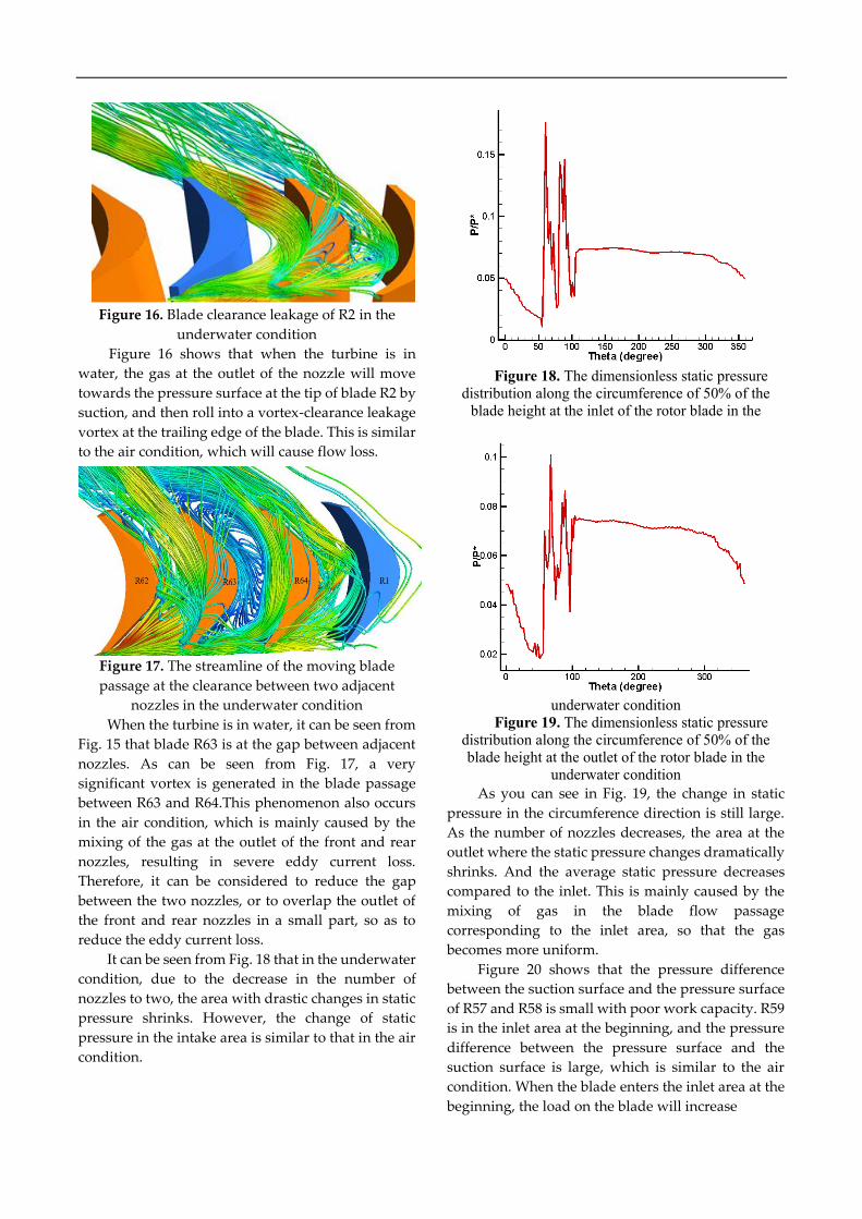
Figure 16. Blade clearance leakage of R2 in the
underwater condition
Figure 16 shows that when the turbine is in
water, the gas at the outlet of the nozzle will move
towards the pressure surface at the tip of blade R2 by
suction, and then roll into a vortex-clearance leakage
vortex at the trailing edge of the blade. This is similar
to the air condition, which will cause flow loss.
Figure 17. The streamline of the moving blade
passage at the clearance between two adjacent
nozzles in the underwater condition
When the turbine is in water, it can be seen from
Fig. 15 that blade R63 is at the gap between adjacent
nozzles. As can be seen from Fig. 17, a very
significant vortex is generated in the blade passage
between R63 and R64.This phenomenon also occurs
in the air condition, which is mainly caused by the
mixing of the gas at the outlet of the front and rear
nozzles, resulting in severe eddy current loss.
Therefore, it can be considered to reduce the gap
between the two nozzles, or to overlap the outlet of
the front and rear nozzles in a small part, so as to
reduce the eddy current loss.
It can be seen from Fig. 18 that in the underwater
condition, due to the decrease in the number of
nozzles to two, the area with drastic changes in static
pressure shrinks. However, the change of static
pressure in the intake area is similar to that in the air
condition.
Figure 18. The dimensionless static pressure
distribution along the circumference of 50% of the
blade height at the inlet of the rotor blade in the
underwater condition
Figure 19. The dimensionless static pressure
distribution along the circumference of 50% of the
blade height at the outlet of the rotor blade in the
underwater condition
As you can see in Fig. 19, the change in static
pressure in the circumference direction is still large.
As the number of nozzles decreases, the area at the
outlet where the static pressure changes dramatically
shrinks. And the average static pressure decreases
compared to the inlet. This is mainly caused by the
mixing of gas in the blade flow passage
corresponding to the inlet area, so that the gas
becomes more uniform.
Figure 20 shows that the pressure difference
between the suction surface and the pressure surface
of R57 and R58 is small with poor work capacity. R59
is in the inlet area at the beginning, and the pressure
difference between the pressure surface and the
suction surface is large, which is similar to the air
condition. When the blade enters the inlet area at the
beginning, the load on the blade will increase
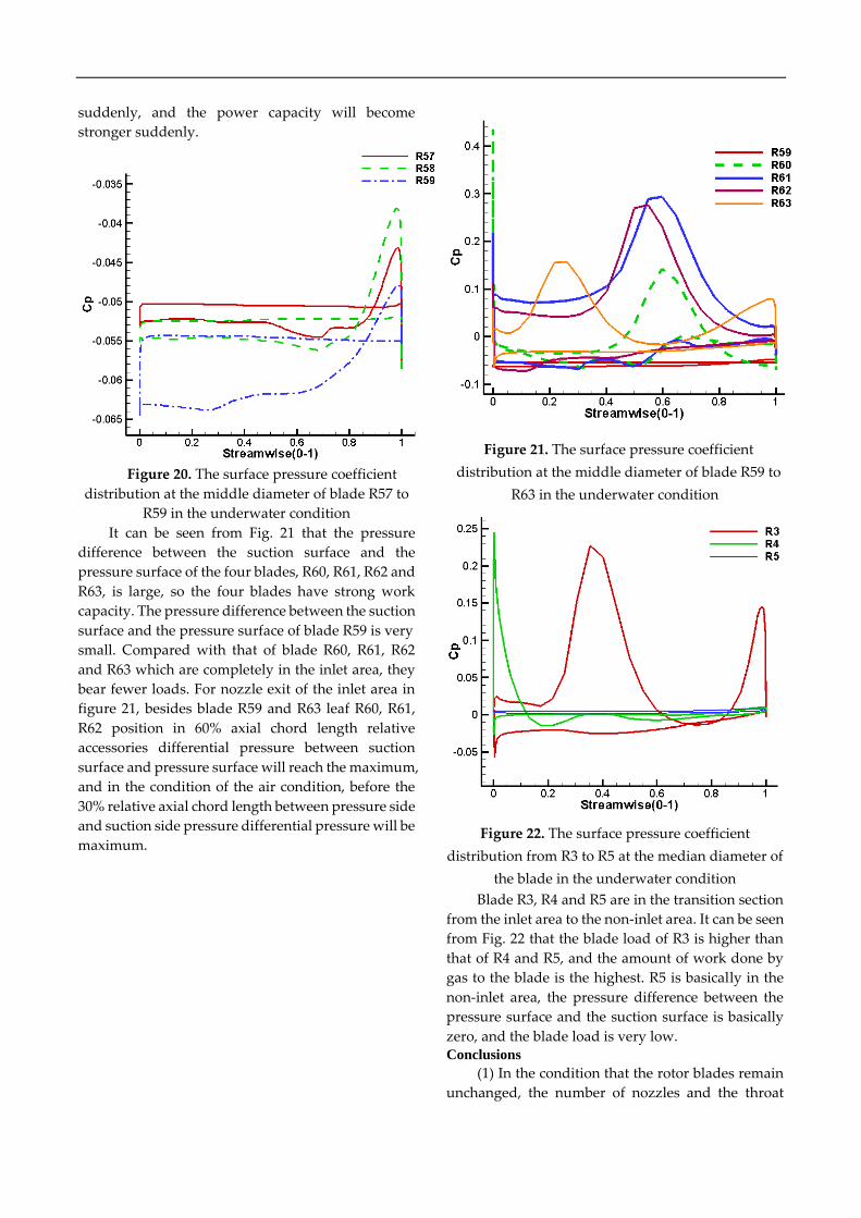
suddenly, and the power capacity will become
stronger suddenly.
Figure 20. The surface pressure coefficient
distribution at the middle diameter of blade R57 to
R59 in the underwater condition
It can be seen from Fig. 21 that the pressure
difference between the suction surface and the
pressure surface of the four blades, R60, R61, R62 and
R63, is large, so the four blades have strong work
capacity. The pressure difference between the suction
surface and the pressure surface of blade R59 is very
small. Compared with that of blade R60, R61, R62
and R63 which are completely in the inlet area, they
bear fewer loads. For nozzle exit of the inlet area in
figure 21, besides blade R59 and R63 leaf R60, R61,
R62 position in 60% axial chord length relative
accessories differential pressure between suction
surface and pressure surface will reach the maximum,
and in the condition of the air condition, before the
30% relative axial chord length between pressure side
and suction side pressure differential pressure will be
maximum.
Figure 21. The surface pressure coefficient
distribution at the middle diameter of blade R59 to
R63 in the underwater condition
Figure 22. The surface pressure coefficient
distribution from R3 to R5 at the median diameter of
the blade in the underwater condition
Blade R3, R4 and R5 are in the transition section
from the inlet area to the non-inlet area. It can be seen
from Fig. 22 that the blade load of R3 is higher than
that of R4 and R5, and the amount of work done by
gas to the blade is the highest. R5 is basically in the
non-inlet area, the pressure difference between the
pressure surface and the suction surface is basically
zero, and the blade load is very low. Conclusions
(1) In the condition that the rotor blades remain
unchanged, the number of nozzles and the throat
area can be changed to meet the requirements of
power, efficiency and flow in the air and underwater
working conditions of the engine.
(2) In underwater working conditions, one
nozzle outlet will obviously cause shock waves on
the suction surfaces of three moving blades, while in
the air, it will only cause shock waves on the suction
surfaces of two moving blades. The fundamental
reason of this phenomenon is that the total inlet
pressure of nozzle in underwater working condition
is obviously higher than that in air working condition.
This will cause residual velocity loss, so the flow loss
of the turbine in the underwater working condition is
more than that in the air working condition.
Therefore, overall, the efficiency of underwater
conditions is significantly less efficient than that of air
conditions.
(3) Since the adjacent two nozzles are not closely
connected, there is a certain clearance, and vortices
will be generated in the blade passage at the
clearance of the two nozzles, regardless of the air
condition or the underwater condition. This is mainly
because the gas in the flow passage is provided by
two nozzles, and the gas coming out of the two
nozzles will mix with each other, and vortexes will be
generated in the process of change, resulting in eddy
loss. Therefore, it can be considered to reduce the gap
between the adjacent two nozzles, or to overlap the
outlet of the front and rear two nozzles in a small part,
so as to reduce the eddy current loss.
(4) The distribution law of pressure difference
between suction surface and pressure surface of the
blade at the air inlet area in air condition is obviously
different from that in water condition. When the
blade is in water, the pressure difference between the
suction surface and the pressure surface will reach
the maximum value near the position of 60% relative
to the axial chord length. In the air condition, the
maximum pressure difference between the pressure
surface and the suction surface pressure occurs
before the position of 30% relative to the axial chord
length.
(5) Because a radial clearance is required at the
blade tip, gas flowing from the pressure to the
suction surface at the blade tip will be generated in
the action of pressure difference, and then clearance
vortexes will be formed, which will cause clearance
leakage loss and affect turbine efficiency. Nomenclature
ℎ∗ isentropic enthalpy drop in the nozzle,
kJ
𝑣1 ideal velocity of nozzle outlet, m/s
𝐴 the area of nozzle inlet and outlet and
throat, m^2
𝑣 the velocity of inlet and outlet and
throat, m/s
𝜌 the gas density of nozzle inlet and
outlet and throat, kg/s
𝑑1 the diameter of nozzle outlet, m
𝑑𝑐𝑟 the radius of the nozzle throat, m
𝜑 the tip cone Angle of the nozzle, deg
𝐶𝑃 static pressure coefficient
𝑃 Pressure, MPa 𝑃
𝑃∗ ratio of local static pressure to inlet
relative total pressure
Acknowledgments
This work has been supported by the National Natural
Science Foundation of China (Grant No. 51979052,
51779051) and the Fundamental Research Funds for the
Central Universities (No. 307202CFT0304), which are
gratefully acknowledged.
References
[1] B Chen, P F Zhang, K Guo, Review of the
development in torpedo thermal power technologies.
Journal of Propulsion Technology, vol. 32, no. 3,
pp.447-450, 2011.
[2] S Z Wang, Z H Zhang, Y C Li, The Development of
the Torpedo Thermal Power Engine and the Selection
of the Engine Model. Torpedo Technology, vol.10, no.2,
pp.5-9, 2002.
[3] Z W Zha, A Summary of Development in Torpedo
Power Technologies. Torpedo Technology, vol.13, no.1,
pp.1-4, 2005.
[4] M Lai, G Y Qi, P F Zhu, Research on the development
of foreign torpedo power system. Ship Science and
Technology, vol. 36, no.8, pp.154-157, 2014.
[5] Z W Zha, X F Shi, Z B Qian, Technique of Torpedo
Thermal Power. Beijing: National Defense Industry
Press, 2006.
[6] F J Wang, Computational Fluid Dynamics Analysis.
Beijing: Tsinghua University Press, 2004.
[7] J B Yi, W B Zhao, H C Shi, et al. Numerical Simulation
on Inner Flow Field of Gas Turbine with Partial Inlet
Flow. Torpedo Technology, vol.18, no.6, pp.456-460,
2010.
[8] J B Yi, J P Qian, C P Dong, et al. Numerical
Investigation on Turbine flow field and performance
of underwater vehicle. Torpedo Technology, vol.17,no.4,
pp.61-66,2009.
[9] Z Y Guo, H Cao, W B Zhao, Numerical Simulation of
Supersonic Flow Field in Rotor Blade Cascade for
Impulse Torpedo Turbine. Torpedo Technology, vol.21,
no.1, pp.43-47, 2013.
[10] G T Liu, H Y Huang, X F Wang, et al. 3D Unsteady
Numerical Investigation on Flow Field of Large
Pressure Ratio Turbine. Turbine Technology, vol.54,
no.6, pp.425-428, 2012.
[11] G Chen, J B Yi, H C Shi, Numerical Simulation of
Torpedo Turbine Flow Passage Field and
Performance Using ANSYS CFX. Torpedo Technology,
vol.20, no.6, pp.285-294,2012.
[12] D Y Chen, J Z Zhong, J A Han, Numerical
Investigation of the Non-uniform Flow Field for a
High Loaded Partial Admission Turbine. Journal of
Engineering Thermophysics,vol.37, no. 12, pp.2549-2556,
2016.
[13] D Y Chen, J Z Zhong, J A Han, Effect of inlet arcs
adjustment on double-inlet re-entry turbine
performance. Journal of Dalian Maritime University,
vol.44, no.2, pp.74-80, 2018.3