Embed Size (px)
Citation preview
Abstract—Aerodynamic characteristics of small-scale of
Archimedes spiral wind turbine blade are presented in this
paper. Numerical simulation for aerodynamic performance of
the blade was carried out for different configuration of inlet
velocity. Numerical approaches on the prediction of
aerodynamic characteristics of the blade were performed by
using XFlow which has been written based on lattice Boltzmann
method. Wall-Adapting Local Eddy-viscosity (WALE) model
has been applied as is has a good properties near and far from
solid body and wall for both laminar and turbulent flows.
Particle Image Velocity (PIV) has been used to prove the
obtained results of numerical simulation and investigate the
aerodynamic physiognomies of the spiral wind turbine. In order
to verify the numerical analysis velocity behavior around the
blade are captured and compared with experimental results.
The prediction of velocity outlines by using XFlow is in a good
agreement with the trajectory and greatness of tip vortices
engendered by the Archimedes spiral wind turbine blade from
experimental results.
Index Terms—Lattice boltzmann method, wind turbine,
archimedes spiral, wall-adapting local eddy model, WALE.
I. INTRODUCTION
Wind is a clean source of renewable energy that produces
no air or water pollution. And since the wind is free,
operational costs are nearly zero once a turbine is erected.
Besides, quantity production and technology improvements
are making turbines cheaper. Among all renewable resources,
wind energy has been proven to be a relatively matured
technology and has great potential in commercialization and
the production of large quantities. The main application of
wind power is generation of electricity from a power system
network integrates transmission grids [1], [2]. Since big-scale
wind turbines need large grid-connected wind farms,
small-size wind turbine has been designed in fields such as
mobile communication base stations, city road lighting,
offshore aquaculture and sea water purification in several
countries [3].
In general, small wind turbines are classified in two types
of wind turbine HAWT (Horizontal axis wind turbine) and
Manuscript received November 25, 2013; revised January 15, 2014. This
study was supported by the National Research Foundation of Korea (NRF)
grant funded by the Korea government (MSIP) through GCRC-SOP (No.
2011-0030663) and by the Korea Institute of Energy Technology Evaluation
and Planning (KETEP) grant funded by MSIP (No.
20113030020010-11-2-100).
A. Safdari is with the School of Mechanical Engineering, Pusan National
University, Busan 609-735, Republic of Korea (e-mail:
K. C. Kim is with the School of Mechanical Engineering, Pusan National
University, Busan 609-735, Republic of Korea (e-mail:
VAWT (Vertical axis wind turbine) [4], [5]. Archimedes
spiral wind turbine, is one of the HAWT, however, there is
marked contrast between new wind turbine design and
traditional HAWT models. The spiral allowed better
measurement of a circle’s circumference and thus its area.
However, this spiral was soon proved inadequate when
Archimedes went on to determine a more accurate value of Pi
that created an easier way of measuring the area of a circle [6].
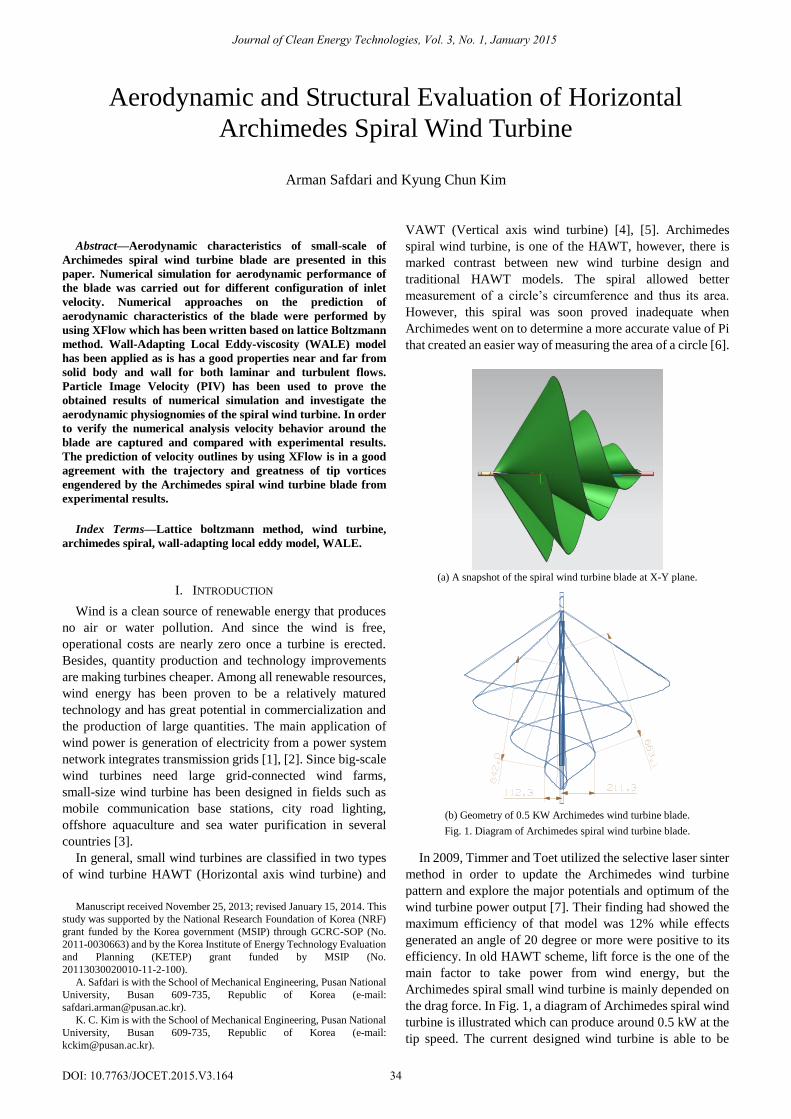
(a) A snapshot of the spiral wind turbine blade at X-Y plane.
(b) Geometry of 0.5 KW Archimedes wind turbine blade.
Fig. 1. Diagram of Archimedes spiral wind turbine blade.
In 2009, Timmer and Toet utilized the selective laser sinter
method in order to update the Archimedes wind turbine
pattern and explore the major potentials and optimum of the
wind turbine power output [7]. Their finding had showed the
maximum efficiency of that model was 12% while effects
generated an angle of 20 degree or more were positive to its
efficiency. In old HAWT scheme, lift force is the one of the
main factor to take power from wind energy, but the
Archimedes spiral small wind turbine is mainly depended on
the drag force. In Fig. 1, a diagram of Archimedes spiral wind
turbine is illustrated which can produce around 0.5 kW at the
tip speed. The current designed wind turbine is able to be
Aerodynamic and Structural Evaluation of Horizontal
Archimedes Spiral Wind Turbine
Arman Safdari and Kyung Chun Kim
Journal of Clean Energy Technologies, Vol. 3, No. 1, January 2015
34DOI: 10.7763/JOCET.2015.V3.164

removing its kinetic energy by reversing wind direction. In the
present research, an experimental study is accompanied to
obtain evolution of the tip vortex structures in the near wake
of the Archimedes wind turbine model and the aerodynamic
characteristics in an open type wind tunnel by using a PIV
measurement system. The Lattice Boltzmann method has
been applied to investigate the behavior of aerodynamic
characteristics surrounding the Archimedes wind turbine and
test the capability as a design implement for the wind turbine.
The focus of this research is on quantifying the evolution of
the tip vortex properties and velocity distributions, including
mean velocities and instantaneous velocities. This research
will let us understand deeply on the turbulent wake structures.
II. NUMERICAL
Lattice Boltzmann Method (LBM) schemes have been
intensively studied in recent years being their affinity to the
computational calculation their main advantage. XFlow is one
of the analysis programs for engineering analysis which it
uses a proprietary, particle-based, fully Lagrangian approach
by using LBM in order to simulate complex problems such as
aerodynamics, aero-acoustics, moving parts and
fluid-structure interaction. LBM is proposed on one
distribution function which is applied for the momentum
equation. Macroscopic fluid quantities such as velocity and
pressure are obtained by solving the momentum equation. For
the incompressible problems are computed by the following
equations [8]:
i
eq
i
BGK
i ff
1 (1)
where the f (distribution function) has been utilized to
compute the velocity and density fields and represents the
relaxation time for the flow. The eqf in Eq. 1 is the
equilibrium distribution function for density. Usually the
discretized equilibrium distribution function for D3Q19
adopts the following expression [9]:
)(
2
11
22
2
2
s
ii
s
i
s
ii
eq
ic
cc
c
uc
c
ucf (2)
where cs is the sound speed, u the macroscopic velocity, δ the
Kronecker delta, andi are built preserving the isotropy. Fig.
2 shows that a domain established at preparation phase
including flow domain in order to compute the shape of blade
on XFlow. In 3D lattice Boltzmann method, the physical
space is discretized into uniform Cartesian cells. Each node in
the lattice units is related to its neighbors over a number of
lattice velocities that are to be determined for different pattern
of LBM.
In this purpose, the D3Q19 scheme has been implemented
and The Wall-Adapting Local Eddy-viscosity (WALE) model
has been selected which has good properties both near to and
far from the wall and both for laminar and turbulent flows [10],
[11]. This model recovers the asymptotic behavior of the
turbulent boundary layer when this layer can be directly
solved and it does not add artificial turbulent viscosity in the
shear regions out of the wake. The WALE model is
formulated as follows:
31
222
4525
23
2
3
1
2
1
2
1
VolC
rg
gggG
rrS
GGSS
GG
w
d
dd
dd
turbulent
(3)
where the WALE constant (Cw) was set at 0.325.
For obtaining accurate result the element number was about
3,000,000 lattice cells on static domain which are shown in
Fig. 2. In this simulation, we chose three cases to predict the
aerodynamic characteristics with various inlet wind velocity
which are 3.5m/s, 4m/s and 4.5m/s; and rotating velocity was
selected at 300rpm, 400rpm and 500rpm, respectively.
Fig. 2. Cell configuration of the wind turbine.
III. EXPERIMENTAL
Fig. 3 illustrates the diagram of experimental structure for
PIV measurement. The 1/10 down scaled experimental model
based on the Archimedes screw was engaged to gain detailed
flow information. The PIV system was utilized in order to
measure the 2D velocity component plane from horizontal
stream-wise (x-y plane). The laser beam illuminated from U
wave mini-YAG laser was transformed into a light sheet
through cylindrical and spherical lenses. The field of view for
velocity field measurement is about 150 mm*120 mm
corresponding to the CCD resolution of 1280*1024 pixels.
Fig. 3. Experimental setup for PIV measurement.
A digital 12bit CCD camera (PCO Sensicam qe camera)
was setup vertically under the Archimedes wind turbine to
Journal of Clean Energy Technologies, Vol. 3, No. 1, January 2015
35
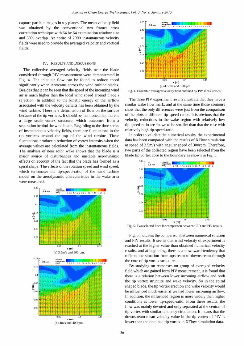
capture particle images in x-y planes. The mean velocity field
was obtained by the conventional two frames cross
correlation technique with 64 by 64 examination window size
and 50% overlap. An entire of 2000 instantaneous velocity
fields were used to provide the averaged velocity and vortical
fields.
IV. RESULTS AND DISCUSSIONS
The collective averaged velocity fields near the blade
considered through PIV measurement were demonstrated in
Fig. 4. The inlet air flow can be found to reduce speed
significantly when it streams across the wind turbine blades.
Besides that it can be seen that the speed of the incoming wind
air is much higher than the local wind speed around blade’s
rejection. In addition to the kinetic energy of the airflow
associated with the velocity deficits has been obtained by the
wind turbine. There is a deformation of flow on the surface
because of the tip vortices. It should be mentioned that there is
a large scale vortex structure, which outcomes from a
separation behind the wind blade. Regarding to the time series
of instantaneous velocity fields, there are fluctuations in the
tip vortices around the top of the wind turbine. These
fluctuations produce a reduction of vortex intensity when the
average values are calculated from the instantaneous fields.
The analysis of near rotor wake shows that the blade is a
major source of disturbances and unstable aerodynamic
effects on account of the fact that the blade has formed as a
spiral shape. The effects of the rotation speed and wind speed,
which terminates the tip-speed-ratio, of the wind turbine
model on the aerodynamic characteristics in the wake area
were measured.
(a) 3.5m/s and 300rpm.
(b) 4m/s and 400rpm.
(c) 4.5m/s and 500rpm
Fig. 4. Ensemble averaged velocity field obtained by PIV measurement.
The three PIV experiment results illustrate that they have a
similar wake flow mark, and at the same time those contours
show that the only differences were just from the comparison
of the plots at different tip-speed-ratios. It is obvious that the
velocity reductions in the wake region with relatively low
tip-speed-ratio are shown to be smaller than that the case with
relatively high tip-speed-ratio.
In order to validate the numerical results, the experimental
data has been compared with the results of XFlow simulation
at speed of 3.5m/s with angular speed of 300rpm. Therefore,
two parts of the collected region have been selected from the
blade tip vortex core to the boundary as shown in Fig. 5.
Fig. 5. Two selected lines for comparison between CFD and PIV results.
Fig. 6 indicates the comparison between numerical solution
and PIV results. It seems that wind velocity of experiment is
reached at the higher value than obtained numerical velocity
results, and at beginning, there is a downward tendency that
reflects the situation from upstream to downstream through
the core of tip vortex structure.
By studying on responses on group of averaged velocity
field which are gained form PIV measurement, it is found that
there is a relation between lower incoming airflow and both
the tip vortex structure and wake velocity. So in the spiral
shaped blade, the tip vortex erection and wake velocity would
be influenced much easier if we had lower incoming airflow.
In addition, the influenced region is more widely than higher
conditions at lower tip-speed-ratio. From these results, the
flow was mainly devoted and only separated at the central of
tip vortex with similar tendency circulation. It means that the
downstream mean velocity value in the tip vortex of PIV is
lower than the obtained tip vortex in XFlow simulation data.
Journal of Clean Energy Technologies, Vol. 3, No. 1, January 2015
36
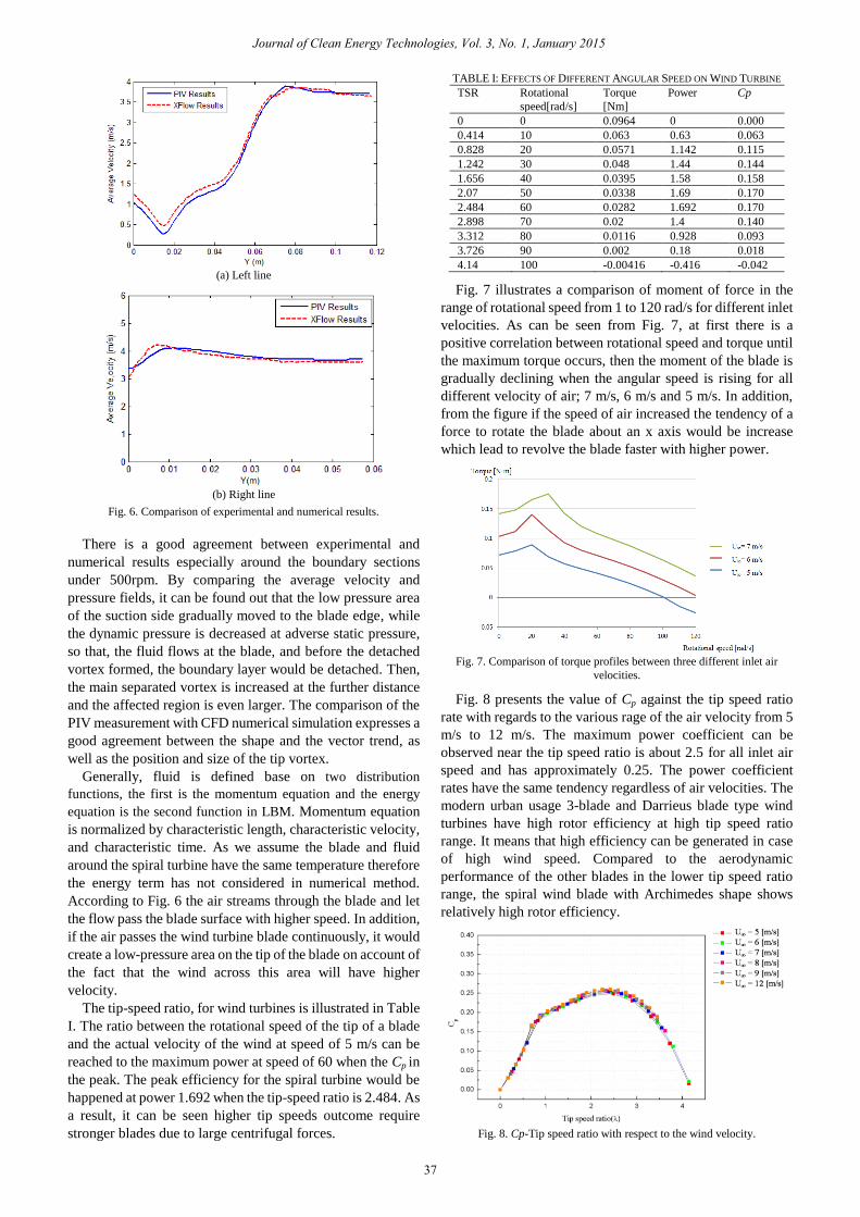
(a) Left line
(b) Right line
Fig. 6. Comparison of experimental and numerical results.
There is a good agreement between experimental and
numerical results especially around the boundary sections
under 500rpm. By comparing the average velocity and
pressure fields, it can be found out that the low pressure area
of the suction side gradually moved to the blade edge, while
the dynamic pressure is decreased at adverse static pressure,
so that, the fluid flows at the blade, and before the detached
vortex formed, the boundary layer would be detached. Then,
the main separated vortex is increased at the further distance
and the affected region is even larger. The comparison of the
PIV measurement with CFD numerical simulation expresses a
good agreement between the shape and the vector trend, as
well as the position and size of the tip vortex.
Generally, fluid is defined base on two distribution
functions, the first is the momentum equation and the energy
equation is the second function in LBM. Momentum equation
is normalized by characteristic length, characteristic velocity,
and characteristic time. As we assume the blade and fluid
around the spiral turbine have the same temperature therefore
the energy term has not considered in numerical method.
According to Fig. 6 the air streams through the blade and let
the flow pass the blade surface with higher speed. In addition,
if the air passes the wind turbine blade continuously, it would
create a low-pressure area on the tip of the blade on account of
the fact that the wind across this area will have higher
velocity.
The tip-speed ratio, for wind turbines is illustrated in Table
I. The ratio between the rotational speed of the tip of a blade
and the actual velocity of the wind at speed of 5 m/s can be
reached to the maximum power at speed of 60 when the Cp in
the peak. The peak efficiency for the spiral turbine would be
happened at power 1.692 when the tip-speed ratio is 2.484. As
a result, it can be seen higher tip speeds outcome require
stronger blades due to large centrifugal forces.
TABLE I: EFFECTS OF DIFFERENT ANGULAR SPEED ON WIND TURBINE
TSR Rotational
speed[rad/s]
Torque
[Nm]
Power Cp
0 0 0.0964 0 0.000
0.414 10 0.063 0.63 0.063
0.828 20 0.0571 1.142 0.115
1.242 30 0.048 1.44 0.144
1.656 40 0.0395 1.58 0.158
2.07 50 0.0338 1.69 0.170
2.484 60 0.0282 1.692 0.170
2.898 70 0.02 1.4 0.140
3.312 80 0.0116 0.928 0.093
3.726 90 0.002 0.18 0.018
4.14 100 -0.00416 -0.416 -0.042
Fig. 7 illustrates a comparison of moment of force in the
range of rotational speed from 1 to 120 rad/s for different inlet
velocities. As can be seen from Fig. 7, at first there is a
positive correlation between rotational speed and torque until
the maximum torque occurs, then the moment of the blade is
gradually declining when the angular speed is rising for all
different velocity of air; 7 m/s, 6 m/s and 5 m/s. In addition,
from the figure if the speed of air increased the tendency of a
force to rotate the blade about an x axis would be increase
which lead to revolve the blade faster with higher power.
Fig. 7. Comparison of torque profiles between three different inlet air
velocities.
Fig. 8 presents the value of Cp against the tip speed ratio
rate with regards to the various rage of the air velocity from 5
m/s to 12 m/s. The maximum power coefficient can be
observed near the tip speed ratio is about 2.5 for all inlet air
speed and has approximately 0.25. The power coefficient
rates have the same tendency regardless of air velocities. The
modern urban usage 3-blade and Darrieus blade type wind
turbines have high rotor efficiency at high tip speed ratio
range. It means that high efficiency can be generated in case
of high wind speed. Compared to the aerodynamic
performance of the other blades in the lower tip speed ratio
range, the spiral wind blade with Archimedes shape shows
relatively high rotor efficiency.
Fig. 8. Cp-Tip speed ratio with respect to the wind velocity.
Journal of Clean Energy Technologies, Vol. 3, No. 1, January 2015
37

In addition, the blade had high Cp values in a wider range of
the tip speed ratio. Regarding to the total aerodynamic
characteristics, it can be concluded that the Archimedes spiral
turbine is appropriate design for using urban wind.
V. CONCLUSION
In this study, the PIV technique and numerical methods
were performed to study the behavior of the flow around the
turbine and efficiency power near the wake of the Archimedes
spiral wind turbine blade. As results, our gained finding can
be summarized as follows:
1) The rotational speed of the blade is directly influenced
base on the speed of inlet air. In addition, our
investigation demonstrated the blade can be reach at
angular speed around 500rpm while the inlet velocity is
4.5m/s.
2) The inner low speed section rotated the same turning
direction of the blade. The relative velocity of the flow is
closed zero to the blade.
3) The investigation of the obtained results determined the
straight interaction between the mean flow at the rotor
downstream and the induced velocity due to the tip
vortices.
4) The finding exposed the presence of important vortex
constructions downstream the hub and near the root of
the blade. Some unpredictability of the helical tip
vortices is also distinguished. Because of these
fluctuations, the instantaneous velocity field is very rich
with the evidences.
5) The maximum efficiency for the spiral turbine would be
happened when the Cp is in the peak.
6) Numerical simulation results have a good agreement with
the PIV experiments.
7) Regarding to the PIV experiment, the provided
information of the blade flow for different wind velocity
of attack are helpful to improve the performance and the
design of Archimedes spiral wind turbine.
REFERENCES
[1] Small Wind World Report Summary 2012, World Wind Energy
Association, 2012
[2] A. A. Edward and B. W. Philip, “The effect of wind on energy
consumption in buildings,” Energy and Buildings, vol. 1, no. 1, pp.
77-84, 1977.
[3] Renewable Energy Policy Network for the 21st Century, Renewables
2011 Global Status Report, 2011.
[4] H. Cao, “Aerodynamics analysis of small horizontal axis wind turbine
blades by using 2D and 3D CFD modeling”, M.S. thesis, University of
the Central Lancashire, 2011.
[5] N. J. Choi, S. H. Nam, J. H. Jeong, and K. C. Kim, “Numerical study on
the horizontal axis turbines arrangement in a wind farm: Effect of
separation distance on the turbine aerodynamic power output,”
Journal of Wind Engineering and Industrial Aerodynamics, vol. 117,
pp. 11-17, 2013.
[6] W. A. Timmer and S. Toet, “Verslag van de metingen aan de
archimedes in de lage-snelheids windtunnel van dnw”. TU Delft, 2009.
[7] Q. Lu, Q. Li, Y. K. Kim and K. C. Kim, “A study on design and
aerodynamic characteristics of a spiral-type wind turbine blade,”
Journal of KSV, vol. 10, no. 1, pp. 27-33, 2012.
[8] Y. H. Qian, D. d’Humieres, and P. Lallemand, “Lattice BGK models
for NavierStokes equation,” EPL (Europhysics Letters), vol. 17, no. 6,
pp. 479, 1992.
[9] C. S. Michael and T. T. Jr. Daniel, Lattice Boltzmann Modeling: An
Introduction for Geoscientists and Engineer, 1st ed. Spring, 2006, ch.
4, pp. 34-54.
[10] M. Weickert, G. Teike, O. Schmidt, and M. Sommerfeld,
“Investigation of the LES WALE turbulence model within the lattice
Boltzmann framework,” Computers & Mathematics with Applications,
vol. 5, pp. 2200-2214, 2010.
[11] C. S. Zhuo and C. W. Zhong, “LES-based filter-matrix lattice
Boltzmann model for simulating turbulent natural convection in a
square cavity,” International Journal of Heat and Fluid Flow, vol. 42,
pp. 10-22, 2013.
Arman Safdari received master degree in mechanical
engineering from Technical University of Malaysia in
2012. Currently he is a postgraduate student at the
Faculty of Mechanical Engineering, Pusan National
University.
His current research interests include simulation
and modeling of fluid flow, flow structure interaction,
renewable Energy, heat transfer, numerical methods
and advanced engineering mathematics theory.
Kyung Chun Kim is a professor in the School of
Mechanical Engineering of Pusan National
University. He obtained his Ph.D. degree from the
Korea Advanced Institute of Science and Technology
(KAIST), Korea, in 1987.
His research interests include multi-scale
multi-physics measurements, such as micro-PIV/LIF,
bio-MEMS, design and fabrication of thermal
management system, organic Rankine cycle,
renewable energy, etc.
Journal of Clean Energy Technologies, Vol. 3, No. 1, January 2015
38