Embed Size (px)
Citation preview
Aerodynamic analysis of flow field around typical re-entry capsule at supersonic speed
K.Ajith Kumar
Department of Aeronautical Engineering Parisutham Institute of Technology and Science, Thanjavur, Tamil Nadu, India
J.Ajmal Thahaseen
Department of Aeronautical Engineering Parisutham Institute of Technology and Science, Thanjavur, Tamil Nadu, India
K.Nija Bharathi
Department of Aeronautical Engineering Parisutham Institute of Technology and Science, Thanjavur, Tamil Nadu, India
W.Melvin Raj
Department of Aeronautical Engineering Parisutham Institute of Technology and Science, Thanjavur, Tamil Nadu, India
Abstract- Aerodynamics analysis over re-entry capsule may include atmospheric entries at very high velocities with highly radiative constituents. In this project, two cases of re-entry capsule with thermal protection system have taken for analysis. One without using flaps and the other with using four flaps. Flow field around both cases of capsule has been investigated adopting three dimensional computational fluid dynamic analysis by using CFD software tool packages (ICEM CFD, CFX-Pre-processor, solver, Post processor) and adopting k- Epsilon turbulence model to study the effects of flow separation through the bow shock wave and expansion shock wave over the capsule in supersonic boundary layer condition at Mach number 3. Comparative studies of flow fluctuations effect and stability of the re-entry capsule for both cases has been studied. It is observed that the re-entry capsule with flaps has given the better aerodynamic performances and stability characteristics
Keywords – Re-entry capsule, CFD, Flaps, Shock wave.
I. INTRODUCTION
Atmospheric entry is the movement of an object into and through the gases of a planet's atmosphere from outer space. There are two main types of atmospheric entry - uncontrolled entry, such as in the entry of celestial objects, space debris or bolides - and controlled entry, such as the entry (or re-entry) of technology capable of being navigated or following a predetermined course. Atmospheric drag and aerodynamic heating can cause atmospheric break up capable of completely disintegrating smaller objects. These forces may cause objects with lower compressive strength to explode. For Earth, atmospheric entry occurs above the Karman Line at an altitude of more than 100 km above the surface while Venus atmospheric entry occurs at 250 km and Mars atmospheric entry at about 80 km. Uncontrolled, objects accelerate through the atmosphere at extreme velocities under the influence of Earth's gravity. Most controlled objects enter at hypersonic speeds due to their suborbital (e.g., ICBM reentry vehicles), orbital (e.g., the Space Shuttle), or unbounded (e.g., meteors) trajectories. Various advanced technologies have been developed to enable atmospheric re-entry and flight at extreme velocities. An alternative low velocity method of controlled atmospheric entry is buoyancy[1] which is suitable for planetary entry where thick atmospheres, strong gravity or both factors complicate high velocity hyperbolic entry, such as the atmospheres of Venus, Titan and the gas giants
International Journal of Latest Transactions in Engineering and Science
Volume 2 Issue 1- March 2017 6 ISSN: 2321-0605
II. ICEM CFD GEOMETRY AND MESH REPORT
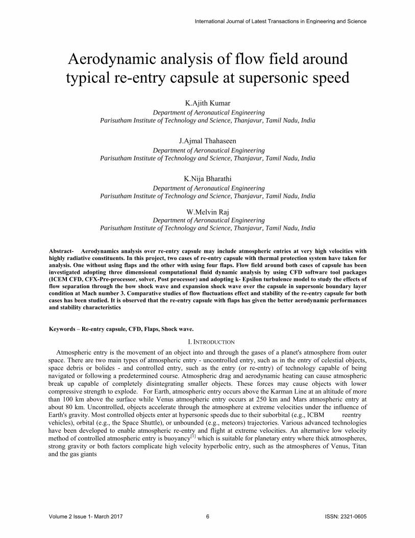
The geometry of the re-entry capsule is quite complex and the solid modeling is carried by ICEM CFD modeling tools. The dimensions are taken for the re-entry capsule as from the base paper. The solid model was drawn in ICEM CFD by the help of design parameters of the re-entry capsule will be shown in following tables. The model of the reentry capsule is modified slightly to do the flow analysis. Here the analysis the flow over the re-entry capsule so requires the flow domain for the flow analysis. Therefore for flow analysis, a flow domain is created as for the dimensions required. Here creating the cylindrical shape domain with diameter 3L and length 8L.where L is the length of the re-entry capsule. Before starting the mesh need to create the boundary layer around the re-entry capsule body. And then mesh the faces of the body by using unstructured mesh. To create 3D mesh of the domain the trihedral pave elements are used. Check the mesh of the domain for convergence. In this the flow domain selected as AIR for Outer region and SOLID for reentry capsule region. And the flow boundary is selected as INLET, OUTLET, and OUTER WALL for the outer region and WALL for the re-entry capsule. The basic geometry, domain structure, meshed structured will be shown in following figures. For our aerodynamic analysis, we are taking two cases of capsules shapes and corresponding design parameters are taken from base paper. And their parameters will be shown in table. Two cases:
1. Existing system (Re-entry capsule designed without flaps) 2. Proposing system (Re-entry capsule designed with 4 flaps)
CASE 1) Existing system (Re-entry capsule designed without flaps)
Table 1.Model configuration of case1
MODEL CONFIGURATION DIMENSION
Total height 1600 mm
Spheric Diameter 560 mm
Nose angle 15°
Frusted cone slant height 280mm
Frusted edge length 525mm
Blunt body radius 330mm
Total length 1050mm Angle of Attack 0⁰
Herewith, we are following the steps involved in methodology, first we draw the geometrical diagram which taken dimensions from the design configuration table. And converting the geometrical diagram into three dimensional objects in ICEM CFD.
Fig 1. Domain Structure Of Case 1 Capsule
Fig 2. Meshed Structure Of Case 1 Capsule
International Journal of Latest Transactions in Engineering and Science
Volume 2 Issue 1- March 2017 7 ISSN: 2321-0605
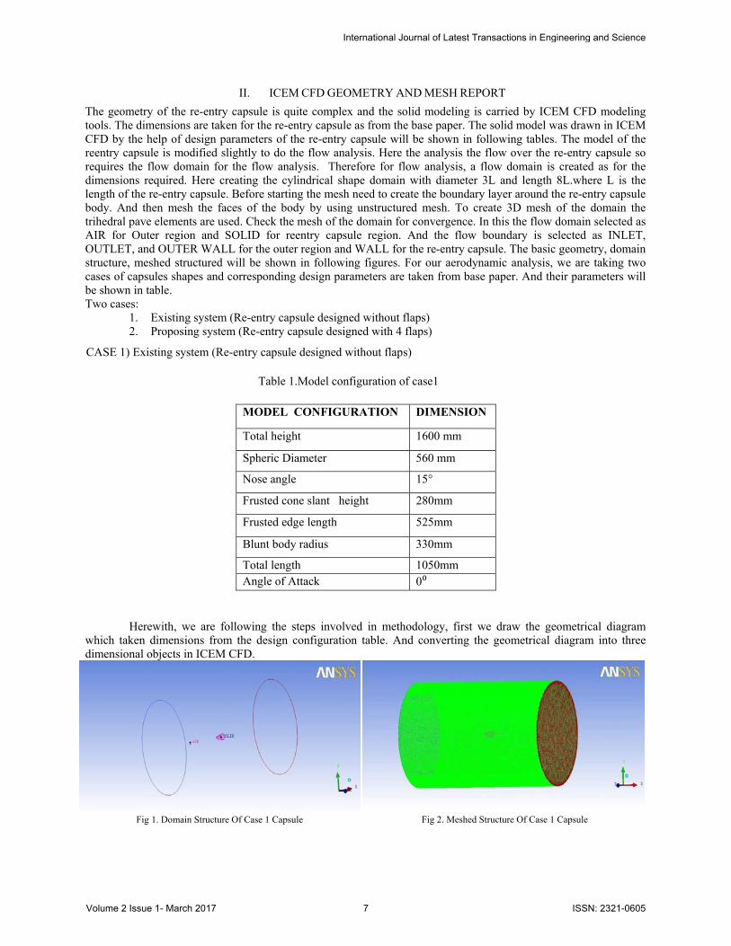
Defining the domain with above mentioned dimension which surrounding the capsule which call as air domain and inside capsule which call as solid as shown in following figures. After using unstructured mesh generates with trihedral, we have to convert the cylindrical domain into the meshed structure and get corresponding elements and nodes from the meshed parts as shown in following tables.
Furthermore, we will have to show the design geometry which we get from base paper with their configuration and appropriate domain and mesh diagram which we have got from ICEM CFD. Subsequently, we have got the meshed structure; the file is imported to cfx-pre in that we have to apply all boundary conditions values by using k-epsilon turbulence tool to study the turbulence effects over the capsule which is covered by high ablative material for heat resistance. Here, we have got the subsequent meshed details from the software and mentioned in the following table.
Table 2. Mesh Information for Case 1 Capsule
Domain Nodes Element
Air 85420 423514
Solid 32564 154628
All domain 117984 578142
CASE 2) Proposing system (Re-entry capsule designed with 4 flaps)
Table 3. Model configuration of case2
MODEL CONFIGURATION DIMENSION
Total height 1600 mm
Spheric Diameter 560 mm
Nose angle 15°
Frusted cone slant height 280 mm
Frusted edge length 525 mm
Blunt body radius 330 mm
Total length 1050 mm
Angle of Attack 0⁰ Area of the flap 400x300 mm
Flap angle 22⁰
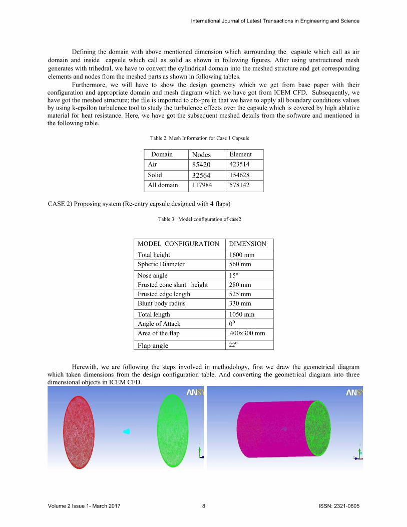
Herewith, we are following the steps involved in methodology, first we draw the geometrical diagram which taken dimensions from the design configuration table. And converting the geometrical diagram into three dimensional objects in ICEM CFD.
International Journal of Latest Transactions in Engineering and Science
Volume 2 Issue 1- March 2017 8 ISSN: 2321-0605
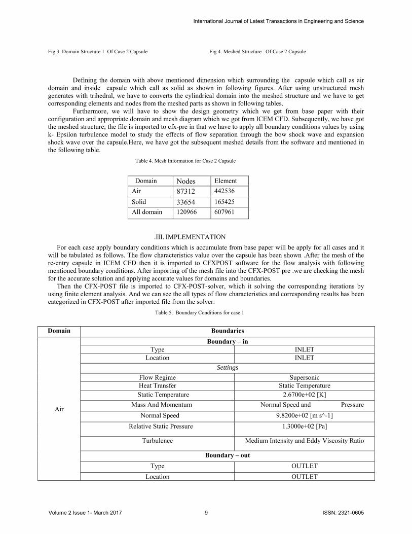
Fig 3. Domain Structure 1 Of Case 2 Capsule
Fig 4. Meshed Structure Of Case 2 Capsule
Defining the domain with above mentioned dimension which surrounding the capsule which call as air
domain and inside capsule which call as solid as shown in following figures. After using unstructured mesh generates with trihedral, we have to converts the cylindrical domain into the meshed structure and we have to get corresponding elements and nodes from the meshed parts as shown in following tables.
Furthermore, we will have to show the design geometry which we get from base paper with their configuration and appropriate domain and mesh diagram which we got from ICEM CFD. Subsequently, we have got the meshed structure; the file is imported to cfx-pre in that we have to apply all boundary conditions values by using k- Epsilon turbulence model to study the effects of flow separation through the bow shock wave and expansion shock wave over the capsule.Here, we have got the subsequent meshed details from the software and mentioned in the following table.
Table 4. Mesh Information for Case 2 Capsule
Domain Nodes Element
Air 87312 442536
Solid 33654 165425
All domain 120966 607961
.III. IMPLEMENTATION
For each case apply boundary conditions which is accumulate from base paper will be apply for all cases and it will be tabulated as follows. The flow characteristics value over the capsule has been shown .After the mesh of the re-entry capsule in ICEM CFD then it is imported to CFXPOST software for the flow analysis with following mentioned boundary conditions. After importing of the mesh file into the CFX-POST pre .we are checking the mesh for the accurate solution and applying accurate values for domains and boundaries.
Then the CFX-POST file is imported to CFX-POST-solver, which it solving the corresponding iterations by using finite element analysis. And we can see the all types of flow characteristics and corresponding results has been categorized in CFX-POST after imported file from the solver.
Table 5. Boundary Conditions for case 1
Domain Boundaries
Air
Boundary – inType INLET
Location INLET
Settings
Flow Regime Supersonic Heat Transfer Static Temperature
Static Temperature 2.6700e+02 [K]
Mass And Momentum Normal Speed and Pressure
Normal Speed 9.8200e+02 [m s^-1]
Relative Static Pressure 1.3000e+02 [Pa]
Turbulence Medium Intensity and Eddy Viscosity Ratio
Boundary – out
Type OUTLET
Location OUTLET
International Journal of Latest Transactions in Engineering and Science
Volume 2 Issue 1- March 2017 9 ISSN: 2321-0605
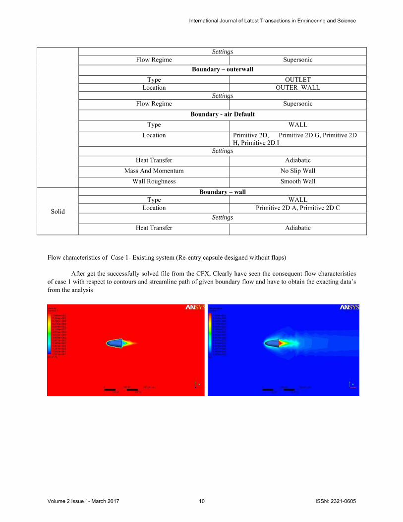
Flow characteristics of Case 1- Existing system (Re-entry capsule designed without flaps)
After get the successfully solved file from the CFX, Clearly have seen the consequent flow characteristics of case 1 with respect to contours and streamline path of given boundary flow and have to obtain the exacting data’s from the analysis
Settings Flow Regime Supersonic
Boundary – outerwall
Type OUTLET Location OUTER_WALL
Settings Flow Regime Supersonic
Boundary - air Default
Type WALL
Location Primitive 2D, Primitive 2D G, Primitive 2D H, Primitive 2D I
Settings
Heat Transfer Adiabatic
Mass And Momentum No Slip Wall
Wall Roughness Smooth Wall
Solid
Boundary – wallType WALL
Location Primitive 2D A, Primitive 2D C
Settings
Heat Transfer Adiabatic
International Journal of Latest Transactions in Engineering and Science
Volume 2 Issue 1- March 2017 10 ISSN: 2321-0605
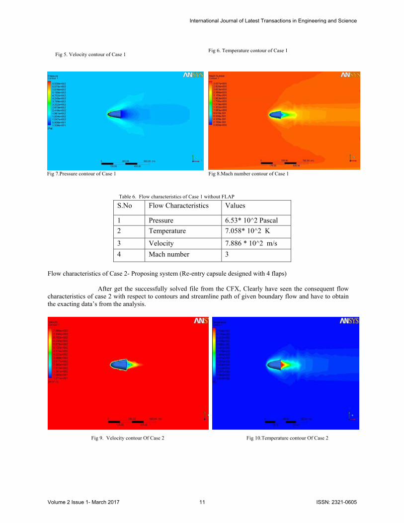
Fig 5. Velocity contour of Case 1 Fig 6. Temperature contour of Case 1
Fig 7.Pressure contour of Case 1 Fig 8.Mach number contour of Case 1
Table 6. Flow characteristics of Case 1 without FLAP
S.No Flow Characteristics Values
1 Pressure 6.53* 10^2 Pascal
2 Temperature 7.058* 10^2 K
3 Velocity 7.886 * 10^2 m/s
4 Mach number 3
Flow characteristics of Case 2- Proposing system (Re-entry capsule designed with 4 flaps)
After get the successfully solved file from the CFX, Clearly have seen the consequent flow characteristics of case 2 with respect to contours and streamline path of given boundary flow and have to obtain the exacting data’s from the analysis.
Fig 9. Velocity contour Of Case 2 Fig 10.Temperature contour Of Case 2
International Journal of Latest Transactions in Engineering and Science
Volume 2 Issue 1- March 2017 11 ISSN: 2321-0605
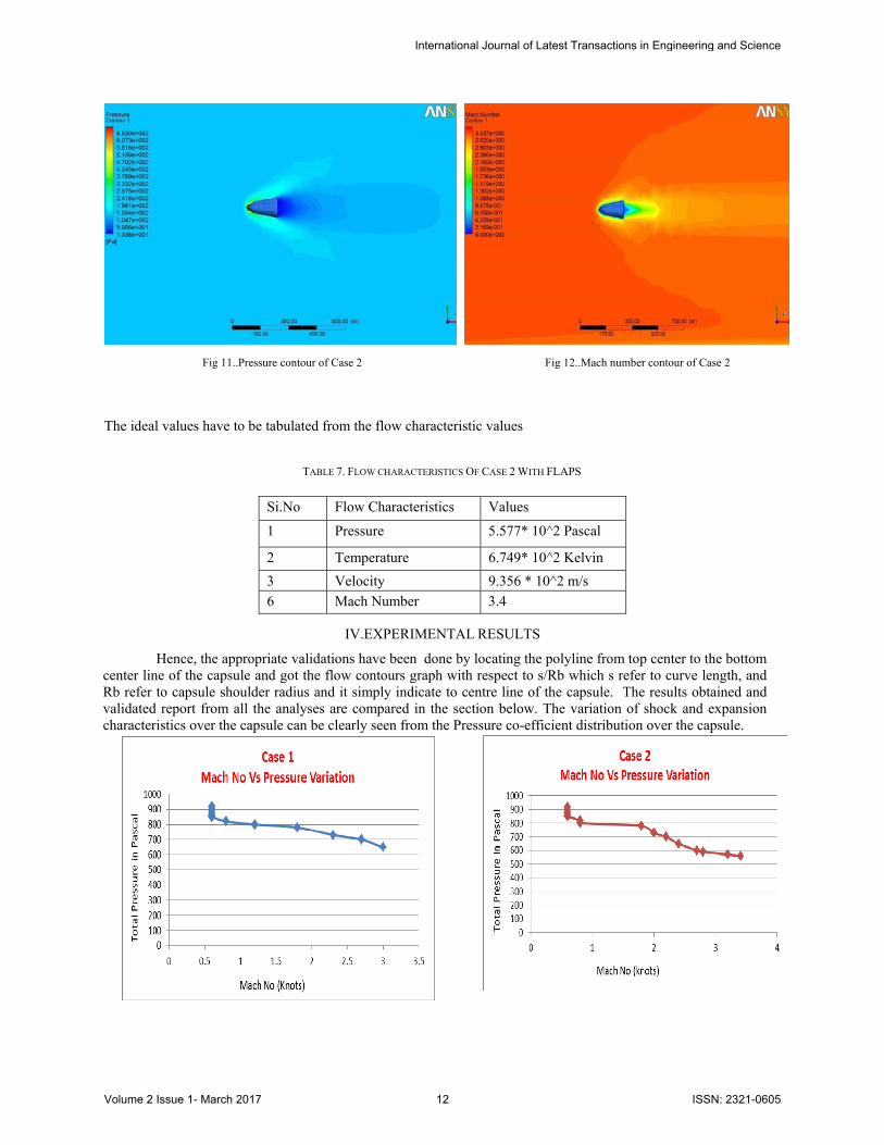
Fig 11..Pressure contour of Case 2 Fig 12..Mach number contour of Case 2
The ideal values have to be tabulated from the flow characteristic values
TABLE 7. FLOW CHARACTERISTICS OF CASE 2 WITH FLAPS
Si.No Flow Characteristics Values
1 Pressure 5.577* 10^2 Pascal
2 Temperature 6.749* 10^2 Kelvin
3 Velocity 9.356 * 10^2 m/s
6 Mach Number 3.4
IV.EXPERIMENTAL RESULTS
Hence, the appropriate validations have been done by locating the polyline from top center to the bottom center line of the capsule and got the flow contours graph with respect to s/Rb which s refer to curve length, and Rb refer to capsule shoulder radius and it simply indicate to centre line of the capsule. The results obtained and validated report from all the analyses are compared in the section below. The variation of shock and expansion characteristics over the capsule can be clearly seen from the Pressure co-efficient distribution over the capsule.
International Journal of Latest Transactions in Engineering and Science
Volume 2 Issue 1- March 2017 12 ISSN: 2321-0605
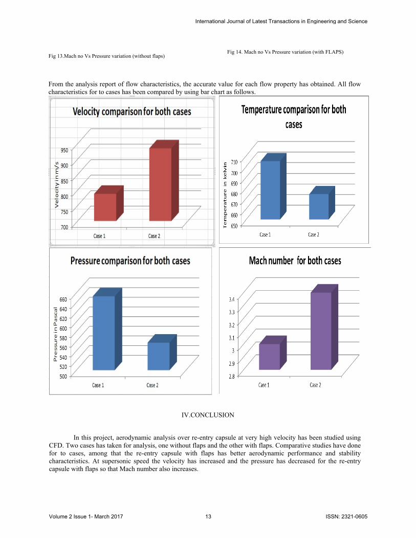
Fig 13.Mach no Vs Pressure variation (without flaps) Fig 14. Mach no Vs Pressure variation (with FLAPS)
From the analysis report of flow characteristics, the accurate value for each flow property has obtained. All flow characteristics for to cases has been compared by using bar chart as follows.
IV.CONCLUSION
In this project, aerodynamic analysis over re-entry capsule at very high velocity has been studied using
CFD. Two cases has taken for analysis, one without flaps and the other with flaps. Comparative studies have done for to cases, among that the re-entry capsule with flaps has better aerodynamic performance and stability characteristics. At supersonic speed the velocity has increased and the pressure has decreased for the re-entry capsule with flaps so that Mach number also increases.
International Journal of Latest Transactions in Engineering and Science
Volume 2 Issue 1- March 2017 13 ISSN: 2321-0605
REFERENCES [1] DR.B.BALAKRISHNA , S. VENKATESWARLU , DR P. RAVINDER REDDY “FLOW ANALYSIS OF AN ATMOSPHERE REENTRY VEHICLE “,PP.52-
57,2012 [2] Shiva Prasad U., Srinivas G. “Flow Simulation over Re-Entry Bodies at Supersonic & Hypersonic Speeds “PP. 29-34 (July 2012) [3] T. Rösgen , C. Pereira, S. Airaghi and A. Vuilleumier “Temperature Mapping of a Re-entry Vehicle Flap in High Enthalpy Flow Test “11th
International conference on Quantitative InfraRed Thermography conducted by QIRT 2012. [4] Baiocco P., Guedron S., Plotard P., Moulin J., “The Pre-X Atmospheric Re-entry Experimental Lifting Body: Program Status and System
Synthesis”, 57th IAC Congress, Valencia, Spain, 2-6 October 2006. [5] Tumino G., Gerard Y., “Europe among the World Players in Atmospheric Reentry”, ESA bulletin 128, November 2006. [6] Oswald J. et al., “DLR-ONERA accurate CFD support to the Pre-X project”, 6th International Symposium on Launchers Technologies,
Munich, Germany, 8-11 November 2005. [7] Marini M., “Body-Flap Efficiency Prediction of a FESTIP Concept Vehicle”, Second International Symposium on Atmospheric Reentry
Vehicles and Systems, Arcachon, France, March 26-29, 2001. [8] Roncioni P., Ranuzzi G., Marini M., “FLPP-IXV Project – Phase B1.2 – Preliminary CFD Activities Synthesis Report”, CIRA Internal
Report, CIRA-CF-07-0223, March 2007. [9] Ranuzzi G., Borreca S., “CLAE Project. H3NS: Code Development Verification and Validation”, CIRA internal report. CIRA-CF-06-1017,
September 2006. [10] Whitmore S., Dunbar B., “Orbital Space Plane, Past, Present, and Future”. AIAA International Air and Space Symposium: The Next 100
Years, Dayton, Ohio, July 14-17, 2003. AIAA-2003-2718.
International Journal of Latest Transactions in Engineering and Science
Volume 2 Issue 1- March 2017 14 ISSN: 2321-0605