Embed Size (px)
Citation preview
ADDENDUM
USER'S GUIDE FOR THE
AMS/EPA REGULATORY MODEL - AERMOD
(EPA-454/B-03-001, September 2004)
U.S. ENVIRONMENTAL PROTECTION AGENCY Office of Air Quality Planning and Standards
Air Quality Assessment Division Research Triangle Park, North Carolina 27711
December 2006
ii
ACKNOWLEDGEMENTS
Portions of this Addendum to the “User’s Guide for the AMS/EPA Regulatory Model –
AERMOD” related to the PSDCREDIT option for the Plume Volume Molar Ratio Method
(PVMRM) were prepared by MACTEC Federal Programs, Inc., Research Triangle Park, North
Carolina. This effort was funded by the Environmental Protection Agency, Region 10, under
Contract No. EP-D-05-096, with Herman Wong as the Work Assignment Manager (WAM).
iii
CONTENTS 1.0 INTRODUCTION................................................................................................................... 1
1.1 OVERVIEW OF AERMOD REVISIONS ....................................................................... 1 1.2 BACKGROUND ON DEPOSITION ALGORITHMS ................................................... 2
2.0 USER INSTRUCTIONS ........................................................................................................ 3
2.1 DISPERSION MODELING OPTIONS ........................................................................... 3 2.1.1 MODELOPT Keyword.................................................................................................. 3 2.1.2 BETA Test Options........................................................................................................ 4 2.1.3 Processing for Particulate Matter (PM) NAAQS .......................................................... 5
2.1.3.1 Processing for Fine Particulate Matter (PM-2.5).................................................... 5 2.1.3.2 Processing for Particulate Matter of 10 Microns or Less (PM-10) ........................ 7
2.1.4 Specifying Multiple Urban Areas .................................................................................. 8 2.1.5 BETA Options for Capped and Horizontal Stack Releases........................................... 9
2.2 DEPOSITION ALGORITHM INPUTS AND OPTIONS ............................................ 10 2.2.1 Definition of Seasons for Gas Dry Deposition ............................................................ 10 2.2.2 Definition of Land Use Categories for Gas Dry Deposition ....................................... 11 2.2.3 Option for Overriding Default Parameters for Gas Dry Deposition............................ 12 2.2.4 Specifying Source Parameters for Gas Deposition...................................................... 13 2.2.5 Specifying Source Parameters for Particle Deposition................................................ 13
2.2.5.1 Specifying Particle Inputs for Method 1............................................................... 14 2.2.5.2 Specifying Particle Inputs for Method 2............................................................... 15
2.2.6 Specifying Emission and Output Units........................................................................ 15 2.2.7 Deposition Velocity and Resistance Outputs............................................................... 16 2.2.8 Meteorological Data for Deposition Algorithms ......................................................... 16
2.3 OPEN PIT SOURCE OPTION ....................................................................................... 18 2.4 PVMRM AND OLM OPTIONS FOR MODELING NO2 ............................................ 20
2.4.1 Specifying Ozone Concentrations for PVMRM and OLM Options............................ 21 2.4.2 Specifying the Ambient Equilibrium NO2/NOx Ratio for PVMRM .......................... 22 2.4.3 Specifying the Default In-stack NO2/NOx Ratio for PVMRM and OLM.................. 22 2.4.4 Specifying In-stack NO2/NOx Ratios by Source for PVMRM and OLM .................. 23 2.4.5 Specifying Combined Plumes for OLM ...................................................................... 24 2.4.6 Modeling NO2 Increment Credits with PVMRM ....................................................... 25
2.4.6.1 Increment Consuming and Baseline Sources........................................................ 26 2.4.6.2 Calculating Increment Consumption under the PSDCREDIT Option ................. 26 2.4.6.3 Specifying Source Groups under the PSDCREDIT Option ................................. 29 2.4.6.4 Model Outputs under the PSDCREDIT Option ................................................... 30
2.5 VARIABLE EMISSION RATES .................................................................................... 31 2.6 ALLOCATABLE ARRAYS FOR AREAPOLY SOURCES........................................ 33
3.0 REFERENCES...................................................................................................................... 35 APPENDIX A EPA Model Clearinghouse Memorandum, Dated July 9, 1993 ................... 36
1
1.0 INTRODUCTION
1.1 OVERVIEW OF AERMOD REVISIONS
This document provides user instructions for revisions to the AERMOD dispersion
model. The discussion provided here supplements the information contained in the current
AERMOD User’s Guide (EPA, 2004a), and it is assumed that the reader is already familiar with
the contents of that document.
Three sets of AERMOD revisions are included in this Addendum:
1. The first set of revisions, first introduced with version 03273 of AERMOD, includes dry and wet deposition algorithms for both particulate and gaseous emissions, and the OPENPIT source option, originally incorporated in the ISCST3 model (EPA, 1995a), for modeling particulate emissions from open pit (below grade) sources, such as surface coal mines and rock quarries;
2. The second set of revisions, first introduced with version 04300 of AERMOD, includes two non-default options for modeling conversion of NOx to NO2: 1) the Plume Volume Molar Ratio Method (PVMRM) (Hanrahan, 1999a and 1999b); and 2) the Ozone Limiting Method (OLM); and
3. The third set of revisions, first introduced with version 06341 of AERMOD, includes the following:
a. A new “BETA” option on the CO MODELOPT card to allow for new features to be added to AERMOD that are still in BETA-test status;
b. A BETA option for incorporating NO/NO2 chemistry for NO2 increment consumption calculations with PSD credits using the PVMRM option;
c. BETA options for capped and horizontal stack releases;
d. An option to specify an initial default in-stack NO2/NOx ratio for the PVMRM and OLM options;
e. New options for varying emissions by month, hour-of-day, and day-of-week (MHRDOW and MHRDOW7);
f. An option to allow multiple urban areas to be defined in a single model run;
g. Updated processing to support modeling demonstrations for the National Ambient Air Quality Standards (NAAQS) for PM, including the 24-hour average design value for primary PM-2.5 impacts; and
2
h. Use of dynamic array allocation for AREAPOLY sources to allocate array limits for the maximum number of vertices at model runtime, replacing the previous fixed array limit of 20 vertices.
1.2 BACKGROUND ON DEPOSITION ALGORITHMS
The deposition algorithms are based on the draft Argonne National Laboratory (ANL)
report (Wesely, et. al., 2002), with modifications based on peer review. Treatment of wet
deposition is revised based on recommendations by peer review panel members (Walcek, et al.,
2001). A full technical description of the deposition algorithms implemented in AERMOD is
provided in an EPA report (EPA, 2003).
The deposition algorithms have been implemented in the AERMOD model under the
non-default TOXICS option, which is selected by including the TOXICS keyword on the CO
MODELOPT card (see Section 2.1.1). The other changes to the AERMOD model inputs
associated with the deposition algorithms are limited to the CO (control) pathway and the SO
(source) pathway. For gaseous deposition, the user must define the seasonal categories based on
the ANL report for each of the calendar months, and must also define the land use category and
three pollutant-specific physical parameters that are provided in the appendices of the ANL
report. An optional keyword is also provided to override default values for three parameters
used in the gas deposition algorithm. The input requirements for Method 1 particle deposition
are the same as for the non-TOXICS particle deposition algorithm in the ISCST3 model and are
described below. For Method 2 particle deposition, the user must define the fraction of the
particle mass in the fine particle category (less than 2.5 microns) and a representative mass mean
diameter for the particles, which are also provided for selected pollutants in Appendix B of the
ANL report. The keywords used to define these inputs and the meteorological data format are
described in Section 2.2.
3
2.0 USER INSTRUCTIONS
2.1 DISPERSION MODELING OPTIONS
2.1.1 MODELOPT Keyword
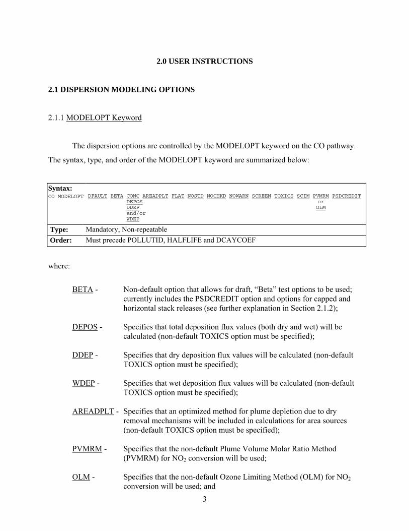
The dispersion options are controlled by the MODELOPT keyword on the CO pathway.
The syntax, type, and order of the MODELOPT keyword are summarized below:
Syntax: CO MODELOPT
DFAULT BETA CONC AREADPLT FLAT NOSTD NOCHKD NOWARN SCREEN TOXICS SCIM PVMRM PSDCREDIT DEPOS or DDEP OLM and/or WDEP
Type: Mandatory, Non-repeatable Order: Must precede POLLUTID, HALFLIFE and DCAYCOEF
where:
BETA - Non-default option that allows for draft, “Beta” test options to be used;
currently includes the PSDCREDIT option and options for capped and horizontal stack releases (see further explanation in Section 2.1.2);
DEPOS - Specifies that total deposition flux values (both dry and wet) will be
calculated (non-default TOXICS option must be specified); DDEP - Specifies that dry deposition flux values will be calculated (non-default
TOXICS option must be specified); WDEP - Specifies that wet deposition flux values will be calculated (non-default
TOXICS option must be specified); AREADPLT - Specifies that an optimized method for plume depletion due to dry
removal mechanisms will be included in calculations for area sources (non-default TOXICS option must be specified);
PVMRM - Specifies that the non-default Plume Volume Molar Ratio Method
(PVMRM) for NO2 conversion will be used; OLM - Specifies that the non-default Ozone Limiting Method (OLM) for NO2
conversion will be used; and
4
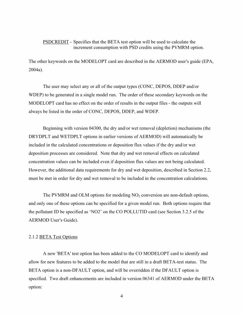
PSDCREDIT - Specifies that the BETA test option will be used to calculate the
increment consumption with PSD credits using the PVMRM option.
The other keywords on the MODELOPT card are described in the AERMOD user=s guide (EPA,
2004a).
The user may select any or all of the output types (CONC, DEPOS, DDEP and/or
WDEP) to be generated in a single model run. The order of these secondary keywords on the
MODELOPT card has no effect on the order of results in the output files - the outputs will
always be listed in the order of CONC, DEPOS, DDEP, and WDEP.
Beginning with version 04300, the dry and/or wet removal (depletion) mechanisms (the
DRYDPLT and WETDPLT options in earlier versions of AERMOD) will automatically be
included in the calculated concentrations or deposition flux values if the dry and/or wet
deposition processes are considered. Note that dry and wet removal effects on calculated
concentration values can be included even if deposition flux values are not being calculated.
However, the additional data requirements for dry and wet deposition, described in Section 2.2,
must be met in order for dry and wet removal to be included in the concentration calculations.
The PVMRM and OLM options for modeling NO2 conversion are non-default options,
and only one of these options can be specified for a given model run. Both options require that
the pollutant ID be specified as ‘NO2’ on the CO POLLUTID card (see Section 3.2.5 of the
AERMOD User=s Guide).
2.1.2 BETA Test Options
A new 'BETA' test option has been added to the CO MODELOPT card to identify and
allow for new features to be added to the model that are still in a draft BETA-test status. The
BETA option is a non-DFAULT option, and will be overridden if the DFAULT option is
specified. Two draft enhancements are included in version 06341 of AERMOD under the BETA
option:
5
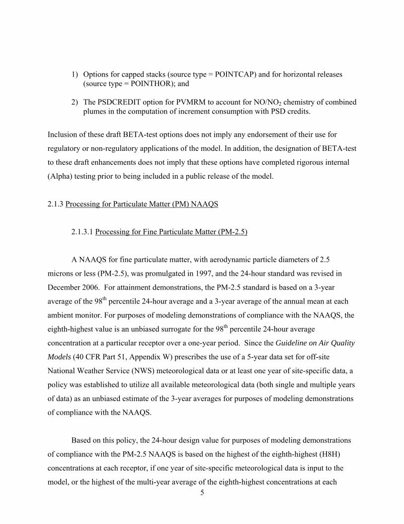
1) Options for capped stacks (source type = POINTCAP) and for horizontal releases (source type = POINTHOR); and
2) The PSDCREDIT option for PVMRM to account for NO/NO2 chemistry of combined
plumes in the computation of increment consumption with PSD credits.
Inclusion of these draft BETA-test options does not imply any endorsement of their use for
regulatory or non-regulatory applications of the model. In addition, the designation of BETA-test
to these draft enhancements does not imply that these options have completed rigorous internal
(Alpha) testing prior to being included in a public release of the model.
2.1.3 Processing for Particulate Matter (PM) NAAQS
2.1.3.1 Processing for Fine Particulate Matter (PM-2.5)
A NAAQS for fine particulate matter, with aerodynamic particle diameters of 2.5
microns or less (PM-2.5), was promulgated in 1997, and the 24-hour standard was revised in
December 2006. For attainment demonstrations, the PM-2.5 standard is based on a 3-year
average of the 98th percentile 24-hour average and a 3-year average of the annual mean at each
ambient monitor. For purposes of modeling demonstrations of compliance with the NAAQS, the
eighth-highest value is an unbiased surrogate for the 98th percentile 24-hour average
concentration at a particular receptor over a one-year period. Since the Guideline on Air Quality
Models (40 CFR Part 51, Appendix W) prescribes the use of a 5-year data set for off-site
National Weather Service (NWS) meteorological data or at least one year of site-specific data, a
policy was established to utilize all available meteorological data (both single and multiple years
of data) as an unbiased estimate of the 3-year averages for purposes of modeling demonstrations
of compliance with the NAAQS.
Based on this policy, the 24-hour design value for purposes of modeling demonstrations
of compliance with the PM-2.5 NAAQS is based on the highest of the eighth-highest (H8H)
concentrations at each receptor, if one year of site-specific meteorological data is input to the
model, or the highest of the multi-year average of the eighth-highest concentrations at each
6
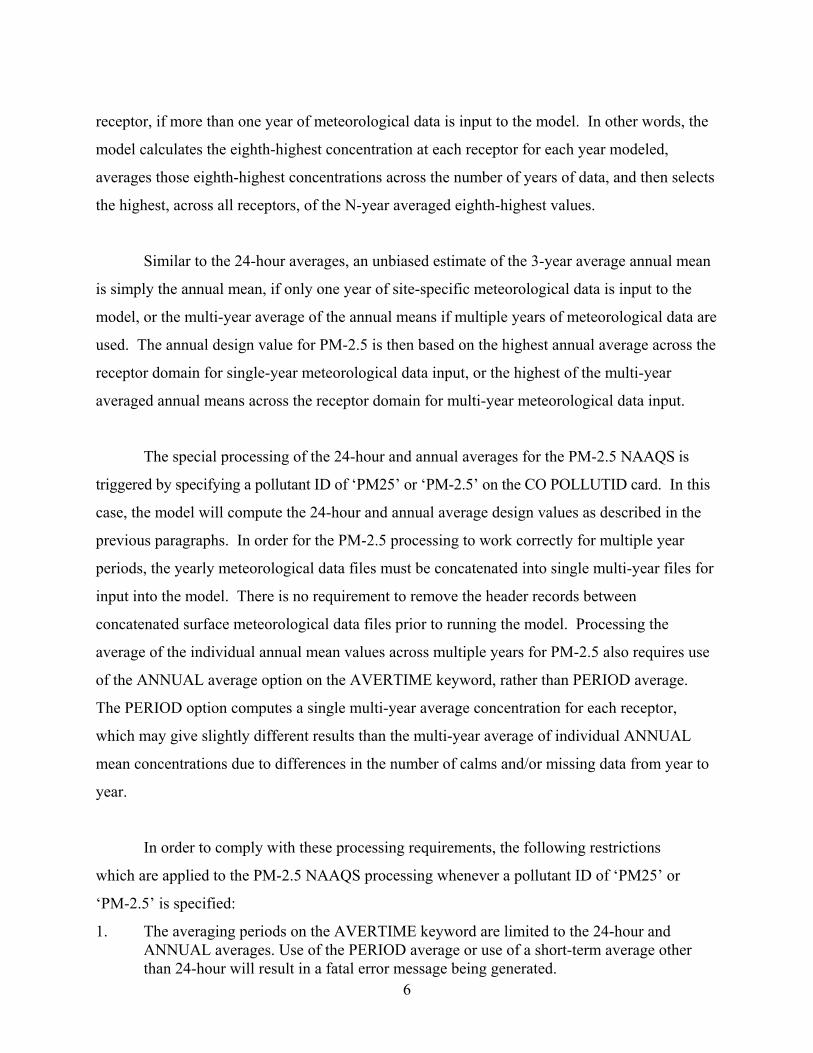
receptor, if more than one year of meteorological data is input to the model. In other words, the
model calculates the eighth-highest concentration at each receptor for each year modeled,
averages those eighth-highest concentrations across the number of years of data, and then selects
the highest, across all receptors, of the N-year averaged eighth-highest values.
Similar to the 24-hour averages, an unbiased estimate of the 3-year average annual mean
is simply the annual mean, if only one year of site-specific meteorological data is input to the
model, or the multi-year average of the annual means if multiple years of meteorological data are
used. The annual design value for PM-2.5 is then based on the highest annual average across the
receptor domain for single-year meteorological data input, or the highest of the multi-year
averaged annual means across the receptor domain for multi-year meteorological data input.
The special processing of the 24-hour and annual averages for the PM-2.5 NAAQS is
triggered by specifying a pollutant ID of ‘PM25’ or ‘PM-2.5’ on the CO POLLUTID card. In this
case, the model will compute the 24-hour and annual average design values as described in the
previous paragraphs. In order for the PM-2.5 processing to work correctly for multiple year
periods, the yearly meteorological data files must be concatenated into single multi-year files for
input into the model. There is no requirement to remove the header records between
concatenated surface meteorological data files prior to running the model. Processing the
average of the individual annual mean values across multiple years for PM-2.5 also requires use
of the ANNUAL average option on the AVERTIME keyword, rather than PERIOD average.
The PERIOD option computes a single multi-year average concentration for each receptor,
which may give slightly different results than the multi-year average of individual ANNUAL
mean concentrations due to differences in the number of calms and/or missing data from year to
year.
In order to comply with these processing requirements, the following restrictions
which are applied to the PM-2.5 NAAQS processing whenever a pollutant ID of ‘PM25’ or
‘PM-2.5’ is specified:
1. The averaging periods on the AVERTIME keyword are limited to the 24-hour and ANNUAL averages. Use of the PERIOD average or use of a short-term average other than 24-hour will result in a fatal error message being generated.
7
2. Only the EIGHTH (or 8TH) highest value may be requested on the RECTABLE keyword for
24-hour averages. Specifying another high value on the RECTABLE card will result in a fatal error message being generated.
3. The model will only process meteorological data for periods of record that span complete
years, although the meteorological data period does not need to follow calendar years (i.e., the data period does not need to start on January 1, hour 1). If the period of record spans less than one complete year of data, a fatal error message will be generated and the model run will be unsuccessful. If additional meteorological data remains after the end of the last complete year of data, the remaining data will be ignored, and a non-fatal warning message will be generated specifying the number of hours ignored.
4. The MULTYEAR card on the CO pathway cannot be used to calculate multi-year
averages for the PM-2.5 NAAQS. Multiple year analyses must be accomplished by including the multiple years of meteorology in a single data file.
5. Since the 24-hour average design values for PM-2.5 analyses may consist of averages
over a multi-year period, they are incompatible with the EVENT processor. If the MAXIFILE option is used to output 24-hour average threshold violations, these may be used with the EVENT processor. Therefore, if the EVENTFIL option is used without the MAXIFILE option for PM-2.5 analyses, a non-fatal warning message will be generated, and the EVENTFIL option will be ignored.
2.1.3.2 Processing for Particulate Matter of 10 Microns or Less (PM-10)
The 24-hour NAAQS for particulate matter with aerodynamic particle diameters of 10
microns or less (PM-10) is in the form of an expected exceedance value, which cannot be
exceeded more than once per year on average over a three year period for purposes of
attainment demonstrations. Modeling demonstrations of compliance with the PM-10 NAAQS
are based on the High-N+1-High value over N years, or in the case of five years of NWS
meteorological data, the High-6th-High (H6H) over five years. In the AERMOD model, the
H6H 24-hour average over five years can be modeled in one of two ways: 1) running five
individual years and combining the results using the CO MULTYEAR option, as described in
Section 3.2.12 of the AERMOD User’s Guide; or 2) using a single five-year meteorological data
file and specifying the SIXTH (or 6TH) highest value on the OU RECTABLE card. If applied
properly, the results of these two approaches will be equivalent. The special processing
consisting of the 99th percentile 24-hour value averaged over N years for PM-10 in previous

8
versions of AERMOD, referred to as the “Post-1997” PM-10 option, has been removed since
that standard was vacated.
2.1.4 Specifying Multiple Urban Areas
The AERMOD model (dated 06341) includes the option to specify multiple urban areas
within the same model run. This option may be applicable for large domains that encompass
more than one identifiable urban area where the separation is large enough to warrant separate
treatment of the urban boundary layer effects. Use of the option for multiple urban areas
eliminates the need for post-processing for such applications. The multiple urban areas are
defined using multiple CO URBANOPT cards. The syntax of the modified URBANOPT
keyword is as follows:
Syntax: For Multiple Urban Areas: CO URBANOPT UrbanID UrbPop (UrbName) (UrbRoughness) For Single Urban Areas: CO URBANOPT UrbPop (UrbName) (UrbRoughness)
Type: Optional, Repeatable for multiple urban areas
where the UrbanID parameter is the alphanumeric urban ID defined by the user (up to eight
characters) when multiple urban areas are defined, the UrbPop parameter specifies the
population of the urban area, the optional UrbName parameter may be used to identify the name
of the urban area, and the optional UrbRoughness parameter may be used to specify the urban
surface roughness length. Note the UrbName must be specified if the user wants to specify the
urban roughness length. A default value of 1.0 meter will be used for the urban roughness length
if the UrbRoughness parameter is omitted. Caution should be used when specifying a non-
default urban roughness length, and use of a non-default value should be clearly documented and
justified. Note that the syntax of the URBANOPT keyword for single urban areas has not
changed from the previous version of AERMOD, so that existing input files will not require
modification.
9
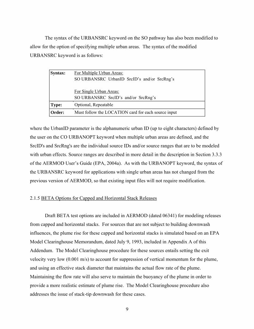
The syntax of the URBANSRC keyword on the SO pathway has also been modified to
allow for the option of specifying multiple urban areas. The syntax of the modified
URBANSRC keyword is as follows:
Syntax: For Multiple Urban Areas: SO URBANSRC UrbanID SrcID’s and/or SrcRng’s For Single Urban Areas: SO URBANSRC SrcID’s and/or SrcRng’s
Type: Optional, Repeatable
Order: Must follow the LOCATION card for each source input
where the UrbanID parameter is the alphanumeric urban ID (up to eight characters) defined by
the user on the CO URBANOPT keyword when multiple urban areas are defined, and the
SrcID's and SrcRng's are the individual source IDs and/or source ranges that are to be modeled
with urban effects. Source ranges are described in more detail in the description in Section 3.3.3
of the AERMOD User’s Guide (EPA, 2004a). As with the URBANOPT keyword, the syntax of
the URBANSRC keyword for applications with single urban areas has not changed from the
previous version of AERMOD, so that existing input files will not require modification.
2.1.5 BETA Options for Capped and Horizontal Stack Releases
Draft BETA test options are included in AERMOD (dated 06341) for modeling releases
from capped and horizontal stacks. For sources that are not subject to building downwash
influences, the plume rise for these capped and horizontal stacks is simulated based on an EPA
Model Clearinghouse Memorandum, dated July 9, 1993, included in Appendix A of this
Addendum. The Model Clearinghouse procedure for these sources entails setting the exit
velocity very low (0.001 m/s) to account for suppression of vertical momentum for the plume,
and using an effective stack diameter that maintains the actual flow rate of the plume.
Maintaining the flow rate will also serve to maintain the buoyancy of the plume in order to
provide a more realistic estimate of plume rise. The Model Clearinghouse procedure also
addresses the issue of stack-tip downwash for these cases.
10
The Model Clearinghouse procedure is not considered appropriate for sources subject to
building downwash influences with the PRIME downwash algorithm for the following reason.
The PRIME algorithm uses the stack diameter to define the initial radius of the plume for the
numerical plume rise calculation; use of an effective diameter adjusted to maintain flow rate is
not appropriate and could produce unrealistic results. For PRIME downwash sources modeled
using the BETA options for capped and horizontal releases, the basic premise of the Model
Clearinghouse procedure, i.e. that the vertical momentum is suppressed while the buoyancy of
the plume is conserved, have been adapted for the PRIME numerical plume rise formulation.
The user selects the BETA options for capped and/or horizontal releases by specifying
one of the new source types on the SO LOCATION card: POINTCAP for capped stacks, and
POINTHOR for horizontal releases. For each of these options, the user specifies the actual stack
parameters [release height (m), exit temperature (K), exit velocity (m/s), and stack diameter (m)]
using the SO SRCPARAM card as if the release were a non-capped vertical point source. The
syntax of the SO LOCATION and SRCPARAM keywords is described in Sections 3.3.1 and
3.3.2, respectively, of the AERMOD User’s Guide (EPA, 2004a). The AERMOD model
performs the necessary adjustments internally to account for plume rise and stack-tip downwash.
For horizontal releases, the model currently assumes that the release is oriented with the wind
direction. For PRIME-downwashed sources, the user-specified exit velocity for horizontal
releases is treated initially as horizontal momentum in the downwind direction.
More details regarding the BETA options for capped and horizontal releases will be
provided later, as warranted based on further testing and evaluation.
2.2 DEPOSITION ALGORITHM INPUTS AND OPTIONS
2.2.1 Definition of Seasons for Gas Dry Deposition
The new deposition algorithms include land use characteristics and some gas deposition
resistance terms based on five seasonal categories, defined in Table 2 of the ANL report as:
11
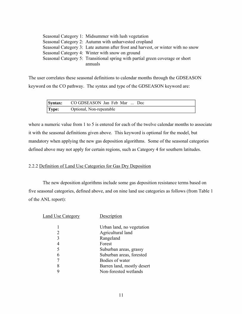
Seasonal Category 1: Midsummer with lush vegetation Seasonal Category 2: Autumn with unharvested cropland Seasonal Category 3: Late autumn after frost and harvest, or winter with no snow Seasonal Category 4: Winter with snow on ground Seasonal Category 5: Transitional spring with partial green coverage or short
annuals
The user correlates these seasonal definitions to calendar months through the GDSEASON
keyword on the CO pathway. The syntax and type of the GDSEASON keyword are:
Syntax: CO GDSEASON Jan Feb Mar ... Dec Type: Optional, Non-repeatable
where a numeric value from 1 to 5 is entered for each of the twelve calendar months to associate
it with the seasonal definitions given above. This keyword is optional for the model, but
mandatory when applying the new gas deposition algorithms. Some of the seasonal categories
defined above may not apply for certain regions, such as Category 4 for southern latitudes.
2.2.2 Definition of Land Use Categories for Gas Dry Deposition
The new deposition algorithms include some gas deposition resistance terms based on
five seasonal categories, defined above, and on nine land use categories as follows (from Table 1
of the ANL report):
Land Use Category Description
1 Urban land, no vegetation 2 Agricultural land 3 Rangeland 4 Forest 5 Suburban areas, grassy 6 Suburban areas, forested 7 Bodies of water 8 Barren land, mostly desert 9 Non-forested wetlands
12
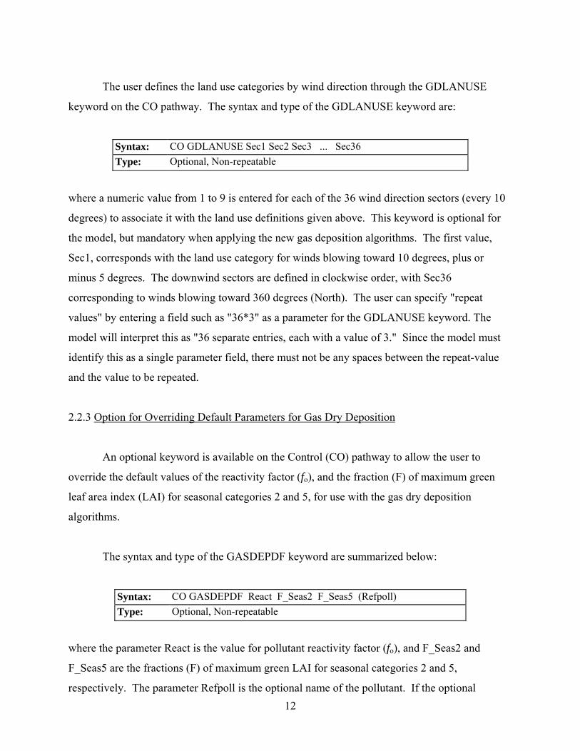
The user defines the land use categories by wind direction through the GDLANUSE
keyword on the CO pathway. The syntax and type of the GDLANUSE keyword are:
Syntax: CO GDLANUSE Sec1 Sec2 Sec3 ... Sec36 Type: Optional, Non-repeatable
where a numeric value from 1 to 9 is entered for each of the 36 wind direction sectors (every 10
degrees) to associate it with the land use definitions given above. This keyword is optional for
the model, but mandatory when applying the new gas deposition algorithms. The first value,
Sec1, corresponds with the land use category for winds blowing toward 10 degrees, plus or
minus 5 degrees. The downwind sectors are defined in clockwise order, with Sec36
corresponding to winds blowing toward 360 degrees (North). The user can specify "repeat
values" by entering a field such as "36*3" as a parameter for the GDLANUSE keyword. The
model will interpret this as "36 separate entries, each with a value of 3." Since the model must
identify this as a single parameter field, there must not be any spaces between the repeat-value
and the value to be repeated.
2.2.3 Option for Overriding Default Parameters for Gas Dry Deposition
An optional keyword is available on the Control (CO) pathway to allow the user to
override the default values of the reactivity factor (fo), and the fraction (F) of maximum green
leaf area index (LAI) for seasonal categories 2 and 5, for use with the gas dry deposition
algorithms.
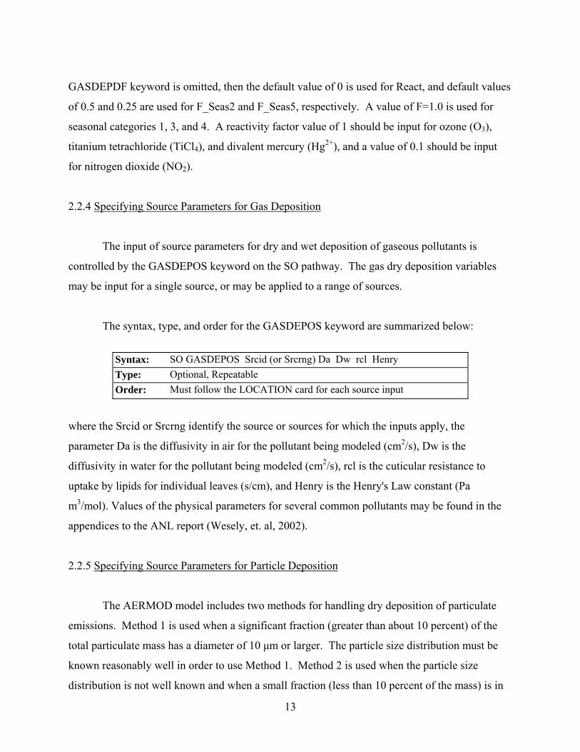
The syntax and type of the GASDEPDF keyword are summarized below:
Syntax: CO GASDEPDF React F_Seas2 F_Seas5 (Refpoll) Type: Optional, Non-repeatable
where the parameter React is the value for pollutant reactivity factor (fo), and F_Seas2 and
F_Seas5 are the fractions (F) of maximum green LAI for seasonal categories 2 and 5,
respectively. The parameter Refpoll is the optional name of the pollutant. If the optional
13
GASDEPDF keyword is omitted, then the default value of 0 is used for React, and default values
of 0.5 and 0.25 are used for F_Seas2 and F_Seas5, respectively. A value of F=1.0 is used for
seasonal categories 1, 3, and 4. A reactivity factor value of 1 should be input for ozone (O3),
titanium tetrachloride (TiCl4), and divalent mercury (Hg2+), and a value of 0.1 should be input
for nitrogen dioxide (NO2).
2.2.4 Specifying Source Parameters for Gas Deposition
The input of source parameters for dry and wet deposition of gaseous pollutants is
controlled by the GASDEPOS keyword on the SO pathway. The gas dry deposition variables
may be input for a single source, or may be applied to a range of sources.
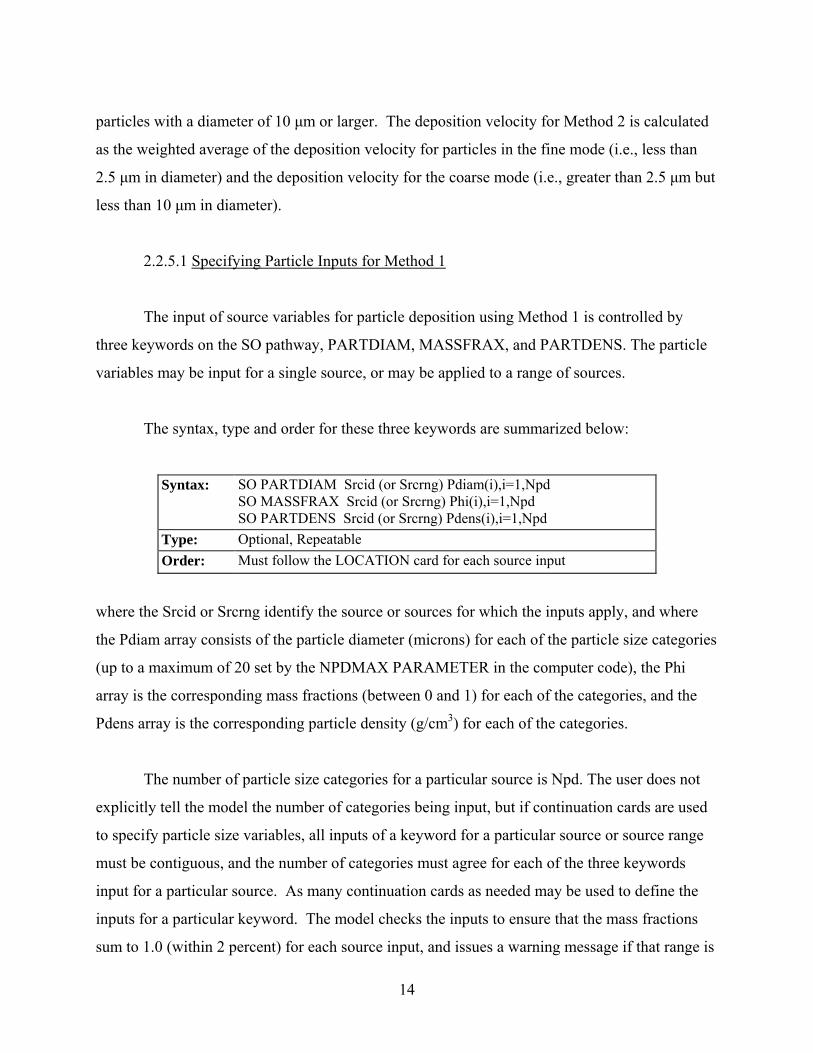
The syntax, type, and order for the GASDEPOS keyword are summarized below:
Syntax: SO GASDEPOS Srcid (or Srcrng) Da Dw rcl Henry Type: Optional, Repeatable Order: Must follow the LOCATION card for each source input
where the Srcid or Srcrng identify the source or sources for which the inputs apply, the
parameter Da is the diffusivity in air for the pollutant being modeled (cm2/s), Dw is the
diffusivity in water for the pollutant being modeled (cm2/s), rcl is the cuticular resistance to
uptake by lipids for individual leaves (s/cm), and Henry is the Henry's Law constant (Pa
m3/mol). Values of the physical parameters for several common pollutants may be found in the
appendices to the ANL report (Wesely, et. al, 2002).
2.2.5 Specifying Source Parameters for Particle Deposition
The AERMOD model includes two methods for handling dry deposition of particulate
emissions. Method 1 is used when a significant fraction (greater than about 10 percent) of the
total particulate mass has a diameter of 10 μm or larger. The particle size distribution must be
known reasonably well in order to use Method 1. Method 2 is used when the particle size
distribution is not well known and when a small fraction (less than 10 percent of the mass) is in
14
particles with a diameter of 10 μm or larger. The deposition velocity for Method 2 is calculated
as the weighted average of the deposition velocity for particles in the fine mode (i.e., less than
2.5 μm in diameter) and the deposition velocity for the coarse mode (i.e., greater than 2.5 μm but
less than 10 μm in diameter).
2.2.5.1 Specifying Particle Inputs for Method 1
The input of source variables for particle deposition using Method 1 is controlled by
three keywords on the SO pathway, PARTDIAM, MASSFRAX, and PARTDENS. The particle
variables may be input for a single source, or may be applied to a range of sources.
The syntax, type and order for these three keywords are summarized below:
Syntax: SO PARTDIAM Srcid (or Srcrng) Pdiam(i),i=1,Npd SO MASSFRAX Srcid (or Srcrng) Phi(i),i=1,Npd SO PARTDENS Srcid (or Srcrng) Pdens(i),i=1,Npd
Type: Optional, Repeatable Order: Must follow the LOCATION card for each source input
where the Srcid or Srcrng identify the source or sources for which the inputs apply, and where
the Pdiam array consists of the particle diameter (microns) for each of the particle size categories
(up to a maximum of 20 set by the NPDMAX PARAMETER in the computer code), the Phi
array is the corresponding mass fractions (between 0 and 1) for each of the categories, and the
Pdens array is the corresponding particle density (g/cm3) for each of the categories.
The number of particle size categories for a particular source is Npd. The user does not
explicitly tell the model the number of categories being input, but if continuation cards are used
to specify particle size variables, all inputs of a keyword for a particular source or source range
must be contiguous, and the number of categories must agree for each of the three keywords
input for a particular source. As many continuation cards as needed may be used to define the
inputs for a particular keyword. The model checks the inputs to ensure that the mass fractions
sum to 1.0 (within 2 percent) for each source input, and issues a warning message if that range is

15
exceeded. The model also ensures that mass fractions for each particle size category are within
the proper range (between 0 and 1), and issues fatal error messages for any value exceeded that
range.
2.2.5.2 Specifying Particle Inputs for Method 2
The Method 2 particle information is input through the METHOD_2 keyword on the SO
pathway. The syntax, type, and order for the METHOD_2 keyword are summarized below:
Syntax: SO METHOD_2 Srcid (or Srcrng) FineMassFraction Dmm Type: Optional, Repeatable Order: Must follow the LOCATION card for each source input
where the Srcid or Srcrng identify the source or sources for which the inputs apply, the
parameter FineMassFraction is the fraction of particle mass emitted in the fine mode, less than
2.5 microns, and Dmm is the representative mass mean particle diameter in microns. Estimated
values of fine particle fractions and mass mean diameters for various pollutants are provided in
Appendix B of the ANL report (Wesely, et al, 2002).
2.2.6 Specifying Emission and Output Units
Since the AERMOD model allows for both concentration and deposition to be output in
the same model run, the EMISUNIT keyword cannot be used to specify emission unit factors if
more than one output type is being generated. The AERMOD model therefore allows for
concentration and deposition units to be specified separately through the CONCUNIT and
DEPOUNIT keywords, respectively. The syntax and type of the CONCUNIT keyword are
summarized below:
Syntax: SO CONCUNIT Emifac Emilbl Conlbl Type: Optional, Non-repeatable
16
where the parameter Emifac is the factor to convert emission rate input units to the desired
output units, Emilbl is the label for the emission input units (up to 40 characters), and Conlbl is
the output unit label (up to 40 characters) for concentration calculations. The syntax and type of
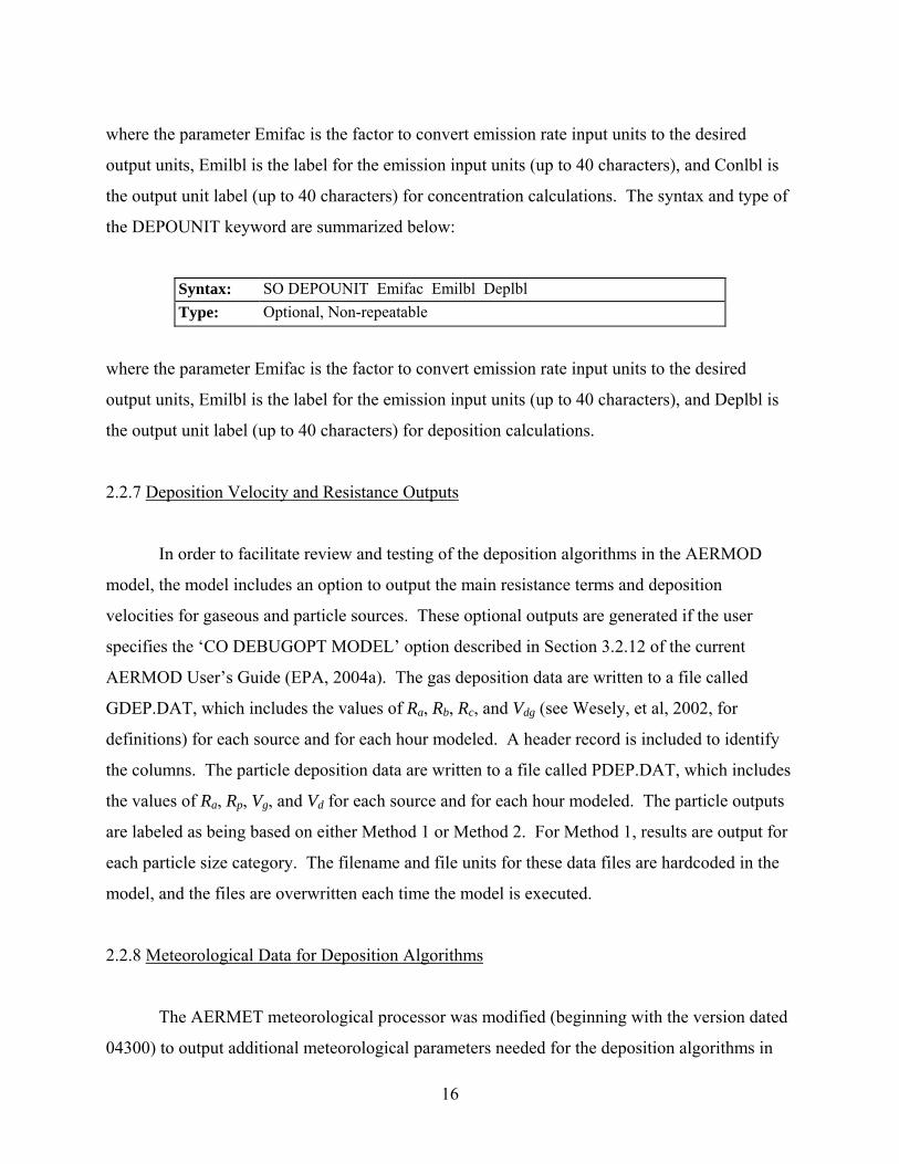
the DEPOUNIT keyword are summarized below:
Syntax: SO DEPOUNIT Emifac Emilbl Deplbl Type: Optional, Non-repeatable
where the parameter Emifac is the factor to convert emission rate input units to the desired
output units, Emilbl is the label for the emission input units (up to 40 characters), and Deplbl is
the output unit label (up to 40 characters) for deposition calculations.
2.2.7 Deposition Velocity and Resistance Outputs
In order to facilitate review and testing of the deposition algorithms in the AERMOD
model, the model includes an option to output the main resistance terms and deposition
velocities for gaseous and particle sources. These optional outputs are generated if the user
specifies the ‘CO DEBUGOPT MODEL’ option described in Section 3.2.12 of the current
AERMOD User’s Guide (EPA, 2004a). The gas deposition data are written to a file called
GDEP.DAT, which includes the values of Ra, Rb, Rc, and Vdg (see Wesely, et al, 2002, for
definitions) for each source and for each hour modeled. A header record is included to identify
the columns. The particle deposition data are written to a file called PDEP.DAT, which includes
the values of Ra, Rp, Vg, and Vd for each source and for each hour modeled. The particle outputs
are labeled as being based on either Method 1 or Method 2. For Method 1, results are output for
each particle size category. The filename and file units for these data files are hardcoded in the
model, and the files are overwritten each time the model is executed.
2.2.8 Meteorological Data for Deposition Algorithms
The AERMET meteorological processor was modified (beginning with the version dated
04300) to output additional meteorological parameters needed for the deposition algorithms in
17
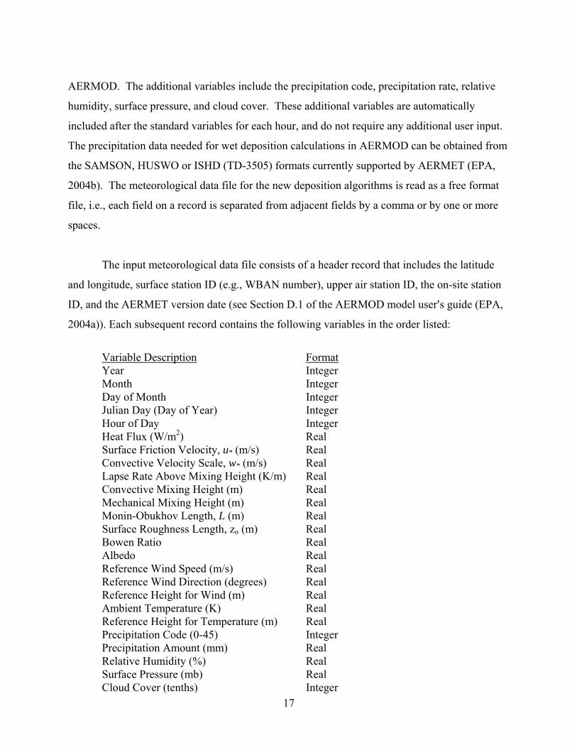
AERMOD. The additional variables include the precipitation code, precipitation rate, relative
humidity, surface pressure, and cloud cover. These additional variables are automatically
included after the standard variables for each hour, and do not require any additional user input.
The precipitation data needed for wet deposition calculations in AERMOD can be obtained from
the SAMSON, HUSWO or ISHD (TD-3505) formats currently supported by AERMET (EPA,
2004b). The meteorological data file for the new deposition algorithms is read as a free format
file, i.e., each field on a record is separated from adjacent fields by a comma or by one or more
spaces.
The input meteorological data file consists of a header record that includes the latitude
and longitude, surface station ID (e.g., WBAN number), upper air station ID, the on-site station
ID, and the AERMET version date (see Section D.1 of the AERMOD model user=s guide (EPA,
2004a)). Each subsequent record contains the following variables in the order listed:
Variable Description Format Year Integer Month Integer Day of Month Integer Julian Day (Day of Year) Integer Hour of Day Integer Heat Flux (W/m2) Real Surface Friction Velocity, u* (m/s) Real Convective Velocity Scale, w* (m/s) Real Lapse Rate Above Mixing Height (K/m) Real Convective Mixing Height (m) Real Mechanical Mixing Height (m) Real Monin-Obukhov Length, L (m) Real Surface Roughness Length, zo (m) Real Bowen Ratio Real Albedo Real Reference Wind Speed (m/s) Real Reference Wind Direction (degrees) Real Reference Height for Wind (m) Real Ambient Temperature (K) Real Reference Height for Temperature (m) Real Precipitation Code (0-45) Integer Precipitation Amount (mm) Real Relative Humidity (%) Real Surface Pressure (mb) Real Cloud Cover (tenths) Integer

18
2.3 OPEN PIT SOURCE OPTION
The open pit source option is invoked by specifying a source type of OPENPIT on the
source location (SO LOCATION) card. The OPENPIT source algorithm can be used to model
particulate emissions from open pits, such as surface coal mines and rock quarries. The
OPENPIT algorithm uses an effective area for modeling pit emissions, based on meteorological
conditions, and then utilizes the numerical integration area source algorithm to model the impact
of emissions from the effective area sources. A complete technical description of the OPENPIT
source algorithm is provided in the ISC3 Model User=s Guide - Volume II (EPA, 1995b).
The AERMOD model accepts rectangular pits with an optional rotation angle specified
relative to a north-south orientation. The rotation angle is specified relative to the vertex used to
define the source location on the SO LOCATION card (e.g., the southwest corner). The syntax,
type and order for the SRCPARAM card for OPENPIT sources are summarized below:
Syntax: SO SRCPARAM Srcid Opemis Relhgt Xinit Yinit Pitvol (Angle) Type: Optional, Repeatable Order: Must follow the LOCATION card for each source input
where the Srcid parameter is the same source ID that was entered on the LOCATION card for a
particular source, and the other parameters are as follows:
Opemis - open pit emission rate in g/(s-m2),
Relhgt - average release height above the base of the pit in meters,
Xinit - length of X side of the open pit (in the east-west direction if Angle is 0 degrees) in meters,
Yinit - length of Y side of the open pit (in the north-south direction if Angle is 0
degrees) in meters, Pitvol - volume of open pit in cubic meters, and
19
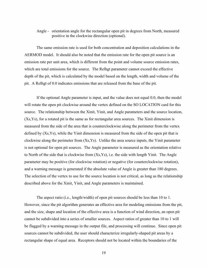
Angle - orientation angle for the rectangular open pit in degrees from North, measured positive in the clockwise direction (optional).
The same emission rate is used for both concentration and deposition calculations in the
AERMOD model. It should also be noted that the emission rate for the open pit source is an
emission rate per unit area, which is different from the point and volume source emission rates,
which are total emissions for the source. The Relhgt parameter cannot exceed the effective
depth of the pit, which is calculated by the model based on the length, width and volume of the
pit. A Relhgt of 0.0 indicates emissions that are released from the base of the pit.
If the optional Angle parameter is input, and the value does not equal 0.0, then the model
will rotate the open pit clockwise around the vertex defined on the SO LOCATION card for this
source. The relationship between the Xinit, Yinit, and Angle parameters and the source location,
(Xs,Ys), for a rotated pit is the same as for rectangular area sources. The Xinit dimension is
measured from the side of the area that is counterclockwise along the perimeter from the vertex
defined by (Xs,Ys), while the Yinit dimension is measured from the side of the open pit that is
clockwise along the perimeter from (Xs,Ys). Unlike the area source inputs, the Yinit parameter
is not optional for open pit sources. The Angle parameter is measured as the orientation relative
to North of the side that is clockwise from (Xs,Ys), i.e. the side with length Yinit. The Angle
parameter may be positive (for clockwise rotation) or negative (for counterclockwise rotation),
and a warning message is generated if the absolute value of Angle is greater than 180 degrees.
The selection of the vertex to use for the source location is not critical, as long as the relationship
described above for the Xinit, Yinit, and Angle parameters is maintained.
The aspect ratio (i.e., length/width) of open pit sources should be less than 10 to 1.
However, since the pit algorithm generates an effective area for modeling emissions from the pit,
and the size, shape and location of the effective area is a function of wind direction, an open pit
cannot be subdivided into a series of smaller sources. Aspect ratios of greater than 10 to 1 will
be flagged by a warning message in the output file, and processing will continue. Since open pit
sources cannot be subdivided, the user should characterize irregularly-shaped pit areas by a
rectangular shape of equal area. Receptors should not be located within the boundaries of the
20
pit; concentration and/or deposition at such receptors will be set to zero. Such receptors will be
identified during model setup and will be flagged in the summary of inputs.
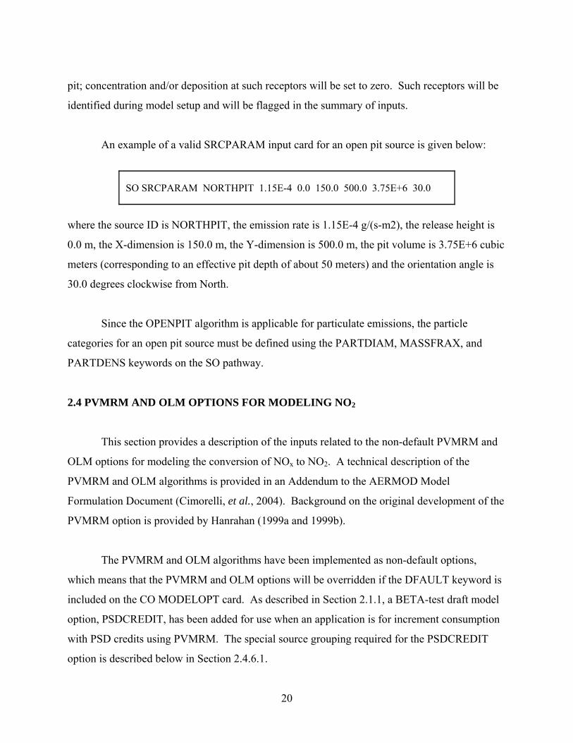
An example of a valid SRCPARAM input card for an open pit source is given below:
SO SRCPARAM NORTHPIT 1.15E-4 0.0 150.0 500.0 3.75E+6 30.0
where the source ID is NORTHPIT, the emission rate is 1.15E-4 g/(s-m2), the release height is
0.0 m, the X-dimension is 150.0 m, the Y-dimension is 500.0 m, the pit volume is 3.75E+6 cubic
meters (corresponding to an effective pit depth of about 50 meters) and the orientation angle is
30.0 degrees clockwise from North.
Since the OPENPIT algorithm is applicable for particulate emissions, the particle
categories for an open pit source must be defined using the PARTDIAM, MASSFRAX, and
PARTDENS keywords on the SO pathway.
2.4 PVMRM AND OLM OPTIONS FOR MODELING NO2
This section provides a description of the inputs related to the non-default PVMRM and
OLM options for modeling the conversion of NOx to NO2. A technical description of the
PVMRM and OLM algorithms is provided in an Addendum to the AERMOD Model
Formulation Document (Cimorelli, et al., 2004). Background on the original development of the
PVMRM option is provided by Hanrahan (1999a and 1999b).
The PVMRM and OLM algorithms have been implemented as non-default options,
which means that the PVMRM and OLM options will be overridden if the DFAULT keyword is
included on the CO MODELOPT card. As described in Section 2.1.1, a BETA-test draft model
option, PSDCREDIT, has been added for use when an application is for increment consumption
with PSD credits using PVMRM. The special source grouping required for the PSDCREDIT
option is described below in Section 2.4.6.1.

21
2.4.1 Specifying Ozone Concentrations for PVMRM and OLM Options
The background ozone concentrations can be input as a single value through the
OZONEVAL keyword on the CO pathway, or may be input as hourly values through a separate
data file specified through the OZONEFIL keyword on the CO pathway. The user must specify
either the OZONEVAL or OZONEFIL keywords, or both, in order to use the PVMRM or OLM
options. If both keywords are entered, then the value entered on the OZONEVAL keyword will
be used to substitute for hours with missing ozone data in the ozone data file.
The syntax of the OZONEVAL keyword is as follows:
Syntax: CO OZONEVAL O3Value (O3Units) Type: Optional, Non-repeatable
where the O3Value parameter is the background ozone concentration in the units specified by
the optional O3Units parameter (PPM, PPB, or UG/M3). If the optional O3Units parameter is
missing, then the model will assume units of micrograms/cubic-meter (UG/M3) for the
background ozone values. If units of PPM or PPB are used, then the model will convert the
concentrations to micrograms/cubic-meter based on the reference ambient temperature and the
base elevation specified on the ME PROFBASE card. The OZONEVAL keyword word is
optional and non-repeatable.
The syntax of the OZONEFIL keyword is as follows:
Syntax: CO OZONEFIL O3FileName (O3Units) (Format) Type: Optional, Non-repeatable
where the O3FileName parameter is the filename for the hourly ozone concentration file, the
optional O3Units parameter specifies the units of the ozone data (PPM, PPB, or UG/M3, with
UG/M3 as the default), and the optional Format parameter specifies the Fortran FORMAT to
read the ozone data. If the optional Format parameter is missing, then the model will read the
ozone data using a Fortran free format, i.e., assuming that commas or spaces separate the data
22
fields. The contents of the ozone data file must include the year (2-digits), month, day, hour and
ozone value in that order (unless specified differently through the Format parameter). The date
sequence in the ozone data file must match the date sequence in the hourly meteorological data
files. As with the OZONEVAL keyword, if units of PPM or PPB are used, then the model will
convert the concentrations to micrograms/cubic-meter based on the reference ambient
temperature and the base elevation specified on the ME PROFBASE card.
Values of ozone concentrations in the ozone data file that are less than zero or greater
than or equal to 900.0 will be regarded as missing. If a background ozone value has been
specified using the OZONEVAL keyword, then that value will be used to substitute for missing
ozone data from the ozone file. If no OZONEVAL keyword is used, then the model will assume
full conversion for hours with missing ozone data.
2.4.2 Specifying the Ambient Equilibrium NO2/NOx Ratio for PVMRM
The PVMRM option for modeling conversion of NO to NO2 incorporates a default
NO2/NOx ambient equilibrium ratio of 0.90. A NO2/NOx equilibrium ratio other than 0.90 can
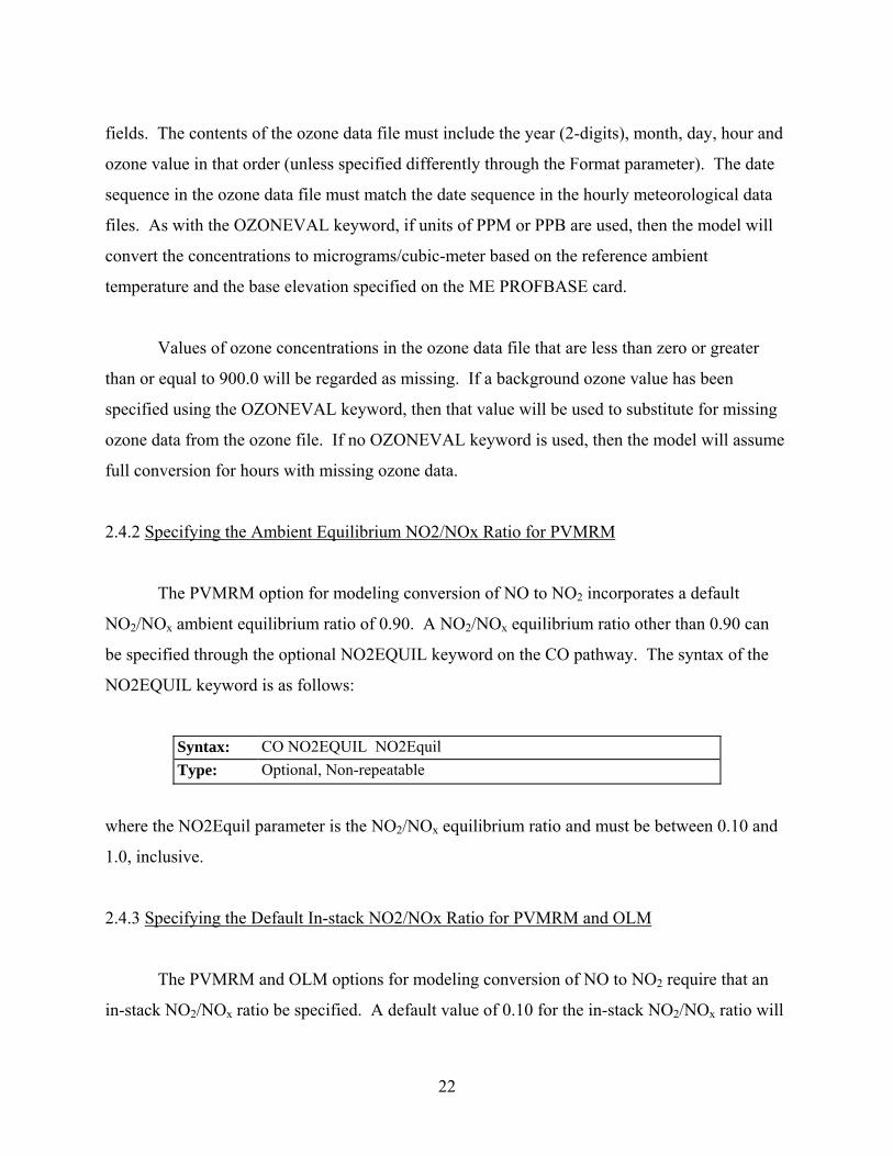
be specified through the optional NO2EQUIL keyword on the CO pathway. The syntax of the
NO2EQUIL keyword is as follows:
Syntax: CO NO2EQUIL NO2Equil Type: Optional, Non-repeatable
where the NO2Equil parameter is the NO2/NOx equilibrium ratio and must be between 0.10 and
1.0, inclusive.
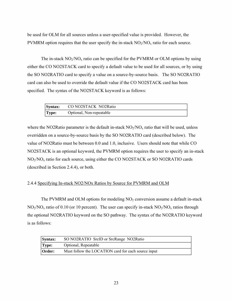
2.4.3 Specifying the Default In-stack NO2/NOx Ratio for PVMRM and OLM
The PVMRM and OLM options for modeling conversion of NO to NO2 require that an
in-stack NO2/NOx ratio be specified. A default value of 0.10 for the in-stack NO2/NOx ratio will
23
be used for OLM for all sources unless a user-specified value is provided. However, the
PVMRM option requires that the user specify the in-stack NO2/NOx ratio for each source.
The in-stack NO2/NOx ratio can be specified for the PVMRM or OLM options by using
either the CO NO2STACK card to specify a default value to be used for all sources, or by using
the SO NO2RATIO card to specify a value on a source-by-source basis. The SO NO2RATIO
card can also be used to override the default value if the CO NO2STACK card has been
specified. The syntax of the NO2STACK keyword is as follows:
Syntax: CO NO2STACK NO2Ratio Type: Optional, Non-repeatable
where the NO2Ratio parameter is the default in-stack NO2/NOx ratio that will be used, unless
overridden on a source-by-source basis by the SO NO2RATIO card (described below). The
value of NO2Ratio must be between 0.0 and 1.0, inclusive. Users should note that while CO
NO2STACK is an optional keyword, the PVMRM option requires the user to specify an in-stack
NO2/NOx ratio for each source, using either the CO NO2STACK or SO NO2RATIO cards
(described in Section 2.4.4), or both.
2.4.4 Specifying In-stack NO2/NOx Ratios by Source for PVMRM and OLM
The PVMRM and OLM options for modeling NO2 conversion assume a default in-stack
NO2/NOx ratio of 0.10 (or 10 percent). The user can specify in-stack NO2/NOx ratios through
the optional NO2RATIO keyword on the SO pathway. The syntax of the NO2RATIO keyword
is as follows:
Syntax: SO NO2RATIO SrcID or SrcRange NO2Ratio Type: Optional, Repeatable Order: Must follow the LOCATION card for each source input
24
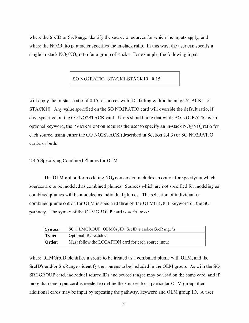
where the SrcID or SrcRange identify the source or sources for which the inputs apply, and
where the NO2Ratio parameter specifies the in-stack ratio. In this way, the user can specify a
single in-stack NO2/NOx ratio for a group of stacks. For example, the following input:
SO NO2RATIO STACK1-STACK10 0.15
will apply the in-stack ratio of 0.15 to sources with IDs falling within the range STACK1 to
STACK10. Any value specified on the SO NO2RATIO card will override the default ratio, if
any, specified on the CO NO2STACK card. Users should note that while SO NO2RATIO is an
optional keyword, the PVMRM option requires the user to specify an in-stack NO2/NOx ratio for
each source, using either the CO NO2STACK (described in Section 2.4.3) or SO NO2RATIO
cards, or both.
2.4.5 Specifying Combined Plumes for OLM
The OLM option for modeling NO2 conversion includes an option for specifying which
sources are to be modeled as combined plumes. Sources which are not specified for modeling as
combined plumes will be modeled as individual plumes. The selection of individual or
combined plume option for OLM is specified through the OLMGROUP keyword on the SO
pathway. The syntax of the OLMGROUP card is as follows:
Syntax: SO OLMGROUP OLMGrpID SrcID’s and/or SrcRange’s Type: Optional, Repeatable Order: Must follow the LOCATION card for each source input
where OLMGrpID identifies a group to be treated as a combined plume with OLM, and the
SrcID's and/or SrcRange's identify the sources to be included in the OLM group. As with the SO
SRCGROUP card, individual source IDs and source ranges may be used on the same card, and if
more than one input card is needed to define the sources for a particular OLM group, then
additional cards may be input by repeating the pathway, keyword and OLM group ID. A user

25
can also specify an OLMGrpID of ALL, which means that OLM will be applied on a combined
plume basis to all sources. However, unlike the SO SRCGROUP card, the results will not be
output for an OLM group unless the same group of sources is also identified on a SRCGROUP
card. Another constraint is that a source cannot be included in more than one OLM group. If a
source is not selected for an OLMGROUP card, then OLM will be applied to that source as an
individual plume. Other than the similarity in syntax, there is no connection in the model
between the groups defined on the OLMGROUP card and groups defined on the SRCGROUP
card. The OLMGROUP card relates to how the results are processed within the model for the
OLM model, and the SRCGROUP card simply controls how source impacts are grouped in the
model outputs.
If the user identifies one or more groups of sources to apply OLM on a combined plume
basis using the OLMGROUP card, the model will still need to calculate the concentration for
individual plumes within the OLM group in order for the model to sum the results for the sources
listed on the SRCGROUP card(s). The individual source concentrations are calculated by
applying the ratio of the combined concentration for the OLM group with and without OLM to
each source within the OLM group.
2.4.6 Modeling NO2 Increment Credits with PVMRM
Due to the ozone-limiting effects of the PVMRM option, the predicted concentrations of
NO2 are not linearly proportional to the emission rate. Therefore, the approach of modeling NO2
increment consumption with PSD credits through the use of a negative emission rate for credit
sources cannot be used with the PVMRM option. However, the draft PSDCREDIT option
allows modeling PSD increment credits for NO2 when the PVMRM option is specified. The
PSDCREDIT option is currently implemented as a BETA-test option, and requires that the
PVMRM and BETA options be specified. The PSDCREDIT option utilizes a new PSDGROUP
keyword, described below, to identify which sources consume or expand increment. This option
is not valid if the OLM option is specified, and no comparable option is available for modeling
increment credits with the OLM option. The user should check with the appropriate reviewing
authority for further guidance on modeling increment credits for NO2.
26
A general discussion of concepts related to modeling increment consumption is provided
below, followed by a description of inputs required to use the BETA-test PSDCREDIT option
for PVMRM.
2.4.6.1 Increment Consuming and Baseline Sources
Increment is the maximum allowable increase in concentration of a pollutant above a
baseline concentration for an area defined under the Prevention of Significant Deterioration
(PSD) regulations. The PSD baseline area can be an entire State or a subregion of a State such as
a county or group of counties. Increment standards exist for three pollutants: SO2 (3-hr, 24-hr,
and annual averages), NO2 (annual average), and PM-10 (24-hr and annual average). Increment
consumption is the additional air quality impact above a baseline concentration.
The baseline concentration is the ambient concentration of the pollutant that existed in
the area at the time of the submittal of the first complete permit application by any source in that
area subject to PSD regulations. A baseline source is any source that existed prior to that first
application and the baseline date is the date of the PSD application. This baseline date is referred
to as the minor source baseline date in PSD regulations. By definition, baseline sources do not
consume increment. However, any baseline source that retires from service after the baseline
date expands the increment available to new sources. Therefore, a PSD modeling analysis
performed for a new source may need to account for this increment expansion. Such an analysis
may therefore involve identification of three groups of sources: 1) increment-consuming sources;
2) retired (increment-expanding) baseline sources; and 3) existing, non-retired, baseline sources.
2.4.6.2 Calculating Increment Consumption under the PSDCREDIT Option
Calculating increment consumption under the PSDCREDIT option in AERMOD is not a
simple arithmetic exercise involving the three groups of sources defined above. Since the
amount of ozone available in the atmosphere limits the conversion of NO to NO2, interactions of
plumes from the existing and retired baseline sources with those from the increment consuming
27
sources must be considered as part of the calculation of net increment consumption. Without the
PSDCREDIT option, properly accounting for the potential interaction of plumes among the
different source categories would require post-processing of results from multiple model runs.
Internal “post”-processing algorithms have been incorporated in AERMOD under the
PSDCREDIT option to account for the apportioning of the three groups of sources to properly
calculate increment consumption from a single model run.
Define the following three source groupings for the discussion that follows:
A = increment-consuming sources;
B = non-retired baseline sources; and
C = retired baseline, increment-expanding sources.
The calculation of the amount of increment consumption by the A sources cannot simply be
estimated by modeling the A sources alone because of the possible interaction of those plumes
with the plumes from B sources. The PVMRM algorithm is designed to account for such plume
interactions and calculate the total NO to NO2 conversion in the combined plumes based on the
amount of ozone available. Therefore, the total increment consumption by the A sources is
given by the difference between (1) the total future impact of increment consuming sources and
non-retired baseline sources (A+B) and (2) the total current impact (B), which can be expressed
as (A+B) – (B). Here (A+B) represents the value that would be compared against the National
Ambient Air Quality Standard (NAAQS) for NO2 during PSD review of the A sources.
In a case where some of the baseline sources have been retired from service (C sources),
the PSD regulations allow the consideration of increment expansion when assessing compliance
with the PSD increment. However, the amount of increment expansion cannot be estimated by
simply modeling the C sources alone because of the possible interaction of those plumes with the
plumes from B sources. Therefore, the total increment expansion, i.e., PSD credit, is calculated
as the difference between (1) the total impact prior to the retirement of C sources, i.e. (B+C),
and (2) the total impact from existing (non-retired) baseline sources (B), which can be expressed
as (B+C) – (B).
28
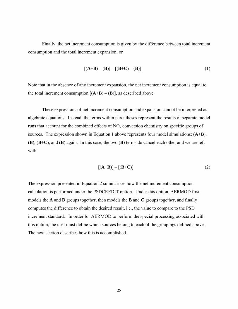
Finally, the net increment consumption is given by the difference between total increment
consumption and the total increment expansion, or
[(A+B) – (B)] – [(B+C) – (B)] (1)
Note that in the absence of any increment expansion, the net increment consumption is equal to
the total increment consumption [(A+B) – (B)], as described above.
These expressions of net increment consumption and expansion cannot be interpreted as
algebraic equations. Instead, the terms within parentheses represent the results of separate model
runs that account for the combined effects of NOx conversion chemistry on specific groups of
sources. The expression shown in Equation 1 above represents four model simulations: (A+B),
(B), (B+C), and (B) again. In this case, the two (B) terms do cancel each other and we are left
with
[(A+B)] – [(B+C)] (2)
The expression presented in Equation 2 summarizes how the net increment consumption
calculation is performed under the PSDCREDIT option. Under this option, AERMOD first
models the A and B groups together, then models the B and C groups together, and finally
computes the difference to obtain the desired result, i.e., the value to compare to the PSD
increment standard. In order for AERMOD to perform the special processing associated with
this option, the user must define which sources belong to each of the groupings defined above.
The next section describes how this is accomplished.
29
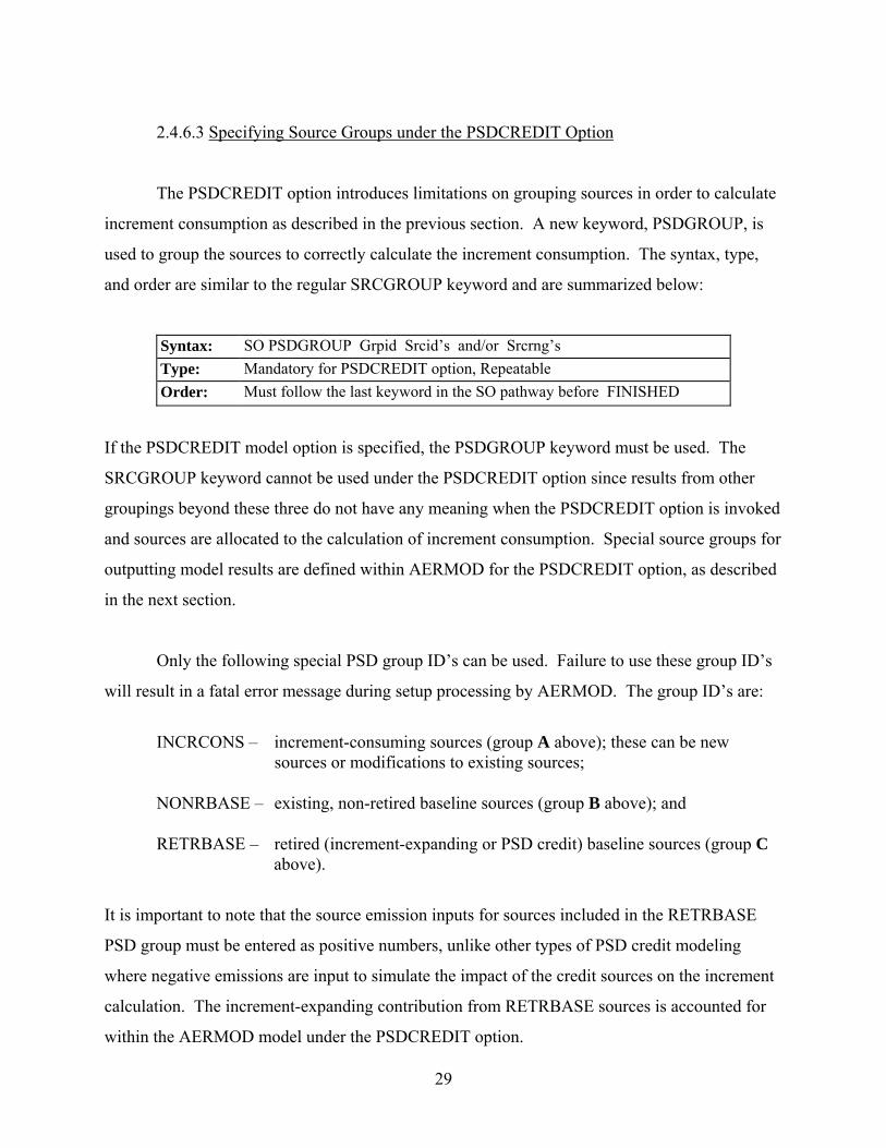
2.4.6.3 Specifying Source Groups under the PSDCREDIT Option
The PSDCREDIT option introduces limitations on grouping sources in order to calculate
increment consumption as described in the previous section. A new keyword, PSDGROUP, is
used to group the sources to correctly calculate the increment consumption. The syntax, type,
and order are similar to the regular SRCGROUP keyword and are summarized below:
Syntax: SO PSDGROUP Grpid Srcid’s and/or Srcrng’s Type: Mandatory for PSDCREDIT option, Repeatable Order: Must follow the last keyword in the SO pathway before FINISHED
If the PSDCREDIT model option is specified, the PSDGROUP keyword must be used. The
SRCGROUP keyword cannot be used under the PSDCREDIT option since results from other
groupings beyond these three do not have any meaning when the PSDCREDIT option is invoked
and sources are allocated to the calculation of increment consumption. Special source groups for
outputting model results are defined within AERMOD for the PSDCREDIT option, as described
in the next section.
Only the following special PSD group ID’s can be used. Failure to use these group ID’s
will result in a fatal error message during setup processing by AERMOD. The group ID’s are:
INCRCONS – increment-consuming sources (group A above); these can be new
sources or modifications to existing sources; NONRBASE – existing, non-retired baseline sources (group B above); and RETRBASE – retired (increment-expanding or PSD credit) baseline sources (group C
above).
It is important to note that the source emission inputs for sources included in the RETRBASE
PSD group must be entered as positive numbers, unlike other types of PSD credit modeling
where negative emissions are input to simulate the impact of the credit sources on the increment
calculation. The increment-expanding contribution from RETRBASE sources is accounted for
within the AERMOD model under the PSDCREDIT option.
30
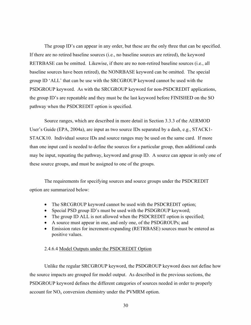
The group ID’s can appear in any order, but these are the only three that can be specified.
If there are no retired baseline sources (i.e., no baseline sources are retired), the keyword
RETRBASE can be omitted. Likewise, if there are no non-retired baseline sources (i.e., all
baseline sources have been retired), the NONRBASE keyword can be omitted. The special
group ID ‘ALL’ that can be use with the SRCGROUP keyword cannot be used with the
PSDGROUP keyword. As with the SRCGROUP keyword for non-PSDCREDIT applications,
the group ID’s are repeatable and they must be the last keyword before FINISHED on the SO
pathway when the PSDCREDIT option is specified.
Source ranges, which are described in more detail in Section 3.3.3 of the AERMOD
User’s Guide (EPA, 2004a), are input as two source IDs separated by a dash, e.g., STACK1-
STACK10. Individual source IDs and source ranges may be used on the same card. If more
than one input card is needed to define the sources for a particular group, then additional cards
may be input, repeating the pathway, keyword and group ID. A source can appear in only one of
these source groups, and must be assigned to one of the groups.
The requirements for specifying sources and source groups under the PSDCREDIT
option are summarized below:
• The SRCGROUP keyword cannot be used with the PSDCREDIT option; • Special PSD group ID’s must be used with the PSDGROUP keyword; • The group ID ALL is not allowed when the PSDCREDIT option is specified; • A source must appear in one, and only one, of the PSDGROUPs; and • Emission rates for increment-expanding (RETRBASE) sources must be entered as
positive values.
2.4.6.4 Model Outputs under the PSDCREDIT Option
Unlike the regular SRCGROUP keyword, the PSDGROUP keyword does not define how
the source impacts are grouped for model output. As described in the previous sections, the
PSDGROUP keyword defines the different categories of sources needed in order to properly
account for NOx conversion chemistry under the PVMRM option.
31
The model outputs under the PSDCREDIT option in AERMOD are based on
demonstrating compliance with the air quality standards, i.e., the NAAQS and PSD increment
for NO2. As a result, AERMOD uses hardcoded “SRCGROUP” names of ‘NAAQS’ and
‘PSDINC’ to label these two types of outputs. The results output under the ‘NAAQS’ source
group label are based on the calculation of (A+B) as described above in Section 2.4.6.2. The
results reported under the ‘PSDINC’ source group label are based on the expression presented
above in Equation 2.
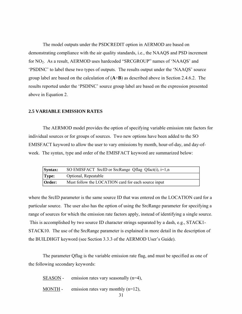
2.5 VARIABLE EMISSION RATES
The AERMOD model provides the option of specifying variable emission rate factors for
individual sources or for groups of sources. Two new options have been added to the SO
EMISFACT keyword to allow the user to vary emissions by month, hour-of-day, and day-of-
week. The syntax, type and order of the EMISFACT keyword are summarized below:
Syntax: SO EMISFACT SrcID or SrcRange Qflag Qfact(i), i=1,n Type: Optional, Repeatable Order: Must follow the LOCATION card for each source input
where the SrcID parameter is the same source ID that was entered on the LOCATION card for a
particular source. The user also has the option of using the SrcRange parameter for specifying a
range of sources for which the emission rate factors apply, instead of identifying a single source.
This is accomplished by two source ID character strings separated by a dash, e.g., STACK1-
STACK10. The use of the SrcRange parameter is explained in more detail in the description of
the BUILDHGT keyword (see Section 3.3.3 of the AERMOD User’s Guide).
The parameter Qflag is the variable emission rate flag, and must be specified as one of
the following secondary keywords:
SEASON - emission rates vary seasonally (n=4), MONTH - emission rates vary monthly (n=12),
32
HROFDY - emission rates vary by hour-of-day (n=24), WSPEED - emission rates vary by wind speed (n=6), SEASHR - emission rates vary by season and hour-of-day (n=96), SHRDOW - emission rates vary by season, hour-of-day, and day-of-week [M-F, Sat,
Sun] (n=288), SHRDOW7 - emission rates vary by season, hour-of-day, and the seven days of the
week [M, Tu, W, Th, F, Sat, Sun] (n=672), MHRDOW - emission rates vary by month, hour-of-day, and day-of-week [M-F, Sat,
Sun] (n=864), and MHRDOW7 - emission rates vary by month, hour-of-day, and the seven days of the
week [M, Tu, W, Th, F, Sat, Sun] (n=2,016).
The Qfact array is the array of factors, where the number of factors is shown above for
each Qflag option. The seasons are defined in the following order: Winter (Dec., Jan., Feb.),
Spring (Mar., Apr., May), Summer (Jun., Jul., Aug.), and Fall (Sep., Oct., Nov.). The wind speed
categories used with the WSPEED option may be defined using the ME WINDCATS keyword.
If the WINDCATS keyword is not used, the default wind speed categories are defined by the
upper bound of the first five categories as follows (the sixth category is assumed to have no
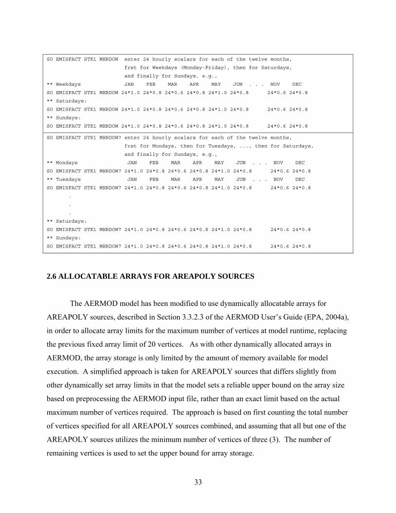
upper bound): 1.54, 3.09, 5.14, 8.23, and 10.8 m/s. The EMISFACT card may be repeated as
many times as necessary to input all of the factors, and repeat values may be used for the
numerical inputs. Examples for the new MHRDOW options are presented below, with column
headers to indicate the order in which values are to be to input:
33
SO EMISFACT STK1 MHRDOW enter 24 hourly scalars for each of the twelve months,
frst for Weekdays (Monday-Friday), then for Saturdays,
and finally for Sundays, e.g.,
** Weekdays JAN FEB MAR APR MAY JUN . . . NOV DEC
SO EMISFACT STK1 MHRDOW 24*1.0 24*0.8 24*0.6 24*0.8 24*1.0 24*0.8 24*0.6 24*0.8
** Saturdays:
SO EMISFACT STK1 MHRDOW 24*1.0 24*0.8 24*0.6 24*0.8 24*1.0 24*0.8 24*0.6 24*0.8
** Sundays:
SO EMISFACT STK1 MHRDOW 24*1.0 24*0.8 24*0.6 24*0.8 24*1.0 24*0.8 24*0.6 24*0.8
SO EMISFACT STK1 MHRDOW7 enter 24 hourly scalars for each of the twelve months,
frst for Mondays, then for Tuesdays, ..., then for Saturdays,
and finally for Sundays, e.g.,
** Mondays JAN FEB MAR APR MAY JUN . . . NOV DEC
SO EMISFACT STK1 MHRDOW7 24*1.0 24*0.8 24*0.6 24*0.8 24*1.0 24*0.8 24*0.6 24*0.8
** Tuesdays JAN FEB MAR APR MAY JUN . . . NOV DEC
SO EMISFACT STK1 MHRDOW7 24*1.0 24*0.8 24*0.6 24*0.8 24*1.0 24*0.8 24*0.6 24*0.8
.
.
.
** Saturdays:
SO EMISFACT STK1 MHRDOW7 24*1.0 24*0.8 24*0.6 24*0.8 24*1.0 24*0.8 24*0.6 24*0.8
** Sundays:
SO EMISFACT STK1 MHRDOW7 24*1.0 24*0.8 24*0.6 24*0.8 24*1.0 24*0.8 24*0.6 24*0.8
2.6 ALLOCATABLE ARRAYS FOR AREAPOLY SOURCES
The AERMOD model has been modified to use dynamically allocatable arrays for
AREAPOLY sources, described in Section 3.3.2.3 of the AERMOD User’s Guide (EPA, 2004a),
in order to allocate array limits for the maximum number of vertices at model runtime, replacing
the previous fixed array limit of 20 vertices. As with other dynamically allocated arrays in
AERMOD, the array storage is only limited by the amount of memory available for model
execution. A simplified approach is taken for AREAPOLY sources that differs slightly from
other dynamically set array limits in that the model sets a reliable upper bound on the array size
based on preprocessing the AERMOD input file, rather than an exact limit based on the actual
maximum number of vertices required. The approach is based on first counting the total number
of vertices specified for all AREAPOLY sources combined, and assuming that all but one of the
AREAPOLY sources utilizes the minimum number of vertices of three (3). The number of
remaining vertices is used to set the upper bound for array storage.
34
Since the AREACIRC option for circular area sources, described in Section 3.3.2.3 of the
AERMOD User’s Guide (EPA, 2004a), uses the same data arrays as the AREAPOLY source, the
array limit determined for AREAPOLY sources will also apply for AREACIRC sources if both
source types are used in the same model run. However, the maximum number of vertices
allowed for AREACIRC sources will always be at least 50, regardless of whether AREAPOLY
sources are included in the same model run.
35
3.0 REFERENCES
Cimorelli, A. J., S. G. Perry, A. Venkatram, J. C. Weil, R. J. Paine, R. B. Wilson, R. F. Lee, W. D. Peters, R. W. Brode, and J. O. Paumier, 2004: AERMOD: Description of Model Formulation. EPA 454/R-03-004. U. S. Environmental Protection Agency, Research Triangle Park, North Carolina 27711. Environmental Protection Agency, 1995a: User=s Guide for the Industrial Source Complex (ISC3) Dispersion Models, Volume I - User Instructions. EPA-454/B-95-003a. U.S. Environmental Protection Agency, Research Triangle Park, North Carolina 27711. Environmental Protection Agency, 1995b: User=s Guide for the Industrial Source Complex (ISC3) Dispersion Models, Volume II - Description of Model Algorithms. EPA-454/B-95-003b. U.S. Environmental Protection Agency, Research Triangle Park, North Carolina 27711. Environmental Protection Agency, 2003: AERMOD Deposition Algorithms - Science Document (Revised Draft). U.S. Environmental Protection Agency, Research Triangle Park, North Carolina 27711. Environmental Protection Agency, 2004a: User=s Guide for the AMS/EPA Regulatory Model - AERMOD. EPA-454/B-03-001. U.S. Environmental Protection Agency, Research Triangle Park, North Carolina 27711. Environmental Protection Agency, 2004b: User=s Guide for the AERMOD Meteorological Processor (AERMET). EPA-454/B-03-002. U.S. Environmental Protection Agency, Research Triangle Park, North Carolina 27711. Hanrahan, P.L., 1999a. "The plume volume molar ratio method for determining NO2/NOx ratios in modeling. Part I: Methodology," J. Air & Waste Manage. Assoc., 49, 1324-1331. Hanrahan, P.L., 1999b. "The plume volume molar ratio method for determining NO2/NOx ratios in modeling. Part II: Evaluation Studies," J. Air & Waste Manage. Assoc., 49, 1332-1338.
Walcek, C., G. Stensland, L. Zhang, H. Huang, J. Hales, C. Sweet, W. Massman, A. Williams, J, Dicke, 2001: Scientific Peer-Review of the Report "Deposition Parameterization for the Industrial Source Complex (ISC3) Model." The KEVRIC Company, Durham, North Carolina. Wesely, M.L, P.V. Doskey, and J.D. Shannon, 2002: Deposition Parameterizations for the Industrial Source Complex (ISC3) Model. Draft ANL report ANL/ER/TRB01/003, DOE/xx-nnnn, Argonne National Laboratory, Argonne, Illinois 60439. Note: All references listed here, with the exception of Hanrahan (1999a and 1999b), can be found on the U.S. EPA SCRAM website at the following url: http://www.epa.gov/scram001/
36
APPENDIX A
EPA Model Clearinghouse Memorandum Dated July 9, 1993
37
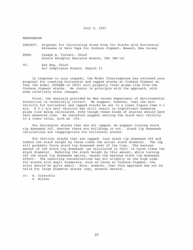
July 9, 1993 MEMORANDUM SUBJECT: Proposal for Calculating Plume Rise for Stacks with Horizontal Releases or Rain Caps for Cookson Pigment, Newark, New Jersey FROM: Joseph A. Tikvart, Chief Source Receptor Analysis Branch, TSD (MD-14) TO: Ken Eng, Chief Air Compliance Branch, Region II In response to your request, the Model Clearinghouse has reviewed your proposal for treating horizontal and capped stacks at Cookson Pigment so that the model (SCREEN or ISC2) will properly treat plume rise from the Cookson Pigment stacks. We concur in principle with the approach, with some relatively minor changes. First, the analysis provided by New Jersey Department of Environmental Protection is technically correct. We suggest, however, that the exit velocity for horizontal and capped stacks be set to a lower figure than 0.1 m/s. A 0.1 m/s exit velocity may still result in significant momentum plume rise being calculated, even though these kinds of sources should have zero momentum rise. We therefore suggest setting the stack exit velocity to a lower value, such as .001. For horizontal stacks that are not capped, we suggest turning stack tip downwash off, whether there are buildings or not. Stack tip downwash calculations are inappropriate for horizontal stacks. For vertical stacks that are capped, turn stack tip downwash off and reduce the stack height by three times the actual stack diameter. The cap will probably force stack tip downwash most of the time. The maximum amount of the stack tip downwash (as calculated in ISC2) is three times the stack diameter. Reducing the stack height by this amount, while turning off the stack tip downwash option, causes the maximum stack tip downwash effect. The resulting concentrations may err slightly on the high side. For stacks with small diameters, such as those at Cookson Pigment, the error should be quite small. Note, however, that this approach may not be valid for large diameter stacks (say, several meters). cc: A. Colecchia D. Wilson