Embed Size (px)
Citation preview

AERC 1
Procedures for Determining Energy Performance Properties of Fenestration Attachments
Published by Attachments Energy Rating Council
355 Lexington Avenue, New York, New York, 10017
Copyright © 2017 by the Attachments Energy Rating Council Not to be reproduced without
specific authorization from AERC
Printed in the USA
This Standard was developed by the Attachments Energy Rating Council

AERC 1 Version 1.2
1
Foreword
The Attachments Energy Rating Council (AERC) is an independent, public interest, non-profit organization whose mission is to develop and maintain a program to allow participants to rate, label, and certify the performance of fenestration attachments.
This document, AERC 1, provides the main technical rating procedures to determine the energy performance properties (U-factor, SHGC, VT, and Air Leakage) of fenestration attachments installed in combination with standardized baseline windows and skylights under standardized conditions. AERC 2 provides the procedures to determine the corresponding annual energy performance ratings for fenestration attachments when used in a model residential home: Energy Performance Index for heating, EPH, and Energy Performance Index for cooling, EPC. AERC 1 and AERC 2 are supported by AERC 1.1 which provides the technical procedures for determining material property inputs (optical and thermophysical properties), and AERC 1.2 which provides physical testing procedures. The energy performance ratings determined by these technical procedures are designed to be used in conjunction with AERC’s labeling and certification program, as detailed in AERC 100 National Standard for Rating the Energy Performance of Fenestration Attachments.
The attachment product types currently covered by this standard are listed in Section 2. Other product types such as awnings, window quilts, roller shutters, louvered shutters, roman shades, drapes, and sheer shades may be added in future versions of the standard as technical procedures are developed.
1. Introduction
The purpose of this standard is to provide the technical rating procedures to determine the energy performance properties of fenestration attachments installed in combination with standardized baseline windows and skylights under standardized conditions. The energy performance properties include overall heat transfer coefficient (U-factor), solar heat gain coefficient (SHGC), visible transmittance (VT), and air leakage (AL). AERC 2 provides the procedures to determine the corresponding annual energy performance ratings for fenestration attachments when used in a model residential home: Energy Performance Index for heating, EPH, and Energy Performance Index for cooling, EPC.
2. Scope
This standard shall apply to interior and exterior fenestration attachments, defined as products attached to fenestration, or attached to or near the perimeter of the inner or outer wall surrounding fenestration.
The technical procedures of this standard apply to the following fenestration attachment product types:
Cellular Shades
Slat Shades
Roller Shades

AERC 1 Version 1.2
2
Storm Windows and Window Panels
Pleated Shades
Solar Screens
Surface Applied Films
This standard does not apply to or address:
Primary fenestration inclusive of windows, doors, and skylights.
Fenestration attachments over windows or doors in interior walls of buildings and not part of the thermal envelope of the building.
Changes in performance properties over time of fenestration attachments or the windows, doors, and skylights over which they are installed.
Changes in performance properties using conditions other than the standardized environmental, installation, and baseline window conditions specified in this document.
3. Referenced Documents and Standards
AERC 1.1-2017 – Procedures for Determining the Optical and Thermal Properties of Window Attachment Materials, Attachments Energy Rating Council, New York NY, 2017, www.aercnet.org.
AERC 1.2-2017, Physical Test Methods for Measuring Energy Performance Properties of Fenestration Attachments, Attachments Energy Rating Council, New York NY, 2017, www.aercnet.org.
AERC 2-2017, Procedures for Determining Heating and Cooling Annual Energy Performance Ratings of Fenestration Attachments, Attachments Energy Rating Council, New York NY, 2017, www.aercnet.org.
AERC 400, Policies and Procedures, Attachments Energy Rating Council, New York NY, 2017, www.aercnet.org.
AERC 1.3-2017, AERC Simulation Manual, Lawrence Berkeley National Laboratory, Berkeley CA, 2017.
Complex Glazing Database (CGDB), Lawrence Berkeley National Laboratory, Berkeley CA, 2017. https://windows.lbl.gov/software/
Certified Product Database (CPD), Attachments Energy Rating Council, New York NY, 2017, www.aercnet.org.
IEEE/ASTM SI 10-2010, American National Standard for Metric Practice, ASTM International, West Conshohocken PA, 2010, www.astm.org.
International Glazing Database (IGDB), Lawrence Berkeley National Laboratory, Berkeley CA, 2015. https://windows.lbl.gov/software/
ISO 15099:2003, Thermal Performance of Windows, Doors and Shading Devices — Detailed Calculations, International Organization for Standardization, 2003.

AERC 1 Version 1.2
3
THERM 7, Lawrence Berkeley National Laboratory, Berkeley CA, 2017. https://windows.lbl.gov/software/
WINDOW 7, Lawrence Berkeley National Laboratory, Berkeley CA, 2017. https://windows.lbl.gov/software/
4. Terminology
4.1. Definitions
See AERC 400 Appendix A. Where there is a difference in definition between AERC 400 Appendix A and other reference documents, the definition from AERC 400 shall take precedence.
4.2. Acronyms
AERC Attachments Energy Rating Council
AL Air leakage
ASHRAE American Society of Heating, Refrigerating, and Air-Conditioning Engineers
ASTM American Society of Testing Materials
CPD Certified product database
CGDB Complex glazing database
EPH Energy Performance Index for heating
EPC Energy Performance Index for cooling
IGDB International glazing database
ISO International Standards Organization
NFRC National Fenestration Rating Council
SHGC Solar heat gain coefficient
VT Visible transmittance
5. Technical Procedures
This section provides the procedures for determining U-factor, SHGC, VT, and AL ratings of fenestration attachment products used in combination with standardized baseline windows and skylights under standardized conditions.
Section 5.1 includes the general requirements that apply to all fenestration attachment products.
Section 5.2 includes variations and additions to these requirements that pertain to specific product types, including definitions of characteristics that distinguish individual products within each product type.

AERC 1 Version 1.2
4
To standardize performance comparisons between products, determination of the U-factor, SHGC, and VT using one specific baseline window (Baseline Window B in Section 5.1.1.1) is required for attachment products for use in labeling and listing in the AERC CPD. Additionally, the U-factor, SHGC, and VT of attachment products may optionally be determined using other standardized baseline windows, skylights, and doors as outlined in Section 5.1.1.1.
Test procedures are also provided for determining AL ratings of fenestration attachment products. AL ratings are only required for some attachment product types, as specified in Sections 5.1.5 and 5.2.
5.1. Procedures Applicable to All Attachment Products
5.1.1. Standardized Conditions
5.1.1.1. Baseline Windows and Skylights
Appendix A provides specifications (dimensions, materials, and standard sizes) for the following Baseline Windows that may be used for determining U-factor, SHGC, and VT ratings of fenestration attachments. AL ratings of fenestration attachments are not determined over a baseline window, but are instead tested over a calibration test panel as described in Section 5.1.5.
Baseline Windows: A. Nonmetal-framed, single pane, clear (optional) B. Nonmetal-framed, double pane, clear (required for U, SHGC, VT) C. Nonmetal-framed, double pane, low-E (optional) D. Metal-framed, single pane, clear (optional) E. Metal-framed, double pane, clear (optional) F. Metal-framed, double pane, low-E (optional)
At a minimum, the U-factor, SHGC, and VT of all fenestration attachments shall be determined in accordance with Sections 5.1.2, 5.1.3, and 5.1.4 in combination with Baseline Window B (nonmetal-framed, double pane, clear glass).
In addition, the U-factor, SHGC, and VT of fenestration attachments may optionally be determined in accordance with Sections 5.1.2, 5.1.3, and 5.1.4 in combination with any of the Baseline Windows listed above and specified in Appendix A, so long as the performance properties are also determined for baseline window B.
Ratings for attachment products intended for use over vertical fenestration shall be determined with the baseline window in the vertical orientation.
Ratings for attachment products intended for use over skylights and other sloped fenestration shall be determined with the baseline window rotated at a slope of 20 degrees above horizontal.
Non-rectangular products shall be rated as rectangular products over these baseline windows using the same materials and at the size specified in Appendix A.
AERC 1 Version 1.2
5
5.1.1.2. Attachment Installation
Ratings for attachment products shall be determined with the product installed over the baseline windows / skylights of Section 5.1.1.1 following the manufacturer’s installation instructions and as specified in this section and Appendix A.
Ratings shall be determined with either the attachment product mounted within the window recess (inside mount) or outside the window recess (outside or overlap mount) as specified for each product type in Table 5-1.
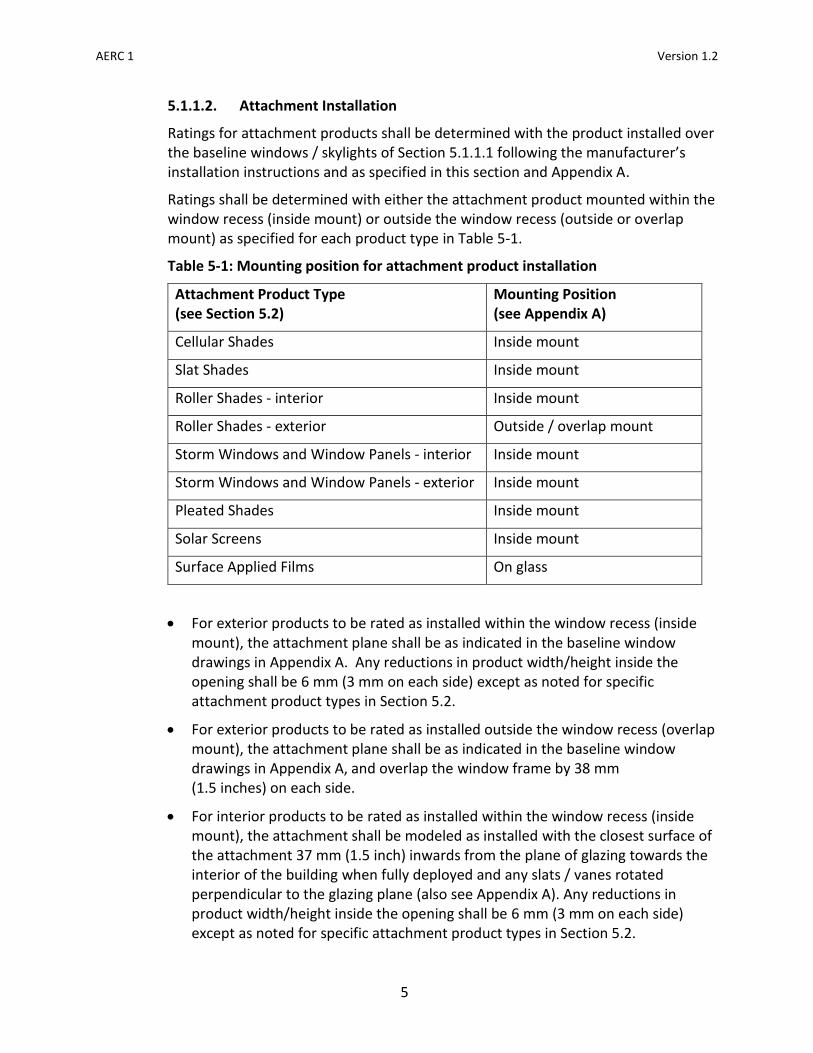
Table 5-1: Mounting position for attachment product installation
Attachment Product Type (see Section 5.2)
Mounting Position (see Appendix A)
Cellular Shades Inside mount
Slat Shades Inside mount
Roller Shades - interior Inside mount
Roller Shades - exterior Outside / overlap mount
Storm Windows and Window Panels - interior Inside mount
Storm Windows and Window Panels - exterior Inside mount
Pleated Shades Inside mount
Solar Screens Inside mount
Surface Applied Films On glass
For exterior products to be rated as installed within the window recess (inside mount), the attachment plane shall be as indicated in the baseline window drawings in Appendix A. Any reductions in product width/height inside the opening shall be 6 mm (3 mm on each side) except as noted for specific attachment product types in Section 5.2.
For exterior products to be rated as installed outside the window recess (overlap mount), the attachment plane shall be as indicated in the baseline window drawings in Appendix A, and overlap the window frame by 38 mm (1.5 inches) on each side.
For interior products to be rated as installed within the window recess (inside mount), the attachment shall be modeled as installed with the closest surface of the attachment 37 mm (1.5 inch) inwards from the plane of glazing towards the interior of the building when fully deployed and any slats / vanes rotated perpendicular to the glazing plane (also see Appendix A). Any reductions in product width/height inside the opening shall be 6 mm (3 mm on each side) except as noted for specific attachment product types in Section 5.2.
AERC 1 Version 1.2
6
For interior products to be rated as installed outside the window recess (overlap mount), the attachment shall be modeled as installed on the head/jambs/sill as indicated in the baseline window drawings in Appendix A, and overlap the window frame by 38 mm (1.5 inches) on each side.
Where installation according to these dimensions is precluded by physical constraints, the mounting distance between the attachment product and the glazing plane may be modified to accommodate the attachment product, extending the head / jambs / sills if necessary. Any variations in these dimensions shall be recorded.
Where ratings are determined with the attachment product mounted to the surrounding building materials (e.g. brickmold, interior trim) rather than directly to the baseline window frame or glazing, these surrounding materials shall be modeled as coniferous wood (k = 0.081 Btu/hr-ft-F) as shown in Appendix A.
Any additional specifications regarding installation for specific attachment product types are included in Section 5.2.
5.1.1.3. Environmental and Boundary Conditions
The following standard environmental and boundary conditions shall be used:
For U-factor,
Tinside = 21°C (69.8°F)
ASHRAE / NFRC inside convection model in the currently approved Lawrence Berkeley National Laboratory WINDOW and THERM software tools
Effective inside room temperature Trm,inside = Tinside
Effective room emissivity = 1.0
Toutside = -18°C (-0.4°F)
ASHRAE / NFRC outside convection model with exterior wind speed = 5.5 m/s (convection coefficient hc=26 W/m2K)
Effective sky temperature Tsky = Toutside
Effective sky emissivity = 1.0
Direct solar radiation Is = 0 W/m2
For SHGC,
Tinside = 24°C (75.2°F)
ASHRAE / NFRC inside convection model in the currently approved Lawrence Berkeley National Laboratory WINDOW and THERM software tools
Effective inside room temperature Trm,inside = Tinside
Effective room emissivity = 1.0
Toutside = 32°C (89.6°F)
ASHRAE / NFRC outside convection model with exterior wind speed = 2.75 m/s (convection coefficient hc=15 W/m2K)
Effective sky temperature Tsky = Toutside

AERC 1 Version 1.2
7
Effective sky emissivity = 1.0
Direct solar radiation Is = 783 W/m2
5.1.2. U-factor
5.1.2.1. Simulation procedures
The U-factor shall be calculated for each individual product (as determined for the appropriate product type in Section 5.2) installed in combination with Baseline Window B and, optionally, other baseline windows as specified in Section 5.1.1.1.
The U-factor for operable attachment products shall be calculated in both the fully open and fully closed positions, except as noted for specific product types in Section 5.2.
The U-factor shall be calculated using the currently approved Lawrence Berkeley National Laboratory WINDOW and THERM software tools in accordance with:
AERC 1.3, AERC Simulation Manual, 2017.
Default material and gas property libraries in the currently approved Lawrence Berkeley National Laboratory WINDOW and THERM software tools.
Optical and thermophysical property data included in the latest published version of the IGDB and CGDB.
Attachment installation details of Section 5.1.1.2.
Environmental and boundary conditions of Section 5.1.1.3.
Any additional requirements in Section 5.2 for the applicable product type.
Lift and control cords as well as discrete mounting hardware and operating components that do not extend along more than 50% of the full length or width of the attachment product may be ignored. This includes components such as but not limited to screws, bolts, brackets, latches, handles, clutches, cord locks, control rods, and end caps.
5.1.2.2. Test Option
For attachment products that cannot be simulated according to Section 5.1.2.1, the U-factor may be physically tested with the product installed in combination with Baseline Window B as specified in AERC 1.2. The U-factor for operable attachment products shall be tested in both the fully open and fully closed positions, except as noted for specific product types in Section 5.2. If the U-factor is not or cannot be determined in accordance with AERC 1.2, the fenestration attachment shall be assigned a U-factor the same as Baseline Window B without any attachment.

AERC 1 Version 1.2
8
5.1.3. Solar Heat Gain Coefficient
5.1.3.1. Simulation procedures
The SHGC shall be calculated for each individual product (as determined for the appropriate product type in Section 5.2) installed in combination with Baseline Window B and, optionally, other baseline windows as specified in Section 5.1.1.1.
The SHGC for operable attachment products shall be calculated in both the fully open and fully closed positions, except as noted for specific product types in Section 5.2.
The SHGC shall be calculated using the currently approved Lawrence Berkeley National Laboratory WINDOW and THERM software tools in accordance with:
AERC 1.3, AERC Simulation Manual, 2017.
Default material and gas property libraries in the currently approved Lawrence Berkeley National Laboratory WINDOW and THERM software tools.
Optical and thermophysical property data included in the latest published version of the IGDB and CGDB.
Attachment installation details of Section 5.1.1.2.
Environmental and boundary conditions of Section 5.1.1.3.
Any additional requirements in Section 5.2 for the applicable product type.
Lift and control cords as well as discrete mounting hardware and operating components that do not extend along more than 50% of the full length or width of the attachment product may be ignored. This includes components such as but not limited to screws, bolts, brackets, latches, handles, clutches, cord locks, control rods, and end caps.
5.1.3.2. Test Option
For attachment products that cannot be simulated according to Section 5.1.3.1, the SHGC may be physically tested with the product installed in combination with Baseline Window B as specified in AERC 1.2. The SHGC for operable attachment products shall be tested in both the fully open and fully closed positions, except as noted for specific product types in Section 5.2. If the SHGC is not or cannot be determined in accordance with AERC 1.2, the fenestration attachment shall be assigned a SHGC of “ND” for “not determined”.
5.1.4. Visible Transmittance
5.1.4.1. Simulation procedures
The VT shall be calculated for each individual product (as determined for the appropriate product type in Section 5.2) installed in combination with Baseline Window B and, optionally, other baseline windows as specified in Section 5.1.1.1.

AERC 1 Version 1.2
9
The VT for operable attachment products shall be calculated in both the fully open and fully closed positions, except as noted for specific product types in Section 5.2.
The VT shall be calculated using the currently approved Lawrence Berkeley National Laboratory WINDOW and THERM software tools in accordance with:
AERC 1.3, AERC Simulation Manual, 2017.
Default material and gas property libraries in the currently approved Lawrence Berkeley National Laboratory WINDOW and THERM software tools.
Optical and thermophysical property data included in the latest published version of the IGDB and CGDB.
Attachment installation details of Section 5.1.1.2.
Environmental and boundary conditions of Section 5.1.1.3.
Any additional requirements in Section 5.2 for the applicable product type.
Lift and control cords as well as discrete mounting hardware and operating components that do not extend along more than 50% of the full length or width of the attachment product may be ignored. This includes components such as but not limited to screws, bolts, brackets, latches, handles, clutches, cord locks, control rods, and end caps.
5.1.4.2. Test Option
For attachment products that cannot be simulated according to Section 5.1.4.1, the VT may be physically tested with the product installed in combination with Baseline Window B as specified in AERC 1.2. The VT for operable attachment products shall be tested in both the fully open and fully closed positions, except as noted for specific product types in Section 5.2. If the VT is not or cannot be determined in accordance with AERC 1.2, the fenestration attachment shall be assigned a VT of “ND” for “not determined”.
5.1.5. Air Leakage
The air leakage of storm windows and window panels shall be tested in accordance with the procedures of AERC 1.2. Air leakage testing for other fenestration attachment product types is optional.
Operable attachment products shall be tested in the fully closed position.
5.2. Specific Product Types
This section contains additional details, variations, and requirements that apply to specific product types, including the definition of characteristics that distinguish individual products within each product type.
Performance properties shall be calculated in the “fully open” and “fully closed” positions in accordance with Section 5.1 as defined for each product type below. Informative Note: Determination of U, SHGC, and VT performance properties in other positions (states of

AERC 1 Version 1.2
10
deployment, slat angles, etc.) is not required by this standard, but may be required for certain product types for use in AERC 2 for calculation of EPh and EPc.
5.2.1. Cellular Shades
Cellular shade product lines include fenestration attachments incorporating a cellular construction made from fabric or other materials joined together to form cells that trap air.
5.2.1.1. Individual Products
Individual products for which distinct performance properties shall be determined are distinguished by differences in one or more of the following characteristics:
Cell count (e.g. single cell, double cell, triple cell, full cell within a cell, split cell within a cell, etc.)
Nominal cell size
Nominal cell shape (e.g. square, hexagonal, asymmetric pentagonal, custom shape drawn in THERM, etc.)
Cell fabric / material type, including multiple / different materials on cell front, back, or interior
Rail height and depth (head, mid, bottom, and side rails)
Rail material (head, mid, bottom, and side rails)
Products incorporating edge tracks or edge seals
Cell orientation (e.g. vertical vs. horizontal)
Interior vs. exterior use
Products with different paints, colors, or finishes for head/bottom rails shall not be considered different individual products. For simulation of performance properties, a default solar absorptance of 0.3 shall be used for the head / bottom rails.
5.2.1.2. Product Grouping
Individual products may be grouped and represented by a single set of performance properties determined for the group leader as designated below. Individual products may be grouped that include:
Side lengths within the following ranges, provided all products within the group have the same cell fabric / material type: less than 14 mm (9/16 in), or greater than or equal to 14 mm (9/16 in).

AERC 1 Version 1.2
11
Side length is determined as shown below:
For products combined in groups with side lengths < 14 mm (< 9/16 in), the product with the smallest side length shall be the group leader used to represent the group.
For products combined in groups with side lengths ≥ 14 mm (≥ 9/16 in), the product with the largest side length shall be the group leader used to represent the group.
Cell materials that may be grouped in accordance with AERC 1.1.
5.2.1.3. Product Positions and Other Rules
For cellular shades, when calculating performance properties in accordance with Section 5.1,
“fully closed” shall mean deployed to cover the window opening to the fullest extent allowed by the attachment product design (as appropriate for the specific product: fully deployed until the attachment touches the surface of the base window, the maximum extent of the attachment hangs freely, or the attachment is in line with the base window's outermost bottom frame edge as shown in Appendix A), and
“fully opened” shall mean retracted as far as possible to cover the window opening to the smallest extent allowed by the attachment product design.
5.2.2. Slat Shades
Slat shade product lines include fenestration attachments incorporating horizontal or vertical vanes or slats that can be both tilted and retracted. Other common terms include venetian blinds, mini-blinds, and vertical louvers. Horizontally-oriented products have vanes suspended above each other by cords, tapes, or other means. Vertically-oriented products have vanes hanging vertically adjacent to
each other. Vanes may be overlapping or non-overlapping. These products are distinct from other window attachments as having two degrees of freedom in their operation (i.e., retraction and slat angle).

AERC 1 Version 1.2
12
5.2.2.1. Individual Products
Individual products for which distinct performance properties shall be determined are distinguished by differences in one or more of the following characteristics:
Slat width
Slat thickness
Slat curvature and shape (S-shape, crown shape, etc.)
Overlapping vs. non-overlapping slats
Slat material type, including different perforation patterns
Multiple materials on slat front and back
Horizontal vs. vertical vanes
Interior vs. exterior use
Products with different paints, colors, or finishes for head/bottom rails shall not be considered different individual products. For simulation of performance properties, a default solar absorptance of 0.3 shall be used for the head / bottom rails.
5.2.2.2. Product Grouping
Individual products may be grouped and represented by a single set of performance properties determined for the group leader as designated below. Individual products may be grouped that include:
Slat width increments within 6 mm (0.25 in). The product with the smallest slat width shall be the group leader used to represent the group.
Slat thickness increments within 0.5 mm (0.02 in). The product with the smallest slat thickness shall be the group leader used to represent the group.
Slat materials that may be grouped in accordance with AERC 1.1.
5.2.2.3. Product Positions and Other Rules
For slat shades, when calculating performance properties in accordance with Section 5.1,
“fully closed” shall mean deployed over the window opening with the slats or vanes rotated to cover the window opening and minimize light transmittance to the fullest extent allowed by the attachment product design (as appropriate for the specific product: fully deployed until the attachment touches the surface of the base window, the maximum extent of the attachment hangs freely, or the attachment is in line with the base window's outermost bottom frame edge as shown in Appendix A), and
“fully opened” shall mean retracted as far as possible and the slats or vanes rotated perpendicular to the plane of the window to cover the window opening to the smallest extent and maximize light transmittance to the largest extent allowed by the attachment product design.
AERC 1 Version 1.2
13
Informative note: Determination of U, SHGC, and VT performance properties in other positions (states of deployment, slat angles, etc.) is not required by this standard, but is required for calculation of EPh and EPc in AERC 2.
5.2.3. Roller Shades
Roller shade product lines include fenestration attachments incorporating a material that may be retracted and rolled onto a cylindrical shaft.
Note: This includes exterior solar screen materials retracted and rolled onto a cylindrical shaft. Fixed solar screens are considered under section 5.2.6.
5.2.3.1. Individual Products
Individual products for which distinct performance properties shall be determined are distinguished by differences in one or more of the following characteristics:
Shade material type
Multiple materials on shade front and back, inclusive of low-e or metallized coatings
Products incorporating fascia/cover boxes, edge tracks/side rails/edge seals/gaskets, and hem bars
Interior vs. exterior use
Products with different paints, colors, or finishes for fascia/cover boxes, edge tracks/ side rails/ edge seals/ gaskets, and hem bars shall not be considered different individual products. For simulation of performance properties, a default solar absorptance of 0.3 shall be used for fascia/cover boxes, edge tracks/side rails/edge seals/gaskets, and hem bars.
For exterior roller shades mounted outside the window recess and not overlapping the window glazing in the fully opened position, products fascia/cover boxes, edge tracks/side rails/edge seals/gaskets, and hem bars may be ignored, and shall not be considered different individual products.
5.2.3.2. Product Grouping
Individual products may be grouped and represented by a single set of performance properties determined for the group leader as designated below. Individual products may be grouped that include:
Shade materials that may be grouped in accordance with AERC 1.1.
For exterior roller shades only: different size fascia/cover boxes, edge tracks/side rails, and/or hem bars that are not permitted to be ignored in accordance with Section 5.2.3.1 may be grouped. A product configuration simulated with the smallest fascia/cover box size, smallest edge track/side rail/edge seal/gasket

AERC 1 Version 1.2
14
width, and smallest hem bar height shall be the group leader used to represent the group.
5.2.3.3. Product Positions and Other Rules
For roller shades, when calculating performance properties in accordance with Section 5.1,
“fully closed” shall mean deployed to cover the window opening to the fullest extent allowed by the attachment product design (as appropriate for the specific product: fully deployed until the attachment touches the surface of the base window, the maximum extent of the attachment hangs freely, or the attachment is in line with the base window's outermost bottom frame edge as shown in Appendix A), and
“fully opened” shall mean retracted as far as possible to cover the window opening to the smallest extent allowed by the attachment product design.
5.2.4. Storm Windows and Window Panels
Storm window and window panel product lines include fenestration attachments incorporating a solid material that is mounted (usually in a frame) coplanar over existing fenestration. Products may be fixed or operable.
5.2.4.1. Individual Products
Individual products for which distinct performance properties shall be determined are distinguished by differences in one or more of the following characteristics:
Glazing material type (glass, polymeric)
Glazing coatings, films, tints
Glazing thickness
Number of glazing layers
Fixed vs. operable configurations (single hung, double hung, other)
Frame material types
Frame profiles
Interior vs. exterior use
Products with different paints, colors, or finishes for frames / sashes shall not be considered different individual products. For simulation of performance properties, a default solar absorptance of 0.3 shall be used for the frame / sash.

AERC 1 Version 1.2
15
5.2.4.2. Product Grouping
Individual products may be grouped and represented by a single set of performance properties determined for the group leader as designated below. Individual products may be grouped that include:
Non-tinted glazing thickness increments within the following ranges, provided all glazing for products within the group has the same surface applied coating or film (or none): ≤ 3.2 mm (≤ 1/8 in) > 3.2 to ≤ 13 mm (> 1/8– ≤ 1/2 in) > 13 mm (> 1/2 in) Within each range, the product with the smallest thickness shall be the group leader used to represent the group.
5.2.4.3. Product Positions and Other Rules
For operable storm windows and window panels, performance properties shall be calculated in the fully closed position.
As specified in Appendix A, for operable horizontal sliding products, the aspect ratio of the standardized baseline windows in Appendix A shall be reversed (1500 mm width x 1200 mm height, in place of 1200 mm width x 1500 mm height).
A horizontal sliding product may be grouped with the corresponding vertical sliding product provided each performance property (U, SHGC, VT, AL) does not vary more than 10%. The performance properties of the product with the higher U-factor shall be used to represent the group.
Insect screens may be omitted when determining performance properties for storm windows and window panels.
For exterior storm windows and window panels to be rated as installed within the window recess (inside mount), any reductions in product width/height inside the opening shall be 3 mm (half on each side).
For interior storm windows and window panels to be rated as installed within the window recess (inside mount), the storm window / panel and its associated seals shall fill the opening.
5.2.5. Pleated Shades
Pleated shade product lines include fenestration attachments incorporating a single layer of a pleated material.

AERC 1 Version 1.2
16
5.2.5.1. Individual Products
Individual products for which distinct performance properties shall be determined are distinguished by differences in one or more of the following characteristics:
Pleat width
Shade material type
With added liner
Multiple materials on shade front and back
Products incorporating edge tracks or edge seals
Horizontal vs. vertical operation
Interior vs. exterior use
Products with different paints, colors, or finishes for head/bottom rails shall not be considered different individual products. For simulation of performance properties, a default solar absorptance of 0.3 shall be used for the head / bottom rails.
5.2.5.2. Product Grouping
Individual products may be grouped and represented by a single set of performance properties determined for the group leader as designated below. Individual products may be grouped that include:
Pleat widths within 6 mm (0.25 in) where pleat width is the distance between fold creases. The product with the smallest pleat width shall be the group leader used to represent the group.
Shade materials that may be grouped in accordance with AERC 1.1.
5.2.5.3. Product Positions and Other Rules
For pleated shades, when calculating performance properties in accordance with Section 5.1,
“fully closed” shall mean deployed to cover the window opening to the fullest extent allowed by the attachment product design (as appropriate for the specific product: fully deployed until the attachment touches the surface of the base window, the maximum extent of the attachment hangs freely, or the attachment is in line with the base window's outermost bottom frame edge as shown in Appendix A), and
“fully opened” shall mean retracted as far as possible to cover the window opening to the smallest extent allowed by the attachment product design.
5.2.6. Solar Screens
Solar screen product lines include fenestration attachments incorporating a screen material that is mounted (usually fixed in a frame) coplanar over existing fenestration.
Note: exterior solar screen materials retracted and rolled onto a cylindrical shaft shall be considered roller shade products.

AERC 1 Version 1.2
17
Exterior solar screen materials that are pleated to fold when the operating rail is moved shall be considered pleated shade products. See sections 5.2.3 and 5.2.5.
5.2.6.1. Individual Products
Individual products for which distinct performance properties shall be determined are distinguished by differences in one or more of the following characteristics:
Screen material type
Screen material opacity / openness
Number of screen layers
Frame material types
Frame profiles
Products with different paints, colors, or finishes for frames / sashes shall not be considered different individual products. For simulation of performance properties, a default solar absorptance of 0.3 shall be used for the frame / sash.
5.2.6.2. Product Grouping
Individual products may be grouped and represented by a single set of performance properties determined for the group leader as designated below. Individual products may be grouped that include:
Screen materials that may be grouped in accordance with AERC 1.1.
5.2.6.3. Product Positions and Other Rules
For solar screens in sliding panels, performance properties shall be calculated in the fully closed position.
5.2.7. Surface Applied Films
Surface applied film product lines include fenestration attachments incorporating a polymeric film adhered directly to the glazing in existing fenestration.
5.2.7.1. Individual Products
Individual products for which distinct performance properties shall be determined are distinguished by differences in one or more of the following characteristics:
Film material type (including different coatings, tints, multilayer compositions)
Film thickness
Interior vs. exterior use

AERC 1 Version 1.2
18
5.2.7.2. Product Grouping
Individual products may be grouped and represented by a single set of performance properties determined for the group leader as designated below. Individual products may be grouped that include:
Film materials that may be grouped in accordance with AERC 1.1.
5.2.7.3. Product Positions and Other Rules
For surface applied films, performance properties in Section 5.1 shall be calculated only in the as-applied position with the film covering the entire glazing area.
5.3. Dynamic Operation
For attachment products that can be operated such as raising, lowering, opening, or closing blinds and shades, Sections 5.1 and 5.2 determine the U-factor, SHGC, and VT under a specific set of environmental conditions and pre-specified positions: when the attachment is fully open and fully closed. These products may also be manually operated or automatically operated (automated) in different positions in a dynamic manner in response to environmental conditions, date and time, user commands, or other programming. This dynamic operation is not included in this standard – see AERC 2, which addresses annual energy performance ratings of fenestration attachment products.
6. Reporting
The following information shall be reported:
Product manufacturer
Product type, identification, drawings, and materials
Simulation and/or testing laboratory
Date of report
For each applicable baseline window (required Baseline Window B and any other optional baseline windows as specified in Section 5.1.1.1):
o U-factor, SHGC, and VT with the attachment product in the fully closed position as defined in Section 5.2.
o U-factor, SHGC, and VT with the attachment product in the fully open position as defined in Section 5.2. (Not required for storm windows and window panels, and solar screens.)
Air leakage in the fully closed position, when tested in accordance with Section 5.1.5. (Not required for all product types.)
Products grouped in accordance with Section 5.2, if applicable.
Any other information required for inclusion in the certified product database in accordance with AERC 100 and AERC 400 Appendix G (Approved Software and Manuals).
Calculated U-factor, SHGC, and VT shall be determined with the full precision in the approved software prior to rounding and reporting of final results.

AERC 1 Version 1.2
19
U-factor shall be rounded and reported to the nearest 0.05 W/m2K (0.01 Btu/hr·ft2·°F).
SHGC and VT shall be rounded and reported to two digits.
Tested air leakage shall be rounded and reported to the nearest 0.1 L/s/m2 (0.02 cfm/ft2).
All unit conversions and rounding shall be in accordance with IEEE/ASTM SI 10-2010.

AERC 1 Version 1.2
20
Appendix A - Baseline Windows
Note: Official THERM files of these windows may be downloaded from www.aercnet.org.
See Section 5.1.1.2 for further details on attachment installation. Where installation according to these dimensions is precluded by physical constraints, the mounting distance between the attachment product and the glazing plane may be modified to accommodate the attachment product, extending the head / jambs / sills if necessary. Any variations in these dimensions shall be recorded.
Baseline Window A – Nonmetal-framed, single pane
The performance of attachments over all nonmetal-framed windows with single pane glazing shall be represented by the following generic wood fixed window.
Size: 1200 mm width x 1500 mm height (exception: 1500 mm width x 1200 mm height for use with horizontal sliding storm windows and window panels)
6 mm clear glass (IGDB ID# 103, CLEAR_6.DAT)
Coniferous wood (k = 0.081 Btu/hr-ft-F)
3.625"
3.625"
3"
HEAD /
JAMBS
3"
0.25"
SILL
GENERIC WOOD FIXED WINDOW
Single Glazed
A.8
Interior overlap attachment mounted on this surface
Interior recessed (inside mount) attachment mounted on this surface so that closest surface of deployed attachment is 37 mm from the glazing plane.
Exterior overlap attachment inner surface on this plane
Exterior recessed (inside mount) attachment
inner surface on this plane 1.5”

AERC 1 Version 1.2
21
Baseline Window B – Nonmetal-framed, double pane
The performance of attachments over all nonmetal-framed windows with double pane glazing (without low-E glass) shall be represented by the following generic wood fixed window.
Size: 1200 mm width x 1500 mm height (exception: 1500 mm width x 1200 mm height for use with horizontal sliding storm windows and window panels)
3 mm clear glass (IGDB ID# 102, CLEAR_3.DAT)
½” air fill
Sealed IG (aluminum box spacer with loose fill dessicant, dual seal)
Coniferous wood (k = 0.081 Btu/hr-ft-F)
Interior overlap attachment mounted on this surface
Interior recessed (inside mount) attachment mounted on this surface so that closest surface of deployed attachment is 37 mm from the glazing plane.
Exterior overlap attachment inner surface on this plane
Exterior recessed (inside mount) attachment
inner surface on this plane
¾ x ¾”
blocks
2x8 dimensional wood (spruce-pine-fir)
1x1”
0.75”
1.5”
1/8” closed cell glazing tape or sealant applied to exterior stop prior to glazing
For operable exterior overlap attachments, fully deployed to this point, or the maximum extent that
hangs freely
For operable interior overlap attachments, fully deployed to this point, or the maximum extent that
hangs freely

AERC 1 Version 1.2
22
Interior overlap attachment mounted on this surface
Interior recessed (inside mount) attachment mounted on this surface so that closest surface of deployed attachment is 37 mm from the glazing plane.
Exterior overlap attachment inner surface on this plane
Exterior recessed (inside mount) attachment
inner surface on this plane
3.625"
3"
3.625"
3"
SILL
HEAD /
JAMBS
0.75"
GENERIC WOOD FIXED WINDOW
Dual Glazed
A.9
Baseline Window C – Nonmetal-framed, double pane low-E
The performance of attachments over all nonmetal-framed windows with double pane low-E glazing shall be represented by the following generic wood fixed window.
Size: 1200 mm width x 1500 mm height (exception: 1500 mm width x 1200 mm height for use with horizontal sliding storm windows and window panels)
Outer lite: 3 mm double silver low-e coating, #2 surface, clear glass (IGDB ID# 2011, LOE272-3.CIG)
Inner lite: 3 mm clear glass (IGDB ID# 102, CLEAR_3.DAT)
½” 90% argon fill
Aluminum dual sealed spacer (aluminum spacer with loose fill dessicant, hot melt butyl seal)
Coniferous wood (k = 0.081 Btu/hr-ft-F)
1.5”

AERC 1 Version 1.2
23
Baseline Window D – Metal-framed, single pane
The performance of attachments over all metal-framed windows with single pane glazing shall be represented by the following generic aluminum fixed window.
Size: 1200 mm width x 1500 mm height (exception: 1500 mm width x 1200 mm height for use with horizontal sliding storm windows and window panels)
3.5"
1"
0.75"
0.062"
SILL
HEAD /
JAMBS
0.25"
GENERIC ALUMINUM FIXED WINDOW
Single Glazed
A.10
6 mm clear glass (IGDB ID# 103, CLEAR_6.DAT)
Painted aluminum framed surrounded by coniferous wood (k = 0.081 Btu/hr-ft-F)
Interior overlap attachment mounted on this surface
Interior recessed (inside mount) attachment mounted on this surface so that closest surface of deployed attachment is 37 mm from the glazing plane.
Exterior attachment inner surface on this plane
Note: for attachment products with metal framing / rails, this assumes no direct contact between attachment and baseline window frame.
1.5”
3”

AERC 1 Version 1.2
24
Baseline Window E – Metal-framed, double pane
The performance of attachments over all metal-framed windows with double pane glazing (without low-E glass) shall be represented by the following generic aluminum fixed window.
Size: 1200 mm width x 1500 mm height (exception: 1500 mm width x 1200 mm height for use with horizontal sliding storm windows and window panels)
3 mm clear glass (IGDB ID# 102, CLEAR_3.DAT)
½” air fill
Aluminum dual sealed spacer (aluminum spacer with loose fill dessicant, hot melt butyl seal)
Painted aluminum framed surrounded by coniferous wood (k = 0.081 Btu/hr-ft-F)
Interior overlap attachment mounted on this surface
Interior recessed (inside mount) attachment mounted on this surface so that closest surface of deployed attachment is 37 mm from the glazing plane.
Exterior attachment inner surface on this plane
3.5"
1"
0.75"
0.062"
SILL
HEAD /
JAMBS
0.75"
GENERIC ALUMINUM FIXED WINDOW
Dual Glazed
A.11
Note: for attachment products with metal framing / rails, this assumes no direct contact between attachment and baseline window frame.
1.5”
3”

AERC 1 Version 1.2
25
Baseline Window F – Metal-framed, double pane low-E
The performance of attachments over all metal-framed windows with double pane low-E glazing shall be represented by the following generic aluminum fixed window.
Size: 1200 mm width x 1500 mm height (exception: 1500 mm width x 1200 mm height for use with horizontal sliding storm windows and window panels)
3.5"
1"
0.75"
0.062"
SILL
HEAD /
JAMBS
0.75"
GENERIC ALUMINUM FIXED WINDOW
Dual Glazed
A.11
Outer lite: 3 mm double silver low-e coating, #2 surface, clear glass (IGDB ID# 2011, LOE272-3.CIG)
Inner lite: 3 mm clear glass (IGDB ID# 102, CLEAR_3.DAT)
½” 90% argon fill
Aluminum dual sealed spacer (aluminum spacer with loose fill dessicant, hot melt butyl seal)
Painted aluminum framed surrounded by coniferous wood (k = 0.081 Btu/hr-ft-F)
Interior overlap attachment mounted on this surface
Interior recessed (inside mount) attachment mounted on this surface so that closest surface of deployed attachment is 37 mm from the glazing plane.
Exterior attachment inner surface on this plane
Note: for attachment products with metal framing / rails, this assumes no direct contact between attachment and baseline window frame.
1.5”
3”


![Aerc%20 Presentation[1]](https://img.pdfslide.us/doc/110x75/558650dcd8b42a1b498b4704/aerc20-presentation1.jpg)