Embed Size (px)
Citation preview

General rights Copyright and moral rights for the publications made accessible in the public portal are retained by the authors and/or other copyright owners and it is a condition of accessing publications that users recognise and abide by the legal requirements associated with these rights.
• Users may download and print one copy of any publication from the public portal for the purpose of private study or research. • You may not further distribute the material or use it for any profit-making activity or commercial gain • You may freely distribute the URL identifying the publication in the public portal
If you believe that this document breaches copyright please contact us providing details, and we will remove access to the work immediately and investigate your claim.
Downloaded from orbit.dtu.dk on: Jun 09, 2018
Aeration control by monitoring the microbiological activity using fuzzy logic diagnosisand control. Application to a complete autotrophic nitrogen removal reactor
Boiocchi, Riccardo; Mauricio Iglesias, Miguel; Vangsgaard, Anna Katrine; Gernaey, Krist V.; Sin, Gürkan
Published in:Journal of Process Control
Link to article, DOI:10.1016/j.jprocont.2014.10.011
Publication date:2015
Document VersionPeer reviewed version
Link back to DTU Orbit
Citation (APA):Boiocchi, R., Mauricio Iglesias, M., Vangsgaard, A. K., Gernaey, K., & Sin, G. (2015). Aeration control bymonitoring the microbiological activity using fuzzy logic diagnosis and control. Application to a completeautotrophic nitrogen removal reactor. Journal of Process Control, 30, 22-33. DOI:10.1016/j.jprocont.2014.10.011

Aeration control by monitoring the microbiological activity using fuzzy logic
diagnosis and control. Application to a complete autotrophic nitrogen removal
reactor
R. Boiocchi, M. Mauricio-Iglesias, A.K. Vangsgaard, K.V. Gernaey, G. Sin
CAPEC-PROCESS, DTU Chemical Engineering, Technical University of Denmark, DK-2800 Lyngby, Denmark,
(e-mail: [email protected]; [email protected]; [email protected]; [email protected]; [email protected])
ABSTRACT
Complete Autotrophic Nitrogen Removal (CANR) is a novel process where ammonia is converted to nitrogen gas by
different microbial groups. The performance of the process can be compromised by an unbalanced activity of the biomass
caused by disturbances or non-optimal operational conditions. This contribution describes the development of a fuzzy-logic
based system for both diagnosis and control of a CANR reactor. Based on a combination of measurements of the nitrogen
species concentration in the influent and in the effluent on the one hand, and insights into the activities of three distinctive
microbial groups on the other hand, the diagnosis provides information on: nitritation, nitratation, anaerobic ammonium
oxidation and overall autotrophic nitrogen removal. These four results give insight into the state of the process and are used
as inputs for the controller that manipulates the aeration to the reactor.
The diagnosis tool was first evaluated using 100 days of real process operation data obtained from a lab-scale single-stage
autotrophic nitrogen removing reactor. This evaluation revealed that the fuzzy logic diagnosis is able to provide a realistic
description of the microbiological state of the reactor with process engineering insight analysis. An evaluation of both the
diagnosis tool and the controller was done by simulating a disturbance in the influent concentration. High and steady
nitrogen removal efficiency was achieved thanks to the diagnosis and control system. Finally, development of the diagnosis
and control as two independent systems provided further insight into the operation performance, gives transparency
towards the operator and makes the system flexible for future maintenance or improvements.
Keywords: Fuzzy-logic; bioreactor control; bioprocess diagnosis; anammox; inference system; nitrogen removal.
ABBREVIATIONS
AOB Ammonia-Oxidizing Bacteria
AnAOB Anaerobic Ammonia-Oxidizing Bacteria
CANR Complete Autotrophic Nitrogen Removal
ER Exchange Ratio
FIS Fuzzy Inference System
FLC Fuzzy-Logic Control
FLD Fuzzy-Logic Diagnosis
HB Heterotrophic Bacteria
MF Membership Function
MV Manipulated Variable
NOB Nitrite-Oxidizing Bacteria
SBR Sequencing Batch Reactor
TN Total Nitrogen
1. INTRODUCTION
Monitoring microbial activity is essential for achieving high control performances in biological reactors. Advances in
molecular tools based on omics technology (genomics, metabolomics, etc...) provide a qualitative assessment of the activated
sludge microbial community structure with its diverse functions [1]. These measurements are however off-line, tedious, time-
intensive, expensive and not able to fulfil the actual needs of most monitoring and control applications. In addition, due to the
presence of interacting microbial groups many challenges arise when trying to estimate the microbial activity in a mixed-

culture bioreactor. Hence the information given by the few sensors usually implemented in a bioreactor needs to be expanded
with observers or other state-estimation tools in order to infer the state of the microbial groups. When first principle models
of the microbial kinetics are not available or mismatch significantly with the reality, expert-knowledge about a process
system can represent a useful alternative for the development of control strategies. The so-called “fuzzy-logic inference
system” (FIS) is a means to exploit this knowledge for control strategy development [2,3]. Since its control laws are
expressed in linguistic rather than mathematical expressions, FISs are intrinsically easy to understand and to adapt in
function of control performance requirements. Moreover, FISs have been shown to enable integrating quantitative
mechanistic knowledge with qualitative expert knowledge, making it suitable for processes that are still in the development
stage. Previous applications of FISs in wastewater treatment (WWT) include the control of activated sludge processes [4, 13],
digesters [11] or improving disturbance rejection [6].
The so-called Complete Autotrophic Nitrogen Removal (CANR) is a novel process that has shown its usefulness for the
side-stream treatment of reject water from anaerobically treated sludge dewatering or landfill leachate [4–6]. The CANR
process performs the conversion of ammonium (NH4+) to dinitrogen (N2) through the activity of ammonia-oxidizing bacteria
(AOB) and anaerobic ammonia-oxidizing bacteria (AnAOB) [4,5]. AOB partially convert NH4+ to nitrite (NO2
-) with oxygen
(O2) as electron acceptor and AnAOB oxidize the remaining fraction of NH4+ by reducing the AOB-produced NO2
- [4,7–9].
In this process, a minor fraction of nitrate (NO3-) is produced. Well-known advantages of the CANR process are: reduction of
O2 supply, no need for organic biodegradable carbon addition and negligible sludge production [5]. CANR can be
accomplished in a single reactor, where AOB and AnAOB work simultaneously, or in a two-stage configuration designed to
have the aerobic AOB-mediated process, namely nitritation, preceding the AnAOB-mediated process. The performance of a
single-stage CANR can be seriously compromised due to disturbances as well as operating conditions leading to unbalanced
activity of the biomass. For example, a significant activity of nitrite-oxidizing bacteria (NOB), a class of autotrophic
microorganisms converting NO2- to nitrate (NO3
-), reduces the total nitrogen (TN) removal efficiency, since NO3
- requires a
significant amount of readily degradable organic carbon and the presence of heterotrophic bacteria (HB) to be converted to
N2.
Ensuring a balanced microbiological activity during CANR is therefore central in order to achieve a good and steady
performance. Since many microbial processes take place simultaneously resulting in dependencies and competition between
the microbial groups, linear controllers using constant set point values for dissolved oxygen, O2 reduction potential, N
species or pH alone may not be enough to ensure balanced microbial community activities and therefore performance
stability [10–12]. Too high O2 concentrations inhibit the AnAOB activity and enhance the undesired activity of NOB. On the
other hand, too low O2 supply leads to low aerobic AOB activity [4,8]. Therefore, a diagnosis of the microbiological
operation is needed to establish the appropriate control action.
The present work is a comprehensive extension and analysis of the work presented at the CAB/DYCOPS conference in
2013 [13]. The main additions made are: (i) a structured methodology and in-depth description of the work flows underlying
the development of a fuzzy-logic diagnosis and fuzzy-logic controller. In addition, the control block diagram indicating the
data-flow and information flow hierarchy is presented, (ii) detailed analysis and validation of the diagnosis tool with
experimental data and process engineering insights, (iii) control performance evaluation under more challenging disturbances
and conditions. The objective of this work is to develop a fuzzy-logic diagnosis (FLD) and a fuzzy-logic control (FLC) with
the objective of achieving high and steady TN removal in a single-stage CANR reactor with granular sludge. The FLD will
provide information regarding the activity of the biomass as an input to the FLC. Diagnosis and control will be developed
independently in order to achieve transparency on the input information given to the controller, and flexibility in case of
needed control performance improvement and feasibility for the implementation of the knowledge by the operator.
The paper is organised as follows: first the mathematical model of a lab-scale CANR reactor and the modelling of generic
FIS are presented. Afterwards, the development of the FLD and FLC tools is explained. The fuzzy-logic diagnosis
performance will first be evaluated on the basis of the consistency of the outputs produced and of their capability of
realistically describing the actual situation of the biomass during 100 days of a lab-scale CANR operation. Finally, both the
FLD and the FLC are evaluated by simulation of a disturbance in the nitrogen load to the reactor, in the form of a change in
the incoming ammonium concentration.
2. MATERIALS AND METHOD
The FLD and FLC system developed were implemented using the fuzzy logic toolbox of MATLAB R2013 (The
MathWorks, Natick, MA). The developed FLD and FLC were then coupled to a process model built in Simulink. The
process model consists of the description of the physical and biochemical processes occurring in a lab-scale CANR reactor.
In this section, first a brief description regarding the mathematical model used and the physical configuration of the reactor
are provided. Afterwards an overview of the generic work done by a fuzzy-logic inference system will be shown.

2.1 Mathematical model and physical configuration of the reactor
The mathematical model employed in this work describes a granular based single-stage CANR sequencing batch
reactor (SBR) shown in Figure 1. The model developed and described in detail by Vangsgaard et al. [14] is shortly
described here for the sake of completeness. It consists of mass balance equations for each soluble and particulate
compound considered in the model. The main assumptions included are: (a) the transfer of soluble compounds
within the granule occurs only by diffusion (equation (1)) and (b) the transport of particulate compounds occurs
only by advection (equation (2)). The bulk of the reactor is assumed to be completely mixed, which results in
equation (3).
𝜕𝑆𝑖
𝜕𝑡= 𝐷𝑖 ∙
1
𝑧2∙
𝜕
𝜕𝑧(𝑧2 ∙
𝜕𝑆𝑖
𝜕𝑧) + 𝑟𝑖 (1)
𝜕𝑋𝑖
𝜕𝑡= −
𝜕(𝑋𝑖 ∙ 𝑢𝐹)
𝜕𝑧+ 𝑟𝑖 (2)
𝑑𝐶𝑖
𝑑𝑡=
𝑄𝑖𝑛 ∙ 𝐶𝑖,𝑖𝑛 − 𝑄𝑜𝑢𝑡 ∙ 𝐶𝑖,𝑏𝑢𝑙𝑘 − 𝑗𝑏𝑖𝑜,𝑖 ∙ 𝐴𝑏𝑖𝑜
𝑉+ 𝑟𝑖 (3)
In equations (1-3) Di is the diffusivity of compound i, z is the radial direction in spherical coordinates, Si is the
concentration of soluble compound i, ri is the reaction rate for compound i, Xi is the concentration of particulate
compound i, uF is the biofilm net growth velocity, Ci is the concentration of generic compound i (it applies to both
soluble and particulate compounds), Qin and Qout are the in- and outflow respectively, jbio,i is the flux in and out the
biofilm and V is the reactor volume. The reaction rate expression is deduced from the Petersen matrix reported in
Vangsgaard [15]. The distributed model has 12 state variables, namely: AOB, AnAOB, NOB, heterotrophic
bacteria (HB), total ammonia nitrogen, total nitrite nitrogen, dissolved oxygen, nitrate, dinitrogen, readily
biodegradable organic carbon, particulate organic material and particulate inert material. The modelled processes
are: the growth and decay of AOB, NOB and AnAOB, the aerobic growth of HB and the anoxic growth of HB
with both NO2- and with NO3
- as electron acceptor, the decay of HB and the hydrolysis of organic suspended
solids.
The operation of the reactor is arranged according to cycles of 8-hour duration. Each cycle is structured according
to the following sequence of phases: anoxic feeding phase (10 minutes), alternate oxic/anoxic reaction phase (444
minutes), settling phase (6 minutes), decanting phase (10 minutes) and anoxic idle phase (10 minutes). The four-
litre reactor has a cylindrical shape. Perfect control of temperature (30°C) and pH (7.5) are assumed during the
operation. A synthetic influent was used characterized by a nominal ammonium concentration of 500 mg N.L-1
while the ratio between the volume leaving the reactor at the end of the cycle and the maximal liquid volume in
the reactor, namely the exchange ratio (ER), was maintained constant at 0.5. This resulted in a volumetric loading
rate to the system of 750 mg N L-1
d-1
.
Figure 1: Reactor configuration [15].
2.2 Fuzzy-logic Inference System Modelling
In this subsection a brief description about the generic operation of a FIS is presented.
Figure 2 shows the procedure according to which a generic FIS deduces the numerical values of its outputs (i.e.
crisp outputs) starting from a set of crisp inputs. As can be seen, this procedure can be divided into three main
subsequent operations:

I) Fuzzification: a crisp input (u) is converted into fuzzy inputs (𝑈) by the so-called “Fuzzifier”,
II) Fuzzy Inference: The “Fuzzy Inference Engine” infers the fuzzy outputs (𝑌) on the basis of the values
of 𝑈 through the rules from the “Fuzzy rule base”,
III) Defuzzification: the so-called “Defuzzifier” converts 𝑌 into a crisp output (y).
Figure 2: Simplified scheme of a fuzzy system [2].
For in-depth analyses about fuzzy system modelling, the work of Lababidi and Baker [2] should be consulted.
3. DEVELOPMENT OF FUZZY-LOGIC DIAGNOSIS AND CONTROL
As disclosed in the introduction, the aim of the present work is to develop a process-insight based control strategy for a
CANR system to achieve a high and steady TN removal efficiency by adjusting the plant operation on the basis of the
activity of the biomass. During the development of the control system, transparency and flexibility have also been
considered as important features to be achieved. With the term “transparency”, it is meant that the task of describing
the microbiological activity of the biomass can be carried out independently from the task of deciding the control
actions to be carried out. By delegating these two operations to two different tools it is possible to identify the
underlying cause i.e. a bottleneck that compromises the performance of the entire control system. Thus the design of
the tool giving a low performance can be changed without conceptually modifying the design of the other tool. For this
reason, the following two fuzzy-logic tools have been developed separately: a fuzzy-logic diagnosis (FLD), in charge
of diagnosing the current activity of the biomass in the system, and a fuzzy-logic control (FLC), in charge of deciding,
on the basis of the diagnosis results, the appropriate control actions to be taken. The procedures adopted are described
in subsections 3.1 and 3.2.
3.1 Development of Fuzzy-Logic Diagnosis
Identification of the input and output variables. Based on stoichiometric analysis of CANR performance and on
knowledge including a relationship between process performance and the microbiological state of the system, a
decision tree for facilitating start-up of single-stage CANR systems was developed by Mutlu et al. [16]. As can be
seen in Figure 3, the tree provides a screening of the activity of the CANR system on the basis of the values of the
following parameters (defined in Figure 3 within rhombus-shaped boxes):
Total nitrogen variation: ∆TN = TNeff − TNin (4)
Ratio of NH4+ consumed to TN removed: RAmmTot = |
∆(NH4+ − N)
∆TN| (5)
Ratio of NO2− produced to NH4
+ consumed: RNitAmm = |∆(NO2
− − N)
∆(NH4+ − N)
| (6)
𝒖
𝑼 𝒀
𝒚

Ratio of NO3− produced to TN removed: RNatTot = |
∆(NO3− − N)
∆TN| (7)
NH4+ removal efficiency: Reff = 1 −
(NH4+ − N)eff
(NH4+ − N)in
(8)
Ratio between NO2− and NH4
+ in the effluent: RNitAmm,eff =(NO2
− − N)eff
(NH4+ − N)eff
(9)
The variations used in the above equations refer to the difference between the specific nitrogen compound
concentration in the effluent at the end of the cycle and the one in the influent at the beginning of the same cycle.
Total nitrogen (TN) is given by the sum of nitrate, nitrite and ammonium nitrogen. Thus ∆TN in equation (4) is
representing the nitrogen gas produced and the nitrogen contained in the biomass in the reactor [16].
An in-depth description of the meaning of the diagnosis variables in equations (5-9) and of their role in diagnosing
the activity of the system biomass is provided in Mutlu et al. [16]. However, for the sake of completeness, a brief
overview is presented:
In equation (5) RAmmTot represents the amount of ammonium consumed with respect to the amount of TN removed.
1) In case RAmmTot is low, which means high conversion of ammonium into dinitrogen with respect to the amount
of ammonium removed, the balance of the microbial activity is further checked by the value of Reff which
enables knowing if there is a fair activity of AOB.
a. If Reff is higher than 80%, the activity of the biomass is considered to be balanced.
b. Otherwise, a low AOB activity is detected.
2) If the value of RAmmTot is too high, i.e. ∆TN is too low with respect to NH4+ removed, the activity is defined as
unbalanced. As a matter of fact, it is possible that, although NH4+ is significantly removed, the activity of
AnAOB is compromised and/or excessive NOB concentrations are formed and/or the activity of AOB is too
high. Each of these three conditions can be the cause of low ΔTN over ΔNH4+. To discriminate whether the
imbalanced activity detected through RAmmTot is given by NOB presence or not, the ratio of NO3- produced
over ΔTN, represented in equation (7), is used. As a matter of fact, the parameter quantifies the amount of
NO3- produced over the total nitrogen removed. The higher NOB activity is, the larger RNatTot is. According to
the values of RNatTot, two scenarios can be identified:
a. if RNatTot is lower than 0.16 g NO3--N.g
-1 N-TN (meaning no significant presence of NOB), RNitAmm is
then used to ascertain whether a nitrite accumulation is occurring or not as follows:
i. If RNitAmm is low then a limited activity of AOB is diagnosed because the variable represents
the ratio between nitrite produced and the ammonium consumed.
ii. if RNitAmm is positive, then a problem of nitrite accumulation is detected because in a single-
stage CANR reactor the nitrite produced by AOB should be subsequently consumed by
AnAOB. In this case either too much nitritation or a limited activity of AnAOB would be
the cause. To discriminate between these two situations the value of RNitAmm,eff (equation
(9)), which defines the ratio between the NO2- and NH4
+ in the effluent, is used. In
particular, in case (ii.a) RNitAmm,eff is larger than 1.32, the fault of the imbalance is addressed
to an excessive activity of AOB, otherwise (ii.b) to a limitation in the AnAOB activity,
being that AOB produce NO2- while AnAOB consume it.

Legend:
Figure 3: Diagnosis tree, adapted from Mutlu et al. [16].
Input variable centring and scaling. Before passing the inputs to the fuzzifier, the variables calculated through
equations (5-9) were first centred and subsequently scaled. These two variable-handling procedures were
performed in order to help defining the membership functions (MFs) shown in the subsequent paragraph more
intuitively, thus allowing an easy implementation of the experience-acquired knowledge. As a matter of fact,
centring the diagnosis inputs by subtracting their respective cut-off values used in the diagnosis tree (within the
rhombus-shaped boxes in Figure 3) switches to “zero” the new cut-off value for all the variables. This is valid
expect for Reff, which was not centred in order to preserve its own physical meaning of efficiency. Once centred,
each variable was divided by a scaling factor. This served the purpose of making the numerical distributions of the
input values uniform. Thus the MFs of the different variables could have been defined symmetrically. As resulted
from these two operations, the variation range for all the crisp FIS inputs became [-1 1], apart from Reff whose
range remained [0 1].
Fuzzification. The membership functions for the input variables were chosen based on expert knowledge.
Following as example the successful applications by Comas et al. [17], Garcia et al. [18] and Yong et al. [19],
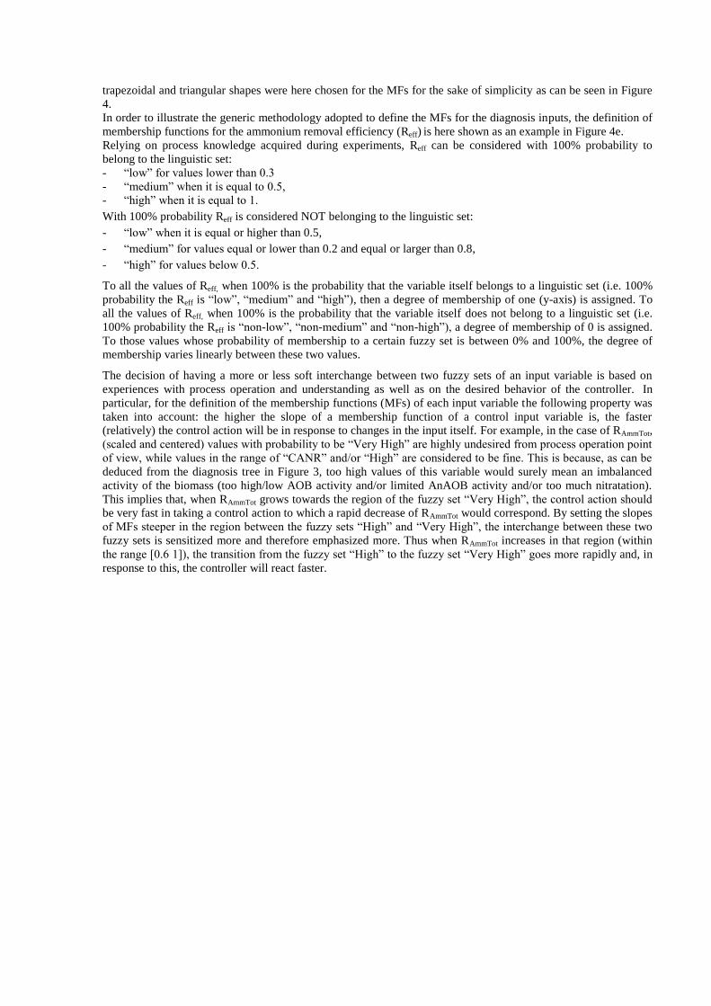
trapezoidal and triangular shapes were here chosen for the MFs for the sake of simplicity as can be seen in Figure
4.
In order to illustrate the generic methodology adopted to define the MFs for the diagnosis inputs, the definition of
membership functions for the ammonium removal efficiency (Reff) is here shown as an example in Figure 4e.
Relying on process knowledge acquired during experiments, Reff can be considered with 100% probability to
belong to the linguistic set:
- “low” for values lower than 0.3
- “medium” when it is equal to 0.5,
- “high” when it is equal to 1.
With 100% probability Reff is considered NOT belonging to the linguistic set:
- “low” when it is equal or higher than 0.5,
- “medium” for values equal or lower than 0.2 and equal or larger than 0.8,
- “high” for values below 0.5.
To all the values of Reff, when 100% is the probability that the variable itself belongs to a linguistic set (i.e. 100%
probability the Reff is “low”, “medium” and “high”), then a degree of membership of one (y-axis) is assigned. To
all the values of Reff, when 100% is the probability that the variable itself does not belong to a linguistic set (i.e.
100% probability the Reff is “non-low”, “non-medium” and “non-high”), a degree of membership of 0 is assigned.
To those values whose probability of membership to a certain fuzzy set is between 0% and 100%, the degree of
membership varies linearly between these two values.
The decision of having a more or less soft interchange between two fuzzy sets of an input variable is based on
experiences with process operation and understanding as well as on the desired behavior of the controller. In
particular, for the definition of the membership functions (MFs) of each input variable the following property was
taken into account: the higher the slope of a membership function of a control input variable is, the faster
(relatively) the control action will be in response to changes in the input itself. For example, in the case of RAmmTot,
(scaled and centered) values with probability to be “Very High” are highly undesired from process operation point
of view, while values in the range of “CANR” and/or “High” are considered to be fine. This is because, as can be
deduced from the diagnosis tree in Figure 3, too high values of this variable would surely mean an imbalanced
activity of the biomass (too high/low AOB activity and/or limited AnAOB activity and/or too much nitratation).
This implies that, when RAmmTot grows towards the region of the fuzzy set “Very High”, the control action should
be very fast in taking a control action to which a rapid decrease of RAmmTot would correspond. By setting the slopes
of MFs steeper in the region between the fuzzy sets “High” and “Very High”, the interchange between these two
fuzzy sets is sensitized more and therefore emphasized more. Thus when RAmmTot increases in that region (within
the range [0.6 1]), the transition from the fuzzy set “High” to the fuzzy set “Very High” goes more rapidly and, in
response to this, the controller will react faster.

Figure 4: Membership functions of FLD inputs: (a) RAmmTot, (b) RNatTot, (c) RNitAmm, (d) RNitAmm,eff and (e) Reff.
Fuzzy inference. The IF-THEN rules were deduced from the diagnosis tree in Figure 3. Look-up tables including
these rules are presented altogether in Table 1. The Mamdani-type inference was chosen for the sake of simplicity
as the definition of Sugeno-type inference rules requires too specific knowledge for the consequent part of the
rule. The rules have the same importance with each other. Hence the same weights were assigned to all the rules.
The implication method used when inferring from each rule a degree of membership for the related output
variables was the correlation-minimum while disjunctive was the aggregation method chosen in order to sum up
all the degrees of membership for the same output variables into one.
As outputs from this module, degrees of membership for each fuzzy set of each output are found.
Table 1: Fuzzy-logic diagnosis rules: (a) Output 1 = CANR performance index, (b) Output 2 = Nitritation, (c)
Output 3 = AnAOB activity and (d) Output 4 = Nitratation.
Legend: VH=Very High, H=High, M=Medium, L=Low VL=Very Low, NL=Non-Limited, L=Limited and AZ=Almost Zero.
(a)
↓Reff /RAmmTot → L H VH
H VH H L
M OK OK L
L L L L
(b)
IF [RAmmTot not Low] AND [RNatTol Low] AND
↓RNitAmm,ef /RNitAmm → VL L H VH
L VL L OK OK
H VL L H VH
(a) (b) (c)
(d) (e)

IF [RAmmTot =Low] AND
↓RAmmTot / REff → H F L
L OK L VL
(c)
IF [RAmmTot not Low] AND [RNatTol = Low] AND
↓RNitAmm,ef /RNitAmm → VL L H VH
L NL NL L L
H NL NL NL NL
IF [RAmmTot is Low] OR [RNatTol not Low], THEN [AnAOB activity= NL]
(d)
↓RNatTot /RAmmTot → L H VH
L AZ AZ AZ
H AZ L H
VH AZ H VH
Defuzzification. The MFs shown in Figure 5 have been used for the FLD outputs. Similarly to those used for
fuzzification, these functions were also defined with trapezoidal and triangular shapes. Theoretically the definition
of these MFs could be done arbitrarily since the variables at issue do not have a physical meaning but a quality-
descriptive one. However, to check the performance of the FLD, its outputs have to be interpreted easily. For this
purpose, low numerical values of CANR performance index, nitritation and nitratation (x-axis) belong to linguistic
sets indicating low performance and/or low activity. On the other hand, high numerical values of the same
variables were assigned to linguistic sets indicating high performance and/or high activity. The exception is the
variable “AnAOB activity” to which an intrinsic meaning of “AnAOB activity limitation” was attributed. In this
case, high numerical values are representative of higher limitation whereas low values represent low limitation. By
defining the membership functions for the FLD outputs in this way, the interpretation of the diagnosis
performance resulted intuitively.
The conversion of the degrees of membership (y-axis) for each FLD output found through the rules into a single
numeric (crisp) value (x-axis) was chosen to be performed according to the Centre-Of-Area method. This choice
was made in virtue of its characteristics of continuity and non-ambiguity mentioned in Helledoorn and Thomas
[20].

Figure 5: Membership functions for fuzzy-logic diagnosis outputs: CANR performance index (a), Nitritation (b),
AnAOB activity (c) and Nitratation (d).
3.2 Development of Fuzzy-Logic Control
Identification of the input and output variables. The fuzzy-logic control input variables correspond to the fuzzy-
logic diagnosis output variables as its work is to infer control actions on the basis of the diagnosed biological
activity. Thus the activity of aerobic AOB, AnAOB and NOB and CANR performance index are identified as
inputs. On the basis of their values, the fuzzy-logic control will infer the deviation of the manipulated variables
(MVs) chosen from their respective nominal values. In order to identify the MVs a degree of freedom analysis was
performed according to Larsson and Skogestad [21]. On the basis of this analysis the following four manipulated
variables were considered as potential candidates: the mixer, the electrical heating jacket, the air supply and the
exchange ratio (ER). The heating jacket is assumed to perfectly control the temperature. The mixer was not
considered as a suitable MV due to a lack of mechanistic knowledge relating the mixing conditions to the process
performance. ER was controlled at 0.5. For this reason the only MV chosen to control the process performance
metric was the air supply, modelled as the oxygen mass transfer coefficient (kLa). The deviation of this MV (ΔkLa)
represents therefore the actual output of the FLC.
Fuzzification. The same MFs used for the defuzzification in FLD (shown in Figure 5) were used to find the
probability of membership to the fuzzy sets for each input.
Fuzzy inference. Similarly to the FLD, also for this tool the Mamdani-type inference was used. The same
importance degree was attributed to all of the IF-THEN rules. Correlation-minimum and disjunction were the
methods chosen for the implication and aggregation operations respectively. Since the AnAOB activity is
intrinsically linked with balanced nitritation and nitratation, ensuring a balanced activity of AOB and NOB implies
ensuring a balanced AnAOB activity. Hence including rules for changes of the kLa in order to have balanced
nitritation and nitratation can be considered sufficient to avoid AnAOB limitation. Thus, in order not to overload
the control system with additional and superfluous rules, no direct rule linking kLa variation with AnAOB activity
was taken into account. In the following look-up table the list of control rules used is presented.
Table 2: Fuzzy-logic control rules.
Legend: Z=zero; PL=Positive Large, P=Positive, N=Negative; NL=Negative Large, VG=Very Good;
(a) (b)
(c) (d)

↓Nitritation/CANR index → VG OK M LOW
VL P P PL PL
L Z Z P P
M Z Z Z Z
H Z Z N N
VH N N NL NL
↓Nitratation/CANR index→ VG OK M LOW
AZ Z Z Z Z
L N N N N
H N NL NL NL
VH NL NL NL NL
Defuzzification. The MFs of the kLa deviation were shaped as trapezoidal and triangular as the MFs in the
diagnosis. In Figure 6 the MFs of this variable are depicted. Similarly to the FLD, the method used to deduce a
crisp value on the basis of the degrees of membership for each fuzzy sets of “kLa deviation” was the Centre-Of-
Area.
Figure 6: Membership functions of fuzzy-logic control output (kLa variation).
Output variable scaling. The crisp values obtained for kLa deviation from defuzzification are then scaled by
multiplying the values by 150 d-1
.
4. RESULTS AND DISCUSSION
The block diagram of the fuzzy logic diagnosis and control system implementation to control the CANR system is
given in Figure 7.

Figure 7: Structure of the fuzzy logic diagnosis and control system (FLD=Fuzzy-Logic Diagnosis, FLC=Fuzzy-Logic
Control, S=Sensors).
As can be seen in Figure 7, the concentration of ammonium is measured both in the influent and in the effluent along
with the effluent nitrite and nitrate concentrations. The sampling was done at the beginning of each cycle for the
compounds in the influent and at the end of each cycle for those in the effluent. In this context, measurement noises
were not taken into account assuming their negligible influence in the context of a fuzzy-logic control where the
measured (crisp) variables are handled in a fuzzified environment. The measured values obtained were then used to
calculate the FLD inputs, namely RAmmTot, RNitAmm, RNatTot, Reff and RNitAmm,eff. These inputs, after preliminary centring
and scaling, were then handed over to the FLD tool which inferred the CANR performance index, Nitritation, AnAOB
activity and Nitratation. At this point it is worth noting that the FLD outputs are called variables, although they have a
quality-descriptive meaning rather than a physical meaning. As a matter of fact, they depict altogether the
microbiological activity of the biological system. On the basis of their crisp values deduced by the FLD, the FLC is
then able to infer the variations of the manipulated variable (kLa) from their respective nominal values. This control
action takes place at the beginning of the reaction phase of the next cycle.
More in detail, the procedure according to which the proper control actions are calculated on the basis of the
measurements is summarized in the following sequential steps:
I. Calculation of the crisp values for the diagnosis input variables: parameters RAmmTot, RNatTot, RNitAmm, RNitAmm,eff and
Reff are calculated through equations (5-9) by using the measured concentration of nitrogen species in the liquid
phase,
II. Centring and scaling of the diagnosis input variables: the parameters calculated in I are centred according to their
respective cut-off values given in the tree-like scheme of Figure 3 and scaled,
III. Fuzzy-logic Diagnosis: crisp values for CANR performance index, Nitritation, AnAOB activity and Nitratation
are inferred on the basis of the crisp values of the centred and scaled RAmmTot, RNatTot, RNitAmm, RNitAmm,eff and Reff,
IV. Fuzzy-logic Control: crisp values for ΔkLa are inferred on the basis of crisp values for CANR performance index,
Nitritation, AnAOB activity and Nitratation given by III,
V. Scaling of Fuzzy-logic Control outputs: the crisp values of ΔkLa are multiplied by their respective nominal values.

VI. Calculation of the actual kLa as input to the reactor: Addition of the scaled ΔkLa to their respective nominal values
(i.e. kLa(t) = kLa0 + ΔkLa).
Step III, namely fuzzy logic diagnosis, can be further split up into the following sub-steps:
IIIA. Diagnosis fuzzification: the crisp scaled and centred inputs RAmmTot, RNatTot, RNitAmm, RNitAmm,eff and Reff are
converted into input fuzzy sets by means of the MFs shown in Figure 4,
IIIB. Diagnosis inference: the fuzzy outputs are generated from the corresponding input fuzzy sets on the basis of
the rules in Table 1,
IIIC. Diagnosis defuzzification: the fuzzy outputs (CANR performance index, Nitritation, AnAOB activity and
Nitratation) obtained in IIIB are then translated into numerical values for CANR performance index, Nitritation,
AnAOB activity and Nitratation through the Centre-of-Area method applied on the MFs shown in Figure 5.
Step IV, namely fuzzy logic control, can be further split up into the following sub-steps:
IVA. Controller fuzzification: the crisp values for CANR performance index, Nitritation, AnAOB activity and
Nitratation obtained from sub-step IIIC are converted into input fuzzy sets by means of the same MFs used for IIIC,
IVB. Controller inference: the fuzzy inputs obtained in IVA are transformed into control fuzzy outputs according to
the set of rules in Table 2,
IVC. Controller defuzzification: the controller fuzzy outputs (variation of kLa) are converted into their respective
crisp values by applying the Centre-of-Area method on the MFs shown in Figure 6.
Table 3 sums up the input and output variables of the diagnosis and control tools.
Table 3: Fuzzy-logic diagnosis inputs (a) and outputs (b) and control outputs (c)..
Since FLD and FLC are independent tools, it is possible to separately evaluate the performance of each model as will be
done in subsection 4.1 and 4.2.
4.1 Evaluation of the diagnosis tool
Since the control actions are based on the FLD outputs, a first check on the reliability of the outputs generated by the
FLD is performed. To this end, data obtained from 100-day experimentation on the lab-scale reactor described in
subsection 2.1 were used. It is noted that the data were obtained from a period where the system was operated in a
manual operating mode following the operation protocol given by Mutlu et al. [16]. Hence these data serve for the
purpose of evaluating the performance diagnosis module alone. In Figure 8, the effluent concentrations of the three
nitrogen species (i.e. ammonium, nitrate and nitrite) collected during the experiments and the related total nitrogen
removal efficiency are depicted. By using these data as inputs to the diagnosis module, the FLD outputs plotted in
Figure 9 are obtained.
(a)
FLD INPUT 1 FLD INPUT 2 FLD INPUT 3 FLD INPUT 4 FLD INPUT 5
RAmmTot RNitAmm RNatTot RNitAmm,eff Reff
(b)
FLD OUTPUT 1 FLD OUTPUT 2 FLD OUTPUT 3 FLD OUTPUT 4
CANR performance index Nitritation AnAOB activity Nitratation
(c)
FLC OUTPUT
ΔkLa

Figure 8: Input data set to FLD module: effluent nitrogen species concentration (on the left: NH4+
(red), NO3-
(green) and NO2- (blue)) and TN removal efficiency (on the right).
Figure 9: Output from FLD module: results of the fuzzy-logic diagnosis for 100 days.
As can be seen in Figures 8 and 9, the total duration of the experiment can be split up into four subsequent periods
identified on the basis of the different behaviours of the biomass: from the beginning of the experiment till day 40,
from day 40 till day 60, from day 60 till day 80 and from day 80 till the end.
By looking at Figure 9, the activity of the AnAOB is limited by high nitratation during the first period. This is
because, as revealed in Figure 9d, the NOB activity is so high that the availability of NO2- for AnAOB is
(a) (b)
(c) (d)
(a) (b)

significantly reduced. As a result of this undesired imbalance (i.e. the NO2- : NH4
+ ratio), the performance is
mostly unsatisfactory, as can be seen from the CANR performance index. By following the operation protocol in
manual mode, during the second period the O2 supply rate to the system was decreased. This operation helped
AOB to successfully outcompete or reduce the NOB activity in the system – a desirable condition for promoting
AnAOB activity and therefore achieving higher performance [16], as described by the CANR performance index.
During the subsequent period of time, as a consequence of low oxygen availability due to a continuous decrease of
air supply, NOB activity became negligible which in turn allowed AnAOB activity. However, also AOB activity
got compromised and consequently the performance of the system decreased, as diagnosed by the CANR
performance index. In the last period, a higher oxygen supply temporarily re-established nitritation to medium
levels. In response to a higher ammonium oxidation, the system performance became satisfactory.
In order to evaluate the reliability of the diagnosis results, a comparison is made between the scenario described
by the diagnosis outputs on the one hand, and the effluent concentrations of the nitrogen species measured and the
calculated TN removal efficiency on the other hand. As can be seen in Figure 8a, NO2- in the first period is high
(40-100 mg N.L-1
) compared to its concentration in the other periods. This is the result of its lacking consumption
by AnAOB. As a matter of fact, when the nitrite concentration drops down to negligible values, the AnAOB
activity is diagnosed as non-limited. Hence the FLD tool can be said to describe the activity of AnAOB in a
realistic way.
The effluent NO3- concentrations measured during the first period are low (around 8 mg N.L
-1) compared to the
concentration of the same compound in the other periods (around 20 mg N.L-1
). Although this may appear to be
inconsistent with the diagnosed NOB activity, it has to be pointed out that the qualitative description of the
different classes of biomass is in function of the purpose of the system, which is to remove a high percentage of
nitrogen. Thus the qualitative description of NOB activity is a function of the capability of their interference with
the system performance. For this reason, since the diagnosis results regarding AnAOB limitation and NOB
activity are consistent with each other (i.e. for high NOB activity, AnAOB are limited and vice versa), nitratation
can be considered to be described correctly by the FLD.
Particularly evident is the correlation between effluent ammonium concentrations and the aerobic activity of AOB
diagnosed. As can be noted in Figure 9b and Figure 8a, an increase of effluent NH4+ concentration corresponds to
a decrease in AOB activity. Hence the FLD tool realistically describes the aerobic activity of AOB.
The tool performs reliably, also in terms of overall system performance description, as the CANR performance
index follows the TN removal efficiency time dynamics throughout the experimentation period.
Given these considerations, the results of the diagnosis can be considered reliable enough for the FLC to infer
proper control actions.
4.2 Evaluation of the control tool
The system shown in Figure 7 was implemented in Simulink in order to test its capability to achieve the control
objective, namely high and steady TN removal efficiency. The control performance evaluation was done by
simulating the implemented model with a step input disturbance on the ammonium concentration in the feed for a
period of 18 days. The change was imposed to occur when the batch cycles were approximately steady, that is
after 10 days counting from the beginning of the simulation. The initial conditions were taken from a steady state
solution of an equivalent continuous reactor. In Figure 10 the microbiological state of the system biomass
diagnosed is screened by plotting the dynamics of the FLD outputs. The difference between the concentrations of
total nitrogen fed at the beginning of the cycle and at the end of the same cycle was divided by the concentration
of TN fed at the beginning of the cycle to obtain the TN removal efficiency plotted in Figure 11. Since the
production of nitrogen gas is indicative of the removal efficiency, the nitrogen gas concentration in the reactor is
also shown. Figure 12a depicts the dynamics of the nitrogen species concentration in the reactor effluent at the end
of each cycle. The change of the manipulated variable, i.e. oxygen mass transfer coefficient, throughout the
simulation period is shown in Figure 12b.
As can be noted in Figure 11, the system gets approximately stabilized within 4 days. The TN removal efficiency
prior to the step change was already at a very high level at around 93%. As a result of the immediate increase of
ammonium in the feed at the 10th
day, the concentration of NH4+ in the effluent increases (Figure 12a) and,
consequently, the CANR performance index drops down (Figure 10a). Corresponding to this, the TN removal
efficiency drops down to a minimum of 86%. The controller reacts to this scenario by increasing the kLa (Figure
12b) to a value at around 250 d-1
. Thus the removal efficiency performance is increased and established at a higher
stable value of 89% and returns to the area where the CANR performance index is very good. Given that,
according to the diagnosis, the system operates in the desired range, the controller then stops changing the aeration
flow.

In order to further increase the removal efficiency, the definition of the linguistic variable “very good CANR
performance index” must be restricted to higher values. However, trying to operate at so high removal efficiencies
despite disturbances comes with a disadvantage, since it increases the risk of occurrence of nitratation. Hence, the
controller is able to reject the disturbance on the ammonium influent loading while keeping the microbial activity
balanced.
Figure 10: Diagnosis outputs from the simulation of a controlled system with a +10%-step-change disturbance in
the influent ammonium concentration 10 days after the start of the simulation.
(a)
(b)
(c)
(d)

Figure 11: Dynamics of total nitrogen removal efficiency (blue line, red crosses) and N2 concentration in the
reactor (dark-green line, black crosses) with a +10%-step-change disturbance in the influent ammonium
concentration at day 10.
Figure 12: (a) Dynamics of nitrogen species concentration in the effluent (left graph: NH4+ (green crosses), NO3
-
(red crosses) and NO2- (blue crosses)) and (b) dynamic trend of oxygen mass transfer coefficient (kLa) (right
graph) with a +10%-step-change disturbance in the influent ammonium concentration at day 10.
5. CONCLUSIONS
During this work, the performance of a granular CANR system has been upgraded through the implementation of a
fuzzy-logic control aided by a fuzzy-logic diagnosis. The long term real process data obtained from operation of a lab-
scale reactor was used to verify the fuzzy-logic diagnosis module. Next, the fuzzy-logic control module was tested and
evaluated using dynamic simulations and has shown to achieve high and stable nitrogen removal efficiency (around
90%). The originality of the proposed control structure is that the fuzzy-logic control uses the valuable information
(a)
(b)

about the microbiologic state of the system that has been deduced from macro-measurements using process
stoichiometry contributions by different microbial groups.
The fact that the fuzzy-logic diagnosis tool is developed and used separately from the fuzzy-logic control augments the
value of the present work in terms of transparency and flexibility. Transparency is gained because the user can see the
diagnosis output as well as controller outputs. The performance of the FLD can therefore be checked independently
from the actions of the FLC. For the users, this in turn allows easy maintenance and further enhancement of the
diagnosis and control modules in case the control performance needs improvement.
Future work consider further refinement of fuzzy logic controller tuning as well as extension of the knowledge base
and rules for the control of greenhouse gas emissions, in particular N2O, from CANR systems.
6. ACKNOWLEDGEMENT
This research is funded, in part, by the Danish Agency for Science, Technology and Innovation through the Research
Centre for Design of Microbial Communities in Membrane Bioreactors (09-067230). The first author also acknowledge
The Danish Council for Strategic Research (Det Strategiske Forskningsråd)
REFERENCES
[1] A.M. Saunders, P. Larsen, P.H. Nielsen, Comparison of nutrient-removing microbial communities in activated sludge
from full-scale MBRs and conventional plants., Water Sci. Technol. 68 (2013) 366–371.
[2] H.M.S. Lababidi, C.G.J. Baker, Fuzzy Modeling, in: Handb. Food Bioprocess Model. Tech., 2006: pp. 451–498.
[3] Y. Bai, D. Wang, Fundamentals of Fuzzy Logic Control – Fuzzy Sets , Fuzzy Rules and Defuzzifications, in: Adv.
Fuzzy Log. Technol. Ind. Appl., 1982: pp. 17–36.
[4] E.I.P. Volcke, Modelling , analysis and control of partial nitritation in a SHARON reactor, PhD thesis, Ghent
University, 2006.
[5] U. Van Dongen, M.S.M. Jetten, M.C.M. Van Loosdrecht, The SHARON(R)-Anammox(R) process for treatment of
ammonium rich wastewater, Water Sci. Technol. 44 (2001) 153–160.
[6] S. Lackner, E.M. Gilbert, S.E. Vlaeminck, A. Joss, H. Horn, M.C.M. van Loosdrecht, Full-scale partial
nitritation/anammox experiences - An application survey, Water Res. 55 (2014) 292–303.
[7] E.I.P. Volcke, S.W.H. Van Hulle, M.C.M. Van Loosdrecht, A. Peter, Generation of Anammox-optimal nitrite :
ammonium ratio with SHARON process : usefulness of process control ?, in: 9th Spec. Conf. Des. Oper. Econ. Large
Wastewater Treat., 2003: pp. 1–4.
[8] H. De Clippeleir, X. Yan, W. Verstraete, S.E. Vlaeminck, OLAND is feasible to treat sewage-like nitrogen
concentrations at low hydraulic residence times., Appl. Microbiol. Biotechnol. 90 (2011) 1537–1545.
[9] X. Hao, J.J. Heijnen, M.C.M. Van Loosdrecht, Model-based evaluation of temperature and inflow variations on a
partial nitrification-ANAMMOX biofilm process., Water Res. 36 (2002) 4839–4849.
[10] S. Lackner, C. Lindenblatt, H. Horn, “Swinging ORP” as operation strategy for stable reject water treatment by
nitritation–anammox in sequencing batch reactors, Chem. Eng. J. 180 (2012) 190–196.
[11] A. Joss, N. Derlon, C. Cyprien, S. Burger, I. Szivak, J. Traber, et al., Combined nitritation-anammox: advances in
understanding process stability., Environ. Sci. Technol. 45 (2011) 9735–9742.
[12] H. Bürgmann, S. Jenni, F. Vazquez, K.M. Udert, Regime shift and microbial dynamics in a sequencing batch reactor
for nitrification and anammox treatment of urine., Appl. Environ. Microbiol. 77 (2011) 5897–5907.

[13] M. Mauricio-Iglesias, A.K. Vangsgaard, K. V Gernaey, G. Sin, A fuzzy-logic based diagnosis and control of a reactor
performing complete autotrophic nitrogen removal, In IFAC Proceedings Volumes (IFAC-PapersOnline) 12 (PART
1), pp. 199-204.
[14] A.K. Vangsgaard, M. Mauricio-Iglesias, K. V Gernaey, B.F. Smets, G. Sin, Sensitivity analysis of autotrophic N
removal by a granule based bioreactor: Influence of mass transfer versus microbial kinetics., Bioresour. Technol. 123
(2012) 230–241.
[15] A.K. Vangsgaard, Modeling , Experimentation , and Control of Autotrophic Nitrogen Removal in Granular Sludge
Systems, PhD thesis, Technical University of Denmark, 2013.
[16] A.G. Mutlu, A.K. Vangsgaard, G. Sin, B.F. Smets, An operational protocol for facilitating start-up of single-stage
autotrophic nitrogen-removing reactors based on process stoichiometry, Water Sci. Technol. 68 (2013) 514–521.
[17] J. Comas, I. Rodríguez-Roda, K.V. Gernaey, C. Rosen, U. Jeppsson, M. Poch, Risk assessment modelling of
microbiology-related solids separation problems in activated sludge systems, Environ. Model. Softw. 23 (2008) 1250–
1261.
[18] C. Garcia, F. Molina, E. Roca, J.M. Lema, Fuzzy-Based Control of an Anaerobic Reactor Treating Wastewaters
Containing Ethanol and Carbohydrates, Ind. Eng. Chem. Res. 46 (2007) 6707–6715.
[19] M. Yong, P. Yong-zhen, W. Xiao-lian, W. Shu-ying, Intelligent control aeration and external carbon addition for
improving nitrogen removal, Environ. Model. Softw. 21 (2006) 821–828.
[20] H. Hellendoorn, C. Thomas, Defuzzification in Fuzzy Controllers, J. Intell. Fuzzy Syst. 1 (1993) 109–123.
[21] T. Larsson, S. Skogestad, Plantwide control — A review and a new design procedure, Model. Indentification Control.
21 (2000) 209–240.