Embed Size (px)
Citation preview
To: Mr. Dave Bryant Composite Technology Corporation
2026 McGaw Avenue Irvine, CA 92614 USA
AEOLIAN VIBRATION TEST ON 1572 KCMIL “BITTERN” ACCC/TW CONDUCTOR
FOR COMPOSITE TECHNOLOGY CORPORATION
Kinectrics North America Inc. Report No.: K-422163-RC-0005-R00
September 29, 2005
C.J. Pon, M.J. Kastelein, M. Colbert Transmission and Distribution Technologies Business
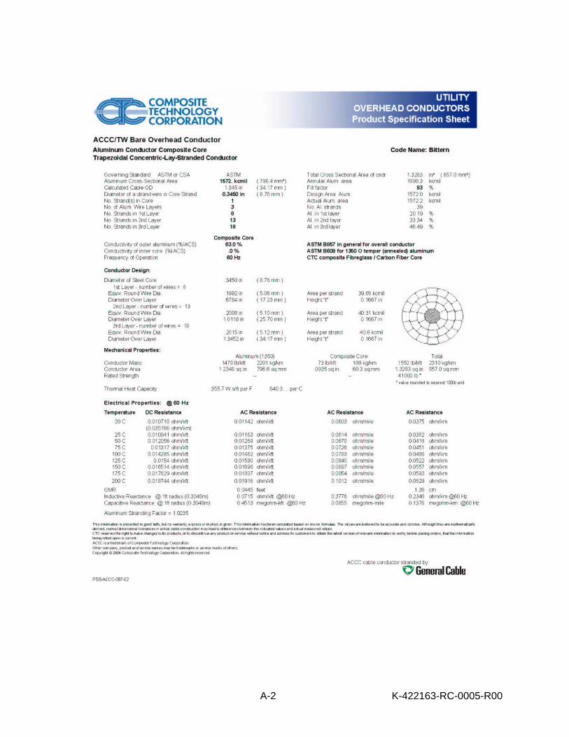
1.0 INTRODUCTION An Aeolian Vibration Test was performed on a sample of 1.345 inch (34.17 mm), 1572 kcmil, “Bittern” Aluminum Conductor, Composite Core/Trapezoidal Wire (ACCC/TW) conductor for Composite Technology Corporation (CTC). The conductor consists of a single composite glass and carbon fiber core covered by 3 layers of 39 annealed, trapezoidally-shaped aluminum alloy wires. The composite core is manufactured by CTC and the conductor is stranded by General Cable. The specifications for the conductor are shown in Appendix A. The test was performed between July 28, 2005 and September 14, 2005 by Kinectrics North America Inc. personnel at 800 Kipling Avenue, Toronto, Ontario, M8Z 6C4, Canada under CTC Purchase Order No. 00796. 2.0 TEST OBJECTIVE AND STANDARD The objective of the Aeolian Vibration Test is to assess the fatigue performance of the ACCC/TW conductor under typical aeolian vibrations.
PRIVATE INFORMATION Contents of this report shall not be disclosed without authority of the client.
Kinectrics North America Inc., 800 Kipling Avenue, Toronto, Ontario, M8Z 6C4
K-422163-RC-0005-R00
2
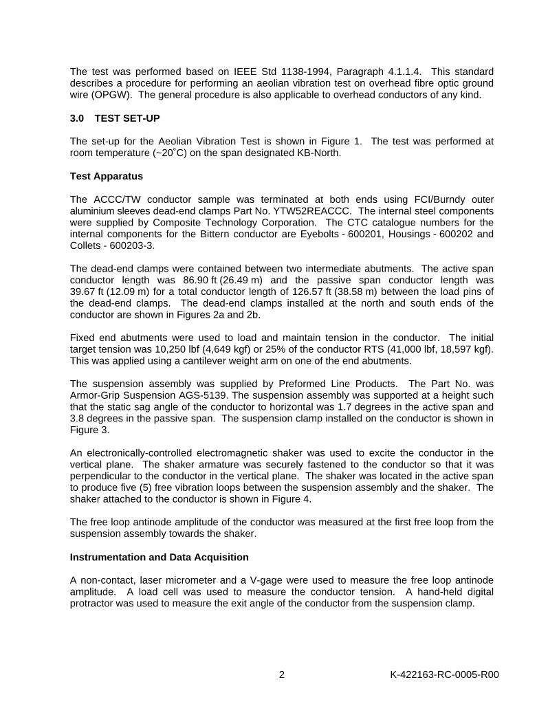
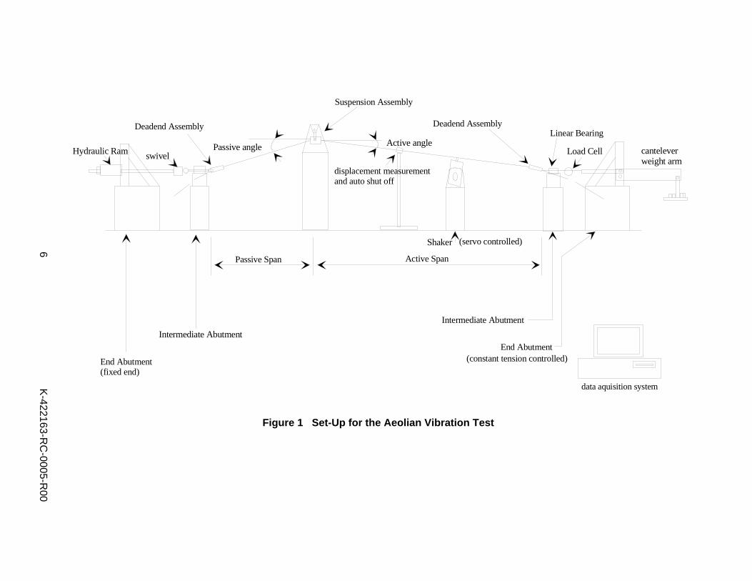
The test was performed based on IEEE Std 1138-1994, Paragraph 4.1.1.4. This standard describes a procedure for performing an aeolian vibration test on overhead fibre optic ground wire (OPGW). The general procedure is also applicable to overhead conductors of any kind. 3.0 TEST SET-UP The set-up for the Aeolian Vibration Test is shown in Figure 1. The test was performed at room temperature (~20˚C) on the span designated KB-North. Test Apparatus
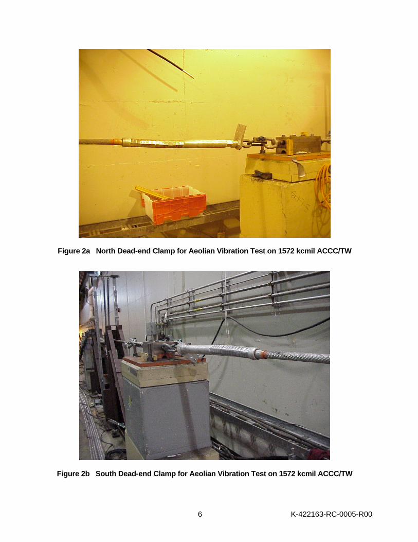
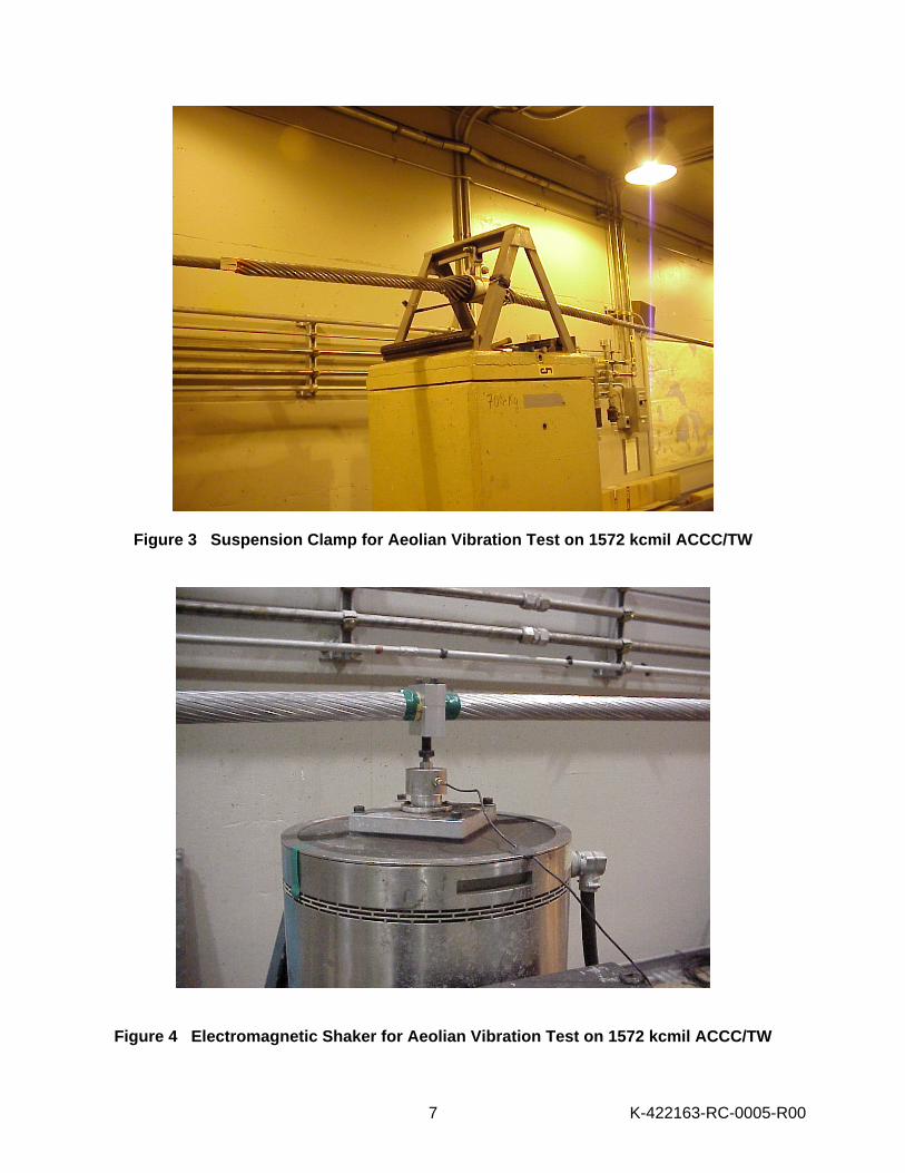
The ACCC/TW conductor sample was terminated at both ends using FCI/Burndy outer aluminium sleeves dead-end clamps Part No. YTW52REACCC. The internal steel components were supplied by Composite Technology Corporation. The CTC catalogue numbers for the internal components for the Bittern conductor are Eyebolts - 600201, Housings - 600202 and Collets - 600203-3. The dead-end clamps were contained between two intermediate abutments. The active span conductor length was 86.90 ft (26.49 m) and the passive span conductor length was 39.67 ft (12.09 m) for a total conductor length of 126.57 ft (38.58 m) between the load pins of the dead-end clamps. The dead-end clamps installed at the north and south ends of the conductor are shown in Figures 2a and 2b. Fixed end abutments were used to load and maintain tension in the conductor. The initial target tension was 10,250 lbf (4,649 kgf) or 25% of the conductor RTS (41,000 lbf, 18,597 kgf). This was applied using a cantilever weight arm on one of the end abutments. The suspension assembly was supplied by Preformed Line Products. The Part No. was Armor-Grip Suspension AGS-5139. The suspension assembly was supported at a height such that the static sag angle of the conductor to horizontal was 1.7 degrees in the active span and 3.8 degrees in the passive span. The suspension clamp installed on the conductor is shown in Figure 3. An electronically-controlled electromagnetic shaker was used to excite the conductor in the vertical plane. The shaker armature was securely fastened to the conductor so that it was perpendicular to the conductor in the vertical plane. The shaker was located in the active span to produce five (5) free vibration loops between the suspension assembly and the shaker. The shaker attached to the conductor is shown in Figure 4. The free loop antinode amplitude of the conductor was measured at the first free loop from the suspension assembly towards the shaker. Instrumentation and Data Acquisition A non-contact, laser micrometer and a V-gage were used to measure the free loop antinode amplitude. A load cell was used to measure the conductor tension. A hand-held digital protractor was used to measure the exit angle of the conductor from the suspension clamp.
K-422163-RC-0005-R00
3
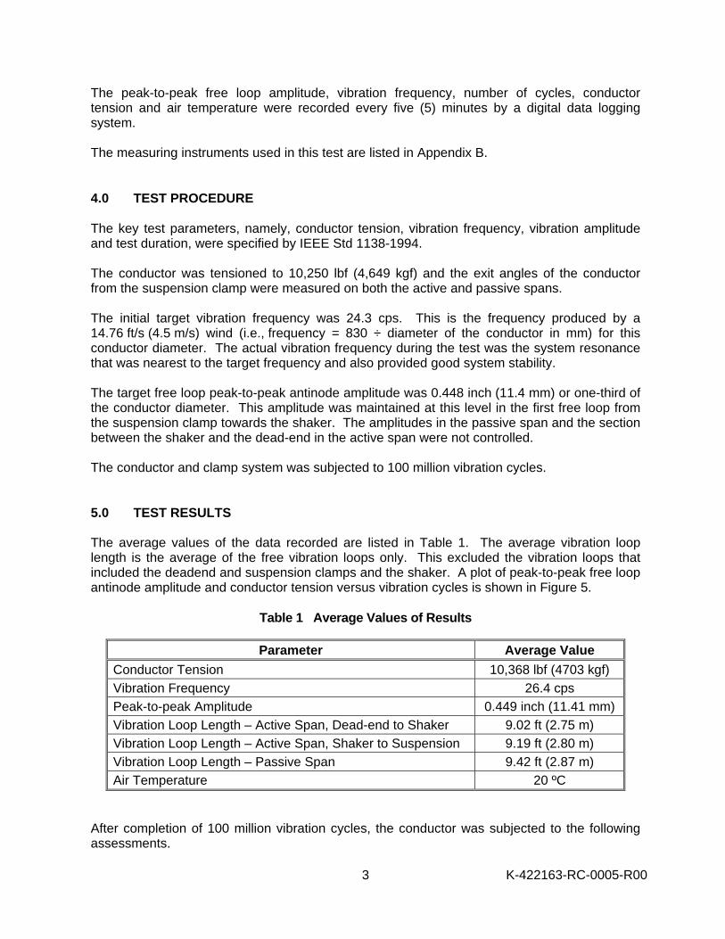
The peak-to-peak free loop amplitude, vibration frequency, number of cycles, conductor tension and air temperature were recorded every five (5) minutes by a digital data logging system. The measuring instruments used in this test are listed in Appendix B. 4.0 TEST PROCEDURE The key test parameters, namely, conductor tension, vibration frequency, vibration amplitude and test duration, were specified by IEEE Std 1138-1994. The conductor was tensioned to 10,250 lbf (4,649 kgf) and the exit angles of the conductor from the suspension clamp were measured on both the active and passive spans. The initial target vibration frequency was 24.3 cps. This is the frequency produced by a 14.76 ft/s (4.5 m/s) wind (i.e., frequency = 830 ÷ diameter of the conductor in mm) for this conductor diameter. The actual vibration frequency during the test was the system resonance that was nearest to the target frequency and also provided good system stability. The target free loop peak-to-peak antinode amplitude was 0.448 inch (11.4 mm) or one-third of the conductor diameter. This amplitude was maintained at this level in the first free loop from the suspension clamp towards the shaker. The amplitudes in the passive span and the section between the shaker and the dead-end in the active span were not controlled. The conductor and clamp system was subjected to 100 million vibration cycles. 5.0 TEST RESULTS The average values of the data recorded are listed in Table 1. The average vibration loop length is the average of the free vibration loops only. This excluded the vibration loops that included the deadend and suspension clamps and the shaker. A plot of peak-to-peak free loop antinode amplitude and conductor tension versus vibration cycles is shown in Figure 5.
Table 1 Average Values of Results
Parameter Average Value Conductor Tension 10,368 lbf (4703 kgf) Vibration Frequency 26.4 cps Peak-to-peak Amplitude 0.449 inch (11.41 mm) Vibration Loop Length – Active Span, Dead-end to Shaker 9.02 ft (2.75 m) Vibration Loop Length – Active Span, Shaker to Suspension 9.19 ft (2.80 m) Vibration Loop Length – Passive Span 9.42 ft (2.87 m) Air Temperature 20 ºC
After completion of 100 million vibration cycles, the conductor was subjected to the following assessments.
K-422163-RC-0005-R00
4
1) A 46 ft (14 m) and a 33 ft (10 m) conductor sample were cut out from the active and
passive dead-ends, respectively. The exposed (cut) ends were terminated using an epoxy-resin and steel block housing. Both samples were tension tested to determine the remaining pullout strength. Unfortunately, the active deadend sample failed prematurely in the epoxy housing during loading and therefore is invalid. The passive deadend failed at 39,068 lbf (17,721 kgf) or 95.3% of the RTS of the conductor. This meets the minimum strength requirement of 95% RTS for full tension clamps according to ANSI C119.4.
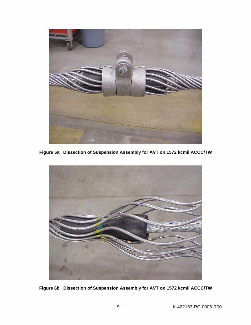
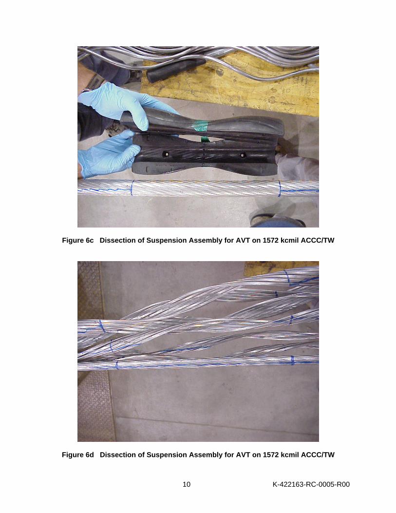
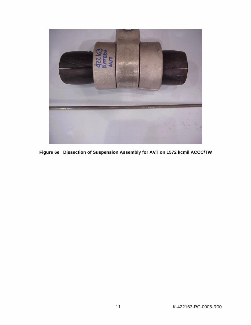
2) A 13 ft (4 m) conductor sample containing the suspension was cut. The suspension and
conductor were dissected and visually inspected for any damage to the suspension components, the aluminum wires, and/or core material. Photos of the dissected suspension assembly are shown in Figures 6a, b, c, d and e. There was no visual indication of any damage to the suspension components, any of the three aluminum (3) wire layers or the core material.
3) The remaining conductor from the free loops section of the active span was removed. The conductor was dissected and visually inspected for any damage to the aluminum wires, and/or core material.
There was no visual indication of any damage to the three aluminum (3) wire layers or the core material.
Prepared by M. Kastelein Technical Specialist Transmission and Distribution Technologies Business
M. Colbert Technical Specialist Transmission and Distribution Technologies Business
C.J. Pon Principal Engineer Transmission and Distribution Technologies Business
Approved by: Dr. J. Kuffel General Manager Transmission and Distribution Technologies Business

K-422163-RC-0005-R00
5
MJK:MC:CJP:JC
K-422163-RC-0005-R00
6
DISCLAIMER KNAI has taken reasonable steps to ensure that all work performed meets industry standards as set out in KNAI Quality Manual, and that, for the intended purpose of this report, is reasonably free of errors, inaccuracies or omissions. KNAI DOES NOT MAKE ANY WARRANTY OR REPRESENTATION WHATSOEVER, EXPRESS OR IMPLIED, WITH RESPECT TO THE MERCHANTABILITY OR FITNESS FOR ANY PARTICULAR PURPOSE OF ANY INFORMATION CONTAINED IN THIS REPORT OR THE RESPECTIVE WORKS OR SERVICES SUPPLIED OR PERFORMED BY KNAI. KNAI does not accept any liability for any damages, either directly, consequentially or otherwise resulting from the use of this report. © Kinectrics North America Inc., 2005
End AbutmentIntermediate Abutment
Intermediate Abutment
Shaker
Active SpanPassive Span
Deadend Assembly
Suspension Assembly
Deadend Assembly
displacement measurementand auto shut off
(servo controlled)
(constant tension controlled)End Abutment(fixed end)
Load Cell
data aquisition system
Linear Bearing
Hydraulic Ram swivelActive angle
canteleverweight arm
Passive angle
Figure 1 Set-Up for the Aeolian Vibration Test
6
K-422163-R
C-0005-R
00
6 K-422163-RC-0005-R00
Figure 2a North Dead-end Clamp for Aeolian Vibration Test on 1572 kcmil ACCC/TW
Figure 2b South Dead-end Clamp for Aeolian Vibration Test on 1572 kcmil ACCC/TW
7 K-422163-RC-0005-R00
Figure 3 Suspension Clamp for Aeolian Vibration Test on 1572 kcmil ACCC/TW
Figure 4 Electromagnetic Shaker for Aeolian Vibration Test on 1572 kcmil ACCC/TW
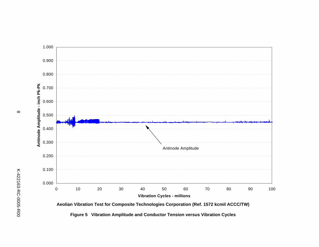
Aeolian Vibration Test for Composite Technologies Corporation (Ref. 1572 kcmil ACCC/TW)
Figure 5 Vibration Amplitude and Conductor Tension versus Vibration Cycles
0.000
0.100
0.200
0.300
0.400
0.500
0.600
0.700
0.800
0.900
1.000
0 10 20 30 40 50 60 70 80 90 100
Vibration Cycles - millions
Ant
inod
e A
mpl
itude
- in
ch P
k-Pk
Antinode Amplitude
8
K-422163-R
C-0005-R
00
9 K-422163-RC-0005-R00
Figure 6a Dissection of Suspension Assembly for AVT on 1572 kcmil ACCC/TW
Figure 6b Dissection of Suspension Assembly for AVT on 1572 kcmil ACCC/TW
10 K-422163-RC-0005-R00
Figure 6c Dissection of Suspension Assembly for AVT on 1572 kcmil ACCC/TW
Figure 6d Dissection of Suspension Assembly for AVT on 1572 kcmil ACCC/TW
11 K-422163-RC-0005-R00
Figure 6e Dissection of Suspension Assembly for AVT on 1572 kcmil ACCC/TW
A-1 K-422163-RC-0005-R00
APPENDIX A
DATA SHEET FOR COMPOSITE TECHNOLOGY CORPORATION “BITTERN” 1572 KCMIL ACCC/TW CONDUCTOR
A-2 K-422163-RC-0005-R00
ISO-9001 Form: QF11-1 Rev 0, 97-10
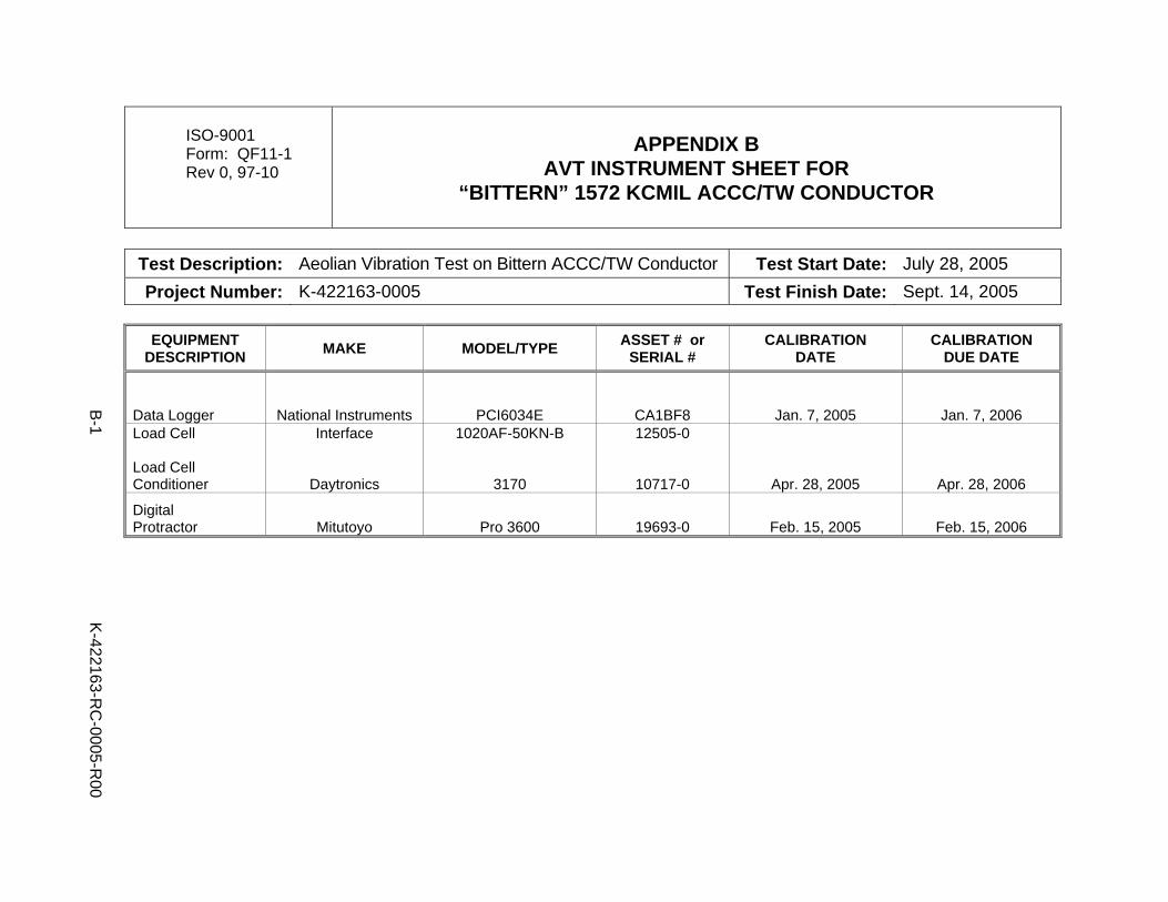
APPENDIX B
AVT INSTRUMENT SHEET FOR “BITTERN” 1572 KCMIL ACCC/TW CONDUCTOR
Test Description: Aeolian Vibration Test on Bittern ACCC/TW Conductor Test Start Date: July 28, 2005 Project Number: K-422163-0005 Test Finish Date: Sept. 14, 2005
EQUIPMENT
DESCRIPTION MAKE MODEL/TYPE ASSET # or SERIAL #
CALIBRATION DATE
CALIBRATION DUE DATE
Data Logger National Instruments PCI6034E CA1BF8 Jan. 7, 2005 Jan. 7, 2006 Load Cell Load Cell Conditioner
Interface
Daytronics
1020AF-50KN-B
3170
12505-0
10717-0 Apr. 28, 2005 Apr. 28, 2006
Digital Protractor Mitutoyo Pro 3600 19693-0 Feb. 15, 2005 Feb. 15, 2006
B-1
K
-422163-RC
-0005-R00