Embed Size (px)
Citation preview

IM-P358-24 CH Issue 3 1
AEL6 SeriesSmart Electric Linear Actuators for
DN15 to DN100 Control ValvesInstallation and Maintenance Instructions
1. Safety information
2. Global information
3. Installation
4. Commissioning
5. Maintenance and spare parts
IM-P358-24CH Issue 3
3580450/3
© Copyright 2014
Printed in France
IM-P358-24 CH Issue 32
1. Safety informationSafe operation of this product can only be guaranteed if it is properly installed, commissioned, used and maintained by qualified personnel (see Section 1.13) in compliance with the operating instructions. General installation and safety instructions for pipeline and plant construction, as well as the proper use of tools and safety equipment must also be complied with.
See separate Installation and Maintenance Instructions for the control valve.
If the actuator is handled improperly or not used as specified, the resultant may:
- cause danger of the life and limb of the third party, - damage the actuator and other assets belonging to the owner, - hinder the performance of the actuator.
1.1 Wiring notesEvery effort has been made during the design of the actuator to ensure the safety of the user, but the following precautions must be followed:
i) Maintenance personnel must be suitably qualified in working with equipment containing hazardous live voltages.
ii) Ensure correct installation. Safety may be compromised if the installation of the product is not carried out as specified in this manual.
iii) Isolate the actuator from the mains supply before opening the unit.
iv) The actuator is designed as an installation category II product, and is reliant on the building installation for overcurrent protection and primary isolation.
v) Wiring should be carried out in accordance with IEC 60364 or equivalent.
vi) Fuses should not be fitted in the protective earth conductor. The integrity of the installation protective earth system must not be compromised by the disconnection or removal of other equipment.
vii) A disconnecting device (switch or circuit breaker) must be included in the building installation. This must be in close proximity to the equipment and within easy reach of the operator.
- There must be a 3 mm contact separation in all poles.
- It must be marked as the disconnecting device for the actuator.
- It must not interrupt the protective earth conductor.
- It must not be incorporated into a mains supply cord.
- The requirements for the disconnecting device are specified in IEC 60947-1 and IEC 60947-3 or equivalent.
viii) The actuator must not be located in such a way that the disconnecting device is made difficult to operate.

IM-P358-24 CH Issue 3 3
1.2 Safety requirements and electromagnetic compatibility
The product may be exposed to interference above the limits of industrial immunity if:
- The product or its wiring is located near to a radio transmitter.
- Excessive electrical noise occurs on the mains supply.
- Cellular telephones and mobile radios may cause interference if used within approximately one metre of the product or its wiring. The actual separation necessary will vary according to the power of the transmitter.
- Power line protectors (ac) should be installed if mains supply noise is likely.
- Protectors can combine filtering, suppression, surge and spike arrestors.
For a copy of the declaration of conformity contact Spirax Sarco.
1.3 Intended useReferring to the Installation and Maintenance Instructions, name-plate and Technical Information Sheet, check that the product is suitable for the intended use / application.
i) Check material suitability, pressure and temperature and their maximum and minimum values. If the maximum operating limits of the product are lower than those of the system in which it is being fitted, or if malfunction of the product could result in a dangerous overpressure or overtemperature occurrence, ensure
a safety device is included in the system to prevent such over-limit situations.
ii) Determine the correct installation situation.
iii) Spirax Sarco products are not intended to withstand external stresses that may be induced by any system to which they are fitted. It is the responsibility of the installer to consider these stresses and take adequate precautions to minimise them.
This product is CE marked. It complies with the requirements of 73 / 23 / EEC as amended by 93 / 68 / EEC on the harmonisation of the law of Member States relating to electrical equipment designed for use within certain voltage limits (LVD), by meeting the standard for safety of electrical equipment for measurement control and laboratory use.
This product complies with the requirement of 89 / 336 / EEC as amended by 92 / 31 / EEC and 93 / 68 / EEC on the approximation of laws of the Member States relating to Electromagnetic Compatibility, by meeting the generic standard of emissions for an industrial environment and the generic standard of immunity for an industrial environment.

IM-P358-24 CH Issue 34
1.4 AccessEnsure safe access and if necessary a safe working platform (suitably guarded)before attempting to work on the product. Arrange suitable lifting gear if required.
1.5 LightingEnsure adequate lighting, particularly where detailed or intricate work is required.
1.6 Hazardous liquids or gases in the pipelineConsider what is in the pipeline or what may have been in the pipeline at some previous time. Consider: flammable materials, substances hazardous to health, extremes of temperature.
1.7 Hazardous environment around the productConsider: explosion risk areas, lack of oxygen (e.g. tanks, pits), dangerous gases, extremes of temperature, hot surfaces, fire hazard (e.g. during welding), excessive noise, moving machinery.
1.8 The systemConsider the effect on the complete system of the work proposed. Will anyproposed action (e.g. closing isolation valves, electrical isolation) put any otherpart of the system or any personnel at risk? Dangers might include isolation of vents or protective devices or the rendering ineffective of controls or alarms. Ensure isolation valves are turned on and off in a gradual way to avoid system shocks.
1.9 Pressure systems Ensure that any pressure is isolated and safely vented to atmospheric pressure. Consider double isolation (double block and bleed) and the locking or labelling of closed valves. Do not assume that the system has depressurised even when the pressure gauge indicates zero.
1.10 TemperatureAllow time for temperature to normalise after isolation to avoid danger of burns.
1.11 Tools and consumablesBefore starting work ensure that you have suitable tools and / or consumables available. Use only genuine Spirax Sarco replacement parts.
1.12 Protective clothingConsider whether you and/or others in the vicinity require any protective clothing to protect against the hazards of, for example, chemicals, high / low temperature, radiation, noise, falling objects, and dangers to eyes and face.

IM-P358-24 CH Issue 3 5
1.13 Permits to workAll work must be carried out or be supervised by a suitably competent person.Installation and operating personnel should be trained in the correct use of the product according to the Installation and Maintenance Instructions.
Where a formal 'permit to work' system is in force it must be complied with. Where there is no such system, it is recommended that a responsible person should know what work is going on and, where necessary, arrange to have an assistant whose primary responsibility is safety.
Post 'warning notices' if necessary.
1.14 HandlingManual handling of large and/or heavy products may present a risk of injury. Lifting, pushing, pulling, carrying or supporting a load by bodily force can cause injury particularly to the back. You are advised to assess the risks taking into account the task, the individual, the load and the working environment and use the appropriate handling method depending on the circumstances of the work being done.
1.15 Residual hazardsIn normal use the external surface of the product may be very hot. If used at the maximum permitted operating conditions the surface temperature of some products may reach temperatures of 90°C (194°F).
Many products are not self-draining. Take due care when dismantling or removing the product from an installation (refer to 'Maintenance instructions').
1.16 FreezingProvision must be made to protect products which are not self-draining against frost damage in environments where they may be exposed to temperatures below freezing point.
1.17 DisposalUnless otherwise stated in the Installation and Maintenance Instructions, this product is recyclable and no ecological hazard is anticipated with its disposal providing due care is taken.
1.18 Returning productsCustomers and stockists are reminded that under EC Health, Safety and Environment Law, when returning products to Spirax Sarco they must provide information on any hazards and the precautions to be taken due to contamination residues or mechanical damage which may present a health, safety or environmental risk. This information must be provided in writing including Health and Safety data sheets relating to any substances identified as hazardous or potentially hazardous.

IM-P358-24 CH Issue 36
2. General information2.1 UseAEL6 series electric linear actuators are for use with LE and KE two-port control valves,QL three-port valves and all bellows sealed options. Actuators will normally be supplied fitted to the control valve. When supplied separately, ensure the actuator selected is capable of giving the force necessary to close the two-port or three-port control valve against the expected differential pressure. See the appropriate product specific Technical Information Sheet for full details of the control valve.AEL6 series actuators are available for VMD (Valve motor drive) input, 4 - 20 mA or 2 - 10 Vdcinputs (when an electronic positioner is fitted). 230 Vac, 115 Vac, and 24 Vac options are available. Full details of the actuator types, and reference numbers, are given in Table 1.
Table 1 Series in the range AEL6000Product A = Actuator A
Type E = Electric E
Movement L = Linear L
Series 6 6
Thrust (kN)
2 = 2.3
2
3 = 4.5
4 = 8
5 = 14
6 = 25
Stroke (mm)2 = 50
23 = 65 (AEL65 only), 95 / 100 (AEL66 only)
Maximum speed (mm/s)
1 = 0 - 1.0 (AEL62_, AEL63_, AEL64 and AEL66_ series only)
12 = 1.1 - 2.0 (AEL64_ and AEL65_ series only)
3 = 2.1 - 4.5 (AEL63_ series only)
Supply voltage
1 = 230 Vac
12 = 115 Vac
3 = 24 Vac and 24 Vdc
Control signal
F = 24 V VMD, 0 / 2-10 Vdc and 0 / 4-20 mA (supply voltage 3 only)
J
G = 115 V VMD, 0 / 2-10 Vdc and 0 / 4-20 mA (supply voltage 2 only)
H = 24 V VMD, 0 / 2-10 Vdc and 0 / 4-20 mA (supply voltage 2 only)
J = 230 V VMD, 0 / 2-10 Vdc and 0 / 4-20 mA (supply voltage 1 only)
K = 24 V VMD, 0 / 2-10 Vdc and 0 / 4-20 mA (supply voltage 1 only)
Failure mode
X = No mechanical/electrical fail safe deviceS
S = Super capacitor fail safe (non retrofittable)
Selection example: A E L 6 2 2 1 1 J S
Selection example: A 230 Vac fail safe electric actuator to suit a 25 mm control valve with PTFE stem seals, to have class IV shut-off against 10 bar differential pressure. There is no requirement for high actuating speed, the control signal is 230 V VMD.

IM-P358-24 CH Issue 3 7
2.2 Operation The motor rotation is transmitted through low wear and low backlash spur gears to provide linear movement of the actuator spindle. An anti-rotation plate is fitted to prevent rotation of the spindle during operation. The stop positions (Top and bottom) are controlled by an Electronic processor. They can define by measure of its force (torque mode) or by its position (position mode).The actuator is fitted to the valve stem. When the one or the two stop position is defined as the torque mode, it is possible to see this force thank the disc springs.
2.3 Manual operation The handwheel is used to operate the actuator if the power supply has failed or during installation work such as mounting onto a valve or setting the limit positions.• The handwheel is permanently engaged and turns during motor operation for all the models,
with the exception of the AEL6631_.• The AEL6631_ actuator has handwheel which must be engaged for manual operation.
The button on the cover has to be depressed to engage the handwheel
Do not exceed the set stroke limits when operating manually.Do not operate the handwheel using excessive force.Do not try to block the handwheel when the actuator is operating.Failure to observe this warning may result in damage to the actuator.

IM-P358-24 CH Issue 38
Note: Please read Section 1, 'Safety information' before proceeding with installation.
3.1 Location The actuator should be mounted above the valve with sufficient space to remove the cover and general ease of access. When selecting the location, make sure that the actuator is not exposed to an ambient temperature exceeding the range -20°C to +60°C . If necessary, provide insulation to prevent overheating.The actuator is rated at IP65, but only when the lid is correctly fitted (see Section 3.3). It is recommended that adequate shelter is provided for outdoor installations.If condensation is present a heating resistor should be installed. Refer to technical information Sheets for details.The operating modes for these electric actuators are for S2 – short and S4 – intermittent service as stated in IEC 6034-1, 8.
3.2 Connecting the actuator to the valveNormally the AEL6 actuator will be supplied already fitted to the valve. However, should it be necessary to fit an actuator, the following procedure should be adopted:
When mounting an actuator on a valve, never drive the actuator electrically, instead use the handwheel.
Note: When mounting the actuator to the valve it is advised that the polystyrene packaging remains on the head of the actuator. The actuator can become damaged if it dropped or if it topples down onto a hard surface without the packaging.
3.2.1 AEL62_ and AEL63_ and AEL64_ and AEL65 actuator 1. If the diameter of the valve is smaller than DN65 the AEL6911 adaptor must be used for the Spira-trolTM K valve or the AEL6911 J adaptor for the Spira-trolTM J valve. The mounting flange is: EL5970 for the DN15 - DN50 Spira-trolTM K valve or EL5971 for the DN65 - DN100 Spira-trolTM K valve or AEL5971J for the DN15 - DN100 Spira-trolTM J valve.
2. Remove the actuator retaining nut from the valve and place the mounting flange over the valve bonnet thread.
3. Refit the actuator retaining nut and tighten as follows: 50 Nm for the M34 or 100 Nm for the M50.
4. Remove the actuator pillar nuts (3) using the handwheel to retract the actuator spindle.
5. Untighten the four screws (6) until the nut comes free (about 2 turns for each screw).
6. Screw the valve stem lock-nut (4) onto the valve stem as follows: - 12 mm maximum for M8 thread (DN15 to DN50) - 16 mm maximum for M12 thread (DN65 to DN100).
7. Put the actuator onto the mounting flange.
8. Refit and tighten the pillar nuts (3) to a torque of 100 Nm.
9. Using the handwheel lower the actuator stem until it touches the valve stem connection.
10. Lift the valve stem up into the actuator stem until it comes to a stop. It is important that this operation is not carried out with the valve plug on it's seat after
tightening the retaining nut by hand. One marking ring should be exposed 1 mm below the bottom of the retaining nut, as shown in Figure 2.
11. Screw the 4 items (6), the lock-nut (5).
3. Installation

IM-P358-24 CH Issue 3 9
Fig. 2
It is important that this operation is not carried out with the valve plug on its seat after tightening the retaining nut by hand.
4
31
2
5
6
Fig. 1
Before the pillar nuts are tightened, make sure that the pillar ends are completely inserted into the bores of the valve mounting flange.If necessary, correct the position of the actuator using the handwheel.
6
24
25Marking ring

IM-P358-24 CH Issue 310
When mounting an actuator on a valve, never drive the actuator electrically, instead use the handwheel.
1. When coupling the actuator to the valve a mounting flange (12) type EL5972 or type EL5973 is required.
2. Remove the actuator retaining nut (15) from the valve and place the mounting flange over the valve bonnet thread.
3. Refit the actuator retaining nut (15) and tighten.
4. Remove the actuator pillar nuts (13). Using the handwheel retract the actuator spindle.
5. Screw the valve stem lock-nut (14) 2 x valve stem diameters onto the valve stem.
6. Lower the actuator onto the valve so that the pillar shoulders sit squarely against the mounting flange.
7. Refit and tighten the pillar nuts (13).
3.2.2 AEL66_ actuator connection to valve
Important: Disc springs must be assembled correctly.
There are 2 sets of 3 disc springs, which must be assembled in the correct order. The convex side of a spring must be assembled to the convex side of the next spring. Conversely, the concave side of the spring must be assembled to the concave side of the next spring.Insert the first set of springs (9, see Figure 5) inside the actuator adaptor mounting. Next push the valve adaptor (10) inside the actuator mounting so that the springs are pushed up to the top. Push the second set of disc springs (9) over the adaptor nut (11) into the actuator by hand. The nut should be screwed in until the adaptor is held firmly inside the actuator, but not too tight such that the adaptor cannot be rotated.
Fig. 3 Assembling the disc springs Fig. 4 Correct assembly of the valve adaptor for the EL565_ actuator

IM-P358-24 CH Issue 3 11
Fig. 5
1014151213
11
8. Lift the valve stem up into the actuator connecting piece (10), until it stops.
9. Screw the valve adaptor (10) onto the valve stem until it meets the lock-nut or comes to a stop (whichever is first).
10. Screw the retaining nut (11) into the actuator spindle until the returning unit is level with the housing.
Use the peg spanner (found tied to the pillar) to tighten the retaining nut (11).
It is important that when the retaining nut is screwed hand tight, the valve plug must not be on its seat. Ensure that one marking ring is exposed 1 mm below the bottom of the retaining nut.
Before the pillar nuts are tightened, make sure that the pillar ends are completely inserted into the bores of the mounting flange. If necessary, correct the position of the actuator using the handwheel.
9
10
9
11
Fig. 6

IM-P358-24 CH Issue 312
3.3 Removing and fitting the actuator cover
3.3.1 AEL62_, AEL63_, AEL 64_ and AEL65_actuatorsRemove the handwheel by loosening the socket headed grub screw (4 mm A/F allen key).Hold both of the actuator pillars at the top. Using your thumbs gently ease the lid off.
Note: When replacing the cover ensure that the two longest locating guides on the interior of the cover are aligned with the two recesses on the actuator housing. Firmly press down the actuator housing ensuring the 'o' ring on the actuator is completely concealed.
3.3.2 AEL66_ actuatorsFor the AEL66_actuator remove the handwheel first by loosening the grub screw. Unscrew the 3 fixing screws around the bottom edge of the lid, then gently lift the lid off.
To fit the lid ensures that it is orientated correctly. Push the cover over the handwheel shift on the AEL66_.
Align the 3fixing screws over the tapped holes in the gearbox housing. Tighten the fixing screws with a suitable screwdriver.
AEL66_actuator.After the lid is fitted ensure the handwheel button can be pushed down to engage the handwheel.
Remove the cover byloosening the 4 x screws.
Fig. 7

IM-P358-24 CH Issue 3 13
3.4 Fitting the additional limit switches Should it be necessary to fit any accessories, the following procedure should be adopted. AEL6951 Auxiliary switches (Normally closed:NC)
Options AEL6952 Auxiliary switches (Normally opened:NO) AEL6953 Anti-condensate heater 24 V AEL6954 Anti-condensate heater 110-230 V
3.4.1 Fitting the additional limit switchesAll actuators can be provided with additional limit switches (Figure 11, page 14). Mounting locations are on the limit switch, angle bracket AEL62_, AEL63_, AEL64_ and AEL65_ : Remove the handwheel by loosening the socket headed grub screw (4 mm A/F Allen key).
Note: When replacing the cover ensure that the two longest locating guides on the interior of the cover are aligned with the two recesses on the actuator housing. Firmly press down the actuator housing ensuring the 'O' ring on the actuator is completely concealed.For the AEL66_ unscrew the 3 fixing screws around the bottom edge of the lid, then gently lift the lid off.To fit the lid ensure that it is orientated correctly. Push the cover over the handwheel shift on the AEL66_. Align the 3 fixing screws over the tapped holes in the gearbox housing. Tighten the fixing screws with a suitable screwdriver.
Fig. 8
Fig. 9Hold both of the actuator
pillars at the top. Using your thumbs gently ease the lid
off.Fig. 10

IM-P358-24 CH Issue 314
Section 3.5.6 shows how the switches are wired to the terminals. Fit the extend switch and the retract switch position (1) and (2) respectively in Figure 11.
Insert the auxiliary limit switches by a simple snap-in connection. Refit the switching plate and tighten the screws. Their cables are connected directly into the terminals on the main board.
Note: When removing the auxiliary limit switches carefully lever the limit switch housing using a screwdriver and remove the switch.
Refer to Section 3.5.9 in order to fit the additional terminal blocks for the auxiliary limit switches.
To fit limit switches remove the screws holding the switching plate and carefully remove.The cams are fitted to the switching plate, with infinitely variable adjustment. The direction of travel of the cam is from the lever pivot point towards the roller.
AEL66_ actuator.After the lid is fitted ensure the handwheel button can be pushed down to engage the hanwheel
Fig. 11
18 19 20 21
1
2
X12 = Switch for the closed position of the valve (1)
X13 = Switch for the open position of the valve (2)
X13
X12

IM-P358-24 CH Issue 3 15
3.4.2 Fitting the anti-condense heaterThe location of the fixing holes to fit the anti-condense heater is as shown in Figure 12.
Refer to Section 3.5.9 in order to fit the additional blocks for the anti-condense heater(ref. AEL6953 for 24 V and AEL6954 for 115 / 230 V) with its cable which will be connected directly into terminals on the main board (connector x101).
Fig. 12
Connecting cable (X101)
IM-P358-24 CH Issue 316
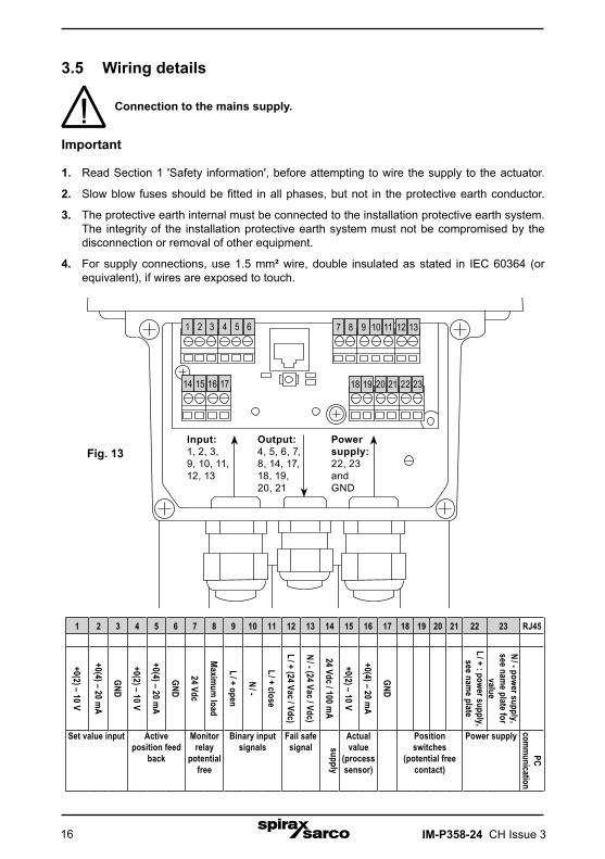
3.5 Wiring details
Connection to the mains supply.
Important
1. Read Section 1 'Safety information', before attempting to wire the supply to the actuator.
2. Slow blow fuses should be fitted in all phases, but not in the protective earth conductor.
3. The protective earth internal must be connected to the installation protective earth system. The integrity of the installation protective earth system must not be compromised by the disconnection or removal of other equipment.
4. For supply connections, use 1.5 mm² wire, double insulated as stated in IEC 60364 (or equivalent), if wires are exposed to touch.
RJ45
PC com
munication
23
N / - power supply, see nam
e plate for value
Power supply
22
L / + : power supply, see nam
e plate
21
Position switches
(potential free contact)
20191817
GND
16
+0(4) – 20 mA
Actual value
(process sensor)
15
+0(2) – 10 V
14
24 Vdc / 100 mA
supply
13
N / - (24 Vac / Vdc)
Fail safe signal
12
L / + (24 Vac / Vdc)
11
L / + close
Binary input signals
10
N / -
9
L / + open
8
Maxim
um load
Monitor relay
potential free
7
24 Vdc
6
GND
Active position feed
back
5
+0(4) – 20 mA
4
+0(2) – 10 V
3
GND
Set value input
2
+0(4) – 20 mA
1
+0(2) – 10 V
Output: 4, 5, 6, 7, 8, 14, 17, 18, 19, 20, 21
Power supply: 22, 23 and GND
232221201918
1312111087 9
17161514
21 3 54 6
Fig. 13Input:1, 2, 3, 9, 10, 11, 12, 13

IM-P358-24 CH Issue 3 17
3.5.1 Valve motor drive models
Standard voltage for this input is 24 V. 115 / 230 V are optional. This option (ref. AEL6972) is not retrofitable and should be addressed with the order.
The actuator is driven in 3 point service:- 9 = Opening (extend spindle).- 10 = Neutral.- 11 = Closing (retract spindle).
3.5.2 Set value
To drive the actuator with a 0 to 10 V or a4 - 20 mA input signal, the plugging is:- 1 = 0 - 10 V- 2 = 0 / 4 - 20 mA- 3 = GND
3.5.3 Active position feedback
The AEL6 actuator could send as output an active position feedback, especially if a cut-off by position is requested.- 4 = 0 - 10 V- 5 = 0 / 4 - 20 mA- 6 = GND
9 10 11
1 2 3
4 5 6

IM-P358-24 CH Issue 318
3.5.4 Fail safe (option)
The AEL6 actuator could be fitted with a power safe fail package (ref. AEL6974 and AEL6975) which will power the actuator with a 24 V signal to ensure a safety position.- 12 = L / +- 13 = N / -This option is not retrofitable and should be addressed with the order.
12 13
Fig. 14Internal super capacitor for thefollowing actuators:AEL62_, AEL63_, and AEL64_
Fig. 15External super capacitor for the following actuators:AEL65_ and AEL66_

IM-P358-24 CH Issue 3 19
3.5.5 Sensor feedback (option)
The AEL6 actuator could receive as an input an active process sensor feedback to the process controller.- 15 = 0 - 10 V- 16 = 0 / 4 - 20 mA- 17 = GND
3.5.6 Additional position switches (option)
The activation points of the optionally available posit ion switches are freely adjustable via cams. Plugging 18 / 19 and 20 / 21 provide potential free opening or closing contacts. The standard switches are rated to 230 Vac / 5 A.If ordering switches it is necessary to specify either:- Normally closed AEL6951 or- Normally open AEL6952.Special switches with gold plated contacts are available for low power (up to 100 mA and 30 V).
3.5.7 Voltage supply to process sensor (option)
The AEL6 actuator could provide a 24 Vdc at maximum at 100 mA unregulated output voltage to an external process sensor.- 14 = 24 Vdc / 100 mA- 17 = GND
15 16 17
18 19 20 21
14 17

IM-P358-24 CH Issue 320
3.5.8 Fault indicating relay (option)
As an option, plugins 7 and 8 allows to display parameterisable fault indication to a control room. It is based on normally open contact relay. This option (ref. AEL6973) is linked with the communication software.Load 100 mA maximum at 24 Vdc.This option is not retrofitable and should be addressed with the order.
7 8

IM-P358-24 CH Issue 3 21
3.5.9 Fitting additional terminal blocks for the following:
• Auxiliary limit switches• Anti-condense heater Ensure the mains power to the positioner or the VMD control signal is isolated
Where cams are fitted you will have to disconnect the metallic plate before you can connect the auxiliary switches.You have to clip the micro switches onto the main frame and then re-fit the metallic plate. Connect the wires as follows:- Switch 1 (Position 1) the closed position = X12 - Switch 2 (Position 2) the open position = X13When you have done the above you can adjust the position of the cam - Undo the metal screw (on the plastic cam), and use the plastic screw to change its position, when you reach the optimum position, retighten the metal screw.
Fig. 16
18 19 20 21
1
2
X12 = Switch for the closed position of the valve (1)
X13 = Switch for the open position of the valve (2)
X13
X12

IM-P358-24 CH Issue 322
For mounting the anti-condensate heater you have to fit with 2 screws and you mustconnect in the X101 connector.
3.5.10 The switches are shown in the normally closed condition i;e when the switchesare not engaged with the cams.Example: If the retract switch is engaged, terminals 1 and 2 will be shorted together.
Fig. 17
Connecting cable (X101)
IM-P358-24 CH Issue 3 23
4. CommissioningActuators supplied already fitted to control valves would be supplied already commissioned.However, should it be necessary to commission an actuator, the following procedure should be adopted.After installation or maintenance, ensure that the system is fully operational. Make a test alarms or protective devices.
4.1 Preliminary checks - All actuators1. Check that the actuator voltage corresponds to that required.
2. Ensure the wiring corresponds to that outlined in Section 3.5.
Ensure the assembly of the valve and actuator has been carried out according to the instructions in Section 3.2.
4.2 Automatic commissioning: 2-port and 3-port valves 1. It is possible to do the commissioning in an automatic way. Cut-offs have to be set
'by force / torque' for the linear valves or 'by position automatically' for the butterfly valves see the 'Software Installation Instructions' IM-P358-27 that have been supplied with the product. During automatic commissioning the actuator goes through the full programmed valve stroke automatically. Parameters specific to the valve are being measured and values are calculated and stored permanently in the actuator. Set value and position feedback range are scaled.
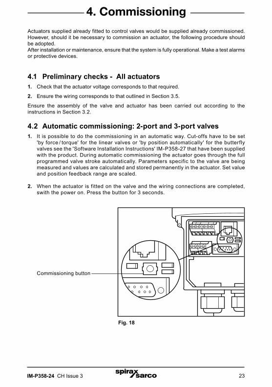
2. When the actuator is fitted on the valve and the wiring connections are completed, swith the power on. Press the button for 3 seconds.
Commissioning button
Fig. 18
IM-P358-24 CH Issue 324
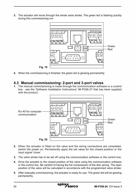
3. The actuator will move through the whole valve stroke. The green led is flashing quickly during this commissioning run.
4. When the commissioning is finished, the green led is glowing permanently.
4.3 Manual commissioning: 2-port and 3-port valves1. The manual commissioning is made through the communication software or a control
box - see the 'Software Installation Instructions' IM-P358-27 that has been supplied with the product.
2. When the actuator is fitted on the valve and the wiring connections are completed, switch the power on. Permanently apply the set value for the closed position or the input signal 'close'.
3. The valve stroke has to be set off using the communication software or the control box.
4. Drive the actuator to the closed position of the valve using the communication software or the control box. Be carefull of having the full compression of the disc spring. The open position of the valve will be calculated in accordance with the programmed valve stroke.
5. After manually commissioning, the actuator is ready for use. The green led will be glowing permanently.
GreenRed
GreenRed
RJ-45 for computer communication
Fig. 19
Fig. 20
IM-P358-24 CH Issue 3 25
Note: Before actioning any maintenance read the 'Safety information' in Section 1.
Always make sure that the electrical supply is switched off when carryingout any maintenance on the actuator or valve.
The AEL6 series actuators have a design life of approximately 200 000 full strokes or alternatively 1.5 million starts (1 start is 1 movement of the spindle). The maintenance required for the AEL6 series range of actuators is to inspect the condition inside of the spindle nut and to lubricate it. If that actuator has been operating beyond its design limits the spindle nut may require replacing.Do not use any coarse or abrasive materials or cleaning agent to clean the actuator.Only use a dry soft cloth.
Spare partsMaintenance spare kits are available for the range of AEL6 series actuators. The kits contain replacement spindle nuts, 'O' rings, the correct lubricating grease, plus full instructions to carry out the inspection, lubrication / spindle nut replacement. For more information contact your local Spirax Sarco branch or distributor.
5. Maintenance and spare parts

IM-P358-24 CH Issue 326

IM-P358-24 CH Issue 3 27

IM-P358-24 CH Issue 328