Embed Size (px)
Citation preview
Electrical Narrative - AEI Team 2 || 2015
AEI STUDENT DESIGN COMPETITION Electrical Report
2-11-2015

Electrical Narrative - AEI Team 09-2015
i
Table of Contents
Narrative Supporting Documentation
EXECUTIVE SUMMARY ii References A
1.0 PROJECT INTRODUCTION 1 Plant Matrix B
2.0 PROJECT GOALS 1 Greenhouse Transformation C
3.0 INTEGRATION 1 Glazing Study D
4.0 DAYLIGHTING 1 Grow Lighting E
5.0 GREENHOUSE DESIGN 3 Greenhouse Shades F
6.0 ENERGY 8 Greenhouse Optimization G
7.0 POWER DISTRIBUTION 9 Energy Use H
8.0 LIGHTING DESIGN 11 Overcurrent Protection Coordination I
9.0 SMART BUILDING DESIGN 13 Lighting Power Density J
10.0 DESIGN ADAPTABLITY 14 Lighting K
11.0 CONCLUSION 15 Market L
Control Narrative M
Network Diagram N
Levels of SMART building O
Drawings
Schedules E101
Basement & Level 1 Electrical Plan E102
Level 2 & 3 Electrical Plan E103
Level 4 & 5 Electrical Plan E104
Basement & Level 1 Lighting Plan E105
Level 2 & 3 Lighting Plan E106
Level 4 & 5 Lighting Plan E107
Panelboard Schedules E108
Building Riser Diagrams E109
Greenhouse Module E110

Electrical Narrative - AEI Team 09-2015
ii
Executive Summary Growing Power, Inc. is a nonprofit urban farming organization
located in Milwaukee, WI. The Synthesis team has been asked
to design a new Vertical Farm to help establish Growing
Power as a local and national resource for sustainable
agriculture. The farm will be located on the site of Growing
Power’s headquarters at 5500 Silver Spring Drive, Milwaukee,
WI.
The following sections describe the Synthesis
lighting/electrical team’s goals and overall design.
Supplemental material and drawings are included in the
appendices of this report.
Lighting/Electrical Goals:
Promote an educational environment for Growing
Power.
Consider the internal and external impact the
electrical system will have on other systems,
occupants, and surrounding communities.
Easily adapt to new building conditions, technological
advancements, and geographical regions.
Daylight The Synthesis lighting and electrical team minimized east west
exposure to maximize useful daylight in interior spaces.
Architectural programming was coordinated to locate rooms
with no outside exposure to now have views into the
greenhouses and outside. Low angle sun in winter will preheat
interior spaces helping to cut down on mechanical loads. In
the afternoon, east facing rooms will not receive daylight and
will save energy due to daylight harvesting methods.
Module Greenhouse Design The Vertical Farm consists of four tiers of greenhouses facing
south on the front of the building. The greenhouses have
been designed as module components, comprising of six
modules per greenhouse. A detailed glazing study was
completed in order to understand how different materials
transmit different spectrums of light specific to plant growth.
Specific design criteria was set fourth pertaining to the exact
crops Growing Power will be producing in each greenhouse in
a plant matrix. The team designed a supplemental grow
lighting configuration to provide a specific intensity and
spectrum of light to meet the growing requirements. A shade
with light transmission and thermal properties was selected
specific to each design set point. Scenarios were run in a
daylight model to determine the performance of each
greenhouse design. Together, the optimized glazing,
supplemental grow lights, and shade system create an ideal
plant growing environment for a variety of crop types year
round.
Energy and Power Growing Power will produce energy on site in the form of food
waste converted to biogas. This conversion occurs in an
outdoor anaerobic digester, located west of the building. This
biogas will be used to power a 200 kW microturbine,
producing quad-generation.
Quad-Generation – There will be four total outcomes from
the microturbine that will be used on site:
Electricity
Heating
Cooling
Carbon Dioxide
Electricity is a direct result of the microturbine, as well as heat
from the flue gas. However, the steam generated by the flue
gas will be used to run through an absorption chiller and
create a chilled water loop for building cooling. Excess carbon
dioxide will be filtered from the flue gas and sent into the
closed greenhouse modules. The supplemental carbon dioxide
is proven to increase plant growth of more than 40%. The
microturbine is responsible for being the prime mover for the
entire quad-generation scheme.
Lighting The building uses extremely efficient lighting. With an overall
building Lighting Power Density of 0.39 W/sf, the lighting
design power considerations beat the strictest energy codes in
the country, including Title 24 by more than 15%. Therefore
the building can adapt to any location in the country without
changing the lighting. A variety of special fixtures have been
selected for specific applications to the Vertical Farm and help
improve the overall performance of the building.
SMART Building Design The collection of Data in the Vertical Farm is essential to its
current operation but also to future implementations around
the country. A converged IP network has been designed to
allow communication between both building systems
(lighting, HVAC, occupancy control) and user applications
(email notifications, management systems). This allows
Growing Power to gain more control over operations and
helps the farm learn from its behavior, allowing them to
continuously evaluate and optimize its performance.

1 Electrical Narrative – AEI Team 09-2015
1.0 Project introduction Growing Power, Inc. a local Milwaukee, Wisconsin
urban farming organization currently feeds more than 10,000
locals each year through school kitchens, restaurants,
affordable food baskets, and at farmers markets. Growing
Power is looking to increase their sphere of influence and
production with the implementation of a new Vertical Farm
project located on their existing site, 5500 W. Silver Spring
Drive, Milwaukee, WI. Five stories of south-facing greenhouse
areas will allow aquaponic production of vegetables, herbs,
and fish year round. Expanded educational classrooms,
conference spaces, and a demonstration kitchen will further
support Growing Power’s mission as a local and national
resource for learning about sustainable urban food
production.
Project Scope – The annual AEI Student Design Competition
specifically required the Synthesis Lighting/Electrical team to
design and engineer:
Building power distribution
Lighting/Daylighting design
Data/security infrastructure
Fire alarm system infrastructure
These requests, in conjunction with preliminary
information about Growing Power and its needs, led to the
development of project wide goals and design criteria for the
Vertical Farm.
2.0 Project Goals The Synthesis Lighting/Electrical team emphasized
engineering systems and spaces that are:
Educational Synthesis is committed to engineering an
environment for Growing Power that promotes a
meaningful learning experience for everyone who
visits the Vertical Farm.
Ecological The entire electrical system should consider its
internal impact on other building systems and
occupants while also taking into account the external
effect it has on the environment.
Adaptable Strong emphasis has been placed on designing a
prototype building that is easily adjusted to new
building conditions, emerging technologies, and
geographical environments.
3.0 Integration The Synthesis Lighting/Electrical team was integral in aiding
the entire design of the building and team development.
Responsibilities not only included those aforementioned in
the project scope, but also included redesigning the building’s
architecture and creating modular construction solutions. In
conjunction with owner goals, Synthesis developed a vision
for the entire project.
These goals led the team to unify building systems and
architecture as one. The Vertical Farm will adapt to new
locations easily through energy efficient design solutions. It
will have the ability to learn from its occupants and collect big
data through various smart building efforts made possible by
the entire team. Integrated building systems will work in sync
with its occupants, and complement one another. See the
[Synthesis Integration Report] to learn more about the
buildings complimentary systems.
4.0 Daylighting
4.1 Growing Power as a Landmark The five-story Vertical Farm will become a striking landmark
for its residential Milwaukee neighborhood. The greenhouses,
will not only command attention of viewers, but also capture
afternoon sunlight that once belonged to the eastern
greenhouses. The only way to minimize this is to design the
Vertical Farm as far to the west on the site as possible.
The large communal area known as the grand outdoor central
(GOC) will be located in the very front of the Vertical Farm.
This puts it at the forefront for the rest of the community, and
exposes it to the most daylight year round. The direct sun will
keep the area at its brightest and warmest throughout the
year. In Miami, locating the GOC to the east of the building
will help shade it, for a more pleasant experience. Simple and
informed design decisions like this one will make Growing
Power facilities all over the country more pleasant naturally lit
experiences.
4.2 Optimizing Useful Daylight Exposure Architecture that is optimized for natural light allows the
majority of daylight in from north and south. Spaces with east
or west exposure are much more costly to design for due to
extremely low angle sun. Large fins and overhangs are
required in order to have a noticeable impact on glare
reduction. When reworking the architecture of the Vertical
Farm, Synthesis needed to both minimize east and west
exposure, and find new ways to bring in southern or northern
daylight. Top lighting would take away from useable space in
2 Electrical Narrative – AEI Team 09-2015
the top level greenhouse. In Milwaukee, northern window
exposure will lead to increased heating loads in the winter.
For these reasons, the greatest opportunity for useful daylight
came from the south.
Instead of giving the southern light to the plants and forcing
occupants to receive daylight elsewhere, both the occupants
and plants share southern daylight. This is accomplished
through diffuse greenhouse glazing and windows between the
greenhouse and interior spaces. This provides views into the
greenhouse and useful daylight for the occupants. This way,
the greenhouses and interior spaces work together in
providing useful daylight to both the plants and occupants.
4.3 Integration with Natural HVAC
In order to heat, cool, and ventilate the building without the
use of fans, intake and exhaust towers were designed to
extend above the building. These towers introduce air into
under floor plenums by catching the wind and using natural
convection to move it throughout building. The placement of
the towers was crucial for the success of the greenhouses.
Initially the design team discussed locating them on the east
and west, however this led to excessive shading in the
growing areas. Therefore the best solution was to locate them
along the north façade. This worked well with the increased
southern exposure because it minimized the air travel
distance to and from the towers.
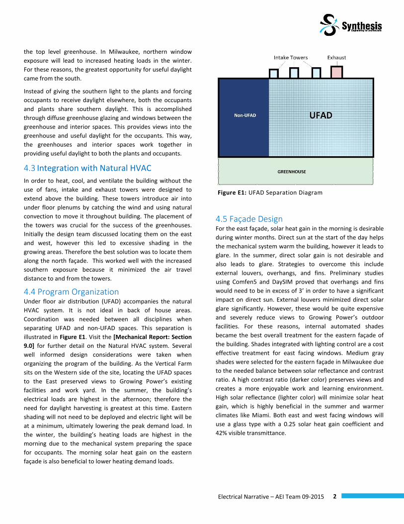
4.4 Program Organization Under floor air distribution (UFAD) accompanies the natural
HVAC system. It is not ideal in back of house areas.
Coordination was needed between all disciplines when
separating UFAD and non-UFAD spaces. This separation is
illustrated in Figure E1. Visit the [Mechanical Report: Section
9.0] for further detail on the Natural HVAC system. Several
well informed design considerations were taken when
organizing the program of the building. As the Vertical Farm
sits on the Western side of the site, locating the UFAD spaces
to the East preserved views to Growing Power’s existing
facilities and work yard. In the summer, the building’s
electrical loads are highest in the afternoon; therefore the
need for daylight harvesting is greatest at this time. Eastern
shading will not need to be deployed and electric light will be
at a minimum, ultimately lowering the peak demand load. In
the winter, the building’s heating loads are highest in the
morning due to the mechanical system preparing the space
for occupants. The morning solar heat gain on the eastern
façade is also beneficial to lower heating demand loads.
4.5 Façade Design For the east façade, solar heat gain in the morning is desirable
during winter months. Direct sun at the start of the day helps
the mechanical system warm the building, however it leads to
glare. In the summer, direct solar gain is not desirable and
also leads to glare. Strategies to overcome this include
external louvers, overhangs, and fins. Preliminary studies
using Comfen5 and DaySIM proved that overhangs and fins
would need to be in excess of 3’ in order to have a significant
impact on direct sun. External louvers minimized direct solar
glare significantly. However, these would be quite expensive
and severely reduce views to Growing Power’s outdoor
facilities. For these reasons, internal automated shades
became the best overall treatment for the eastern façade of
the building. Shades integrated with lighting control are a cost
effective treatment for east facing windows. Medium gray
shades were selected for the eastern façade in Milwaukee due
to the needed balance between solar reflectance and contrast
ratio. A high contrast ratio (darker color) preserves views and
creates a more enjoyable work and learning environment.
High solar reflectance (lighter color) will minimize solar heat
gain, which is highly beneficial in the summer and warmer
climates like Miami. Both east and west facing windows will
use a glass type with a 0.25 solar heat gain coefficient and
42% visible transmittance.
Figure E1: UFAD Separation Diagram

3 Electrical Narrative – AEI Team 09-2015
4.6 Greenhouse Adjacent Spaces Diffuse glazing selected for the greenhouse façade creates a
buffer before the daylight reaches interior spaces. Synthesis
views 100% of this daylight as useful because it is not glaring
and benefits the mechanical system greatly in both winter and
summer months See DaySIM analysis [Appendix G]. Although
there are periods of time during which points in the room
exceed 2,000 lux, there is little research available to support
this as the upper threshold of useful daylight1.
A 1-hr fire rated, 75% visible light transmitting glass has been
selected for spaces adjacent to the greenhouses. In addition,
translucent partitions will allow more daylight to reach the
middle corridor of levels 3 and 4. In the winter, growing areas
will be kept to a minimum of 70°. This effectively eliminates
conduction between the interior spaces and greenhouse. The
views from various classrooms and offices into the
greenhouse will help educate and add enjoyment to each
occupant’s experience.
5.0 Greenhouse Design The greenhouses are a key aspect of the Vertical Farm. With
the construction of the new building, Growing Power,
Milwaukee will become a catalyst for inspiring similar projects
nationwide. The success of the farm, and future facilities like
it, will ride heavily on the success of the greenhouse design.
Not only did Synthesis design the greenhouses for optimum
growing conditions, strong emphasis was also placed on
creating an environment for urban farmers alike to learn from
Growing Power; encouraging a new standard in greenhouse
design for the entire urban farming industry.
The Vertical Farm utilizes the entire Southern façade for
greenhouse space, with 4 stories of tiered greenhouses
climbing up the stepped face of the building. Each tier is
considered one greenhouse. Each greenhouse is comprised of
six modules. Figure E2 shows a rendering of one greenhouse
module. Although this report focuses on the lighting/electrical
design of the greenhouse, it is important to understand the
components of the modular greenhouse design. This system is
explained in further detail in the [Synthesis Integration
Report: Section 6.0].
The next few sections of the report explain how the
greenhouse has been designed with respect to the plants.
Through the use of effective glazing, operable shade curtains,
and tunable grow lights, the greenhouse creates a consistent 1 (A. Nabil, 2005a)
environment inside that adapts itself to the unpredictable
nature of the outside.
5.1 Daylight Metrics PAR - Photosynthetically Active Radiation
To gain direction on how to provide light in the greenhouse,
the team analyzed how plants actually receive and convert
light into usable energy as carbohydrates. It is important to
understand that it is not about maximizing the quantity of
light delivered to the plants, but more about the quality of
light that the plants receive. Just as humans need a balanced
diet, plants also need a balanced spectrum of light for good
health and optimum growth. Like the human eye, plants are
also sensitive to certain portions of the light spectrum. This
portion of the light spectrum is referred to as
photosynthetically active radiation or PAR, generally occurring
between 400-700 nanometers in wavelength2. Although the
human eye sees in the same range of wavelengths as plants,
their action spectra’s are very different from one another. The
two action spectra can be seen side-to-side for comparison on
the following page in Figure E3 & E4.
2 (International, 2013)
Figure E2: Rendering of a Greenhouse Module

4 Electrical Narrative – AEI Team 09-2015
Figure E4: Photosynthetically Active Radiation Curve
In the same way that fat provides the most efficient calories
for humans, red and blue light provides the most efficient
food for plants. However, a plant that is illuminated with only
red or blue light will fail to develop sufficient bulk and mass.
Therefore it is necessary to provide plants with natural light
that covers the entire spectrum, while also pumping the
output of the red and blue regions. Because the spectrum of
usable light is so different between plants and humans, the
same standards and metrics cannot be used. This PAR
spectrum is used to quantify the amount of usable photons
that plants are receiving and converting into carbohydrate
energy.
The PAR metric is measured in micromoles per meters
squared per second (µmol/𝑚2/s). This reports how many
moles (6 𝑥 1023) of light energy photons are being emitted
within an area of one square meter, every second. Many
lighting recommendations for plants are given in PAR, ranging
from 100-500 µmol/𝑚2/s depending on the plant species.
DLI – Daily Light Integral
Daily Light Integral (DLI) is the amount of PAR received each
day as a function of light intensity (µmol/𝑚2/s) and duration
(day). It is expressed as moles of light photons (mol) per
square meter (𝑚−2) per day (𝑑𝑎𝑦−1) or: (µmol/𝑚2/day). DLI is
an important variable to measure because it influences plant
growth, development, crop yield, and quality 3 . Routinely
monitoring the DLI received by crops is made possible through
the use of a LI-COR Quantum Sensor. This sensor extrapolates
the amount DLI at any point throughout the day and is used to
automatically activate the shade system and or supplemental
grow lights in the greenhouse.
3 (Torres & Lopez, n.d.)
5.2 Glazing Study In order to maximize the light efficiency in the greenhouse,
the Synthesis team sought to select a glazing material that
transmits the most amount of PAR, rather than the visual
spectrum of light. Unfortunately, most glazing manufacture’s,
including greenhouse manufactures, only report the visual
transmittance of their products rather than PAR
transmittance. As a way around this, the team used Window
7.2, glazing material software to build various configurations
of glazing systems. The respective spectral distribution reports
were then exported and further analyzed with respect to PAR.
This spectral report lists wavelengths from 300 – 830
nanometers, in increments of 5 nm, along with the
corresponding transmittance percentages for each listed
wavelength. These individual transmittance values depict the
percent of light, specific to each wavelength, the glazing
system transmits. Together using all of the transmittances,
over all the wavelengths in the spectrum, and using a D65 CIE
relative weighting distribution (visual daylight weighting
coefficient), the visual transmittance is calculated 4 . See
equation (𝜏𝑣𝑖𝑠𝑖𝑏𝑙𝑒) below:
𝜏𝑣𝑖𝑠𝑖𝑏𝑙𝑒 = ∑ 𝐷(𝜆)𝑉(𝜆) ∙ 𝜏(𝜆) ∙ 𝛥𝜆𝜆
∑ 𝐷(𝜆)𝑉(𝜆)𝜆 ∙ 𝛥𝜆
𝐷𝜆𝑉𝜆 : 𝐷65 𝐶𝐼𝐸 𝐿𝑢𝑚𝑖𝑛𝑜𝑠𝑖𝑡𝑦 𝑤𝑒𝑖𝑔ℎ𝑡𝑖𝑛𝑔 𝑐𝑜𝑒𝑓𝑓𝑖𝑐𝑖𝑒𝑛𝑡
This D65 CIE relative weighting distribution takes the human
eye’s spectral distribution into account and gives a weighting
to the transmittances for the specific wavelengths humans
see (Figure E4). The Synthesis team developed a similar
equation which uses a PAR weighting spectrum (Figure E5)
4 (Shimadzu, 2015)
Figure E3: Human Eye Response Curve

5 Electrical Narrative – AEI Team 09-2015
0
0.2
0.4
0.6
0.8
1
1.2
30
0
32
0
34
0
36
0
38
0
40
0
42
0
44
0
46
0
48
0
50
0
52
0
54
0
56
0
58
0
60
0
62
0
64
0
66
0
68
0
70
0
72
0
74
0
76
0
78
0
80
0
82
0
Tran
smit
tan
ce
Wavelength (nm)
PAR Spectrum
Glazing 1
Multiwall 2
instead of a D65 CIE weighting spectrum enabling the
calculation of the total PAR transmittance for the glazing
system. See equation (𝜏𝑃𝐴𝑅) below:
The glazing system was evaluated based on the total PAR
transmittance that was calculated and compared to the Solar
Heat Gain Coefficient (𝜏𝑃𝐴𝑅/𝑆𝐻𝐺𝐶 ). Ultimately, a diffuse
multiwall polycarbonate glazing system was selected as the
best option, not only providing efficient PAR transmittance
and low solar heat gain, but also diffusing and scattering the
sunlight through the multiple layers of the polycarbonate.
Diffuse light is desired in greenhouse applications because
plants will receive more uniform light within the space and
severe shadows are not cast by structural members, light
fixtures, and mechanical systems. Polycarbonate panels are
also extremely light weight in comparison to glass, enabling a
more adaptable structure that is more resistant to wind loads
in other climates.
5.3 Design Criteria In order to determine greenhouse design conditions, a plant
matrix was compiled with crops that are planned to be grown
in the vertical farm along with their respective lighting criteria.
As seen in the matrix, different plants require different
amounts of PAR and DLI that optimize growth and schedule.
The plant matrix served as a good way to organize the lighting
requirements for the crops Growing Power will be cultivating.
Table E6 shows the lighting portion of the plant matrix, see
[Appendix B] for the full matrix. The plants were organized
into three design conditions according to their respective
recommended Daily Light Integrals,
Level 2 Greenhouse = 14 mol/day
Level 3 Greenhouse = 20 mol/day
Level 4 Greenhouse = 26 mol/day
Level 5 Greenhouse = 14 mol/day
The three tiered greenhouses are designed for three different DLI values, creating a variety of growing environments for any type of plant. Because the majority of Growing Power’s food production will come from leafy greens, the entire roof and first tier (Level 2 and 5 Greenhouses) are designed for the optimal conditions of 14 mol/day. Grow lighting should be designed for no more than 10 W/sf in greenhouse applications5.
5 (Ciolkosz, 2014)
Figure E5: The spectral distributions for Glazing 1 (single pane clear glass) (𝜏𝑃𝐴𝑅 = .62) and Multiwall 2
(Polycarbonate double pane panels) (𝜏𝑃𝐴𝑅 = .76).
𝜏𝑃𝐴𝑅 = ∑ 𝛼𝑃𝐴𝑅(𝜆) ∙ 𝜏(𝜆) ∙ ∆𝜆 𝜆
∑ 𝛼𝑃𝐴𝑅(𝜆) ∙ ∆𝜆 𝜆
𝛼𝑃𝐴𝑅(𝜆): 𝑃𝐴𝑅 𝑤𝑒𝑖𝑔ℎ𝑡𝑖𝑛𝑔 𝑐𝑜𝑒𝑓𝑓𝑖𝑐𝑖𝑒𝑛𝑡

6 Electrical Narrative – AEI Team 09-2015
Table E6: Lighting recommendations portion of plant matrix
5.4 Supplemental Grow Lighting There are 54 LumiGrow Pro 325 fixtures are spaced over the
potential growing area in each greenhouse to provide an
average of 14 moles per day to the plants if running for the
entire 24 hour period. The LED grow lights emit photons at
wavelengths specific to the PAR spectrum, which supplement
the daylight (transmitted through the PAR optimized
polycarbonate glazing) absorbed by the plants. The fixtures
are also tunable in their spectral outputs, meaning that
Growing Power staff can easily manipulate the PAR outputs of
each fixture - specific to certain plants or grow periods. This is
beneficial because not all plants use the exact same PAR
curve. The PAR curve previously discussed is an average
absorption curve for carbon-three plants (leafy green
vegetables).
The fixtures are mounted at 7’ from the floor of the
greenhouse, 4’ from the calculated growing surface, and 1’
below the thermal divider. There will be 9 grow lights per
greenhouse module, hung from an adjustable metal chain,
and mounted to the supporting steel structure. See [Appendix
E] for more information on the grow lights and a mounting
detail in Figure E7. A Li-COR Quantum Sensor will be used in
conjunction with a data logging device (SmartPAR system) to
measure PAR throughout the day along with instantaneously
predicting the Daily Light Integral. The DLI and PAR values
read by the Quantum Sensor will dictate when and how often
the grow lighting will supplement the daylight to the plants.
The fixtures emit a specific PAR (𝜇𝑚𝑜𝑙 𝑚2 𝑠⁄⁄ ), therefore the
amount of light supplemented by the fixtures is a function of
how long they are on each day. For example, if the daylight
absorbed by the plants (measured by the quantum sensor) is
10 moles that day, the grow lights only need to supplement 4
additional moles to reach the target conditions for 14
moles/day; therefore they need to run for 6.8 hours that day.
This is explained in the following calculation:
𝐻𝑜𝑢𝑟𝑠 𝑜𝑓 𝑂𝑝𝑒𝑟𝑎𝑡𝑖𝑜𝑛 = # 𝑀𝑜𝑙𝑒𝑠 𝑁𝑒𝑒𝑑𝑒𝑑
𝐺𝑟𝑜𝑤𝑙𝑖𝑔ℎ𝑡 𝐷𝐿𝐼(𝑝ℎ𝑜𝑡𝑜𝑝𝑒𝑟𝑖𝑜𝑑)
Although the fixtures are each 325 watts, which creates a
connected lighting load of about 17,550 VA per greenhouse
(7.24W/sf average), the fixtures will only operate for 15% of
the year in the Level 2 and 5 Greenhouses, 32% of the year in
Level 3 Greenhouse, and 41% of the year in the Level 4
Greenhouse in order to meet the design criteria of 14, 20, and
26 mol/day respectively. [Appendix G]
Control System – Information from the Li-COR sensor is
collected in a central control processor as part of the
LumiGrow SmartPAR system. The controller is responsible for
calculating and predicting DLI from PAR sensor readings.
Control signals are sent wirelessly to individual LumiGrow
fixtures, and low voltage signals are sent to shade motors.
This control scheme is easily adjusted and managed by
greenhouse operators from laptops or tablets. Data from the
system will be continuously reported back to the building
management server via Ethernet.
Visual display screens linked to the building network server
will be mounted in each greenhouse reporting data read and
received by the Quantum Sensor. This will help visitors
compare growing environments while touring the facility as
each greenhouse has different target DLI values.
5.5 Operable Shade Curtain System Just as grow lighting is used to help supplement PAR to reach
the target DLI values for each greenhouse, a suspended shade
curtain will help block PAR on days that are over the target
Daily Light Integral. The shade curtains also have important
heat retention properties that are utilized at night when
heating demands are highest. The LudvigSvensson: Tempa
shade family uses alternating aluminum strips with polyester
fabric in a woven structure that creates excellent energy
savings, light shading, and diffusing properties. The aluminum
strips reflect infrared light out during the day and back into
DLI PAR Crop Type (Mol/Day/m2) (μmol/m2/s )
Lettuce 14 150-200
Basil 14 150-200
Beat Greens 14 150-200
Greens 14 150-200
Chives 14 150-200
Tomatoes 26 300
Cucumbers 20 250
Strawberries 20 250
Figure E7: Partial greenhouse section mounting detail

7 Electrical Narrative – AEI Team 09-2015
0
5
10
15
20
25
30
35
40
45
1-Jan 2-Mar 1-May 30-Jun 29-Aug 28-Oct 27-Dec
Mo
les/
Day
Date
Daylight + Shades + Grow Lights
0
5
10
15
20
25
30
35
40
45
1-Jan 2-Mar 1-May 30-Jun 29-Aug 28-Oct 27-Dec
Mo
les/
Day
Date
Daylight + Shades
the greenhouse at night, helping to both heat and cool the
environment. This type of material is desirable because it uses
a single-screen solution for shading, cooling and maximum
energy saving. Because each tiered greenhouse has different
design criteria, each will have a different shade cloth material
to shade or transmit the recommended PAR. The exact shade
cloth materials and specific mounting details are located in
[Appendix F].
For each module, the shade system is
comprised of two shade components:
one sloped shade mounted just below
the sloped glazing at the top, and one
vertical shade mounted on the southern
wall of the greenhouse. The two end
modules will also have side shades on
the east and west walls. The top, sloped shade will be
mounted to a horizontal steel member spanning between the
two trusses on either side of the module. The shade will
deploy down the slope of the glazing between the trusses on
either side of the module. An aluminum track is mounted
underneath either truss and secures each side of the shade
cloth. The track helps to keep the shade cloth taught at all
times and creates an air tight seal between the glazing and
the shade curtain. The vertical shade on the front wall deploys
from the bottom up; shading the entire exposed glazing area.
See [Appendix F] for mounting details.
The SmartPAR system will allow automated and scheduled
operation of all greenhouse shades. The motorized shades will
deploy and contract throughout the day, providing the correct
DLI to the plants. The Li-COR sensor will therefore be linked to
both the shade control and supplemental grow light control.
5.6 Greenhouse Performance A Daysim (daylight analysis software tool) model was
used to accurately analyze greenhouse performance over the
course of a typical year. The three graphs on the right show
the optimization of Greenhouse 2 (20 mol/day target). The
graphs plot the DLI inside the greenhouse each day over the
course of one year. The first graph shows the ambient
weather conditions the plants receive in the greenhouse
without the use of the shade curtain or supplemental grow
lighting. The next graph shows the effect that the shade
curtain system has on the Daily Light Integral, while the third
graph shows the final effect that both shades and grow lights
have on the DLI absorbed by the plants. Together, the
components of the greenhouse system create a consistent
environment (20 mol/day) inside the greenhouse despite the
changing sky conditions each day throughout the year.
0
5
10
15
20
25
30
35
40
45
1-Jan 2-Mar 1-May 30-Jun 29-Aug 28-Oct 27-Dec
Mo
les/
Day
Date
Daylight

8 Electrical Narrative – AEI Team 09-2015
6.0 Energy
6.1 Growing Power as an Ecosystem When designing a building that produces food for the
community, it is important to understand naturally occurring
agricultural ecosystems. Traditionally, plants live and grow in
soil, bearing fruits and vegetables each season. Once these
plants die, their remains break down and fertilize the very soil
in which they once thrived. The fertile soil serves as excellent
ground for new seedlings to sprout and begin the cycle over
again, thus creating a self-sustaining ecosystem.
Growing Power is an ecosystem within the community. They
currently import local food waste for composting soil and
fertilizer. In the Patterns developed by TKWA (architects who
provided the competition approved drawings) it was
expressed that Growing Power wanted to mimic the natural
cycle of food production, using food waste as a fuel source for
onsite energy production. This energy is directly used to
power the Vertical Farm, ultimately providing the community
with food. This establishes Growing Power an integral part of
the local ecosystem.
Figure E8: Growing Power as an Ecosystem
6.2 Anaerobic Digester An onsite anaerobic digester is responsible for creating biogas
from food waste collected from Growing Power’s existing
operations and other resources around the community, such
as universities, farms, and local businesses. Tipping fees
charged by Growing Power will be less than the local landfill,
thus offering a financial incentive for local businesses to
participate. The anaerobic digester is divided into two stages.
The first stage takes in food waste and produces three
outputs – biogas, solid fertilizer, and liquid fertilizer. The liquid
fertilizer is sent to the second stage digester where additional
biogas is produced and stored. The biogas is ultimately
combusted in a 200 kW microturbine in the building. The
excess fertilizer (solid and liquid) is harvested for composting
nutrient rich soil at existing greenhouse sites. Food waste will
be delivered daily to Growing Power. This will produce 2.2
million BTU per hour of biogas to be used to by the
microturbine.
6.3 Microturbine The 200 kW Capstone Microturbine is responsible for
generating electricity on site for the Vertical Farm. It not only
produces electricity for the building’s mechanical and
electrical systems, but it is also the prime mover in the quad-
generation scheme. The microturbine initially delivers 250
kVA at 480Y/277V to the building’s main switchgear, which
parallels with the WE Energies (Wisconsin Electric, local utility)
power grid to allow for excess electricity to be sold back to the
grid, or needed supplemental electricity to be drawn from it.
A microturbine was selected over an internal combustion
engine because of the small load associated with the peak
annual energy usage of 144 kW. The smaller physical size,
ultra-low emissions, and limited noise levels associated with
the microturbine were also beneficial. The microturbine has
the capability to run all of the time, regardless of food waste
supply and biogas fuel. In case of a food waste shortage,
Growing Power relies on a natural gas tie in, in order to keep
the microturbine running.
Biogas is a desirable fuel source because of its renewable
nature. It is not a resource that needs to be extracted from
the earth. Instead, it is already being produced every day by
the local residents and businesses in Milwaukee. See
[Mechanical Report: Section 5.0] for more information on
biogas as a fuel source for the microturbine.
As a result of the peak electrical demand being only 144 kW,
Growing Power will be producing far more energy than it will
be using. As Growing Power will be tied into the electrical
grid, they will be selling this excess power back to the utility.
For a detailed explanation on the overall power consumption
and production visit [Appendix H].
6.4 Quad-Generation A typical combined heat and power system is commonly
referred to as “co-generation”, however the Synthesis “quad-
generation” process describes a system that gives four
outputs: heat, power, cooling, and carbon dioxide. The
microturbine produces 200 kW of electricity and exhaust gas
that is directly used in a heat exchanger, to provide heating.

9 Electrical Narrative – AEI Team 09-2015
Heat will also be used in an absorption chiller, creating chilled
water used for cooling. The fourth output, carbon dioxide, is
the major component in the exhaust gas. The exhaust gas is
cooled and directly pumped into the greenhouses to elevate
CO2 levels. It is desirable because supplemental CO2
facilitates increased plant production in the closed
greenhouse system. Figure E8 below summarizes the quad-
generation process. For a more detailed explanation on the
quad-generation process visit the [Mechanical Report:
Section 6.0].
6.5 Photovoltaic Panels Arrays of stationary south facing photovoltaic (PV) panels are
mounted on the overhang extending from the Market. The
array faces Silver Spring Drive, along with the existing array to
the east of the building. Total connected power for the new
array is 17.5 kW DC6. The PV’s will be mounted on a 37° slope,
which is optimized for Growing Power, Milwaukee. This yields
some of the highest energy year round. Although the
optimized annual yield happens closer to 35°, the 37° slope
provides more energy during winter months. This is beneficial
because the Vertical Farm will require much more power due
to grow lighting in the winter than other times of the year.
The slope of the photovoltaic array and overhang will
decrease as the building is designed to be located closer to
the equator. For example, the optimal angle for Growing
Power, Miami will be 18°.
The market will be completely shaded from direct sun
between March 21st and September 21st, due to the PV array.
The limited solar heat gain in the summer and increased solar
6 (Energy, 2015)
radiation in the winter is desirable for heating and cooling
loads in the market space. A section of the building, and more
information about the photovoltaic panels is explained in
[Appendix L].
The payback period for this system will be slightly over 16
years, which is typical of static photovoltaic arrays, regardless
of the amount. Tracking panels were looked into as an even
more efficient means of harnessing sun energy, however the
function of the array as an overhang would be sacrificed and
the payback period would double. Although the payback is
longer than desired, the photovoltaic arrays on display in front
of the building advertise Growing Power as a green site to the
community.
7.0 Power Distribution Growing Power’s Vertical Farm will have three main sources
of energy, the 200 kW microturbine, a photovoltaic array, and
a tie in to the the utility company, WE Energies. These three
sources of energy each funnel into the building’s main
switchgear at 480Y/277 volts. From there the power is sent to
the basement mechanical loads (89 kVA) on the basement
distribution panel and the buildings 4 greenhouse panels (18
kVA each). The rest of the power is sent through a 112.5 kVA
208Y/120V transformer located in the basement electrical
room. From there, power is distributed to the buildings
general lighting, receptical, and simple motor loads via local
distribution panels on each floor. For a general overview of
the power system in the building and amore detailed
explanation of the main switchgear and distribution panels
see [Drawing E109].
7.1 Limited Mechanical Loads The entire building’s mechanical system loads amount to just
118 kVA (480Y/277V). Generally for a building of this size and
function, the loading would be considerably higher. However,
the mechanical system functions primarily through wind
pressure and thermal buoyancy principles, thus reducing fan
energy. The second floor and above are heated and cooled
using a natural HVAC system utilizing the custom designed air
intake towers and exhaust chimney in the rear of the building.
The use of an absorption chiller eliminates the need for a
large refrigerant compressor. The largest mechanical load on
the electrical system is the conservatively sized 50
Horsepower (60 kVA) groundwater pump from the
geothermal well back to the building. It accounts for more
than half the entire electrical load of the mechanical system,
and is so large because of how deep the well is and how far
Figure E9: Quad-Generation Process

10 Electrical Narrative – AEI Team 09-2015
the water needs to be pumped back to the building.
[Appendix H]
7.2 Load Classifications Basement Equipment Loads – The large mechanical loads in
the basement of the building run on 480Y/277V power. The
mechanical system components are detailed in the
mechanical equipment schedule in the [Synthesis Mechanical
Drawing: M110].
General Loads – Smaller loads in the building that run on
208Y/120V: receptacles, lighting fixtures (except for
greenhouses), audiovisual, small motor loads, and kitchen
equipment.
Priority Loads – All greenhouse receptacles and lighting
fixtures are considered priority loads, as well as any
connected load related to the operation of the aquaponic
systems and shade control motors. It is important to keep the
greenhouse loads separate from the general building loads in
cases of reduced energy availability.
Emergency Loads – This includes anything related to life
safety and means of egress. This is comprised primarily of
emergency lighting (which by code requires 0.2 w/sf lighting
and 2 fc egress paths), and fire protection loads. Emergency
lighting and exit signs contain small integral 1.5 hour battery
packs.
7.3 Emergency Power It is important to the Quad-Generation scheme that the
microturbine stays up and running at all times. Therefore, the
emergency power for the building will be in the form of
natural gas. If biogas ever becomes unavailable the fuel
source for the microturbine will switch from biogas to utility
natural gas. This is a deemed a reliable emergency fuel source
by the local jurisdiction because pipeline interruption is highly
unlikely. The microturbine is designed specifically for this
application and has two fuel source inputs.
Although the electrical system is sized to 365 kVA, and the
microturbine will be producing 250 kVA (0.8 power factor),
the system will rarely be running at full load. This is beneficial
because the microturbine will be able to provide all of the
power to the building the majority of the time. The 17.5 kW
photovoltaic array provides power to the system when solar
radiation is available. There will be few peak electrical load
instances when Growing Power will need to draw power from
the electrical grid.
Worst Case Scenario – Although the natural gas grid is
deemed reliable, there is still a possibility that outages occur
due to gas line repairs, natural disasters, digging damages,
and gas leaks7. In the case of a biogas, natural gas, and
electrical outage the Vertical Farm has the necessary life
safety requirements by the NEC 2011 and Wisconsin
Administrative Code for occupants to safely exit the building.
Battery packs have been added to the necessary fixtures in
order to achieve a uniform 2 fc illuminance in the necessary
means of egress.
7.4 Electrical Room Coordination As Synthesis redesigned the building the team was able to
place the electrical rooms, main mechanical shaft, and IT
rooms adjacent to core spaces (stair and elevator shafts). This
allows backbone cabling and piping to be erected early in
construction before interior partitions. The electrical rooms
are located in the Southwest corner of the Vertical Farm.
Although the electrical rooms are not perfectly stacked, they
remain in close vicinity to one another, minimizing feeder runs
and saving time and money during construction.
7.5 Smart Distribution Panels All panels in the building will be intelligent for controllability
and data collection. Each incorporates a processor within each
branch panel that is linked to a local IT room’s IP switch. The
data link allows each individual circuit on the panel to be
controlled and metered by the building automation system via
BacNET/IP. Through this method Growing Power will have a
full understanding of how the Vertical Farm is using energy.
Occupancy Control – Occupancy control over lighting is
accomplished using a digitally addressable lighting interface
(DALI) control protocol. Up to 64 devices, regardless of
location and circuit, can be individually controlled through
DALI. This is beneficial because light fixtures do not need to be
circuited with regards to controllability and installation is
simple. Micro controllers receive data from local occupancy
sensors, vacancy sensors, photosensors, and DALI
wallstations. Each device has a digital address, and each
address is programmable. This however, is not the case for
receptacles.
In order to control branch circuit receptacles by occupancy
sensor, the receptacles need to be circuited according to the
room the occupancy sensor is serving. Therefore each room
has a single branch circuit for its receptacles. The occupancy
sensor speaks to the DALI microcontroller via radio frequency
7 (Company, 2015)

11 Electrical Narrative – AEI Team 09-2015
signals. This information is sent to a relay device on the DALI
bus which will switch power to room receptacles (Figure 5). As
a result, all receptacles will be switched on or off based on the
occupancy sensor. This system is useful for limiting “phantom”
plug loads that are not necessary after hours. The occupancy
sensor override to the main time clock helps prevent this by
cutting power to receptacles. [Appendix N]
Metering – The smart panel system monitors and reports
power consumption of each branch circuit. At all times, the
panel meters the flow of current and instantaneously reports
this data back to the building management server. This will aid
Growing Power in understanding the exact energy break
down of the building.
7.6 Raised Access Floor There will be a raised access floor on levels 2-4 where under
floor air distribution (UFAD) will occur. The Natural HVAC
system utilizes air intake towers in the rear of the building to
introduce outside air into the plenum. The electrical benefits
to this system are as follows:
Building adaptability – If floor plans change over time, the
receptacle layout is much easier to modify compared to hard
wiring everything through permanent partitions.
Shorter runs – Instead of wiring wall mounted receptacles
through the ceiling plenum and down inside the partition, the
contractor can run conduit more directly to the load, creating
shorter overall run lengths.
Easier to install – Because the conduit takes a more direct
route, it saves the construction team time and money when
installing.
Localized Load Placement – With a raised access floor, it
becomes much easier to place receptacles and other hard
wired loads directly where they need to be.
8.0 Lighting Design
8.1 Concept & Overview The lighting system has been designed with three key factors
in mind, efficiency, controllability, and aesthetics. It has been
designed in accordance with ASHRAE 90.1 (2011), Title-24
(2013), NEC (2011), and in conjunction with standards from
the IES Handbook (10th Edition). Design criteria were
developed through a combination of the most stringent
energy codes in the country. This ensures that no matter
where Growing Power decides to build their next vertical
farm, the lighting will meet the local jurisdiction’s code with
minimal changes.
8.2 Color Rendering Criteria for color rendering were developed through ASHRAE
design guides and related research. Color Rendering Index
(CRI) has been recently used to determine the ability of a light
source to render color similar to that of daylight. The linear
nature of this metric, makes it a simple single metric for
determining color rendering capabilities of artificial lighting. A
CRI of 90+ was determined to be an achievable goal with long
lasting benefits as lighting becomes more advanced.
The energy efficient Vertical Farm pushes the envelope in
emerging technology by lighting with the most modern
sources. However due to the process by which LED’s produce
light, they typically fall behind other light sources when
rendering red colors. For this reason additional criteria was
developed for the market, where customers will be selecting
colorful foods based on the way they look and feel. R9 and
MacAdam binning are important metrics when designing the
market lighting. R9 performance represents the ability for a
light source to render reds, and similar MacAdam binning
values between fixtures reduce noticeable color variation.
This means that fixtures selected for lighting food in the
market will have truly similar color rendering properties
(similar chromaticity values).
Track and aisle lighting in the market within 3 MacAdam steps
of one another was selected with an R9 value of 50+. White
light sources outside of a 3 step MacAdam from one another
lead to noticeable color variation, therefore the strict binning
criterion was developed.
Figure E10: Branch Receptacle Control

12 Electrical Narrative – AEI Team 09-2015
8.3 Efficiency The entire lighting system for the building beats the best of
Title-24 and ASHRAE standards by at least 15% for both space-
by-space and whole building LPD. This meets the most
stringent ordinance in the US (San Francisco), which requires a
15% better LPD than Title-24. The Milwaukee lighting system
will remain as a constant part of the design when relocating
the Vertical Farm to anywhere in the country. All of the
lighting fixtures are long lasting, efficient LED sources, using
minimal connected load. Overall, interior lighting amounts to
2% of the building’s annual energy usage, and 0.25 W/sf.
[Appendix J]
8.4 Controllability Lighting Control – The lighting design is broken up into three
components of controllability. 0-10V, digital addressable
lighting interface (DALI), and electronic low voltage (ELV).
Back of house fixtures have simple auto-on/auto-off control
via passive infrared (PIR) occupancy sensors. Market general
lighting utilizes 2 zone daylight harvesting with 0-10V dimming
for maximum energy savings. All track lighting is easily
controlled by market employees via ELV, or reverse phase
dimming on two circuits.
All other lighting in regularly occupied spaces is controlled
through DALI interface. This is an open protocol, which allows
flexibility in fixture selection and control architecture. Groups
of individually addressable light fixtures have been put into
control loops for local control at wallstations. These are
located in offices, classrooms, meeting rooms, and gathering
areas to allow for easy occupant control of scenes and
dimming. Photosensors and occupancy sensors are tied to
DALI microcontrollers to enable energy savings through
daylight harvesting and PIR sensing. Spaces along the east
façade utilize photosensors to minimize over dimming that
may occur due to snow cover8. Third party shade motors are
given commands via Ethernet to maintain useful daylight
levels in spaces adjacent to the greenhouses and along the
eastern façade. [Appendix M]
Growing Power employees will have local lighting control
from smartphones, tablets, and laptops. Individual DALI
microcontrollers will speak back to a full floor processor and
are linked to a patch panel. The patch panel speaks back to
the main IT room on the 2nd floor through fiber where data
can be transferred to other servers. Through this method each
8 (Mistrick & Chen, 2014)
DALI control processor exchanges information with the
building network server.
8.5 Offices, Classrooms, & Gathering Areas Energy efficiency and visual comfort are key in spaces that
may be used for long periods of time. Many of the interior
spaces above the first floor utilize direct/indirect lighting for
task and general illumination. The indirect component creates
a comfortable environment for gathering space attendees,
students, and administrative workers. Light diffused by white
ceilings is spread evenly throughout task planes to provide
soft illumination and minimize laptop or cell phone screens.
The down light component works in harmony with the
indirect lighting by providing an extra punch of light onto the
work surface. This provides higher delivered lumens (to the
work plane) per watt than strictly indirect lighting9.
8.6 The Market The market is the culmination of the hard work at Growing
Power. Here, Growing Power will not only display and sell
organic food, but also promote and educate the community
about sustainable agriculture and modern urban farming. The
lighting, in conjunction with the architectural configuration of
the space, creates a stimulating market environment that
embodies all that Growing Power stands for.
Eye on the prize – Emphasis on the food is the main goal. High
color quality with minimal perceived variation is achieved
through fixtures which adhere to the design criteria
mentioned in section 8.2. Contrast (3:1) is maintained
between the task and aisle illuminance to create a more
dramatic presentation of the final products being sold.
The open floor plan allows visitors to move freely throughout
the space. 4’ moveable tables are accessible from four sides
and display the variety of food options Growing Power offers.
They are organized in a grid and are enhanced by the two
lighting sources above.
General illumination is provided by the linear downlights
mounted between tables and above the aisle ways at 10’.
Unlike typical linear downlights, the Ammerlux Producer
fixtures emit a desirable “bat-wing”
beam spread that extends light further
away from the fixture on either side
(Figure E11). This distinctive beam
spread is effective in retail applications
because it provides illumination to both
9 (Alera Lighting, 1995)
Figure E11

13 Electrical Narrative – AEI Team 09-2015
the floor and the display to either side.
Track lighting is an adaptable lighting solution that provides
the necessary emphasis on the food tables no matter their
configuration. This scheme is used to accent the food and
focus the customer’s attention. In the display area there is a
continuous grid of Ammerlux single circuit 120V track, hung at
10’. Mounted to the track are 2200 lumen adjustable fixtures
with a 30° beam spread. Together, the linear downlights and
track fixtures combine to provide 50 fc of illuminance on the
display tables and 17 fc in the aisles. Although the IES
recommends a 10 fc average illuminance in the aisle, a
contrast of 50 fc to 10 fc (5:1) would cause the floor to appear
dark, thus the contrast ratio has been designed to 3:1.
Seafood Counter – The Seafood Counter on the western wall
of the market serves fresh perch and tilapia that are raised in
house through aquaponic production. It is pronounced by an
architectural ceiling header that drops below the rest of the
exposed ceiling in the display areas. A concealed portion of
track is mounted behind the header concealed from view and
back lights the signage on the rear wall. Circular downlights
illuminate the work area. The concealed lighting and the
architectural change in ceiling heights help to distinguish the
Seafood Counter as a significant component to the market.
Checkout Counter – The Checkout Counter sits opposite the
Seafood Counter on the eastern wall of the market. An
architectural header is used to signify the counter’s presence
in the space along with hanging pendants mounted at 7.5’. A
row of pendants line the counter top and bring the light down
to a local level creating a warmer interaction between the
consumer and the Growing Power cashier.
The incoming daylight from behind the counter will create a
high contrast between the background and the cashier’s face,
leading to less distinguishable features. Introduction of the
pendants reduces this contrast and preserves the interaction
between the two by providing vertical illuminance on the
cashier’s face and balancing out the daylight. Figure E12
describes this scenario.
Figure 6: Market Checkout Section
Building Education Dashboard – Along the north wall of the
market there is a wall devoted to educating community
members and other visitors about Growing Power’s energy
consumption. The wall incorporates an architecturally
pronounced extrusion that houses the building dashboard
display screens and is serviceable from behind. This extrusion
is lit from behind using linear LED cove lights creating a
glowing effect that emits on all three sides (bottom meets the
floor). See [Appendix L] for feature wall lighting and
dashboard details.
Using the QA Graphics interface, Growing Power will display
their data using a template created specifically for them. The
Building Education Dashboard will present real time data
about energy consumption of the building and specific
components (i.e. lighting). Growing Power will be able to
display metrics to show the overall efficiency of the Vertical
Farm ecosystem. For example, with collected data from
market cash registers and package scanning, the dashboard
could display lbs of food sold per lbs of food waste received.
When presented in a well-organized and intentional manner,
this information will effectively educate visitors and other
aspiring urban farmers who visit Growing Power. As they
monitor and report more and more data, drawing trends
across disciplines will become a constant theme. Growing
Power will begin to make these connections and learn from
their habits as the farm evolves into the future.
9.0 SMART Building Design Growing Power must embrace data as a resource for self-
improvement. Typical building systems (security, AV, HVAC,
lighting…) are organized as stand-alone operations. Meaning
the systems are uninfluenced by one another and function
entirely on their own. This building model does not work as an
organized unit.
Systems within the Vertical Farm will not function in this way
and instead they are converged over a single IP network. The
various systems will have influence over one another. This
allows for:
Figure 5: Market Section

14 Electrical Narrative – AEI Team 09-2015
Improved productivity
Improved user experience
User education
Reduction of energy usage
The Vertical Farm is one of the first of its kind. Growing Power
seeks to implement a network of vertical farms around the
country. As a prototype building, Growing Power must learn
from each implementation throughout the process. In order
to begin, the Milwaukee Vertical Farm needs to be analyzed
and evaluated. What is learned will not only improve future
vertical farms, but also continuously optimize Growing Power,
Milwaukee.
9.1 BIG Data In order to improve Growing Power must collect information
about energy use, system operation, and business
management. The converged IP network brings all
information back to a central hub of data collection servers.
Network Architecture – Multiple systems within the building
are ultimately tied together through fiber connections. This is
the backbone cabling for the entire system. The fiber is run
from the main server room (2nd floor) to local IT rooms on
every other floor. A CAT 6A patch panel in each IT room works
as the link for various building operations. Each floor’s
network IP switch and BacNET/IP switch are cross-patched to
transfer data between devices, controllers, and servers. In the
main server room, multiple servers are cross-patched
together (local area network). Included with these will be data
collection servers so that information about building
operation and user interface is stored. Growing Power will use
this information to continuously improve productivity.
9.2 Full Building Automation Implementing SMART building system integration will require
additional programming and applications for controllers and
databases. The Synthesis Lighting/Electrical design team
recognizes this and has put in place the infrastructure for a
truly intelligent smart building. This means that no matter
what level of smart building Growing Power chooses to
implement, higher sophistication can easily be adopted.
The Integrated Building (Level One) – Information will be
shared between building systems though the building
automation server. Example:
Occupancy sensor will effect both lighting and HVAC
control
The SMART Building (Level Two) – Information is exchanged
between user applications and the building
automation system. Example:
The building calendar application will adjust the
HVAC system in the gathering space to pre-cool
before large events. This will counter the effect of
latent load and minimize work done by the system
Growing Power officials get system alerts via email or
smartphone application
The Informed SMART Building (Level Three) – Information will
be shared between building systems through the
building automation server. Example:
Growing Power has a better understanding of how
energy is being used. lbs of food sold vs lbs of food
waste used for energy
The Intelligent SMART Building (Level Four) – Normalized
data collection is used a means to improve each
Growing Power site. Trends are identified by
applications and adapted to automatically. Example:
The system learns typical occupant behavior
[Appendix O]
10.0 Design Adaptability The Growing Power Vertical Farm has been designed first for
its current location at 5500 W. Silver Spring Dr. Milwaukee,
WI. Growing Power views the new Vertical Farm as the first of
its kind and aims to establish it as a local and national
resource for sustainable urban farming education. With the
average age of farmers at over 65 years of age10, Growing
Power believes they are responsible for educating the youth
across the country. As founder Will Allen states: “our goal is a
simple one: to grow food, to grow minds, and to grow
community11.”
The farm has been designed as a prototype model to inspire
other Vertical Farms around the country. Although Synthesis
has designed the building for any climate, Growing Power
requires a specific plan for the next possible farm to be
located in Miami, Florida. This section describes how the
prototype will adapt to the new Miami location.
10.1 Daylighting The architectural layout and programming of the prototype
has been designed with daylight in mind for any geographical
location. Results of moving to Miami are as follows:
The Grand Outdoor Central will be moved to the
eastern side of the building to warm it in the morning
and keep it cool in the evening.
10 (Growing Power, Inc., 2014) 11 (Growing Power, Inc., 2014)
15 Electrical Narrative – AEI Team 09-2015
South facing rooms with greenhouse views will
receive less daylight in Miami than Milwaukee due to
the amount of time the greenhouse shades will be
deployed.
As in Milwaukee, the shade operation schedule will
depend on the PAR transmittance of the
polycarbonate glazing.
Aluminum louvers will be needed for east facing
windows. Shade operation with daylight harvesting
will work with this to minimize solar glare and
preserve views.
North facing windows should now be introduced
between the Natural HVAC intake towers. The new
windows will deliver useful indirect daylight into the
building without the effect of heat loss.
10.2 Greenhouse Design The closed, modular greenhouse design creates an adaptable
system that functions well in any climate around the country.
The greenhouse module will adapt to its new environment in
Miami in the following ways:
The same angle of glazing will let in more useable
PAR light due to a lower angle of incidence.
As more PAR light will be admitted, a lower PAR
transmittance glazing is desired if designing for
current target DLI set points.
Solar Heat Gain admitted by the glazing will be higher
with the current polycarbonate material, however
the cooling system is designed to handle this
increased load as designed for Milwaukee.
The current 25mm polycarbonate thickness preforms
well against wind loads in Miami.
Grow lights will still be configured in the same
manner, however they will be used less due to the
ample amount of useful daylight available year
round.
Shade system will use the same mounting and
deployment methods, however the shade cloth
material will change with respect to the new
polycarbonate PAR transmittance.
10.3 Energy The Miami Vertical Farm will function using the same quad-
generation scheme as Milwaukee. The size of the anaerobic
digester and microturbine will remain the same.
Before selecting a site, Growing Power must secure
initial contracts and agreements with local food
waste providers. This will ensure a continuous supply
of food waste for the digester.
The natural gas grid will continue to be a secondary
fuel source for the microturbine.
The electrical grid will still be paralleled with the
microturbine so that Growing Power can buy or sell
energy as needed.
Because Growing Power will be providing around 42% of its
annual electrical generation to their existing facilities,
Growing Power will have a large excess amount of power in
Miami. The location of the Vertical Farm should be
coordinated with the implementation of a new community,
developing a micro grid and creating an ecosystem
encompassing both. The new community will receive excess
power from the Vertical Farm as well as a healthy food supply,
in turn they will provide Growing Power with a constant
source of food waste.
This model should be the basis for new urban development
and will help spawn numerous similar operations like it,
creating healthy self-supporting urban ecosystems. [Appendix
H]
10.4 Electrical, Lighting, and Controls The power distribution scheme will remain the same when
relocating the Vertical Farm to Miami. The lighting power
densities meet and any code that would potentially be
required in the United States, including Title 24 2013
standards for plug and lighting control. The only changes that
would need to occur would be changing wire sizes to meet
voltage drop requirements of the local jurisdiction.
11.0 Conclusion The lighting and electrical system educates the buildings
occupants and Growing Power itself through the use of data
collection and SMART building controls. The efficient lighting
and quad-generation establishes Growing Power as an
ecological presentence in the Milwaukee community. And the
adaptable nature of the building’s daylight, greenhouse, and
lighting components all contribute to the prototype nature of
the Vertical Farm. The combination of these outcomes creates
a model urban farm for Growing Power and the entire
industry.