Embed Size (px)
Citation preview
engineering intelligent solutions
www.lucyelectric.com
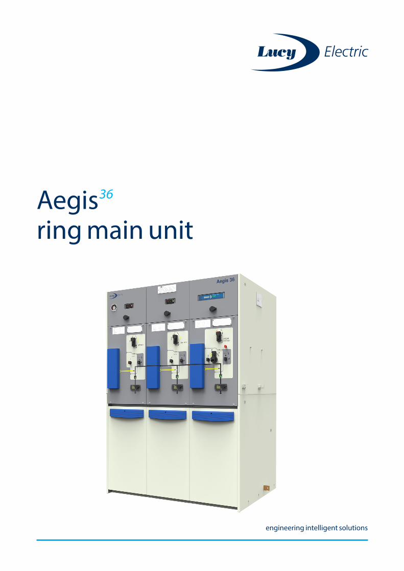
Aegis36 ring main unit
engineering intelligent solutions
Page 3
To find out more about us, visit:
www.lucyelectric.com
+ Flexible and cost effective
+ Safe and intuitive operation
+ Compact design
+ Indoor and outdoor installation
+ Automation ready
+ Easy to install
+ Climate independent
+ Wide range of protection relays, VPIS and VDS
+ Virtually maintenance-free
+ Wide range of options and accessories
Contents
Aegis 36 builds upon the strong foundations of the Aegis product family to provide the right features for our customers:
Introduction to Lucy Electric 4
Product panorama: Medium voltage and high voltage range
5
Introduction to Aegis 36 6
Installation and operating conditions 7
Safety features 8
Applications 9
Aegis range presentation 10
a. Available functions
b. Non extensible range
c. Extensible range
d. Extensibility system
Product Characteristics 13
Aegis presentation (fascia labelled) User interface and interlocking mechanism
Load Break Switch: L 15
Line diagram Standard features Optional features
Circuit Breaker: V 16
Line diagram Standard features Optional features
Circuit breaker protection 17
Protection relays
Options and accessories 19
Earth fault and short-circuit indicators Voltage presence indication system Voltage detection system Secondary injection Actuators (motors) Shunt trip coils
Cable bushings and cable terminations 23
Cable bushings Cable compartment Cable terminations
Air metering unit 25
Internal arc protection 27
Smart-grid ready 28
Gemini 3 RTU characteristics Added functionality and benefits Automatic transfer scheme
Technical data 30
Dimensions 31
Order form 32
Page 5 Page 4
24kV Vacuum/ HV fuse
SF6 630AGround /
TransformerIndoor / Outdoor
Local / RemoteAegisPlus
Lucy Electric is a global leader in switching, protection and automation solutions for electrical distribution systems, with over 100 years’ industry experience. Today the company is a specialist in secondary power distribution, engineering high-performance medium voltage switchgear for utility, industrial and commercial applications, overhead line equipment and providing retrofit and automation solutions to customers internationally.
Engineering excellence, based on a long tradition of expertise, coupled with state of the art technology to meet customers’ stringent specifications, make Lucy Electric one of the few companies that can offer truly bespoke solutions. We have the
capability to manufacture units for any location, climate or situation and offers a complete product portfolio, with a wide scope of services and dedicated after sales support throughout the product lifecycle.
A specialist UK research and development facility, with a continuous programme of R&D, ensures that Lucy Electric products are always at the cutting edge, designed to anticipate the evolving technical and market demands of our customers. And our multi-million pound, purpose built, state of the art UK manufacturing facility provides complete control over production.
Lucy Electric is a truly international company with offices in China, Thailand, Dubai, Malaysia and South Africa; manufacturing facilities in the United Arab Emirates, Saudi Arabia, Thailand and India; and an established global network of industrial partners and contractors operating in over 50 countries worldwide.
Introduction to Lucy Electric
1965 1970 1975 1980 1985 1990 1995 2000 2005 2010 2015 2020 2025
Scimitar
Trident
Ring main unit range evolution
Sabre
Aegis
Aegis
Product panorama: Lucy Electric medium voltage and high voltage range
Ratedvoltage(up to)
Mode offault current interruption
Insulationmedium
Ratedcurrent(up to)
Mounting Installationcondition Operation
24kV Vacuum SF6 630AGround /
TransformerIndoor /Outdoor
Local /RemoteSabre
15.5kV Fuse Oil 630AGround /
TransformerIndoor /Outdoor
Local /RemoteTrident
17.5kV Fuse SF6 630AGround /
TransformerIndoor /Outdoor
Local /RemoteScimitar
Ring main units
36 kV Vacuum SF6 Ground Indoor / Outdoor
Local / RemoteAegis 36
Air Metering Units
15.5 kV Oil 630 A GroundOil
15.5 kV Air 630 A GroundSabre
24 kV/36 kV
Air 630 A GroundIndoor/Outdoor
Indoor/Outdoor
Indoor/Outdoor
Plus
36
630A
Aegis Plus/ Aegis 36
Page 7 Page 6
Aegis 36 is Lucy Electric’s latest product, originating from the very successful Aegis product family. It is specially designed for secondary distribution networks, wind farms and photovoltaic power stations with ratings up to 36 kV. This range is available for indoor and outdoor environments, suiting various application needs. Aegis 36 offers high levels of reliability and operator safety. It is a compact, cost-effective and virtually maintenance-free product.
Aegis 36 offers numerous functional configurations insulated in a single robot-welded sealed tank. This robust range has been built for the toughest environments, with an option to convert units from indoor to outdoor, extending its environmental protection rating.
All of these enhancements have been achieved whilst reducing the spatial footprint, resulting in a design that is more compact and easy to install.
Characteristics:
• 36 kV and 630 A ratings
• Extensible and non-extensible range
• Flexible arrangements of functions, providing the exact solution
• 1 to 4 functions in a single SF6-insulated stainless steel enclosure
• Hermitically sealed stainless steel switching chamber
• No on-site SF6 gas handling for installation
• Intuitive single-line mimic diagram
• Vacuum interrupter technology for circuit breakers
• Suitable for indoor and outdoor applications
• Circuit breaker protection using a wide range of self-powered and auxiliary relays
• Motorisation for remote control
• Easy integration with SCADA networks
• Front access cable terminations, with DIN 400 Type C bushings
• Earth & Test facility
Introduction to Aegis36
StandardsAegis 36 complies with the latest international standards:
IEC 62271 – 100 Alternating current circuit breakers
IEC 62271 – 102 Alternating current disconnectors and earthing switches
IEC 62271 – 103 Switches for rated voltages between 1kV and 52kV
IEC 62271 – 105 Alternating current switch fuse combinations
IEC 62271 – 200 AC metal enclosed switchgear and control gear
IEC 62271 – 206 VPIS systems for rated voltages between 1kV and 52kV
IEC 62271 – 1 HV switchgear and control gear: common specifications
IEC 61243 – 5 Voltage detecting systems (VDS)
IEC 60255 Measuring relays and protection equipment
Installation and operating conditions
• Indoor and outdoor type units
• Maximum altitude of operation without derating 1000m (above sea level) *
• Installation medium: SF6 Gas
• Rated pressure at +20°C: 0.04 mpa
• Interruption medium = vaccum
* For higher altitude application please contact your local Lucy Electric sales office
IP 54 - Outdoor IP 41 - Indoor
Page 9 Page 8
Operation mechanism
The mechanism consists of one operating shaft and one selector. The operating shaft is used for switching ON / OFF (Mains or Earth) and the selector is used for selection of the Mains or Earth positions. It is impossible to simultaneously close the Load Break Switch / Circuit Breaker and the Earth switch.
The mechanism incorporates mechanical interlocks and padlocking facilities to improve operational safety and security.
Safety features
Earth and test facility
The cable earth and test facility is an optional feature on the Load Break Switch and the Circuit Breaker. It is located at the front of the unit for ease of access. It is used for testing cable insulation and to locate faults in the circuit without the need to remove the main cables from the cable compartment, which improves the operator safety.
The cable test access cover is fully interlocked and cannot be opened until the Load Break
Switch or Circuit Breaker Switch is in the Earth ON position. The test bushings are earthed with a star bar which has to be removed for cable tests.
Cable compartment
The cable compartments are located at the front of the unit with horizontally mounted DIN 400 Type C bushings for ease of cable connection.
For enhanced operator safety, the cable compartments are earthed and fully interlocked, allowing operator access only if the function is in the Earth ON position. There is an option to select these cable compartments with Internal Arc ratings as per IEC standard.
Anti-reflex mechanism
Ensures a time delay between switching operations to allow sufficient time for the main (primary or upstream) breaker to trip and clear a fault.
Earth stud in cable compartment
A fully rated earth stud is fixed inside the cable compartment, located towards the bottom of the unit. It is used for connection to the main earthing system.
Internal Arc withstand
The SF6 gas insulated, stainless steel tanks are fully internal arc rated and this feature is also available on the cable compartments (optional) to ensure maximum operator safety in the event of internal faults. As standard, Aegis 36 units are rated for AF (operator safety from the front of the unit), AFL (front and lateral), and AFLR (front, lateral and rear).
For more details please refer to the internal arc protection page 21.
Gas pressure indicator
• A gas pressure indicator is fitted to the tank which has green and red sectors to indicate the minimum permissible pressure for safe operation
• An optional remote gas pressure alarm (1N/O) can be specified to alert the operator in the event of gas pressure falling below the permissible operable limit
• Temperature compensated gauge available as an option.
Aegis 36 has been designed and developed for optimal performance in a range of applications, from diverse industrial requirements to power generation and distribution.
Power Generation and Distribution
i. Ring Main network protection
ii. Wind farms
iii. Photovoltaic power stations
iv. Co-generation facilities
Industries
i. Mining
ii. Automotive
iii. Iron and steel
iv. Paper and pulp
v. Cement and petroleum
vi. Water and waste water
Commercial Buildings
i. Shopping centres
ii. Hospitals
iii. Schools
iv. Hotels
v. Office buildings
vi. Warehouses
vii. Data centres
Infastructure
i. Metro stations
ii. Railway stations
iii. Airports
iv. Seaports
v. Tunnels
Applications
Page 11 Page 10
Aegis36 range presentation
Non-extensible range
This range is available in 3 and 4 functions, for both indoor and outdoor formats. This solution is perfectly suited for integration into compact substations to form standard ring main secondary networks with transformer protection. The range features switching and protection functions.
Available functions:
Switching function:
L: 630A Load break switch
Circuit breaker function:
V: 630A Vacuum circuit breaker
Test cable
Disconnector
Circuit breaker
Test cable
Disconnector
Aegis36 range presentation
Extensible RMU range
The extensible range enables the addition of further functions to the left, right or both sides of switchgear installed in secondary networks.This range has 1, 2, 3, and 4 functions insulated by SF6 gas in a single, hermetically sealed stainless steel tank. It is an ideal solution if additional functions are required at present, and provides freedom for further additions into the future.
Available in indoor (IP41 and IP54) format, these units can be easily extended in any combination on-site, without specific tooling or floor preparation, and without the need to transfer SF6 gas.
1 - function unit 3 - function unit
1 + 3 - function unit
Page 13 Page 12
Extensibility system
Top extensibility IP41 and IP54
Top extensibility can also be achieved by DIN 400 Type C bushings located on the top of the unit. The busbar connection is earth-screened (non-screened available as option). Suitable for both indoor (IP41) and outdoor (IP54) installations.
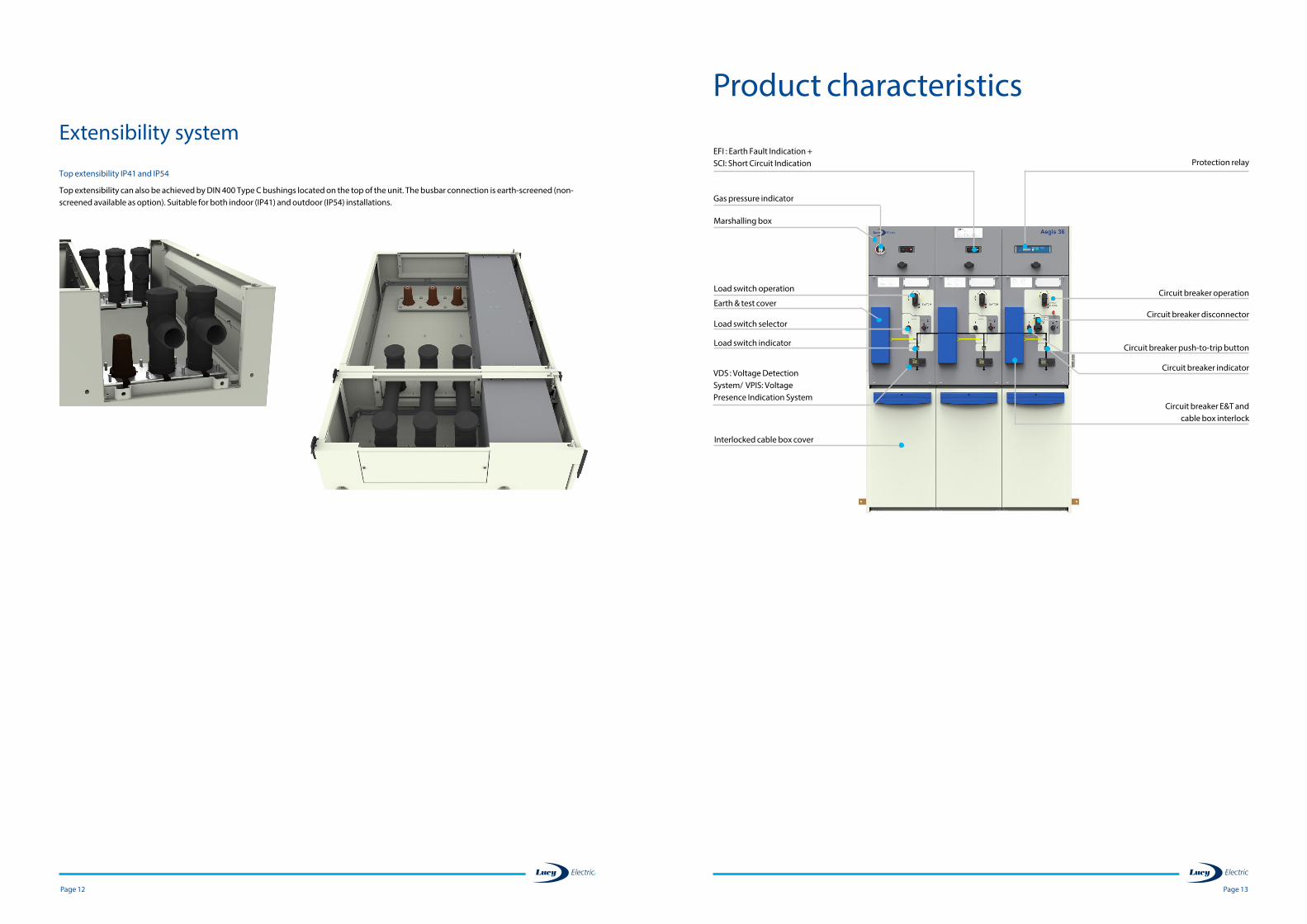
Product characteristics
Marshalling box
EFI : Earth Fault Indication + SCI: Short Circuit Indication
Gas pressure indicator
Protection relay
VDS : Voltage Detection System/ VPIS: Voltage Presence Indication System
Earth & test cover
Load switch selector
Load switch operation
Load switch indicator
Circuit breaker operation
Circuit breaker push-to-trip button
Circuit breaker disconnector
Circuit breaker E&T and cable box interlock
Circuit breaker indicator
Interlocked cable box cover
Page 15 Page 14
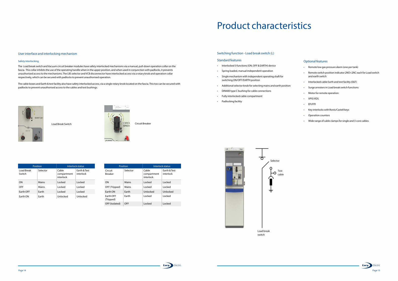
Load Break Switch Circuit Breaker
User interface and interlocking mechanism
Safety interlocking
The Load break switch and Vacuum circuit breaker modules have safety interlocked mechanisms via a manual, pull-down operation collar on the fascia. This collar inhibits the use of the operating handle when in the upper position, and when used in conjunction with padlocks, it prevents unauthorised access to the mechanisms. The LBS selector and VCB disconnector have interlocked access via a rotary knob and operation collar respectively, which can be secured with padlocks to prevent unauthorised operation.
The cable boxes and Earth & test facility also have safety interlocked access, via a single rotary knob located on the fascia. This too can be secured with padlocks to prevent unauthorised access to the cables and test bushings.
Position Interlock status
Load Break Switch
Selector Cable compartment interlock
Earth & Test interlock
ON Mains Locked Locked
OFF Mains Locked Locked
Earth OFF Earth Locked Locked
Earth ON Earth Unlocked Unlocked
Position Interlock status
Circuit Breaker
Selector Cable compartment interlock
Earth & Test interlock
ON Mains Locked Locked
OFF (Tripped) Mains Locked Locked
Earth ON Earth Unlocked Unlocked
Earth OFF (Tripped)
Earth Locked Locked
OFF (Isolated) OFF Locked Locked
Product characteristics
Standard features
• Interlocked 3 functions (ON, OFF & EARTH) device
• Spring loaded, manual independent operation
• Single mechanism with independent operating shaft for switching ON/OFF/EARTH position
• Additional selector knob for selecting mains and earth position
• DIN400 type C bushing for cable connections
• Fully interlocked cable compartment
• Padlocking facility
Switching function - Load break switch (L)
Optional features
• Remote low gas pressure alarm (one per tank)
• Remote switch position indicator 2NO+2NC each for Load switch and earth switch
• Interlocked cable Earth and test facility (E&T)
• Surge arresters in Load break switch functions
• Motor for remote operation
• VPIS/VDS
• EFI/FPI
• Key interlocks with Ronis/Castell keys
• Operation counters
• Wide range of cable clamps for single and 3-core cables
Load break switch
Test cable
Selector
Page 17 Page 16
Standard features
• Interlocked 3 functions (ON, OFF and EARTH) device
• Spring loaded, manual independent operation
• Single mechanism with an independent operating shaft for switching ON/OFF
• Additional selector shaft for selecting mains, off and earth position
• DIN400 type C bushing for cable connections
• Fully interlocked cable compartment
• Padlocking facility with 10 mm hole diameter
• Local mechanical push to trip button
Vacuum Circuit Breaker (V)
Circuit breaker
Test cable
Disconnector
Product characteristics
• Trip coil for relay tripping
Optional features
• Remote low gas pressure alarm (one per tank)
• VPIS/VDS
• Operation counters
• Interlocked cable Earth and test facility (E&T)
• Self-powered IDMT relay protection
• Key interlocks Ronis/Castell keys
• Remote switch position indicator 2NO+2NC each for vacuum breaker and earth switch
• Motor for remote operation
• Trip coils for remote tripping
• Under voltage release coil
• Secondary injection for testing protection CT operation
• Wide range of cable clamps for single and 3-core cables
Product characteristics
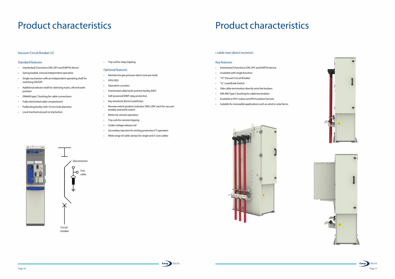
r cable riser (direct incomer)
Key features
• Interlocked 3 functions (ON, OFF and EARTH) device
• Available with single function
• “rV” Vacuum Circuit Breaker
• “rL” Load Break Switch
• Side cable termination directly onto the busbars
• DIN 400 Type C bushing for cable termination
• Available in IP41 indoor and IP54 outdoor formats
• Suitable for renewable applications such as wind or solar farms
Page 19 Page 18
Aegis 36 is fully compatible with the relays below:
Woodward Kries Fanox
WIP1 IKI-35 SIA-C SIA-B
Power
Self powered • • • •
Auxiliary powered • • • •
Dual powered • • • •
Protection
Earth fault protection • • • •
Overcurrent protection • • • •
Short circuit protection • • • •
Thermal overload protection •
Control
Circuit breaker tripping • • • •
Remote tripping • • •
Tripping indication • • • •
Fault recording • • • •
Measurements
Earth fault current • • • •
Peak demand current •
Phase current • • • •
Inputs / Outputs
Phase current inputs • • • •
Earth fault current inputs • • •
Logic inputs •
Logic relay outputs • •
RS 485 communication port • •
Protocols
Modbus • • •
Characteristics
Display • • • •
LED indicator • • •
Fault memory • • • •
Setting via buttons • • • •
Password protection • • •
Key • Feature supported Refer to manufacturer documentation
NB: Other manufacturer relays are available on request
Product characteristicsCircuit breaker protection – relays
Product characteristicsCircuit breaker protection relays
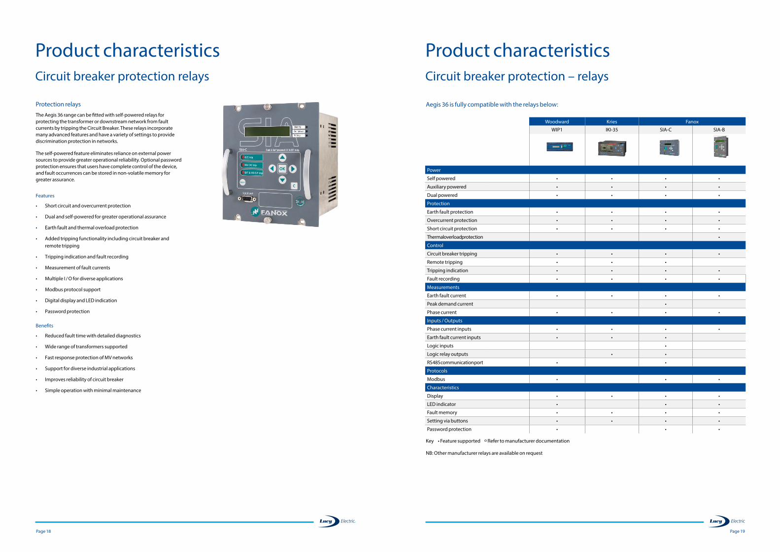
Protection relays
The Aegis 36 range can be fitted with self-powered relays for protecting the transformer or downstream network from fault currents by tripping the Circuit Breaker. These relays incorporate many advanced features and have a variety of settings to provide discrimination protection in networks.
The self-powered feature eliminates reliance on external power sources to provide greater operational reliability. Optional password protection ensures that users have complete control of the device, and fault occurrences can be stored in non-volatile memory for greater assurance.
Features
• Short circuit and overcurrent protection
• Dual and self-powered for greater operational assurance
• Earth fault and thermal overload protection
• Added tripping functionality including circuit breaker and remote tripping
• Tripping indication and fault recording
• Measurement of fault currents
• Multiple I / O for diverse applications
• Modbus protocol support
• Digital display and LED indication
• Password protection
Benefits
• Reduced fault time with detailed diagnostics
• Wide range of transformers supported
• Fast response protection of MV networks
• Support for diverse industrial applications
• Improves reliability of circuit breaker
• Simple operation with minimal maintenance
Page 21 Page 20
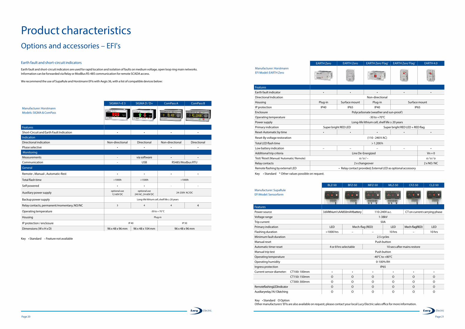
Key • Standard O Option
BLZ-50 BFZ-50 MFZ-50 MLZ-50 CFZ-50 CLZ-50
Manufacturer: SupaRuleEFI Model: Sensorform
Features
Power source 3.6V lithium ½ AA 850mAH battery 110-240V a.c. CT on current carrying phase
Voltage range 1-38kV
Trip current 50A
Primary indication LED Mech-flag (RED) LED Mech-flag (RED) LED
Flashing duration >1000 hrs – – 10 hrs – 10 hrs
Minimum fault duration 2.5 cycles
Manual reset Push button
Automatic timer reset 4 or 8 hrs selectable 10 secs after mains restore
Manual trip test Push button
Operating temperature -40°C to +80°C
Operating humidity 0-100% RH
Ingress protection IP65
Current sensor diameter: CT100: 100mm • • • • • •
CT150: 150mm O O O O O O
CT300: 300mm O O O O O O
Remote flashing LED indicator O O O O O O
Auxiliary relay, 1N / O latching O O O O O O
EARTH Zero EARTH Zero EARTH Zero ‘Flag' EARTH Zero ‘Flag' EARTH 4.0
Manufacturer: HorstmannEFI Model: EARTH Zero
Features
Earth fault indicator • • • • •
Directional Indication Non-directional
Housing Plug-in Surface mount Plug-in Surface mount
IP protection IP40 IP65 IP40 IP65
Enclosure Polycarbonate (weather and sun-proof)
Operating temperature -30 to +70°C
Power supply Long-life lithium cell, shelf life ≥ 20 years
Primary indication Super bright RED LED Super bright RED LED + RED flag
Reset-Automatic by time • • • • •
Reset-By voltage restoration (110 - 240 V AC)
Total LED flash time > 1.200 h
Low battery indication – – – – •
Additional trip criteria Line De-Energized Vn = 0
Test/ Reset (Manual/ Automatic/ Remote) o / o / – o / o / o
Relay contacts 2 x changeover 2 x NO / NC
Remote flashing by external LED • Relay contact provided, External LED as optional accessory
Key • Standard * Other values possible on request.
Other manufacturers' EFIs are also available on request, please contact your local Lucy Electric sales office for more information.
Earth fault and short-circuit indicators
Earth fault and short-circuit indicators are used for rapid location and isolation of faults on medium voltage, open loop ring main networks. Information can be forwarded via Relay or ModBus RS-485 communication for remote SCADA access.
We recommend the use of SupaRule and Horstmann EFIs with Aegis 36, with a list of compatible devices below:
Product characteristicsOptions and accessories – EFI's
SIGMA F+E 3 SIGMA D / D+ ComPass A ComPass B
Manufacturer: HorstmannModels: SIGMA & ComPass
Features
Short-Circuit and Earth Fault Indication • • • •
Indication
Directional indication Non-directional Directional Non-directional Directional
Phase selective • • • •
Monitoring
Measurements - via software • •
Communication - USB RS485/Modbus RTU
General
Remote-, Manual-, Automatic-Rest • • • •
Total flash time >1000h >1500h >1000h
Self powered • • - -
Auxiliary power supplyoptional use 12-60V DC
optional use 24V AC, 24-60V DC
24-230V AC/DC
Backup power supply Long-life lithium cell, shelf life ≥ 20 years
Relay contacts, permanent/momentary, NO/NC 3 4 4 4
Operating temperature -30 to + 70 °C
Housing Plug-in
IP protection / enclosure IP 40 IP 50
Dimensions (W x H x D) 96 x 48 x 96 mm 96 x 48 x 104 mm 96 x 48 x 96 mm
Key • Standard – Feature not available
Page 23 Page 22
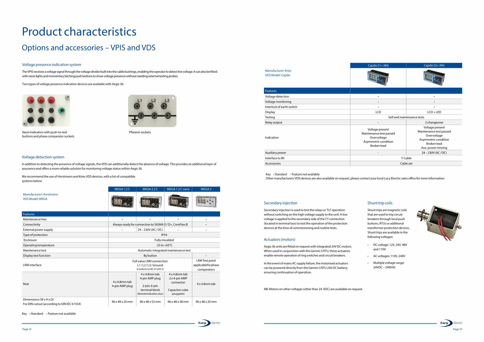
Capdis S1+ (R4) Capdis S2+ (R4)
Manufacturer: KriesVDS Model: Capdis
Features
Voltage detection • •
Voltage monitoring – •
Interlock of earth switch – •
Display LCD LCD + LED
Testing Self and maintenance tests
Relay output – 2 changeover
Indication
Voltage present Maintenance test passed
Overvoltage Asymmetric condition
Broken lead
Voltage present Maintenance test passed
Overvoltage Asymmetric condition
Broken lead Aux. power missing
Auxiliary power - 24 – 230V (AC / DC)
Interface to IKI Y-Cable
Accessories Cable set
Key • Standard – Feature not available Other manufacturers' VDS devices are also available on request, please contact your local Lucy Electric sales office for more information.
Secondary injection
Secondary injection is used to test the relays or TLF operation without switching on the high voltage supply to the unit. A low voltage is applied to the secondary side of the CT connection (located in terminal box) to test the operation of the protection devices at the time of commissioning and routine tests.
Actuators (motors)
Aegis 36 units are fitted on request with integrated 24V DC motors. When used in conjunction with the Gemini 3 RTU, these actuators enable remote operation of ring switches and circuit breakers.
In the event of mains AC supply failure, the motorised actuators can be powered directly from the Gemini 3 RTU 24V DC battery; ensuring continuation of operation.
Shunt trip coils
Shunt trips are magnetic coils that are used to trip circuit breakers through local push buttons, RTUs or additional transformer protection devices. Shunt trips are available in the following voltages:
• DC voltage: 12V, 24V, 48V and 110V
• AC voltages: 110V, 240V
• Multiple voltage range: 24VDC – 240VAC
NB: Motors on other voltages (other than 24 VDC) are available on request.
Product characteristicsOptions and accessories – VPIS and VDS
Voltage presence indication system
The VPIS receives a voltage signal through the voltage divider built into the cable bushings, enabling the operator to detect live voltage. It can also be fitted with neon lights and momentary latching push buttons to show voltage presence without needing external testing probes.
Two types of voltage presence indication devices are available with Aegis 36:
Neon indicators with push-to-test buttons and phase comparator sockets
Pfisterer sockets
Voltage detection system
In addition to detecting the presence of voltage signals, the VDS can additionally detect the absence of voltage. This provides an additional layer of assurance and offers a more reliable solution for monitoring voltage status within Aegis 36.
We recommend the use of Horstmann and Kries VDS devices, with a list of compatible systems below:
WEGA 1.2 C WEGA 2.2 C WEGA 1.2 C vario WEGA 3
Manufacturer: HorstmannVDS Model: WEGA
Features
Maintenance free • • • •
Connectivity Always ready for connection to SIGMA D / D+, ComPass B –
External power supply – 24 – 230V (AC / DC) – –
Type of protection IP54
Enclosure Fully moulded
Operating temperature -25 to +65°C
Maintenance test Automatic integrated maintenance test
Display test function By button –
LRM interfaceFull value LRM connection:
L1 / L2 / L3 / Ground(Conform to IEC 61243-5)
LRM Test point applicable for phase
comparators
Rear 4 x 4.8mm tab
4-pin AMP plug
4 x 4.8mm tab 4-pin AMP plug
2-pin, 6-pin terminal block
(Remote indication, Aux)
4 x 4.8mm tab 2 x 4-pin AMP
connector
Capacitor cube(pluggable)
4 x 4.8mm tab
Dimensions (W x H x D) For DIN cutout (according to DIN IEC 61554)
96 x 48 x 20 mm 96 x 48 x 52 mm 96 x 48 x 38 mm 96 x 48 x 20 mm
Key • Standard – Feature not available
Page 25 Page 24
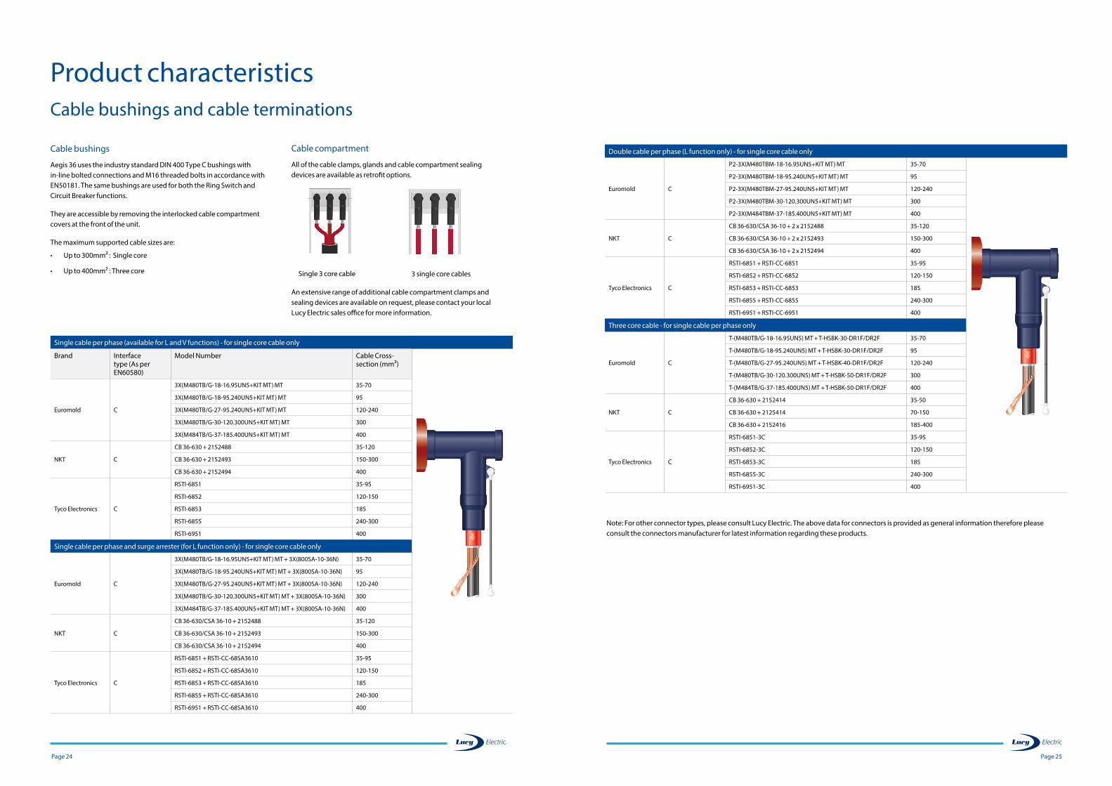
Double cable per phase (L function only) - for single core cable only
Euromold C
P2-3X(M480TBM-18-16.95UN5+KIT MT) MT 35-70
P2-3X(M480TBM-18-95.240UN5+KIT MT) MT 95
P2-3X(M480TBM-27-95.240UN5+KIT MT) MT 120-240
P2-3X(M480TBM-30-120.300UN5+KIT MT) MT 300
P2-3X(M484TBM-37-185.400UN5+KIT MT) MT 400
NKT C
CB 36-630/CSA 36-10 + 2 x 2152488 35-120
CB 36-630/CSA 36-10 + 2 x 2152493 150-300
CB 36-630/CSA 36-10 + 2 x 2152494 400
Tyco Electronics C
RSTI-6851 + RSTI-CC-6851 35-95
RSTI-6852 + RSTI-CC-6852 120-150
RSTI-6853 + RSTI-CC-6853 185
RSTI-6855 + RSTI-CC-6855 240-300
RSTI-6951 + RSTI-CC-6951 400
Three core cable - for single cable per phase only
Euromold C
T-(M480TB/G-18-16.95UN5) MT + T-HSBK-30-DR1F/DR2F 35-70
T-(M480TB/G-18-95.240UN5) MT + T-HSBK-30-DR1F/DR2F 95
T-(M480TB/G-27-95.240UN5) MT + T-HSBK-40-DR1F/DR2F 120-240
T-(M480TB/G-30-120.300UN5) MT + T-HSBK-50-DR1F/DR2F 300
T-(M484TB/G-37-185.400UN5) MT + T-HSBK-50-DR1F/DR2F 400
NKT C
CB 36-630 + 2152414 35-50
CB 36-630 + 2125414 70-150
CB 36-630 + 2152416 185-400
Tyco Electronics C
RSTI-6851-3C 35-95
RSTI-6852-3C 120-150
RSTI-6853-3C 185
RSTI-6855-3C 240-300
RSTI-6951-3C 400
Note: For other connector types, please consult Lucy Electric. The above data for connectors is provided as general information therefore please consult the connectors manufacturer for latest information regarding these products.
Product characteristicsCable bushings and cable terminations
Cable bushings
Aegis 36 uses the industry standard DIN 400 Type C bushings with in-line bolted connections and M16 threaded bolts in accordance with EN50181. The same bushings are used for both the Ring Switch and Circuit Breaker functions.
They are accessible by removing the interlocked cable compartment covers at the front of the unit.
The maximum supported cable sizes are:
• Up to 300mm² : Single core
• Up to 400mm² : Three core Single 3 core cable 3 single core cables
Cable compartment
All of the cable clamps, glands and cable compartment sealing devices are available as retrofit options.
An extensive range of additional cable compartment clamps and sealing devices are available on request, please contact your local Lucy Electric sales office for more information.
Single cable per phase (available for L and V functions) - for single core cable only
Brand Interface type (As per EN60580)
Model Number Cable Cross-section (mm²)
Euromold C
3X(M480TB/G-18-16.95UN5+KIT MT) MT 35-70
3X(M480TB/G-18-95.240UN5+KIT MT) MT 95
3X(M480TB/G-27-95.240UN5+KIT MT) MT 120-240
3X(M480TB/G-30-120.300UN5+KIT MT) MT 300
3X(M484TB/G-37-185.400UN5+KIT MT) MT 400
NKT C
CB 36-630 + 2152488 35-120
CB 36-630 + 2152493 150-300
CB 36-630 + 2152494 400
Tyco Electronics C
RSTI-6851 35-95
RSTI-6852 120-150
RSTI-6853 185
RSTI-6855 240-300
RSTI-6951 400
Single cable per phase and surge arrester (for L function only) - for single core cable only
Euromold C
3X(M480TB/G-18-16.95UN5+KIT MT) MT + 3X(800SA-10-36N) 35-70
3X(M480TB/G-18-95.240UN5+KIT MT) MT + 3X(800SA-10-36N) 95
3X(M480TB/G-27-95.240UN5+KIT MT) MT + 3X(800SA-10-36N) 120-240
3X(M480TB/G-30-120.300UN5+KIT MT) MT + 3X(800SA-10-36N) 300
3X(M484TB/G-37-185.400UN5+KIT MT) MT + 3X(800SA-10-36N) 400
NKT C
CB 36-630/CSA 36-10 + 2152488 35-120
CB 36-630/CSA 36-10 + 2152493 150-300
CB 36-630/CSA 36-10 + 2152494 400
Tyco Electronics C
RSTI-6851 + RSTI-CC-68SA3610 35-95
RSTI-6852 + RSTI-CC-68SA3610 120-150
RSTI-6853 + RSTI-CC-68SA3610 185
RSTI-6855 + RSTI-CC-68SA3610 240-300
RSTI-6951 + RSTI-CC-68SA3610 400
Page 27 Page 26
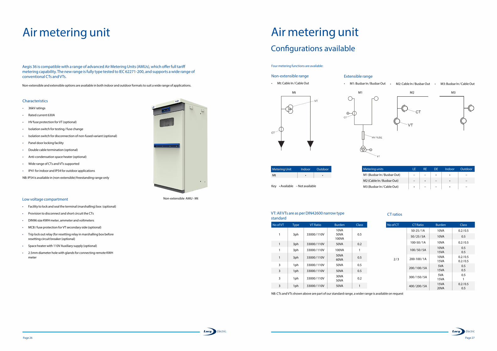
Four metering functions are available:
Non-extensible range
• Mt: Cable In / Cable Out
Air metering unitConfigurations available
Metering Unit Indoor Outdoor
Mt • •
Extensible range
• M1: Busbar In / Busbar Out • M2: Cable In / Busbar Out • M3: Busbar In / Cable Out
Metering units LE RE DE Indoor Outdoor
M1 (Busbar In / Busbar Out) – – • • –
M2 (Cable In / Busbar Out) – • – • –
M3 (Busbar In / Cable Out) • – – • –Key • Available – Not available
CT ratios
No of CT CT Ratio Burden Class
2 / 3
50-25 / 1A 10VA 0.2 / 0.5
50 / 25 / 5A 10VA 0.5
100-50 / 1A 10VA 0.2 / 0.5
100 / 50 / 5A 10VA 15VA
0.5 0.5
200-100 / 1A10VA 15VA
0.2 / 0.5 0.2 / 0.5
200 / 100 / 5A 5VA
15VA0.5 0.5
300 / 150 / 5A5VA
15VA0.5 1
400 / 200 / 5A15VA 20VA
0.2 / 0.5 0.5
No of VT Type VT Ratio Burden Class
1 3ph 33000 / 110V10VA 50VA
100VA0.5
1 3ph 33000 / 110V 50VA 0.2
1 3ph 33000 / 110V 100VA 1
1 3ph 33000 / 110V50VA 60VA
0.5
3 1ph 33000 / 110V 50VA 0.5
3 1ph 33000 / 110V 50VA 0.5
3 1ph 33000 / 110V30VA 50VA
0.2
3 1ph 33000 / 110V 50VA 1
NB: CTs and VTs shown above are part of our standard range, a wider range is available on request
Mt M1 M2 M3
VT: All VTs are as per DIN42600 narrow type standard
Aegis 36 is compatible with a range of advanced Air Metering Units (AMUs), which offer full tariff metering capability. The new range is fully type tested to IEC 62271-200, and supports a wide range of conventional CTs and VTs. Non-extensible and extensible options are available in both indoor and outdoor formats to suit a wide range of applications.
Air metering unit
Low voltage compartment
• Facility to lock and seal the terminal (marshalling) box (optional)
• Provision to disconnect and short circuit the CTs
• DIN96 size KWH meter, ammeter and voltmeters
• MCB / fuse protection for VT secondary side (optional)
• Trip lock out relay (for resetting relay in marshalling box before resetting circuit breaker (optional)
• Space heater with 110V Auxiliary supply (optional)
• 2.5mm diameter hole with glands for connecting remote KWH meter
Characteristics
• 36kV ratings
• Rated current 630A
• HV fuse protection for VT (optional)
• Isolation switch for testing / fuse change
• Isolation switch for disconnection of non-fused variant (optional)
• Panel door locking facility
• Double cable termination (optional)
• Anti-condensation space heater (optional)
• Wide range of CTs and VTs supported
• IP41 for indoor and IP54 for outdoor applications
NB: IP54 is available in (non-extensible) freestanding range only
Non-extensible AMU - Mt
Page 29 Page 28
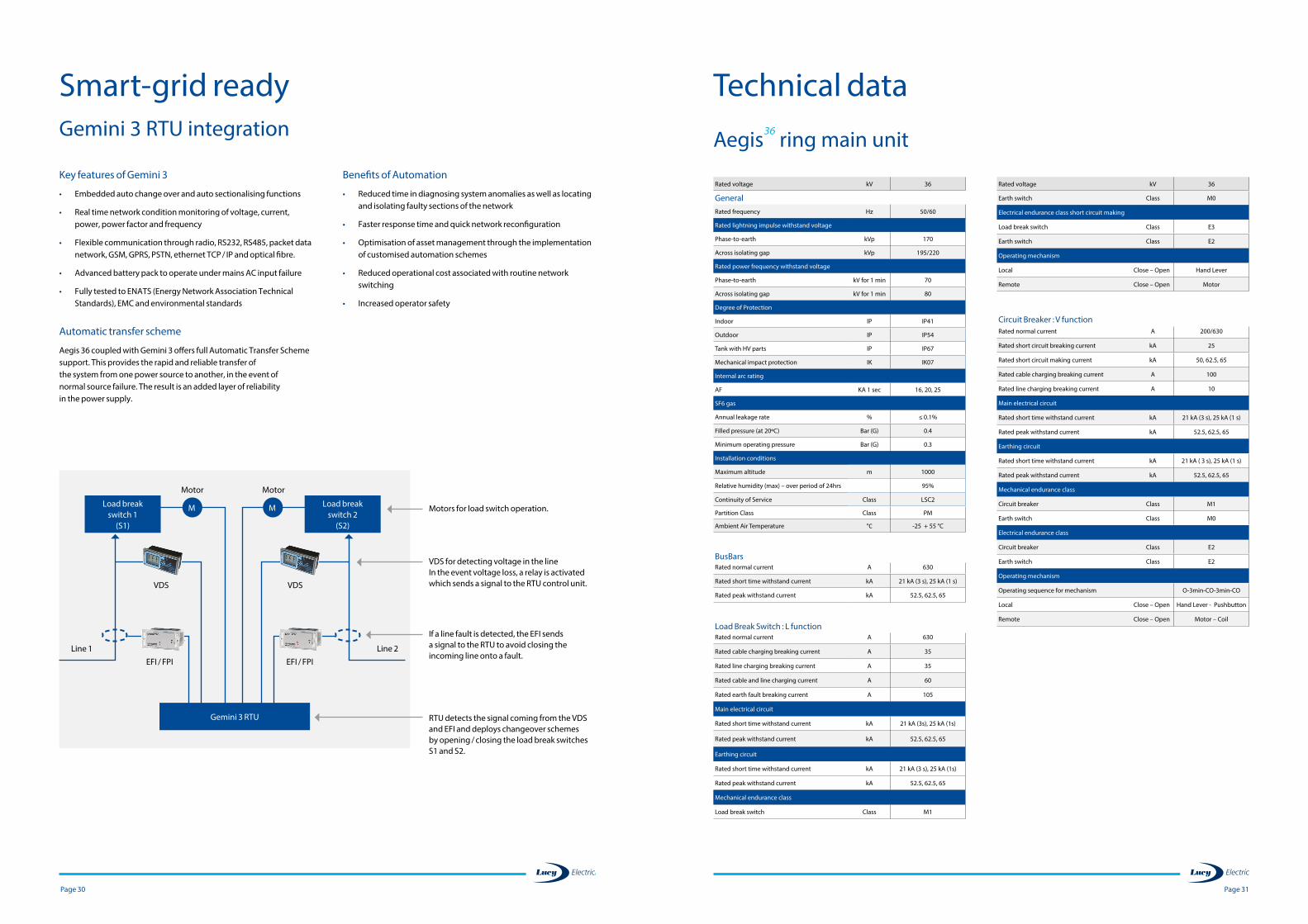
Aegis 36 can be configured with the next- generation Gemini 3 RTU. This is an all new, highly flexible, general-purpose Remote Terminal Unit designed to remotely monitor and control medium and high voltage switchgear.
The Gemini 3 has a modular design such that it can be configured from a simple monitoring only device to a fully functional automated switch controller. It has the ability to transition from a basic to an advanced RTU by plugging in additional modules. These modules are rugged, making the device field serviceable and future proof.
The Gemini 3 modules available are:
Master Control Module (MCM) – This contains the main processor and supervises all modules. The MCM handles the protocol commu-nications.
Single Switch Module (SSM) – This provides the inputs and outputs to perform secure interlocked control of a single gas enclosed switch.
Dual Switch Module (DSM) – This provides the inputs and outputs to perform secure interlocked control of two MV ring switches.
Power Supply Module (PSM) – This module works with the switch control modules to provide secure switching operations. The PSM generates regulated power to all other modules and external com-munication equipment. The PSM also provides the intelligent battery charging function to maintain a secure supply.
Input Output Module (IOM) – This is a general purpose module that covers digital and analogue inputs and relay outputs.
Fault Passage Module (FPM) – This is a dual fault passage indicator module which detects and alarms for Overcurrent and Earth Faults.
Human to Machine Interface (HMI) – This is an optional module that allows local control and monitoring without the need for a Com-puter. It allows local controls to be issued by an authorised Engineer (security enabled) or just provide data to be viewed locally.
Characteristics
• Fault detection (Earth and Phase)
• LED status indicators
• Real time clock (SCADA synchronised)
• Dual isolated Ethernet and RS232 ports
• Isolated RS485 port
• Supervisory selection and indication
• Event memory – 7000 events in non-volatile memory
• Communication protocol
- DNP 3.0 TCP/IP or Serial
- IEC 60870-5-101
- IEC 60870-5-104
- Modbus TCP or RTU
• Maintenance free
Smart-grid readyGemini 3 RTU integration
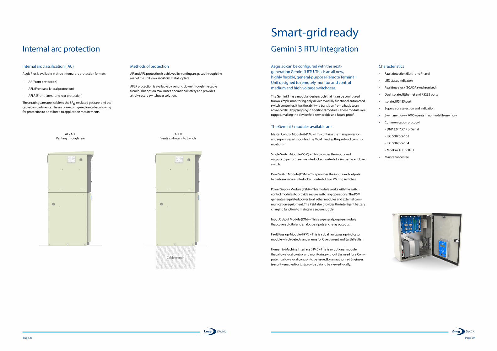
Internal arc classification (IAC)
Aegis Plus is available in three internal arc protection formats:
• AF (Front protection)
• AFL (Front and lateral protection)
• AFLR (Front, lateral and rear protection)
These ratings are applicable to the SF6 insulated gas tank and the cable compartments. The units are configured on order, allowing for protection to be tailored to application requirements.
Methods of protection
AF and AFL protection is achieved by venting arc gases through the rear of the unit via a sacrificial metallic plate.
AFLR protection is available by venting down through the cable trench. This option maximises operational safety and provides a truly secure switchgear solution.
Internal arc protection
AF / AFLVenting through rear
AFLR Venting down into trench
Cable trench
Page 31 Page 30
Technical data
Aegis36 ring main unit
Rated voltage kV 36
GeneralRated frequency Hz 50/60
Rated lightning impulse withstand voltage
Phase-to-earth kVp 170
Across isolating gap kVp 195/220
Rated power frequency withstand voltage
Phase-to-earth kV for 1 min 70
Across isolating gap kV for 1 min 80
Degree of Protection
Indoor IP IP41
Outdoor IP IP54
Tank with HV parts IP IP67
Mechanical impact protection IK IK07
Internal arc rating
AF KA 1 sec 16, 20, 25
SF6 gas
Annual leakage rate % ≤ 0.1%
Filled pressure (at 20ºC) Bar (G) 0.4
Minimum operating pressure Bar (G) 0.3
Installation conditions
Maximum altitude m 1000
Relative humidity (max) – over period of 24hrs 95%
Continuity of Service Class LSC2
Partition Class Class PM
Ambient Air Temperature °C -25 + 55 °C
BusBarsRated normal current A 630
Rated short time withstand current kA 21 kA (3 s), 25 kA (1 s)
Rated peak withstand current kA 52.5, 62.5, 65
Load Break Switch : L functionRated normal current A 630
Rated cable charging breaking current A 35
Rated line charging breaking current A 35
Rated cable and line charging current A 60
Rated earth fault breaking current A 105
Main electrical circuit
Rated short time withstand current kA 21 kA (3s), 25 kA (1s)
Rated peak withstand current kA 52.5, 62.5, 65
Earthing circuit
Rated short time withstand current kA 21 kA (3 s), 25 kA (1s)
Rated peak withstand current kA 52.5, 62.5, 65
Mechanical endurance class
Load break switch Class M1
Rated voltage kV 36
Earth switch Class M0
Electrical endurance class short circuit making
Load break switch Class E3
Earth switch Class E2
Operating mechanism
Local Close – Open Hand Lever
Remote Close – Open Motor
Circuit Breaker : V function Rated normal current A 200/630
Rated short circuit breaking current kA 25
Rated short circuit making current kA 50, 62.5, 65
Rated cable charging breaking current A 100
Rated line charging breaking current A 10
Main electrical circuit
Rated short time withstand current kA 21 kA (3 s), 25 kA (1 s)
Rated peak withstand current kA 52.5, 62.5, 65
Earthing circuit
Rated short time withstand current kA 21 kA ( 3 s), 25 kA (1 s)
Rated peak withstand current kA 52.5, 62.5, 65
Mechanical endurance class
Circuit breaker Class M1
Earth switch Class M0
Electrical endurance class
Circuit breaker Class E2
Earth switch Class E2
Operating mechanism
Operating sequence for mechanism O-3min-CO-3min-CO
Local Close – Open Hand Lever - Pushbutton
Remote Close – Open Motor – Coil
Key features of Gemini 3
• Embedded auto change over and auto sectionalising functions
• Real time network condition monitoring of voltage, current, power, power factor and frequency
• Flexible communication through radio, RS232, RS485, packet data network, GSM, GPRS, PSTN, ethernet TCP / IP and optical fibre.
• Advanced battery pack to operate under mains AC input failure
• Fully tested to ENATS (Energy Network Association Technical Standards), EMC and environmental standards
Automatic transfer scheme
Aegis 36 coupled with Gemini 3 offers full Automatic Transfer Scheme support. This provides the rapid and reliable transfer of the system from one power source to another, in the event of normal source failure. The result is an added layer of reliability in the power supply.
Benefits of Automation
• Reduced time in diagnosing system anomalies as well as locating and isolating faulty sections of the network
• Faster response time and quick network reconfiguration
• Optimisation of asset management through the implementation of customised automation schemes
• Reduced operational cost associated with routine network switching
• Increased operator safety
Smart-grid readyGemini 3 RTU integration
Motors for load switch operation.
VDS for detecting voltage in the lineIn the event voltage loss, a relay is activated which sends a signal to the RTU control unit.
If a line fault is detected, the EFI sends a signal to the RTU to avoid closing the incoming line onto a fault.
RTU detects the signal coming from the VDS and EFI and deploys changeover schemes by opening / closing the load break switches S1 and S2.
M M
Motor Motor
VDS
EFI / FPI EFI / FPI
Line 1
VDS
Line 2
Load break switch 1
(S1)
Load break switch 2
(S2)
Gemini 3 RTU
Page 33
Motor wiring only (required for future motorisation)
Motor with wiring (tick for each selected function, if needed)
Cable Earth & Test facility (E&T) (tick for each selected function, if needed)
Cable compartment
Cable clamp material (choose any one) Metal
Plastic
Cable entry type (choose any one) Single core cable
3 core cable
Cable cross section
Internal arc
Gas enclosure
Cable box
Internal arc classification
Rear vent AF
AFL
Bottom venting into cable trench – AFLR
Auxiliary switches (choose any one) 1N/O, 1N/C
2N/O, 2N/C
First Second Third Fourth
Company:
Tel no:
Email:
Order number:
Name:
Address:
Aegis36 order formTo use this form, please fill in the appropriate sections and return the completed form to your nearest Lucy Electric sales office
Type of function 36 kV
L – LBS 630 A
V – VCB 630 A
Functions required:
IP rating: Installation conditions (choose any one) IP54 Metal clad outdoor (available for non extensible range only)
IP41 Indoor (available for extensible and non extensible range)
Order quantity / number of units (please fill separate form for each type)
Extensibility (choose any one) Non extensible
Top extensible left hand right hand both sides
Voltage indication
VPIS (choose one) Neon indicator with push to test button
Horstmann Wega 1.2
Page 32
1210 mm 1610 mm 870 mm
3-function unit 4-function unit
H
H
653
mm
1690
mm
Dimensions
Side view
Non-extensible
Page 35
*Please add any additional details in the comment section below.
Comments
Optional features applicable to L (Load break switch) function only
EFI (choose any one) Sensorform BFZ-50
MFZ-50
MLZ-50
CFZ-50
CLZ-50
BLZ-50
Optional features applicable to V or T (Vacuum Circuit Breaker) function only
Secondary injection (tick for each function, if needed)
Protection device (choose any one)
Ashida ADR241S Relay
Kries IKI-35 Relay
Fanox SIA-C Relay Protection CT for Relay (choose any one)
Dual (Primary) Ratio CT 100:50 / -
Dual (Primary) Ratio CT 200:100 / -
Shunt trips (choose any one) 12V DC
24V DC
48V DC
110V DC
110V AC
240V AC
Multiple voltage (24V DC – 240V AC / DC)
Page 34
CT Ratio Burden and Class Mounting type
600 - 200/1A2.5 VA, CL-5P10 Bushing mounted
5 VA, CL-5P20 Cable mounted
400-200/1A2.5 VA, CL-5P10 Bushing mounted
5 VA , CL-5P20 Cable mounted
200-100/1A2.5 VA, CL-5P10 Bushing mounted
5 VA, CL-5P20 Cable mounted
100-50/1A2.5 VA, CL-5P10 Bushing mounted
5 VA, CL-5P20 Cable mounted

DisclaimerLucy Electric has a policy of continuous research and development and accordingly reserves the right to change the design and specification of its products without prior notice.
LEAEG360419
engineering intelligent solutions
www.lucyelectric.com
Lucy Electric worldwide offices
Lucy Electric Ltd.Howland Road, Thame, Oxfordshire,OX9 3UJ, United Kingdom Tel: +44 1844 267 267 GeneralTel: +44 1844 267 222 SalesFax: +44 1844 267 223 Email: [email protected]
Lucy Middle East FZE.PO Box 17335, Jebel Ali, Dubai, United Arab Emirates Tel: +97 148 129 999Fax: +97 148 129 900 Email: [email protected]
Lucy Electric (Thailand) Ltd.388 Exchange Tower, 37th Flr Unit 3702,Sukhumvit Road, Klongtoey Sub district, Klongtoey District, Bangkok, 10110, ThailandTel: +66 (02) 663 4290 Fax: +66 (02) 663 4293Email: [email protected]
Lucy Switchgear Arabia Co. Ltd.Novotel Business Centre,P.O. Box 35340, Dammam 31488,Saudi ArabiaTel: +966 138 147 910Fax: +966 138 147 914Email: [email protected]
Lucy Electric (South Africa).Unit 12 & 13, Block C, Honeydew Business Park,1503 Citrus Street, Laser Park, Honeydew, 2170, South AfricaTel: +27 11 025 7490Fax: +27 11 794 3277Email: [email protected]
Postal Address:P.O. Box 1078, Honeydew, 2040
Lucy Asia Pacific Sdn Bhd.L17-05-06, PJX-HM Shah Tower,No16A Jalan Persiaran Barat,46050 Petaling Jaya, Selangor, Malaysia Tel: +603 74910700Fax: +603 79316923Email: [email protected]
Lucy Electric India Private LtdF-10, MIDC, AmbadNasik 422010IndiaTel: +91 253 2381603Fax: +91 253 2381247Email: [email protected]
Lucy Equipamentos Elétricos Ltda.Av. das Araucárias 2558 Thomaz Coelho, CEP 83707-067, Araucária Paraná State, BrazilTel: +55 (41) 2106 2801Email: [email protected]


![AEGIS: A Fast Authenticated Encryption Algorithm …2013 [31]. AEGIS-128L is introduced into this submission. 4 Chapter 2 Speci cation The speci cation of AEGIS-128, AEGIS-256 and](https://img.pdfslide.us/doc/110x75/5f06a2a57e708231d418f98b/aegis-a-fast-authenticated-encryption-algorithm-2013-31-aegis-128l-is-introduced.jpg)