Embed Size (px)
Citation preview

MDSC-2224
User Guide
(451920611391)K59030310021012014
Barco nvPresident Kennedypark 35 8500 Kortrijk BelgiumPhone +32 56233211Fax +32 56262262Support wwwbarcocomesupportVisit us at the web wwwbarcocom
Printed in Belgium
Table of contents
TABLE OF CONTENTS
1 Welcome 311 About the product 312 Whatrsquos in the box 313 About this user guide 4
2 Parts controls and connectors 521 Front view 522 Rear view 623 Connector view 6
231 MDSC-2224 LED version 6232 MDSC-2224 MNA version 7
24 Connector pin assignments 8241 Input power connector 8242 DVIndash1 connector 8243 DVI out connector 9244 RS232 connector 10245 USB connector 10246 Mini USB connector 11247 DisplayPort connector 11248 S-Video and S-Video-out connector 12
3 Display installation 1331 VESA mount installation 1332 Cover removal 1433 Video input connection 14
331 MDSC-2224 LED version 14332 MDSC-2224 MNA version 15
34 Video output connection 16341 MDSC-2224 LED version 16342 MDSC-2224 MNA version 16
35 Nexxis OR 1736 Power supply connection 1737 Cable routing 18
4 Daily operation 2141 Keyboard activationdeactivation 2142 Keyboard backlight 2243 OnOff switching 2244 Power led status 2345 OSD menu activation 2346 OSD menu navigation 2347 Shortkey functions 24
471 Main source selection 25472 Multi-image configuration 25473 Zoom factor selection 26474 Brightness adjustment 26
48 Extended keyboard functions 26481 Main source selection 27482 Second source selection 28483 Multi-image configuration 28484 Common Functions Transfer function selection 29485 Common Functions Image size selection 29486 Common Functions Zoom factor selection 30
49 Menu lockingunlocking 30
5 Advanced operation 3151 OSD picture menu 31
511 Profile 31
(451920611391)K5903031 MDSC-2224 21012014 1
Table of contents
512 Brightness 31513 Contrast 32514 Saturation 32515 Color temperature 32516 Gamma 33517 Sharpness 33
52 Picture Advanced menu 34521 Black Level 34522 Smart Video 34523 Image Position 35524 Auto Adjustment 35525 Phase 35526 ClockLine 36
53 Display Format menu 36531 Main Source (Primary Source) 36532 Component Mode 37533 Zoom 37534 Image Size 38535 2nd Picture Mode 38536 2nd Picture Source 39537 2nd Picture Position 39538 Picture Swap 40
54 Configuration menu 40541 Information 40542 Language 41543 Failover mode 41544 Extended keyboard 42545 OSD setting 42
5451 OSD Horizontal Position 425452 OSD Vertical Position 425453 OSD Time-out 43
546 Recall Profile 43547 Save Profile 43
55 System menu 44551 Power on DVI 1 44552 Power on DVI 2 44553 DVI Output 45554 Keyboard lock 45555 Keyboard backlight 45556 Power Saving 46
6 Important information 4761 Safety information 4762 Environmental information 4963 Biological hazard and returns 5164 Regulatory compliance information 5265 Cleaning and disinfection 5366 Explanation of symbols 5367 Legal disclaimer 5468 Technical specifications 5569 Open source license information 59
2 (451920611391)K5903031 MDSC-2224 21012014
1 Welcome
1 WELCOME
11 About the product
OverviewBarcorsquos MDSC-2224 is a 24-inch surgical display Purpose-built for the operating room the MDSC-2224offers an easy-clean design smart mechanics and the most detailed images in the operating room today
Ease of mindPerfect hand-eye coordination The displayrsquos high brightness high contrast and full HD resolution providesurgeons with excellent depth perception and the most accurate images The MDSC-2224 presents im-ages with unrivaled color and grayscale accuracy and with near-zero latency making it perfectly suitedfor use with todayrsquos state-of-the-art endoscopy camera systems
Multi-source multi-display imaging With its broad input connectivity the MDSC-2224 also offers flexiblemulti-modality imaging (PiP amp PaP) in new integrated operating rooms Thanks to its high-bright LEDbacklight the surgical display also ensures a long lifetime and low power consumption
Ease of installationThe MDSC-2224 comes with a smart cable management system that hides the cables for a clutter-freeset-up Its lightweight design allows easy mounting on surgical booms and spring arms Available indifferent models this surgical display also features a host of connectivity options and remote control
Ease of useBarcorsquos MDSC-2224 allows easy cleaning and complete disinfection thanks to its smooth surface sealedhousing and protective screen cover The fanless design avoids the spread of contaminants
Features
bull 24-inch wide-screen LCD with full HD resolution and 10ndashbit per color
bull Wide viewing angle
bull High-brightness LED backlightbull Advanced full 10-bit image processing algorithms with 12ndashbit LUT
bull Widest range of SD and HD input signals including 3G-SDI and DisplayPortbull Light weight to easily mount onto a boom
Innovative features are also available to give maximum flexibility when installing the display as Config-urable DVI-out and Failover Mode
12 Whatrsquos in the boxOverviewYour MDSC-2224 display comes with
bull MDSC-2224 user guide
bull DVI cable
bull AC power cordsbull external power supply
bull 4 screws and Allen key
(451920611391)K5903031 MDSC-2224 21012014 3
1 Welcome
Keep your original packaging It is designed for this display and is the ideal protectionduring transport
The user guide is available in other languages on wwwbarcocom
13 About this user guide
OverviewThis manual provides a support to the user during the installation set up and utilization of the MDSC-2224display Depending on the specific version that has been purchased some of the features and optionsdescribed in this document may not apply to the display in userrsquos hands
4 (451920611391)K5903031 MDSC-2224 21012014
2 Parts controls and connectors
2 PARTS CONTROLS ANDCONNECTORS
21 Front viewOverview
1 2 3 4 5 6 7
Image 2-1
1 Input Selection key
2 Multi-image selection key Down key
3 Image zoom key Up key
4 OSD Menu key Enter key
5 Brightness decrease Left key
6 Brightness increase Right key
7 Stand-by key
A 7-key capacitive keypad is located on the front of the display By default only the stand-by key is visible
For keyboard activation please refer to Keyboard activationdeactivation page 21
(451920611391)K5903031 MDSC-2224 21012014 5
2 Parts controls and connectors
22 Rear viewOverview
4
1
5
1
1 1
3
2
5
Image 2-2
1 VESA mount screw holes
2 Cable routing channel
3 Cable routing channel expansion clip
4 Connector compartment cover
5 Connector compartment cover fixation screws
23 Connector view
231 MDSC-2224 LED version
Overview
1 2 3 4 7 11 12 13 15
865 9 10 14
16
Image 2-3
1 RS232
2 Input power connector
3 DVI out
4 DVI-1 (digital amp analog ndash HDMI video support with HDCP)
5 SDI-1 out
6 SDI-1
7 DisplayPort (VESA std 11a)
8 Sync
9 CVBS
6 (451920611391)K5903031 MDSC-2224 21012014
2 Parts controls and connectors
10 CVBS out
11 RPr
12 GY
13 BPb
14 S-Video out
15 S-Video
16 Service
232 MDSC-2224 MNA version
Overview
1 2 4 6 7 8 9 10 11 15 16 17 19
125 13 14 18
20
3
Image 2-4
1 Optical 10Gb Ethernet SFP+ interface
2 LED2
Orange blinking Activity = (Tx) or (Rx)
Off No network activity3 LED1
Green Link is active
Off No active network connection4 LED3
Green Power on normal operation
Off System not powered
Orange blinking Error5 Micro USB interface
6 USB 20 type A interface
7 RS232
8 Input power connector
9 DVI out
10 DVI-1 (digital amp analog ndash HDMI video support with HDCP)
11 DisplayPort (VESA std 11a)
12 Sync
13 CVBS
14 CVBS out
15 RPr
16 GY
17 BPb
18 S-Video out
19 S-Video
20 Service
(451920611391)K5903031 MDSC-2224 21012014 7
2 Parts controls and connectors
() Nexxis OR functionality for more detailed information on Barcorsquos Nexxis integrated OR solution pleaserefer to the dedicated user guides Please visit mybarcocom to obtain these user guides
24 Connector pin assignments
241 Input power connector
Overview
Image 2-5
Pin Function
1 GND
2 Not connected
3 +24 VDC
4 GND
5 Shield
6 +24 VDC
The ground and the shield connections on the power input connector have no Protec-tive Earth function A Protective Earth connection is provided via a dedicated pin (seeimage 3-8)
242 DVIndash1 connector
Overview
Image 2-6
Pin Function
1 D2_Rx- (TMDS)
2 D2_Rx+ (TMDS)
3 GND (data 2 shield)
4 Not connected
5 Not connected
6 SCL (for DDC)
7 SDA (for DDC)
8 Analog vertical sync
9 D1_Rx- (TMDS)
10 D1_Rx+ (TMDS)
11 GND (data 1 shield)
8 (451920611391)K5903031 MDSC-2224 21012014
2 Parts controls and connectors
12 Not connected
13 Not connected
14 +5V input (DDC supply) ()
15 GND (cable sense)
16 Hot plug detect ()
17 D0_Rx- (TMDS)
18 D0_Rx+ (TMDS)
19 GND (data 0 shield)
20 Not connected
21 Not connected
22 GND (clock shield)
23 CK_Rx+ (TMDS)
24 CK_Rx- (TMDS)
C1 Analog Red
C2 Analog Green
C3 Analog Blue
C4 Analog horizontal sync
C5 Analog GND return (analog R G B)
() +5 VDC output selectable on either pin 14 or 16 via the OSD menu (+5V plusmn 10 500mA (max))
243 DVI out connector
Overview
Image 2-7
Pin Function
1 D2_Rx- (TMDS)
2 D2_Rx+ (TMDS)
3 GND (data 2 shield)
4 Not connected
5 Not connected
6 SCL (for DDC)
7 SDA (for DDC)
8 Not connected
9 D1_Rx- (TMDS)
10 D1_Rx+ (TMDS)
11 GND (data 1 shield)
12 Not connected
13 Not connected
14 +5V output ()
15 GND (cable sense)
16 Hot plug detect
17 D0_Rx- (TMDS)
(451920611391)K5903031 MDSC-2224 21012014 9
2 Parts controls and connectors
18 D0_Rx+ (TMDS)
19 GND (data 0 shield)
20 Not connected
21 Not connected
22 GND (clock shield)
23 CK_Rx+ (TMDS)
24 CK_Rx- (TMDS)
() +5 VDC output always available (+5V plusmn 10 500mA (max))
244 RS232 connector
Overview
Image 2-8
Pin Function
1 Not connected
2 Rx (driven by host)
3 Tx (driven by display)
4 Not connected
5 Ground
6 Not connected
7 Not connected
8 Not connected
9 Not connected
245 USB connector
Overview
Image 2-9
Pin Function
1 +5 VDC
2 Data mdash
3 Data +
4 GND
10 (451920611391)K5903031 MDSC-2224 21012014
2 Parts controls and connectors
246 Mini USB connector
Overview
12345
Image 2-10
Pin Function
1 +5 VDC
2 Data mdash
3 Data +
X Not connected
4 GND
247 DisplayPort connector
Overview
19 17 15 13 11 9 7 5 3 1
20 18 16 14 12 10 8 6 4 2
Image 2-11
Pin Function
1 ML_Lane 0 (p)
2 GND
3 ML_Lane 0 (n)
4 ML_Lane 1 (p)
5 GND
6 ML_Lane 1 (n)
7 ML_Lane 2 (p)
8 GND
9 ML_Lane 2 (n)
10 ML_Lane 3 (p)
11 GND
12 ML_Lane 3 (n)
13 CONFIG1
14 CONFIG2
15 AUX CH (p)
16 GND
17 AUX CH (n)
18 Hot Plug
19 Return
20 DP_PWR (+33 VDC)
(451920611391)K5903031 MDSC-2224 21012014 11
2 Parts controls and connectors
248 S-Video and S-Video-out connector
Overview
Image 2-12
Pin Function
1 Ground (Y)
2 Ground (C)
3 Luminance (Y)
4 Chroma (C)
SG Shielded Ground
12 (451920611391)K5903031 MDSC-2224 21012014
3 Display installation
3 DISPLAY INSTALLATION
31 VESA mount installationOverviewThe display supports mounting arm amp stands according to the VESA 100 mm standard
CAUTION Use an arm that is approved by VESA
CAUTION Use an arm that can support a weight of least 10 kg (2205 lbs)
The monitor VESA interface has been designed for a safety factor 6 (to support 6 timesthe monitor weight) In the medical system use an arm with suitable safety factor(IEC60601ndash1)
To mount the display to an arm stand1 Attach the arm stand firmly to the panel using the included 4 hexagonal screws (M4 x 25 mm) and the
dented washers Use the included Allen key to fix the screws
Image 3-1
CAUTION The 4 screws included with this display (M4 x 25 mm) can be used for anexternal VESA arm interface with a thickness of up to 5mm
If due to the thickness of the external VESA arm interface (=V) the length of the providedscrews (=L) is not suitable consider the following rule
Lmin = V + 20mm
Lmax = V + 30mm
(451920611391)K5903031 MDSC-2224 21012014 13
3 Display installation
32 Cover removalTo remove the connector compartment cover1 Loosen the screws fixing the connector compartment cover
2 Slide the cover downwards to remove it from the display
1
2 2
1
Image 3-2
33 Video input connection
About video input connectionsThe MDSC-2224 can have multiple different video inputs connected (depending on the display version)Switching between the different inputs can be easily done by pressing the direct access key for this Seethe dedicated section for more info
Futhermore if more than one video source is connected the Picture in Picture (PiP) and Side-by-Side(SbS) functionality becomes available allowing you to view two different video inputs at once Pleaserefer to the dedicated chapter for more info on how to activate and use the PiP and SbS features on yourMDSC-2224
This chapter describes how to connect the different video input types for each version of the MDSC-2224
331 MDSC-2224 LED version
To connect the video inputs1 Connect one or more of the available video source(s) to the corresponding video inputs using the ap-
propriate video cable(s)
4 5 6 7 8
1 2 3
9
Image 3-3
DVI or VGA () 4
DisplayPort 5
14 (451920611391)K5903031 MDSC-2224 21012014
3 Display installation
SDI 1
RGBS 6 7 8 2
RGB (SOG) 6 7 8
YPbPr 7 8 6
CVBS 3
S-Video 9
() PC analog (VGA) input source can be connected to the DVI-I input connector using a DVI-I to VGAadapter The use of an adapter cable of at least 015 m long will allow an easy placement inside the cablecover
332 MDSC-2224 MNA version
To connect the video inputs1 Connect one or more of the available video source(s) to the corresponding video inputs using the ap-
propriate video cable(s)
4 5 6 7 8
1 2
93
Image 3-4
Nexxis 3
DVI or VGA () 4
DisplayPort 5
RGBS 6 7 8 1
YPbPr 7 8 6
CVBS 2
S-Video 9
() PC analog (VGA) input source can be connected to the DVI-I input connector using a DVI-I to VGAadapter The use of an adapter cable of at least 015 m long will allow an easy placement inside the cablecover
(451920611391)K5903031 MDSC-2224 21012014 15
3 Display installation
34 Video output connection
About video output connectionsBeside the video input connections the MDSC-2224 also has video output capabilities allowing you toloop-through certain video inputs connected with the MDSC-2224 to another display projector videorecorder
This chapter describes how to make use of the video output connections available for each version of theMDSC-2224
341 MDSC-2224 LED version
To connect the video outputs1 Connect one or more of the available video sink(s) to the corresponding video outputs using the appro-
priate video cable(s)
4
1 2 3
Image 3-5
SDI 1
CVBS 2
S-Video 3
DVI 4 (to be configured in OSD menu)
342 MDSC-2224 MNA version
To connect the video outputs1 Connect one or more of the available video sink(s) to the corresponding video outputs using the appro-
priate video cable(s)
16 (451920611391)K5903031 MDSC-2224 21012014
3 Display installation
3
1 2
Image 3-6
CVBS 1
S-Video 2
DVI 3 (to be configured in OSD menu)Nexxis 3 (to be configured in OSD menu)
35 Nexxis OROverviewConnecting your MDSC-2224 to Barcorsquos Nexxis OR system allows you to distribute video graphics audioand computer data over the IP network in raw uncompressed format inside the operating room and evenbetween surgical suites
To connect your MDSC-2224 to Barcorsquos Nexxis OR system connect the 10Gb Ethernet interface to yourNexxis switch More info about Nexxis OR and how to configure the MDSC-2224 in your network is avail-able in the dedicated user guides Please visit wwwbarcocom to obtain these user guides
Nexxis OR is only available on the MDSC-2224 MNA version
36 Power supply connection
To connect the power supply1 Connect the supplied external DC power supply unit to the +24 VDC power input of your MDSC-2224
display
2 Plug the other end of the external DC power supply into a grounded power outlet by means of theproper power cord delivered in the packagingNote The ground and the shield connections on the power input connector have no Protective Earth
function A Protective Earth connection is provided via a dedicated pin (see image 3-8)
(451920611391)K5903031 MDSC-2224 21012014 17
3 Display installation
Image 3-7
Protective earth pin1 Earth the MDSC-2224 by connecting the protective earth pin to a grounded outlet by means of an
AWG18 (max 6ft 18m long) wire
1
Image 3-8
37 Cable routing
To route the cables1 For displays mounted to a VESA arm with internal cable routing provisions route all cables through the
cable routing channel then reinstall the connector compartment cover
8a
Image 3-9
18 (451920611391)K5903031 MDSC-2224 21012014
3 Display installation
OrFor all other mounting options remove the cable routing channel expansion clip from the connectorcompartment cover and route all cables through it while reinstalling the cover
8b
Image 3-10
WARNING When the display is assembled in the medical system take care of the fixa-tion of all cables to avoid unwanted detachment
(451920611391)K5903031 MDSC-2224 21012014 19
3 Display installation
20 (451920611391)K5903031 MDSC-2224 21012014
4 Daily operation
4 DAILY OPERATION
41 Keyboard activationdeactivation
To activate the keyboardIn order to avoid unwanted or accidental activation of the OSD keyboard a lockunlock mechanism hasbeen implemented This means that before the OSD keyboard can be used to change any of the settingof the display it needs to be unlocked
1 Swipe a finger from the power button zone to the left for about 12 cm
Image 4-1
As a result the keys will light up and are now available for further actions However if no further actionsare taken within the following 10 seconds the keyboard backlight will dim and the keys will be lockedagain
To deactivate the keyboard1 The keyboard will automatically lock after 10 seconds of inactivity except while navigating the OSD
menu during which it remains unlocked
As a result Its backlight switches off to indicate the keyboard is lockedOrmanually lock the keyboard by sweeping your finger over the bottom right hand side of your display
Image 4-2
(451920611391)K5903031 MDSC-2224 21012014 21
4 Daily operation
Keyboard backlight rsquoAlways onrsquo modeWhen used with keyboard Backlight lsquoAlways onrsquo (factory setting is lsquoOn with touchrsquo) the lock unlock statusof the keyboard cannot be linked to the on off status of the keyboard backlight (the backlight is alwayson in this mode except when in Power Save of Soft Off)
Therefore the keyboard lock status is being signaled by a slow blinking of the keyboard backlight betweenon and off at a rate of one cycle per second The Keyboard will automatically lock after 10 minutes
Keyboard backlight rsquoOn withtouchrsquo (Factory default)
Keyboard backlight rsquoAlways onrsquo(Custom setting)
Keyboard Locked Keyboard backlight is off andremains off while a key is pressed
Keyboard backlight is on andstarts slowly blinking between onand off while key is pressed
Keyboard Unlocked Keyboard backlight is on and dimsslightly while a key is pressed
Keyboard backlight is on and dimsslightly while a key is pressed
Keyboard AUTO-lock Timeout 10 seconds 10 minutes
42 Keyboard backlight
About the keyboard backlightBy default only the stand-by key is visible After keyboard activation (see Keyboard activationdeactiva-tion page 21) the backlight of all keys is switched on for a few seconds When you touch any of thesekeys again while the backlight is on the function of the key is executed If no further action is taken withinthe time-out the keyboard backlight is switched off again
The keyboard backlight auto-dim function can be disabled in the OSD menu so that thekeyboard backlight is always on (Keyboard Backlight)
43 OnOff switching
To switch on your display1 Activate the power supply through the switch located on the external power supply
2 While your display is off press and hold the stand-by key for approximately 3 seconds (or until thekeyboard backlight stops blinking)
To minimize the power consumption also the external power supply has to be switchedoff
To switch off your display1 While your display is switched on unlock the keyboard see Keyboard activationdeactivation page
21
2 Press and hold the stand-by key for approximately 3 seconds (or until the keyboard backlight stopsblinking and switches off)
22 (451920611391)K5903031 MDSC-2224 21012014
4 Daily operation
While pressing the stand-by key to switch off the display the front key illumination willblink
44 Power led statusAbout the the power led statusThe behavior of the power led shows the status of the unit
bull No led visible the status of the unit is hard OFF (the switch of the power supply is OFF)
bull Led is fading between on and off the status of the unit is soft OFF (when pushing the standby buttonthe unit is on or off)
bull Led is full orange the unit is in power save mode (no signal amp power save mode enabled)
bull Led is blinking greenorange the unit is in searching mode (looking for a signal)bull Led is full green the unit has an image on the screen
45 OSD menu activationTo activate the OSD menu1 If not already done so switch on the display by pressing and holding the stand-by key for approxi-
mately 3 seconds
2 Switch on the front key illumination by activating the keyboard (see Keyboard activationdeactivationpage 21)
3 Touch the MenuEnter key
As a result the OSD main menu comes up in the bottom right corner of the screen If no further actionsare taken within the following 30 seconds the OSD menu will disappear again
The time-out of the OSD menu automatic close function can be adjusted or disabled inthe OSD menu (OSD Time-out)
The OSD menu position can be adjusted in the OSD menu (OSD Hor Pos and OSD VertPos)
46 OSD menu navigation
OSD menu structure explainedBelow is on example of how the OSD menu structure looks like
(451920611391)K5903031 MDSC-2224 21012014 23
4 Daily operation
Picture
Brightness 50
Contrast 50
Saturation 30
Profile Factory
Color temperature 6500K
Gamma Native
Sharpness 10
DVI 1280x80060Hz
1 6
5
32 4
Image 4-3
1 Menu
2 Sub-menu
3 Status bar
4 Legenda (shows the functionality associated to each keyboard key)
5 SelectorSlider
6 Item
To navigate through the OSD menu
Image 4-4
bull Press the key to open the OSD menubull Use the or key to scroll to the desired menu page
bull When the desired Menu page is highlighted press the key to select the top menu item that will behighlighted
bull Use the or keys to move to other Menu Items then press the key to select it
bull If the selected menu item is controlled by a slider use the or keys to adjust the item value thenpress the key to confirm
bull If the selected menu item is a multiple choices menu use the or keys to select the desired optionthen press the key to confirm
bull Press again or key to select other Menu items or exit from the Menu page by pressing the key
47 Shortkey functions
About shortkey functionsThe concept of shortkey functions is to present a selection of commonly used functions immediately avail-able without the need to navigate through the OSD Menu
The different available shortkey functions are
24 (451920611391)K5903031 MDSC-2224 21012014
4 Daily operation
bull Main source selectionbull Multi-image configuration
bull Zoom factor selection
bull Brightness adjustment
Unlike the extended keyboard functions (described in next chapter) the shortkey func-tionality is immediately available without the need to first enable this in the OSD menu
When the extended keyboard functionality is enabled all the shortkey functions de-scribed below (except for the brightness adjustment) will no longer be available andwill be replaced by the corresponding extended keyboard functions described in thenext chapter
Overview of shortkeys
1 2 3 4 5
Image 4-5
1 Main source selection
2 Multi-image configuration
3 Zoom factor selection
4 Brightness decrease
5 Brightness increase
471 Main source selection
To quickly select the main source1 Use the Input selection key ( ) to scroll through all the possible input signals to select the main input
source
Available main source options dependent on display model
When the extended keyboard functionality is enabled this shortkey functions will nolonger be available and will be replaced by the corresponding extended keyboard func-tions described in the next chapter
472 Multi-image configuration
To quickly select the multi-image configuration1 Use the PiP selection key ( ) to scroll through all possible configurations of Picture-in-Picture (PiP) and
Side-by-Side (SbS)The different PiPSbS options are- Small PiP 30 of Primary height in top-right corner- Large PiP 50 of Primary height in top-right corner- Side-by-Side Primary and Secondary input of equal height
(451920611391)K5903031 MDSC-2224 21012014 25
4 Daily operation
Only a subset of multi-image configuration settings is available via this shortkey func-tion More multi-image configuration settings can be selected in the OSD menus
When the extended keyboard functionality is enabled this shortkey functions will nolonger be available and will be replaced by the corresponding extended keyboard func-tions described in the next chapter
473 Zoom factor selection
To quickly select the zoom factor1 Use the Image zoom key ( ) to select one of the available zoom factors
When the extended keyboard functionality is enabled this shortkey functions will nolonger be available and will be replaced by the corresponding extended keyboard func-tions described in the next chapter
474 Brightness adjustment
To quickly adjust the brightness1 While no OSD Menu is on the screen press the Brightness decrease ( ) or Brightness increase ( )
keys to adjust the brightness as desired
Brightness
50
Image 4-6
When the extended keyboard functionality is enabled this shortkey functions will re-main available
48 Extended keyboard functions
About extended keyboard functionsThe concept of the extended keyboard is to present a large selection of functions immediately availableto the user without the need to navigate through the OSD Menu
Once enabled through dedicated OSD menu function by simply pressing one of the first 3 keys on the leftthe user is presented with a list of new selections displayed on screen the new choices can be selectedby using each of the key just below the OSD text
If two options are available for one key the first key press will select the upper option a second pressselects the lower option
The different available extended keyboard functions are
26 (451920611391)K5903031 MDSC-2224 21012014
4 Daily operation
bull Main source selectionbull Second source selection
bull Multi-image configuration
bull Color temperature selectionbull Image size selection
bull Zoom factor selection
Unlike the shortkey functions (described before) the extended keyboard functionalitymust be first enabled in the OSD menu before you can make use of it Please refer to thededicated section in this manual for more details on how to enabledisable the extendedkeyboard functions
When the extended keyboard functionality is enabled all the shortkey functions de-scribed in previous chapter (except for the brightness adjustment) will no longer beavailable and will be replaced by the corresponding extended keyboard functions de-scribed below
Overview of extended keyboard
1 2 3
Image 4-7
Main source selection1
Second source selection
2 Multi-image configuration
Color temperature selection
Image size selection3
Zoom factor selection
481 Main source selection
To quickly select the main source1 While no OSD Menu is on the screen press the Input selection key ( ) to bring up the main source
quick selection menu
2 Toggle the available main source options by pressing the key corresponding to the desired optionIf two options are available for one key the first key press will select the upper option a second pressselects the lower optionThe current selection is marked in red
3 Press the stand-by key ( ) to confirm your choice and exit the main source quick selection menu
(451920611391)K5903031 MDSC-2224 21012014 27
4 Daily operation
Main source
VGA
DP
R G B
Y Pb Pr
S-Video
CVBS
DVI
SDI Nexxis 2nd Source
EXIT
Image 4-8
Note Available main source options dependent on display model
482 Second source selection
To quickly select the second source1 While no OSD Menu is on the screen press the Input selection key ( ) to bring up the main source
quick selection menu
2 Press the key to switch to the 2nd source quick selection menu
3 Toggle the available second source options by pressing the key corresponding to the desired optionIf two options are available for one key the first key press will select the upper option a second pressselects the lower optionThe current selection is marked in red
4 Press the stand-by key ( ) to confirm your choice and exit the second source quick selection menu
2nd Source
VGA
DP
R G B
Y Pb Pr
S-Video
CVBS
DVI
SDI Nexxis Main source
EXIT
Image 4-9
Note Available second source options dependent on display model
483 Multi-image configuration
To quickly select the multi-image configuration1 While no OSD Menu is on the screen press the PiP selection key ( ) to bring up the multi-image
configuration quick selection menu
2 Toggle the available multi-image configurations by pressing the key corresponding to the desired optionThe current selection is marked in red
3 Press the stand-by key ( ) to confirm your choice and exit the multi-image configuration quick selectionmenu
28 (451920611391)K5903031 MDSC-2224 21012014
4 Daily operation
Multi image config
Native Aspect Fill Small Large None
EXIT
Image 4-10
484 Common Functions Transfer function selection
To quickly select the transfer function1 While no OSD Menu is on the screen press the Image zoom key ( ) to bring up the common functions
quick selection menu
2 Toggle the available transfer function settings by pressing the key corresponding to the desired optionThe current selection is marked in red
3 Press the stand-by key ( ) to confirm your choice and exit the common functions quick selection menu
Common Functions
ITU 709 6500degK X-Ray Native Aspect Zoom
10
EXIT
Image 4-11
Note Only a subset of transfer function settings is available via this quick selection menu More transferfunction settings can be selected in the OSD menus
485 Common Functions Image size selection
To quickly select the image size1 While no OSD Menu is on the screen press the Image zoom key ( ) to bring up the common functions
quick selection menu
2 Toggle the available image size settings by pressing the key corresponding to the desired optionThe current selection is marked in red
3 Press the stand-by key ( ) to confirm your choice and exit the common functions quick selection menu
Common Functions
ITU 709 6500degK X-Ray Native Aspect Zoom
10
EXIT
Image 4-12
Note Only a subset of image size settings is available via this quick selection menu More image sizesettings can be selected in the OSD menus
(451920611391)K5903031 MDSC-2224 21012014 29
4 Daily operation
486 Common Functions Zoom factor selection
To quickly select the zoom factor1 While no OSD Menu is on the screen press the Image zoom key ( ) to bring up the common functions
quick selection menu
2 Toggle the available zoom factors by repeatedly pressing the key until the desired zoom factor isshown
3 Press the stand-by key ( ) to confirm your choice and exit the common functions quick selection menu
Common Functions
ITU 709 6500degK X-Ray Native Aspect Zoom
10
EXIT
Image 4-13
49 Menu lockingunlocking
To lockunlock the menuThe keyboard can be locked from the Menu to avoid unwanted access to OSD functions When the key-board is LOCKED only the OSD Menu key ( ) and the Stand-by key ( ) are active When the Menu OSDkey is pressed the Menu Locked window appears
1 To unlock the keyboard the following sequence of keys need to be pressed
Each time a key is pressed an asterisk is shown in the square boxes
After pressing the fourth key if the sequence is correct the main OSD menu is activated To unlock thekeyboard permanently the specific OSD function is required
Keyboard lockSequence 5 - 6 - 6 - 3
Image 4-14
30 (451920611391)K5903031 MDSC-2224 21012014
5 Advanced operation
5 ADVANCED OPERATION
51 OSD picture menu
Overview
bull Profile
bull Brightnessbull Contrast
bull Saturationbull Color temperature
bull Gamma
bull Sharpness
511 Profile
About profilesTo select a profile means to load a set of predefined video parameters like Brightness Contrast Satura-tion Input selection (Primary amp Secondary) Multi-image layout selection etc
The user can modify the default video parameters associated to each profile and save the new parameterssetting under the User 1 User 2 or User 3 profile The Factory and X Ray profiles can be temporarymodified but the factory default canrsquot be overwritten and can always be recalled through the recall profilemenu item
The available profiles for your display are
bull Factory
bull X Ray
bull User 1bull User 2
bull User 3
To select a profile1 Bring up the OSD main menu
2 Navigate to the Picture menu
3 Enter the Profile submenu
4 Select one of the available profiles and confirm
512 Brightness
To adjust the brightness level1 Bring up the OSD main menu
2 Navigate to the Picture menu
3 Enter the Brightness submenuThe command bar Brightness is highlighted
4 Set the brightness level as desired and confirm
(451920611391)K5903031 MDSC-2224 21012014 31
5 Advanced operation
The selected brightness is maintained at a constant level by the automatic backlightstabilization function
The brightness level can also be adjusted through a shortkey function
Brightness level is adjusted by controlling the backlight illumination only
513 Contrast
To adjust the contrast level1 Bring up the OSD main menu
2 Navigate to the Picture menu
3 Enter the Contrast submenuThe command bar Contrast is highlighted
4 Set the contrast level as desired and confirm
514 Saturation
To adjust the saturation level1 Bring up the OSD main menu
2 Navigate to the Picture menu
3 Enter the Saturation submenuThe command bar Saturation is highlighted
4 Set the saturation level as desired and confirm
515 Color temperature
About color temperature presetsThe available color temperature presets for your display are
bull 5600Kbull 6500K
bull 7600Kbull 9300K
bull ITU 709
bull Nativebull User
32 (451920611391)K5903031 MDSC-2224 21012014
5 Advanced operation
Factory calibration ndash White point
The White Color points associated with the Color Temperature 5600K 6500K 7600K or9300K are factory calibrated with a consequent reduction of the maximum luminancecompared to Native Color Temperature
Factory calibration ndash Color space
When ITU 709 is selected the White Color point and the RGB color primaries are ad-justed according to the target HDTV sRGB color space defined in the ITU-709 recom-mendation RGB primary calibration is performed within the physical limitation of theLCD panel used
Only in case the User preset has been selected it is possible to get access to the colorregulation commands described hereafter
To select a color temperature preset1 Bring up the OSD main menu
2 Navigate to the Picture menu
3 Enter the Color Temperature submenu
4 Select one of the available color temperature presets and confirmNote If you selected the User color temperature preset a new menu will be displayed allowing you to
manually adjust the gain and offset of red green and blue
516 Gamma
About gamma presetsThe available gamma presets for your display are
bull 18
bull 20
bull 22bull 24
bull Native (no correction curve is applied)bull X-ray (grayscale levels are following closely the DICOM curve)
To select a gamma preset1 Bring up the OSD main menu
2 Navigate to the Picture menu
3 Enter the Gamma submenu
4 Select one of the available gamma presets and confirm
517 Sharpness
To adjust the sharpness level1 Bring up the OSD main menu
2 Navigate to the Picture menu
(451920611391)K5903031 MDSC-2224 21012014 33
5 Advanced operation
3 Enter the Sharpness submenuThe command bar Sharpness is highlighted
4 Set the sharpness level as desired and confirm
52 Picture Advanced menuOverview
bull Black Levelbull Smart Video
bull Image Positionbull Auto Adjustment
bull Phase
bull ClockLine
521 Black Level
About black levelThis command allows to add or subtract an offset to the input video signal (available only on video formats)
To adjust the black level1 Bring up the OSD main menu
2 Navigate to the Picture advanced menu
3 Enter the Black Level submenuThe command bar Black Level is highlighted
4 Set the black level as desired and confirm
522 Smart Video
About Smart VideoThis function allows to reduce the video latency in the monitor if its frame rate is in the range of 50 - 60Hz To achieve a minimum latency select one of the surgical modes
The available Smart Video presets for your display are
bull Diagnostic (best picture quality)bull Surgical (low latency)
bull Surgical 1 (low latency optimized for fast moving images)
To select a Smart Video preset1 Bring up the OSD main menu
2 Navigate to the Picture advanced menu
3 Enter the Smart Video submenu
4 Select one of the available Smart Video presets and confirm
34 (451920611391)K5903031 MDSC-2224 21012014
5 Advanced operation
523 Image Position
This menu item is only available when VGA input is connected
To adjust the image position1 Bring up the OSD main menu
2 Navigate to the Picture advanced menu
3 Enter the Image Position submenuA small OSD menu will be activated indicating the horizontal and vertical image position offset
4 Use the and keys to move the picture up and down
5 Use the and keys to move the picture left and right
6 When finished use the key to exit from the small OSD menu
524 Auto Adjustment
This menu item is only available when VGA input is connected
About auto adjustmentWhen auto adjustment is activated the phase and clock per line parameters are automatically adjusted
To activate auto adjustment1 Bring up the OSD main menu
2 Navigate to the Picture advanced menu
3 Enter the Auto Adjustment submenuThe automatic picture adjustment is activated the phase and clock per line parameters are automati-cally adjusted
525 Phase
This menu item is only available when VGA input is connected
About phaseIf the result of the Auto Adjustment procedure described above isnrsquot satisfactory the Phase can be man-ually adjusted by following this procedure
To manually adjust the phase1 Bring up the OSD main menu
2 Navigate to the Picture advanced menu
3 Enter the Phase submenuThe command bar Phase is highlighted
4 Set the phase as desired and confirm
(451920611391)K5903031 MDSC-2224 21012014 35
5 Advanced operation
526 ClockLine
This menu item is only available when VGA input is connected
About clocklineIf the result of the Auto Adjustment procedure described above isnrsquot satisfactory the ClockLine can bemanually adjusted by following this procedure
To manually adjust the phase1 Bring up the OSD main menu
2 Navigate to the Picture advanced menu
3 Enter the ClockLine submenuThe command bar ClockLine is highlighted
4 Set the clockline as desired and confirm
53 Display Format menu
Overview
bull Main Source (Primary Source)bull Component Mode
bull Zoom
bull Image Sizebull 2nd Picture Mode
bull 2nd Picture Sourcebull 2nd Picture Position
bull Picture Swap
531 Main Source (Primary Source)
About main sourcesThe available main sources for your display are
bull Auto Search
bull Compositebull S-Video
bull Componentbull PC Analog
bull DVI 1bull DVI 2
bull SDI 1
bull SDI 2bull Nexxis
bull DisplayPort
36 (451920611391)K5903031 MDSC-2224 21012014
5 Advanced operation
Available main sources dependent on display model
The main source can also be selected through a shortkey function or via the extendedkeyboard functionality
To select the main source1 Bring up the OSD main menu
2 Navigate to the Display Format menu
3 Enter the Main Source submenu
4 Select one of the available main source and confirmNote If you selected the Auto Search preset the display will automatically detect the connected signal
532 Component Mode
About component modesThe available component modes for your display are
bull YPbPr
bull RGB
To select the component mode1 Bring up the OSD main menu
2 Navigate to the Display Format menu
3 Enter the Component Mode submenu
4 Select one of the available component modes and confirm
533 Zoom
About zoomThe available zoom factors for your display are
bull None
bull 10bull 20
bull 30bull 40
bull 50
The zoom factor can also be selected through a shortkey function or via the extendedkeyboard functionality
To select a zoom factor1 Bring up the OSD main menu
2 Navigate to the Display Format menu
(451920611391)K5903031 MDSC-2224 21012014 37
5 Advanced operation
3 Enter the Zoom submenu
4 Select one of the available zoom factors and confirm
534 Image Size
About image sizeThe available image sizes for your display are
bull Full Screen (fill the screen image aspect-ratio can be altered)
bull Aspect (fill the screen on largest dimension no modification in image aspect-ratio)bull Native (input pixel to LCD pixel mapping no scaling)
In Aspect and Native the image may be displayed with black bars on topbottom orleftright
The image size can also be selected via the extended keyboard functionality
To select the image size1 Bring up the OSD main menu
2 Navigate to the Display Format menu
3 Enter the Image Size submenu
4 Select one of the available image sizes and confirm
535 2nd Picture Mode
About 2nd picture modesThe available 2nd picture modes for your display are
bull Off
bull Small PiP 30 of Primary height in top-right cornerbull Large PiP 50 of Primary height in top-right corner
bull Side-by-Side Primary and Secondary input of equal height
bull SbS Native The 2 images are displayed with input pixel to LCD pixel mapping with image crop ifnecessary
bull SbS Fill Both images scaled to fill half of the screen with image crop if necessary
The 2nd picture mode (multi-image configuration) can also be selected via the extendedkeyboard functionality
To select the 2nd picture mode1 Bring up the OSD main menu
2 Navigate to the Display Format menu
3 Enter the 2nd Picture Mode submenu
4 Select one of the available 2nd picture modes and confirm
38 (451920611391)K5903031 MDSC-2224 21012014
5 Advanced operation
Multi image in Full HD available with any combination of input sources
Multi image in SD video available with any combination of input source except Compos-ite amp S-video
536 2nd Picture Source
About 2nd picture sourcesThe available 2nd picture sources for your display are
bull Auto Searchbull Composite
bull S-Videobull Component
bull PC Analog
bull DVI 1bull DVI 2
bull SDI 1bull SDI 2
bull Nexxisbull DisplayPort
The 2nd picture source can also be selected via the extended keyboard functionality
Independent Transfer Function
Gamma and Color temperature for the 2nd Picture Souce are always set to Native and6500K independently from the Transfer Function applied to the Main Picture SourceFor a perfect visualization of a X-ray image please select the X-ray input signal as Mainpicture and if needed the Video image as 2nd picture
To select the 2nd picture source1 Bring up the OSD main menu
2 Navigate to the Display Format menu
3 Enter the 2nd Picture Source submenu
4 Select one of the available 2nd picture sources and confirm
537 2nd Picture Position
About 2nd picture positionsThe available 2nd picture positions for your display are
bull Top Rightbull Top Left
bull Bottom Rightbull Bottom Left
(451920611391)K5903031 MDSC-2224 21012014 39
5 Advanced operation
To select the 2nd picture position1 Bring up the OSD main menu
2 Navigate to the Display Format menu
3 Enter the 2nd Picture Position submenu
4 Select one of the available 2nd picture positions and confirm
538 Picture Swap
About picture swappingTo swap pictures means to exchange (swap) main and 2nd picture
To swap pictures1 Bring up the OSD main menu
2 Navigate to the Display Format menu
3 Enter the Picture Swap submenu
4 Select the desired setting and confirm
54 Configuration menu
Overview
bull Information
bull Language
bull Failover modebull Extended keyboard
bull OSD settingbull Recall Profile
bull Save Profile
541 Information
About informationThe available information items for your display are
bull Model (commercial type identification)bull Operating Hours (backlight operation hours)
bull Firmware Release (firmware identification)
bull Hardware Version (main board identification)bull Option SDI (SDI module identification)
bull Serial Number ANxxxxxxxxxxxx
To access information1 Bring up the OSD main menu
2 Navigate to the Configuration menu
3 Enter the Information submenuThe different information items are shown
40 (451920611391)K5903031 MDSC-2224 21012014
5 Advanced operation
542 Language
About languagesThe available languages for your display are
bull English
bull Franccedilaisbull Deutsch
bull Espantildeol
bull Italiano
To select the language1 Bring up the OSD main menu
2 Navigate to the Configuration menu
3 Enter the Language submenu
4 Select one of the available languages and confirm
543 Failover mode
About failover modeThis function allows the automatic switch to a defined Backup source when the Main input signal is miss-ing
The display will automatically restore the Main input as soon as the signal is back
The Backup source is the input selected as ldquo2nd Picture Sourcerdquo with ldquo2nd Picture Moderdquo = ldquoOffrdquo
This Main amp Backup combination is stored at the moment the function ldquoFailover moderdquo is set to ldquoEnabledrdquo
Failover Mode is not selectable when either the Main Source or the 2nd Picture Source is set to ldquoAu-tosearchrdquo
Failover mode is automatically disabled when either the Main Source or the 2nd PictureSource is changed A warning message ldquoFailover offrdquo appears on the screen for a fewseconds
Returning to the original Main amp Backup combination will automatically re-enable theFailover feature
For the MNA version only Failover mode will be activated 7 seconds after the Nexxissignal becomes unavailable (delay required to allow a Nexxis layout change)
To enabledisable failover mode1 Bring up the OSD main menu
2 Navigate to the Configuration menu
3 Enter the Failover mode submenu
4 EnableDisable failover mode as desired and confirm
(451920611391)K5903031 MDSC-2224 21012014 41
5 Advanced operation
544 Extended keyboard
About the extended keyboardThe concept of the extended keyboard is to present a large selection of functions immediately availableto the user without the need to navigate through the OSD Menu
Once enabled by simply pressing one of the first 3 keys on the left the user is presented with a list of newselections displayed on screen the new choices can be selected by using each of the key just below theOSD text
If two options are available for one key the first key press will select the upper option a second pressselects the lower option
The different available extended keyboard functions are
bull Main source selection
bull Second source selection
bull Multi-image configurationbull Color temperature selection
bull Image size selectionbull Zoom factor selection
To enabledisable the extended keyboard1 Bring up the OSD main menu
2 Navigate to the Configuration menu
3 Enter the Extended keyboard submenu
4 EnableDisable the extended keyboard as desired and confirm
545 OSD setting
5451 OSD Horizontal Position
To adjust the OSD horizontal position1 Bring up the OSD main menu
2 Navigate to the Configuration menu
3 Enter the OSD setting submenu
4 Select OSD Hor PosThe command bar OSD Hor Pos is highlighted
5 Set the OSD horizontal position as desired and confirm
5452 OSD Vertical Position
To adjust the OSD vertical position1 Bring up the OSD main menu
2 Navigate to the Configuration menu
3 Enter the OSD setting submenu
4 Select OSD Ver PosThe command bar OSD Ver Pos is highlighted
5 Set the OSD vertical position as desired and confirm
42 (451920611391)K5903031 MDSC-2224 21012014
5 Advanced operation
5453 OSD Time-out
About OSD time-outThe available OSD time-out values for your display are
bull 10 Sec
bull 20 Secbull 30 Sec
bull 60 Sec
bull Disabled (=5 minutes)
To adjust the OSD time-out1 Bring up the OSD main menu
2 Navigate to the Configuration menu
3 Enter the OSD setting submenu
4 Select OSD Time-out
5 Select one of the available OSD time-out values and confirm
546 Recall Profile
About recalling profilesTo recall a profile means to restore the default factory settings (Factory and X Ray profiles) or recall theuse defined profiles
The available profiles to recall from your display are
bull Factory
bull X Raybull User 1
bull User 2bull User 3
To recall a profile1 Bring up the OSD main menu
2 Navigate to the Configuration menu
3 Enter the Recall Profile submenu
4 Select one of the available profiles to recall and confirm
547 Save Profile
About saving profilesThe user can modify the default video parameters associated to each profile and save the new parameterssetting under the User 1 User 2 or User 3 profile The Factory and X Ray profiles can be modified butthe factory default canrsquot be overwritten and can always be recalled through the recall profile menu item
The available profiles to save in your display are
bull User 1bull User 2
bull User 3
(451920611391)K5903031 MDSC-2224 21012014 43
5 Advanced operation
To save a profile1 Bring up the OSD main menu
2 Navigate to the Configuration menu
3 Enter the Save Profile submenu
4 Select one of the available profiles to save and confirm
55 System menu
Overview
bull Power on DVI 1
bull Power on DVI 2bull DVI Output
bull Keyboard lock
bull Keyboard backlightbull Power Saving
551 Power on DVI 1
About power on DVI 1This setting allows you to select the pin of DVI port 1 connector on which the +5V DC supply is applied
The available options are
bull Disabled
bull +5V on Pin 14
bull +5V on Pin 16
To select the power on DVI 11 Bring up the OSD main menu
2 Navigate to the System menu
3 Enter the Power on DVI 1 submenu
4 Select one of the available options and confirm
552 Power on DVI 2
About power on DVI 2This setting allows you to select the pin of DVI port 2 connector on which the +5V DC supply is applied
The available options are
bull Disabled
bull +5V on Pin 14bull +5V on Pin 16
To select the power on DVI 21 Bring up the OSD main menu
2 Navigate to the System menu
3 Enter the Power on DVI 2 submenu
44 (451920611391)K5903031 MDSC-2224 21012014
5 Advanced operation
4 Select one of the available options and confirm
553 DVI Output
About DVI outputThis setting allows you to select which digital input to replicate on DVI out
The available options are (depending on display version)
bull DVI 1
bull DVI 2bull Nexxis
bull None
This feature is subject to restrictions in case of Multi-image (PiP SbS)
To select the DVI output1 Bring up the OSD main menu
2 Navigate to the System menu
3 Enter the DVI output submenu
4 Select one of the available options and confirm
554 Keyboard lock
About keyboard lockingThis setting allows you to disable the keyboard functionality and avoid unwanted access to the OSD func-tions
Accessing the OSD menu is only possible after pressing a sequence of keys Please refer to the dedicatedsection for more details (Keyboard lockingunlocking)
To enabledisable keyboard locking1 Bring up the OSD main menu
2 Navigate to the System menu
3 Enter the Keyboard Lock submenu
4 EnableDisable keyboard locking as desired and confirm
555 Keyboard backlight
About the keyboard backlightBy default after lighting up the keyboard backlight will dim again if no further actions are taken within thefollowing 5 seconds However this behavior can be changed so that the keyboard backlight is always on
To adjust the keyboard backlight1 Bring up the OSD main menu
2 Navigate to the System menu
3 Enter the Keyboard Backlight submenu
4 Select one of the available options and confirm
(451920611391)K5903031 MDSC-2224 21012014 45
5 Advanced operation
556 Power Saving
About power savingWhen the active input(s) is (are) missing this setting allows the display to switch off the backlight andenter a low power mode In this status the availability of the selected input is checked periodically
When the unit is in power save mode the unit can exit this power save mode in twocases
1 When a signal is applied on the selected input (or any input in case of auto)
2 By activating the OSD menu see OSD menu activation page 23
To enabledisable power saving1 Bring up the OSD main menu
2 Navigate to the System menu
3 Enter the Power Saving submenu
4 EnableDisable power saving as desired and confirm
46 (451920611391)K5903031 MDSC-2224 21012014
6 Important information
6 IMPORTANT INFORMATION
61 Safety information
General recommendationsRead the safety and operating instructions before operating the device
Retain safety and operating instructions for future reference
Adhere to all warnings on the device and in the operating instructions manual
Follow all instructions for operation and use
Electrical Shock or Fire HazardTo prevent electric shock or fire hazard do not remove cover
No serviceable parts inside Refer servicing to qualified personnel
Do not expose this apparatus to rain or moisture
Type of protection (Electrical)Equipment with external power supply Class I equipment
Degree of safety (flammable anesthetic mixture)Equipment not suitable for use in the presence of a flammable anesthetic mixture with air or with oxygenor nitrous oxide
Non-patient care equipment
bull Equipment primarily for use in a health care facility that is intended for use where contact with a patientis unlikely (no applied part)
bull The equipment may not be used with life support equipmentbull The user is not supposed to touch SIPSOPs and the patient at the same time
Mission critical applicationsWe strongly recommend there is a replacement display immediately available in mission critical applica-tions
Use of Electrical Surgical KnivesProvide as much distance as possible between the electrosurgical generator and other electronic equip-ment (such as monitors) An activated electrosurgical generator may cause interference with them Theinterference can activate the OSD menu of the display and as such disrupt the functionality of the display
Power connection ndash Equipment with external 24 VDC power supply
bull Power requirements The equipment must be powered using the delivered medical approved 24 VDC( ) SELV power supply
bull The medical approved DC ( ) power supply must be powered by the AC mains voltage
bull The power supply is specified as a part of the ME equipment or combination is specified as a MEsystem
bull To avoid the risk of electric shock this equipment must only be connected to a supply mains withprotective earth
bull The equipment should be installed near an easily accessible outlet
bull The equipment is intended for continuous operation
(451920611391)K5903031 MDSC-2224 21012014 47
6 Important information
bull The compliance of this monitor with Medical Safety and EMC requirements has been evaluated usingthe external (optional) Skynet medical power supply model BAR-A159 If a different power supply willbe used further investigation for Safety and EMC requirements have to be performed at system level
Power cords
bull Utilize a UL-listed detachable power cord 3-wire type SJ or equivalent 18 AWG min rated 250 Vmin provided with a hospital-grade type plug 5-15P configuration for 120V application or 6-15P for240V application
bull Do not overload wall outlets and extension cords as this may result in fire or electric shock
bull Mains lead protection (US Power cord) Power cords should be routed so that they are not likely tobe walked upon or pinched by items placed upon or against them paying particular attention to cordsat plugs and receptacles
bull The power supply cord should be replaced by the designated operator only at all timebull Use a power cord that matches the voltage of the power outlet which has been approved and complies
with the safety standard of your particular country
Transient over-voltageIf the device is not used for a long time disconnect it from the AC inlet to avoid damage by transientover-voltage
To fully disengage the power to the device please disconnect the power cord from the AC inlet
ConnectionsAny external connection with other peripherals must follow the requirements of clause 16 of IEC60601-13rd ed or Table BBB201 of IEC 60601-1-1 for the medical electrical systems
Water and moistureThe equipment is IP21 compliant (IPx5 front side only)
The power supply is not approved for IP21 The power supply must be mounted in a flatposition for best resistance to fluids
VentilationDo not cover or block any ventilation openings in the cover of the set When installing the device in acupboard or another closed location heed the necessary space between the set and the sides of thecupboard
Installation
bull Place the equipment on a flat solid and stable surface that can support the weight of at least 3 equip-ments If you use an unstable cart or stand the equipment may fall causing serious injury to a childor adult and serious damage to the equipment
bull Do not allow to climb or rest on the equipment
bull When adjusting the angle of the equipment move it slowly so as to prevent the equipment from movingor slipping off from its stand or arm
bull When the equipment is attached to an arm do not use the equipment as a handle or grip in order tomove the equipment Please refer to the instruction manual of the arm for instructions on how to movethe arm with the equipment
bull Provide full attention to safety during installation periodic maintenance and examination of this equip-ment
48 (451920611391)K5903031 MDSC-2224 21012014
6 Important information
bull Sufficient expertise is required for installing this equipment especially to determine the strength of thewall for withstanding the displayrsquos weight Be sure to entrust the attachment of this equipment to thewall to licensed contractors of Barco and pay adequate attention to safety during the installation andusage
bull Barco is not liable for any damage or injury caused by mishandling or improper installation
General warnings
bull All devices and complete setup must be tested and validated before taking into operation
bull The installer needs to foresee a backup system in case the video falls away
Technical data
bull The monitor is intended for indoor usebull The monitor has been designed to be used in landscape position with a tilt of -10deg (backward) and
+10deg (forward)
bull Power consumption 24VDC 32A maxbull Operating Temperature 10-35degC for performance 0-40degC for safety
bull Operating Humidity 10-90 RH
bull Operating Altitude 3000m maxbull Storage -20 divide +60degC 10 divide 90RH
bull IP Protection IP21 (IPx5 front side only) in vertical positionbull Class I Equipment according to the type of protection against electric shock
bull The monitor is not intended to be sterilized
bull The monitor has not applied parts but the front side of the LCD panel and the plastic enclosure havebeen treated as applied part because considered accidentally touchable by the patient for a time lt1minute
This apparatus conforms toMedical Equipment
3rd edition
ANSIAAMI ES 60601-1 3rd edition 2005 EN 60601 3rd edition 2006 IEC 60601-1 3rd edition (2005)CE (MDD) Class I essential requirements of MDD 9342EEC version 2007 (in effect as of March 2010)CANCSA-C222 No 606011-08
EMC
IEC EN 60601-1-2 2007
EN 55011 CISPR11 (MDSC-2224-MNA Class A MDSC-2224-LED Class B)
National Scandinavian Deviations for CL 172Finland Laite on liitettaumlvauml suojamaadoituskoskettimilla varustettuun pistorasiaan
Norway Apparatet maring tilkoples jordet stikkontakt
Sweden Apparaten skall anslutas till jordat uttag
62 Environmental informationDisposal InformationWaste Electrical and Electronic Equipment
(451920611391)K5903031 MDSC-2224 21012014 49
6 Important information
This symbol on the product indicates that under the European Directive 201219EU governingwaste from electrical and electronic equipment this product must not be disposed of with other municipalwaste Please dispose of your waste equipment by handing it over to a designated collection point for therecycling of waste electrical and electronic equipment To prevent possible harm to the environment orhuman health from uncontrolled waste disposal please separate these items from other types of wasteand recycle them responsibly to promote the sustainable reuse of material resources
For more information about recycling of this product please contact your local city office or your municipalwaste disposal service
For details please visit the Barco website at httpwwwbarcocomenAboutBarcoweee
Turkey RoHS compliance
Tuumlrkiye Cumhuriyeti AEEE Youmlnetmeliğine Uygundur
[Republic of Turkey In conformity with the WEEE Regulation]
中国大陆 ROHS (Chinese Mainland RoHS)根据中国大陆《电子信息产品污染控制管理办法》(也称为中国大 陆RoHS) 以下部分列出了Barco 产品中可能包含的有毒和 或有 害物质的名称和含量中国大陆RoHS 指令包含在中国信息产业部 MCV 标准ldquo 电子信息产品中有毒物质的限量要求 中
According to the China Administration on Control of Pollution Caused by Electronic Information Products(Also called RoHS of Chinese Mainland) the table below lists the names and contents of toxic andorhazardous substances that Barcorsquos product may contain The RoHS of Chinese Mainland is included inthe MCV standard of the Ministry of Information Industry of China in the section Limit Requirements oftoxic substances in Electronic Information Products
零件项目(名称)
Component name
有毒有害物质或元素
Hazardous substances and elements铅Pb
汞
Hg
镉Cd
六价铬Cr6+
多溴联苯
PBB
多溴二苯醚PBDE
印制电路配件
Printed Circuit Assemblies
X O O O O O
液晶面板
LCD panel
X O O O O O
外接电(线)缆External Cables
X O O O O O
內部线路Internal wiring
O O O O O O
金属外壳
Metal enclosure
O O O O O O
塑胶外壳
Plastic enclosure
O O O O O O
散热片(器)
Heatsinks
O O O O O O
风扇
Fan
O O O O O O
50 (451920611391)K5903031 MDSC-2224 21012014
6 Important information
零件项目(名称)
Component name
有毒有害物质或元素
Hazardous substances and elements铅Pb
汞
Hg
镉Cd
六价铬Cr6+
多溴联苯
PBB
多溴二苯醚PBDE
电源供应器
Power Supply Unit
X O O O O O
文件说明书Paper Manuals
O O O O O O
光盘说明书CD manual
O O O O O O
O 表示该有毒有害物质在该部件所有均质材料中的含量均在 SJT 11363-2006 标准规定的限量要求以下
O Indicates that this toxic or hazardous substance contained in all of the homogeneous materials forthis part is below the limit requirement in SJT11363-2006X 表示该有毒有害物质至少在该部件的某一均质材料中的含量超出 SJT 11363-2006 标准规定的限量要求
X Indicates that this toxic or hazardous substance contained in at least one of the homogeneousmaterials used for this part is above the limit requirement in SJT11363-2006
在中国大陆销售的相应电子信息产品(EIP)都必须遵照中国大陆《电子信息产品污染控制标识要求》标准贴上环保使用期限(EFUP)标签Barco产品所采用的EFUP标签(请参阅实例徽标内部的编号使用于制定产品)基于中国大陆的《电子信息产品环保使用期限通则》标准
All Electronic Information Products (EIP) that are sold within Chinese Mainland must comply with theldquoElectronic Information Products Pollution Control Labeling Standardrdquo of Chinese Mainland marked withthe Environmental Friendly Use Period (EFUP) logo The number inside the EFUP logo that Barco uses(please refer to the photo) is based on the ldquoStandard of Electronic Information Products EnvironmentalFriendly Use Periodrdquo of Chinese Mainland
Image 6-1
RoHSDirective 201165EC on the restriction of certain hazardous substances in electrical and electronic equip-ment
According to what declared by our components suppliers this product is RoHS compliant
63 Biological hazard and returns
OverviewThe structure and the specifications of this device as well as the materials used for manufacturing makesit easy to wipe and clean and therefore suitable to be used for various applications in hospitals and othermedical environments where procedures for frequent cleaning are specified
However normal use shall exclude biological contaminated environments to prevent spreading of infec-tions
Therefore use of this device in such environments is at the exclusive risk of Customer In case this deviceis used where potential biological contamination cannot be excluded
(451920611391)K5903031 MDSC-2224 21012014 51
6 Important information
Customer shall implement the decontamination process as defined in the latest edition of the ANSIAAMIST35 standard on each single failed Product that is returned for servicing repair reworking or failureinvestigation to Seller (or to the Authorized Service Provider) At least one adhesive yellow label shall beattached on the top site of the package of returned Product and accompanied by a declaration statementproving the Product has been successfully decontaminated
Returned Products that are not provided with such external decontamination label andor whenever suchdeclaration is missing can be rejected by Seller (or by the Authorized Service Provider) and shipped backat Customer expenses
64 Regulatory compliance information
Indications for useThis device is intended to be used in operation rooms to display images from endoscopic cameras roomand boom cameras ultrasound cardiology PACS anesthesiology and patient information It is not in-tended for diagnosis
FCC Class B (valid for MDSC-2224 LED version)This device complies with Part 15 of the FCC Rules Operation is subject to the following two conditions(1) this device may not cause harmful interference and (2) this device must accept any interference re-ceived including interference that may cause undesired operation
This equipment has been tested and found to comply with the limits for a Class B digital device pursuantto Part 15 of the FCC Rules These limits are designed to provide reasonable protection against harmfulinterference in a residential installation This equipment generates uses and can radiate radio frequencyenergy and if not installed and used in accordance with the instructions may cause harmful interferenceto radio communications However there is no guarantee that interference will not occur in a particularinstallation If this equipment does cause harmful interference to radio or television reception which canbe determined by turning the equipment off and on the user is encouraged to try to correct the interferenceby one or more of the following measures
bull Reorient or relocate the receiving antennabull Increase the separation between the equipment and receiver
bull Connect the equipment into an outlet on a circuit different from that to which the receiver is connectedbull Consult the dealer or an experienced radioTV technician for help
FCC Class A (valid for MDSC-2224 MNA version)This equipment has been tested and found to comply with the limits of a class A digital device pursuantto Part 15 of the FCC rules These limits are designed to provide reasonable protection against harmfulinterference when the equipment is operated in a commercial environment This equipment generatesuses and can radiate radio frequency energy and if not installed and used in accordance with the instruc-tion manual may cause harmful interference to radio communications Operation of this equipment in aresidential area is likely to cause harmful interference in which case the user will be required to correctthe interference at his own expense
Canadian noticeThis ISM device complies with Canadian ICES-001
Cet appareil ISM est conforme agrave la norme NMB-001 du Canada
52 (451920611391)K5903031 MDSC-2224 21012014
6 Important information
65 Cleaning and disinfection
Instructions
bull Be sure to unplug the power cord from the mains when cleaning your LCD monitor
bull Take care not to scratch the front surface with any hard or abrasive materialbull Dust finger marks grease etc can be removed with a soft damp cloth (a small amount of mild deter-
gent can be used on the damp cloth)
bull Wipe off water drop immediately
Possible cleaning solutions
bull 70 percent isopropyl alcoholbull 16 percent aqueous ammonia
bull Cidexreg (24 percent glutaraldehyde solution)
bull Sodium hypochlorite (bleach) 10 percentbull ldquoGreen soaprdquo (USP)
bull 05 percent Chiorhexidine in 70 percent isopropyl alcoholbull Like Cleansafereg optical cleaning liquid
66 Explanation of symbols
Symbols on the deviceOn the device or power supply you may find the following symbols (nonrestrictive list)
Indicates the device meets the requirements of the applicable EC directives
Indicates compliance with Part 15 of the FCC rules (Class A or Class B)
Indicates the device is approved according to the UL Recognition regulations
Indicates the device is approved according to the UL Demko regulations
Indicates the device is approved according to the CCC regulations
Indicates the device is approved according to the VCCI regulations
Indicates the device is approved according to the KC regulations
Indicates the device is approved according to the BSMI regulations
(451920611391)K5903031 MDSC-2224 21012014 53
6 Important information
Indicates the USB connectors on the device
Indicates the DisplayPort connectors on the device
Indicates the manufacturing date
Indicates the temperature limitations1 for the device to safely operate within specs
Indicates the device serial no
Warning dangerous voltage
Caution
Consult the operating instructions
Indicates this device must not be thrown in the trash but must be recycledaccording to the European WEEE (Waste Electrical and Electronic Equipment)directive
Indicates Direct Current (DC)
Indicates Alternating Current (AC)
Stand-by
67 Legal disclaimer
Disclaimer noticeAlthough every attempt has been made to achieve technical accuracy in this document we assume noresponsibility for errors that may be found Our goal is to provide you with the most accurate and usabledocumentation possible if you discover errors please let us know
Barco software products are the property of Barco They are distributed under copyright by Barco NV orBarco Inc for use only under the specific terms of a software license agreement between Barco NV orBarco Inc and the licensee No other use duplication or disclosure of a Barco software product in anyform is authorized
1 Values for xx and yy can be found in the technical specifications paragraph
54 (451920611391)K5903031 MDSC-2224 21012014
6 Important information
The specifications of Barco products are subject to change without notice
TrademarksAll trademarks and registered trademarks are property of their respective owners
Copyright noticeThis document is copyrighted All rights are reserved Neither this document nor any part of it maybe reproduced or copied in any form or by any means - graphical electronic or mechanical includingphotocopying taping or information storage and retrieval systems - without written permission of Barco
copy 2013 Barco NV All rights reserved
68 Technical specifications
OverviewScreen technology TFT AM LCD
Active screen size (diagonal) 611 mm (241)
Active screen size (H x V) 518 x 324 mm (204 x 127)
Aspect ratio (HV) 1610
Resolution W-UXGA (1920 x 1200)
Pixel pitch 0270 mm
Color imaging Yes
Color support 1073 million
Viewing angle (H V) 178deg
Maximum luminance 350 cdmsup2 (typical)
Contrast ratio 10001
Response time (average Grayto Gray)
6 ms (typ)
Housing color White
DVI-I Single Link (digital amp analog ndash HDMI video support with HDCP)
DisplayPort (VESA std 11a)
RGBS
VGA (only computer VESA signals accepted)
S-video
Composite video
Component video
SDIHD-SDI3GSDI
Video input signals
Nexxis fiber optic input
DVI
CVBS
S-video
Video output signals
SDI
Power source requirementsfor external power supply(nominal)
100-250V
LED version 24VDC 23AmaxPower source requirements fordisplay power input MNA version 24VDC 32Amax
(451920611391)K5903031 MDSC-2224 21012014 55
6 Important information
LED version 65WPower consumption
MNA version 85W
Power save mode Yes
Dot clock 165 MHz max (DVI)
OSD languages English French German Spanish Italian
Display dimensions wo stand(W x H x D)
5954 x 414 x 84 mm (2344 x 163 x 331 in)
Power Supply dimensions (Wx H x D)
210 x 103 x 52 mm (827 x 406 x 205 in)
Dimensions packaged (W x Hx D)
685 x 570 x 170 mm (2697 x 2244 x 669 in)
Net weight display wo stand 79 kg (174 lbs) (95 kg (209 lbs) incl power supply and accessories)
Net weight power supply 15 kg (331 lbs)
Net weight packaged wostand
120 kg (265 lbs)
Power supply DC output cablelength
25 m (82 ft)
Mounting standard VESA (100 mm)
Screen protection Protective non-reflective PMMA cover
Recommended modalities Endoscopy Laparoscopy PACS PM US CT MR
Certifications ANSIAAMI ES 60601-1 3rd edition 2005 EN 60601 3rd edition2006 IEC 60601-1 3rd edition (2005) CE (MDD) Class I essentialrequirements of MDD 9342EEC version 2007 (in effect as of March2010) CANCSA-C222 No 606011-08 IEC EN 60601-1-2 2007EN 55011 CISPR11 (MDSC-2224-MNA Class A MDSC-2224 LEDClass B) FCC (A or B depending on model) RoHs compliant IP21(IPx5 front side only)User Guide
Video cable (DVI Dual Link)
Mains cables (European (CEBECKEMA) USA (ULCSA))
Supplied accessories
External power supply
Optional accessories Barco stand (K9302032A)
Power extension cable 10m (K3495066)
Power extension cable 30m (K3495068)Warranty 3 years
Operating temperature 10-35degC for performance 0-40degC for safety
Storage temperature -20 divide +60degC
Operating humidity 10 divide 90 (non-condensing)
Storage humidity 10 divide 90 (non-condensing)
Operating altitude 3000 m max
Storage altitude 12000 m max
Timings DVI-VGAItem Name Pixel x Line Format Hor Fr
(kHz)Vert Fr(Hz)
HorTotal
VertTotal
DVI VGA
1 480i 720 x 487 NTSC 15734 5994 Y N
2 480p59 720 x 480 480p 3147 5994 Y N
3 480p60 720 x 480 480p 315 60 Y N
4 576i 720 x 576 PAL I 15625 50 Y N
5 576p 720 x 576 576p 3125 50 Y N
56 (451920611391)K5903031 MDSC-2224 21012014
6 Important information
Item Name Pixel x Line Format Hor Fr(kHz)
Vert Fr(Hz)
HorTotal
VertTotal
DVI VGA
6 720p29 1280 x 720 720p 2248 2997 Y N
7 720p30 1280 x 720 720p 225 30 Y N
8 720p50 1280 x 720 720p 375 50 Y N
9 720p59 1280 x 720 720p 4496 5994 Y N
10 720p60 1280 x 720 720p 45 60 Y N
11 1080i25 1920 x 1080 1080i 2813 50 Y N
12 1080i29 1920 x 1080 1080i 3372 5994 Y N
13 1080i30 1920 x 1080 1080i 3375 60 Y N
14 1080p29 1920 x 1080 1080p 3372 2997 Y N
15 1080p30 1920 x 1080 1080p 3375 30 Y N
16 1080p50 1920 x 1080 1080p 5625 50 Y N
17 1080p59 1920 x 1080 1080p 67433 5994 Y N
18 1080p60 1920 x 1080 1080p 675 60 Y N
19 DMT0660 604 x 480 VGA 315 60 Y Y
20 DMT0672 604 x 480 VGA 3786 72808 Y Y
21 DMT0675 604 x 480 VGA 375 75 Y Y
22 DMT0685 604 x 480 VGA 43269 85008 Y Y
23 DMT0856 800 x 600 SVGA 3516 5625 Y Y
24 DMT0860 800 x 600 SVGA 3788 6032 Y Y
25 DMT0872 800 x 600 SVGA 4808 7219 Y Y
26 DMT0875 800 x 600 SVGA 46875 75 Y Y
27 DMT0885 800 x 600 SVGA 5374 85061 Y Y
28 DMT1060 1027 x 768 XGA 484 60 Y Y
29 DMT1070 1024 x 768 XGA 564 70 Y(Diagmode)2
Y (Diagmode) 2
30 DMT1075 1024 x 768 XGA 60 75 Y Y
31 DMT1085 1024 x 768 XGA 687 85 Y Y
32 DMT1175 1152 x 864 XGA+ 675 75 Y Y
33 DMT1260G 1280 x 1024 SXGA 64 60 Y Y
34 DMT1275G 1280 x 1024 SXGA 79976 75025 Y Y
35 DMT1285G 1280 x 1024 SXGA 911 85 Y Y
36 DMT1660 1600 x 1200 UXGA 75 60 Y Y
37 CVR1460 1400 x 1050 SXGA+ 64744 59948 Y Y
38 CVT1460 1400 x 1050 SXGA+(VESA)
6532 5998 Y Y
39 CVR1660D 1680 x 1050 WSXGA+1 6467 5988 Y Y
40 CVT1660D 1680 x 1050 WSXGA+2 6529 5995 Y Y
41 CVT 1920 x 1200 WUXGA1 74038 5995 Y Y
42 IBM 640 x 350 315 70 800 449 Y(Diagmode)2
N
43 VESA 640 x 350 379 85 832 446 Y Y
44 VESA 640 x 400 248 563 848 440 N Y
2 OSD Smart Video set to ldquoDiagnosticrdquo
(451920611391)K5903031 MDSC-2224 21012014 57
6 Important information
Item Name Pixel x Line Format Hor Fr(kHz)
Vert Fr(Hz)
HorTotal
VertTotal
DVI VGA
45 IBM 640 x 400 315 700 800 449 Y(Diagmode)2
N
46 VESA 640 x 400 379 850 832 446 Y Y
Timings Comp - SOGItem Name Pixel x Line Format Hor Fr
(kHz)Vert Fr(Hz)
HorTotal
VertTotal
SOG RGBS YPbPr
1 480i 720 x 487 NTSC 15734 5994 Y Y
2 480p59 720 x 480 480p 3147 5994 Y Y
3 480p60 720 x 480 480p 315 60 Y Y
4 576i 720 x 576 PAL I 15625 50 Y Y
5 576p 720 x 576 576p 3125 50 Y Y
8 720p50 1280 x 720 720p 375 50 Y Y
9 720p59 1280 x 720 720p 4496 5994 Y Y
10 720p60 1280 x 720 720p 45 60 Y Y
11 1080i25 1920 x 1080 1080i 2813 50 Y Y
12 1080i29 1920 x 1080 1080i 3372 5994 Y Y
13 1080i30 1920 x 1080 1080i 3375 60 Y Y
14 1080p29 1920 x 1080 1080p 3372 2997 Y Y
15 1080p30 1920 x 1080 1080p 3375 30 Y Y
16 1080p50 1920 x 1080 1080p 5625 50 Y Y
17 1080p59 1920 x 1080 1080p 67433 5994 Y Y
18 1080p60 1920 x 1080 1080p 675 60 Y Y
Timings SDIItem Name Pixel x Line Format Hor Fr
(kHz)Vert Fr(Hz)
HorTotal
VertTotal
SDI(Ypb)
RGBS YPbPr
1 480i 720 x 487 NTSC 15734 5994 Y Y
4 576i 720 x 576 PAL I 15625 50 Y Y
8 720p50 1280 x 720 720p 375 50 Y Y
9 720p59 1280 x 720 720p 4496 5994 Y Y
10 720p60 1280 x 720 720p 45 60 Y Y
11 1080i25 1920 x 1080 1080i 2813 50 Y Y
12 1080i29 1920 x 1080 1080i 3372 5994 Y Y
13 1080i30 1920 x 1080 1080i 3375 60 Y Y
14 1080p29 1920 x 1080 1080p 3372 2997 Y Y
15 1080p30 1920 x 1080 1080p 3375 30 Y Y
16 1080p50 1920 x 1080 1080p 5625 50 Y Y
17 1080p59 1920 x 1080 1080p 67433 5994 Y Y
18 1080p60 1920 x 1080 1080p 675 60 Y Y
SDI Standard ComplianceSMPTE 425M (level A) SMPTE 424M SMPTE 292M SMPTE 296M ITU-R BT656 ITU-R BT601
58 (451920611391)K5903031 MDSC-2224 21012014
6 Important information
SDI Video SamplingY Cb Cr 422
Dimensions5954 mm (2344rdquo) 84 mm (331rdquo)
414
mm
(16
3rdquo)
100
mm
(3
94rdquo)
100 mm (394rdquo)
Image 6-2
69 Open source license information
Open source license informationOpen source license usage
(451920611391)K5903031 MDSC-2224 21012014 59
6 Important information
This product contains software components released under an Open Source license A copy of the sourcecode is available on request by contacting your Barco customer support representative
EACH SEPARATE OPEN SOURCE SOFTWARE COMPONENT AND ANY RELATED DOCUMENTA-TION ARE PROVIDED AS IS WITHOUT EXPRESS OR IMPLIED WARRANTY INCLUDING BUT NOTLIMITED TO THE IMPLIED WARRANTIES OF MERCHANTABILITY AND FITNESS FOR A PARTICU-LAR PURPOSE IN NO EVENT SHALL THE COPYRIGHTHOLDER OR ANY OTHER CONTRIBUTORBE LIABLE FOR DIRECT INCIDENTAL OR CONSEQUENTIAL DAMAGES EVEN IF ADVISED OF THEPOSSIBILITY OF SUCH DAMAGES MORE INFORMATIONDETAILS IS TO BE FOUND IN EACH SPE-CIFIC OPEN SOURCE LICENSE
Copyright on each Open Source Software component belongs to the respective initial copyright holdereach additional contributor andor their respective assignee(s) as may be identified in the respective doc-umentation source code README file or otherwise You shall not remove or obscure or otherwise alterthe respective copyrights
You acknowledge living up to the conditions of each separate Open Source Software license
A list of the Open Source Software components used is available in the applicable EULA through the(customer section of the) Barco website or through other (online) means
60 (451920611391)K5903031 MDSC-2224 21012014

Table of contents
512 Brightness 31513 Contrast 32514 Saturation 32515 Color temperature 32516 Gamma 33517 Sharpness 33
52 Picture Advanced menu 34521 Black Level 34522 Smart Video 34523 Image Position 35524 Auto Adjustment 35525 Phase 35526 ClockLine 36
53 Display Format menu 36531 Main Source (Primary Source) 36532 Component Mode 37533 Zoom 37534 Image Size 38535 2nd Picture Mode 38536 2nd Picture Source 39537 2nd Picture Position 39538 Picture Swap 40
54 Configuration menu 40541 Information 40542 Language 41543 Failover mode 41544 Extended keyboard 42545 OSD setting 42
5451 OSD Horizontal Position 425452 OSD Vertical Position 425453 OSD Time-out 43
546 Recall Profile 43547 Save Profile 43
55 System menu 44551 Power on DVI 1 44552 Power on DVI 2 44553 DVI Output 45554 Keyboard lock 45555 Keyboard backlight 45556 Power Saving 46
6 Important information 4761 Safety information 4762 Environmental information 4963 Biological hazard and returns 5164 Regulatory compliance information 5265 Cleaning and disinfection 5366 Explanation of symbols 5367 Legal disclaimer 5468 Technical specifications 5569 Open source license information 59
2 (451920611391)K5903031 MDSC-2224 21012014
1 Welcome
1 WELCOME
11 About the product
OverviewBarcorsquos MDSC-2224 is a 24-inch surgical display Purpose-built for the operating room the MDSC-2224offers an easy-clean design smart mechanics and the most detailed images in the operating room today
Ease of mindPerfect hand-eye coordination The displayrsquos high brightness high contrast and full HD resolution providesurgeons with excellent depth perception and the most accurate images The MDSC-2224 presents im-ages with unrivaled color and grayscale accuracy and with near-zero latency making it perfectly suitedfor use with todayrsquos state-of-the-art endoscopy camera systems
Multi-source multi-display imaging With its broad input connectivity the MDSC-2224 also offers flexiblemulti-modality imaging (PiP amp PaP) in new integrated operating rooms Thanks to its high-bright LEDbacklight the surgical display also ensures a long lifetime and low power consumption
Ease of installationThe MDSC-2224 comes with a smart cable management system that hides the cables for a clutter-freeset-up Its lightweight design allows easy mounting on surgical booms and spring arms Available indifferent models this surgical display also features a host of connectivity options and remote control
Ease of useBarcorsquos MDSC-2224 allows easy cleaning and complete disinfection thanks to its smooth surface sealedhousing and protective screen cover The fanless design avoids the spread of contaminants
Features
bull 24-inch wide-screen LCD with full HD resolution and 10ndashbit per color
bull Wide viewing angle
bull High-brightness LED backlightbull Advanced full 10-bit image processing algorithms with 12ndashbit LUT
bull Widest range of SD and HD input signals including 3G-SDI and DisplayPortbull Light weight to easily mount onto a boom
Innovative features are also available to give maximum flexibility when installing the display as Config-urable DVI-out and Failover Mode
12 Whatrsquos in the boxOverviewYour MDSC-2224 display comes with
bull MDSC-2224 user guide
bull DVI cable
bull AC power cordsbull external power supply
bull 4 screws and Allen key
(451920611391)K5903031 MDSC-2224 21012014 3
1 Welcome
Keep your original packaging It is designed for this display and is the ideal protectionduring transport
The user guide is available in other languages on wwwbarcocom
13 About this user guide
OverviewThis manual provides a support to the user during the installation set up and utilization of the MDSC-2224display Depending on the specific version that has been purchased some of the features and optionsdescribed in this document may not apply to the display in userrsquos hands
4 (451920611391)K5903031 MDSC-2224 21012014
2 Parts controls and connectors
2 PARTS CONTROLS ANDCONNECTORS
21 Front viewOverview
1 2 3 4 5 6 7
Image 2-1
1 Input Selection key
2 Multi-image selection key Down key
3 Image zoom key Up key
4 OSD Menu key Enter key
5 Brightness decrease Left key
6 Brightness increase Right key
7 Stand-by key
A 7-key capacitive keypad is located on the front of the display By default only the stand-by key is visible
For keyboard activation please refer to Keyboard activationdeactivation page 21
(451920611391)K5903031 MDSC-2224 21012014 5
2 Parts controls and connectors
22 Rear viewOverview
4
1
5
1
1 1
3
2
5
Image 2-2
1 VESA mount screw holes
2 Cable routing channel
3 Cable routing channel expansion clip
4 Connector compartment cover
5 Connector compartment cover fixation screws
23 Connector view
231 MDSC-2224 LED version
Overview
1 2 3 4 7 11 12 13 15
865 9 10 14
16
Image 2-3
1 RS232
2 Input power connector
3 DVI out
4 DVI-1 (digital amp analog ndash HDMI video support with HDCP)
5 SDI-1 out
6 SDI-1
7 DisplayPort (VESA std 11a)
8 Sync
9 CVBS
6 (451920611391)K5903031 MDSC-2224 21012014
2 Parts controls and connectors
10 CVBS out
11 RPr
12 GY
13 BPb
14 S-Video out
15 S-Video
16 Service
232 MDSC-2224 MNA version
Overview
1 2 4 6 7 8 9 10 11 15 16 17 19
125 13 14 18
20
3
Image 2-4
1 Optical 10Gb Ethernet SFP+ interface
2 LED2
Orange blinking Activity = (Tx) or (Rx)
Off No network activity3 LED1
Green Link is active
Off No active network connection4 LED3
Green Power on normal operation
Off System not powered
Orange blinking Error5 Micro USB interface
6 USB 20 type A interface
7 RS232
8 Input power connector
9 DVI out
10 DVI-1 (digital amp analog ndash HDMI video support with HDCP)
11 DisplayPort (VESA std 11a)
12 Sync
13 CVBS
14 CVBS out
15 RPr
16 GY
17 BPb
18 S-Video out
19 S-Video
20 Service
(451920611391)K5903031 MDSC-2224 21012014 7
2 Parts controls and connectors
() Nexxis OR functionality for more detailed information on Barcorsquos Nexxis integrated OR solution pleaserefer to the dedicated user guides Please visit mybarcocom to obtain these user guides
24 Connector pin assignments
241 Input power connector
Overview
Image 2-5
Pin Function
1 GND
2 Not connected
3 +24 VDC
4 GND
5 Shield
6 +24 VDC
The ground and the shield connections on the power input connector have no Protec-tive Earth function A Protective Earth connection is provided via a dedicated pin (seeimage 3-8)
242 DVIndash1 connector
Overview
Image 2-6
Pin Function
1 D2_Rx- (TMDS)
2 D2_Rx+ (TMDS)
3 GND (data 2 shield)
4 Not connected
5 Not connected
6 SCL (for DDC)
7 SDA (for DDC)
8 Analog vertical sync
9 D1_Rx- (TMDS)
10 D1_Rx+ (TMDS)
11 GND (data 1 shield)
8 (451920611391)K5903031 MDSC-2224 21012014
2 Parts controls and connectors
12 Not connected
13 Not connected
14 +5V input (DDC supply) ()
15 GND (cable sense)
16 Hot plug detect ()
17 D0_Rx- (TMDS)
18 D0_Rx+ (TMDS)
19 GND (data 0 shield)
20 Not connected
21 Not connected
22 GND (clock shield)
23 CK_Rx+ (TMDS)
24 CK_Rx- (TMDS)
C1 Analog Red
C2 Analog Green
C3 Analog Blue
C4 Analog horizontal sync
C5 Analog GND return (analog R G B)
() +5 VDC output selectable on either pin 14 or 16 via the OSD menu (+5V plusmn 10 500mA (max))
243 DVI out connector
Overview
Image 2-7
Pin Function
1 D2_Rx- (TMDS)
2 D2_Rx+ (TMDS)
3 GND (data 2 shield)
4 Not connected
5 Not connected
6 SCL (for DDC)
7 SDA (for DDC)
8 Not connected
9 D1_Rx- (TMDS)
10 D1_Rx+ (TMDS)
11 GND (data 1 shield)
12 Not connected
13 Not connected
14 +5V output ()
15 GND (cable sense)
16 Hot plug detect
17 D0_Rx- (TMDS)
(451920611391)K5903031 MDSC-2224 21012014 9
2 Parts controls and connectors
18 D0_Rx+ (TMDS)
19 GND (data 0 shield)
20 Not connected
21 Not connected
22 GND (clock shield)
23 CK_Rx+ (TMDS)
24 CK_Rx- (TMDS)
() +5 VDC output always available (+5V plusmn 10 500mA (max))
244 RS232 connector
Overview
Image 2-8
Pin Function
1 Not connected
2 Rx (driven by host)
3 Tx (driven by display)
4 Not connected
5 Ground
6 Not connected
7 Not connected
8 Not connected
9 Not connected
245 USB connector
Overview
Image 2-9
Pin Function
1 +5 VDC
2 Data mdash
3 Data +
4 GND
10 (451920611391)K5903031 MDSC-2224 21012014
2 Parts controls and connectors
246 Mini USB connector
Overview
12345
Image 2-10
Pin Function
1 +5 VDC
2 Data mdash
3 Data +
X Not connected
4 GND
247 DisplayPort connector
Overview
19 17 15 13 11 9 7 5 3 1
20 18 16 14 12 10 8 6 4 2
Image 2-11
Pin Function
1 ML_Lane 0 (p)
2 GND
3 ML_Lane 0 (n)
4 ML_Lane 1 (p)
5 GND
6 ML_Lane 1 (n)
7 ML_Lane 2 (p)
8 GND
9 ML_Lane 2 (n)
10 ML_Lane 3 (p)
11 GND
12 ML_Lane 3 (n)
13 CONFIG1
14 CONFIG2
15 AUX CH (p)
16 GND
17 AUX CH (n)
18 Hot Plug
19 Return
20 DP_PWR (+33 VDC)
(451920611391)K5903031 MDSC-2224 21012014 11
2 Parts controls and connectors
248 S-Video and S-Video-out connector
Overview
Image 2-12
Pin Function
1 Ground (Y)
2 Ground (C)
3 Luminance (Y)
4 Chroma (C)
SG Shielded Ground
12 (451920611391)K5903031 MDSC-2224 21012014
3 Display installation
3 DISPLAY INSTALLATION
31 VESA mount installationOverviewThe display supports mounting arm amp stands according to the VESA 100 mm standard
CAUTION Use an arm that is approved by VESA
CAUTION Use an arm that can support a weight of least 10 kg (2205 lbs)
The monitor VESA interface has been designed for a safety factor 6 (to support 6 timesthe monitor weight) In the medical system use an arm with suitable safety factor(IEC60601ndash1)
To mount the display to an arm stand1 Attach the arm stand firmly to the panel using the included 4 hexagonal screws (M4 x 25 mm) and the
dented washers Use the included Allen key to fix the screws
Image 3-1
CAUTION The 4 screws included with this display (M4 x 25 mm) can be used for anexternal VESA arm interface with a thickness of up to 5mm
If due to the thickness of the external VESA arm interface (=V) the length of the providedscrews (=L) is not suitable consider the following rule
Lmin = V + 20mm
Lmax = V + 30mm
(451920611391)K5903031 MDSC-2224 21012014 13
3 Display installation
32 Cover removalTo remove the connector compartment cover1 Loosen the screws fixing the connector compartment cover
2 Slide the cover downwards to remove it from the display
1
2 2
1
Image 3-2
33 Video input connection
About video input connectionsThe MDSC-2224 can have multiple different video inputs connected (depending on the display version)Switching between the different inputs can be easily done by pressing the direct access key for this Seethe dedicated section for more info
Futhermore if more than one video source is connected the Picture in Picture (PiP) and Side-by-Side(SbS) functionality becomes available allowing you to view two different video inputs at once Pleaserefer to the dedicated chapter for more info on how to activate and use the PiP and SbS features on yourMDSC-2224
This chapter describes how to connect the different video input types for each version of the MDSC-2224
331 MDSC-2224 LED version
To connect the video inputs1 Connect one or more of the available video source(s) to the corresponding video inputs using the ap-
propriate video cable(s)
4 5 6 7 8
1 2 3
9
Image 3-3
DVI or VGA () 4
DisplayPort 5
14 (451920611391)K5903031 MDSC-2224 21012014
3 Display installation
SDI 1
RGBS 6 7 8 2
RGB (SOG) 6 7 8
YPbPr 7 8 6
CVBS 3
S-Video 9
() PC analog (VGA) input source can be connected to the DVI-I input connector using a DVI-I to VGAadapter The use of an adapter cable of at least 015 m long will allow an easy placement inside the cablecover
332 MDSC-2224 MNA version
To connect the video inputs1 Connect one or more of the available video source(s) to the corresponding video inputs using the ap-
propriate video cable(s)
4 5 6 7 8
1 2
93
Image 3-4
Nexxis 3
DVI or VGA () 4
DisplayPort 5
RGBS 6 7 8 1
YPbPr 7 8 6
CVBS 2
S-Video 9
() PC analog (VGA) input source can be connected to the DVI-I input connector using a DVI-I to VGAadapter The use of an adapter cable of at least 015 m long will allow an easy placement inside the cablecover
(451920611391)K5903031 MDSC-2224 21012014 15
3 Display installation
34 Video output connection
About video output connectionsBeside the video input connections the MDSC-2224 also has video output capabilities allowing you toloop-through certain video inputs connected with the MDSC-2224 to another display projector videorecorder
This chapter describes how to make use of the video output connections available for each version of theMDSC-2224
341 MDSC-2224 LED version
To connect the video outputs1 Connect one or more of the available video sink(s) to the corresponding video outputs using the appro-
priate video cable(s)
4
1 2 3
Image 3-5
SDI 1
CVBS 2
S-Video 3
DVI 4 (to be configured in OSD menu)
342 MDSC-2224 MNA version
To connect the video outputs1 Connect one or more of the available video sink(s) to the corresponding video outputs using the appro-
priate video cable(s)
16 (451920611391)K5903031 MDSC-2224 21012014
3 Display installation
3
1 2
Image 3-6
CVBS 1
S-Video 2
DVI 3 (to be configured in OSD menu)Nexxis 3 (to be configured in OSD menu)
35 Nexxis OROverviewConnecting your MDSC-2224 to Barcorsquos Nexxis OR system allows you to distribute video graphics audioand computer data over the IP network in raw uncompressed format inside the operating room and evenbetween surgical suites
To connect your MDSC-2224 to Barcorsquos Nexxis OR system connect the 10Gb Ethernet interface to yourNexxis switch More info about Nexxis OR and how to configure the MDSC-2224 in your network is avail-able in the dedicated user guides Please visit wwwbarcocom to obtain these user guides
Nexxis OR is only available on the MDSC-2224 MNA version
36 Power supply connection
To connect the power supply1 Connect the supplied external DC power supply unit to the +24 VDC power input of your MDSC-2224
display
2 Plug the other end of the external DC power supply into a grounded power outlet by means of theproper power cord delivered in the packagingNote The ground and the shield connections on the power input connector have no Protective Earth
function A Protective Earth connection is provided via a dedicated pin (see image 3-8)
(451920611391)K5903031 MDSC-2224 21012014 17
3 Display installation
Image 3-7
Protective earth pin1 Earth the MDSC-2224 by connecting the protective earth pin to a grounded outlet by means of an
AWG18 (max 6ft 18m long) wire
1
Image 3-8
37 Cable routing
To route the cables1 For displays mounted to a VESA arm with internal cable routing provisions route all cables through the
cable routing channel then reinstall the connector compartment cover
8a
Image 3-9
18 (451920611391)K5903031 MDSC-2224 21012014
3 Display installation
OrFor all other mounting options remove the cable routing channel expansion clip from the connectorcompartment cover and route all cables through it while reinstalling the cover
8b
Image 3-10
WARNING When the display is assembled in the medical system take care of the fixa-tion of all cables to avoid unwanted detachment
(451920611391)K5903031 MDSC-2224 21012014 19
3 Display installation
20 (451920611391)K5903031 MDSC-2224 21012014
4 Daily operation
4 DAILY OPERATION
41 Keyboard activationdeactivation
To activate the keyboardIn order to avoid unwanted or accidental activation of the OSD keyboard a lockunlock mechanism hasbeen implemented This means that before the OSD keyboard can be used to change any of the settingof the display it needs to be unlocked
1 Swipe a finger from the power button zone to the left for about 12 cm
Image 4-1
As a result the keys will light up and are now available for further actions However if no further actionsare taken within the following 10 seconds the keyboard backlight will dim and the keys will be lockedagain
To deactivate the keyboard1 The keyboard will automatically lock after 10 seconds of inactivity except while navigating the OSD
menu during which it remains unlocked
As a result Its backlight switches off to indicate the keyboard is lockedOrmanually lock the keyboard by sweeping your finger over the bottom right hand side of your display
Image 4-2
(451920611391)K5903031 MDSC-2224 21012014 21
4 Daily operation
Keyboard backlight rsquoAlways onrsquo modeWhen used with keyboard Backlight lsquoAlways onrsquo (factory setting is lsquoOn with touchrsquo) the lock unlock statusof the keyboard cannot be linked to the on off status of the keyboard backlight (the backlight is alwayson in this mode except when in Power Save of Soft Off)
Therefore the keyboard lock status is being signaled by a slow blinking of the keyboard backlight betweenon and off at a rate of one cycle per second The Keyboard will automatically lock after 10 minutes
Keyboard backlight rsquoOn withtouchrsquo (Factory default)
Keyboard backlight rsquoAlways onrsquo(Custom setting)
Keyboard Locked Keyboard backlight is off andremains off while a key is pressed
Keyboard backlight is on andstarts slowly blinking between onand off while key is pressed
Keyboard Unlocked Keyboard backlight is on and dimsslightly while a key is pressed
Keyboard backlight is on and dimsslightly while a key is pressed
Keyboard AUTO-lock Timeout 10 seconds 10 minutes
42 Keyboard backlight
About the keyboard backlightBy default only the stand-by key is visible After keyboard activation (see Keyboard activationdeactiva-tion page 21) the backlight of all keys is switched on for a few seconds When you touch any of thesekeys again while the backlight is on the function of the key is executed If no further action is taken withinthe time-out the keyboard backlight is switched off again
The keyboard backlight auto-dim function can be disabled in the OSD menu so that thekeyboard backlight is always on (Keyboard Backlight)
43 OnOff switching
To switch on your display1 Activate the power supply through the switch located on the external power supply
2 While your display is off press and hold the stand-by key for approximately 3 seconds (or until thekeyboard backlight stops blinking)
To minimize the power consumption also the external power supply has to be switchedoff
To switch off your display1 While your display is switched on unlock the keyboard see Keyboard activationdeactivation page
21
2 Press and hold the stand-by key for approximately 3 seconds (or until the keyboard backlight stopsblinking and switches off)
22 (451920611391)K5903031 MDSC-2224 21012014
4 Daily operation
While pressing the stand-by key to switch off the display the front key illumination willblink
44 Power led statusAbout the the power led statusThe behavior of the power led shows the status of the unit
bull No led visible the status of the unit is hard OFF (the switch of the power supply is OFF)
bull Led is fading between on and off the status of the unit is soft OFF (when pushing the standby buttonthe unit is on or off)
bull Led is full orange the unit is in power save mode (no signal amp power save mode enabled)
bull Led is blinking greenorange the unit is in searching mode (looking for a signal)bull Led is full green the unit has an image on the screen
45 OSD menu activationTo activate the OSD menu1 If not already done so switch on the display by pressing and holding the stand-by key for approxi-
mately 3 seconds
2 Switch on the front key illumination by activating the keyboard (see Keyboard activationdeactivationpage 21)
3 Touch the MenuEnter key
As a result the OSD main menu comes up in the bottom right corner of the screen If no further actionsare taken within the following 30 seconds the OSD menu will disappear again
The time-out of the OSD menu automatic close function can be adjusted or disabled inthe OSD menu (OSD Time-out)
The OSD menu position can be adjusted in the OSD menu (OSD Hor Pos and OSD VertPos)
46 OSD menu navigation
OSD menu structure explainedBelow is on example of how the OSD menu structure looks like
(451920611391)K5903031 MDSC-2224 21012014 23
4 Daily operation
Picture
Brightness 50
Contrast 50
Saturation 30
Profile Factory
Color temperature 6500K
Gamma Native
Sharpness 10
DVI 1280x80060Hz
1 6
5
32 4
Image 4-3
1 Menu
2 Sub-menu
3 Status bar
4 Legenda (shows the functionality associated to each keyboard key)
5 SelectorSlider
6 Item
To navigate through the OSD menu
Image 4-4
bull Press the key to open the OSD menubull Use the or key to scroll to the desired menu page
bull When the desired Menu page is highlighted press the key to select the top menu item that will behighlighted
bull Use the or keys to move to other Menu Items then press the key to select it
bull If the selected menu item is controlled by a slider use the or keys to adjust the item value thenpress the key to confirm
bull If the selected menu item is a multiple choices menu use the or keys to select the desired optionthen press the key to confirm
bull Press again or key to select other Menu items or exit from the Menu page by pressing the key
47 Shortkey functions
About shortkey functionsThe concept of shortkey functions is to present a selection of commonly used functions immediately avail-able without the need to navigate through the OSD Menu
The different available shortkey functions are
24 (451920611391)K5903031 MDSC-2224 21012014
4 Daily operation
bull Main source selectionbull Multi-image configuration
bull Zoom factor selection
bull Brightness adjustment
Unlike the extended keyboard functions (described in next chapter) the shortkey func-tionality is immediately available without the need to first enable this in the OSD menu
When the extended keyboard functionality is enabled all the shortkey functions de-scribed below (except for the brightness adjustment) will no longer be available andwill be replaced by the corresponding extended keyboard functions described in thenext chapter
Overview of shortkeys
1 2 3 4 5
Image 4-5
1 Main source selection
2 Multi-image configuration
3 Zoom factor selection
4 Brightness decrease
5 Brightness increase
471 Main source selection
To quickly select the main source1 Use the Input selection key ( ) to scroll through all the possible input signals to select the main input
source
Available main source options dependent on display model
When the extended keyboard functionality is enabled this shortkey functions will nolonger be available and will be replaced by the corresponding extended keyboard func-tions described in the next chapter
472 Multi-image configuration
To quickly select the multi-image configuration1 Use the PiP selection key ( ) to scroll through all possible configurations of Picture-in-Picture (PiP) and
Side-by-Side (SbS)The different PiPSbS options are- Small PiP 30 of Primary height in top-right corner- Large PiP 50 of Primary height in top-right corner- Side-by-Side Primary and Secondary input of equal height
(451920611391)K5903031 MDSC-2224 21012014 25
4 Daily operation
Only a subset of multi-image configuration settings is available via this shortkey func-tion More multi-image configuration settings can be selected in the OSD menus
When the extended keyboard functionality is enabled this shortkey functions will nolonger be available and will be replaced by the corresponding extended keyboard func-tions described in the next chapter
473 Zoom factor selection
To quickly select the zoom factor1 Use the Image zoom key ( ) to select one of the available zoom factors
When the extended keyboard functionality is enabled this shortkey functions will nolonger be available and will be replaced by the corresponding extended keyboard func-tions described in the next chapter
474 Brightness adjustment
To quickly adjust the brightness1 While no OSD Menu is on the screen press the Brightness decrease ( ) or Brightness increase ( )
keys to adjust the brightness as desired
Brightness
50
Image 4-6
When the extended keyboard functionality is enabled this shortkey functions will re-main available
48 Extended keyboard functions
About extended keyboard functionsThe concept of the extended keyboard is to present a large selection of functions immediately availableto the user without the need to navigate through the OSD Menu
Once enabled through dedicated OSD menu function by simply pressing one of the first 3 keys on the leftthe user is presented with a list of new selections displayed on screen the new choices can be selectedby using each of the key just below the OSD text
If two options are available for one key the first key press will select the upper option a second pressselects the lower option
The different available extended keyboard functions are
26 (451920611391)K5903031 MDSC-2224 21012014
4 Daily operation
bull Main source selectionbull Second source selection
bull Multi-image configuration
bull Color temperature selectionbull Image size selection
bull Zoom factor selection
Unlike the shortkey functions (described before) the extended keyboard functionalitymust be first enabled in the OSD menu before you can make use of it Please refer to thededicated section in this manual for more details on how to enabledisable the extendedkeyboard functions
When the extended keyboard functionality is enabled all the shortkey functions de-scribed in previous chapter (except for the brightness adjustment) will no longer beavailable and will be replaced by the corresponding extended keyboard functions de-scribed below
Overview of extended keyboard
1 2 3
Image 4-7
Main source selection1
Second source selection
2 Multi-image configuration
Color temperature selection
Image size selection3
Zoom factor selection
481 Main source selection
To quickly select the main source1 While no OSD Menu is on the screen press the Input selection key ( ) to bring up the main source
quick selection menu
2 Toggle the available main source options by pressing the key corresponding to the desired optionIf two options are available for one key the first key press will select the upper option a second pressselects the lower optionThe current selection is marked in red
3 Press the stand-by key ( ) to confirm your choice and exit the main source quick selection menu
(451920611391)K5903031 MDSC-2224 21012014 27
4 Daily operation
Main source
VGA
DP
R G B
Y Pb Pr
S-Video
CVBS
DVI
SDI Nexxis 2nd Source
EXIT
Image 4-8
Note Available main source options dependent on display model
482 Second source selection
To quickly select the second source1 While no OSD Menu is on the screen press the Input selection key ( ) to bring up the main source
quick selection menu
2 Press the key to switch to the 2nd source quick selection menu
3 Toggle the available second source options by pressing the key corresponding to the desired optionIf two options are available for one key the first key press will select the upper option a second pressselects the lower optionThe current selection is marked in red
4 Press the stand-by key ( ) to confirm your choice and exit the second source quick selection menu
2nd Source
VGA
DP
R G B
Y Pb Pr
S-Video
CVBS
DVI
SDI Nexxis Main source
EXIT
Image 4-9
Note Available second source options dependent on display model
483 Multi-image configuration
To quickly select the multi-image configuration1 While no OSD Menu is on the screen press the PiP selection key ( ) to bring up the multi-image
configuration quick selection menu
2 Toggle the available multi-image configurations by pressing the key corresponding to the desired optionThe current selection is marked in red
3 Press the stand-by key ( ) to confirm your choice and exit the multi-image configuration quick selectionmenu
28 (451920611391)K5903031 MDSC-2224 21012014
4 Daily operation
Multi image config
Native Aspect Fill Small Large None
EXIT
Image 4-10
484 Common Functions Transfer function selection
To quickly select the transfer function1 While no OSD Menu is on the screen press the Image zoom key ( ) to bring up the common functions
quick selection menu
2 Toggle the available transfer function settings by pressing the key corresponding to the desired optionThe current selection is marked in red
3 Press the stand-by key ( ) to confirm your choice and exit the common functions quick selection menu
Common Functions
ITU 709 6500degK X-Ray Native Aspect Zoom
10
EXIT
Image 4-11
Note Only a subset of transfer function settings is available via this quick selection menu More transferfunction settings can be selected in the OSD menus
485 Common Functions Image size selection
To quickly select the image size1 While no OSD Menu is on the screen press the Image zoom key ( ) to bring up the common functions
quick selection menu
2 Toggle the available image size settings by pressing the key corresponding to the desired optionThe current selection is marked in red
3 Press the stand-by key ( ) to confirm your choice and exit the common functions quick selection menu
Common Functions
ITU 709 6500degK X-Ray Native Aspect Zoom
10
EXIT
Image 4-12
Note Only a subset of image size settings is available via this quick selection menu More image sizesettings can be selected in the OSD menus
(451920611391)K5903031 MDSC-2224 21012014 29
4 Daily operation
486 Common Functions Zoom factor selection
To quickly select the zoom factor1 While no OSD Menu is on the screen press the Image zoom key ( ) to bring up the common functions
quick selection menu
2 Toggle the available zoom factors by repeatedly pressing the key until the desired zoom factor isshown
3 Press the stand-by key ( ) to confirm your choice and exit the common functions quick selection menu
Common Functions
ITU 709 6500degK X-Ray Native Aspect Zoom
10
EXIT
Image 4-13
49 Menu lockingunlocking
To lockunlock the menuThe keyboard can be locked from the Menu to avoid unwanted access to OSD functions When the key-board is LOCKED only the OSD Menu key ( ) and the Stand-by key ( ) are active When the Menu OSDkey is pressed the Menu Locked window appears
1 To unlock the keyboard the following sequence of keys need to be pressed
Each time a key is pressed an asterisk is shown in the square boxes
After pressing the fourth key if the sequence is correct the main OSD menu is activated To unlock thekeyboard permanently the specific OSD function is required
Keyboard lockSequence 5 - 6 - 6 - 3
Image 4-14
30 (451920611391)K5903031 MDSC-2224 21012014
5 Advanced operation
5 ADVANCED OPERATION
51 OSD picture menu
Overview
bull Profile
bull Brightnessbull Contrast
bull Saturationbull Color temperature
bull Gamma
bull Sharpness
511 Profile
About profilesTo select a profile means to load a set of predefined video parameters like Brightness Contrast Satura-tion Input selection (Primary amp Secondary) Multi-image layout selection etc
The user can modify the default video parameters associated to each profile and save the new parameterssetting under the User 1 User 2 or User 3 profile The Factory and X Ray profiles can be temporarymodified but the factory default canrsquot be overwritten and can always be recalled through the recall profilemenu item
The available profiles for your display are
bull Factory
bull X Ray
bull User 1bull User 2
bull User 3
To select a profile1 Bring up the OSD main menu
2 Navigate to the Picture menu
3 Enter the Profile submenu
4 Select one of the available profiles and confirm
512 Brightness
To adjust the brightness level1 Bring up the OSD main menu
2 Navigate to the Picture menu
3 Enter the Brightness submenuThe command bar Brightness is highlighted
4 Set the brightness level as desired and confirm
(451920611391)K5903031 MDSC-2224 21012014 31
5 Advanced operation
The selected brightness is maintained at a constant level by the automatic backlightstabilization function
The brightness level can also be adjusted through a shortkey function
Brightness level is adjusted by controlling the backlight illumination only
513 Contrast
To adjust the contrast level1 Bring up the OSD main menu
2 Navigate to the Picture menu
3 Enter the Contrast submenuThe command bar Contrast is highlighted
4 Set the contrast level as desired and confirm
514 Saturation
To adjust the saturation level1 Bring up the OSD main menu
2 Navigate to the Picture menu
3 Enter the Saturation submenuThe command bar Saturation is highlighted
4 Set the saturation level as desired and confirm
515 Color temperature
About color temperature presetsThe available color temperature presets for your display are
bull 5600Kbull 6500K
bull 7600Kbull 9300K
bull ITU 709
bull Nativebull User
32 (451920611391)K5903031 MDSC-2224 21012014
5 Advanced operation
Factory calibration ndash White point
The White Color points associated with the Color Temperature 5600K 6500K 7600K or9300K are factory calibrated with a consequent reduction of the maximum luminancecompared to Native Color Temperature
Factory calibration ndash Color space
When ITU 709 is selected the White Color point and the RGB color primaries are ad-justed according to the target HDTV sRGB color space defined in the ITU-709 recom-mendation RGB primary calibration is performed within the physical limitation of theLCD panel used
Only in case the User preset has been selected it is possible to get access to the colorregulation commands described hereafter
To select a color temperature preset1 Bring up the OSD main menu
2 Navigate to the Picture menu
3 Enter the Color Temperature submenu
4 Select one of the available color temperature presets and confirmNote If you selected the User color temperature preset a new menu will be displayed allowing you to
manually adjust the gain and offset of red green and blue
516 Gamma
About gamma presetsThe available gamma presets for your display are
bull 18
bull 20
bull 22bull 24
bull Native (no correction curve is applied)bull X-ray (grayscale levels are following closely the DICOM curve)
To select a gamma preset1 Bring up the OSD main menu
2 Navigate to the Picture menu
3 Enter the Gamma submenu
4 Select one of the available gamma presets and confirm
517 Sharpness
To adjust the sharpness level1 Bring up the OSD main menu
2 Navigate to the Picture menu
(451920611391)K5903031 MDSC-2224 21012014 33
5 Advanced operation
3 Enter the Sharpness submenuThe command bar Sharpness is highlighted
4 Set the sharpness level as desired and confirm
52 Picture Advanced menuOverview
bull Black Levelbull Smart Video
bull Image Positionbull Auto Adjustment
bull Phase
bull ClockLine
521 Black Level
About black levelThis command allows to add or subtract an offset to the input video signal (available only on video formats)
To adjust the black level1 Bring up the OSD main menu
2 Navigate to the Picture advanced menu
3 Enter the Black Level submenuThe command bar Black Level is highlighted
4 Set the black level as desired and confirm
522 Smart Video
About Smart VideoThis function allows to reduce the video latency in the monitor if its frame rate is in the range of 50 - 60Hz To achieve a minimum latency select one of the surgical modes
The available Smart Video presets for your display are
bull Diagnostic (best picture quality)bull Surgical (low latency)
bull Surgical 1 (low latency optimized for fast moving images)
To select a Smart Video preset1 Bring up the OSD main menu
2 Navigate to the Picture advanced menu
3 Enter the Smart Video submenu
4 Select one of the available Smart Video presets and confirm
34 (451920611391)K5903031 MDSC-2224 21012014
5 Advanced operation
523 Image Position
This menu item is only available when VGA input is connected
To adjust the image position1 Bring up the OSD main menu
2 Navigate to the Picture advanced menu
3 Enter the Image Position submenuA small OSD menu will be activated indicating the horizontal and vertical image position offset
4 Use the and keys to move the picture up and down
5 Use the and keys to move the picture left and right
6 When finished use the key to exit from the small OSD menu
524 Auto Adjustment
This menu item is only available when VGA input is connected
About auto adjustmentWhen auto adjustment is activated the phase and clock per line parameters are automatically adjusted
To activate auto adjustment1 Bring up the OSD main menu
2 Navigate to the Picture advanced menu
3 Enter the Auto Adjustment submenuThe automatic picture adjustment is activated the phase and clock per line parameters are automati-cally adjusted
525 Phase
This menu item is only available when VGA input is connected
About phaseIf the result of the Auto Adjustment procedure described above isnrsquot satisfactory the Phase can be man-ually adjusted by following this procedure
To manually adjust the phase1 Bring up the OSD main menu
2 Navigate to the Picture advanced menu
3 Enter the Phase submenuThe command bar Phase is highlighted
4 Set the phase as desired and confirm
(451920611391)K5903031 MDSC-2224 21012014 35
5 Advanced operation
526 ClockLine
This menu item is only available when VGA input is connected
About clocklineIf the result of the Auto Adjustment procedure described above isnrsquot satisfactory the ClockLine can bemanually adjusted by following this procedure
To manually adjust the phase1 Bring up the OSD main menu
2 Navigate to the Picture advanced menu
3 Enter the ClockLine submenuThe command bar ClockLine is highlighted
4 Set the clockline as desired and confirm
53 Display Format menu
Overview
bull Main Source (Primary Source)bull Component Mode
bull Zoom
bull Image Sizebull 2nd Picture Mode
bull 2nd Picture Sourcebull 2nd Picture Position
bull Picture Swap
531 Main Source (Primary Source)
About main sourcesThe available main sources for your display are
bull Auto Search
bull Compositebull S-Video
bull Componentbull PC Analog
bull DVI 1bull DVI 2
bull SDI 1
bull SDI 2bull Nexxis
bull DisplayPort
36 (451920611391)K5903031 MDSC-2224 21012014
5 Advanced operation
Available main sources dependent on display model
The main source can also be selected through a shortkey function or via the extendedkeyboard functionality
To select the main source1 Bring up the OSD main menu
2 Navigate to the Display Format menu
3 Enter the Main Source submenu
4 Select one of the available main source and confirmNote If you selected the Auto Search preset the display will automatically detect the connected signal
532 Component Mode
About component modesThe available component modes for your display are
bull YPbPr
bull RGB
To select the component mode1 Bring up the OSD main menu
2 Navigate to the Display Format menu
3 Enter the Component Mode submenu
4 Select one of the available component modes and confirm
533 Zoom
About zoomThe available zoom factors for your display are
bull None
bull 10bull 20
bull 30bull 40
bull 50
The zoom factor can also be selected through a shortkey function or via the extendedkeyboard functionality
To select a zoom factor1 Bring up the OSD main menu
2 Navigate to the Display Format menu
(451920611391)K5903031 MDSC-2224 21012014 37
5 Advanced operation
3 Enter the Zoom submenu
4 Select one of the available zoom factors and confirm
534 Image Size
About image sizeThe available image sizes for your display are
bull Full Screen (fill the screen image aspect-ratio can be altered)
bull Aspect (fill the screen on largest dimension no modification in image aspect-ratio)bull Native (input pixel to LCD pixel mapping no scaling)
In Aspect and Native the image may be displayed with black bars on topbottom orleftright
The image size can also be selected via the extended keyboard functionality
To select the image size1 Bring up the OSD main menu
2 Navigate to the Display Format menu
3 Enter the Image Size submenu
4 Select one of the available image sizes and confirm
535 2nd Picture Mode
About 2nd picture modesThe available 2nd picture modes for your display are
bull Off
bull Small PiP 30 of Primary height in top-right cornerbull Large PiP 50 of Primary height in top-right corner
bull Side-by-Side Primary and Secondary input of equal height
bull SbS Native The 2 images are displayed with input pixel to LCD pixel mapping with image crop ifnecessary
bull SbS Fill Both images scaled to fill half of the screen with image crop if necessary
The 2nd picture mode (multi-image configuration) can also be selected via the extendedkeyboard functionality
To select the 2nd picture mode1 Bring up the OSD main menu
2 Navigate to the Display Format menu
3 Enter the 2nd Picture Mode submenu
4 Select one of the available 2nd picture modes and confirm
38 (451920611391)K5903031 MDSC-2224 21012014
5 Advanced operation
Multi image in Full HD available with any combination of input sources
Multi image in SD video available with any combination of input source except Compos-ite amp S-video
536 2nd Picture Source
About 2nd picture sourcesThe available 2nd picture sources for your display are
bull Auto Searchbull Composite
bull S-Videobull Component
bull PC Analog
bull DVI 1bull DVI 2
bull SDI 1bull SDI 2
bull Nexxisbull DisplayPort
The 2nd picture source can also be selected via the extended keyboard functionality
Independent Transfer Function
Gamma and Color temperature for the 2nd Picture Souce are always set to Native and6500K independently from the Transfer Function applied to the Main Picture SourceFor a perfect visualization of a X-ray image please select the X-ray input signal as Mainpicture and if needed the Video image as 2nd picture
To select the 2nd picture source1 Bring up the OSD main menu
2 Navigate to the Display Format menu
3 Enter the 2nd Picture Source submenu
4 Select one of the available 2nd picture sources and confirm
537 2nd Picture Position
About 2nd picture positionsThe available 2nd picture positions for your display are
bull Top Rightbull Top Left
bull Bottom Rightbull Bottom Left
(451920611391)K5903031 MDSC-2224 21012014 39
5 Advanced operation
To select the 2nd picture position1 Bring up the OSD main menu
2 Navigate to the Display Format menu
3 Enter the 2nd Picture Position submenu
4 Select one of the available 2nd picture positions and confirm
538 Picture Swap
About picture swappingTo swap pictures means to exchange (swap) main and 2nd picture
To swap pictures1 Bring up the OSD main menu
2 Navigate to the Display Format menu
3 Enter the Picture Swap submenu
4 Select the desired setting and confirm
54 Configuration menu
Overview
bull Information
bull Language
bull Failover modebull Extended keyboard
bull OSD settingbull Recall Profile
bull Save Profile
541 Information
About informationThe available information items for your display are
bull Model (commercial type identification)bull Operating Hours (backlight operation hours)
bull Firmware Release (firmware identification)
bull Hardware Version (main board identification)bull Option SDI (SDI module identification)
bull Serial Number ANxxxxxxxxxxxx
To access information1 Bring up the OSD main menu
2 Navigate to the Configuration menu
3 Enter the Information submenuThe different information items are shown
40 (451920611391)K5903031 MDSC-2224 21012014
5 Advanced operation
542 Language
About languagesThe available languages for your display are
bull English
bull Franccedilaisbull Deutsch
bull Espantildeol
bull Italiano
To select the language1 Bring up the OSD main menu
2 Navigate to the Configuration menu
3 Enter the Language submenu
4 Select one of the available languages and confirm
543 Failover mode
About failover modeThis function allows the automatic switch to a defined Backup source when the Main input signal is miss-ing
The display will automatically restore the Main input as soon as the signal is back
The Backup source is the input selected as ldquo2nd Picture Sourcerdquo with ldquo2nd Picture Moderdquo = ldquoOffrdquo
This Main amp Backup combination is stored at the moment the function ldquoFailover moderdquo is set to ldquoEnabledrdquo
Failover Mode is not selectable when either the Main Source or the 2nd Picture Source is set to ldquoAu-tosearchrdquo
Failover mode is automatically disabled when either the Main Source or the 2nd PictureSource is changed A warning message ldquoFailover offrdquo appears on the screen for a fewseconds
Returning to the original Main amp Backup combination will automatically re-enable theFailover feature
For the MNA version only Failover mode will be activated 7 seconds after the Nexxissignal becomes unavailable (delay required to allow a Nexxis layout change)
To enabledisable failover mode1 Bring up the OSD main menu
2 Navigate to the Configuration menu
3 Enter the Failover mode submenu
4 EnableDisable failover mode as desired and confirm
(451920611391)K5903031 MDSC-2224 21012014 41
5 Advanced operation
544 Extended keyboard
About the extended keyboardThe concept of the extended keyboard is to present a large selection of functions immediately availableto the user without the need to navigate through the OSD Menu
Once enabled by simply pressing one of the first 3 keys on the left the user is presented with a list of newselections displayed on screen the new choices can be selected by using each of the key just below theOSD text
If two options are available for one key the first key press will select the upper option a second pressselects the lower option
The different available extended keyboard functions are
bull Main source selection
bull Second source selection
bull Multi-image configurationbull Color temperature selection
bull Image size selectionbull Zoom factor selection
To enabledisable the extended keyboard1 Bring up the OSD main menu
2 Navigate to the Configuration menu
3 Enter the Extended keyboard submenu
4 EnableDisable the extended keyboard as desired and confirm
545 OSD setting
5451 OSD Horizontal Position
To adjust the OSD horizontal position1 Bring up the OSD main menu
2 Navigate to the Configuration menu
3 Enter the OSD setting submenu
4 Select OSD Hor PosThe command bar OSD Hor Pos is highlighted
5 Set the OSD horizontal position as desired and confirm
5452 OSD Vertical Position
To adjust the OSD vertical position1 Bring up the OSD main menu
2 Navigate to the Configuration menu
3 Enter the OSD setting submenu
4 Select OSD Ver PosThe command bar OSD Ver Pos is highlighted
5 Set the OSD vertical position as desired and confirm
42 (451920611391)K5903031 MDSC-2224 21012014
5 Advanced operation
5453 OSD Time-out
About OSD time-outThe available OSD time-out values for your display are
bull 10 Sec
bull 20 Secbull 30 Sec
bull 60 Sec
bull Disabled (=5 minutes)
To adjust the OSD time-out1 Bring up the OSD main menu
2 Navigate to the Configuration menu
3 Enter the OSD setting submenu
4 Select OSD Time-out
5 Select one of the available OSD time-out values and confirm
546 Recall Profile
About recalling profilesTo recall a profile means to restore the default factory settings (Factory and X Ray profiles) or recall theuse defined profiles
The available profiles to recall from your display are
bull Factory
bull X Raybull User 1
bull User 2bull User 3
To recall a profile1 Bring up the OSD main menu
2 Navigate to the Configuration menu
3 Enter the Recall Profile submenu
4 Select one of the available profiles to recall and confirm
547 Save Profile
About saving profilesThe user can modify the default video parameters associated to each profile and save the new parameterssetting under the User 1 User 2 or User 3 profile The Factory and X Ray profiles can be modified butthe factory default canrsquot be overwritten and can always be recalled through the recall profile menu item
The available profiles to save in your display are
bull User 1bull User 2
bull User 3
(451920611391)K5903031 MDSC-2224 21012014 43
5 Advanced operation
To save a profile1 Bring up the OSD main menu
2 Navigate to the Configuration menu
3 Enter the Save Profile submenu
4 Select one of the available profiles to save and confirm
55 System menu
Overview
bull Power on DVI 1
bull Power on DVI 2bull DVI Output
bull Keyboard lock
bull Keyboard backlightbull Power Saving
551 Power on DVI 1
About power on DVI 1This setting allows you to select the pin of DVI port 1 connector on which the +5V DC supply is applied
The available options are
bull Disabled
bull +5V on Pin 14
bull +5V on Pin 16
To select the power on DVI 11 Bring up the OSD main menu
2 Navigate to the System menu
3 Enter the Power on DVI 1 submenu
4 Select one of the available options and confirm
552 Power on DVI 2
About power on DVI 2This setting allows you to select the pin of DVI port 2 connector on which the +5V DC supply is applied
The available options are
bull Disabled
bull +5V on Pin 14bull +5V on Pin 16
To select the power on DVI 21 Bring up the OSD main menu
2 Navigate to the System menu
3 Enter the Power on DVI 2 submenu
44 (451920611391)K5903031 MDSC-2224 21012014
5 Advanced operation
4 Select one of the available options and confirm
553 DVI Output
About DVI outputThis setting allows you to select which digital input to replicate on DVI out
The available options are (depending on display version)
bull DVI 1
bull DVI 2bull Nexxis
bull None
This feature is subject to restrictions in case of Multi-image (PiP SbS)
To select the DVI output1 Bring up the OSD main menu
2 Navigate to the System menu
3 Enter the DVI output submenu
4 Select one of the available options and confirm
554 Keyboard lock
About keyboard lockingThis setting allows you to disable the keyboard functionality and avoid unwanted access to the OSD func-tions
Accessing the OSD menu is only possible after pressing a sequence of keys Please refer to the dedicatedsection for more details (Keyboard lockingunlocking)
To enabledisable keyboard locking1 Bring up the OSD main menu
2 Navigate to the System menu
3 Enter the Keyboard Lock submenu
4 EnableDisable keyboard locking as desired and confirm
555 Keyboard backlight
About the keyboard backlightBy default after lighting up the keyboard backlight will dim again if no further actions are taken within thefollowing 5 seconds However this behavior can be changed so that the keyboard backlight is always on
To adjust the keyboard backlight1 Bring up the OSD main menu
2 Navigate to the System menu
3 Enter the Keyboard Backlight submenu
4 Select one of the available options and confirm
(451920611391)K5903031 MDSC-2224 21012014 45
5 Advanced operation
556 Power Saving
About power savingWhen the active input(s) is (are) missing this setting allows the display to switch off the backlight andenter a low power mode In this status the availability of the selected input is checked periodically
When the unit is in power save mode the unit can exit this power save mode in twocases
1 When a signal is applied on the selected input (or any input in case of auto)
2 By activating the OSD menu see OSD menu activation page 23
To enabledisable power saving1 Bring up the OSD main menu
2 Navigate to the System menu
3 Enter the Power Saving submenu
4 EnableDisable power saving as desired and confirm
46 (451920611391)K5903031 MDSC-2224 21012014
6 Important information
6 IMPORTANT INFORMATION
61 Safety information
General recommendationsRead the safety and operating instructions before operating the device
Retain safety and operating instructions for future reference
Adhere to all warnings on the device and in the operating instructions manual
Follow all instructions for operation and use
Electrical Shock or Fire HazardTo prevent electric shock or fire hazard do not remove cover
No serviceable parts inside Refer servicing to qualified personnel
Do not expose this apparatus to rain or moisture
Type of protection (Electrical)Equipment with external power supply Class I equipment
Degree of safety (flammable anesthetic mixture)Equipment not suitable for use in the presence of a flammable anesthetic mixture with air or with oxygenor nitrous oxide
Non-patient care equipment
bull Equipment primarily for use in a health care facility that is intended for use where contact with a patientis unlikely (no applied part)
bull The equipment may not be used with life support equipmentbull The user is not supposed to touch SIPSOPs and the patient at the same time
Mission critical applicationsWe strongly recommend there is a replacement display immediately available in mission critical applica-tions
Use of Electrical Surgical KnivesProvide as much distance as possible between the electrosurgical generator and other electronic equip-ment (such as monitors) An activated electrosurgical generator may cause interference with them Theinterference can activate the OSD menu of the display and as such disrupt the functionality of the display
Power connection ndash Equipment with external 24 VDC power supply
bull Power requirements The equipment must be powered using the delivered medical approved 24 VDC( ) SELV power supply
bull The medical approved DC ( ) power supply must be powered by the AC mains voltage
bull The power supply is specified as a part of the ME equipment or combination is specified as a MEsystem
bull To avoid the risk of electric shock this equipment must only be connected to a supply mains withprotective earth
bull The equipment should be installed near an easily accessible outlet
bull The equipment is intended for continuous operation
(451920611391)K5903031 MDSC-2224 21012014 47
6 Important information
bull The compliance of this monitor with Medical Safety and EMC requirements has been evaluated usingthe external (optional) Skynet medical power supply model BAR-A159 If a different power supply willbe used further investigation for Safety and EMC requirements have to be performed at system level
Power cords
bull Utilize a UL-listed detachable power cord 3-wire type SJ or equivalent 18 AWG min rated 250 Vmin provided with a hospital-grade type plug 5-15P configuration for 120V application or 6-15P for240V application
bull Do not overload wall outlets and extension cords as this may result in fire or electric shock
bull Mains lead protection (US Power cord) Power cords should be routed so that they are not likely tobe walked upon or pinched by items placed upon or against them paying particular attention to cordsat plugs and receptacles
bull The power supply cord should be replaced by the designated operator only at all timebull Use a power cord that matches the voltage of the power outlet which has been approved and complies
with the safety standard of your particular country
Transient over-voltageIf the device is not used for a long time disconnect it from the AC inlet to avoid damage by transientover-voltage
To fully disengage the power to the device please disconnect the power cord from the AC inlet
ConnectionsAny external connection with other peripherals must follow the requirements of clause 16 of IEC60601-13rd ed or Table BBB201 of IEC 60601-1-1 for the medical electrical systems
Water and moistureThe equipment is IP21 compliant (IPx5 front side only)
The power supply is not approved for IP21 The power supply must be mounted in a flatposition for best resistance to fluids
VentilationDo not cover or block any ventilation openings in the cover of the set When installing the device in acupboard or another closed location heed the necessary space between the set and the sides of thecupboard
Installation
bull Place the equipment on a flat solid and stable surface that can support the weight of at least 3 equip-ments If you use an unstable cart or stand the equipment may fall causing serious injury to a childor adult and serious damage to the equipment
bull Do not allow to climb or rest on the equipment
bull When adjusting the angle of the equipment move it slowly so as to prevent the equipment from movingor slipping off from its stand or arm
bull When the equipment is attached to an arm do not use the equipment as a handle or grip in order tomove the equipment Please refer to the instruction manual of the arm for instructions on how to movethe arm with the equipment
bull Provide full attention to safety during installation periodic maintenance and examination of this equip-ment
48 (451920611391)K5903031 MDSC-2224 21012014
6 Important information
bull Sufficient expertise is required for installing this equipment especially to determine the strength of thewall for withstanding the displayrsquos weight Be sure to entrust the attachment of this equipment to thewall to licensed contractors of Barco and pay adequate attention to safety during the installation andusage
bull Barco is not liable for any damage or injury caused by mishandling or improper installation
General warnings
bull All devices and complete setup must be tested and validated before taking into operation
bull The installer needs to foresee a backup system in case the video falls away
Technical data
bull The monitor is intended for indoor usebull The monitor has been designed to be used in landscape position with a tilt of -10deg (backward) and
+10deg (forward)
bull Power consumption 24VDC 32A maxbull Operating Temperature 10-35degC for performance 0-40degC for safety
bull Operating Humidity 10-90 RH
bull Operating Altitude 3000m maxbull Storage -20 divide +60degC 10 divide 90RH
bull IP Protection IP21 (IPx5 front side only) in vertical positionbull Class I Equipment according to the type of protection against electric shock
bull The monitor is not intended to be sterilized
bull The monitor has not applied parts but the front side of the LCD panel and the plastic enclosure havebeen treated as applied part because considered accidentally touchable by the patient for a time lt1minute
This apparatus conforms toMedical Equipment
3rd edition
ANSIAAMI ES 60601-1 3rd edition 2005 EN 60601 3rd edition 2006 IEC 60601-1 3rd edition (2005)CE (MDD) Class I essential requirements of MDD 9342EEC version 2007 (in effect as of March 2010)CANCSA-C222 No 606011-08
EMC
IEC EN 60601-1-2 2007
EN 55011 CISPR11 (MDSC-2224-MNA Class A MDSC-2224-LED Class B)
National Scandinavian Deviations for CL 172Finland Laite on liitettaumlvauml suojamaadoituskoskettimilla varustettuun pistorasiaan
Norway Apparatet maring tilkoples jordet stikkontakt
Sweden Apparaten skall anslutas till jordat uttag
62 Environmental informationDisposal InformationWaste Electrical and Electronic Equipment
(451920611391)K5903031 MDSC-2224 21012014 49
6 Important information
This symbol on the product indicates that under the European Directive 201219EU governingwaste from electrical and electronic equipment this product must not be disposed of with other municipalwaste Please dispose of your waste equipment by handing it over to a designated collection point for therecycling of waste electrical and electronic equipment To prevent possible harm to the environment orhuman health from uncontrolled waste disposal please separate these items from other types of wasteand recycle them responsibly to promote the sustainable reuse of material resources
For more information about recycling of this product please contact your local city office or your municipalwaste disposal service
For details please visit the Barco website at httpwwwbarcocomenAboutBarcoweee
Turkey RoHS compliance
Tuumlrkiye Cumhuriyeti AEEE Youmlnetmeliğine Uygundur
[Republic of Turkey In conformity with the WEEE Regulation]
中国大陆 ROHS (Chinese Mainland RoHS)根据中国大陆《电子信息产品污染控制管理办法》(也称为中国大 陆RoHS) 以下部分列出了Barco 产品中可能包含的有毒和 或有 害物质的名称和含量中国大陆RoHS 指令包含在中国信息产业部 MCV 标准ldquo 电子信息产品中有毒物质的限量要求 中
According to the China Administration on Control of Pollution Caused by Electronic Information Products(Also called RoHS of Chinese Mainland) the table below lists the names and contents of toxic andorhazardous substances that Barcorsquos product may contain The RoHS of Chinese Mainland is included inthe MCV standard of the Ministry of Information Industry of China in the section Limit Requirements oftoxic substances in Electronic Information Products
零件项目(名称)
Component name
有毒有害物质或元素
Hazardous substances and elements铅Pb
汞
Hg
镉Cd
六价铬Cr6+
多溴联苯
PBB
多溴二苯醚PBDE
印制电路配件
Printed Circuit Assemblies
X O O O O O
液晶面板
LCD panel
X O O O O O
外接电(线)缆External Cables
X O O O O O
內部线路Internal wiring
O O O O O O
金属外壳
Metal enclosure
O O O O O O
塑胶外壳
Plastic enclosure
O O O O O O
散热片(器)
Heatsinks
O O O O O O
风扇
Fan
O O O O O O
50 (451920611391)K5903031 MDSC-2224 21012014
6 Important information
零件项目(名称)
Component name
有毒有害物质或元素
Hazardous substances and elements铅Pb
汞
Hg
镉Cd
六价铬Cr6+
多溴联苯
PBB
多溴二苯醚PBDE
电源供应器
Power Supply Unit
X O O O O O
文件说明书Paper Manuals
O O O O O O
光盘说明书CD manual
O O O O O O
O 表示该有毒有害物质在该部件所有均质材料中的含量均在 SJT 11363-2006 标准规定的限量要求以下
O Indicates that this toxic or hazardous substance contained in all of the homogeneous materials forthis part is below the limit requirement in SJT11363-2006X 表示该有毒有害物质至少在该部件的某一均质材料中的含量超出 SJT 11363-2006 标准规定的限量要求
X Indicates that this toxic or hazardous substance contained in at least one of the homogeneousmaterials used for this part is above the limit requirement in SJT11363-2006
在中国大陆销售的相应电子信息产品(EIP)都必须遵照中国大陆《电子信息产品污染控制标识要求》标准贴上环保使用期限(EFUP)标签Barco产品所采用的EFUP标签(请参阅实例徽标内部的编号使用于制定产品)基于中国大陆的《电子信息产品环保使用期限通则》标准
All Electronic Information Products (EIP) that are sold within Chinese Mainland must comply with theldquoElectronic Information Products Pollution Control Labeling Standardrdquo of Chinese Mainland marked withthe Environmental Friendly Use Period (EFUP) logo The number inside the EFUP logo that Barco uses(please refer to the photo) is based on the ldquoStandard of Electronic Information Products EnvironmentalFriendly Use Periodrdquo of Chinese Mainland
Image 6-1
RoHSDirective 201165EC on the restriction of certain hazardous substances in electrical and electronic equip-ment
According to what declared by our components suppliers this product is RoHS compliant
63 Biological hazard and returns
OverviewThe structure and the specifications of this device as well as the materials used for manufacturing makesit easy to wipe and clean and therefore suitable to be used for various applications in hospitals and othermedical environments where procedures for frequent cleaning are specified
However normal use shall exclude biological contaminated environments to prevent spreading of infec-tions
Therefore use of this device in such environments is at the exclusive risk of Customer In case this deviceis used where potential biological contamination cannot be excluded
(451920611391)K5903031 MDSC-2224 21012014 51
6 Important information
Customer shall implement the decontamination process as defined in the latest edition of the ANSIAAMIST35 standard on each single failed Product that is returned for servicing repair reworking or failureinvestigation to Seller (or to the Authorized Service Provider) At least one adhesive yellow label shall beattached on the top site of the package of returned Product and accompanied by a declaration statementproving the Product has been successfully decontaminated
Returned Products that are not provided with such external decontamination label andor whenever suchdeclaration is missing can be rejected by Seller (or by the Authorized Service Provider) and shipped backat Customer expenses
64 Regulatory compliance information
Indications for useThis device is intended to be used in operation rooms to display images from endoscopic cameras roomand boom cameras ultrasound cardiology PACS anesthesiology and patient information It is not in-tended for diagnosis
FCC Class B (valid for MDSC-2224 LED version)This device complies with Part 15 of the FCC Rules Operation is subject to the following two conditions(1) this device may not cause harmful interference and (2) this device must accept any interference re-ceived including interference that may cause undesired operation
This equipment has been tested and found to comply with the limits for a Class B digital device pursuantto Part 15 of the FCC Rules These limits are designed to provide reasonable protection against harmfulinterference in a residential installation This equipment generates uses and can radiate radio frequencyenergy and if not installed and used in accordance with the instructions may cause harmful interferenceto radio communications However there is no guarantee that interference will not occur in a particularinstallation If this equipment does cause harmful interference to radio or television reception which canbe determined by turning the equipment off and on the user is encouraged to try to correct the interferenceby one or more of the following measures
bull Reorient or relocate the receiving antennabull Increase the separation between the equipment and receiver
bull Connect the equipment into an outlet on a circuit different from that to which the receiver is connectedbull Consult the dealer or an experienced radioTV technician for help
FCC Class A (valid for MDSC-2224 MNA version)This equipment has been tested and found to comply with the limits of a class A digital device pursuantto Part 15 of the FCC rules These limits are designed to provide reasonable protection against harmfulinterference when the equipment is operated in a commercial environment This equipment generatesuses and can radiate radio frequency energy and if not installed and used in accordance with the instruc-tion manual may cause harmful interference to radio communications Operation of this equipment in aresidential area is likely to cause harmful interference in which case the user will be required to correctthe interference at his own expense
Canadian noticeThis ISM device complies with Canadian ICES-001
Cet appareil ISM est conforme agrave la norme NMB-001 du Canada
52 (451920611391)K5903031 MDSC-2224 21012014
6 Important information
65 Cleaning and disinfection
Instructions
bull Be sure to unplug the power cord from the mains when cleaning your LCD monitor
bull Take care not to scratch the front surface with any hard or abrasive materialbull Dust finger marks grease etc can be removed with a soft damp cloth (a small amount of mild deter-
gent can be used on the damp cloth)
bull Wipe off water drop immediately
Possible cleaning solutions
bull 70 percent isopropyl alcoholbull 16 percent aqueous ammonia
bull Cidexreg (24 percent glutaraldehyde solution)
bull Sodium hypochlorite (bleach) 10 percentbull ldquoGreen soaprdquo (USP)
bull 05 percent Chiorhexidine in 70 percent isopropyl alcoholbull Like Cleansafereg optical cleaning liquid
66 Explanation of symbols
Symbols on the deviceOn the device or power supply you may find the following symbols (nonrestrictive list)
Indicates the device meets the requirements of the applicable EC directives
Indicates compliance with Part 15 of the FCC rules (Class A or Class B)
Indicates the device is approved according to the UL Recognition regulations
Indicates the device is approved according to the UL Demko regulations
Indicates the device is approved according to the CCC regulations
Indicates the device is approved according to the VCCI regulations
Indicates the device is approved according to the KC regulations
Indicates the device is approved according to the BSMI regulations
(451920611391)K5903031 MDSC-2224 21012014 53
6 Important information
Indicates the USB connectors on the device
Indicates the DisplayPort connectors on the device
Indicates the manufacturing date
Indicates the temperature limitations1 for the device to safely operate within specs
Indicates the device serial no
Warning dangerous voltage
Caution
Consult the operating instructions
Indicates this device must not be thrown in the trash but must be recycledaccording to the European WEEE (Waste Electrical and Electronic Equipment)directive
Indicates Direct Current (DC)
Indicates Alternating Current (AC)
Stand-by
67 Legal disclaimer
Disclaimer noticeAlthough every attempt has been made to achieve technical accuracy in this document we assume noresponsibility for errors that may be found Our goal is to provide you with the most accurate and usabledocumentation possible if you discover errors please let us know
Barco software products are the property of Barco They are distributed under copyright by Barco NV orBarco Inc for use only under the specific terms of a software license agreement between Barco NV orBarco Inc and the licensee No other use duplication or disclosure of a Barco software product in anyform is authorized
1 Values for xx and yy can be found in the technical specifications paragraph
54 (451920611391)K5903031 MDSC-2224 21012014
6 Important information
The specifications of Barco products are subject to change without notice
TrademarksAll trademarks and registered trademarks are property of their respective owners
Copyright noticeThis document is copyrighted All rights are reserved Neither this document nor any part of it maybe reproduced or copied in any form or by any means - graphical electronic or mechanical includingphotocopying taping or information storage and retrieval systems - without written permission of Barco
copy 2013 Barco NV All rights reserved
68 Technical specifications
OverviewScreen technology TFT AM LCD
Active screen size (diagonal) 611 mm (241)
Active screen size (H x V) 518 x 324 mm (204 x 127)
Aspect ratio (HV) 1610
Resolution W-UXGA (1920 x 1200)
Pixel pitch 0270 mm
Color imaging Yes
Color support 1073 million
Viewing angle (H V) 178deg
Maximum luminance 350 cdmsup2 (typical)
Contrast ratio 10001
Response time (average Grayto Gray)
6 ms (typ)
Housing color White
DVI-I Single Link (digital amp analog ndash HDMI video support with HDCP)
DisplayPort (VESA std 11a)
RGBS
VGA (only computer VESA signals accepted)
S-video
Composite video
Component video
SDIHD-SDI3GSDI
Video input signals
Nexxis fiber optic input
DVI
CVBS
S-video
Video output signals
SDI
Power source requirementsfor external power supply(nominal)
100-250V
LED version 24VDC 23AmaxPower source requirements fordisplay power input MNA version 24VDC 32Amax
(451920611391)K5903031 MDSC-2224 21012014 55
6 Important information
LED version 65WPower consumption
MNA version 85W
Power save mode Yes
Dot clock 165 MHz max (DVI)
OSD languages English French German Spanish Italian
Display dimensions wo stand(W x H x D)
5954 x 414 x 84 mm (2344 x 163 x 331 in)
Power Supply dimensions (Wx H x D)
210 x 103 x 52 mm (827 x 406 x 205 in)
Dimensions packaged (W x Hx D)
685 x 570 x 170 mm (2697 x 2244 x 669 in)
Net weight display wo stand 79 kg (174 lbs) (95 kg (209 lbs) incl power supply and accessories)
Net weight power supply 15 kg (331 lbs)
Net weight packaged wostand
120 kg (265 lbs)
Power supply DC output cablelength
25 m (82 ft)
Mounting standard VESA (100 mm)
Screen protection Protective non-reflective PMMA cover
Recommended modalities Endoscopy Laparoscopy PACS PM US CT MR
Certifications ANSIAAMI ES 60601-1 3rd edition 2005 EN 60601 3rd edition2006 IEC 60601-1 3rd edition (2005) CE (MDD) Class I essentialrequirements of MDD 9342EEC version 2007 (in effect as of March2010) CANCSA-C222 No 606011-08 IEC EN 60601-1-2 2007EN 55011 CISPR11 (MDSC-2224-MNA Class A MDSC-2224 LEDClass B) FCC (A or B depending on model) RoHs compliant IP21(IPx5 front side only)User Guide
Video cable (DVI Dual Link)
Mains cables (European (CEBECKEMA) USA (ULCSA))
Supplied accessories
External power supply
Optional accessories Barco stand (K9302032A)
Power extension cable 10m (K3495066)
Power extension cable 30m (K3495068)Warranty 3 years
Operating temperature 10-35degC for performance 0-40degC for safety
Storage temperature -20 divide +60degC
Operating humidity 10 divide 90 (non-condensing)
Storage humidity 10 divide 90 (non-condensing)
Operating altitude 3000 m max
Storage altitude 12000 m max
Timings DVI-VGAItem Name Pixel x Line Format Hor Fr
(kHz)Vert Fr(Hz)
HorTotal
VertTotal
DVI VGA
1 480i 720 x 487 NTSC 15734 5994 Y N
2 480p59 720 x 480 480p 3147 5994 Y N
3 480p60 720 x 480 480p 315 60 Y N
4 576i 720 x 576 PAL I 15625 50 Y N
5 576p 720 x 576 576p 3125 50 Y N
56 (451920611391)K5903031 MDSC-2224 21012014
6 Important information
Item Name Pixel x Line Format Hor Fr(kHz)
Vert Fr(Hz)
HorTotal
VertTotal
DVI VGA
6 720p29 1280 x 720 720p 2248 2997 Y N
7 720p30 1280 x 720 720p 225 30 Y N
8 720p50 1280 x 720 720p 375 50 Y N
9 720p59 1280 x 720 720p 4496 5994 Y N
10 720p60 1280 x 720 720p 45 60 Y N
11 1080i25 1920 x 1080 1080i 2813 50 Y N
12 1080i29 1920 x 1080 1080i 3372 5994 Y N
13 1080i30 1920 x 1080 1080i 3375 60 Y N
14 1080p29 1920 x 1080 1080p 3372 2997 Y N
15 1080p30 1920 x 1080 1080p 3375 30 Y N
16 1080p50 1920 x 1080 1080p 5625 50 Y N
17 1080p59 1920 x 1080 1080p 67433 5994 Y N
18 1080p60 1920 x 1080 1080p 675 60 Y N
19 DMT0660 604 x 480 VGA 315 60 Y Y
20 DMT0672 604 x 480 VGA 3786 72808 Y Y
21 DMT0675 604 x 480 VGA 375 75 Y Y
22 DMT0685 604 x 480 VGA 43269 85008 Y Y
23 DMT0856 800 x 600 SVGA 3516 5625 Y Y
24 DMT0860 800 x 600 SVGA 3788 6032 Y Y
25 DMT0872 800 x 600 SVGA 4808 7219 Y Y
26 DMT0875 800 x 600 SVGA 46875 75 Y Y
27 DMT0885 800 x 600 SVGA 5374 85061 Y Y
28 DMT1060 1027 x 768 XGA 484 60 Y Y
29 DMT1070 1024 x 768 XGA 564 70 Y(Diagmode)2
Y (Diagmode) 2
30 DMT1075 1024 x 768 XGA 60 75 Y Y
31 DMT1085 1024 x 768 XGA 687 85 Y Y
32 DMT1175 1152 x 864 XGA+ 675 75 Y Y
33 DMT1260G 1280 x 1024 SXGA 64 60 Y Y
34 DMT1275G 1280 x 1024 SXGA 79976 75025 Y Y
35 DMT1285G 1280 x 1024 SXGA 911 85 Y Y
36 DMT1660 1600 x 1200 UXGA 75 60 Y Y
37 CVR1460 1400 x 1050 SXGA+ 64744 59948 Y Y
38 CVT1460 1400 x 1050 SXGA+(VESA)
6532 5998 Y Y
39 CVR1660D 1680 x 1050 WSXGA+1 6467 5988 Y Y
40 CVT1660D 1680 x 1050 WSXGA+2 6529 5995 Y Y
41 CVT 1920 x 1200 WUXGA1 74038 5995 Y Y
42 IBM 640 x 350 315 70 800 449 Y(Diagmode)2
N
43 VESA 640 x 350 379 85 832 446 Y Y
44 VESA 640 x 400 248 563 848 440 N Y
2 OSD Smart Video set to ldquoDiagnosticrdquo
(451920611391)K5903031 MDSC-2224 21012014 57
6 Important information
Item Name Pixel x Line Format Hor Fr(kHz)
Vert Fr(Hz)
HorTotal
VertTotal
DVI VGA
45 IBM 640 x 400 315 700 800 449 Y(Diagmode)2
N
46 VESA 640 x 400 379 850 832 446 Y Y
Timings Comp - SOGItem Name Pixel x Line Format Hor Fr
(kHz)Vert Fr(Hz)
HorTotal
VertTotal
SOG RGBS YPbPr
1 480i 720 x 487 NTSC 15734 5994 Y Y
2 480p59 720 x 480 480p 3147 5994 Y Y
3 480p60 720 x 480 480p 315 60 Y Y
4 576i 720 x 576 PAL I 15625 50 Y Y
5 576p 720 x 576 576p 3125 50 Y Y
8 720p50 1280 x 720 720p 375 50 Y Y
9 720p59 1280 x 720 720p 4496 5994 Y Y
10 720p60 1280 x 720 720p 45 60 Y Y
11 1080i25 1920 x 1080 1080i 2813 50 Y Y
12 1080i29 1920 x 1080 1080i 3372 5994 Y Y
13 1080i30 1920 x 1080 1080i 3375 60 Y Y
14 1080p29 1920 x 1080 1080p 3372 2997 Y Y
15 1080p30 1920 x 1080 1080p 3375 30 Y Y
16 1080p50 1920 x 1080 1080p 5625 50 Y Y
17 1080p59 1920 x 1080 1080p 67433 5994 Y Y
18 1080p60 1920 x 1080 1080p 675 60 Y Y
Timings SDIItem Name Pixel x Line Format Hor Fr
(kHz)Vert Fr(Hz)
HorTotal
VertTotal
SDI(Ypb)
RGBS YPbPr
1 480i 720 x 487 NTSC 15734 5994 Y Y
4 576i 720 x 576 PAL I 15625 50 Y Y
8 720p50 1280 x 720 720p 375 50 Y Y
9 720p59 1280 x 720 720p 4496 5994 Y Y
10 720p60 1280 x 720 720p 45 60 Y Y
11 1080i25 1920 x 1080 1080i 2813 50 Y Y
12 1080i29 1920 x 1080 1080i 3372 5994 Y Y
13 1080i30 1920 x 1080 1080i 3375 60 Y Y
14 1080p29 1920 x 1080 1080p 3372 2997 Y Y
15 1080p30 1920 x 1080 1080p 3375 30 Y Y
16 1080p50 1920 x 1080 1080p 5625 50 Y Y
17 1080p59 1920 x 1080 1080p 67433 5994 Y Y
18 1080p60 1920 x 1080 1080p 675 60 Y Y
SDI Standard ComplianceSMPTE 425M (level A) SMPTE 424M SMPTE 292M SMPTE 296M ITU-R BT656 ITU-R BT601
58 (451920611391)K5903031 MDSC-2224 21012014
6 Important information
SDI Video SamplingY Cb Cr 422
Dimensions5954 mm (2344rdquo) 84 mm (331rdquo)
414
mm
(16
3rdquo)
100
mm
(3
94rdquo)
100 mm (394rdquo)
Image 6-2
69 Open source license information
Open source license informationOpen source license usage
(451920611391)K5903031 MDSC-2224 21012014 59
6 Important information
This product contains software components released under an Open Source license A copy of the sourcecode is available on request by contacting your Barco customer support representative
EACH SEPARATE OPEN SOURCE SOFTWARE COMPONENT AND ANY RELATED DOCUMENTA-TION ARE PROVIDED AS IS WITHOUT EXPRESS OR IMPLIED WARRANTY INCLUDING BUT NOTLIMITED TO THE IMPLIED WARRANTIES OF MERCHANTABILITY AND FITNESS FOR A PARTICU-LAR PURPOSE IN NO EVENT SHALL THE COPYRIGHTHOLDER OR ANY OTHER CONTRIBUTORBE LIABLE FOR DIRECT INCIDENTAL OR CONSEQUENTIAL DAMAGES EVEN IF ADVISED OF THEPOSSIBILITY OF SUCH DAMAGES MORE INFORMATIONDETAILS IS TO BE FOUND IN EACH SPE-CIFIC OPEN SOURCE LICENSE
Copyright on each Open Source Software component belongs to the respective initial copyright holdereach additional contributor andor their respective assignee(s) as may be identified in the respective doc-umentation source code README file or otherwise You shall not remove or obscure or otherwise alterthe respective copyrights
You acknowledge living up to the conditions of each separate Open Source Software license
A list of the Open Source Software components used is available in the applicable EULA through the(customer section of the) Barco website or through other (online) means
60 (451920611391)K5903031 MDSC-2224 21012014

1 Welcome
Keep your original packaging It is designed for this display and is the ideal protectionduring transport
The user guide is available in other languages on wwwbarcocom
13 About this user guide
OverviewThis manual provides a support to the user during the installation set up and utilization of the MDSC-2224display Depending on the specific version that has been purchased some of the features and optionsdescribed in this document may not apply to the display in userrsquos hands
4 (451920611391)K5903031 MDSC-2224 21012014
2 Parts controls and connectors
2 PARTS CONTROLS ANDCONNECTORS
21 Front viewOverview
1 2 3 4 5 6 7
Image 2-1
1 Input Selection key
2 Multi-image selection key Down key
3 Image zoom key Up key
4 OSD Menu key Enter key
5 Brightness decrease Left key
6 Brightness increase Right key
7 Stand-by key
A 7-key capacitive keypad is located on the front of the display By default only the stand-by key is visible
For keyboard activation please refer to Keyboard activationdeactivation page 21
(451920611391)K5903031 MDSC-2224 21012014 5
2 Parts controls and connectors
22 Rear viewOverview
4
1
5
1
1 1
3
2
5
Image 2-2
1 VESA mount screw holes
2 Cable routing channel
3 Cable routing channel expansion clip
4 Connector compartment cover
5 Connector compartment cover fixation screws
23 Connector view
231 MDSC-2224 LED version
Overview
1 2 3 4 7 11 12 13 15
865 9 10 14
16
Image 2-3
1 RS232
2 Input power connector
3 DVI out
4 DVI-1 (digital amp analog ndash HDMI video support with HDCP)
5 SDI-1 out
6 SDI-1
7 DisplayPort (VESA std 11a)
8 Sync
9 CVBS
6 (451920611391)K5903031 MDSC-2224 21012014
2 Parts controls and connectors
10 CVBS out
11 RPr
12 GY
13 BPb
14 S-Video out
15 S-Video
16 Service
232 MDSC-2224 MNA version
Overview
1 2 4 6 7 8 9 10 11 15 16 17 19
125 13 14 18
20
3
Image 2-4
1 Optical 10Gb Ethernet SFP+ interface
2 LED2
Orange blinking Activity = (Tx) or (Rx)
Off No network activity3 LED1
Green Link is active
Off No active network connection4 LED3
Green Power on normal operation
Off System not powered
Orange blinking Error5 Micro USB interface
6 USB 20 type A interface
7 RS232
8 Input power connector
9 DVI out
10 DVI-1 (digital amp analog ndash HDMI video support with HDCP)
11 DisplayPort (VESA std 11a)
12 Sync
13 CVBS
14 CVBS out
15 RPr
16 GY
17 BPb
18 S-Video out
19 S-Video
20 Service
(451920611391)K5903031 MDSC-2224 21012014 7
2 Parts controls and connectors
() Nexxis OR functionality for more detailed information on Barcorsquos Nexxis integrated OR solution pleaserefer to the dedicated user guides Please visit mybarcocom to obtain these user guides
24 Connector pin assignments
241 Input power connector
Overview
Image 2-5
Pin Function
1 GND
2 Not connected
3 +24 VDC
4 GND
5 Shield
6 +24 VDC
The ground and the shield connections on the power input connector have no Protec-tive Earth function A Protective Earth connection is provided via a dedicated pin (seeimage 3-8)
242 DVIndash1 connector
Overview
Image 2-6
Pin Function
1 D2_Rx- (TMDS)
2 D2_Rx+ (TMDS)
3 GND (data 2 shield)
4 Not connected
5 Not connected
6 SCL (for DDC)
7 SDA (for DDC)
8 Analog vertical sync
9 D1_Rx- (TMDS)
10 D1_Rx+ (TMDS)
11 GND (data 1 shield)
8 (451920611391)K5903031 MDSC-2224 21012014
2 Parts controls and connectors
12 Not connected
13 Not connected
14 +5V input (DDC supply) ()
15 GND (cable sense)
16 Hot plug detect ()
17 D0_Rx- (TMDS)
18 D0_Rx+ (TMDS)
19 GND (data 0 shield)
20 Not connected
21 Not connected
22 GND (clock shield)
23 CK_Rx+ (TMDS)
24 CK_Rx- (TMDS)
C1 Analog Red
C2 Analog Green
C3 Analog Blue
C4 Analog horizontal sync
C5 Analog GND return (analog R G B)
() +5 VDC output selectable on either pin 14 or 16 via the OSD menu (+5V plusmn 10 500mA (max))
243 DVI out connector
Overview
Image 2-7
Pin Function
1 D2_Rx- (TMDS)
2 D2_Rx+ (TMDS)
3 GND (data 2 shield)
4 Not connected
5 Not connected
6 SCL (for DDC)
7 SDA (for DDC)
8 Not connected
9 D1_Rx- (TMDS)
10 D1_Rx+ (TMDS)
11 GND (data 1 shield)
12 Not connected
13 Not connected
14 +5V output ()
15 GND (cable sense)
16 Hot plug detect
17 D0_Rx- (TMDS)
(451920611391)K5903031 MDSC-2224 21012014 9
2 Parts controls and connectors
18 D0_Rx+ (TMDS)
19 GND (data 0 shield)
20 Not connected
21 Not connected
22 GND (clock shield)
23 CK_Rx+ (TMDS)
24 CK_Rx- (TMDS)
() +5 VDC output always available (+5V plusmn 10 500mA (max))
244 RS232 connector
Overview
Image 2-8
Pin Function
1 Not connected
2 Rx (driven by host)
3 Tx (driven by display)
4 Not connected
5 Ground
6 Not connected
7 Not connected
8 Not connected
9 Not connected
245 USB connector
Overview
Image 2-9
Pin Function
1 +5 VDC
2 Data mdash
3 Data +
4 GND
10 (451920611391)K5903031 MDSC-2224 21012014
2 Parts controls and connectors
246 Mini USB connector
Overview
12345
Image 2-10
Pin Function
1 +5 VDC
2 Data mdash
3 Data +
X Not connected
4 GND
247 DisplayPort connector
Overview
19 17 15 13 11 9 7 5 3 1
20 18 16 14 12 10 8 6 4 2
Image 2-11
Pin Function
1 ML_Lane 0 (p)
2 GND
3 ML_Lane 0 (n)
4 ML_Lane 1 (p)
5 GND
6 ML_Lane 1 (n)
7 ML_Lane 2 (p)
8 GND
9 ML_Lane 2 (n)
10 ML_Lane 3 (p)
11 GND
12 ML_Lane 3 (n)
13 CONFIG1
14 CONFIG2
15 AUX CH (p)
16 GND
17 AUX CH (n)
18 Hot Plug
19 Return
20 DP_PWR (+33 VDC)
(451920611391)K5903031 MDSC-2224 21012014 11
2 Parts controls and connectors
248 S-Video and S-Video-out connector
Overview
Image 2-12
Pin Function
1 Ground (Y)
2 Ground (C)
3 Luminance (Y)
4 Chroma (C)
SG Shielded Ground
12 (451920611391)K5903031 MDSC-2224 21012014
3 Display installation
3 DISPLAY INSTALLATION
31 VESA mount installationOverviewThe display supports mounting arm amp stands according to the VESA 100 mm standard
CAUTION Use an arm that is approved by VESA
CAUTION Use an arm that can support a weight of least 10 kg (2205 lbs)
The monitor VESA interface has been designed for a safety factor 6 (to support 6 timesthe monitor weight) In the medical system use an arm with suitable safety factor(IEC60601ndash1)
To mount the display to an arm stand1 Attach the arm stand firmly to the panel using the included 4 hexagonal screws (M4 x 25 mm) and the
dented washers Use the included Allen key to fix the screws
Image 3-1
CAUTION The 4 screws included with this display (M4 x 25 mm) can be used for anexternal VESA arm interface with a thickness of up to 5mm
If due to the thickness of the external VESA arm interface (=V) the length of the providedscrews (=L) is not suitable consider the following rule
Lmin = V + 20mm
Lmax = V + 30mm
(451920611391)K5903031 MDSC-2224 21012014 13
3 Display installation
32 Cover removalTo remove the connector compartment cover1 Loosen the screws fixing the connector compartment cover
2 Slide the cover downwards to remove it from the display
1
2 2
1
Image 3-2
33 Video input connection
About video input connectionsThe MDSC-2224 can have multiple different video inputs connected (depending on the display version)Switching between the different inputs can be easily done by pressing the direct access key for this Seethe dedicated section for more info
Futhermore if more than one video source is connected the Picture in Picture (PiP) and Side-by-Side(SbS) functionality becomes available allowing you to view two different video inputs at once Pleaserefer to the dedicated chapter for more info on how to activate and use the PiP and SbS features on yourMDSC-2224
This chapter describes how to connect the different video input types for each version of the MDSC-2224
331 MDSC-2224 LED version
To connect the video inputs1 Connect one or more of the available video source(s) to the corresponding video inputs using the ap-
propriate video cable(s)
4 5 6 7 8
1 2 3
9
Image 3-3
DVI or VGA () 4
DisplayPort 5
14 (451920611391)K5903031 MDSC-2224 21012014
3 Display installation
SDI 1
RGBS 6 7 8 2
RGB (SOG) 6 7 8
YPbPr 7 8 6
CVBS 3
S-Video 9
() PC analog (VGA) input source can be connected to the DVI-I input connector using a DVI-I to VGAadapter The use of an adapter cable of at least 015 m long will allow an easy placement inside the cablecover
332 MDSC-2224 MNA version
To connect the video inputs1 Connect one or more of the available video source(s) to the corresponding video inputs using the ap-
propriate video cable(s)
4 5 6 7 8
1 2
93
Image 3-4
Nexxis 3
DVI or VGA () 4
DisplayPort 5
RGBS 6 7 8 1
YPbPr 7 8 6
CVBS 2
S-Video 9
() PC analog (VGA) input source can be connected to the DVI-I input connector using a DVI-I to VGAadapter The use of an adapter cable of at least 015 m long will allow an easy placement inside the cablecover
(451920611391)K5903031 MDSC-2224 21012014 15
3 Display installation
34 Video output connection
About video output connectionsBeside the video input connections the MDSC-2224 also has video output capabilities allowing you toloop-through certain video inputs connected with the MDSC-2224 to another display projector videorecorder
This chapter describes how to make use of the video output connections available for each version of theMDSC-2224
341 MDSC-2224 LED version
To connect the video outputs1 Connect one or more of the available video sink(s) to the corresponding video outputs using the appro-
priate video cable(s)
4
1 2 3
Image 3-5
SDI 1
CVBS 2
S-Video 3
DVI 4 (to be configured in OSD menu)
342 MDSC-2224 MNA version
To connect the video outputs1 Connect one or more of the available video sink(s) to the corresponding video outputs using the appro-
priate video cable(s)
16 (451920611391)K5903031 MDSC-2224 21012014
3 Display installation
3
1 2
Image 3-6
CVBS 1
S-Video 2
DVI 3 (to be configured in OSD menu)Nexxis 3 (to be configured in OSD menu)
35 Nexxis OROverviewConnecting your MDSC-2224 to Barcorsquos Nexxis OR system allows you to distribute video graphics audioand computer data over the IP network in raw uncompressed format inside the operating room and evenbetween surgical suites
To connect your MDSC-2224 to Barcorsquos Nexxis OR system connect the 10Gb Ethernet interface to yourNexxis switch More info about Nexxis OR and how to configure the MDSC-2224 in your network is avail-able in the dedicated user guides Please visit wwwbarcocom to obtain these user guides
Nexxis OR is only available on the MDSC-2224 MNA version
36 Power supply connection
To connect the power supply1 Connect the supplied external DC power supply unit to the +24 VDC power input of your MDSC-2224
display
2 Plug the other end of the external DC power supply into a grounded power outlet by means of theproper power cord delivered in the packagingNote The ground and the shield connections on the power input connector have no Protective Earth
function A Protective Earth connection is provided via a dedicated pin (see image 3-8)
(451920611391)K5903031 MDSC-2224 21012014 17
3 Display installation
Image 3-7
Protective earth pin1 Earth the MDSC-2224 by connecting the protective earth pin to a grounded outlet by means of an
AWG18 (max 6ft 18m long) wire
1
Image 3-8
37 Cable routing
To route the cables1 For displays mounted to a VESA arm with internal cable routing provisions route all cables through the
cable routing channel then reinstall the connector compartment cover
8a
Image 3-9
18 (451920611391)K5903031 MDSC-2224 21012014
3 Display installation
OrFor all other mounting options remove the cable routing channel expansion clip from the connectorcompartment cover and route all cables through it while reinstalling the cover
8b
Image 3-10
WARNING When the display is assembled in the medical system take care of the fixa-tion of all cables to avoid unwanted detachment
(451920611391)K5903031 MDSC-2224 21012014 19
3 Display installation
20 (451920611391)K5903031 MDSC-2224 21012014
4 Daily operation
4 DAILY OPERATION
41 Keyboard activationdeactivation
To activate the keyboardIn order to avoid unwanted or accidental activation of the OSD keyboard a lockunlock mechanism hasbeen implemented This means that before the OSD keyboard can be used to change any of the settingof the display it needs to be unlocked
1 Swipe a finger from the power button zone to the left for about 12 cm
Image 4-1
As a result the keys will light up and are now available for further actions However if no further actionsare taken within the following 10 seconds the keyboard backlight will dim and the keys will be lockedagain
To deactivate the keyboard1 The keyboard will automatically lock after 10 seconds of inactivity except while navigating the OSD
menu during which it remains unlocked
As a result Its backlight switches off to indicate the keyboard is lockedOrmanually lock the keyboard by sweeping your finger over the bottom right hand side of your display
Image 4-2
(451920611391)K5903031 MDSC-2224 21012014 21
4 Daily operation
Keyboard backlight rsquoAlways onrsquo modeWhen used with keyboard Backlight lsquoAlways onrsquo (factory setting is lsquoOn with touchrsquo) the lock unlock statusof the keyboard cannot be linked to the on off status of the keyboard backlight (the backlight is alwayson in this mode except when in Power Save of Soft Off)
Therefore the keyboard lock status is being signaled by a slow blinking of the keyboard backlight betweenon and off at a rate of one cycle per second The Keyboard will automatically lock after 10 minutes
Keyboard backlight rsquoOn withtouchrsquo (Factory default)
Keyboard backlight rsquoAlways onrsquo(Custom setting)
Keyboard Locked Keyboard backlight is off andremains off while a key is pressed
Keyboard backlight is on andstarts slowly blinking between onand off while key is pressed
Keyboard Unlocked Keyboard backlight is on and dimsslightly while a key is pressed
Keyboard backlight is on and dimsslightly while a key is pressed
Keyboard AUTO-lock Timeout 10 seconds 10 minutes
42 Keyboard backlight
About the keyboard backlightBy default only the stand-by key is visible After keyboard activation (see Keyboard activationdeactiva-tion page 21) the backlight of all keys is switched on for a few seconds When you touch any of thesekeys again while the backlight is on the function of the key is executed If no further action is taken withinthe time-out the keyboard backlight is switched off again
The keyboard backlight auto-dim function can be disabled in the OSD menu so that thekeyboard backlight is always on (Keyboard Backlight)
43 OnOff switching
To switch on your display1 Activate the power supply through the switch located on the external power supply
2 While your display is off press and hold the stand-by key for approximately 3 seconds (or until thekeyboard backlight stops blinking)
To minimize the power consumption also the external power supply has to be switchedoff
To switch off your display1 While your display is switched on unlock the keyboard see Keyboard activationdeactivation page
21
2 Press and hold the stand-by key for approximately 3 seconds (or until the keyboard backlight stopsblinking and switches off)
22 (451920611391)K5903031 MDSC-2224 21012014
4 Daily operation
While pressing the stand-by key to switch off the display the front key illumination willblink
44 Power led statusAbout the the power led statusThe behavior of the power led shows the status of the unit
bull No led visible the status of the unit is hard OFF (the switch of the power supply is OFF)
bull Led is fading between on and off the status of the unit is soft OFF (when pushing the standby buttonthe unit is on or off)
bull Led is full orange the unit is in power save mode (no signal amp power save mode enabled)
bull Led is blinking greenorange the unit is in searching mode (looking for a signal)bull Led is full green the unit has an image on the screen
45 OSD menu activationTo activate the OSD menu1 If not already done so switch on the display by pressing and holding the stand-by key for approxi-
mately 3 seconds
2 Switch on the front key illumination by activating the keyboard (see Keyboard activationdeactivationpage 21)
3 Touch the MenuEnter key
As a result the OSD main menu comes up in the bottom right corner of the screen If no further actionsare taken within the following 30 seconds the OSD menu will disappear again
The time-out of the OSD menu automatic close function can be adjusted or disabled inthe OSD menu (OSD Time-out)
The OSD menu position can be adjusted in the OSD menu (OSD Hor Pos and OSD VertPos)
46 OSD menu navigation
OSD menu structure explainedBelow is on example of how the OSD menu structure looks like
(451920611391)K5903031 MDSC-2224 21012014 23
4 Daily operation
Picture
Brightness 50
Contrast 50
Saturation 30
Profile Factory
Color temperature 6500K
Gamma Native
Sharpness 10
DVI 1280x80060Hz
1 6
5
32 4
Image 4-3
1 Menu
2 Sub-menu
3 Status bar
4 Legenda (shows the functionality associated to each keyboard key)
5 SelectorSlider
6 Item
To navigate through the OSD menu
Image 4-4
bull Press the key to open the OSD menubull Use the or key to scroll to the desired menu page
bull When the desired Menu page is highlighted press the key to select the top menu item that will behighlighted
bull Use the or keys to move to other Menu Items then press the key to select it
bull If the selected menu item is controlled by a slider use the or keys to adjust the item value thenpress the key to confirm
bull If the selected menu item is a multiple choices menu use the or keys to select the desired optionthen press the key to confirm
bull Press again or key to select other Menu items or exit from the Menu page by pressing the key
47 Shortkey functions
About shortkey functionsThe concept of shortkey functions is to present a selection of commonly used functions immediately avail-able without the need to navigate through the OSD Menu
The different available shortkey functions are
24 (451920611391)K5903031 MDSC-2224 21012014
4 Daily operation
bull Main source selectionbull Multi-image configuration
bull Zoom factor selection
bull Brightness adjustment
Unlike the extended keyboard functions (described in next chapter) the shortkey func-tionality is immediately available without the need to first enable this in the OSD menu
When the extended keyboard functionality is enabled all the shortkey functions de-scribed below (except for the brightness adjustment) will no longer be available andwill be replaced by the corresponding extended keyboard functions described in thenext chapter
Overview of shortkeys
1 2 3 4 5
Image 4-5
1 Main source selection
2 Multi-image configuration
3 Zoom factor selection
4 Brightness decrease
5 Brightness increase
471 Main source selection
To quickly select the main source1 Use the Input selection key ( ) to scroll through all the possible input signals to select the main input
source
Available main source options dependent on display model
When the extended keyboard functionality is enabled this shortkey functions will nolonger be available and will be replaced by the corresponding extended keyboard func-tions described in the next chapter
472 Multi-image configuration
To quickly select the multi-image configuration1 Use the PiP selection key ( ) to scroll through all possible configurations of Picture-in-Picture (PiP) and
Side-by-Side (SbS)The different PiPSbS options are- Small PiP 30 of Primary height in top-right corner- Large PiP 50 of Primary height in top-right corner- Side-by-Side Primary and Secondary input of equal height
(451920611391)K5903031 MDSC-2224 21012014 25
4 Daily operation
Only a subset of multi-image configuration settings is available via this shortkey func-tion More multi-image configuration settings can be selected in the OSD menus
When the extended keyboard functionality is enabled this shortkey functions will nolonger be available and will be replaced by the corresponding extended keyboard func-tions described in the next chapter
473 Zoom factor selection
To quickly select the zoom factor1 Use the Image zoom key ( ) to select one of the available zoom factors
When the extended keyboard functionality is enabled this shortkey functions will nolonger be available and will be replaced by the corresponding extended keyboard func-tions described in the next chapter
474 Brightness adjustment
To quickly adjust the brightness1 While no OSD Menu is on the screen press the Brightness decrease ( ) or Brightness increase ( )
keys to adjust the brightness as desired
Brightness
50
Image 4-6
When the extended keyboard functionality is enabled this shortkey functions will re-main available
48 Extended keyboard functions
About extended keyboard functionsThe concept of the extended keyboard is to present a large selection of functions immediately availableto the user without the need to navigate through the OSD Menu
Once enabled through dedicated OSD menu function by simply pressing one of the first 3 keys on the leftthe user is presented with a list of new selections displayed on screen the new choices can be selectedby using each of the key just below the OSD text
If two options are available for one key the first key press will select the upper option a second pressselects the lower option
The different available extended keyboard functions are
26 (451920611391)K5903031 MDSC-2224 21012014
4 Daily operation
bull Main source selectionbull Second source selection
bull Multi-image configuration
bull Color temperature selectionbull Image size selection
bull Zoom factor selection
Unlike the shortkey functions (described before) the extended keyboard functionalitymust be first enabled in the OSD menu before you can make use of it Please refer to thededicated section in this manual for more details on how to enabledisable the extendedkeyboard functions
When the extended keyboard functionality is enabled all the shortkey functions de-scribed in previous chapter (except for the brightness adjustment) will no longer beavailable and will be replaced by the corresponding extended keyboard functions de-scribed below
Overview of extended keyboard
1 2 3
Image 4-7
Main source selection1
Second source selection
2 Multi-image configuration
Color temperature selection
Image size selection3
Zoom factor selection
481 Main source selection
To quickly select the main source1 While no OSD Menu is on the screen press the Input selection key ( ) to bring up the main source
quick selection menu
2 Toggle the available main source options by pressing the key corresponding to the desired optionIf two options are available for one key the first key press will select the upper option a second pressselects the lower optionThe current selection is marked in red
3 Press the stand-by key ( ) to confirm your choice and exit the main source quick selection menu
(451920611391)K5903031 MDSC-2224 21012014 27
4 Daily operation
Main source
VGA
DP
R G B
Y Pb Pr
S-Video
CVBS
DVI
SDI Nexxis 2nd Source
EXIT
Image 4-8
Note Available main source options dependent on display model
482 Second source selection
To quickly select the second source1 While no OSD Menu is on the screen press the Input selection key ( ) to bring up the main source
quick selection menu
2 Press the key to switch to the 2nd source quick selection menu
3 Toggle the available second source options by pressing the key corresponding to the desired optionIf two options are available for one key the first key press will select the upper option a second pressselects the lower optionThe current selection is marked in red
4 Press the stand-by key ( ) to confirm your choice and exit the second source quick selection menu
2nd Source
VGA
DP
R G B
Y Pb Pr
S-Video
CVBS
DVI
SDI Nexxis Main source
EXIT
Image 4-9
Note Available second source options dependent on display model
483 Multi-image configuration
To quickly select the multi-image configuration1 While no OSD Menu is on the screen press the PiP selection key ( ) to bring up the multi-image
configuration quick selection menu
2 Toggle the available multi-image configurations by pressing the key corresponding to the desired optionThe current selection is marked in red
3 Press the stand-by key ( ) to confirm your choice and exit the multi-image configuration quick selectionmenu
28 (451920611391)K5903031 MDSC-2224 21012014
4 Daily operation
Multi image config
Native Aspect Fill Small Large None
EXIT
Image 4-10
484 Common Functions Transfer function selection
To quickly select the transfer function1 While no OSD Menu is on the screen press the Image zoom key ( ) to bring up the common functions
quick selection menu
2 Toggle the available transfer function settings by pressing the key corresponding to the desired optionThe current selection is marked in red
3 Press the stand-by key ( ) to confirm your choice and exit the common functions quick selection menu
Common Functions
ITU 709 6500degK X-Ray Native Aspect Zoom
10
EXIT
Image 4-11
Note Only a subset of transfer function settings is available via this quick selection menu More transferfunction settings can be selected in the OSD menus
485 Common Functions Image size selection
To quickly select the image size1 While no OSD Menu is on the screen press the Image zoom key ( ) to bring up the common functions
quick selection menu
2 Toggle the available image size settings by pressing the key corresponding to the desired optionThe current selection is marked in red
3 Press the stand-by key ( ) to confirm your choice and exit the common functions quick selection menu
Common Functions
ITU 709 6500degK X-Ray Native Aspect Zoom
10
EXIT
Image 4-12
Note Only a subset of image size settings is available via this quick selection menu More image sizesettings can be selected in the OSD menus
(451920611391)K5903031 MDSC-2224 21012014 29
4 Daily operation
486 Common Functions Zoom factor selection
To quickly select the zoom factor1 While no OSD Menu is on the screen press the Image zoom key ( ) to bring up the common functions
quick selection menu
2 Toggle the available zoom factors by repeatedly pressing the key until the desired zoom factor isshown
3 Press the stand-by key ( ) to confirm your choice and exit the common functions quick selection menu
Common Functions
ITU 709 6500degK X-Ray Native Aspect Zoom
10
EXIT
Image 4-13
49 Menu lockingunlocking
To lockunlock the menuThe keyboard can be locked from the Menu to avoid unwanted access to OSD functions When the key-board is LOCKED only the OSD Menu key ( ) and the Stand-by key ( ) are active When the Menu OSDkey is pressed the Menu Locked window appears
1 To unlock the keyboard the following sequence of keys need to be pressed
Each time a key is pressed an asterisk is shown in the square boxes
After pressing the fourth key if the sequence is correct the main OSD menu is activated To unlock thekeyboard permanently the specific OSD function is required
Keyboard lockSequence 5 - 6 - 6 - 3
Image 4-14
30 (451920611391)K5903031 MDSC-2224 21012014
5 Advanced operation
5 ADVANCED OPERATION
51 OSD picture menu
Overview
bull Profile
bull Brightnessbull Contrast
bull Saturationbull Color temperature
bull Gamma
bull Sharpness
511 Profile
About profilesTo select a profile means to load a set of predefined video parameters like Brightness Contrast Satura-tion Input selection (Primary amp Secondary) Multi-image layout selection etc
The user can modify the default video parameters associated to each profile and save the new parameterssetting under the User 1 User 2 or User 3 profile The Factory and X Ray profiles can be temporarymodified but the factory default canrsquot be overwritten and can always be recalled through the recall profilemenu item
The available profiles for your display are
bull Factory
bull X Ray
bull User 1bull User 2
bull User 3
To select a profile1 Bring up the OSD main menu
2 Navigate to the Picture menu
3 Enter the Profile submenu
4 Select one of the available profiles and confirm
512 Brightness
To adjust the brightness level1 Bring up the OSD main menu
2 Navigate to the Picture menu
3 Enter the Brightness submenuThe command bar Brightness is highlighted
4 Set the brightness level as desired and confirm
(451920611391)K5903031 MDSC-2224 21012014 31
5 Advanced operation
The selected brightness is maintained at a constant level by the automatic backlightstabilization function
The brightness level can also be adjusted through a shortkey function
Brightness level is adjusted by controlling the backlight illumination only
513 Contrast
To adjust the contrast level1 Bring up the OSD main menu
2 Navigate to the Picture menu
3 Enter the Contrast submenuThe command bar Contrast is highlighted
4 Set the contrast level as desired and confirm
514 Saturation
To adjust the saturation level1 Bring up the OSD main menu
2 Navigate to the Picture menu
3 Enter the Saturation submenuThe command bar Saturation is highlighted
4 Set the saturation level as desired and confirm
515 Color temperature
About color temperature presetsThe available color temperature presets for your display are
bull 5600Kbull 6500K
bull 7600Kbull 9300K
bull ITU 709
bull Nativebull User
32 (451920611391)K5903031 MDSC-2224 21012014
5 Advanced operation
Factory calibration ndash White point
The White Color points associated with the Color Temperature 5600K 6500K 7600K or9300K are factory calibrated with a consequent reduction of the maximum luminancecompared to Native Color Temperature
Factory calibration ndash Color space
When ITU 709 is selected the White Color point and the RGB color primaries are ad-justed according to the target HDTV sRGB color space defined in the ITU-709 recom-mendation RGB primary calibration is performed within the physical limitation of theLCD panel used
Only in case the User preset has been selected it is possible to get access to the colorregulation commands described hereafter
To select a color temperature preset1 Bring up the OSD main menu
2 Navigate to the Picture menu
3 Enter the Color Temperature submenu
4 Select one of the available color temperature presets and confirmNote If you selected the User color temperature preset a new menu will be displayed allowing you to
manually adjust the gain and offset of red green and blue
516 Gamma
About gamma presetsThe available gamma presets for your display are
bull 18
bull 20
bull 22bull 24
bull Native (no correction curve is applied)bull X-ray (grayscale levels are following closely the DICOM curve)
To select a gamma preset1 Bring up the OSD main menu
2 Navigate to the Picture menu
3 Enter the Gamma submenu
4 Select one of the available gamma presets and confirm
517 Sharpness
To adjust the sharpness level1 Bring up the OSD main menu
2 Navigate to the Picture menu
(451920611391)K5903031 MDSC-2224 21012014 33
5 Advanced operation
3 Enter the Sharpness submenuThe command bar Sharpness is highlighted
4 Set the sharpness level as desired and confirm
52 Picture Advanced menuOverview
bull Black Levelbull Smart Video
bull Image Positionbull Auto Adjustment
bull Phase
bull ClockLine
521 Black Level
About black levelThis command allows to add or subtract an offset to the input video signal (available only on video formats)
To adjust the black level1 Bring up the OSD main menu
2 Navigate to the Picture advanced menu
3 Enter the Black Level submenuThe command bar Black Level is highlighted
4 Set the black level as desired and confirm
522 Smart Video
About Smart VideoThis function allows to reduce the video latency in the monitor if its frame rate is in the range of 50 - 60Hz To achieve a minimum latency select one of the surgical modes
The available Smart Video presets for your display are
bull Diagnostic (best picture quality)bull Surgical (low latency)
bull Surgical 1 (low latency optimized for fast moving images)
To select a Smart Video preset1 Bring up the OSD main menu
2 Navigate to the Picture advanced menu
3 Enter the Smart Video submenu
4 Select one of the available Smart Video presets and confirm
34 (451920611391)K5903031 MDSC-2224 21012014
5 Advanced operation
523 Image Position
This menu item is only available when VGA input is connected
To adjust the image position1 Bring up the OSD main menu
2 Navigate to the Picture advanced menu
3 Enter the Image Position submenuA small OSD menu will be activated indicating the horizontal and vertical image position offset
4 Use the and keys to move the picture up and down
5 Use the and keys to move the picture left and right
6 When finished use the key to exit from the small OSD menu
524 Auto Adjustment
This menu item is only available when VGA input is connected
About auto adjustmentWhen auto adjustment is activated the phase and clock per line parameters are automatically adjusted
To activate auto adjustment1 Bring up the OSD main menu
2 Navigate to the Picture advanced menu
3 Enter the Auto Adjustment submenuThe automatic picture adjustment is activated the phase and clock per line parameters are automati-cally adjusted
525 Phase
This menu item is only available when VGA input is connected
About phaseIf the result of the Auto Adjustment procedure described above isnrsquot satisfactory the Phase can be man-ually adjusted by following this procedure
To manually adjust the phase1 Bring up the OSD main menu
2 Navigate to the Picture advanced menu
3 Enter the Phase submenuThe command bar Phase is highlighted
4 Set the phase as desired and confirm
(451920611391)K5903031 MDSC-2224 21012014 35
5 Advanced operation
526 ClockLine
This menu item is only available when VGA input is connected
About clocklineIf the result of the Auto Adjustment procedure described above isnrsquot satisfactory the ClockLine can bemanually adjusted by following this procedure
To manually adjust the phase1 Bring up the OSD main menu
2 Navigate to the Picture advanced menu
3 Enter the ClockLine submenuThe command bar ClockLine is highlighted
4 Set the clockline as desired and confirm
53 Display Format menu
Overview
bull Main Source (Primary Source)bull Component Mode
bull Zoom
bull Image Sizebull 2nd Picture Mode
bull 2nd Picture Sourcebull 2nd Picture Position
bull Picture Swap
531 Main Source (Primary Source)
About main sourcesThe available main sources for your display are
bull Auto Search
bull Compositebull S-Video
bull Componentbull PC Analog
bull DVI 1bull DVI 2
bull SDI 1
bull SDI 2bull Nexxis
bull DisplayPort
36 (451920611391)K5903031 MDSC-2224 21012014
5 Advanced operation
Available main sources dependent on display model
The main source can also be selected through a shortkey function or via the extendedkeyboard functionality
To select the main source1 Bring up the OSD main menu
2 Navigate to the Display Format menu
3 Enter the Main Source submenu
4 Select one of the available main source and confirmNote If you selected the Auto Search preset the display will automatically detect the connected signal
532 Component Mode
About component modesThe available component modes for your display are
bull YPbPr
bull RGB
To select the component mode1 Bring up the OSD main menu
2 Navigate to the Display Format menu
3 Enter the Component Mode submenu
4 Select one of the available component modes and confirm
533 Zoom
About zoomThe available zoom factors for your display are
bull None
bull 10bull 20
bull 30bull 40
bull 50
The zoom factor can also be selected through a shortkey function or via the extendedkeyboard functionality
To select a zoom factor1 Bring up the OSD main menu
2 Navigate to the Display Format menu
(451920611391)K5903031 MDSC-2224 21012014 37
5 Advanced operation
3 Enter the Zoom submenu
4 Select one of the available zoom factors and confirm
534 Image Size
About image sizeThe available image sizes for your display are
bull Full Screen (fill the screen image aspect-ratio can be altered)
bull Aspect (fill the screen on largest dimension no modification in image aspect-ratio)bull Native (input pixel to LCD pixel mapping no scaling)
In Aspect and Native the image may be displayed with black bars on topbottom orleftright
The image size can also be selected via the extended keyboard functionality
To select the image size1 Bring up the OSD main menu
2 Navigate to the Display Format menu
3 Enter the Image Size submenu
4 Select one of the available image sizes and confirm
535 2nd Picture Mode
About 2nd picture modesThe available 2nd picture modes for your display are
bull Off
bull Small PiP 30 of Primary height in top-right cornerbull Large PiP 50 of Primary height in top-right corner
bull Side-by-Side Primary and Secondary input of equal height
bull SbS Native The 2 images are displayed with input pixel to LCD pixel mapping with image crop ifnecessary
bull SbS Fill Both images scaled to fill half of the screen with image crop if necessary
The 2nd picture mode (multi-image configuration) can also be selected via the extendedkeyboard functionality
To select the 2nd picture mode1 Bring up the OSD main menu
2 Navigate to the Display Format menu
3 Enter the 2nd Picture Mode submenu
4 Select one of the available 2nd picture modes and confirm
38 (451920611391)K5903031 MDSC-2224 21012014
5 Advanced operation
Multi image in Full HD available with any combination of input sources
Multi image in SD video available with any combination of input source except Compos-ite amp S-video
536 2nd Picture Source
About 2nd picture sourcesThe available 2nd picture sources for your display are
bull Auto Searchbull Composite
bull S-Videobull Component
bull PC Analog
bull DVI 1bull DVI 2
bull SDI 1bull SDI 2
bull Nexxisbull DisplayPort
The 2nd picture source can also be selected via the extended keyboard functionality
Independent Transfer Function
Gamma and Color temperature for the 2nd Picture Souce are always set to Native and6500K independently from the Transfer Function applied to the Main Picture SourceFor a perfect visualization of a X-ray image please select the X-ray input signal as Mainpicture and if needed the Video image as 2nd picture
To select the 2nd picture source1 Bring up the OSD main menu
2 Navigate to the Display Format menu
3 Enter the 2nd Picture Source submenu
4 Select one of the available 2nd picture sources and confirm
537 2nd Picture Position
About 2nd picture positionsThe available 2nd picture positions for your display are
bull Top Rightbull Top Left
bull Bottom Rightbull Bottom Left
(451920611391)K5903031 MDSC-2224 21012014 39
5 Advanced operation
To select the 2nd picture position1 Bring up the OSD main menu
2 Navigate to the Display Format menu
3 Enter the 2nd Picture Position submenu
4 Select one of the available 2nd picture positions and confirm
538 Picture Swap
About picture swappingTo swap pictures means to exchange (swap) main and 2nd picture
To swap pictures1 Bring up the OSD main menu
2 Navigate to the Display Format menu
3 Enter the Picture Swap submenu
4 Select the desired setting and confirm
54 Configuration menu
Overview
bull Information
bull Language
bull Failover modebull Extended keyboard
bull OSD settingbull Recall Profile
bull Save Profile
541 Information
About informationThe available information items for your display are
bull Model (commercial type identification)bull Operating Hours (backlight operation hours)
bull Firmware Release (firmware identification)
bull Hardware Version (main board identification)bull Option SDI (SDI module identification)
bull Serial Number ANxxxxxxxxxxxx
To access information1 Bring up the OSD main menu
2 Navigate to the Configuration menu
3 Enter the Information submenuThe different information items are shown
40 (451920611391)K5903031 MDSC-2224 21012014
5 Advanced operation
542 Language
About languagesThe available languages for your display are
bull English
bull Franccedilaisbull Deutsch
bull Espantildeol
bull Italiano
To select the language1 Bring up the OSD main menu
2 Navigate to the Configuration menu
3 Enter the Language submenu
4 Select one of the available languages and confirm
543 Failover mode
About failover modeThis function allows the automatic switch to a defined Backup source when the Main input signal is miss-ing
The display will automatically restore the Main input as soon as the signal is back
The Backup source is the input selected as ldquo2nd Picture Sourcerdquo with ldquo2nd Picture Moderdquo = ldquoOffrdquo
This Main amp Backup combination is stored at the moment the function ldquoFailover moderdquo is set to ldquoEnabledrdquo
Failover Mode is not selectable when either the Main Source or the 2nd Picture Source is set to ldquoAu-tosearchrdquo
Failover mode is automatically disabled when either the Main Source or the 2nd PictureSource is changed A warning message ldquoFailover offrdquo appears on the screen for a fewseconds
Returning to the original Main amp Backup combination will automatically re-enable theFailover feature
For the MNA version only Failover mode will be activated 7 seconds after the Nexxissignal becomes unavailable (delay required to allow a Nexxis layout change)
To enabledisable failover mode1 Bring up the OSD main menu
2 Navigate to the Configuration menu
3 Enter the Failover mode submenu
4 EnableDisable failover mode as desired and confirm
(451920611391)K5903031 MDSC-2224 21012014 41
5 Advanced operation
544 Extended keyboard
About the extended keyboardThe concept of the extended keyboard is to present a large selection of functions immediately availableto the user without the need to navigate through the OSD Menu
Once enabled by simply pressing one of the first 3 keys on the left the user is presented with a list of newselections displayed on screen the new choices can be selected by using each of the key just below theOSD text
If two options are available for one key the first key press will select the upper option a second pressselects the lower option
The different available extended keyboard functions are
bull Main source selection
bull Second source selection
bull Multi-image configurationbull Color temperature selection
bull Image size selectionbull Zoom factor selection
To enabledisable the extended keyboard1 Bring up the OSD main menu
2 Navigate to the Configuration menu
3 Enter the Extended keyboard submenu
4 EnableDisable the extended keyboard as desired and confirm
545 OSD setting
5451 OSD Horizontal Position
To adjust the OSD horizontal position1 Bring up the OSD main menu
2 Navigate to the Configuration menu
3 Enter the OSD setting submenu
4 Select OSD Hor PosThe command bar OSD Hor Pos is highlighted
5 Set the OSD horizontal position as desired and confirm
5452 OSD Vertical Position
To adjust the OSD vertical position1 Bring up the OSD main menu
2 Navigate to the Configuration menu
3 Enter the OSD setting submenu
4 Select OSD Ver PosThe command bar OSD Ver Pos is highlighted
5 Set the OSD vertical position as desired and confirm
42 (451920611391)K5903031 MDSC-2224 21012014
5 Advanced operation
5453 OSD Time-out
About OSD time-outThe available OSD time-out values for your display are
bull 10 Sec
bull 20 Secbull 30 Sec
bull 60 Sec
bull Disabled (=5 minutes)
To adjust the OSD time-out1 Bring up the OSD main menu
2 Navigate to the Configuration menu
3 Enter the OSD setting submenu
4 Select OSD Time-out
5 Select one of the available OSD time-out values and confirm
546 Recall Profile
About recalling profilesTo recall a profile means to restore the default factory settings (Factory and X Ray profiles) or recall theuse defined profiles
The available profiles to recall from your display are
bull Factory
bull X Raybull User 1
bull User 2bull User 3
To recall a profile1 Bring up the OSD main menu
2 Navigate to the Configuration menu
3 Enter the Recall Profile submenu
4 Select one of the available profiles to recall and confirm
547 Save Profile
About saving profilesThe user can modify the default video parameters associated to each profile and save the new parameterssetting under the User 1 User 2 or User 3 profile The Factory and X Ray profiles can be modified butthe factory default canrsquot be overwritten and can always be recalled through the recall profile menu item
The available profiles to save in your display are
bull User 1bull User 2
bull User 3
(451920611391)K5903031 MDSC-2224 21012014 43
5 Advanced operation
To save a profile1 Bring up the OSD main menu
2 Navigate to the Configuration menu
3 Enter the Save Profile submenu
4 Select one of the available profiles to save and confirm
55 System menu
Overview
bull Power on DVI 1
bull Power on DVI 2bull DVI Output
bull Keyboard lock
bull Keyboard backlightbull Power Saving
551 Power on DVI 1
About power on DVI 1This setting allows you to select the pin of DVI port 1 connector on which the +5V DC supply is applied
The available options are
bull Disabled
bull +5V on Pin 14
bull +5V on Pin 16
To select the power on DVI 11 Bring up the OSD main menu
2 Navigate to the System menu
3 Enter the Power on DVI 1 submenu
4 Select one of the available options and confirm
552 Power on DVI 2
About power on DVI 2This setting allows you to select the pin of DVI port 2 connector on which the +5V DC supply is applied
The available options are
bull Disabled
bull +5V on Pin 14bull +5V on Pin 16
To select the power on DVI 21 Bring up the OSD main menu
2 Navigate to the System menu
3 Enter the Power on DVI 2 submenu
44 (451920611391)K5903031 MDSC-2224 21012014
5 Advanced operation
4 Select one of the available options and confirm
553 DVI Output
About DVI outputThis setting allows you to select which digital input to replicate on DVI out
The available options are (depending on display version)
bull DVI 1
bull DVI 2bull Nexxis
bull None
This feature is subject to restrictions in case of Multi-image (PiP SbS)
To select the DVI output1 Bring up the OSD main menu
2 Navigate to the System menu
3 Enter the DVI output submenu
4 Select one of the available options and confirm
554 Keyboard lock
About keyboard lockingThis setting allows you to disable the keyboard functionality and avoid unwanted access to the OSD func-tions
Accessing the OSD menu is only possible after pressing a sequence of keys Please refer to the dedicatedsection for more details (Keyboard lockingunlocking)
To enabledisable keyboard locking1 Bring up the OSD main menu
2 Navigate to the System menu
3 Enter the Keyboard Lock submenu
4 EnableDisable keyboard locking as desired and confirm
555 Keyboard backlight
About the keyboard backlightBy default after lighting up the keyboard backlight will dim again if no further actions are taken within thefollowing 5 seconds However this behavior can be changed so that the keyboard backlight is always on
To adjust the keyboard backlight1 Bring up the OSD main menu
2 Navigate to the System menu
3 Enter the Keyboard Backlight submenu
4 Select one of the available options and confirm
(451920611391)K5903031 MDSC-2224 21012014 45
5 Advanced operation
556 Power Saving
About power savingWhen the active input(s) is (are) missing this setting allows the display to switch off the backlight andenter a low power mode In this status the availability of the selected input is checked periodically
When the unit is in power save mode the unit can exit this power save mode in twocases
1 When a signal is applied on the selected input (or any input in case of auto)
2 By activating the OSD menu see OSD menu activation page 23
To enabledisable power saving1 Bring up the OSD main menu
2 Navigate to the System menu
3 Enter the Power Saving submenu
4 EnableDisable power saving as desired and confirm
46 (451920611391)K5903031 MDSC-2224 21012014
6 Important information
6 IMPORTANT INFORMATION
61 Safety information
General recommendationsRead the safety and operating instructions before operating the device
Retain safety and operating instructions for future reference
Adhere to all warnings on the device and in the operating instructions manual
Follow all instructions for operation and use
Electrical Shock or Fire HazardTo prevent electric shock or fire hazard do not remove cover
No serviceable parts inside Refer servicing to qualified personnel
Do not expose this apparatus to rain or moisture
Type of protection (Electrical)Equipment with external power supply Class I equipment
Degree of safety (flammable anesthetic mixture)Equipment not suitable for use in the presence of a flammable anesthetic mixture with air or with oxygenor nitrous oxide
Non-patient care equipment
bull Equipment primarily for use in a health care facility that is intended for use where contact with a patientis unlikely (no applied part)
bull The equipment may not be used with life support equipmentbull The user is not supposed to touch SIPSOPs and the patient at the same time
Mission critical applicationsWe strongly recommend there is a replacement display immediately available in mission critical applica-tions
Use of Electrical Surgical KnivesProvide as much distance as possible between the electrosurgical generator and other electronic equip-ment (such as monitors) An activated electrosurgical generator may cause interference with them Theinterference can activate the OSD menu of the display and as such disrupt the functionality of the display
Power connection ndash Equipment with external 24 VDC power supply
bull Power requirements The equipment must be powered using the delivered medical approved 24 VDC( ) SELV power supply
bull The medical approved DC ( ) power supply must be powered by the AC mains voltage
bull The power supply is specified as a part of the ME equipment or combination is specified as a MEsystem
bull To avoid the risk of electric shock this equipment must only be connected to a supply mains withprotective earth
bull The equipment should be installed near an easily accessible outlet
bull The equipment is intended for continuous operation
(451920611391)K5903031 MDSC-2224 21012014 47
6 Important information
bull The compliance of this monitor with Medical Safety and EMC requirements has been evaluated usingthe external (optional) Skynet medical power supply model BAR-A159 If a different power supply willbe used further investigation for Safety and EMC requirements have to be performed at system level
Power cords
bull Utilize a UL-listed detachable power cord 3-wire type SJ or equivalent 18 AWG min rated 250 Vmin provided with a hospital-grade type plug 5-15P configuration for 120V application or 6-15P for240V application
bull Do not overload wall outlets and extension cords as this may result in fire or electric shock
bull Mains lead protection (US Power cord) Power cords should be routed so that they are not likely tobe walked upon or pinched by items placed upon or against them paying particular attention to cordsat plugs and receptacles
bull The power supply cord should be replaced by the designated operator only at all timebull Use a power cord that matches the voltage of the power outlet which has been approved and complies
with the safety standard of your particular country
Transient over-voltageIf the device is not used for a long time disconnect it from the AC inlet to avoid damage by transientover-voltage
To fully disengage the power to the device please disconnect the power cord from the AC inlet
ConnectionsAny external connection with other peripherals must follow the requirements of clause 16 of IEC60601-13rd ed or Table BBB201 of IEC 60601-1-1 for the medical electrical systems
Water and moistureThe equipment is IP21 compliant (IPx5 front side only)
The power supply is not approved for IP21 The power supply must be mounted in a flatposition for best resistance to fluids
VentilationDo not cover or block any ventilation openings in the cover of the set When installing the device in acupboard or another closed location heed the necessary space between the set and the sides of thecupboard
Installation
bull Place the equipment on a flat solid and stable surface that can support the weight of at least 3 equip-ments If you use an unstable cart or stand the equipment may fall causing serious injury to a childor adult and serious damage to the equipment
bull Do not allow to climb or rest on the equipment
bull When adjusting the angle of the equipment move it slowly so as to prevent the equipment from movingor slipping off from its stand or arm
bull When the equipment is attached to an arm do not use the equipment as a handle or grip in order tomove the equipment Please refer to the instruction manual of the arm for instructions on how to movethe arm with the equipment
bull Provide full attention to safety during installation periodic maintenance and examination of this equip-ment
48 (451920611391)K5903031 MDSC-2224 21012014
6 Important information
bull Sufficient expertise is required for installing this equipment especially to determine the strength of thewall for withstanding the displayrsquos weight Be sure to entrust the attachment of this equipment to thewall to licensed contractors of Barco and pay adequate attention to safety during the installation andusage
bull Barco is not liable for any damage or injury caused by mishandling or improper installation
General warnings
bull All devices and complete setup must be tested and validated before taking into operation
bull The installer needs to foresee a backup system in case the video falls away
Technical data
bull The monitor is intended for indoor usebull The monitor has been designed to be used in landscape position with a tilt of -10deg (backward) and
+10deg (forward)
bull Power consumption 24VDC 32A maxbull Operating Temperature 10-35degC for performance 0-40degC for safety
bull Operating Humidity 10-90 RH
bull Operating Altitude 3000m maxbull Storage -20 divide +60degC 10 divide 90RH
bull IP Protection IP21 (IPx5 front side only) in vertical positionbull Class I Equipment according to the type of protection against electric shock
bull The monitor is not intended to be sterilized
bull The monitor has not applied parts but the front side of the LCD panel and the plastic enclosure havebeen treated as applied part because considered accidentally touchable by the patient for a time lt1minute
This apparatus conforms toMedical Equipment
3rd edition
ANSIAAMI ES 60601-1 3rd edition 2005 EN 60601 3rd edition 2006 IEC 60601-1 3rd edition (2005)CE (MDD) Class I essential requirements of MDD 9342EEC version 2007 (in effect as of March 2010)CANCSA-C222 No 606011-08
EMC
IEC EN 60601-1-2 2007
EN 55011 CISPR11 (MDSC-2224-MNA Class A MDSC-2224-LED Class B)
National Scandinavian Deviations for CL 172Finland Laite on liitettaumlvauml suojamaadoituskoskettimilla varustettuun pistorasiaan
Norway Apparatet maring tilkoples jordet stikkontakt
Sweden Apparaten skall anslutas till jordat uttag
62 Environmental informationDisposal InformationWaste Electrical and Electronic Equipment
(451920611391)K5903031 MDSC-2224 21012014 49
6 Important information
This symbol on the product indicates that under the European Directive 201219EU governingwaste from electrical and electronic equipment this product must not be disposed of with other municipalwaste Please dispose of your waste equipment by handing it over to a designated collection point for therecycling of waste electrical and electronic equipment To prevent possible harm to the environment orhuman health from uncontrolled waste disposal please separate these items from other types of wasteand recycle them responsibly to promote the sustainable reuse of material resources
For more information about recycling of this product please contact your local city office or your municipalwaste disposal service
For details please visit the Barco website at httpwwwbarcocomenAboutBarcoweee
Turkey RoHS compliance
Tuumlrkiye Cumhuriyeti AEEE Youmlnetmeliğine Uygundur
[Republic of Turkey In conformity with the WEEE Regulation]
中国大陆 ROHS (Chinese Mainland RoHS)根据中国大陆《电子信息产品污染控制管理办法》(也称为中国大 陆RoHS) 以下部分列出了Barco 产品中可能包含的有毒和 或有 害物质的名称和含量中国大陆RoHS 指令包含在中国信息产业部 MCV 标准ldquo 电子信息产品中有毒物质的限量要求 中
According to the China Administration on Control of Pollution Caused by Electronic Information Products(Also called RoHS of Chinese Mainland) the table below lists the names and contents of toxic andorhazardous substances that Barcorsquos product may contain The RoHS of Chinese Mainland is included inthe MCV standard of the Ministry of Information Industry of China in the section Limit Requirements oftoxic substances in Electronic Information Products
零件项目(名称)
Component name
有毒有害物质或元素
Hazardous substances and elements铅Pb
汞
Hg
镉Cd
六价铬Cr6+
多溴联苯
PBB
多溴二苯醚PBDE
印制电路配件
Printed Circuit Assemblies
X O O O O O
液晶面板
LCD panel
X O O O O O
外接电(线)缆External Cables
X O O O O O
內部线路Internal wiring
O O O O O O
金属外壳
Metal enclosure
O O O O O O
塑胶外壳
Plastic enclosure
O O O O O O
散热片(器)
Heatsinks
O O O O O O
风扇
Fan
O O O O O O
50 (451920611391)K5903031 MDSC-2224 21012014
6 Important information
零件项目(名称)
Component name
有毒有害物质或元素
Hazardous substances and elements铅Pb
汞
Hg
镉Cd
六价铬Cr6+
多溴联苯
PBB
多溴二苯醚PBDE
电源供应器
Power Supply Unit
X O O O O O
文件说明书Paper Manuals
O O O O O O
光盘说明书CD manual
O O O O O O
O 表示该有毒有害物质在该部件所有均质材料中的含量均在 SJT 11363-2006 标准规定的限量要求以下
O Indicates that this toxic or hazardous substance contained in all of the homogeneous materials forthis part is below the limit requirement in SJT11363-2006X 表示该有毒有害物质至少在该部件的某一均质材料中的含量超出 SJT 11363-2006 标准规定的限量要求
X Indicates that this toxic or hazardous substance contained in at least one of the homogeneousmaterials used for this part is above the limit requirement in SJT11363-2006
在中国大陆销售的相应电子信息产品(EIP)都必须遵照中国大陆《电子信息产品污染控制标识要求》标准贴上环保使用期限(EFUP)标签Barco产品所采用的EFUP标签(请参阅实例徽标内部的编号使用于制定产品)基于中国大陆的《电子信息产品环保使用期限通则》标准
All Electronic Information Products (EIP) that are sold within Chinese Mainland must comply with theldquoElectronic Information Products Pollution Control Labeling Standardrdquo of Chinese Mainland marked withthe Environmental Friendly Use Period (EFUP) logo The number inside the EFUP logo that Barco uses(please refer to the photo) is based on the ldquoStandard of Electronic Information Products EnvironmentalFriendly Use Periodrdquo of Chinese Mainland
Image 6-1
RoHSDirective 201165EC on the restriction of certain hazardous substances in electrical and electronic equip-ment
According to what declared by our components suppliers this product is RoHS compliant
63 Biological hazard and returns
OverviewThe structure and the specifications of this device as well as the materials used for manufacturing makesit easy to wipe and clean and therefore suitable to be used for various applications in hospitals and othermedical environments where procedures for frequent cleaning are specified
However normal use shall exclude biological contaminated environments to prevent spreading of infec-tions
Therefore use of this device in such environments is at the exclusive risk of Customer In case this deviceis used where potential biological contamination cannot be excluded
(451920611391)K5903031 MDSC-2224 21012014 51
6 Important information
Customer shall implement the decontamination process as defined in the latest edition of the ANSIAAMIST35 standard on each single failed Product that is returned for servicing repair reworking or failureinvestigation to Seller (or to the Authorized Service Provider) At least one adhesive yellow label shall beattached on the top site of the package of returned Product and accompanied by a declaration statementproving the Product has been successfully decontaminated
Returned Products that are not provided with such external decontamination label andor whenever suchdeclaration is missing can be rejected by Seller (or by the Authorized Service Provider) and shipped backat Customer expenses
64 Regulatory compliance information
Indications for useThis device is intended to be used in operation rooms to display images from endoscopic cameras roomand boom cameras ultrasound cardiology PACS anesthesiology and patient information It is not in-tended for diagnosis
FCC Class B (valid for MDSC-2224 LED version)This device complies with Part 15 of the FCC Rules Operation is subject to the following two conditions(1) this device may not cause harmful interference and (2) this device must accept any interference re-ceived including interference that may cause undesired operation
This equipment has been tested and found to comply with the limits for a Class B digital device pursuantto Part 15 of the FCC Rules These limits are designed to provide reasonable protection against harmfulinterference in a residential installation This equipment generates uses and can radiate radio frequencyenergy and if not installed and used in accordance with the instructions may cause harmful interferenceto radio communications However there is no guarantee that interference will not occur in a particularinstallation If this equipment does cause harmful interference to radio or television reception which canbe determined by turning the equipment off and on the user is encouraged to try to correct the interferenceby one or more of the following measures
bull Reorient or relocate the receiving antennabull Increase the separation between the equipment and receiver
bull Connect the equipment into an outlet on a circuit different from that to which the receiver is connectedbull Consult the dealer or an experienced radioTV technician for help
FCC Class A (valid for MDSC-2224 MNA version)This equipment has been tested and found to comply with the limits of a class A digital device pursuantto Part 15 of the FCC rules These limits are designed to provide reasonable protection against harmfulinterference when the equipment is operated in a commercial environment This equipment generatesuses and can radiate radio frequency energy and if not installed and used in accordance with the instruc-tion manual may cause harmful interference to radio communications Operation of this equipment in aresidential area is likely to cause harmful interference in which case the user will be required to correctthe interference at his own expense
Canadian noticeThis ISM device complies with Canadian ICES-001
Cet appareil ISM est conforme agrave la norme NMB-001 du Canada
52 (451920611391)K5903031 MDSC-2224 21012014
6 Important information
65 Cleaning and disinfection
Instructions
bull Be sure to unplug the power cord from the mains when cleaning your LCD monitor
bull Take care not to scratch the front surface with any hard or abrasive materialbull Dust finger marks grease etc can be removed with a soft damp cloth (a small amount of mild deter-
gent can be used on the damp cloth)
bull Wipe off water drop immediately
Possible cleaning solutions
bull 70 percent isopropyl alcoholbull 16 percent aqueous ammonia
bull Cidexreg (24 percent glutaraldehyde solution)
bull Sodium hypochlorite (bleach) 10 percentbull ldquoGreen soaprdquo (USP)
bull 05 percent Chiorhexidine in 70 percent isopropyl alcoholbull Like Cleansafereg optical cleaning liquid
66 Explanation of symbols
Symbols on the deviceOn the device or power supply you may find the following symbols (nonrestrictive list)
Indicates the device meets the requirements of the applicable EC directives
Indicates compliance with Part 15 of the FCC rules (Class A or Class B)
Indicates the device is approved according to the UL Recognition regulations
Indicates the device is approved according to the UL Demko regulations
Indicates the device is approved according to the CCC regulations
Indicates the device is approved according to the VCCI regulations
Indicates the device is approved according to the KC regulations
Indicates the device is approved according to the BSMI regulations
(451920611391)K5903031 MDSC-2224 21012014 53
6 Important information
Indicates the USB connectors on the device
Indicates the DisplayPort connectors on the device
Indicates the manufacturing date
Indicates the temperature limitations1 for the device to safely operate within specs
Indicates the device serial no
Warning dangerous voltage
Caution
Consult the operating instructions
Indicates this device must not be thrown in the trash but must be recycledaccording to the European WEEE (Waste Electrical and Electronic Equipment)directive
Indicates Direct Current (DC)
Indicates Alternating Current (AC)
Stand-by
67 Legal disclaimer
Disclaimer noticeAlthough every attempt has been made to achieve technical accuracy in this document we assume noresponsibility for errors that may be found Our goal is to provide you with the most accurate and usabledocumentation possible if you discover errors please let us know
Barco software products are the property of Barco They are distributed under copyright by Barco NV orBarco Inc for use only under the specific terms of a software license agreement between Barco NV orBarco Inc and the licensee No other use duplication or disclosure of a Barco software product in anyform is authorized
1 Values for xx and yy can be found in the technical specifications paragraph
54 (451920611391)K5903031 MDSC-2224 21012014
6 Important information
The specifications of Barco products are subject to change without notice
TrademarksAll trademarks and registered trademarks are property of their respective owners
Copyright noticeThis document is copyrighted All rights are reserved Neither this document nor any part of it maybe reproduced or copied in any form or by any means - graphical electronic or mechanical includingphotocopying taping or information storage and retrieval systems - without written permission of Barco
copy 2013 Barco NV All rights reserved
68 Technical specifications
OverviewScreen technology TFT AM LCD
Active screen size (diagonal) 611 mm (241)
Active screen size (H x V) 518 x 324 mm (204 x 127)
Aspect ratio (HV) 1610
Resolution W-UXGA (1920 x 1200)
Pixel pitch 0270 mm
Color imaging Yes
Color support 1073 million
Viewing angle (H V) 178deg
Maximum luminance 350 cdmsup2 (typical)
Contrast ratio 10001
Response time (average Grayto Gray)
6 ms (typ)
Housing color White
DVI-I Single Link (digital amp analog ndash HDMI video support with HDCP)
DisplayPort (VESA std 11a)
RGBS
VGA (only computer VESA signals accepted)
S-video
Composite video
Component video
SDIHD-SDI3GSDI
Video input signals
Nexxis fiber optic input
DVI
CVBS
S-video
Video output signals
SDI
Power source requirementsfor external power supply(nominal)
100-250V
LED version 24VDC 23AmaxPower source requirements fordisplay power input MNA version 24VDC 32Amax
(451920611391)K5903031 MDSC-2224 21012014 55
6 Important information
LED version 65WPower consumption
MNA version 85W
Power save mode Yes
Dot clock 165 MHz max (DVI)
OSD languages English French German Spanish Italian
Display dimensions wo stand(W x H x D)
5954 x 414 x 84 mm (2344 x 163 x 331 in)
Power Supply dimensions (Wx H x D)
210 x 103 x 52 mm (827 x 406 x 205 in)
Dimensions packaged (W x Hx D)
685 x 570 x 170 mm (2697 x 2244 x 669 in)
Net weight display wo stand 79 kg (174 lbs) (95 kg (209 lbs) incl power supply and accessories)
Net weight power supply 15 kg (331 lbs)
Net weight packaged wostand
120 kg (265 lbs)
Power supply DC output cablelength
25 m (82 ft)
Mounting standard VESA (100 mm)
Screen protection Protective non-reflective PMMA cover
Recommended modalities Endoscopy Laparoscopy PACS PM US CT MR
Certifications ANSIAAMI ES 60601-1 3rd edition 2005 EN 60601 3rd edition2006 IEC 60601-1 3rd edition (2005) CE (MDD) Class I essentialrequirements of MDD 9342EEC version 2007 (in effect as of March2010) CANCSA-C222 No 606011-08 IEC EN 60601-1-2 2007EN 55011 CISPR11 (MDSC-2224-MNA Class A MDSC-2224 LEDClass B) FCC (A or B depending on model) RoHs compliant IP21(IPx5 front side only)User Guide
Video cable (DVI Dual Link)
Mains cables (European (CEBECKEMA) USA (ULCSA))
Supplied accessories
External power supply
Optional accessories Barco stand (K9302032A)
Power extension cable 10m (K3495066)
Power extension cable 30m (K3495068)Warranty 3 years
Operating temperature 10-35degC for performance 0-40degC for safety
Storage temperature -20 divide +60degC
Operating humidity 10 divide 90 (non-condensing)
Storage humidity 10 divide 90 (non-condensing)
Operating altitude 3000 m max
Storage altitude 12000 m max
Timings DVI-VGAItem Name Pixel x Line Format Hor Fr
(kHz)Vert Fr(Hz)
HorTotal
VertTotal
DVI VGA
1 480i 720 x 487 NTSC 15734 5994 Y N
2 480p59 720 x 480 480p 3147 5994 Y N
3 480p60 720 x 480 480p 315 60 Y N
4 576i 720 x 576 PAL I 15625 50 Y N
5 576p 720 x 576 576p 3125 50 Y N
56 (451920611391)K5903031 MDSC-2224 21012014
6 Important information
Item Name Pixel x Line Format Hor Fr(kHz)
Vert Fr(Hz)
HorTotal
VertTotal
DVI VGA
6 720p29 1280 x 720 720p 2248 2997 Y N
7 720p30 1280 x 720 720p 225 30 Y N
8 720p50 1280 x 720 720p 375 50 Y N
9 720p59 1280 x 720 720p 4496 5994 Y N
10 720p60 1280 x 720 720p 45 60 Y N
11 1080i25 1920 x 1080 1080i 2813 50 Y N
12 1080i29 1920 x 1080 1080i 3372 5994 Y N
13 1080i30 1920 x 1080 1080i 3375 60 Y N
14 1080p29 1920 x 1080 1080p 3372 2997 Y N
15 1080p30 1920 x 1080 1080p 3375 30 Y N
16 1080p50 1920 x 1080 1080p 5625 50 Y N
17 1080p59 1920 x 1080 1080p 67433 5994 Y N
18 1080p60 1920 x 1080 1080p 675 60 Y N
19 DMT0660 604 x 480 VGA 315 60 Y Y
20 DMT0672 604 x 480 VGA 3786 72808 Y Y
21 DMT0675 604 x 480 VGA 375 75 Y Y
22 DMT0685 604 x 480 VGA 43269 85008 Y Y
23 DMT0856 800 x 600 SVGA 3516 5625 Y Y
24 DMT0860 800 x 600 SVGA 3788 6032 Y Y
25 DMT0872 800 x 600 SVGA 4808 7219 Y Y
26 DMT0875 800 x 600 SVGA 46875 75 Y Y
27 DMT0885 800 x 600 SVGA 5374 85061 Y Y
28 DMT1060 1027 x 768 XGA 484 60 Y Y
29 DMT1070 1024 x 768 XGA 564 70 Y(Diagmode)2
Y (Diagmode) 2
30 DMT1075 1024 x 768 XGA 60 75 Y Y
31 DMT1085 1024 x 768 XGA 687 85 Y Y
32 DMT1175 1152 x 864 XGA+ 675 75 Y Y
33 DMT1260G 1280 x 1024 SXGA 64 60 Y Y
34 DMT1275G 1280 x 1024 SXGA 79976 75025 Y Y
35 DMT1285G 1280 x 1024 SXGA 911 85 Y Y
36 DMT1660 1600 x 1200 UXGA 75 60 Y Y
37 CVR1460 1400 x 1050 SXGA+ 64744 59948 Y Y
38 CVT1460 1400 x 1050 SXGA+(VESA)
6532 5998 Y Y
39 CVR1660D 1680 x 1050 WSXGA+1 6467 5988 Y Y
40 CVT1660D 1680 x 1050 WSXGA+2 6529 5995 Y Y
41 CVT 1920 x 1200 WUXGA1 74038 5995 Y Y
42 IBM 640 x 350 315 70 800 449 Y(Diagmode)2
N
43 VESA 640 x 350 379 85 832 446 Y Y
44 VESA 640 x 400 248 563 848 440 N Y
2 OSD Smart Video set to ldquoDiagnosticrdquo
(451920611391)K5903031 MDSC-2224 21012014 57
6 Important information
Item Name Pixel x Line Format Hor Fr(kHz)
Vert Fr(Hz)
HorTotal
VertTotal
DVI VGA
45 IBM 640 x 400 315 700 800 449 Y(Diagmode)2
N
46 VESA 640 x 400 379 850 832 446 Y Y
Timings Comp - SOGItem Name Pixel x Line Format Hor Fr
(kHz)Vert Fr(Hz)
HorTotal
VertTotal
SOG RGBS YPbPr
1 480i 720 x 487 NTSC 15734 5994 Y Y
2 480p59 720 x 480 480p 3147 5994 Y Y
3 480p60 720 x 480 480p 315 60 Y Y
4 576i 720 x 576 PAL I 15625 50 Y Y
5 576p 720 x 576 576p 3125 50 Y Y
8 720p50 1280 x 720 720p 375 50 Y Y
9 720p59 1280 x 720 720p 4496 5994 Y Y
10 720p60 1280 x 720 720p 45 60 Y Y
11 1080i25 1920 x 1080 1080i 2813 50 Y Y
12 1080i29 1920 x 1080 1080i 3372 5994 Y Y
13 1080i30 1920 x 1080 1080i 3375 60 Y Y
14 1080p29 1920 x 1080 1080p 3372 2997 Y Y
15 1080p30 1920 x 1080 1080p 3375 30 Y Y
16 1080p50 1920 x 1080 1080p 5625 50 Y Y
17 1080p59 1920 x 1080 1080p 67433 5994 Y Y
18 1080p60 1920 x 1080 1080p 675 60 Y Y
Timings SDIItem Name Pixel x Line Format Hor Fr
(kHz)Vert Fr(Hz)
HorTotal
VertTotal
SDI(Ypb)
RGBS YPbPr
1 480i 720 x 487 NTSC 15734 5994 Y Y
4 576i 720 x 576 PAL I 15625 50 Y Y
8 720p50 1280 x 720 720p 375 50 Y Y
9 720p59 1280 x 720 720p 4496 5994 Y Y
10 720p60 1280 x 720 720p 45 60 Y Y
11 1080i25 1920 x 1080 1080i 2813 50 Y Y
12 1080i29 1920 x 1080 1080i 3372 5994 Y Y
13 1080i30 1920 x 1080 1080i 3375 60 Y Y
14 1080p29 1920 x 1080 1080p 3372 2997 Y Y
15 1080p30 1920 x 1080 1080p 3375 30 Y Y
16 1080p50 1920 x 1080 1080p 5625 50 Y Y
17 1080p59 1920 x 1080 1080p 67433 5994 Y Y
18 1080p60 1920 x 1080 1080p 675 60 Y Y
SDI Standard ComplianceSMPTE 425M (level A) SMPTE 424M SMPTE 292M SMPTE 296M ITU-R BT656 ITU-R BT601
58 (451920611391)K5903031 MDSC-2224 21012014
6 Important information
SDI Video SamplingY Cb Cr 422
Dimensions5954 mm (2344rdquo) 84 mm (331rdquo)
414
mm
(16
3rdquo)
100
mm
(3
94rdquo)
100 mm (394rdquo)
Image 6-2
69 Open source license information
Open source license informationOpen source license usage
(451920611391)K5903031 MDSC-2224 21012014 59
6 Important information
This product contains software components released under an Open Source license A copy of the sourcecode is available on request by contacting your Barco customer support representative
EACH SEPARATE OPEN SOURCE SOFTWARE COMPONENT AND ANY RELATED DOCUMENTA-TION ARE PROVIDED AS IS WITHOUT EXPRESS OR IMPLIED WARRANTY INCLUDING BUT NOTLIMITED TO THE IMPLIED WARRANTIES OF MERCHANTABILITY AND FITNESS FOR A PARTICU-LAR PURPOSE IN NO EVENT SHALL THE COPYRIGHTHOLDER OR ANY OTHER CONTRIBUTORBE LIABLE FOR DIRECT INCIDENTAL OR CONSEQUENTIAL DAMAGES EVEN IF ADVISED OF THEPOSSIBILITY OF SUCH DAMAGES MORE INFORMATIONDETAILS IS TO BE FOUND IN EACH SPE-CIFIC OPEN SOURCE LICENSE
Copyright on each Open Source Software component belongs to the respective initial copyright holdereach additional contributor andor their respective assignee(s) as may be identified in the respective doc-umentation source code README file or otherwise You shall not remove or obscure or otherwise alterthe respective copyrights
You acknowledge living up to the conditions of each separate Open Source Software license
A list of the Open Source Software components used is available in the applicable EULA through the(customer section of the) Barco website or through other (online) means
60 (451920611391)K5903031 MDSC-2224 21012014

2 Parts controls and connectors
2 PARTS CONTROLS ANDCONNECTORS
21 Front viewOverview
1 2 3 4 5 6 7
Image 2-1
1 Input Selection key
2 Multi-image selection key Down key
3 Image zoom key Up key
4 OSD Menu key Enter key
5 Brightness decrease Left key
6 Brightness increase Right key
7 Stand-by key
A 7-key capacitive keypad is located on the front of the display By default only the stand-by key is visible
For keyboard activation please refer to Keyboard activationdeactivation page 21
(451920611391)K5903031 MDSC-2224 21012014 5
2 Parts controls and connectors
22 Rear viewOverview
4
1
5
1
1 1
3
2
5
Image 2-2
1 VESA mount screw holes
2 Cable routing channel
3 Cable routing channel expansion clip
4 Connector compartment cover
5 Connector compartment cover fixation screws
23 Connector view
231 MDSC-2224 LED version
Overview
1 2 3 4 7 11 12 13 15
865 9 10 14
16
Image 2-3
1 RS232
2 Input power connector
3 DVI out
4 DVI-1 (digital amp analog ndash HDMI video support with HDCP)
5 SDI-1 out
6 SDI-1
7 DisplayPort (VESA std 11a)
8 Sync
9 CVBS
6 (451920611391)K5903031 MDSC-2224 21012014
2 Parts controls and connectors
10 CVBS out
11 RPr
12 GY
13 BPb
14 S-Video out
15 S-Video
16 Service
232 MDSC-2224 MNA version
Overview
1 2 4 6 7 8 9 10 11 15 16 17 19
125 13 14 18
20
3
Image 2-4
1 Optical 10Gb Ethernet SFP+ interface
2 LED2
Orange blinking Activity = (Tx) or (Rx)
Off No network activity3 LED1
Green Link is active
Off No active network connection4 LED3
Green Power on normal operation
Off System not powered
Orange blinking Error5 Micro USB interface
6 USB 20 type A interface
7 RS232
8 Input power connector
9 DVI out
10 DVI-1 (digital amp analog ndash HDMI video support with HDCP)
11 DisplayPort (VESA std 11a)
12 Sync
13 CVBS
14 CVBS out
15 RPr
16 GY
17 BPb
18 S-Video out
19 S-Video
20 Service
(451920611391)K5903031 MDSC-2224 21012014 7
2 Parts controls and connectors
() Nexxis OR functionality for more detailed information on Barcorsquos Nexxis integrated OR solution pleaserefer to the dedicated user guides Please visit mybarcocom to obtain these user guides
24 Connector pin assignments
241 Input power connector
Overview
Image 2-5
Pin Function
1 GND
2 Not connected
3 +24 VDC
4 GND
5 Shield
6 +24 VDC
The ground and the shield connections on the power input connector have no Protec-tive Earth function A Protective Earth connection is provided via a dedicated pin (seeimage 3-8)
242 DVIndash1 connector
Overview
Image 2-6
Pin Function
1 D2_Rx- (TMDS)
2 D2_Rx+ (TMDS)
3 GND (data 2 shield)
4 Not connected
5 Not connected
6 SCL (for DDC)
7 SDA (for DDC)
8 Analog vertical sync
9 D1_Rx- (TMDS)
10 D1_Rx+ (TMDS)
11 GND (data 1 shield)
8 (451920611391)K5903031 MDSC-2224 21012014
2 Parts controls and connectors
12 Not connected
13 Not connected
14 +5V input (DDC supply) ()
15 GND (cable sense)
16 Hot plug detect ()
17 D0_Rx- (TMDS)
18 D0_Rx+ (TMDS)
19 GND (data 0 shield)
20 Not connected
21 Not connected
22 GND (clock shield)
23 CK_Rx+ (TMDS)
24 CK_Rx- (TMDS)
C1 Analog Red
C2 Analog Green
C3 Analog Blue
C4 Analog horizontal sync
C5 Analog GND return (analog R G B)
() +5 VDC output selectable on either pin 14 or 16 via the OSD menu (+5V plusmn 10 500mA (max))
243 DVI out connector
Overview
Image 2-7
Pin Function
1 D2_Rx- (TMDS)
2 D2_Rx+ (TMDS)
3 GND (data 2 shield)
4 Not connected
5 Not connected
6 SCL (for DDC)
7 SDA (for DDC)
8 Not connected
9 D1_Rx- (TMDS)
10 D1_Rx+ (TMDS)
11 GND (data 1 shield)
12 Not connected
13 Not connected
14 +5V output ()
15 GND (cable sense)
16 Hot plug detect
17 D0_Rx- (TMDS)
(451920611391)K5903031 MDSC-2224 21012014 9
2 Parts controls and connectors
18 D0_Rx+ (TMDS)
19 GND (data 0 shield)
20 Not connected
21 Not connected
22 GND (clock shield)
23 CK_Rx+ (TMDS)
24 CK_Rx- (TMDS)
() +5 VDC output always available (+5V plusmn 10 500mA (max))
244 RS232 connector
Overview
Image 2-8
Pin Function
1 Not connected
2 Rx (driven by host)
3 Tx (driven by display)
4 Not connected
5 Ground
6 Not connected
7 Not connected
8 Not connected
9 Not connected
245 USB connector
Overview
Image 2-9
Pin Function
1 +5 VDC
2 Data mdash
3 Data +
4 GND
10 (451920611391)K5903031 MDSC-2224 21012014
2 Parts controls and connectors
246 Mini USB connector
Overview
12345
Image 2-10
Pin Function
1 +5 VDC
2 Data mdash
3 Data +
X Not connected
4 GND
247 DisplayPort connector
Overview
19 17 15 13 11 9 7 5 3 1
20 18 16 14 12 10 8 6 4 2
Image 2-11
Pin Function
1 ML_Lane 0 (p)
2 GND
3 ML_Lane 0 (n)
4 ML_Lane 1 (p)
5 GND
6 ML_Lane 1 (n)
7 ML_Lane 2 (p)
8 GND
9 ML_Lane 2 (n)
10 ML_Lane 3 (p)
11 GND
12 ML_Lane 3 (n)
13 CONFIG1
14 CONFIG2
15 AUX CH (p)
16 GND
17 AUX CH (n)
18 Hot Plug
19 Return
20 DP_PWR (+33 VDC)
(451920611391)K5903031 MDSC-2224 21012014 11
2 Parts controls and connectors
248 S-Video and S-Video-out connector
Overview
Image 2-12
Pin Function
1 Ground (Y)
2 Ground (C)
3 Luminance (Y)
4 Chroma (C)
SG Shielded Ground
12 (451920611391)K5903031 MDSC-2224 21012014
3 Display installation
3 DISPLAY INSTALLATION
31 VESA mount installationOverviewThe display supports mounting arm amp stands according to the VESA 100 mm standard
CAUTION Use an arm that is approved by VESA
CAUTION Use an arm that can support a weight of least 10 kg (2205 lbs)
The monitor VESA interface has been designed for a safety factor 6 (to support 6 timesthe monitor weight) In the medical system use an arm with suitable safety factor(IEC60601ndash1)
To mount the display to an arm stand1 Attach the arm stand firmly to the panel using the included 4 hexagonal screws (M4 x 25 mm) and the
dented washers Use the included Allen key to fix the screws
Image 3-1
CAUTION The 4 screws included with this display (M4 x 25 mm) can be used for anexternal VESA arm interface with a thickness of up to 5mm
If due to the thickness of the external VESA arm interface (=V) the length of the providedscrews (=L) is not suitable consider the following rule
Lmin = V + 20mm
Lmax = V + 30mm
(451920611391)K5903031 MDSC-2224 21012014 13
3 Display installation
32 Cover removalTo remove the connector compartment cover1 Loosen the screws fixing the connector compartment cover
2 Slide the cover downwards to remove it from the display
1
2 2
1
Image 3-2
33 Video input connection
About video input connectionsThe MDSC-2224 can have multiple different video inputs connected (depending on the display version)Switching between the different inputs can be easily done by pressing the direct access key for this Seethe dedicated section for more info
Futhermore if more than one video source is connected the Picture in Picture (PiP) and Side-by-Side(SbS) functionality becomes available allowing you to view two different video inputs at once Pleaserefer to the dedicated chapter for more info on how to activate and use the PiP and SbS features on yourMDSC-2224
This chapter describes how to connect the different video input types for each version of the MDSC-2224
331 MDSC-2224 LED version
To connect the video inputs1 Connect one or more of the available video source(s) to the corresponding video inputs using the ap-
propriate video cable(s)
4 5 6 7 8
1 2 3
9
Image 3-3
DVI or VGA () 4
DisplayPort 5
14 (451920611391)K5903031 MDSC-2224 21012014
3 Display installation
SDI 1
RGBS 6 7 8 2
RGB (SOG) 6 7 8
YPbPr 7 8 6
CVBS 3
S-Video 9
() PC analog (VGA) input source can be connected to the DVI-I input connector using a DVI-I to VGAadapter The use of an adapter cable of at least 015 m long will allow an easy placement inside the cablecover
332 MDSC-2224 MNA version
To connect the video inputs1 Connect one or more of the available video source(s) to the corresponding video inputs using the ap-
propriate video cable(s)
4 5 6 7 8
1 2
93
Image 3-4
Nexxis 3
DVI or VGA () 4
DisplayPort 5
RGBS 6 7 8 1
YPbPr 7 8 6
CVBS 2
S-Video 9
() PC analog (VGA) input source can be connected to the DVI-I input connector using a DVI-I to VGAadapter The use of an adapter cable of at least 015 m long will allow an easy placement inside the cablecover
(451920611391)K5903031 MDSC-2224 21012014 15
3 Display installation
34 Video output connection
About video output connectionsBeside the video input connections the MDSC-2224 also has video output capabilities allowing you toloop-through certain video inputs connected with the MDSC-2224 to another display projector videorecorder
This chapter describes how to make use of the video output connections available for each version of theMDSC-2224
341 MDSC-2224 LED version
To connect the video outputs1 Connect one or more of the available video sink(s) to the corresponding video outputs using the appro-
priate video cable(s)
4
1 2 3
Image 3-5
SDI 1
CVBS 2
S-Video 3
DVI 4 (to be configured in OSD menu)
342 MDSC-2224 MNA version
To connect the video outputs1 Connect one or more of the available video sink(s) to the corresponding video outputs using the appro-
priate video cable(s)
16 (451920611391)K5903031 MDSC-2224 21012014
3 Display installation
3
1 2
Image 3-6
CVBS 1
S-Video 2
DVI 3 (to be configured in OSD menu)Nexxis 3 (to be configured in OSD menu)
35 Nexxis OROverviewConnecting your MDSC-2224 to Barcorsquos Nexxis OR system allows you to distribute video graphics audioand computer data over the IP network in raw uncompressed format inside the operating room and evenbetween surgical suites
To connect your MDSC-2224 to Barcorsquos Nexxis OR system connect the 10Gb Ethernet interface to yourNexxis switch More info about Nexxis OR and how to configure the MDSC-2224 in your network is avail-able in the dedicated user guides Please visit wwwbarcocom to obtain these user guides
Nexxis OR is only available on the MDSC-2224 MNA version
36 Power supply connection
To connect the power supply1 Connect the supplied external DC power supply unit to the +24 VDC power input of your MDSC-2224
display
2 Plug the other end of the external DC power supply into a grounded power outlet by means of theproper power cord delivered in the packagingNote The ground and the shield connections on the power input connector have no Protective Earth
function A Protective Earth connection is provided via a dedicated pin (see image 3-8)
(451920611391)K5903031 MDSC-2224 21012014 17
3 Display installation
Image 3-7
Protective earth pin1 Earth the MDSC-2224 by connecting the protective earth pin to a grounded outlet by means of an
AWG18 (max 6ft 18m long) wire
1
Image 3-8
37 Cable routing
To route the cables1 For displays mounted to a VESA arm with internal cable routing provisions route all cables through the
cable routing channel then reinstall the connector compartment cover
8a
Image 3-9
18 (451920611391)K5903031 MDSC-2224 21012014
3 Display installation
OrFor all other mounting options remove the cable routing channel expansion clip from the connectorcompartment cover and route all cables through it while reinstalling the cover
8b
Image 3-10
WARNING When the display is assembled in the medical system take care of the fixa-tion of all cables to avoid unwanted detachment
(451920611391)K5903031 MDSC-2224 21012014 19
3 Display installation
20 (451920611391)K5903031 MDSC-2224 21012014
4 Daily operation
4 DAILY OPERATION
41 Keyboard activationdeactivation
To activate the keyboardIn order to avoid unwanted or accidental activation of the OSD keyboard a lockunlock mechanism hasbeen implemented This means that before the OSD keyboard can be used to change any of the settingof the display it needs to be unlocked
1 Swipe a finger from the power button zone to the left for about 12 cm
Image 4-1
As a result the keys will light up and are now available for further actions However if no further actionsare taken within the following 10 seconds the keyboard backlight will dim and the keys will be lockedagain
To deactivate the keyboard1 The keyboard will automatically lock after 10 seconds of inactivity except while navigating the OSD
menu during which it remains unlocked
As a result Its backlight switches off to indicate the keyboard is lockedOrmanually lock the keyboard by sweeping your finger over the bottom right hand side of your display
Image 4-2
(451920611391)K5903031 MDSC-2224 21012014 21
4 Daily operation
Keyboard backlight rsquoAlways onrsquo modeWhen used with keyboard Backlight lsquoAlways onrsquo (factory setting is lsquoOn with touchrsquo) the lock unlock statusof the keyboard cannot be linked to the on off status of the keyboard backlight (the backlight is alwayson in this mode except when in Power Save of Soft Off)
Therefore the keyboard lock status is being signaled by a slow blinking of the keyboard backlight betweenon and off at a rate of one cycle per second The Keyboard will automatically lock after 10 minutes
Keyboard backlight rsquoOn withtouchrsquo (Factory default)
Keyboard backlight rsquoAlways onrsquo(Custom setting)
Keyboard Locked Keyboard backlight is off andremains off while a key is pressed
Keyboard backlight is on andstarts slowly blinking between onand off while key is pressed
Keyboard Unlocked Keyboard backlight is on and dimsslightly while a key is pressed
Keyboard backlight is on and dimsslightly while a key is pressed
Keyboard AUTO-lock Timeout 10 seconds 10 minutes
42 Keyboard backlight
About the keyboard backlightBy default only the stand-by key is visible After keyboard activation (see Keyboard activationdeactiva-tion page 21) the backlight of all keys is switched on for a few seconds When you touch any of thesekeys again while the backlight is on the function of the key is executed If no further action is taken withinthe time-out the keyboard backlight is switched off again
The keyboard backlight auto-dim function can be disabled in the OSD menu so that thekeyboard backlight is always on (Keyboard Backlight)
43 OnOff switching
To switch on your display1 Activate the power supply through the switch located on the external power supply
2 While your display is off press and hold the stand-by key for approximately 3 seconds (or until thekeyboard backlight stops blinking)
To minimize the power consumption also the external power supply has to be switchedoff
To switch off your display1 While your display is switched on unlock the keyboard see Keyboard activationdeactivation page
21
2 Press and hold the stand-by key for approximately 3 seconds (or until the keyboard backlight stopsblinking and switches off)
22 (451920611391)K5903031 MDSC-2224 21012014
4 Daily operation
While pressing the stand-by key to switch off the display the front key illumination willblink
44 Power led statusAbout the the power led statusThe behavior of the power led shows the status of the unit
bull No led visible the status of the unit is hard OFF (the switch of the power supply is OFF)
bull Led is fading between on and off the status of the unit is soft OFF (when pushing the standby buttonthe unit is on or off)
bull Led is full orange the unit is in power save mode (no signal amp power save mode enabled)
bull Led is blinking greenorange the unit is in searching mode (looking for a signal)bull Led is full green the unit has an image on the screen
45 OSD menu activationTo activate the OSD menu1 If not already done so switch on the display by pressing and holding the stand-by key for approxi-
mately 3 seconds
2 Switch on the front key illumination by activating the keyboard (see Keyboard activationdeactivationpage 21)
3 Touch the MenuEnter key
As a result the OSD main menu comes up in the bottom right corner of the screen If no further actionsare taken within the following 30 seconds the OSD menu will disappear again
The time-out of the OSD menu automatic close function can be adjusted or disabled inthe OSD menu (OSD Time-out)
The OSD menu position can be adjusted in the OSD menu (OSD Hor Pos and OSD VertPos)
46 OSD menu navigation
OSD menu structure explainedBelow is on example of how the OSD menu structure looks like
(451920611391)K5903031 MDSC-2224 21012014 23
4 Daily operation
Picture
Brightness 50
Contrast 50
Saturation 30
Profile Factory
Color temperature 6500K
Gamma Native
Sharpness 10
DVI 1280x80060Hz
1 6
5
32 4
Image 4-3
1 Menu
2 Sub-menu
3 Status bar
4 Legenda (shows the functionality associated to each keyboard key)
5 SelectorSlider
6 Item
To navigate through the OSD menu
Image 4-4
bull Press the key to open the OSD menubull Use the or key to scroll to the desired menu page
bull When the desired Menu page is highlighted press the key to select the top menu item that will behighlighted
bull Use the or keys to move to other Menu Items then press the key to select it
bull If the selected menu item is controlled by a slider use the or keys to adjust the item value thenpress the key to confirm
bull If the selected menu item is a multiple choices menu use the or keys to select the desired optionthen press the key to confirm
bull Press again or key to select other Menu items or exit from the Menu page by pressing the key
47 Shortkey functions
About shortkey functionsThe concept of shortkey functions is to present a selection of commonly used functions immediately avail-able without the need to navigate through the OSD Menu
The different available shortkey functions are
24 (451920611391)K5903031 MDSC-2224 21012014
4 Daily operation
bull Main source selectionbull Multi-image configuration
bull Zoom factor selection
bull Brightness adjustment
Unlike the extended keyboard functions (described in next chapter) the shortkey func-tionality is immediately available without the need to first enable this in the OSD menu
When the extended keyboard functionality is enabled all the shortkey functions de-scribed below (except for the brightness adjustment) will no longer be available andwill be replaced by the corresponding extended keyboard functions described in thenext chapter
Overview of shortkeys
1 2 3 4 5
Image 4-5
1 Main source selection
2 Multi-image configuration
3 Zoom factor selection
4 Brightness decrease
5 Brightness increase
471 Main source selection
To quickly select the main source1 Use the Input selection key ( ) to scroll through all the possible input signals to select the main input
source
Available main source options dependent on display model
When the extended keyboard functionality is enabled this shortkey functions will nolonger be available and will be replaced by the corresponding extended keyboard func-tions described in the next chapter
472 Multi-image configuration
To quickly select the multi-image configuration1 Use the PiP selection key ( ) to scroll through all possible configurations of Picture-in-Picture (PiP) and
Side-by-Side (SbS)The different PiPSbS options are- Small PiP 30 of Primary height in top-right corner- Large PiP 50 of Primary height in top-right corner- Side-by-Side Primary and Secondary input of equal height
(451920611391)K5903031 MDSC-2224 21012014 25
4 Daily operation
Only a subset of multi-image configuration settings is available via this shortkey func-tion More multi-image configuration settings can be selected in the OSD menus
When the extended keyboard functionality is enabled this shortkey functions will nolonger be available and will be replaced by the corresponding extended keyboard func-tions described in the next chapter
473 Zoom factor selection
To quickly select the zoom factor1 Use the Image zoom key ( ) to select one of the available zoom factors
When the extended keyboard functionality is enabled this shortkey functions will nolonger be available and will be replaced by the corresponding extended keyboard func-tions described in the next chapter
474 Brightness adjustment
To quickly adjust the brightness1 While no OSD Menu is on the screen press the Brightness decrease ( ) or Brightness increase ( )
keys to adjust the brightness as desired
Brightness
50
Image 4-6
When the extended keyboard functionality is enabled this shortkey functions will re-main available
48 Extended keyboard functions
About extended keyboard functionsThe concept of the extended keyboard is to present a large selection of functions immediately availableto the user without the need to navigate through the OSD Menu
Once enabled through dedicated OSD menu function by simply pressing one of the first 3 keys on the leftthe user is presented with a list of new selections displayed on screen the new choices can be selectedby using each of the key just below the OSD text
If two options are available for one key the first key press will select the upper option a second pressselects the lower option
The different available extended keyboard functions are
26 (451920611391)K5903031 MDSC-2224 21012014
4 Daily operation
bull Main source selectionbull Second source selection
bull Multi-image configuration
bull Color temperature selectionbull Image size selection
bull Zoom factor selection
Unlike the shortkey functions (described before) the extended keyboard functionalitymust be first enabled in the OSD menu before you can make use of it Please refer to thededicated section in this manual for more details on how to enabledisable the extendedkeyboard functions
When the extended keyboard functionality is enabled all the shortkey functions de-scribed in previous chapter (except for the brightness adjustment) will no longer beavailable and will be replaced by the corresponding extended keyboard functions de-scribed below
Overview of extended keyboard
1 2 3
Image 4-7
Main source selection1
Second source selection
2 Multi-image configuration
Color temperature selection
Image size selection3
Zoom factor selection
481 Main source selection
To quickly select the main source1 While no OSD Menu is on the screen press the Input selection key ( ) to bring up the main source
quick selection menu
2 Toggle the available main source options by pressing the key corresponding to the desired optionIf two options are available for one key the first key press will select the upper option a second pressselects the lower optionThe current selection is marked in red
3 Press the stand-by key ( ) to confirm your choice and exit the main source quick selection menu
(451920611391)K5903031 MDSC-2224 21012014 27
4 Daily operation
Main source
VGA
DP
R G B
Y Pb Pr
S-Video
CVBS
DVI
SDI Nexxis 2nd Source
EXIT
Image 4-8
Note Available main source options dependent on display model
482 Second source selection
To quickly select the second source1 While no OSD Menu is on the screen press the Input selection key ( ) to bring up the main source
quick selection menu
2 Press the key to switch to the 2nd source quick selection menu
3 Toggle the available second source options by pressing the key corresponding to the desired optionIf two options are available for one key the first key press will select the upper option a second pressselects the lower optionThe current selection is marked in red
4 Press the stand-by key ( ) to confirm your choice and exit the second source quick selection menu
2nd Source
VGA
DP
R G B
Y Pb Pr
S-Video
CVBS
DVI
SDI Nexxis Main source
EXIT
Image 4-9
Note Available second source options dependent on display model
483 Multi-image configuration
To quickly select the multi-image configuration1 While no OSD Menu is on the screen press the PiP selection key ( ) to bring up the multi-image
configuration quick selection menu
2 Toggle the available multi-image configurations by pressing the key corresponding to the desired optionThe current selection is marked in red
3 Press the stand-by key ( ) to confirm your choice and exit the multi-image configuration quick selectionmenu
28 (451920611391)K5903031 MDSC-2224 21012014
4 Daily operation
Multi image config
Native Aspect Fill Small Large None
EXIT
Image 4-10
484 Common Functions Transfer function selection
To quickly select the transfer function1 While no OSD Menu is on the screen press the Image zoom key ( ) to bring up the common functions
quick selection menu
2 Toggle the available transfer function settings by pressing the key corresponding to the desired optionThe current selection is marked in red
3 Press the stand-by key ( ) to confirm your choice and exit the common functions quick selection menu
Common Functions
ITU 709 6500degK X-Ray Native Aspect Zoom
10
EXIT
Image 4-11
Note Only a subset of transfer function settings is available via this quick selection menu More transferfunction settings can be selected in the OSD menus
485 Common Functions Image size selection
To quickly select the image size1 While no OSD Menu is on the screen press the Image zoom key ( ) to bring up the common functions
quick selection menu
2 Toggle the available image size settings by pressing the key corresponding to the desired optionThe current selection is marked in red
3 Press the stand-by key ( ) to confirm your choice and exit the common functions quick selection menu
Common Functions
ITU 709 6500degK X-Ray Native Aspect Zoom
10
EXIT
Image 4-12
Note Only a subset of image size settings is available via this quick selection menu More image sizesettings can be selected in the OSD menus
(451920611391)K5903031 MDSC-2224 21012014 29
4 Daily operation
486 Common Functions Zoom factor selection
To quickly select the zoom factor1 While no OSD Menu is on the screen press the Image zoom key ( ) to bring up the common functions
quick selection menu
2 Toggle the available zoom factors by repeatedly pressing the key until the desired zoom factor isshown
3 Press the stand-by key ( ) to confirm your choice and exit the common functions quick selection menu
Common Functions
ITU 709 6500degK X-Ray Native Aspect Zoom
10
EXIT
Image 4-13
49 Menu lockingunlocking
To lockunlock the menuThe keyboard can be locked from the Menu to avoid unwanted access to OSD functions When the key-board is LOCKED only the OSD Menu key ( ) and the Stand-by key ( ) are active When the Menu OSDkey is pressed the Menu Locked window appears
1 To unlock the keyboard the following sequence of keys need to be pressed
Each time a key is pressed an asterisk is shown in the square boxes
After pressing the fourth key if the sequence is correct the main OSD menu is activated To unlock thekeyboard permanently the specific OSD function is required
Keyboard lockSequence 5 - 6 - 6 - 3
Image 4-14
30 (451920611391)K5903031 MDSC-2224 21012014
5 Advanced operation
5 ADVANCED OPERATION
51 OSD picture menu
Overview
bull Profile
bull Brightnessbull Contrast
bull Saturationbull Color temperature
bull Gamma
bull Sharpness
511 Profile
About profilesTo select a profile means to load a set of predefined video parameters like Brightness Contrast Satura-tion Input selection (Primary amp Secondary) Multi-image layout selection etc
The user can modify the default video parameters associated to each profile and save the new parameterssetting under the User 1 User 2 or User 3 profile The Factory and X Ray profiles can be temporarymodified but the factory default canrsquot be overwritten and can always be recalled through the recall profilemenu item
The available profiles for your display are
bull Factory
bull X Ray
bull User 1bull User 2
bull User 3
To select a profile1 Bring up the OSD main menu
2 Navigate to the Picture menu
3 Enter the Profile submenu
4 Select one of the available profiles and confirm
512 Brightness
To adjust the brightness level1 Bring up the OSD main menu
2 Navigate to the Picture menu
3 Enter the Brightness submenuThe command bar Brightness is highlighted
4 Set the brightness level as desired and confirm
(451920611391)K5903031 MDSC-2224 21012014 31
5 Advanced operation
The selected brightness is maintained at a constant level by the automatic backlightstabilization function
The brightness level can also be adjusted through a shortkey function
Brightness level is adjusted by controlling the backlight illumination only
513 Contrast
To adjust the contrast level1 Bring up the OSD main menu
2 Navigate to the Picture menu
3 Enter the Contrast submenuThe command bar Contrast is highlighted
4 Set the contrast level as desired and confirm
514 Saturation
To adjust the saturation level1 Bring up the OSD main menu
2 Navigate to the Picture menu
3 Enter the Saturation submenuThe command bar Saturation is highlighted
4 Set the saturation level as desired and confirm
515 Color temperature
About color temperature presetsThe available color temperature presets for your display are
bull 5600Kbull 6500K
bull 7600Kbull 9300K
bull ITU 709
bull Nativebull User
32 (451920611391)K5903031 MDSC-2224 21012014
5 Advanced operation
Factory calibration ndash White point
The White Color points associated with the Color Temperature 5600K 6500K 7600K or9300K are factory calibrated with a consequent reduction of the maximum luminancecompared to Native Color Temperature
Factory calibration ndash Color space
When ITU 709 is selected the White Color point and the RGB color primaries are ad-justed according to the target HDTV sRGB color space defined in the ITU-709 recom-mendation RGB primary calibration is performed within the physical limitation of theLCD panel used
Only in case the User preset has been selected it is possible to get access to the colorregulation commands described hereafter
To select a color temperature preset1 Bring up the OSD main menu
2 Navigate to the Picture menu
3 Enter the Color Temperature submenu
4 Select one of the available color temperature presets and confirmNote If you selected the User color temperature preset a new menu will be displayed allowing you to
manually adjust the gain and offset of red green and blue
516 Gamma
About gamma presetsThe available gamma presets for your display are
bull 18
bull 20
bull 22bull 24
bull Native (no correction curve is applied)bull X-ray (grayscale levels are following closely the DICOM curve)
To select a gamma preset1 Bring up the OSD main menu
2 Navigate to the Picture menu
3 Enter the Gamma submenu
4 Select one of the available gamma presets and confirm
517 Sharpness
To adjust the sharpness level1 Bring up the OSD main menu
2 Navigate to the Picture menu
(451920611391)K5903031 MDSC-2224 21012014 33
5 Advanced operation
3 Enter the Sharpness submenuThe command bar Sharpness is highlighted
4 Set the sharpness level as desired and confirm
52 Picture Advanced menuOverview
bull Black Levelbull Smart Video
bull Image Positionbull Auto Adjustment
bull Phase
bull ClockLine
521 Black Level
About black levelThis command allows to add or subtract an offset to the input video signal (available only on video formats)
To adjust the black level1 Bring up the OSD main menu
2 Navigate to the Picture advanced menu
3 Enter the Black Level submenuThe command bar Black Level is highlighted
4 Set the black level as desired and confirm
522 Smart Video
About Smart VideoThis function allows to reduce the video latency in the monitor if its frame rate is in the range of 50 - 60Hz To achieve a minimum latency select one of the surgical modes
The available Smart Video presets for your display are
bull Diagnostic (best picture quality)bull Surgical (low latency)
bull Surgical 1 (low latency optimized for fast moving images)
To select a Smart Video preset1 Bring up the OSD main menu
2 Navigate to the Picture advanced menu
3 Enter the Smart Video submenu
4 Select one of the available Smart Video presets and confirm
34 (451920611391)K5903031 MDSC-2224 21012014
5 Advanced operation
523 Image Position
This menu item is only available when VGA input is connected
To adjust the image position1 Bring up the OSD main menu
2 Navigate to the Picture advanced menu
3 Enter the Image Position submenuA small OSD menu will be activated indicating the horizontal and vertical image position offset
4 Use the and keys to move the picture up and down
5 Use the and keys to move the picture left and right
6 When finished use the key to exit from the small OSD menu
524 Auto Adjustment
This menu item is only available when VGA input is connected
About auto adjustmentWhen auto adjustment is activated the phase and clock per line parameters are automatically adjusted
To activate auto adjustment1 Bring up the OSD main menu
2 Navigate to the Picture advanced menu
3 Enter the Auto Adjustment submenuThe automatic picture adjustment is activated the phase and clock per line parameters are automati-cally adjusted
525 Phase
This menu item is only available when VGA input is connected
About phaseIf the result of the Auto Adjustment procedure described above isnrsquot satisfactory the Phase can be man-ually adjusted by following this procedure
To manually adjust the phase1 Bring up the OSD main menu
2 Navigate to the Picture advanced menu
3 Enter the Phase submenuThe command bar Phase is highlighted
4 Set the phase as desired and confirm
(451920611391)K5903031 MDSC-2224 21012014 35
5 Advanced operation
526 ClockLine
This menu item is only available when VGA input is connected
About clocklineIf the result of the Auto Adjustment procedure described above isnrsquot satisfactory the ClockLine can bemanually adjusted by following this procedure
To manually adjust the phase1 Bring up the OSD main menu
2 Navigate to the Picture advanced menu
3 Enter the ClockLine submenuThe command bar ClockLine is highlighted
4 Set the clockline as desired and confirm
53 Display Format menu
Overview
bull Main Source (Primary Source)bull Component Mode
bull Zoom
bull Image Sizebull 2nd Picture Mode
bull 2nd Picture Sourcebull 2nd Picture Position
bull Picture Swap
531 Main Source (Primary Source)
About main sourcesThe available main sources for your display are
bull Auto Search
bull Compositebull S-Video
bull Componentbull PC Analog
bull DVI 1bull DVI 2
bull SDI 1
bull SDI 2bull Nexxis
bull DisplayPort
36 (451920611391)K5903031 MDSC-2224 21012014
5 Advanced operation
Available main sources dependent on display model
The main source can also be selected through a shortkey function or via the extendedkeyboard functionality
To select the main source1 Bring up the OSD main menu
2 Navigate to the Display Format menu
3 Enter the Main Source submenu
4 Select one of the available main source and confirmNote If you selected the Auto Search preset the display will automatically detect the connected signal
532 Component Mode
About component modesThe available component modes for your display are
bull YPbPr
bull RGB
To select the component mode1 Bring up the OSD main menu
2 Navigate to the Display Format menu
3 Enter the Component Mode submenu
4 Select one of the available component modes and confirm
533 Zoom
About zoomThe available zoom factors for your display are
bull None
bull 10bull 20
bull 30bull 40
bull 50
The zoom factor can also be selected through a shortkey function or via the extendedkeyboard functionality
To select a zoom factor1 Bring up the OSD main menu
2 Navigate to the Display Format menu
(451920611391)K5903031 MDSC-2224 21012014 37
5 Advanced operation
3 Enter the Zoom submenu
4 Select one of the available zoom factors and confirm
534 Image Size
About image sizeThe available image sizes for your display are
bull Full Screen (fill the screen image aspect-ratio can be altered)
bull Aspect (fill the screen on largest dimension no modification in image aspect-ratio)bull Native (input pixel to LCD pixel mapping no scaling)
In Aspect and Native the image may be displayed with black bars on topbottom orleftright
The image size can also be selected via the extended keyboard functionality
To select the image size1 Bring up the OSD main menu
2 Navigate to the Display Format menu
3 Enter the Image Size submenu
4 Select one of the available image sizes and confirm
535 2nd Picture Mode
About 2nd picture modesThe available 2nd picture modes for your display are
bull Off
bull Small PiP 30 of Primary height in top-right cornerbull Large PiP 50 of Primary height in top-right corner
bull Side-by-Side Primary and Secondary input of equal height
bull SbS Native The 2 images are displayed with input pixel to LCD pixel mapping with image crop ifnecessary
bull SbS Fill Both images scaled to fill half of the screen with image crop if necessary
The 2nd picture mode (multi-image configuration) can also be selected via the extendedkeyboard functionality
To select the 2nd picture mode1 Bring up the OSD main menu
2 Navigate to the Display Format menu
3 Enter the 2nd Picture Mode submenu
4 Select one of the available 2nd picture modes and confirm
38 (451920611391)K5903031 MDSC-2224 21012014
5 Advanced operation
Multi image in Full HD available with any combination of input sources
Multi image in SD video available with any combination of input source except Compos-ite amp S-video
536 2nd Picture Source
About 2nd picture sourcesThe available 2nd picture sources for your display are
bull Auto Searchbull Composite
bull S-Videobull Component
bull PC Analog
bull DVI 1bull DVI 2
bull SDI 1bull SDI 2
bull Nexxisbull DisplayPort
The 2nd picture source can also be selected via the extended keyboard functionality
Independent Transfer Function
Gamma and Color temperature for the 2nd Picture Souce are always set to Native and6500K independently from the Transfer Function applied to the Main Picture SourceFor a perfect visualization of a X-ray image please select the X-ray input signal as Mainpicture and if needed the Video image as 2nd picture
To select the 2nd picture source1 Bring up the OSD main menu
2 Navigate to the Display Format menu
3 Enter the 2nd Picture Source submenu
4 Select one of the available 2nd picture sources and confirm
537 2nd Picture Position
About 2nd picture positionsThe available 2nd picture positions for your display are
bull Top Rightbull Top Left
bull Bottom Rightbull Bottom Left
(451920611391)K5903031 MDSC-2224 21012014 39
5 Advanced operation
To select the 2nd picture position1 Bring up the OSD main menu
2 Navigate to the Display Format menu
3 Enter the 2nd Picture Position submenu
4 Select one of the available 2nd picture positions and confirm
538 Picture Swap
About picture swappingTo swap pictures means to exchange (swap) main and 2nd picture
To swap pictures1 Bring up the OSD main menu
2 Navigate to the Display Format menu
3 Enter the Picture Swap submenu
4 Select the desired setting and confirm
54 Configuration menu
Overview
bull Information
bull Language
bull Failover modebull Extended keyboard
bull OSD settingbull Recall Profile
bull Save Profile
541 Information
About informationThe available information items for your display are
bull Model (commercial type identification)bull Operating Hours (backlight operation hours)
bull Firmware Release (firmware identification)
bull Hardware Version (main board identification)bull Option SDI (SDI module identification)
bull Serial Number ANxxxxxxxxxxxx
To access information1 Bring up the OSD main menu
2 Navigate to the Configuration menu
3 Enter the Information submenuThe different information items are shown
40 (451920611391)K5903031 MDSC-2224 21012014
5 Advanced operation
542 Language
About languagesThe available languages for your display are
bull English
bull Franccedilaisbull Deutsch
bull Espantildeol
bull Italiano
To select the language1 Bring up the OSD main menu
2 Navigate to the Configuration menu
3 Enter the Language submenu
4 Select one of the available languages and confirm
543 Failover mode
About failover modeThis function allows the automatic switch to a defined Backup source when the Main input signal is miss-ing
The display will automatically restore the Main input as soon as the signal is back
The Backup source is the input selected as ldquo2nd Picture Sourcerdquo with ldquo2nd Picture Moderdquo = ldquoOffrdquo
This Main amp Backup combination is stored at the moment the function ldquoFailover moderdquo is set to ldquoEnabledrdquo
Failover Mode is not selectable when either the Main Source or the 2nd Picture Source is set to ldquoAu-tosearchrdquo
Failover mode is automatically disabled when either the Main Source or the 2nd PictureSource is changed A warning message ldquoFailover offrdquo appears on the screen for a fewseconds
Returning to the original Main amp Backup combination will automatically re-enable theFailover feature
For the MNA version only Failover mode will be activated 7 seconds after the Nexxissignal becomes unavailable (delay required to allow a Nexxis layout change)
To enabledisable failover mode1 Bring up the OSD main menu
2 Navigate to the Configuration menu
3 Enter the Failover mode submenu
4 EnableDisable failover mode as desired and confirm
(451920611391)K5903031 MDSC-2224 21012014 41
5 Advanced operation
544 Extended keyboard
About the extended keyboardThe concept of the extended keyboard is to present a large selection of functions immediately availableto the user without the need to navigate through the OSD Menu
Once enabled by simply pressing one of the first 3 keys on the left the user is presented with a list of newselections displayed on screen the new choices can be selected by using each of the key just below theOSD text
If two options are available for one key the first key press will select the upper option a second pressselects the lower option
The different available extended keyboard functions are
bull Main source selection
bull Second source selection
bull Multi-image configurationbull Color temperature selection
bull Image size selectionbull Zoom factor selection
To enabledisable the extended keyboard1 Bring up the OSD main menu
2 Navigate to the Configuration menu
3 Enter the Extended keyboard submenu
4 EnableDisable the extended keyboard as desired and confirm
545 OSD setting
5451 OSD Horizontal Position
To adjust the OSD horizontal position1 Bring up the OSD main menu
2 Navigate to the Configuration menu
3 Enter the OSD setting submenu
4 Select OSD Hor PosThe command bar OSD Hor Pos is highlighted
5 Set the OSD horizontal position as desired and confirm
5452 OSD Vertical Position
To adjust the OSD vertical position1 Bring up the OSD main menu
2 Navigate to the Configuration menu
3 Enter the OSD setting submenu
4 Select OSD Ver PosThe command bar OSD Ver Pos is highlighted
5 Set the OSD vertical position as desired and confirm
42 (451920611391)K5903031 MDSC-2224 21012014
5 Advanced operation
5453 OSD Time-out
About OSD time-outThe available OSD time-out values for your display are
bull 10 Sec
bull 20 Secbull 30 Sec
bull 60 Sec
bull Disabled (=5 minutes)
To adjust the OSD time-out1 Bring up the OSD main menu
2 Navigate to the Configuration menu
3 Enter the OSD setting submenu
4 Select OSD Time-out
5 Select one of the available OSD time-out values and confirm
546 Recall Profile
About recalling profilesTo recall a profile means to restore the default factory settings (Factory and X Ray profiles) or recall theuse defined profiles
The available profiles to recall from your display are
bull Factory
bull X Raybull User 1
bull User 2bull User 3
To recall a profile1 Bring up the OSD main menu
2 Navigate to the Configuration menu
3 Enter the Recall Profile submenu
4 Select one of the available profiles to recall and confirm
547 Save Profile
About saving profilesThe user can modify the default video parameters associated to each profile and save the new parameterssetting under the User 1 User 2 or User 3 profile The Factory and X Ray profiles can be modified butthe factory default canrsquot be overwritten and can always be recalled through the recall profile menu item
The available profiles to save in your display are
bull User 1bull User 2
bull User 3
(451920611391)K5903031 MDSC-2224 21012014 43
5 Advanced operation
To save a profile1 Bring up the OSD main menu
2 Navigate to the Configuration menu
3 Enter the Save Profile submenu
4 Select one of the available profiles to save and confirm
55 System menu
Overview
bull Power on DVI 1
bull Power on DVI 2bull DVI Output
bull Keyboard lock
bull Keyboard backlightbull Power Saving
551 Power on DVI 1
About power on DVI 1This setting allows you to select the pin of DVI port 1 connector on which the +5V DC supply is applied
The available options are
bull Disabled
bull +5V on Pin 14
bull +5V on Pin 16
To select the power on DVI 11 Bring up the OSD main menu
2 Navigate to the System menu
3 Enter the Power on DVI 1 submenu
4 Select one of the available options and confirm
552 Power on DVI 2
About power on DVI 2This setting allows you to select the pin of DVI port 2 connector on which the +5V DC supply is applied
The available options are
bull Disabled
bull +5V on Pin 14bull +5V on Pin 16
To select the power on DVI 21 Bring up the OSD main menu
2 Navigate to the System menu
3 Enter the Power on DVI 2 submenu
44 (451920611391)K5903031 MDSC-2224 21012014
5 Advanced operation
4 Select one of the available options and confirm
553 DVI Output
About DVI outputThis setting allows you to select which digital input to replicate on DVI out
The available options are (depending on display version)
bull DVI 1
bull DVI 2bull Nexxis
bull None
This feature is subject to restrictions in case of Multi-image (PiP SbS)
To select the DVI output1 Bring up the OSD main menu
2 Navigate to the System menu
3 Enter the DVI output submenu
4 Select one of the available options and confirm
554 Keyboard lock
About keyboard lockingThis setting allows you to disable the keyboard functionality and avoid unwanted access to the OSD func-tions
Accessing the OSD menu is only possible after pressing a sequence of keys Please refer to the dedicatedsection for more details (Keyboard lockingunlocking)
To enabledisable keyboard locking1 Bring up the OSD main menu
2 Navigate to the System menu
3 Enter the Keyboard Lock submenu
4 EnableDisable keyboard locking as desired and confirm
555 Keyboard backlight
About the keyboard backlightBy default after lighting up the keyboard backlight will dim again if no further actions are taken within thefollowing 5 seconds However this behavior can be changed so that the keyboard backlight is always on
To adjust the keyboard backlight1 Bring up the OSD main menu
2 Navigate to the System menu
3 Enter the Keyboard Backlight submenu
4 Select one of the available options and confirm
(451920611391)K5903031 MDSC-2224 21012014 45
5 Advanced operation
556 Power Saving
About power savingWhen the active input(s) is (are) missing this setting allows the display to switch off the backlight andenter a low power mode In this status the availability of the selected input is checked periodically
When the unit is in power save mode the unit can exit this power save mode in twocases
1 When a signal is applied on the selected input (or any input in case of auto)
2 By activating the OSD menu see OSD menu activation page 23
To enabledisable power saving1 Bring up the OSD main menu
2 Navigate to the System menu
3 Enter the Power Saving submenu
4 EnableDisable power saving as desired and confirm
46 (451920611391)K5903031 MDSC-2224 21012014
6 Important information
6 IMPORTANT INFORMATION
61 Safety information
General recommendationsRead the safety and operating instructions before operating the device
Retain safety and operating instructions for future reference
Adhere to all warnings on the device and in the operating instructions manual
Follow all instructions for operation and use
Electrical Shock or Fire HazardTo prevent electric shock or fire hazard do not remove cover
No serviceable parts inside Refer servicing to qualified personnel
Do not expose this apparatus to rain or moisture
Type of protection (Electrical)Equipment with external power supply Class I equipment
Degree of safety (flammable anesthetic mixture)Equipment not suitable for use in the presence of a flammable anesthetic mixture with air or with oxygenor nitrous oxide
Non-patient care equipment
bull Equipment primarily for use in a health care facility that is intended for use where contact with a patientis unlikely (no applied part)
bull The equipment may not be used with life support equipmentbull The user is not supposed to touch SIPSOPs and the patient at the same time
Mission critical applicationsWe strongly recommend there is a replacement display immediately available in mission critical applica-tions
Use of Electrical Surgical KnivesProvide as much distance as possible between the electrosurgical generator and other electronic equip-ment (such as monitors) An activated electrosurgical generator may cause interference with them Theinterference can activate the OSD menu of the display and as such disrupt the functionality of the display
Power connection ndash Equipment with external 24 VDC power supply
bull Power requirements The equipment must be powered using the delivered medical approved 24 VDC( ) SELV power supply
bull The medical approved DC ( ) power supply must be powered by the AC mains voltage
bull The power supply is specified as a part of the ME equipment or combination is specified as a MEsystem
bull To avoid the risk of electric shock this equipment must only be connected to a supply mains withprotective earth
bull The equipment should be installed near an easily accessible outlet
bull The equipment is intended for continuous operation
(451920611391)K5903031 MDSC-2224 21012014 47
6 Important information
bull The compliance of this monitor with Medical Safety and EMC requirements has been evaluated usingthe external (optional) Skynet medical power supply model BAR-A159 If a different power supply willbe used further investigation for Safety and EMC requirements have to be performed at system level
Power cords
bull Utilize a UL-listed detachable power cord 3-wire type SJ or equivalent 18 AWG min rated 250 Vmin provided with a hospital-grade type plug 5-15P configuration for 120V application or 6-15P for240V application
bull Do not overload wall outlets and extension cords as this may result in fire or electric shock
bull Mains lead protection (US Power cord) Power cords should be routed so that they are not likely tobe walked upon or pinched by items placed upon or against them paying particular attention to cordsat plugs and receptacles
bull The power supply cord should be replaced by the designated operator only at all timebull Use a power cord that matches the voltage of the power outlet which has been approved and complies
with the safety standard of your particular country
Transient over-voltageIf the device is not used for a long time disconnect it from the AC inlet to avoid damage by transientover-voltage
To fully disengage the power to the device please disconnect the power cord from the AC inlet
ConnectionsAny external connection with other peripherals must follow the requirements of clause 16 of IEC60601-13rd ed or Table BBB201 of IEC 60601-1-1 for the medical electrical systems
Water and moistureThe equipment is IP21 compliant (IPx5 front side only)
The power supply is not approved for IP21 The power supply must be mounted in a flatposition for best resistance to fluids
VentilationDo not cover or block any ventilation openings in the cover of the set When installing the device in acupboard or another closed location heed the necessary space between the set and the sides of thecupboard
Installation
bull Place the equipment on a flat solid and stable surface that can support the weight of at least 3 equip-ments If you use an unstable cart or stand the equipment may fall causing serious injury to a childor adult and serious damage to the equipment
bull Do not allow to climb or rest on the equipment
bull When adjusting the angle of the equipment move it slowly so as to prevent the equipment from movingor slipping off from its stand or arm
bull When the equipment is attached to an arm do not use the equipment as a handle or grip in order tomove the equipment Please refer to the instruction manual of the arm for instructions on how to movethe arm with the equipment
bull Provide full attention to safety during installation periodic maintenance and examination of this equip-ment
48 (451920611391)K5903031 MDSC-2224 21012014
6 Important information
bull Sufficient expertise is required for installing this equipment especially to determine the strength of thewall for withstanding the displayrsquos weight Be sure to entrust the attachment of this equipment to thewall to licensed contractors of Barco and pay adequate attention to safety during the installation andusage
bull Barco is not liable for any damage or injury caused by mishandling or improper installation
General warnings
bull All devices and complete setup must be tested and validated before taking into operation
bull The installer needs to foresee a backup system in case the video falls away
Technical data
bull The monitor is intended for indoor usebull The monitor has been designed to be used in landscape position with a tilt of -10deg (backward) and
+10deg (forward)
bull Power consumption 24VDC 32A maxbull Operating Temperature 10-35degC for performance 0-40degC for safety
bull Operating Humidity 10-90 RH
bull Operating Altitude 3000m maxbull Storage -20 divide +60degC 10 divide 90RH
bull IP Protection IP21 (IPx5 front side only) in vertical positionbull Class I Equipment according to the type of protection against electric shock
bull The monitor is not intended to be sterilized
bull The monitor has not applied parts but the front side of the LCD panel and the plastic enclosure havebeen treated as applied part because considered accidentally touchable by the patient for a time lt1minute
This apparatus conforms toMedical Equipment
3rd edition
ANSIAAMI ES 60601-1 3rd edition 2005 EN 60601 3rd edition 2006 IEC 60601-1 3rd edition (2005)CE (MDD) Class I essential requirements of MDD 9342EEC version 2007 (in effect as of March 2010)CANCSA-C222 No 606011-08
EMC
IEC EN 60601-1-2 2007
EN 55011 CISPR11 (MDSC-2224-MNA Class A MDSC-2224-LED Class B)
National Scandinavian Deviations for CL 172Finland Laite on liitettaumlvauml suojamaadoituskoskettimilla varustettuun pistorasiaan
Norway Apparatet maring tilkoples jordet stikkontakt
Sweden Apparaten skall anslutas till jordat uttag
62 Environmental informationDisposal InformationWaste Electrical and Electronic Equipment
(451920611391)K5903031 MDSC-2224 21012014 49
6 Important information
This symbol on the product indicates that under the European Directive 201219EU governingwaste from electrical and electronic equipment this product must not be disposed of with other municipalwaste Please dispose of your waste equipment by handing it over to a designated collection point for therecycling of waste electrical and electronic equipment To prevent possible harm to the environment orhuman health from uncontrolled waste disposal please separate these items from other types of wasteand recycle them responsibly to promote the sustainable reuse of material resources
For more information about recycling of this product please contact your local city office or your municipalwaste disposal service
For details please visit the Barco website at httpwwwbarcocomenAboutBarcoweee
Turkey RoHS compliance
Tuumlrkiye Cumhuriyeti AEEE Youmlnetmeliğine Uygundur
[Republic of Turkey In conformity with the WEEE Regulation]
中国大陆 ROHS (Chinese Mainland RoHS)根据中国大陆《电子信息产品污染控制管理办法》(也称为中国大 陆RoHS) 以下部分列出了Barco 产品中可能包含的有毒和 或有 害物质的名称和含量中国大陆RoHS 指令包含在中国信息产业部 MCV 标准ldquo 电子信息产品中有毒物质的限量要求 中
According to the China Administration on Control of Pollution Caused by Electronic Information Products(Also called RoHS of Chinese Mainland) the table below lists the names and contents of toxic andorhazardous substances that Barcorsquos product may contain The RoHS of Chinese Mainland is included inthe MCV standard of the Ministry of Information Industry of China in the section Limit Requirements oftoxic substances in Electronic Information Products
零件项目(名称)
Component name
有毒有害物质或元素
Hazardous substances and elements铅Pb
汞
Hg
镉Cd
六价铬Cr6+
多溴联苯
PBB
多溴二苯醚PBDE
印制电路配件
Printed Circuit Assemblies
X O O O O O
液晶面板
LCD panel
X O O O O O
外接电(线)缆External Cables
X O O O O O
內部线路Internal wiring
O O O O O O
金属外壳
Metal enclosure
O O O O O O
塑胶外壳
Plastic enclosure
O O O O O O
散热片(器)
Heatsinks
O O O O O O
风扇
Fan
O O O O O O
50 (451920611391)K5903031 MDSC-2224 21012014
6 Important information
零件项目(名称)
Component name
有毒有害物质或元素
Hazardous substances and elements铅Pb
汞
Hg
镉Cd
六价铬Cr6+
多溴联苯
PBB
多溴二苯醚PBDE
电源供应器
Power Supply Unit
X O O O O O
文件说明书Paper Manuals
O O O O O O
光盘说明书CD manual
O O O O O O
O 表示该有毒有害物质在该部件所有均质材料中的含量均在 SJT 11363-2006 标准规定的限量要求以下
O Indicates that this toxic or hazardous substance contained in all of the homogeneous materials forthis part is below the limit requirement in SJT11363-2006X 表示该有毒有害物质至少在该部件的某一均质材料中的含量超出 SJT 11363-2006 标准规定的限量要求
X Indicates that this toxic or hazardous substance contained in at least one of the homogeneousmaterials used for this part is above the limit requirement in SJT11363-2006
在中国大陆销售的相应电子信息产品(EIP)都必须遵照中国大陆《电子信息产品污染控制标识要求》标准贴上环保使用期限(EFUP)标签Barco产品所采用的EFUP标签(请参阅实例徽标内部的编号使用于制定产品)基于中国大陆的《电子信息产品环保使用期限通则》标准
All Electronic Information Products (EIP) that are sold within Chinese Mainland must comply with theldquoElectronic Information Products Pollution Control Labeling Standardrdquo of Chinese Mainland marked withthe Environmental Friendly Use Period (EFUP) logo The number inside the EFUP logo that Barco uses(please refer to the photo) is based on the ldquoStandard of Electronic Information Products EnvironmentalFriendly Use Periodrdquo of Chinese Mainland
Image 6-1
RoHSDirective 201165EC on the restriction of certain hazardous substances in electrical and electronic equip-ment
According to what declared by our components suppliers this product is RoHS compliant
63 Biological hazard and returns
OverviewThe structure and the specifications of this device as well as the materials used for manufacturing makesit easy to wipe and clean and therefore suitable to be used for various applications in hospitals and othermedical environments where procedures for frequent cleaning are specified
However normal use shall exclude biological contaminated environments to prevent spreading of infec-tions
Therefore use of this device in such environments is at the exclusive risk of Customer In case this deviceis used where potential biological contamination cannot be excluded
(451920611391)K5903031 MDSC-2224 21012014 51
6 Important information
Customer shall implement the decontamination process as defined in the latest edition of the ANSIAAMIST35 standard on each single failed Product that is returned for servicing repair reworking or failureinvestigation to Seller (or to the Authorized Service Provider) At least one adhesive yellow label shall beattached on the top site of the package of returned Product and accompanied by a declaration statementproving the Product has been successfully decontaminated
Returned Products that are not provided with such external decontamination label andor whenever suchdeclaration is missing can be rejected by Seller (or by the Authorized Service Provider) and shipped backat Customer expenses
64 Regulatory compliance information
Indications for useThis device is intended to be used in operation rooms to display images from endoscopic cameras roomand boom cameras ultrasound cardiology PACS anesthesiology and patient information It is not in-tended for diagnosis
FCC Class B (valid for MDSC-2224 LED version)This device complies with Part 15 of the FCC Rules Operation is subject to the following two conditions(1) this device may not cause harmful interference and (2) this device must accept any interference re-ceived including interference that may cause undesired operation
This equipment has been tested and found to comply with the limits for a Class B digital device pursuantto Part 15 of the FCC Rules These limits are designed to provide reasonable protection against harmfulinterference in a residential installation This equipment generates uses and can radiate radio frequencyenergy and if not installed and used in accordance with the instructions may cause harmful interferenceto radio communications However there is no guarantee that interference will not occur in a particularinstallation If this equipment does cause harmful interference to radio or television reception which canbe determined by turning the equipment off and on the user is encouraged to try to correct the interferenceby one or more of the following measures
bull Reorient or relocate the receiving antennabull Increase the separation between the equipment and receiver
bull Connect the equipment into an outlet on a circuit different from that to which the receiver is connectedbull Consult the dealer or an experienced radioTV technician for help
FCC Class A (valid for MDSC-2224 MNA version)This equipment has been tested and found to comply with the limits of a class A digital device pursuantto Part 15 of the FCC rules These limits are designed to provide reasonable protection against harmfulinterference when the equipment is operated in a commercial environment This equipment generatesuses and can radiate radio frequency energy and if not installed and used in accordance with the instruc-tion manual may cause harmful interference to radio communications Operation of this equipment in aresidential area is likely to cause harmful interference in which case the user will be required to correctthe interference at his own expense
Canadian noticeThis ISM device complies with Canadian ICES-001
Cet appareil ISM est conforme agrave la norme NMB-001 du Canada
52 (451920611391)K5903031 MDSC-2224 21012014
6 Important information
65 Cleaning and disinfection
Instructions
bull Be sure to unplug the power cord from the mains when cleaning your LCD monitor
bull Take care not to scratch the front surface with any hard or abrasive materialbull Dust finger marks grease etc can be removed with a soft damp cloth (a small amount of mild deter-
gent can be used on the damp cloth)
bull Wipe off water drop immediately
Possible cleaning solutions
bull 70 percent isopropyl alcoholbull 16 percent aqueous ammonia
bull Cidexreg (24 percent glutaraldehyde solution)
bull Sodium hypochlorite (bleach) 10 percentbull ldquoGreen soaprdquo (USP)
bull 05 percent Chiorhexidine in 70 percent isopropyl alcoholbull Like Cleansafereg optical cleaning liquid
66 Explanation of symbols
Symbols on the deviceOn the device or power supply you may find the following symbols (nonrestrictive list)
Indicates the device meets the requirements of the applicable EC directives
Indicates compliance with Part 15 of the FCC rules (Class A or Class B)
Indicates the device is approved according to the UL Recognition regulations
Indicates the device is approved according to the UL Demko regulations
Indicates the device is approved according to the CCC regulations
Indicates the device is approved according to the VCCI regulations
Indicates the device is approved according to the KC regulations
Indicates the device is approved according to the BSMI regulations
(451920611391)K5903031 MDSC-2224 21012014 53
6 Important information
Indicates the USB connectors on the device
Indicates the DisplayPort connectors on the device
Indicates the manufacturing date
Indicates the temperature limitations1 for the device to safely operate within specs
Indicates the device serial no
Warning dangerous voltage
Caution
Consult the operating instructions
Indicates this device must not be thrown in the trash but must be recycledaccording to the European WEEE (Waste Electrical and Electronic Equipment)directive
Indicates Direct Current (DC)
Indicates Alternating Current (AC)
Stand-by
67 Legal disclaimer
Disclaimer noticeAlthough every attempt has been made to achieve technical accuracy in this document we assume noresponsibility for errors that may be found Our goal is to provide you with the most accurate and usabledocumentation possible if you discover errors please let us know
Barco software products are the property of Barco They are distributed under copyright by Barco NV orBarco Inc for use only under the specific terms of a software license agreement between Barco NV orBarco Inc and the licensee No other use duplication or disclosure of a Barco software product in anyform is authorized
1 Values for xx and yy can be found in the technical specifications paragraph
54 (451920611391)K5903031 MDSC-2224 21012014
6 Important information
The specifications of Barco products are subject to change without notice
TrademarksAll trademarks and registered trademarks are property of their respective owners
Copyright noticeThis document is copyrighted All rights are reserved Neither this document nor any part of it maybe reproduced or copied in any form or by any means - graphical electronic or mechanical includingphotocopying taping or information storage and retrieval systems - without written permission of Barco
copy 2013 Barco NV All rights reserved
68 Technical specifications
OverviewScreen technology TFT AM LCD
Active screen size (diagonal) 611 mm (241)
Active screen size (H x V) 518 x 324 mm (204 x 127)
Aspect ratio (HV) 1610
Resolution W-UXGA (1920 x 1200)
Pixel pitch 0270 mm
Color imaging Yes
Color support 1073 million
Viewing angle (H V) 178deg
Maximum luminance 350 cdmsup2 (typical)
Contrast ratio 10001
Response time (average Grayto Gray)
6 ms (typ)
Housing color White
DVI-I Single Link (digital amp analog ndash HDMI video support with HDCP)
DisplayPort (VESA std 11a)
RGBS
VGA (only computer VESA signals accepted)
S-video
Composite video
Component video
SDIHD-SDI3GSDI
Video input signals
Nexxis fiber optic input
DVI
CVBS
S-video
Video output signals
SDI
Power source requirementsfor external power supply(nominal)
100-250V
LED version 24VDC 23AmaxPower source requirements fordisplay power input MNA version 24VDC 32Amax
(451920611391)K5903031 MDSC-2224 21012014 55
6 Important information
LED version 65WPower consumption
MNA version 85W
Power save mode Yes
Dot clock 165 MHz max (DVI)
OSD languages English French German Spanish Italian
Display dimensions wo stand(W x H x D)
5954 x 414 x 84 mm (2344 x 163 x 331 in)
Power Supply dimensions (Wx H x D)
210 x 103 x 52 mm (827 x 406 x 205 in)
Dimensions packaged (W x Hx D)
685 x 570 x 170 mm (2697 x 2244 x 669 in)
Net weight display wo stand 79 kg (174 lbs) (95 kg (209 lbs) incl power supply and accessories)
Net weight power supply 15 kg (331 lbs)
Net weight packaged wostand
120 kg (265 lbs)
Power supply DC output cablelength
25 m (82 ft)
Mounting standard VESA (100 mm)
Screen protection Protective non-reflective PMMA cover
Recommended modalities Endoscopy Laparoscopy PACS PM US CT MR
Certifications ANSIAAMI ES 60601-1 3rd edition 2005 EN 60601 3rd edition2006 IEC 60601-1 3rd edition (2005) CE (MDD) Class I essentialrequirements of MDD 9342EEC version 2007 (in effect as of March2010) CANCSA-C222 No 606011-08 IEC EN 60601-1-2 2007EN 55011 CISPR11 (MDSC-2224-MNA Class A MDSC-2224 LEDClass B) FCC (A or B depending on model) RoHs compliant IP21(IPx5 front side only)User Guide
Video cable (DVI Dual Link)
Mains cables (European (CEBECKEMA) USA (ULCSA))
Supplied accessories
External power supply
Optional accessories Barco stand (K9302032A)
Power extension cable 10m (K3495066)
Power extension cable 30m (K3495068)Warranty 3 years
Operating temperature 10-35degC for performance 0-40degC for safety
Storage temperature -20 divide +60degC
Operating humidity 10 divide 90 (non-condensing)
Storage humidity 10 divide 90 (non-condensing)
Operating altitude 3000 m max
Storage altitude 12000 m max
Timings DVI-VGAItem Name Pixel x Line Format Hor Fr
(kHz)Vert Fr(Hz)
HorTotal
VertTotal
DVI VGA
1 480i 720 x 487 NTSC 15734 5994 Y N
2 480p59 720 x 480 480p 3147 5994 Y N
3 480p60 720 x 480 480p 315 60 Y N
4 576i 720 x 576 PAL I 15625 50 Y N
5 576p 720 x 576 576p 3125 50 Y N
56 (451920611391)K5903031 MDSC-2224 21012014
6 Important information
Item Name Pixel x Line Format Hor Fr(kHz)
Vert Fr(Hz)
HorTotal
VertTotal
DVI VGA
6 720p29 1280 x 720 720p 2248 2997 Y N
7 720p30 1280 x 720 720p 225 30 Y N
8 720p50 1280 x 720 720p 375 50 Y N
9 720p59 1280 x 720 720p 4496 5994 Y N
10 720p60 1280 x 720 720p 45 60 Y N
11 1080i25 1920 x 1080 1080i 2813 50 Y N
12 1080i29 1920 x 1080 1080i 3372 5994 Y N
13 1080i30 1920 x 1080 1080i 3375 60 Y N
14 1080p29 1920 x 1080 1080p 3372 2997 Y N
15 1080p30 1920 x 1080 1080p 3375 30 Y N
16 1080p50 1920 x 1080 1080p 5625 50 Y N
17 1080p59 1920 x 1080 1080p 67433 5994 Y N
18 1080p60 1920 x 1080 1080p 675 60 Y N
19 DMT0660 604 x 480 VGA 315 60 Y Y
20 DMT0672 604 x 480 VGA 3786 72808 Y Y
21 DMT0675 604 x 480 VGA 375 75 Y Y
22 DMT0685 604 x 480 VGA 43269 85008 Y Y
23 DMT0856 800 x 600 SVGA 3516 5625 Y Y
24 DMT0860 800 x 600 SVGA 3788 6032 Y Y
25 DMT0872 800 x 600 SVGA 4808 7219 Y Y
26 DMT0875 800 x 600 SVGA 46875 75 Y Y
27 DMT0885 800 x 600 SVGA 5374 85061 Y Y
28 DMT1060 1027 x 768 XGA 484 60 Y Y
29 DMT1070 1024 x 768 XGA 564 70 Y(Diagmode)2
Y (Diagmode) 2
30 DMT1075 1024 x 768 XGA 60 75 Y Y
31 DMT1085 1024 x 768 XGA 687 85 Y Y
32 DMT1175 1152 x 864 XGA+ 675 75 Y Y
33 DMT1260G 1280 x 1024 SXGA 64 60 Y Y
34 DMT1275G 1280 x 1024 SXGA 79976 75025 Y Y
35 DMT1285G 1280 x 1024 SXGA 911 85 Y Y
36 DMT1660 1600 x 1200 UXGA 75 60 Y Y
37 CVR1460 1400 x 1050 SXGA+ 64744 59948 Y Y
38 CVT1460 1400 x 1050 SXGA+(VESA)
6532 5998 Y Y
39 CVR1660D 1680 x 1050 WSXGA+1 6467 5988 Y Y
40 CVT1660D 1680 x 1050 WSXGA+2 6529 5995 Y Y
41 CVT 1920 x 1200 WUXGA1 74038 5995 Y Y
42 IBM 640 x 350 315 70 800 449 Y(Diagmode)2
N
43 VESA 640 x 350 379 85 832 446 Y Y
44 VESA 640 x 400 248 563 848 440 N Y
2 OSD Smart Video set to ldquoDiagnosticrdquo
(451920611391)K5903031 MDSC-2224 21012014 57
6 Important information
Item Name Pixel x Line Format Hor Fr(kHz)
Vert Fr(Hz)
HorTotal
VertTotal
DVI VGA
45 IBM 640 x 400 315 700 800 449 Y(Diagmode)2
N
46 VESA 640 x 400 379 850 832 446 Y Y
Timings Comp - SOGItem Name Pixel x Line Format Hor Fr
(kHz)Vert Fr(Hz)
HorTotal
VertTotal
SOG RGBS YPbPr
1 480i 720 x 487 NTSC 15734 5994 Y Y
2 480p59 720 x 480 480p 3147 5994 Y Y
3 480p60 720 x 480 480p 315 60 Y Y
4 576i 720 x 576 PAL I 15625 50 Y Y
5 576p 720 x 576 576p 3125 50 Y Y
8 720p50 1280 x 720 720p 375 50 Y Y
9 720p59 1280 x 720 720p 4496 5994 Y Y
10 720p60 1280 x 720 720p 45 60 Y Y
11 1080i25 1920 x 1080 1080i 2813 50 Y Y
12 1080i29 1920 x 1080 1080i 3372 5994 Y Y
13 1080i30 1920 x 1080 1080i 3375 60 Y Y
14 1080p29 1920 x 1080 1080p 3372 2997 Y Y
15 1080p30 1920 x 1080 1080p 3375 30 Y Y
16 1080p50 1920 x 1080 1080p 5625 50 Y Y
17 1080p59 1920 x 1080 1080p 67433 5994 Y Y
18 1080p60 1920 x 1080 1080p 675 60 Y Y
Timings SDIItem Name Pixel x Line Format Hor Fr
(kHz)Vert Fr(Hz)
HorTotal
VertTotal
SDI(Ypb)
RGBS YPbPr
1 480i 720 x 487 NTSC 15734 5994 Y Y
4 576i 720 x 576 PAL I 15625 50 Y Y
8 720p50 1280 x 720 720p 375 50 Y Y
9 720p59 1280 x 720 720p 4496 5994 Y Y
10 720p60 1280 x 720 720p 45 60 Y Y
11 1080i25 1920 x 1080 1080i 2813 50 Y Y
12 1080i29 1920 x 1080 1080i 3372 5994 Y Y
13 1080i30 1920 x 1080 1080i 3375 60 Y Y
14 1080p29 1920 x 1080 1080p 3372 2997 Y Y
15 1080p30 1920 x 1080 1080p 3375 30 Y Y
16 1080p50 1920 x 1080 1080p 5625 50 Y Y
17 1080p59 1920 x 1080 1080p 67433 5994 Y Y
18 1080p60 1920 x 1080 1080p 675 60 Y Y
SDI Standard ComplianceSMPTE 425M (level A) SMPTE 424M SMPTE 292M SMPTE 296M ITU-R BT656 ITU-R BT601
58 (451920611391)K5903031 MDSC-2224 21012014
6 Important information
SDI Video SamplingY Cb Cr 422
Dimensions5954 mm (2344rdquo) 84 mm (331rdquo)
414
mm
(16
3rdquo)
100
mm
(3
94rdquo)
100 mm (394rdquo)
Image 6-2
69 Open source license information
Open source license informationOpen source license usage
(451920611391)K5903031 MDSC-2224 21012014 59
6 Important information
This product contains software components released under an Open Source license A copy of the sourcecode is available on request by contacting your Barco customer support representative
EACH SEPARATE OPEN SOURCE SOFTWARE COMPONENT AND ANY RELATED DOCUMENTA-TION ARE PROVIDED AS IS WITHOUT EXPRESS OR IMPLIED WARRANTY INCLUDING BUT NOTLIMITED TO THE IMPLIED WARRANTIES OF MERCHANTABILITY AND FITNESS FOR A PARTICU-LAR PURPOSE IN NO EVENT SHALL THE COPYRIGHTHOLDER OR ANY OTHER CONTRIBUTORBE LIABLE FOR DIRECT INCIDENTAL OR CONSEQUENTIAL DAMAGES EVEN IF ADVISED OF THEPOSSIBILITY OF SUCH DAMAGES MORE INFORMATIONDETAILS IS TO BE FOUND IN EACH SPE-CIFIC OPEN SOURCE LICENSE
Copyright on each Open Source Software component belongs to the respective initial copyright holdereach additional contributor andor their respective assignee(s) as may be identified in the respective doc-umentation source code README file or otherwise You shall not remove or obscure or otherwise alterthe respective copyrights
You acknowledge living up to the conditions of each separate Open Source Software license
A list of the Open Source Software components used is available in the applicable EULA through the(customer section of the) Barco website or through other (online) means
60 (451920611391)K5903031 MDSC-2224 21012014
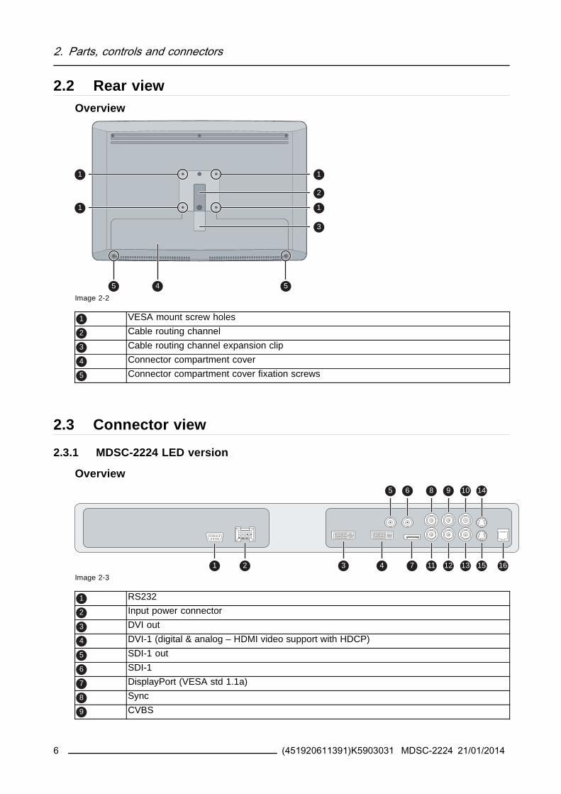
2 Parts controls and connectors
10 CVBS out
11 RPr
12 GY
13 BPb
14 S-Video out
15 S-Video
16 Service
232 MDSC-2224 MNA version
Overview
1 2 4 6 7 8 9 10 11 15 16 17 19
125 13 14 18
20
3
Image 2-4
1 Optical 10Gb Ethernet SFP+ interface
2 LED2
Orange blinking Activity = (Tx) or (Rx)
Off No network activity3 LED1
Green Link is active
Off No active network connection4 LED3
Green Power on normal operation
Off System not powered
Orange blinking Error5 Micro USB interface
6 USB 20 type A interface
7 RS232
8 Input power connector
9 DVI out
10 DVI-1 (digital amp analog ndash HDMI video support with HDCP)
11 DisplayPort (VESA std 11a)
12 Sync
13 CVBS
14 CVBS out
15 RPr
16 GY
17 BPb
18 S-Video out
19 S-Video
20 Service
(451920611391)K5903031 MDSC-2224 21012014 7
2 Parts controls and connectors
() Nexxis OR functionality for more detailed information on Barcorsquos Nexxis integrated OR solution pleaserefer to the dedicated user guides Please visit mybarcocom to obtain these user guides
24 Connector pin assignments
241 Input power connector
Overview
Image 2-5
Pin Function
1 GND
2 Not connected
3 +24 VDC
4 GND
5 Shield
6 +24 VDC
The ground and the shield connections on the power input connector have no Protec-tive Earth function A Protective Earth connection is provided via a dedicated pin (seeimage 3-8)
242 DVIndash1 connector
Overview
Image 2-6
Pin Function
1 D2_Rx- (TMDS)
2 D2_Rx+ (TMDS)
3 GND (data 2 shield)
4 Not connected
5 Not connected
6 SCL (for DDC)
7 SDA (for DDC)
8 Analog vertical sync
9 D1_Rx- (TMDS)
10 D1_Rx+ (TMDS)
11 GND (data 1 shield)
8 (451920611391)K5903031 MDSC-2224 21012014
2 Parts controls and connectors
12 Not connected
13 Not connected
14 +5V input (DDC supply) ()
15 GND (cable sense)
16 Hot plug detect ()
17 D0_Rx- (TMDS)
18 D0_Rx+ (TMDS)
19 GND (data 0 shield)
20 Not connected
21 Not connected
22 GND (clock shield)
23 CK_Rx+ (TMDS)
24 CK_Rx- (TMDS)
C1 Analog Red
C2 Analog Green
C3 Analog Blue
C4 Analog horizontal sync
C5 Analog GND return (analog R G B)
() +5 VDC output selectable on either pin 14 or 16 via the OSD menu (+5V plusmn 10 500mA (max))
243 DVI out connector
Overview
Image 2-7
Pin Function
1 D2_Rx- (TMDS)
2 D2_Rx+ (TMDS)
3 GND (data 2 shield)
4 Not connected
5 Not connected
6 SCL (for DDC)
7 SDA (for DDC)
8 Not connected
9 D1_Rx- (TMDS)
10 D1_Rx+ (TMDS)
11 GND (data 1 shield)
12 Not connected
13 Not connected
14 +5V output ()
15 GND (cable sense)
16 Hot plug detect
17 D0_Rx- (TMDS)
(451920611391)K5903031 MDSC-2224 21012014 9
2 Parts controls and connectors
18 D0_Rx+ (TMDS)
19 GND (data 0 shield)
20 Not connected
21 Not connected
22 GND (clock shield)
23 CK_Rx+ (TMDS)
24 CK_Rx- (TMDS)
() +5 VDC output always available (+5V plusmn 10 500mA (max))
244 RS232 connector
Overview
Image 2-8
Pin Function
1 Not connected
2 Rx (driven by host)
3 Tx (driven by display)
4 Not connected
5 Ground
6 Not connected
7 Not connected
8 Not connected
9 Not connected
245 USB connector
Overview
Image 2-9
Pin Function
1 +5 VDC
2 Data mdash
3 Data +
4 GND
10 (451920611391)K5903031 MDSC-2224 21012014
2 Parts controls and connectors
246 Mini USB connector
Overview
12345
Image 2-10
Pin Function
1 +5 VDC
2 Data mdash
3 Data +
X Not connected
4 GND
247 DisplayPort connector
Overview
19 17 15 13 11 9 7 5 3 1
20 18 16 14 12 10 8 6 4 2
Image 2-11
Pin Function
1 ML_Lane 0 (p)
2 GND
3 ML_Lane 0 (n)
4 ML_Lane 1 (p)
5 GND
6 ML_Lane 1 (n)
7 ML_Lane 2 (p)
8 GND
9 ML_Lane 2 (n)
10 ML_Lane 3 (p)
11 GND
12 ML_Lane 3 (n)
13 CONFIG1
14 CONFIG2
15 AUX CH (p)
16 GND
17 AUX CH (n)
18 Hot Plug
19 Return
20 DP_PWR (+33 VDC)
(451920611391)K5903031 MDSC-2224 21012014 11
2 Parts controls and connectors
248 S-Video and S-Video-out connector
Overview
Image 2-12
Pin Function
1 Ground (Y)
2 Ground (C)
3 Luminance (Y)
4 Chroma (C)
SG Shielded Ground
12 (451920611391)K5903031 MDSC-2224 21012014
3 Display installation
3 DISPLAY INSTALLATION
31 VESA mount installationOverviewThe display supports mounting arm amp stands according to the VESA 100 mm standard
CAUTION Use an arm that is approved by VESA
CAUTION Use an arm that can support a weight of least 10 kg (2205 lbs)
The monitor VESA interface has been designed for a safety factor 6 (to support 6 timesthe monitor weight) In the medical system use an arm with suitable safety factor(IEC60601ndash1)
To mount the display to an arm stand1 Attach the arm stand firmly to the panel using the included 4 hexagonal screws (M4 x 25 mm) and the
dented washers Use the included Allen key to fix the screws
Image 3-1
CAUTION The 4 screws included with this display (M4 x 25 mm) can be used for anexternal VESA arm interface with a thickness of up to 5mm
If due to the thickness of the external VESA arm interface (=V) the length of the providedscrews (=L) is not suitable consider the following rule
Lmin = V + 20mm
Lmax = V + 30mm
(451920611391)K5903031 MDSC-2224 21012014 13
3 Display installation
32 Cover removalTo remove the connector compartment cover1 Loosen the screws fixing the connector compartment cover
2 Slide the cover downwards to remove it from the display
1
2 2
1
Image 3-2
33 Video input connection
About video input connectionsThe MDSC-2224 can have multiple different video inputs connected (depending on the display version)Switching between the different inputs can be easily done by pressing the direct access key for this Seethe dedicated section for more info
Futhermore if more than one video source is connected the Picture in Picture (PiP) and Side-by-Side(SbS) functionality becomes available allowing you to view two different video inputs at once Pleaserefer to the dedicated chapter for more info on how to activate and use the PiP and SbS features on yourMDSC-2224
This chapter describes how to connect the different video input types for each version of the MDSC-2224
331 MDSC-2224 LED version
To connect the video inputs1 Connect one or more of the available video source(s) to the corresponding video inputs using the ap-
propriate video cable(s)
4 5 6 7 8
1 2 3
9
Image 3-3
DVI or VGA () 4
DisplayPort 5
14 (451920611391)K5903031 MDSC-2224 21012014
3 Display installation
SDI 1
RGBS 6 7 8 2
RGB (SOG) 6 7 8
YPbPr 7 8 6
CVBS 3
S-Video 9
() PC analog (VGA) input source can be connected to the DVI-I input connector using a DVI-I to VGAadapter The use of an adapter cable of at least 015 m long will allow an easy placement inside the cablecover
332 MDSC-2224 MNA version
To connect the video inputs1 Connect one or more of the available video source(s) to the corresponding video inputs using the ap-
propriate video cable(s)
4 5 6 7 8
1 2
93
Image 3-4
Nexxis 3
DVI or VGA () 4
DisplayPort 5
RGBS 6 7 8 1
YPbPr 7 8 6
CVBS 2
S-Video 9
() PC analog (VGA) input source can be connected to the DVI-I input connector using a DVI-I to VGAadapter The use of an adapter cable of at least 015 m long will allow an easy placement inside the cablecover
(451920611391)K5903031 MDSC-2224 21012014 15
3 Display installation
34 Video output connection
About video output connectionsBeside the video input connections the MDSC-2224 also has video output capabilities allowing you toloop-through certain video inputs connected with the MDSC-2224 to another display projector videorecorder
This chapter describes how to make use of the video output connections available for each version of theMDSC-2224
341 MDSC-2224 LED version
To connect the video outputs1 Connect one or more of the available video sink(s) to the corresponding video outputs using the appro-
priate video cable(s)
4
1 2 3
Image 3-5
SDI 1
CVBS 2
S-Video 3
DVI 4 (to be configured in OSD menu)
342 MDSC-2224 MNA version
To connect the video outputs1 Connect one or more of the available video sink(s) to the corresponding video outputs using the appro-
priate video cable(s)
16 (451920611391)K5903031 MDSC-2224 21012014
3 Display installation
3
1 2
Image 3-6
CVBS 1
S-Video 2
DVI 3 (to be configured in OSD menu)Nexxis 3 (to be configured in OSD menu)
35 Nexxis OROverviewConnecting your MDSC-2224 to Barcorsquos Nexxis OR system allows you to distribute video graphics audioand computer data over the IP network in raw uncompressed format inside the operating room and evenbetween surgical suites
To connect your MDSC-2224 to Barcorsquos Nexxis OR system connect the 10Gb Ethernet interface to yourNexxis switch More info about Nexxis OR and how to configure the MDSC-2224 in your network is avail-able in the dedicated user guides Please visit wwwbarcocom to obtain these user guides
Nexxis OR is only available on the MDSC-2224 MNA version
36 Power supply connection
To connect the power supply1 Connect the supplied external DC power supply unit to the +24 VDC power input of your MDSC-2224
display
2 Plug the other end of the external DC power supply into a grounded power outlet by means of theproper power cord delivered in the packagingNote The ground and the shield connections on the power input connector have no Protective Earth
function A Protective Earth connection is provided via a dedicated pin (see image 3-8)
(451920611391)K5903031 MDSC-2224 21012014 17
3 Display installation
Image 3-7
Protective earth pin1 Earth the MDSC-2224 by connecting the protective earth pin to a grounded outlet by means of an
AWG18 (max 6ft 18m long) wire
1
Image 3-8
37 Cable routing
To route the cables1 For displays mounted to a VESA arm with internal cable routing provisions route all cables through the
cable routing channel then reinstall the connector compartment cover
8a
Image 3-9
18 (451920611391)K5903031 MDSC-2224 21012014
3 Display installation
OrFor all other mounting options remove the cable routing channel expansion clip from the connectorcompartment cover and route all cables through it while reinstalling the cover
8b
Image 3-10
WARNING When the display is assembled in the medical system take care of the fixa-tion of all cables to avoid unwanted detachment
(451920611391)K5903031 MDSC-2224 21012014 19
3 Display installation
20 (451920611391)K5903031 MDSC-2224 21012014
4 Daily operation
4 DAILY OPERATION
41 Keyboard activationdeactivation
To activate the keyboardIn order to avoid unwanted or accidental activation of the OSD keyboard a lockunlock mechanism hasbeen implemented This means that before the OSD keyboard can be used to change any of the settingof the display it needs to be unlocked
1 Swipe a finger from the power button zone to the left for about 12 cm
Image 4-1
As a result the keys will light up and are now available for further actions However if no further actionsare taken within the following 10 seconds the keyboard backlight will dim and the keys will be lockedagain
To deactivate the keyboard1 The keyboard will automatically lock after 10 seconds of inactivity except while navigating the OSD
menu during which it remains unlocked
As a result Its backlight switches off to indicate the keyboard is lockedOrmanually lock the keyboard by sweeping your finger over the bottom right hand side of your display
Image 4-2
(451920611391)K5903031 MDSC-2224 21012014 21
4 Daily operation
Keyboard backlight rsquoAlways onrsquo modeWhen used with keyboard Backlight lsquoAlways onrsquo (factory setting is lsquoOn with touchrsquo) the lock unlock statusof the keyboard cannot be linked to the on off status of the keyboard backlight (the backlight is alwayson in this mode except when in Power Save of Soft Off)
Therefore the keyboard lock status is being signaled by a slow blinking of the keyboard backlight betweenon and off at a rate of one cycle per second The Keyboard will automatically lock after 10 minutes
Keyboard backlight rsquoOn withtouchrsquo (Factory default)
Keyboard backlight rsquoAlways onrsquo(Custom setting)
Keyboard Locked Keyboard backlight is off andremains off while a key is pressed
Keyboard backlight is on andstarts slowly blinking between onand off while key is pressed
Keyboard Unlocked Keyboard backlight is on and dimsslightly while a key is pressed
Keyboard backlight is on and dimsslightly while a key is pressed
Keyboard AUTO-lock Timeout 10 seconds 10 minutes
42 Keyboard backlight
About the keyboard backlightBy default only the stand-by key is visible After keyboard activation (see Keyboard activationdeactiva-tion page 21) the backlight of all keys is switched on for a few seconds When you touch any of thesekeys again while the backlight is on the function of the key is executed If no further action is taken withinthe time-out the keyboard backlight is switched off again
The keyboard backlight auto-dim function can be disabled in the OSD menu so that thekeyboard backlight is always on (Keyboard Backlight)
43 OnOff switching
To switch on your display1 Activate the power supply through the switch located on the external power supply
2 While your display is off press and hold the stand-by key for approximately 3 seconds (or until thekeyboard backlight stops blinking)
To minimize the power consumption also the external power supply has to be switchedoff
To switch off your display1 While your display is switched on unlock the keyboard see Keyboard activationdeactivation page
21
2 Press and hold the stand-by key for approximately 3 seconds (or until the keyboard backlight stopsblinking and switches off)
22 (451920611391)K5903031 MDSC-2224 21012014
4 Daily operation
While pressing the stand-by key to switch off the display the front key illumination willblink
44 Power led statusAbout the the power led statusThe behavior of the power led shows the status of the unit
bull No led visible the status of the unit is hard OFF (the switch of the power supply is OFF)
bull Led is fading between on and off the status of the unit is soft OFF (when pushing the standby buttonthe unit is on or off)
bull Led is full orange the unit is in power save mode (no signal amp power save mode enabled)
bull Led is blinking greenorange the unit is in searching mode (looking for a signal)bull Led is full green the unit has an image on the screen
45 OSD menu activationTo activate the OSD menu1 If not already done so switch on the display by pressing and holding the stand-by key for approxi-
mately 3 seconds
2 Switch on the front key illumination by activating the keyboard (see Keyboard activationdeactivationpage 21)
3 Touch the MenuEnter key
As a result the OSD main menu comes up in the bottom right corner of the screen If no further actionsare taken within the following 30 seconds the OSD menu will disappear again
The time-out of the OSD menu automatic close function can be adjusted or disabled inthe OSD menu (OSD Time-out)
The OSD menu position can be adjusted in the OSD menu (OSD Hor Pos and OSD VertPos)
46 OSD menu navigation
OSD menu structure explainedBelow is on example of how the OSD menu structure looks like
(451920611391)K5903031 MDSC-2224 21012014 23
4 Daily operation
Picture
Brightness 50
Contrast 50
Saturation 30
Profile Factory
Color temperature 6500K
Gamma Native
Sharpness 10
DVI 1280x80060Hz
1 6
5
32 4
Image 4-3
1 Menu
2 Sub-menu
3 Status bar
4 Legenda (shows the functionality associated to each keyboard key)
5 SelectorSlider
6 Item
To navigate through the OSD menu
Image 4-4
bull Press the key to open the OSD menubull Use the or key to scroll to the desired menu page
bull When the desired Menu page is highlighted press the key to select the top menu item that will behighlighted
bull Use the or keys to move to other Menu Items then press the key to select it
bull If the selected menu item is controlled by a slider use the or keys to adjust the item value thenpress the key to confirm
bull If the selected menu item is a multiple choices menu use the or keys to select the desired optionthen press the key to confirm
bull Press again or key to select other Menu items or exit from the Menu page by pressing the key
47 Shortkey functions
About shortkey functionsThe concept of shortkey functions is to present a selection of commonly used functions immediately avail-able without the need to navigate through the OSD Menu
The different available shortkey functions are
24 (451920611391)K5903031 MDSC-2224 21012014
4 Daily operation
bull Main source selectionbull Multi-image configuration
bull Zoom factor selection
bull Brightness adjustment
Unlike the extended keyboard functions (described in next chapter) the shortkey func-tionality is immediately available without the need to first enable this in the OSD menu
When the extended keyboard functionality is enabled all the shortkey functions de-scribed below (except for the brightness adjustment) will no longer be available andwill be replaced by the corresponding extended keyboard functions described in thenext chapter
Overview of shortkeys
1 2 3 4 5
Image 4-5
1 Main source selection
2 Multi-image configuration
3 Zoom factor selection
4 Brightness decrease
5 Brightness increase
471 Main source selection
To quickly select the main source1 Use the Input selection key ( ) to scroll through all the possible input signals to select the main input
source
Available main source options dependent on display model
When the extended keyboard functionality is enabled this shortkey functions will nolonger be available and will be replaced by the corresponding extended keyboard func-tions described in the next chapter
472 Multi-image configuration
To quickly select the multi-image configuration1 Use the PiP selection key ( ) to scroll through all possible configurations of Picture-in-Picture (PiP) and
Side-by-Side (SbS)The different PiPSbS options are- Small PiP 30 of Primary height in top-right corner- Large PiP 50 of Primary height in top-right corner- Side-by-Side Primary and Secondary input of equal height
(451920611391)K5903031 MDSC-2224 21012014 25
4 Daily operation
Only a subset of multi-image configuration settings is available via this shortkey func-tion More multi-image configuration settings can be selected in the OSD menus
When the extended keyboard functionality is enabled this shortkey functions will nolonger be available and will be replaced by the corresponding extended keyboard func-tions described in the next chapter
473 Zoom factor selection
To quickly select the zoom factor1 Use the Image zoom key ( ) to select one of the available zoom factors
When the extended keyboard functionality is enabled this shortkey functions will nolonger be available and will be replaced by the corresponding extended keyboard func-tions described in the next chapter
474 Brightness adjustment
To quickly adjust the brightness1 While no OSD Menu is on the screen press the Brightness decrease ( ) or Brightness increase ( )
keys to adjust the brightness as desired
Brightness
50
Image 4-6
When the extended keyboard functionality is enabled this shortkey functions will re-main available
48 Extended keyboard functions
About extended keyboard functionsThe concept of the extended keyboard is to present a large selection of functions immediately availableto the user without the need to navigate through the OSD Menu
Once enabled through dedicated OSD menu function by simply pressing one of the first 3 keys on the leftthe user is presented with a list of new selections displayed on screen the new choices can be selectedby using each of the key just below the OSD text
If two options are available for one key the first key press will select the upper option a second pressselects the lower option
The different available extended keyboard functions are
26 (451920611391)K5903031 MDSC-2224 21012014
4 Daily operation
bull Main source selectionbull Second source selection
bull Multi-image configuration
bull Color temperature selectionbull Image size selection
bull Zoom factor selection
Unlike the shortkey functions (described before) the extended keyboard functionalitymust be first enabled in the OSD menu before you can make use of it Please refer to thededicated section in this manual for more details on how to enabledisable the extendedkeyboard functions
When the extended keyboard functionality is enabled all the shortkey functions de-scribed in previous chapter (except for the brightness adjustment) will no longer beavailable and will be replaced by the corresponding extended keyboard functions de-scribed below
Overview of extended keyboard
1 2 3
Image 4-7
Main source selection1
Second source selection
2 Multi-image configuration
Color temperature selection
Image size selection3
Zoom factor selection
481 Main source selection
To quickly select the main source1 While no OSD Menu is on the screen press the Input selection key ( ) to bring up the main source
quick selection menu
2 Toggle the available main source options by pressing the key corresponding to the desired optionIf two options are available for one key the first key press will select the upper option a second pressselects the lower optionThe current selection is marked in red
3 Press the stand-by key ( ) to confirm your choice and exit the main source quick selection menu
(451920611391)K5903031 MDSC-2224 21012014 27
4 Daily operation
Main source
VGA
DP
R G B
Y Pb Pr
S-Video
CVBS
DVI
SDI Nexxis 2nd Source
EXIT
Image 4-8
Note Available main source options dependent on display model
482 Second source selection
To quickly select the second source1 While no OSD Menu is on the screen press the Input selection key ( ) to bring up the main source
quick selection menu
2 Press the key to switch to the 2nd source quick selection menu
3 Toggle the available second source options by pressing the key corresponding to the desired optionIf two options are available for one key the first key press will select the upper option a second pressselects the lower optionThe current selection is marked in red
4 Press the stand-by key ( ) to confirm your choice and exit the second source quick selection menu
2nd Source
VGA
DP
R G B
Y Pb Pr
S-Video
CVBS
DVI
SDI Nexxis Main source
EXIT
Image 4-9
Note Available second source options dependent on display model
483 Multi-image configuration
To quickly select the multi-image configuration1 While no OSD Menu is on the screen press the PiP selection key ( ) to bring up the multi-image
configuration quick selection menu
2 Toggle the available multi-image configurations by pressing the key corresponding to the desired optionThe current selection is marked in red
3 Press the stand-by key ( ) to confirm your choice and exit the multi-image configuration quick selectionmenu
28 (451920611391)K5903031 MDSC-2224 21012014
4 Daily operation
Multi image config
Native Aspect Fill Small Large None
EXIT
Image 4-10
484 Common Functions Transfer function selection
To quickly select the transfer function1 While no OSD Menu is on the screen press the Image zoom key ( ) to bring up the common functions
quick selection menu
2 Toggle the available transfer function settings by pressing the key corresponding to the desired optionThe current selection is marked in red
3 Press the stand-by key ( ) to confirm your choice and exit the common functions quick selection menu
Common Functions
ITU 709 6500degK X-Ray Native Aspect Zoom
10
EXIT
Image 4-11
Note Only a subset of transfer function settings is available via this quick selection menu More transferfunction settings can be selected in the OSD menus
485 Common Functions Image size selection
To quickly select the image size1 While no OSD Menu is on the screen press the Image zoom key ( ) to bring up the common functions
quick selection menu
2 Toggle the available image size settings by pressing the key corresponding to the desired optionThe current selection is marked in red
3 Press the stand-by key ( ) to confirm your choice and exit the common functions quick selection menu
Common Functions
ITU 709 6500degK X-Ray Native Aspect Zoom
10
EXIT
Image 4-12
Note Only a subset of image size settings is available via this quick selection menu More image sizesettings can be selected in the OSD menus
(451920611391)K5903031 MDSC-2224 21012014 29
4 Daily operation
486 Common Functions Zoom factor selection
To quickly select the zoom factor1 While no OSD Menu is on the screen press the Image zoom key ( ) to bring up the common functions
quick selection menu
2 Toggle the available zoom factors by repeatedly pressing the key until the desired zoom factor isshown
3 Press the stand-by key ( ) to confirm your choice and exit the common functions quick selection menu
Common Functions
ITU 709 6500degK X-Ray Native Aspect Zoom
10
EXIT
Image 4-13
49 Menu lockingunlocking
To lockunlock the menuThe keyboard can be locked from the Menu to avoid unwanted access to OSD functions When the key-board is LOCKED only the OSD Menu key ( ) and the Stand-by key ( ) are active When the Menu OSDkey is pressed the Menu Locked window appears
1 To unlock the keyboard the following sequence of keys need to be pressed
Each time a key is pressed an asterisk is shown in the square boxes
After pressing the fourth key if the sequence is correct the main OSD menu is activated To unlock thekeyboard permanently the specific OSD function is required
Keyboard lockSequence 5 - 6 - 6 - 3
Image 4-14
30 (451920611391)K5903031 MDSC-2224 21012014
5 Advanced operation
5 ADVANCED OPERATION
51 OSD picture menu
Overview
bull Profile
bull Brightnessbull Contrast
bull Saturationbull Color temperature
bull Gamma
bull Sharpness
511 Profile
About profilesTo select a profile means to load a set of predefined video parameters like Brightness Contrast Satura-tion Input selection (Primary amp Secondary) Multi-image layout selection etc
The user can modify the default video parameters associated to each profile and save the new parameterssetting under the User 1 User 2 or User 3 profile The Factory and X Ray profiles can be temporarymodified but the factory default canrsquot be overwritten and can always be recalled through the recall profilemenu item
The available profiles for your display are
bull Factory
bull X Ray
bull User 1bull User 2
bull User 3
To select a profile1 Bring up the OSD main menu
2 Navigate to the Picture menu
3 Enter the Profile submenu
4 Select one of the available profiles and confirm
512 Brightness
To adjust the brightness level1 Bring up the OSD main menu
2 Navigate to the Picture menu
3 Enter the Brightness submenuThe command bar Brightness is highlighted
4 Set the brightness level as desired and confirm
(451920611391)K5903031 MDSC-2224 21012014 31
5 Advanced operation
The selected brightness is maintained at a constant level by the automatic backlightstabilization function
The brightness level can also be adjusted through a shortkey function
Brightness level is adjusted by controlling the backlight illumination only
513 Contrast
To adjust the contrast level1 Bring up the OSD main menu
2 Navigate to the Picture menu
3 Enter the Contrast submenuThe command bar Contrast is highlighted
4 Set the contrast level as desired and confirm
514 Saturation
To adjust the saturation level1 Bring up the OSD main menu
2 Navigate to the Picture menu
3 Enter the Saturation submenuThe command bar Saturation is highlighted
4 Set the saturation level as desired and confirm
515 Color temperature
About color temperature presetsThe available color temperature presets for your display are
bull 5600Kbull 6500K
bull 7600Kbull 9300K
bull ITU 709
bull Nativebull User
32 (451920611391)K5903031 MDSC-2224 21012014
5 Advanced operation
Factory calibration ndash White point
The White Color points associated with the Color Temperature 5600K 6500K 7600K or9300K are factory calibrated with a consequent reduction of the maximum luminancecompared to Native Color Temperature
Factory calibration ndash Color space
When ITU 709 is selected the White Color point and the RGB color primaries are ad-justed according to the target HDTV sRGB color space defined in the ITU-709 recom-mendation RGB primary calibration is performed within the physical limitation of theLCD panel used
Only in case the User preset has been selected it is possible to get access to the colorregulation commands described hereafter
To select a color temperature preset1 Bring up the OSD main menu
2 Navigate to the Picture menu
3 Enter the Color Temperature submenu
4 Select one of the available color temperature presets and confirmNote If you selected the User color temperature preset a new menu will be displayed allowing you to
manually adjust the gain and offset of red green and blue
516 Gamma
About gamma presetsThe available gamma presets for your display are
bull 18
bull 20
bull 22bull 24
bull Native (no correction curve is applied)bull X-ray (grayscale levels are following closely the DICOM curve)
To select a gamma preset1 Bring up the OSD main menu
2 Navigate to the Picture menu
3 Enter the Gamma submenu
4 Select one of the available gamma presets and confirm
517 Sharpness
To adjust the sharpness level1 Bring up the OSD main menu
2 Navigate to the Picture menu
(451920611391)K5903031 MDSC-2224 21012014 33
5 Advanced operation
3 Enter the Sharpness submenuThe command bar Sharpness is highlighted
4 Set the sharpness level as desired and confirm
52 Picture Advanced menuOverview
bull Black Levelbull Smart Video
bull Image Positionbull Auto Adjustment
bull Phase
bull ClockLine
521 Black Level
About black levelThis command allows to add or subtract an offset to the input video signal (available only on video formats)
To adjust the black level1 Bring up the OSD main menu
2 Navigate to the Picture advanced menu
3 Enter the Black Level submenuThe command bar Black Level is highlighted
4 Set the black level as desired and confirm
522 Smart Video
About Smart VideoThis function allows to reduce the video latency in the monitor if its frame rate is in the range of 50 - 60Hz To achieve a minimum latency select one of the surgical modes
The available Smart Video presets for your display are
bull Diagnostic (best picture quality)bull Surgical (low latency)
bull Surgical 1 (low latency optimized for fast moving images)
To select a Smart Video preset1 Bring up the OSD main menu
2 Navigate to the Picture advanced menu
3 Enter the Smart Video submenu
4 Select one of the available Smart Video presets and confirm
34 (451920611391)K5903031 MDSC-2224 21012014
5 Advanced operation
523 Image Position
This menu item is only available when VGA input is connected
To adjust the image position1 Bring up the OSD main menu
2 Navigate to the Picture advanced menu
3 Enter the Image Position submenuA small OSD menu will be activated indicating the horizontal and vertical image position offset
4 Use the and keys to move the picture up and down
5 Use the and keys to move the picture left and right
6 When finished use the key to exit from the small OSD menu
524 Auto Adjustment
This menu item is only available when VGA input is connected
About auto adjustmentWhen auto adjustment is activated the phase and clock per line parameters are automatically adjusted
To activate auto adjustment1 Bring up the OSD main menu
2 Navigate to the Picture advanced menu
3 Enter the Auto Adjustment submenuThe automatic picture adjustment is activated the phase and clock per line parameters are automati-cally adjusted
525 Phase
This menu item is only available when VGA input is connected
About phaseIf the result of the Auto Adjustment procedure described above isnrsquot satisfactory the Phase can be man-ually adjusted by following this procedure
To manually adjust the phase1 Bring up the OSD main menu
2 Navigate to the Picture advanced menu
3 Enter the Phase submenuThe command bar Phase is highlighted
4 Set the phase as desired and confirm
(451920611391)K5903031 MDSC-2224 21012014 35
5 Advanced operation
526 ClockLine
This menu item is only available when VGA input is connected
About clocklineIf the result of the Auto Adjustment procedure described above isnrsquot satisfactory the ClockLine can bemanually adjusted by following this procedure
To manually adjust the phase1 Bring up the OSD main menu
2 Navigate to the Picture advanced menu
3 Enter the ClockLine submenuThe command bar ClockLine is highlighted
4 Set the clockline as desired and confirm
53 Display Format menu
Overview
bull Main Source (Primary Source)bull Component Mode
bull Zoom
bull Image Sizebull 2nd Picture Mode
bull 2nd Picture Sourcebull 2nd Picture Position
bull Picture Swap
531 Main Source (Primary Source)
About main sourcesThe available main sources for your display are
bull Auto Search
bull Compositebull S-Video
bull Componentbull PC Analog
bull DVI 1bull DVI 2
bull SDI 1
bull SDI 2bull Nexxis
bull DisplayPort
36 (451920611391)K5903031 MDSC-2224 21012014
5 Advanced operation
Available main sources dependent on display model
The main source can also be selected through a shortkey function or via the extendedkeyboard functionality
To select the main source1 Bring up the OSD main menu
2 Navigate to the Display Format menu
3 Enter the Main Source submenu
4 Select one of the available main source and confirmNote If you selected the Auto Search preset the display will automatically detect the connected signal
532 Component Mode
About component modesThe available component modes for your display are
bull YPbPr
bull RGB
To select the component mode1 Bring up the OSD main menu
2 Navigate to the Display Format menu
3 Enter the Component Mode submenu
4 Select one of the available component modes and confirm
533 Zoom
About zoomThe available zoom factors for your display are
bull None
bull 10bull 20
bull 30bull 40
bull 50
The zoom factor can also be selected through a shortkey function or via the extendedkeyboard functionality
To select a zoom factor1 Bring up the OSD main menu
2 Navigate to the Display Format menu
(451920611391)K5903031 MDSC-2224 21012014 37
5 Advanced operation
3 Enter the Zoom submenu
4 Select one of the available zoom factors and confirm
534 Image Size
About image sizeThe available image sizes for your display are
bull Full Screen (fill the screen image aspect-ratio can be altered)
bull Aspect (fill the screen on largest dimension no modification in image aspect-ratio)bull Native (input pixel to LCD pixel mapping no scaling)
In Aspect and Native the image may be displayed with black bars on topbottom orleftright
The image size can also be selected via the extended keyboard functionality
To select the image size1 Bring up the OSD main menu
2 Navigate to the Display Format menu
3 Enter the Image Size submenu
4 Select one of the available image sizes and confirm
535 2nd Picture Mode
About 2nd picture modesThe available 2nd picture modes for your display are
bull Off
bull Small PiP 30 of Primary height in top-right cornerbull Large PiP 50 of Primary height in top-right corner
bull Side-by-Side Primary and Secondary input of equal height
bull SbS Native The 2 images are displayed with input pixel to LCD pixel mapping with image crop ifnecessary
bull SbS Fill Both images scaled to fill half of the screen with image crop if necessary
The 2nd picture mode (multi-image configuration) can also be selected via the extendedkeyboard functionality
To select the 2nd picture mode1 Bring up the OSD main menu
2 Navigate to the Display Format menu
3 Enter the 2nd Picture Mode submenu
4 Select one of the available 2nd picture modes and confirm
38 (451920611391)K5903031 MDSC-2224 21012014
5 Advanced operation
Multi image in Full HD available with any combination of input sources
Multi image in SD video available with any combination of input source except Compos-ite amp S-video
536 2nd Picture Source
About 2nd picture sourcesThe available 2nd picture sources for your display are
bull Auto Searchbull Composite
bull S-Videobull Component
bull PC Analog
bull DVI 1bull DVI 2
bull SDI 1bull SDI 2
bull Nexxisbull DisplayPort
The 2nd picture source can also be selected via the extended keyboard functionality
Independent Transfer Function
Gamma and Color temperature for the 2nd Picture Souce are always set to Native and6500K independently from the Transfer Function applied to the Main Picture SourceFor a perfect visualization of a X-ray image please select the X-ray input signal as Mainpicture and if needed the Video image as 2nd picture
To select the 2nd picture source1 Bring up the OSD main menu
2 Navigate to the Display Format menu
3 Enter the 2nd Picture Source submenu
4 Select one of the available 2nd picture sources and confirm
537 2nd Picture Position
About 2nd picture positionsThe available 2nd picture positions for your display are
bull Top Rightbull Top Left
bull Bottom Rightbull Bottom Left
(451920611391)K5903031 MDSC-2224 21012014 39
5 Advanced operation
To select the 2nd picture position1 Bring up the OSD main menu
2 Navigate to the Display Format menu
3 Enter the 2nd Picture Position submenu
4 Select one of the available 2nd picture positions and confirm
538 Picture Swap
About picture swappingTo swap pictures means to exchange (swap) main and 2nd picture
To swap pictures1 Bring up the OSD main menu
2 Navigate to the Display Format menu
3 Enter the Picture Swap submenu
4 Select the desired setting and confirm
54 Configuration menu
Overview
bull Information
bull Language
bull Failover modebull Extended keyboard
bull OSD settingbull Recall Profile
bull Save Profile
541 Information
About informationThe available information items for your display are
bull Model (commercial type identification)bull Operating Hours (backlight operation hours)
bull Firmware Release (firmware identification)
bull Hardware Version (main board identification)bull Option SDI (SDI module identification)
bull Serial Number ANxxxxxxxxxxxx
To access information1 Bring up the OSD main menu
2 Navigate to the Configuration menu
3 Enter the Information submenuThe different information items are shown
40 (451920611391)K5903031 MDSC-2224 21012014
5 Advanced operation
542 Language
About languagesThe available languages for your display are
bull English
bull Franccedilaisbull Deutsch
bull Espantildeol
bull Italiano
To select the language1 Bring up the OSD main menu
2 Navigate to the Configuration menu
3 Enter the Language submenu
4 Select one of the available languages and confirm
543 Failover mode
About failover modeThis function allows the automatic switch to a defined Backup source when the Main input signal is miss-ing
The display will automatically restore the Main input as soon as the signal is back
The Backup source is the input selected as ldquo2nd Picture Sourcerdquo with ldquo2nd Picture Moderdquo = ldquoOffrdquo
This Main amp Backup combination is stored at the moment the function ldquoFailover moderdquo is set to ldquoEnabledrdquo
Failover Mode is not selectable when either the Main Source or the 2nd Picture Source is set to ldquoAu-tosearchrdquo
Failover mode is automatically disabled when either the Main Source or the 2nd PictureSource is changed A warning message ldquoFailover offrdquo appears on the screen for a fewseconds
Returning to the original Main amp Backup combination will automatically re-enable theFailover feature
For the MNA version only Failover mode will be activated 7 seconds after the Nexxissignal becomes unavailable (delay required to allow a Nexxis layout change)
To enabledisable failover mode1 Bring up the OSD main menu
2 Navigate to the Configuration menu
3 Enter the Failover mode submenu
4 EnableDisable failover mode as desired and confirm
(451920611391)K5903031 MDSC-2224 21012014 41
5 Advanced operation
544 Extended keyboard
About the extended keyboardThe concept of the extended keyboard is to present a large selection of functions immediately availableto the user without the need to navigate through the OSD Menu
Once enabled by simply pressing one of the first 3 keys on the left the user is presented with a list of newselections displayed on screen the new choices can be selected by using each of the key just below theOSD text
If two options are available for one key the first key press will select the upper option a second pressselects the lower option
The different available extended keyboard functions are
bull Main source selection
bull Second source selection
bull Multi-image configurationbull Color temperature selection
bull Image size selectionbull Zoom factor selection
To enabledisable the extended keyboard1 Bring up the OSD main menu
2 Navigate to the Configuration menu
3 Enter the Extended keyboard submenu
4 EnableDisable the extended keyboard as desired and confirm
545 OSD setting
5451 OSD Horizontal Position
To adjust the OSD horizontal position1 Bring up the OSD main menu
2 Navigate to the Configuration menu
3 Enter the OSD setting submenu
4 Select OSD Hor PosThe command bar OSD Hor Pos is highlighted
5 Set the OSD horizontal position as desired and confirm
5452 OSD Vertical Position
To adjust the OSD vertical position1 Bring up the OSD main menu
2 Navigate to the Configuration menu
3 Enter the OSD setting submenu
4 Select OSD Ver PosThe command bar OSD Ver Pos is highlighted
5 Set the OSD vertical position as desired and confirm
42 (451920611391)K5903031 MDSC-2224 21012014
5 Advanced operation
5453 OSD Time-out
About OSD time-outThe available OSD time-out values for your display are
bull 10 Sec
bull 20 Secbull 30 Sec
bull 60 Sec
bull Disabled (=5 minutes)
To adjust the OSD time-out1 Bring up the OSD main menu
2 Navigate to the Configuration menu
3 Enter the OSD setting submenu
4 Select OSD Time-out
5 Select one of the available OSD time-out values and confirm
546 Recall Profile
About recalling profilesTo recall a profile means to restore the default factory settings (Factory and X Ray profiles) or recall theuse defined profiles
The available profiles to recall from your display are
bull Factory
bull X Raybull User 1
bull User 2bull User 3
To recall a profile1 Bring up the OSD main menu
2 Navigate to the Configuration menu
3 Enter the Recall Profile submenu
4 Select one of the available profiles to recall and confirm
547 Save Profile
About saving profilesThe user can modify the default video parameters associated to each profile and save the new parameterssetting under the User 1 User 2 or User 3 profile The Factory and X Ray profiles can be modified butthe factory default canrsquot be overwritten and can always be recalled through the recall profile menu item
The available profiles to save in your display are
bull User 1bull User 2
bull User 3
(451920611391)K5903031 MDSC-2224 21012014 43
5 Advanced operation
To save a profile1 Bring up the OSD main menu
2 Navigate to the Configuration menu
3 Enter the Save Profile submenu
4 Select one of the available profiles to save and confirm
55 System menu
Overview
bull Power on DVI 1
bull Power on DVI 2bull DVI Output
bull Keyboard lock
bull Keyboard backlightbull Power Saving
551 Power on DVI 1
About power on DVI 1This setting allows you to select the pin of DVI port 1 connector on which the +5V DC supply is applied
The available options are
bull Disabled
bull +5V on Pin 14
bull +5V on Pin 16
To select the power on DVI 11 Bring up the OSD main menu
2 Navigate to the System menu
3 Enter the Power on DVI 1 submenu
4 Select one of the available options and confirm
552 Power on DVI 2
About power on DVI 2This setting allows you to select the pin of DVI port 2 connector on which the +5V DC supply is applied
The available options are
bull Disabled
bull +5V on Pin 14bull +5V on Pin 16
To select the power on DVI 21 Bring up the OSD main menu
2 Navigate to the System menu
3 Enter the Power on DVI 2 submenu
44 (451920611391)K5903031 MDSC-2224 21012014
5 Advanced operation
4 Select one of the available options and confirm
553 DVI Output
About DVI outputThis setting allows you to select which digital input to replicate on DVI out
The available options are (depending on display version)
bull DVI 1
bull DVI 2bull Nexxis
bull None
This feature is subject to restrictions in case of Multi-image (PiP SbS)
To select the DVI output1 Bring up the OSD main menu
2 Navigate to the System menu
3 Enter the DVI output submenu
4 Select one of the available options and confirm
554 Keyboard lock
About keyboard lockingThis setting allows you to disable the keyboard functionality and avoid unwanted access to the OSD func-tions
Accessing the OSD menu is only possible after pressing a sequence of keys Please refer to the dedicatedsection for more details (Keyboard lockingunlocking)
To enabledisable keyboard locking1 Bring up the OSD main menu
2 Navigate to the System menu
3 Enter the Keyboard Lock submenu
4 EnableDisable keyboard locking as desired and confirm
555 Keyboard backlight
About the keyboard backlightBy default after lighting up the keyboard backlight will dim again if no further actions are taken within thefollowing 5 seconds However this behavior can be changed so that the keyboard backlight is always on
To adjust the keyboard backlight1 Bring up the OSD main menu
2 Navigate to the System menu
3 Enter the Keyboard Backlight submenu
4 Select one of the available options and confirm
(451920611391)K5903031 MDSC-2224 21012014 45
5 Advanced operation
556 Power Saving
About power savingWhen the active input(s) is (are) missing this setting allows the display to switch off the backlight andenter a low power mode In this status the availability of the selected input is checked periodically
When the unit is in power save mode the unit can exit this power save mode in twocases
1 When a signal is applied on the selected input (or any input in case of auto)
2 By activating the OSD menu see OSD menu activation page 23
To enabledisable power saving1 Bring up the OSD main menu
2 Navigate to the System menu
3 Enter the Power Saving submenu
4 EnableDisable power saving as desired and confirm
46 (451920611391)K5903031 MDSC-2224 21012014
6 Important information
6 IMPORTANT INFORMATION
61 Safety information
General recommendationsRead the safety and operating instructions before operating the device
Retain safety and operating instructions for future reference
Adhere to all warnings on the device and in the operating instructions manual
Follow all instructions for operation and use
Electrical Shock or Fire HazardTo prevent electric shock or fire hazard do not remove cover
No serviceable parts inside Refer servicing to qualified personnel
Do not expose this apparatus to rain or moisture
Type of protection (Electrical)Equipment with external power supply Class I equipment
Degree of safety (flammable anesthetic mixture)Equipment not suitable for use in the presence of a flammable anesthetic mixture with air or with oxygenor nitrous oxide
Non-patient care equipment
bull Equipment primarily for use in a health care facility that is intended for use where contact with a patientis unlikely (no applied part)
bull The equipment may not be used with life support equipmentbull The user is not supposed to touch SIPSOPs and the patient at the same time
Mission critical applicationsWe strongly recommend there is a replacement display immediately available in mission critical applica-tions
Use of Electrical Surgical KnivesProvide as much distance as possible between the electrosurgical generator and other electronic equip-ment (such as monitors) An activated electrosurgical generator may cause interference with them Theinterference can activate the OSD menu of the display and as such disrupt the functionality of the display
Power connection ndash Equipment with external 24 VDC power supply
bull Power requirements The equipment must be powered using the delivered medical approved 24 VDC( ) SELV power supply
bull The medical approved DC ( ) power supply must be powered by the AC mains voltage
bull The power supply is specified as a part of the ME equipment or combination is specified as a MEsystem
bull To avoid the risk of electric shock this equipment must only be connected to a supply mains withprotective earth
bull The equipment should be installed near an easily accessible outlet
bull The equipment is intended for continuous operation
(451920611391)K5903031 MDSC-2224 21012014 47
6 Important information
bull The compliance of this monitor with Medical Safety and EMC requirements has been evaluated usingthe external (optional) Skynet medical power supply model BAR-A159 If a different power supply willbe used further investigation for Safety and EMC requirements have to be performed at system level
Power cords
bull Utilize a UL-listed detachable power cord 3-wire type SJ or equivalent 18 AWG min rated 250 Vmin provided with a hospital-grade type plug 5-15P configuration for 120V application or 6-15P for240V application
bull Do not overload wall outlets and extension cords as this may result in fire or electric shock
bull Mains lead protection (US Power cord) Power cords should be routed so that they are not likely tobe walked upon or pinched by items placed upon or against them paying particular attention to cordsat plugs and receptacles
bull The power supply cord should be replaced by the designated operator only at all timebull Use a power cord that matches the voltage of the power outlet which has been approved and complies
with the safety standard of your particular country
Transient over-voltageIf the device is not used for a long time disconnect it from the AC inlet to avoid damage by transientover-voltage
To fully disengage the power to the device please disconnect the power cord from the AC inlet
ConnectionsAny external connection with other peripherals must follow the requirements of clause 16 of IEC60601-13rd ed or Table BBB201 of IEC 60601-1-1 for the medical electrical systems
Water and moistureThe equipment is IP21 compliant (IPx5 front side only)
The power supply is not approved for IP21 The power supply must be mounted in a flatposition for best resistance to fluids
VentilationDo not cover or block any ventilation openings in the cover of the set When installing the device in acupboard or another closed location heed the necessary space between the set and the sides of thecupboard
Installation
bull Place the equipment on a flat solid and stable surface that can support the weight of at least 3 equip-ments If you use an unstable cart or stand the equipment may fall causing serious injury to a childor adult and serious damage to the equipment
bull Do not allow to climb or rest on the equipment
bull When adjusting the angle of the equipment move it slowly so as to prevent the equipment from movingor slipping off from its stand or arm
bull When the equipment is attached to an arm do not use the equipment as a handle or grip in order tomove the equipment Please refer to the instruction manual of the arm for instructions on how to movethe arm with the equipment
bull Provide full attention to safety during installation periodic maintenance and examination of this equip-ment
48 (451920611391)K5903031 MDSC-2224 21012014
6 Important information
bull Sufficient expertise is required for installing this equipment especially to determine the strength of thewall for withstanding the displayrsquos weight Be sure to entrust the attachment of this equipment to thewall to licensed contractors of Barco and pay adequate attention to safety during the installation andusage
bull Barco is not liable for any damage or injury caused by mishandling or improper installation
General warnings
bull All devices and complete setup must be tested and validated before taking into operation
bull The installer needs to foresee a backup system in case the video falls away
Technical data
bull The monitor is intended for indoor usebull The monitor has been designed to be used in landscape position with a tilt of -10deg (backward) and
+10deg (forward)
bull Power consumption 24VDC 32A maxbull Operating Temperature 10-35degC for performance 0-40degC for safety
bull Operating Humidity 10-90 RH
bull Operating Altitude 3000m maxbull Storage -20 divide +60degC 10 divide 90RH
bull IP Protection IP21 (IPx5 front side only) in vertical positionbull Class I Equipment according to the type of protection against electric shock
bull The monitor is not intended to be sterilized
bull The monitor has not applied parts but the front side of the LCD panel and the plastic enclosure havebeen treated as applied part because considered accidentally touchable by the patient for a time lt1minute
This apparatus conforms toMedical Equipment
3rd edition
ANSIAAMI ES 60601-1 3rd edition 2005 EN 60601 3rd edition 2006 IEC 60601-1 3rd edition (2005)CE (MDD) Class I essential requirements of MDD 9342EEC version 2007 (in effect as of March 2010)CANCSA-C222 No 606011-08
EMC
IEC EN 60601-1-2 2007
EN 55011 CISPR11 (MDSC-2224-MNA Class A MDSC-2224-LED Class B)
National Scandinavian Deviations for CL 172Finland Laite on liitettaumlvauml suojamaadoituskoskettimilla varustettuun pistorasiaan
Norway Apparatet maring tilkoples jordet stikkontakt
Sweden Apparaten skall anslutas till jordat uttag
62 Environmental informationDisposal InformationWaste Electrical and Electronic Equipment
(451920611391)K5903031 MDSC-2224 21012014 49
6 Important information
This symbol on the product indicates that under the European Directive 201219EU governingwaste from electrical and electronic equipment this product must not be disposed of with other municipalwaste Please dispose of your waste equipment by handing it over to a designated collection point for therecycling of waste electrical and electronic equipment To prevent possible harm to the environment orhuman health from uncontrolled waste disposal please separate these items from other types of wasteand recycle them responsibly to promote the sustainable reuse of material resources
For more information about recycling of this product please contact your local city office or your municipalwaste disposal service
For details please visit the Barco website at httpwwwbarcocomenAboutBarcoweee
Turkey RoHS compliance
Tuumlrkiye Cumhuriyeti AEEE Youmlnetmeliğine Uygundur
[Republic of Turkey In conformity with the WEEE Regulation]
中国大陆 ROHS (Chinese Mainland RoHS)根据中国大陆《电子信息产品污染控制管理办法》(也称为中国大 陆RoHS) 以下部分列出了Barco 产品中可能包含的有毒和 或有 害物质的名称和含量中国大陆RoHS 指令包含在中国信息产业部 MCV 标准ldquo 电子信息产品中有毒物质的限量要求 中
According to the China Administration on Control of Pollution Caused by Electronic Information Products(Also called RoHS of Chinese Mainland) the table below lists the names and contents of toxic andorhazardous substances that Barcorsquos product may contain The RoHS of Chinese Mainland is included inthe MCV standard of the Ministry of Information Industry of China in the section Limit Requirements oftoxic substances in Electronic Information Products
零件项目(名称)
Component name
有毒有害物质或元素
Hazardous substances and elements铅Pb
汞
Hg
镉Cd
六价铬Cr6+
多溴联苯
PBB
多溴二苯醚PBDE
印制电路配件
Printed Circuit Assemblies
X O O O O O
液晶面板
LCD panel
X O O O O O
外接电(线)缆External Cables
X O O O O O
內部线路Internal wiring
O O O O O O
金属外壳
Metal enclosure
O O O O O O
塑胶外壳
Plastic enclosure
O O O O O O
散热片(器)
Heatsinks
O O O O O O
风扇
Fan
O O O O O O
50 (451920611391)K5903031 MDSC-2224 21012014
6 Important information
零件项目(名称)
Component name
有毒有害物质或元素
Hazardous substances and elements铅Pb
汞
Hg
镉Cd
六价铬Cr6+
多溴联苯
PBB
多溴二苯醚PBDE
电源供应器
Power Supply Unit
X O O O O O
文件说明书Paper Manuals
O O O O O O
光盘说明书CD manual
O O O O O O
O 表示该有毒有害物质在该部件所有均质材料中的含量均在 SJT 11363-2006 标准规定的限量要求以下
O Indicates that this toxic or hazardous substance contained in all of the homogeneous materials forthis part is below the limit requirement in SJT11363-2006X 表示该有毒有害物质至少在该部件的某一均质材料中的含量超出 SJT 11363-2006 标准规定的限量要求
X Indicates that this toxic or hazardous substance contained in at least one of the homogeneousmaterials used for this part is above the limit requirement in SJT11363-2006
在中国大陆销售的相应电子信息产品(EIP)都必须遵照中国大陆《电子信息产品污染控制标识要求》标准贴上环保使用期限(EFUP)标签Barco产品所采用的EFUP标签(请参阅实例徽标内部的编号使用于制定产品)基于中国大陆的《电子信息产品环保使用期限通则》标准
All Electronic Information Products (EIP) that are sold within Chinese Mainland must comply with theldquoElectronic Information Products Pollution Control Labeling Standardrdquo of Chinese Mainland marked withthe Environmental Friendly Use Period (EFUP) logo The number inside the EFUP logo that Barco uses(please refer to the photo) is based on the ldquoStandard of Electronic Information Products EnvironmentalFriendly Use Periodrdquo of Chinese Mainland
Image 6-1
RoHSDirective 201165EC on the restriction of certain hazardous substances in electrical and electronic equip-ment
According to what declared by our components suppliers this product is RoHS compliant
63 Biological hazard and returns
OverviewThe structure and the specifications of this device as well as the materials used for manufacturing makesit easy to wipe and clean and therefore suitable to be used for various applications in hospitals and othermedical environments where procedures for frequent cleaning are specified
However normal use shall exclude biological contaminated environments to prevent spreading of infec-tions
Therefore use of this device in such environments is at the exclusive risk of Customer In case this deviceis used where potential biological contamination cannot be excluded
(451920611391)K5903031 MDSC-2224 21012014 51
6 Important information
Customer shall implement the decontamination process as defined in the latest edition of the ANSIAAMIST35 standard on each single failed Product that is returned for servicing repair reworking or failureinvestigation to Seller (or to the Authorized Service Provider) At least one adhesive yellow label shall beattached on the top site of the package of returned Product and accompanied by a declaration statementproving the Product has been successfully decontaminated
Returned Products that are not provided with such external decontamination label andor whenever suchdeclaration is missing can be rejected by Seller (or by the Authorized Service Provider) and shipped backat Customer expenses
64 Regulatory compliance information
Indications for useThis device is intended to be used in operation rooms to display images from endoscopic cameras roomand boom cameras ultrasound cardiology PACS anesthesiology and patient information It is not in-tended for diagnosis
FCC Class B (valid for MDSC-2224 LED version)This device complies with Part 15 of the FCC Rules Operation is subject to the following two conditions(1) this device may not cause harmful interference and (2) this device must accept any interference re-ceived including interference that may cause undesired operation
This equipment has been tested and found to comply with the limits for a Class B digital device pursuantto Part 15 of the FCC Rules These limits are designed to provide reasonable protection against harmfulinterference in a residential installation This equipment generates uses and can radiate radio frequencyenergy and if not installed and used in accordance with the instructions may cause harmful interferenceto radio communications However there is no guarantee that interference will not occur in a particularinstallation If this equipment does cause harmful interference to radio or television reception which canbe determined by turning the equipment off and on the user is encouraged to try to correct the interferenceby one or more of the following measures
bull Reorient or relocate the receiving antennabull Increase the separation between the equipment and receiver
bull Connect the equipment into an outlet on a circuit different from that to which the receiver is connectedbull Consult the dealer or an experienced radioTV technician for help
FCC Class A (valid for MDSC-2224 MNA version)This equipment has been tested and found to comply with the limits of a class A digital device pursuantto Part 15 of the FCC rules These limits are designed to provide reasonable protection against harmfulinterference when the equipment is operated in a commercial environment This equipment generatesuses and can radiate radio frequency energy and if not installed and used in accordance with the instruc-tion manual may cause harmful interference to radio communications Operation of this equipment in aresidential area is likely to cause harmful interference in which case the user will be required to correctthe interference at his own expense
Canadian noticeThis ISM device complies with Canadian ICES-001
Cet appareil ISM est conforme agrave la norme NMB-001 du Canada
52 (451920611391)K5903031 MDSC-2224 21012014
6 Important information
65 Cleaning and disinfection
Instructions
bull Be sure to unplug the power cord from the mains when cleaning your LCD monitor
bull Take care not to scratch the front surface with any hard or abrasive materialbull Dust finger marks grease etc can be removed with a soft damp cloth (a small amount of mild deter-
gent can be used on the damp cloth)
bull Wipe off water drop immediately
Possible cleaning solutions
bull 70 percent isopropyl alcoholbull 16 percent aqueous ammonia
bull Cidexreg (24 percent glutaraldehyde solution)
bull Sodium hypochlorite (bleach) 10 percentbull ldquoGreen soaprdquo (USP)
bull 05 percent Chiorhexidine in 70 percent isopropyl alcoholbull Like Cleansafereg optical cleaning liquid
66 Explanation of symbols
Symbols on the deviceOn the device or power supply you may find the following symbols (nonrestrictive list)
Indicates the device meets the requirements of the applicable EC directives
Indicates compliance with Part 15 of the FCC rules (Class A or Class B)
Indicates the device is approved according to the UL Recognition regulations
Indicates the device is approved according to the UL Demko regulations
Indicates the device is approved according to the CCC regulations
Indicates the device is approved according to the VCCI regulations
Indicates the device is approved according to the KC regulations
Indicates the device is approved according to the BSMI regulations
(451920611391)K5903031 MDSC-2224 21012014 53
6 Important information
Indicates the USB connectors on the device
Indicates the DisplayPort connectors on the device
Indicates the manufacturing date
Indicates the temperature limitations1 for the device to safely operate within specs
Indicates the device serial no
Warning dangerous voltage
Caution
Consult the operating instructions
Indicates this device must not be thrown in the trash but must be recycledaccording to the European WEEE (Waste Electrical and Electronic Equipment)directive
Indicates Direct Current (DC)
Indicates Alternating Current (AC)
Stand-by
67 Legal disclaimer
Disclaimer noticeAlthough every attempt has been made to achieve technical accuracy in this document we assume noresponsibility for errors that may be found Our goal is to provide you with the most accurate and usabledocumentation possible if you discover errors please let us know
Barco software products are the property of Barco They are distributed under copyright by Barco NV orBarco Inc for use only under the specific terms of a software license agreement between Barco NV orBarco Inc and the licensee No other use duplication or disclosure of a Barco software product in anyform is authorized
1 Values for xx and yy can be found in the technical specifications paragraph
54 (451920611391)K5903031 MDSC-2224 21012014
6 Important information
The specifications of Barco products are subject to change without notice
TrademarksAll trademarks and registered trademarks are property of their respective owners
Copyright noticeThis document is copyrighted All rights are reserved Neither this document nor any part of it maybe reproduced or copied in any form or by any means - graphical electronic or mechanical includingphotocopying taping or information storage and retrieval systems - without written permission of Barco
copy 2013 Barco NV All rights reserved
68 Technical specifications
OverviewScreen technology TFT AM LCD
Active screen size (diagonal) 611 mm (241)
Active screen size (H x V) 518 x 324 mm (204 x 127)
Aspect ratio (HV) 1610
Resolution W-UXGA (1920 x 1200)
Pixel pitch 0270 mm
Color imaging Yes
Color support 1073 million
Viewing angle (H V) 178deg
Maximum luminance 350 cdmsup2 (typical)
Contrast ratio 10001
Response time (average Grayto Gray)
6 ms (typ)
Housing color White
DVI-I Single Link (digital amp analog ndash HDMI video support with HDCP)
DisplayPort (VESA std 11a)
RGBS
VGA (only computer VESA signals accepted)
S-video
Composite video
Component video
SDIHD-SDI3GSDI
Video input signals
Nexxis fiber optic input
DVI
CVBS
S-video
Video output signals
SDI
Power source requirementsfor external power supply(nominal)
100-250V
LED version 24VDC 23AmaxPower source requirements fordisplay power input MNA version 24VDC 32Amax
(451920611391)K5903031 MDSC-2224 21012014 55
6 Important information
LED version 65WPower consumption
MNA version 85W
Power save mode Yes
Dot clock 165 MHz max (DVI)
OSD languages English French German Spanish Italian
Display dimensions wo stand(W x H x D)
5954 x 414 x 84 mm (2344 x 163 x 331 in)
Power Supply dimensions (Wx H x D)
210 x 103 x 52 mm (827 x 406 x 205 in)
Dimensions packaged (W x Hx D)
685 x 570 x 170 mm (2697 x 2244 x 669 in)
Net weight display wo stand 79 kg (174 lbs) (95 kg (209 lbs) incl power supply and accessories)
Net weight power supply 15 kg (331 lbs)
Net weight packaged wostand
120 kg (265 lbs)
Power supply DC output cablelength
25 m (82 ft)
Mounting standard VESA (100 mm)
Screen protection Protective non-reflective PMMA cover
Recommended modalities Endoscopy Laparoscopy PACS PM US CT MR
Certifications ANSIAAMI ES 60601-1 3rd edition 2005 EN 60601 3rd edition2006 IEC 60601-1 3rd edition (2005) CE (MDD) Class I essentialrequirements of MDD 9342EEC version 2007 (in effect as of March2010) CANCSA-C222 No 606011-08 IEC EN 60601-1-2 2007EN 55011 CISPR11 (MDSC-2224-MNA Class A MDSC-2224 LEDClass B) FCC (A or B depending on model) RoHs compliant IP21(IPx5 front side only)User Guide
Video cable (DVI Dual Link)
Mains cables (European (CEBECKEMA) USA (ULCSA))
Supplied accessories
External power supply
Optional accessories Barco stand (K9302032A)
Power extension cable 10m (K3495066)
Power extension cable 30m (K3495068)Warranty 3 years
Operating temperature 10-35degC for performance 0-40degC for safety
Storage temperature -20 divide +60degC
Operating humidity 10 divide 90 (non-condensing)
Storage humidity 10 divide 90 (non-condensing)
Operating altitude 3000 m max
Storage altitude 12000 m max
Timings DVI-VGAItem Name Pixel x Line Format Hor Fr
(kHz)Vert Fr(Hz)
HorTotal
VertTotal
DVI VGA
1 480i 720 x 487 NTSC 15734 5994 Y N
2 480p59 720 x 480 480p 3147 5994 Y N
3 480p60 720 x 480 480p 315 60 Y N
4 576i 720 x 576 PAL I 15625 50 Y N
5 576p 720 x 576 576p 3125 50 Y N
56 (451920611391)K5903031 MDSC-2224 21012014
6 Important information
Item Name Pixel x Line Format Hor Fr(kHz)
Vert Fr(Hz)
HorTotal
VertTotal
DVI VGA
6 720p29 1280 x 720 720p 2248 2997 Y N
7 720p30 1280 x 720 720p 225 30 Y N
8 720p50 1280 x 720 720p 375 50 Y N
9 720p59 1280 x 720 720p 4496 5994 Y N
10 720p60 1280 x 720 720p 45 60 Y N
11 1080i25 1920 x 1080 1080i 2813 50 Y N
12 1080i29 1920 x 1080 1080i 3372 5994 Y N
13 1080i30 1920 x 1080 1080i 3375 60 Y N
14 1080p29 1920 x 1080 1080p 3372 2997 Y N
15 1080p30 1920 x 1080 1080p 3375 30 Y N
16 1080p50 1920 x 1080 1080p 5625 50 Y N
17 1080p59 1920 x 1080 1080p 67433 5994 Y N
18 1080p60 1920 x 1080 1080p 675 60 Y N
19 DMT0660 604 x 480 VGA 315 60 Y Y
20 DMT0672 604 x 480 VGA 3786 72808 Y Y
21 DMT0675 604 x 480 VGA 375 75 Y Y
22 DMT0685 604 x 480 VGA 43269 85008 Y Y
23 DMT0856 800 x 600 SVGA 3516 5625 Y Y
24 DMT0860 800 x 600 SVGA 3788 6032 Y Y
25 DMT0872 800 x 600 SVGA 4808 7219 Y Y
26 DMT0875 800 x 600 SVGA 46875 75 Y Y
27 DMT0885 800 x 600 SVGA 5374 85061 Y Y
28 DMT1060 1027 x 768 XGA 484 60 Y Y
29 DMT1070 1024 x 768 XGA 564 70 Y(Diagmode)2
Y (Diagmode) 2
30 DMT1075 1024 x 768 XGA 60 75 Y Y
31 DMT1085 1024 x 768 XGA 687 85 Y Y
32 DMT1175 1152 x 864 XGA+ 675 75 Y Y
33 DMT1260G 1280 x 1024 SXGA 64 60 Y Y
34 DMT1275G 1280 x 1024 SXGA 79976 75025 Y Y
35 DMT1285G 1280 x 1024 SXGA 911 85 Y Y
36 DMT1660 1600 x 1200 UXGA 75 60 Y Y
37 CVR1460 1400 x 1050 SXGA+ 64744 59948 Y Y
38 CVT1460 1400 x 1050 SXGA+(VESA)
6532 5998 Y Y
39 CVR1660D 1680 x 1050 WSXGA+1 6467 5988 Y Y
40 CVT1660D 1680 x 1050 WSXGA+2 6529 5995 Y Y
41 CVT 1920 x 1200 WUXGA1 74038 5995 Y Y
42 IBM 640 x 350 315 70 800 449 Y(Diagmode)2
N
43 VESA 640 x 350 379 85 832 446 Y Y
44 VESA 640 x 400 248 563 848 440 N Y
2 OSD Smart Video set to ldquoDiagnosticrdquo
(451920611391)K5903031 MDSC-2224 21012014 57
6 Important information
Item Name Pixel x Line Format Hor Fr(kHz)
Vert Fr(Hz)
HorTotal
VertTotal
DVI VGA
45 IBM 640 x 400 315 700 800 449 Y(Diagmode)2
N
46 VESA 640 x 400 379 850 832 446 Y Y
Timings Comp - SOGItem Name Pixel x Line Format Hor Fr
(kHz)Vert Fr(Hz)
HorTotal
VertTotal
SOG RGBS YPbPr
1 480i 720 x 487 NTSC 15734 5994 Y Y
2 480p59 720 x 480 480p 3147 5994 Y Y
3 480p60 720 x 480 480p 315 60 Y Y
4 576i 720 x 576 PAL I 15625 50 Y Y
5 576p 720 x 576 576p 3125 50 Y Y
8 720p50 1280 x 720 720p 375 50 Y Y
9 720p59 1280 x 720 720p 4496 5994 Y Y
10 720p60 1280 x 720 720p 45 60 Y Y
11 1080i25 1920 x 1080 1080i 2813 50 Y Y
12 1080i29 1920 x 1080 1080i 3372 5994 Y Y
13 1080i30 1920 x 1080 1080i 3375 60 Y Y
14 1080p29 1920 x 1080 1080p 3372 2997 Y Y
15 1080p30 1920 x 1080 1080p 3375 30 Y Y
16 1080p50 1920 x 1080 1080p 5625 50 Y Y
17 1080p59 1920 x 1080 1080p 67433 5994 Y Y
18 1080p60 1920 x 1080 1080p 675 60 Y Y
Timings SDIItem Name Pixel x Line Format Hor Fr
(kHz)Vert Fr(Hz)
HorTotal
VertTotal
SDI(Ypb)
RGBS YPbPr
1 480i 720 x 487 NTSC 15734 5994 Y Y
4 576i 720 x 576 PAL I 15625 50 Y Y
8 720p50 1280 x 720 720p 375 50 Y Y
9 720p59 1280 x 720 720p 4496 5994 Y Y
10 720p60 1280 x 720 720p 45 60 Y Y
11 1080i25 1920 x 1080 1080i 2813 50 Y Y
12 1080i29 1920 x 1080 1080i 3372 5994 Y Y
13 1080i30 1920 x 1080 1080i 3375 60 Y Y
14 1080p29 1920 x 1080 1080p 3372 2997 Y Y
15 1080p30 1920 x 1080 1080p 3375 30 Y Y
16 1080p50 1920 x 1080 1080p 5625 50 Y Y
17 1080p59 1920 x 1080 1080p 67433 5994 Y Y
18 1080p60 1920 x 1080 1080p 675 60 Y Y
SDI Standard ComplianceSMPTE 425M (level A) SMPTE 424M SMPTE 292M SMPTE 296M ITU-R BT656 ITU-R BT601
58 (451920611391)K5903031 MDSC-2224 21012014
6 Important information
SDI Video SamplingY Cb Cr 422
Dimensions5954 mm (2344rdquo) 84 mm (331rdquo)
414
mm
(16
3rdquo)
100
mm
(3
94rdquo)
100 mm (394rdquo)
Image 6-2
69 Open source license information
Open source license informationOpen source license usage
(451920611391)K5903031 MDSC-2224 21012014 59
6 Important information
This product contains software components released under an Open Source license A copy of the sourcecode is available on request by contacting your Barco customer support representative
EACH SEPARATE OPEN SOURCE SOFTWARE COMPONENT AND ANY RELATED DOCUMENTA-TION ARE PROVIDED AS IS WITHOUT EXPRESS OR IMPLIED WARRANTY INCLUDING BUT NOTLIMITED TO THE IMPLIED WARRANTIES OF MERCHANTABILITY AND FITNESS FOR A PARTICU-LAR PURPOSE IN NO EVENT SHALL THE COPYRIGHTHOLDER OR ANY OTHER CONTRIBUTORBE LIABLE FOR DIRECT INCIDENTAL OR CONSEQUENTIAL DAMAGES EVEN IF ADVISED OF THEPOSSIBILITY OF SUCH DAMAGES MORE INFORMATIONDETAILS IS TO BE FOUND IN EACH SPE-CIFIC OPEN SOURCE LICENSE
Copyright on each Open Source Software component belongs to the respective initial copyright holdereach additional contributor andor their respective assignee(s) as may be identified in the respective doc-umentation source code README file or otherwise You shall not remove or obscure or otherwise alterthe respective copyrights
You acknowledge living up to the conditions of each separate Open Source Software license
A list of the Open Source Software components used is available in the applicable EULA through the(customer section of the) Barco website or through other (online) means
60 (451920611391)K5903031 MDSC-2224 21012014
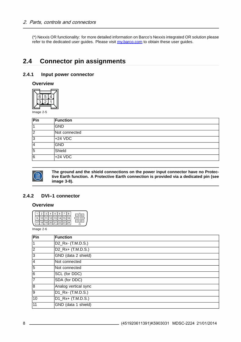
2 Parts controls and connectors
12 Not connected
13 Not connected
14 +5V input (DDC supply) ()
15 GND (cable sense)
16 Hot plug detect ()
17 D0_Rx- (TMDS)
18 D0_Rx+ (TMDS)
19 GND (data 0 shield)
20 Not connected
21 Not connected
22 GND (clock shield)
23 CK_Rx+ (TMDS)
24 CK_Rx- (TMDS)
C1 Analog Red
C2 Analog Green
C3 Analog Blue
C4 Analog horizontal sync
C5 Analog GND return (analog R G B)
() +5 VDC output selectable on either pin 14 or 16 via the OSD menu (+5V plusmn 10 500mA (max))
243 DVI out connector
Overview
Image 2-7
Pin Function
1 D2_Rx- (TMDS)
2 D2_Rx+ (TMDS)
3 GND (data 2 shield)
4 Not connected
5 Not connected
6 SCL (for DDC)
7 SDA (for DDC)
8 Not connected
9 D1_Rx- (TMDS)
10 D1_Rx+ (TMDS)
11 GND (data 1 shield)
12 Not connected
13 Not connected
14 +5V output ()
15 GND (cable sense)
16 Hot plug detect
17 D0_Rx- (TMDS)
(451920611391)K5903031 MDSC-2224 21012014 9
2 Parts controls and connectors
18 D0_Rx+ (TMDS)
19 GND (data 0 shield)
20 Not connected
21 Not connected
22 GND (clock shield)
23 CK_Rx+ (TMDS)
24 CK_Rx- (TMDS)
() +5 VDC output always available (+5V plusmn 10 500mA (max))
244 RS232 connector
Overview
Image 2-8
Pin Function
1 Not connected
2 Rx (driven by host)
3 Tx (driven by display)
4 Not connected
5 Ground
6 Not connected
7 Not connected
8 Not connected
9 Not connected
245 USB connector
Overview
Image 2-9
Pin Function
1 +5 VDC
2 Data mdash
3 Data +
4 GND
10 (451920611391)K5903031 MDSC-2224 21012014
2 Parts controls and connectors
246 Mini USB connector
Overview
12345
Image 2-10
Pin Function
1 +5 VDC
2 Data mdash
3 Data +
X Not connected
4 GND
247 DisplayPort connector
Overview
19 17 15 13 11 9 7 5 3 1
20 18 16 14 12 10 8 6 4 2
Image 2-11
Pin Function
1 ML_Lane 0 (p)
2 GND
3 ML_Lane 0 (n)
4 ML_Lane 1 (p)
5 GND
6 ML_Lane 1 (n)
7 ML_Lane 2 (p)
8 GND
9 ML_Lane 2 (n)
10 ML_Lane 3 (p)
11 GND
12 ML_Lane 3 (n)
13 CONFIG1
14 CONFIG2
15 AUX CH (p)
16 GND
17 AUX CH (n)
18 Hot Plug
19 Return
20 DP_PWR (+33 VDC)
(451920611391)K5903031 MDSC-2224 21012014 11
2 Parts controls and connectors
248 S-Video and S-Video-out connector
Overview
Image 2-12
Pin Function
1 Ground (Y)
2 Ground (C)
3 Luminance (Y)
4 Chroma (C)
SG Shielded Ground
12 (451920611391)K5903031 MDSC-2224 21012014
3 Display installation
3 DISPLAY INSTALLATION
31 VESA mount installationOverviewThe display supports mounting arm amp stands according to the VESA 100 mm standard
CAUTION Use an arm that is approved by VESA
CAUTION Use an arm that can support a weight of least 10 kg (2205 lbs)
The monitor VESA interface has been designed for a safety factor 6 (to support 6 timesthe monitor weight) In the medical system use an arm with suitable safety factor(IEC60601ndash1)
To mount the display to an arm stand1 Attach the arm stand firmly to the panel using the included 4 hexagonal screws (M4 x 25 mm) and the
dented washers Use the included Allen key to fix the screws
Image 3-1
CAUTION The 4 screws included with this display (M4 x 25 mm) can be used for anexternal VESA arm interface with a thickness of up to 5mm
If due to the thickness of the external VESA arm interface (=V) the length of the providedscrews (=L) is not suitable consider the following rule
Lmin = V + 20mm
Lmax = V + 30mm
(451920611391)K5903031 MDSC-2224 21012014 13
3 Display installation
32 Cover removalTo remove the connector compartment cover1 Loosen the screws fixing the connector compartment cover
2 Slide the cover downwards to remove it from the display
1
2 2
1
Image 3-2
33 Video input connection
About video input connectionsThe MDSC-2224 can have multiple different video inputs connected (depending on the display version)Switching between the different inputs can be easily done by pressing the direct access key for this Seethe dedicated section for more info
Futhermore if more than one video source is connected the Picture in Picture (PiP) and Side-by-Side(SbS) functionality becomes available allowing you to view two different video inputs at once Pleaserefer to the dedicated chapter for more info on how to activate and use the PiP and SbS features on yourMDSC-2224
This chapter describes how to connect the different video input types for each version of the MDSC-2224
331 MDSC-2224 LED version
To connect the video inputs1 Connect one or more of the available video source(s) to the corresponding video inputs using the ap-
propriate video cable(s)
4 5 6 7 8
1 2 3
9
Image 3-3
DVI or VGA () 4
DisplayPort 5
14 (451920611391)K5903031 MDSC-2224 21012014
3 Display installation
SDI 1
RGBS 6 7 8 2
RGB (SOG) 6 7 8
YPbPr 7 8 6
CVBS 3
S-Video 9
() PC analog (VGA) input source can be connected to the DVI-I input connector using a DVI-I to VGAadapter The use of an adapter cable of at least 015 m long will allow an easy placement inside the cablecover
332 MDSC-2224 MNA version
To connect the video inputs1 Connect one or more of the available video source(s) to the corresponding video inputs using the ap-
propriate video cable(s)
4 5 6 7 8
1 2
93
Image 3-4
Nexxis 3
DVI or VGA () 4
DisplayPort 5
RGBS 6 7 8 1
YPbPr 7 8 6
CVBS 2
S-Video 9
() PC analog (VGA) input source can be connected to the DVI-I input connector using a DVI-I to VGAadapter The use of an adapter cable of at least 015 m long will allow an easy placement inside the cablecover
(451920611391)K5903031 MDSC-2224 21012014 15
3 Display installation
34 Video output connection
About video output connectionsBeside the video input connections the MDSC-2224 also has video output capabilities allowing you toloop-through certain video inputs connected with the MDSC-2224 to another display projector videorecorder
This chapter describes how to make use of the video output connections available for each version of theMDSC-2224
341 MDSC-2224 LED version
To connect the video outputs1 Connect one or more of the available video sink(s) to the corresponding video outputs using the appro-
priate video cable(s)
4
1 2 3
Image 3-5
SDI 1
CVBS 2
S-Video 3
DVI 4 (to be configured in OSD menu)
342 MDSC-2224 MNA version
To connect the video outputs1 Connect one or more of the available video sink(s) to the corresponding video outputs using the appro-
priate video cable(s)
16 (451920611391)K5903031 MDSC-2224 21012014
3 Display installation
3
1 2
Image 3-6
CVBS 1
S-Video 2
DVI 3 (to be configured in OSD menu)Nexxis 3 (to be configured in OSD menu)
35 Nexxis OROverviewConnecting your MDSC-2224 to Barcorsquos Nexxis OR system allows you to distribute video graphics audioand computer data over the IP network in raw uncompressed format inside the operating room and evenbetween surgical suites
To connect your MDSC-2224 to Barcorsquos Nexxis OR system connect the 10Gb Ethernet interface to yourNexxis switch More info about Nexxis OR and how to configure the MDSC-2224 in your network is avail-able in the dedicated user guides Please visit wwwbarcocom to obtain these user guides
Nexxis OR is only available on the MDSC-2224 MNA version
36 Power supply connection
To connect the power supply1 Connect the supplied external DC power supply unit to the +24 VDC power input of your MDSC-2224
display
2 Plug the other end of the external DC power supply into a grounded power outlet by means of theproper power cord delivered in the packagingNote The ground and the shield connections on the power input connector have no Protective Earth
function A Protective Earth connection is provided via a dedicated pin (see image 3-8)
(451920611391)K5903031 MDSC-2224 21012014 17
3 Display installation
Image 3-7
Protective earth pin1 Earth the MDSC-2224 by connecting the protective earth pin to a grounded outlet by means of an
AWG18 (max 6ft 18m long) wire
1
Image 3-8
37 Cable routing
To route the cables1 For displays mounted to a VESA arm with internal cable routing provisions route all cables through the
cable routing channel then reinstall the connector compartment cover
8a
Image 3-9
18 (451920611391)K5903031 MDSC-2224 21012014
3 Display installation
OrFor all other mounting options remove the cable routing channel expansion clip from the connectorcompartment cover and route all cables through it while reinstalling the cover
8b
Image 3-10
WARNING When the display is assembled in the medical system take care of the fixa-tion of all cables to avoid unwanted detachment
(451920611391)K5903031 MDSC-2224 21012014 19
3 Display installation
20 (451920611391)K5903031 MDSC-2224 21012014
4 Daily operation
4 DAILY OPERATION
41 Keyboard activationdeactivation
To activate the keyboardIn order to avoid unwanted or accidental activation of the OSD keyboard a lockunlock mechanism hasbeen implemented This means that before the OSD keyboard can be used to change any of the settingof the display it needs to be unlocked
1 Swipe a finger from the power button zone to the left for about 12 cm
Image 4-1
As a result the keys will light up and are now available for further actions However if no further actionsare taken within the following 10 seconds the keyboard backlight will dim and the keys will be lockedagain
To deactivate the keyboard1 The keyboard will automatically lock after 10 seconds of inactivity except while navigating the OSD
menu during which it remains unlocked
As a result Its backlight switches off to indicate the keyboard is lockedOrmanually lock the keyboard by sweeping your finger over the bottom right hand side of your display
Image 4-2
(451920611391)K5903031 MDSC-2224 21012014 21
4 Daily operation
Keyboard backlight rsquoAlways onrsquo modeWhen used with keyboard Backlight lsquoAlways onrsquo (factory setting is lsquoOn with touchrsquo) the lock unlock statusof the keyboard cannot be linked to the on off status of the keyboard backlight (the backlight is alwayson in this mode except when in Power Save of Soft Off)
Therefore the keyboard lock status is being signaled by a slow blinking of the keyboard backlight betweenon and off at a rate of one cycle per second The Keyboard will automatically lock after 10 minutes
Keyboard backlight rsquoOn withtouchrsquo (Factory default)
Keyboard backlight rsquoAlways onrsquo(Custom setting)
Keyboard Locked Keyboard backlight is off andremains off while a key is pressed
Keyboard backlight is on andstarts slowly blinking between onand off while key is pressed
Keyboard Unlocked Keyboard backlight is on and dimsslightly while a key is pressed
Keyboard backlight is on and dimsslightly while a key is pressed
Keyboard AUTO-lock Timeout 10 seconds 10 minutes
42 Keyboard backlight
About the keyboard backlightBy default only the stand-by key is visible After keyboard activation (see Keyboard activationdeactiva-tion page 21) the backlight of all keys is switched on for a few seconds When you touch any of thesekeys again while the backlight is on the function of the key is executed If no further action is taken withinthe time-out the keyboard backlight is switched off again
The keyboard backlight auto-dim function can be disabled in the OSD menu so that thekeyboard backlight is always on (Keyboard Backlight)
43 OnOff switching
To switch on your display1 Activate the power supply through the switch located on the external power supply
2 While your display is off press and hold the stand-by key for approximately 3 seconds (or until thekeyboard backlight stops blinking)
To minimize the power consumption also the external power supply has to be switchedoff
To switch off your display1 While your display is switched on unlock the keyboard see Keyboard activationdeactivation page
21
2 Press and hold the stand-by key for approximately 3 seconds (or until the keyboard backlight stopsblinking and switches off)
22 (451920611391)K5903031 MDSC-2224 21012014
4 Daily operation
While pressing the stand-by key to switch off the display the front key illumination willblink
44 Power led statusAbout the the power led statusThe behavior of the power led shows the status of the unit
bull No led visible the status of the unit is hard OFF (the switch of the power supply is OFF)
bull Led is fading between on and off the status of the unit is soft OFF (when pushing the standby buttonthe unit is on or off)
bull Led is full orange the unit is in power save mode (no signal amp power save mode enabled)
bull Led is blinking greenorange the unit is in searching mode (looking for a signal)bull Led is full green the unit has an image on the screen
45 OSD menu activationTo activate the OSD menu1 If not already done so switch on the display by pressing and holding the stand-by key for approxi-
mately 3 seconds
2 Switch on the front key illumination by activating the keyboard (see Keyboard activationdeactivationpage 21)
3 Touch the MenuEnter key
As a result the OSD main menu comes up in the bottom right corner of the screen If no further actionsare taken within the following 30 seconds the OSD menu will disappear again
The time-out of the OSD menu automatic close function can be adjusted or disabled inthe OSD menu (OSD Time-out)
The OSD menu position can be adjusted in the OSD menu (OSD Hor Pos and OSD VertPos)
46 OSD menu navigation
OSD menu structure explainedBelow is on example of how the OSD menu structure looks like
(451920611391)K5903031 MDSC-2224 21012014 23
4 Daily operation
Picture
Brightness 50
Contrast 50
Saturation 30
Profile Factory
Color temperature 6500K
Gamma Native
Sharpness 10
DVI 1280x80060Hz
1 6
5
32 4
Image 4-3
1 Menu
2 Sub-menu
3 Status bar
4 Legenda (shows the functionality associated to each keyboard key)
5 SelectorSlider
6 Item
To navigate through the OSD menu
Image 4-4
bull Press the key to open the OSD menubull Use the or key to scroll to the desired menu page
bull When the desired Menu page is highlighted press the key to select the top menu item that will behighlighted
bull Use the or keys to move to other Menu Items then press the key to select it
bull If the selected menu item is controlled by a slider use the or keys to adjust the item value thenpress the key to confirm
bull If the selected menu item is a multiple choices menu use the or keys to select the desired optionthen press the key to confirm
bull Press again or key to select other Menu items or exit from the Menu page by pressing the key
47 Shortkey functions
About shortkey functionsThe concept of shortkey functions is to present a selection of commonly used functions immediately avail-able without the need to navigate through the OSD Menu
The different available shortkey functions are
24 (451920611391)K5903031 MDSC-2224 21012014
4 Daily operation
bull Main source selectionbull Multi-image configuration
bull Zoom factor selection
bull Brightness adjustment
Unlike the extended keyboard functions (described in next chapter) the shortkey func-tionality is immediately available without the need to first enable this in the OSD menu
When the extended keyboard functionality is enabled all the shortkey functions de-scribed below (except for the brightness adjustment) will no longer be available andwill be replaced by the corresponding extended keyboard functions described in thenext chapter
Overview of shortkeys
1 2 3 4 5
Image 4-5
1 Main source selection
2 Multi-image configuration
3 Zoom factor selection
4 Brightness decrease
5 Brightness increase
471 Main source selection
To quickly select the main source1 Use the Input selection key ( ) to scroll through all the possible input signals to select the main input
source
Available main source options dependent on display model
When the extended keyboard functionality is enabled this shortkey functions will nolonger be available and will be replaced by the corresponding extended keyboard func-tions described in the next chapter
472 Multi-image configuration
To quickly select the multi-image configuration1 Use the PiP selection key ( ) to scroll through all possible configurations of Picture-in-Picture (PiP) and
Side-by-Side (SbS)The different PiPSbS options are- Small PiP 30 of Primary height in top-right corner- Large PiP 50 of Primary height in top-right corner- Side-by-Side Primary and Secondary input of equal height
(451920611391)K5903031 MDSC-2224 21012014 25
4 Daily operation
Only a subset of multi-image configuration settings is available via this shortkey func-tion More multi-image configuration settings can be selected in the OSD menus
When the extended keyboard functionality is enabled this shortkey functions will nolonger be available and will be replaced by the corresponding extended keyboard func-tions described in the next chapter
473 Zoom factor selection
To quickly select the zoom factor1 Use the Image zoom key ( ) to select one of the available zoom factors
When the extended keyboard functionality is enabled this shortkey functions will nolonger be available and will be replaced by the corresponding extended keyboard func-tions described in the next chapter
474 Brightness adjustment
To quickly adjust the brightness1 While no OSD Menu is on the screen press the Brightness decrease ( ) or Brightness increase ( )
keys to adjust the brightness as desired
Brightness
50
Image 4-6
When the extended keyboard functionality is enabled this shortkey functions will re-main available
48 Extended keyboard functions
About extended keyboard functionsThe concept of the extended keyboard is to present a large selection of functions immediately availableto the user without the need to navigate through the OSD Menu
Once enabled through dedicated OSD menu function by simply pressing one of the first 3 keys on the leftthe user is presented with a list of new selections displayed on screen the new choices can be selectedby using each of the key just below the OSD text
If two options are available for one key the first key press will select the upper option a second pressselects the lower option
The different available extended keyboard functions are
26 (451920611391)K5903031 MDSC-2224 21012014
4 Daily operation
bull Main source selectionbull Second source selection
bull Multi-image configuration
bull Color temperature selectionbull Image size selection
bull Zoom factor selection
Unlike the shortkey functions (described before) the extended keyboard functionalitymust be first enabled in the OSD menu before you can make use of it Please refer to thededicated section in this manual for more details on how to enabledisable the extendedkeyboard functions
When the extended keyboard functionality is enabled all the shortkey functions de-scribed in previous chapter (except for the brightness adjustment) will no longer beavailable and will be replaced by the corresponding extended keyboard functions de-scribed below
Overview of extended keyboard
1 2 3
Image 4-7
Main source selection1
Second source selection
2 Multi-image configuration
Color temperature selection
Image size selection3
Zoom factor selection
481 Main source selection
To quickly select the main source1 While no OSD Menu is on the screen press the Input selection key ( ) to bring up the main source
quick selection menu
2 Toggle the available main source options by pressing the key corresponding to the desired optionIf two options are available for one key the first key press will select the upper option a second pressselects the lower optionThe current selection is marked in red
3 Press the stand-by key ( ) to confirm your choice and exit the main source quick selection menu
(451920611391)K5903031 MDSC-2224 21012014 27
4 Daily operation
Main source
VGA
DP
R G B
Y Pb Pr
S-Video
CVBS
DVI
SDI Nexxis 2nd Source
EXIT
Image 4-8
Note Available main source options dependent on display model
482 Second source selection
To quickly select the second source1 While no OSD Menu is on the screen press the Input selection key ( ) to bring up the main source
quick selection menu
2 Press the key to switch to the 2nd source quick selection menu
3 Toggle the available second source options by pressing the key corresponding to the desired optionIf two options are available for one key the first key press will select the upper option a second pressselects the lower optionThe current selection is marked in red
4 Press the stand-by key ( ) to confirm your choice and exit the second source quick selection menu
2nd Source
VGA
DP
R G B
Y Pb Pr
S-Video
CVBS
DVI
SDI Nexxis Main source
EXIT
Image 4-9
Note Available second source options dependent on display model
483 Multi-image configuration
To quickly select the multi-image configuration1 While no OSD Menu is on the screen press the PiP selection key ( ) to bring up the multi-image
configuration quick selection menu
2 Toggle the available multi-image configurations by pressing the key corresponding to the desired optionThe current selection is marked in red
3 Press the stand-by key ( ) to confirm your choice and exit the multi-image configuration quick selectionmenu
28 (451920611391)K5903031 MDSC-2224 21012014
4 Daily operation
Multi image config
Native Aspect Fill Small Large None
EXIT
Image 4-10
484 Common Functions Transfer function selection
To quickly select the transfer function1 While no OSD Menu is on the screen press the Image zoom key ( ) to bring up the common functions
quick selection menu
2 Toggle the available transfer function settings by pressing the key corresponding to the desired optionThe current selection is marked in red
3 Press the stand-by key ( ) to confirm your choice and exit the common functions quick selection menu
Common Functions
ITU 709 6500degK X-Ray Native Aspect Zoom
10
EXIT
Image 4-11
Note Only a subset of transfer function settings is available via this quick selection menu More transferfunction settings can be selected in the OSD menus
485 Common Functions Image size selection
To quickly select the image size1 While no OSD Menu is on the screen press the Image zoom key ( ) to bring up the common functions
quick selection menu
2 Toggle the available image size settings by pressing the key corresponding to the desired optionThe current selection is marked in red
3 Press the stand-by key ( ) to confirm your choice and exit the common functions quick selection menu
Common Functions
ITU 709 6500degK X-Ray Native Aspect Zoom
10
EXIT
Image 4-12
Note Only a subset of image size settings is available via this quick selection menu More image sizesettings can be selected in the OSD menus
(451920611391)K5903031 MDSC-2224 21012014 29
4 Daily operation
486 Common Functions Zoom factor selection
To quickly select the zoom factor1 While no OSD Menu is on the screen press the Image zoom key ( ) to bring up the common functions
quick selection menu
2 Toggle the available zoom factors by repeatedly pressing the key until the desired zoom factor isshown
3 Press the stand-by key ( ) to confirm your choice and exit the common functions quick selection menu
Common Functions
ITU 709 6500degK X-Ray Native Aspect Zoom
10
EXIT
Image 4-13
49 Menu lockingunlocking
To lockunlock the menuThe keyboard can be locked from the Menu to avoid unwanted access to OSD functions When the key-board is LOCKED only the OSD Menu key ( ) and the Stand-by key ( ) are active When the Menu OSDkey is pressed the Menu Locked window appears
1 To unlock the keyboard the following sequence of keys need to be pressed
Each time a key is pressed an asterisk is shown in the square boxes
After pressing the fourth key if the sequence is correct the main OSD menu is activated To unlock thekeyboard permanently the specific OSD function is required
Keyboard lockSequence 5 - 6 - 6 - 3
Image 4-14
30 (451920611391)K5903031 MDSC-2224 21012014
5 Advanced operation
5 ADVANCED OPERATION
51 OSD picture menu
Overview
bull Profile
bull Brightnessbull Contrast
bull Saturationbull Color temperature
bull Gamma
bull Sharpness
511 Profile
About profilesTo select a profile means to load a set of predefined video parameters like Brightness Contrast Satura-tion Input selection (Primary amp Secondary) Multi-image layout selection etc
The user can modify the default video parameters associated to each profile and save the new parameterssetting under the User 1 User 2 or User 3 profile The Factory and X Ray profiles can be temporarymodified but the factory default canrsquot be overwritten and can always be recalled through the recall profilemenu item
The available profiles for your display are
bull Factory
bull X Ray
bull User 1bull User 2
bull User 3
To select a profile1 Bring up the OSD main menu
2 Navigate to the Picture menu
3 Enter the Profile submenu
4 Select one of the available profiles and confirm
512 Brightness
To adjust the brightness level1 Bring up the OSD main menu
2 Navigate to the Picture menu
3 Enter the Brightness submenuThe command bar Brightness is highlighted
4 Set the brightness level as desired and confirm
(451920611391)K5903031 MDSC-2224 21012014 31
5 Advanced operation
The selected brightness is maintained at a constant level by the automatic backlightstabilization function
The brightness level can also be adjusted through a shortkey function
Brightness level is adjusted by controlling the backlight illumination only
513 Contrast
To adjust the contrast level1 Bring up the OSD main menu
2 Navigate to the Picture menu
3 Enter the Contrast submenuThe command bar Contrast is highlighted
4 Set the contrast level as desired and confirm
514 Saturation
To adjust the saturation level1 Bring up the OSD main menu
2 Navigate to the Picture menu
3 Enter the Saturation submenuThe command bar Saturation is highlighted
4 Set the saturation level as desired and confirm
515 Color temperature
About color temperature presetsThe available color temperature presets for your display are
bull 5600Kbull 6500K
bull 7600Kbull 9300K
bull ITU 709
bull Nativebull User
32 (451920611391)K5903031 MDSC-2224 21012014
5 Advanced operation
Factory calibration ndash White point
The White Color points associated with the Color Temperature 5600K 6500K 7600K or9300K are factory calibrated with a consequent reduction of the maximum luminancecompared to Native Color Temperature
Factory calibration ndash Color space
When ITU 709 is selected the White Color point and the RGB color primaries are ad-justed according to the target HDTV sRGB color space defined in the ITU-709 recom-mendation RGB primary calibration is performed within the physical limitation of theLCD panel used
Only in case the User preset has been selected it is possible to get access to the colorregulation commands described hereafter
To select a color temperature preset1 Bring up the OSD main menu
2 Navigate to the Picture menu
3 Enter the Color Temperature submenu
4 Select one of the available color temperature presets and confirmNote If you selected the User color temperature preset a new menu will be displayed allowing you to
manually adjust the gain and offset of red green and blue
516 Gamma
About gamma presetsThe available gamma presets for your display are
bull 18
bull 20
bull 22bull 24
bull Native (no correction curve is applied)bull X-ray (grayscale levels are following closely the DICOM curve)
To select a gamma preset1 Bring up the OSD main menu
2 Navigate to the Picture menu
3 Enter the Gamma submenu
4 Select one of the available gamma presets and confirm
517 Sharpness
To adjust the sharpness level1 Bring up the OSD main menu
2 Navigate to the Picture menu
(451920611391)K5903031 MDSC-2224 21012014 33
5 Advanced operation
3 Enter the Sharpness submenuThe command bar Sharpness is highlighted
4 Set the sharpness level as desired and confirm
52 Picture Advanced menuOverview
bull Black Levelbull Smart Video
bull Image Positionbull Auto Adjustment
bull Phase
bull ClockLine
521 Black Level
About black levelThis command allows to add or subtract an offset to the input video signal (available only on video formats)
To adjust the black level1 Bring up the OSD main menu
2 Navigate to the Picture advanced menu
3 Enter the Black Level submenuThe command bar Black Level is highlighted
4 Set the black level as desired and confirm
522 Smart Video
About Smart VideoThis function allows to reduce the video latency in the monitor if its frame rate is in the range of 50 - 60Hz To achieve a minimum latency select one of the surgical modes
The available Smart Video presets for your display are
bull Diagnostic (best picture quality)bull Surgical (low latency)
bull Surgical 1 (low latency optimized for fast moving images)
To select a Smart Video preset1 Bring up the OSD main menu
2 Navigate to the Picture advanced menu
3 Enter the Smart Video submenu
4 Select one of the available Smart Video presets and confirm
34 (451920611391)K5903031 MDSC-2224 21012014
5 Advanced operation
523 Image Position
This menu item is only available when VGA input is connected
To adjust the image position1 Bring up the OSD main menu
2 Navigate to the Picture advanced menu
3 Enter the Image Position submenuA small OSD menu will be activated indicating the horizontal and vertical image position offset
4 Use the and keys to move the picture up and down
5 Use the and keys to move the picture left and right
6 When finished use the key to exit from the small OSD menu
524 Auto Adjustment
This menu item is only available when VGA input is connected
About auto adjustmentWhen auto adjustment is activated the phase and clock per line parameters are automatically adjusted
To activate auto adjustment1 Bring up the OSD main menu
2 Navigate to the Picture advanced menu
3 Enter the Auto Adjustment submenuThe automatic picture adjustment is activated the phase and clock per line parameters are automati-cally adjusted
525 Phase
This menu item is only available when VGA input is connected
About phaseIf the result of the Auto Adjustment procedure described above isnrsquot satisfactory the Phase can be man-ually adjusted by following this procedure
To manually adjust the phase1 Bring up the OSD main menu
2 Navigate to the Picture advanced menu
3 Enter the Phase submenuThe command bar Phase is highlighted
4 Set the phase as desired and confirm
(451920611391)K5903031 MDSC-2224 21012014 35
5 Advanced operation
526 ClockLine
This menu item is only available when VGA input is connected
About clocklineIf the result of the Auto Adjustment procedure described above isnrsquot satisfactory the ClockLine can bemanually adjusted by following this procedure
To manually adjust the phase1 Bring up the OSD main menu
2 Navigate to the Picture advanced menu
3 Enter the ClockLine submenuThe command bar ClockLine is highlighted
4 Set the clockline as desired and confirm
53 Display Format menu
Overview
bull Main Source (Primary Source)bull Component Mode
bull Zoom
bull Image Sizebull 2nd Picture Mode
bull 2nd Picture Sourcebull 2nd Picture Position
bull Picture Swap
531 Main Source (Primary Source)
About main sourcesThe available main sources for your display are
bull Auto Search
bull Compositebull S-Video
bull Componentbull PC Analog
bull DVI 1bull DVI 2
bull SDI 1
bull SDI 2bull Nexxis
bull DisplayPort
36 (451920611391)K5903031 MDSC-2224 21012014
5 Advanced operation
Available main sources dependent on display model
The main source can also be selected through a shortkey function or via the extendedkeyboard functionality
To select the main source1 Bring up the OSD main menu
2 Navigate to the Display Format menu
3 Enter the Main Source submenu
4 Select one of the available main source and confirmNote If you selected the Auto Search preset the display will automatically detect the connected signal
532 Component Mode
About component modesThe available component modes for your display are
bull YPbPr
bull RGB
To select the component mode1 Bring up the OSD main menu
2 Navigate to the Display Format menu
3 Enter the Component Mode submenu
4 Select one of the available component modes and confirm
533 Zoom
About zoomThe available zoom factors for your display are
bull None
bull 10bull 20
bull 30bull 40
bull 50
The zoom factor can also be selected through a shortkey function or via the extendedkeyboard functionality
To select a zoom factor1 Bring up the OSD main menu
2 Navigate to the Display Format menu
(451920611391)K5903031 MDSC-2224 21012014 37
5 Advanced operation
3 Enter the Zoom submenu
4 Select one of the available zoom factors and confirm
534 Image Size
About image sizeThe available image sizes for your display are
bull Full Screen (fill the screen image aspect-ratio can be altered)
bull Aspect (fill the screen on largest dimension no modification in image aspect-ratio)bull Native (input pixel to LCD pixel mapping no scaling)
In Aspect and Native the image may be displayed with black bars on topbottom orleftright
The image size can also be selected via the extended keyboard functionality
To select the image size1 Bring up the OSD main menu
2 Navigate to the Display Format menu
3 Enter the Image Size submenu
4 Select one of the available image sizes and confirm
535 2nd Picture Mode
About 2nd picture modesThe available 2nd picture modes for your display are
bull Off
bull Small PiP 30 of Primary height in top-right cornerbull Large PiP 50 of Primary height in top-right corner
bull Side-by-Side Primary and Secondary input of equal height
bull SbS Native The 2 images are displayed with input pixel to LCD pixel mapping with image crop ifnecessary
bull SbS Fill Both images scaled to fill half of the screen with image crop if necessary
The 2nd picture mode (multi-image configuration) can also be selected via the extendedkeyboard functionality
To select the 2nd picture mode1 Bring up the OSD main menu
2 Navigate to the Display Format menu
3 Enter the 2nd Picture Mode submenu
4 Select one of the available 2nd picture modes and confirm
38 (451920611391)K5903031 MDSC-2224 21012014
5 Advanced operation
Multi image in Full HD available with any combination of input sources
Multi image in SD video available with any combination of input source except Compos-ite amp S-video
536 2nd Picture Source
About 2nd picture sourcesThe available 2nd picture sources for your display are
bull Auto Searchbull Composite
bull S-Videobull Component
bull PC Analog
bull DVI 1bull DVI 2
bull SDI 1bull SDI 2
bull Nexxisbull DisplayPort
The 2nd picture source can also be selected via the extended keyboard functionality
Independent Transfer Function
Gamma and Color temperature for the 2nd Picture Souce are always set to Native and6500K independently from the Transfer Function applied to the Main Picture SourceFor a perfect visualization of a X-ray image please select the X-ray input signal as Mainpicture and if needed the Video image as 2nd picture
To select the 2nd picture source1 Bring up the OSD main menu
2 Navigate to the Display Format menu
3 Enter the 2nd Picture Source submenu
4 Select one of the available 2nd picture sources and confirm
537 2nd Picture Position
About 2nd picture positionsThe available 2nd picture positions for your display are
bull Top Rightbull Top Left
bull Bottom Rightbull Bottom Left
(451920611391)K5903031 MDSC-2224 21012014 39
5 Advanced operation
To select the 2nd picture position1 Bring up the OSD main menu
2 Navigate to the Display Format menu
3 Enter the 2nd Picture Position submenu
4 Select one of the available 2nd picture positions and confirm
538 Picture Swap
About picture swappingTo swap pictures means to exchange (swap) main and 2nd picture
To swap pictures1 Bring up the OSD main menu
2 Navigate to the Display Format menu
3 Enter the Picture Swap submenu
4 Select the desired setting and confirm
54 Configuration menu
Overview
bull Information
bull Language
bull Failover modebull Extended keyboard
bull OSD settingbull Recall Profile
bull Save Profile
541 Information
About informationThe available information items for your display are
bull Model (commercial type identification)bull Operating Hours (backlight operation hours)
bull Firmware Release (firmware identification)
bull Hardware Version (main board identification)bull Option SDI (SDI module identification)
bull Serial Number ANxxxxxxxxxxxx
To access information1 Bring up the OSD main menu
2 Navigate to the Configuration menu
3 Enter the Information submenuThe different information items are shown
40 (451920611391)K5903031 MDSC-2224 21012014
5 Advanced operation
542 Language
About languagesThe available languages for your display are
bull English
bull Franccedilaisbull Deutsch
bull Espantildeol
bull Italiano
To select the language1 Bring up the OSD main menu
2 Navigate to the Configuration menu
3 Enter the Language submenu
4 Select one of the available languages and confirm
543 Failover mode
About failover modeThis function allows the automatic switch to a defined Backup source when the Main input signal is miss-ing
The display will automatically restore the Main input as soon as the signal is back
The Backup source is the input selected as ldquo2nd Picture Sourcerdquo with ldquo2nd Picture Moderdquo = ldquoOffrdquo
This Main amp Backup combination is stored at the moment the function ldquoFailover moderdquo is set to ldquoEnabledrdquo
Failover Mode is not selectable when either the Main Source or the 2nd Picture Source is set to ldquoAu-tosearchrdquo
Failover mode is automatically disabled when either the Main Source or the 2nd PictureSource is changed A warning message ldquoFailover offrdquo appears on the screen for a fewseconds
Returning to the original Main amp Backup combination will automatically re-enable theFailover feature
For the MNA version only Failover mode will be activated 7 seconds after the Nexxissignal becomes unavailable (delay required to allow a Nexxis layout change)
To enabledisable failover mode1 Bring up the OSD main menu
2 Navigate to the Configuration menu
3 Enter the Failover mode submenu
4 EnableDisable failover mode as desired and confirm
(451920611391)K5903031 MDSC-2224 21012014 41
5 Advanced operation
544 Extended keyboard
About the extended keyboardThe concept of the extended keyboard is to present a large selection of functions immediately availableto the user without the need to navigate through the OSD Menu
Once enabled by simply pressing one of the first 3 keys on the left the user is presented with a list of newselections displayed on screen the new choices can be selected by using each of the key just below theOSD text
If two options are available for one key the first key press will select the upper option a second pressselects the lower option
The different available extended keyboard functions are
bull Main source selection
bull Second source selection
bull Multi-image configurationbull Color temperature selection
bull Image size selectionbull Zoom factor selection
To enabledisable the extended keyboard1 Bring up the OSD main menu
2 Navigate to the Configuration menu
3 Enter the Extended keyboard submenu
4 EnableDisable the extended keyboard as desired and confirm
545 OSD setting
5451 OSD Horizontal Position
To adjust the OSD horizontal position1 Bring up the OSD main menu
2 Navigate to the Configuration menu
3 Enter the OSD setting submenu
4 Select OSD Hor PosThe command bar OSD Hor Pos is highlighted
5 Set the OSD horizontal position as desired and confirm
5452 OSD Vertical Position
To adjust the OSD vertical position1 Bring up the OSD main menu
2 Navigate to the Configuration menu
3 Enter the OSD setting submenu
4 Select OSD Ver PosThe command bar OSD Ver Pos is highlighted
5 Set the OSD vertical position as desired and confirm
42 (451920611391)K5903031 MDSC-2224 21012014
5 Advanced operation
5453 OSD Time-out
About OSD time-outThe available OSD time-out values for your display are
bull 10 Sec
bull 20 Secbull 30 Sec
bull 60 Sec
bull Disabled (=5 minutes)
To adjust the OSD time-out1 Bring up the OSD main menu
2 Navigate to the Configuration menu
3 Enter the OSD setting submenu
4 Select OSD Time-out
5 Select one of the available OSD time-out values and confirm
546 Recall Profile
About recalling profilesTo recall a profile means to restore the default factory settings (Factory and X Ray profiles) or recall theuse defined profiles
The available profiles to recall from your display are
bull Factory
bull X Raybull User 1
bull User 2bull User 3
To recall a profile1 Bring up the OSD main menu
2 Navigate to the Configuration menu
3 Enter the Recall Profile submenu
4 Select one of the available profiles to recall and confirm
547 Save Profile
About saving profilesThe user can modify the default video parameters associated to each profile and save the new parameterssetting under the User 1 User 2 or User 3 profile The Factory and X Ray profiles can be modified butthe factory default canrsquot be overwritten and can always be recalled through the recall profile menu item
The available profiles to save in your display are
bull User 1bull User 2
bull User 3
(451920611391)K5903031 MDSC-2224 21012014 43
5 Advanced operation
To save a profile1 Bring up the OSD main menu
2 Navigate to the Configuration menu
3 Enter the Save Profile submenu
4 Select one of the available profiles to save and confirm
55 System menu
Overview
bull Power on DVI 1
bull Power on DVI 2bull DVI Output
bull Keyboard lock
bull Keyboard backlightbull Power Saving
551 Power on DVI 1
About power on DVI 1This setting allows you to select the pin of DVI port 1 connector on which the +5V DC supply is applied
The available options are
bull Disabled
bull +5V on Pin 14
bull +5V on Pin 16
To select the power on DVI 11 Bring up the OSD main menu
2 Navigate to the System menu
3 Enter the Power on DVI 1 submenu
4 Select one of the available options and confirm
552 Power on DVI 2
About power on DVI 2This setting allows you to select the pin of DVI port 2 connector on which the +5V DC supply is applied
The available options are
bull Disabled
bull +5V on Pin 14bull +5V on Pin 16
To select the power on DVI 21 Bring up the OSD main menu
2 Navigate to the System menu
3 Enter the Power on DVI 2 submenu
44 (451920611391)K5903031 MDSC-2224 21012014
5 Advanced operation
4 Select one of the available options and confirm
553 DVI Output
About DVI outputThis setting allows you to select which digital input to replicate on DVI out
The available options are (depending on display version)
bull DVI 1
bull DVI 2bull Nexxis
bull None
This feature is subject to restrictions in case of Multi-image (PiP SbS)
To select the DVI output1 Bring up the OSD main menu
2 Navigate to the System menu
3 Enter the DVI output submenu
4 Select one of the available options and confirm
554 Keyboard lock
About keyboard lockingThis setting allows you to disable the keyboard functionality and avoid unwanted access to the OSD func-tions
Accessing the OSD menu is only possible after pressing a sequence of keys Please refer to the dedicatedsection for more details (Keyboard lockingunlocking)
To enabledisable keyboard locking1 Bring up the OSD main menu
2 Navigate to the System menu
3 Enter the Keyboard Lock submenu
4 EnableDisable keyboard locking as desired and confirm
555 Keyboard backlight
About the keyboard backlightBy default after lighting up the keyboard backlight will dim again if no further actions are taken within thefollowing 5 seconds However this behavior can be changed so that the keyboard backlight is always on
To adjust the keyboard backlight1 Bring up the OSD main menu
2 Navigate to the System menu
3 Enter the Keyboard Backlight submenu
4 Select one of the available options and confirm
(451920611391)K5903031 MDSC-2224 21012014 45
5 Advanced operation
556 Power Saving
About power savingWhen the active input(s) is (are) missing this setting allows the display to switch off the backlight andenter a low power mode In this status the availability of the selected input is checked periodically
When the unit is in power save mode the unit can exit this power save mode in twocases
1 When a signal is applied on the selected input (or any input in case of auto)
2 By activating the OSD menu see OSD menu activation page 23
To enabledisable power saving1 Bring up the OSD main menu
2 Navigate to the System menu
3 Enter the Power Saving submenu
4 EnableDisable power saving as desired and confirm
46 (451920611391)K5903031 MDSC-2224 21012014
6 Important information
6 IMPORTANT INFORMATION
61 Safety information
General recommendationsRead the safety and operating instructions before operating the device
Retain safety and operating instructions for future reference
Adhere to all warnings on the device and in the operating instructions manual
Follow all instructions for operation and use
Electrical Shock or Fire HazardTo prevent electric shock or fire hazard do not remove cover
No serviceable parts inside Refer servicing to qualified personnel
Do not expose this apparatus to rain or moisture
Type of protection (Electrical)Equipment with external power supply Class I equipment
Degree of safety (flammable anesthetic mixture)Equipment not suitable for use in the presence of a flammable anesthetic mixture with air or with oxygenor nitrous oxide
Non-patient care equipment
bull Equipment primarily for use in a health care facility that is intended for use where contact with a patientis unlikely (no applied part)
bull The equipment may not be used with life support equipmentbull The user is not supposed to touch SIPSOPs and the patient at the same time
Mission critical applicationsWe strongly recommend there is a replacement display immediately available in mission critical applica-tions
Use of Electrical Surgical KnivesProvide as much distance as possible between the electrosurgical generator and other electronic equip-ment (such as monitors) An activated electrosurgical generator may cause interference with them Theinterference can activate the OSD menu of the display and as such disrupt the functionality of the display
Power connection ndash Equipment with external 24 VDC power supply
bull Power requirements The equipment must be powered using the delivered medical approved 24 VDC( ) SELV power supply
bull The medical approved DC ( ) power supply must be powered by the AC mains voltage
bull The power supply is specified as a part of the ME equipment or combination is specified as a MEsystem
bull To avoid the risk of electric shock this equipment must only be connected to a supply mains withprotective earth
bull The equipment should be installed near an easily accessible outlet
bull The equipment is intended for continuous operation
(451920611391)K5903031 MDSC-2224 21012014 47
6 Important information
bull The compliance of this monitor with Medical Safety and EMC requirements has been evaluated usingthe external (optional) Skynet medical power supply model BAR-A159 If a different power supply willbe used further investigation for Safety and EMC requirements have to be performed at system level
Power cords
bull Utilize a UL-listed detachable power cord 3-wire type SJ or equivalent 18 AWG min rated 250 Vmin provided with a hospital-grade type plug 5-15P configuration for 120V application or 6-15P for240V application
bull Do not overload wall outlets and extension cords as this may result in fire or electric shock
bull Mains lead protection (US Power cord) Power cords should be routed so that they are not likely tobe walked upon or pinched by items placed upon or against them paying particular attention to cordsat plugs and receptacles
bull The power supply cord should be replaced by the designated operator only at all timebull Use a power cord that matches the voltage of the power outlet which has been approved and complies
with the safety standard of your particular country
Transient over-voltageIf the device is not used for a long time disconnect it from the AC inlet to avoid damage by transientover-voltage
To fully disengage the power to the device please disconnect the power cord from the AC inlet
ConnectionsAny external connection with other peripherals must follow the requirements of clause 16 of IEC60601-13rd ed or Table BBB201 of IEC 60601-1-1 for the medical electrical systems
Water and moistureThe equipment is IP21 compliant (IPx5 front side only)
The power supply is not approved for IP21 The power supply must be mounted in a flatposition for best resistance to fluids
VentilationDo not cover or block any ventilation openings in the cover of the set When installing the device in acupboard or another closed location heed the necessary space between the set and the sides of thecupboard
Installation
bull Place the equipment on a flat solid and stable surface that can support the weight of at least 3 equip-ments If you use an unstable cart or stand the equipment may fall causing serious injury to a childor adult and serious damage to the equipment
bull Do not allow to climb or rest on the equipment
bull When adjusting the angle of the equipment move it slowly so as to prevent the equipment from movingor slipping off from its stand or arm
bull When the equipment is attached to an arm do not use the equipment as a handle or grip in order tomove the equipment Please refer to the instruction manual of the arm for instructions on how to movethe arm with the equipment
bull Provide full attention to safety during installation periodic maintenance and examination of this equip-ment
48 (451920611391)K5903031 MDSC-2224 21012014
6 Important information
bull Sufficient expertise is required for installing this equipment especially to determine the strength of thewall for withstanding the displayrsquos weight Be sure to entrust the attachment of this equipment to thewall to licensed contractors of Barco and pay adequate attention to safety during the installation andusage
bull Barco is not liable for any damage or injury caused by mishandling or improper installation
General warnings
bull All devices and complete setup must be tested and validated before taking into operation
bull The installer needs to foresee a backup system in case the video falls away
Technical data
bull The monitor is intended for indoor usebull The monitor has been designed to be used in landscape position with a tilt of -10deg (backward) and
+10deg (forward)
bull Power consumption 24VDC 32A maxbull Operating Temperature 10-35degC for performance 0-40degC for safety
bull Operating Humidity 10-90 RH
bull Operating Altitude 3000m maxbull Storage -20 divide +60degC 10 divide 90RH
bull IP Protection IP21 (IPx5 front side only) in vertical positionbull Class I Equipment according to the type of protection against electric shock
bull The monitor is not intended to be sterilized
bull The monitor has not applied parts but the front side of the LCD panel and the plastic enclosure havebeen treated as applied part because considered accidentally touchable by the patient for a time lt1minute
This apparatus conforms toMedical Equipment
3rd edition
ANSIAAMI ES 60601-1 3rd edition 2005 EN 60601 3rd edition 2006 IEC 60601-1 3rd edition (2005)CE (MDD) Class I essential requirements of MDD 9342EEC version 2007 (in effect as of March 2010)CANCSA-C222 No 606011-08
EMC
IEC EN 60601-1-2 2007
EN 55011 CISPR11 (MDSC-2224-MNA Class A MDSC-2224-LED Class B)
National Scandinavian Deviations for CL 172Finland Laite on liitettaumlvauml suojamaadoituskoskettimilla varustettuun pistorasiaan
Norway Apparatet maring tilkoples jordet stikkontakt
Sweden Apparaten skall anslutas till jordat uttag
62 Environmental informationDisposal InformationWaste Electrical and Electronic Equipment
(451920611391)K5903031 MDSC-2224 21012014 49
6 Important information
This symbol on the product indicates that under the European Directive 201219EU governingwaste from electrical and electronic equipment this product must not be disposed of with other municipalwaste Please dispose of your waste equipment by handing it over to a designated collection point for therecycling of waste electrical and electronic equipment To prevent possible harm to the environment orhuman health from uncontrolled waste disposal please separate these items from other types of wasteand recycle them responsibly to promote the sustainable reuse of material resources
For more information about recycling of this product please contact your local city office or your municipalwaste disposal service
For details please visit the Barco website at httpwwwbarcocomenAboutBarcoweee
Turkey RoHS compliance
Tuumlrkiye Cumhuriyeti AEEE Youmlnetmeliğine Uygundur
[Republic of Turkey In conformity with the WEEE Regulation]
中国大陆 ROHS (Chinese Mainland RoHS)根据中国大陆《电子信息产品污染控制管理办法》(也称为中国大 陆RoHS) 以下部分列出了Barco 产品中可能包含的有毒和 或有 害物质的名称和含量中国大陆RoHS 指令包含在中国信息产业部 MCV 标准ldquo 电子信息产品中有毒物质的限量要求 中
According to the China Administration on Control of Pollution Caused by Electronic Information Products(Also called RoHS of Chinese Mainland) the table below lists the names and contents of toxic andorhazardous substances that Barcorsquos product may contain The RoHS of Chinese Mainland is included inthe MCV standard of the Ministry of Information Industry of China in the section Limit Requirements oftoxic substances in Electronic Information Products
零件项目(名称)
Component name
有毒有害物质或元素
Hazardous substances and elements铅Pb
汞
Hg
镉Cd
六价铬Cr6+
多溴联苯
PBB
多溴二苯醚PBDE
印制电路配件
Printed Circuit Assemblies
X O O O O O
液晶面板
LCD panel
X O O O O O
外接电(线)缆External Cables
X O O O O O
內部线路Internal wiring
O O O O O O
金属外壳
Metal enclosure
O O O O O O
塑胶外壳
Plastic enclosure
O O O O O O
散热片(器)
Heatsinks
O O O O O O
风扇
Fan
O O O O O O
50 (451920611391)K5903031 MDSC-2224 21012014
6 Important information
零件项目(名称)
Component name
有毒有害物质或元素
Hazardous substances and elements铅Pb
汞
Hg
镉Cd
六价铬Cr6+
多溴联苯
PBB
多溴二苯醚PBDE
电源供应器
Power Supply Unit
X O O O O O
文件说明书Paper Manuals
O O O O O O
光盘说明书CD manual
O O O O O O
O 表示该有毒有害物质在该部件所有均质材料中的含量均在 SJT 11363-2006 标准规定的限量要求以下
O Indicates that this toxic or hazardous substance contained in all of the homogeneous materials forthis part is below the limit requirement in SJT11363-2006X 表示该有毒有害物质至少在该部件的某一均质材料中的含量超出 SJT 11363-2006 标准规定的限量要求
X Indicates that this toxic or hazardous substance contained in at least one of the homogeneousmaterials used for this part is above the limit requirement in SJT11363-2006
在中国大陆销售的相应电子信息产品(EIP)都必须遵照中国大陆《电子信息产品污染控制标识要求》标准贴上环保使用期限(EFUP)标签Barco产品所采用的EFUP标签(请参阅实例徽标内部的编号使用于制定产品)基于中国大陆的《电子信息产品环保使用期限通则》标准
All Electronic Information Products (EIP) that are sold within Chinese Mainland must comply with theldquoElectronic Information Products Pollution Control Labeling Standardrdquo of Chinese Mainland marked withthe Environmental Friendly Use Period (EFUP) logo The number inside the EFUP logo that Barco uses(please refer to the photo) is based on the ldquoStandard of Electronic Information Products EnvironmentalFriendly Use Periodrdquo of Chinese Mainland
Image 6-1
RoHSDirective 201165EC on the restriction of certain hazardous substances in electrical and electronic equip-ment
According to what declared by our components suppliers this product is RoHS compliant
63 Biological hazard and returns
OverviewThe structure and the specifications of this device as well as the materials used for manufacturing makesit easy to wipe and clean and therefore suitable to be used for various applications in hospitals and othermedical environments where procedures for frequent cleaning are specified
However normal use shall exclude biological contaminated environments to prevent spreading of infec-tions
Therefore use of this device in such environments is at the exclusive risk of Customer In case this deviceis used where potential biological contamination cannot be excluded
(451920611391)K5903031 MDSC-2224 21012014 51
6 Important information
Customer shall implement the decontamination process as defined in the latest edition of the ANSIAAMIST35 standard on each single failed Product that is returned for servicing repair reworking or failureinvestigation to Seller (or to the Authorized Service Provider) At least one adhesive yellow label shall beattached on the top site of the package of returned Product and accompanied by a declaration statementproving the Product has been successfully decontaminated
Returned Products that are not provided with such external decontamination label andor whenever suchdeclaration is missing can be rejected by Seller (or by the Authorized Service Provider) and shipped backat Customer expenses
64 Regulatory compliance information
Indications for useThis device is intended to be used in operation rooms to display images from endoscopic cameras roomand boom cameras ultrasound cardiology PACS anesthesiology and patient information It is not in-tended for diagnosis
FCC Class B (valid for MDSC-2224 LED version)This device complies with Part 15 of the FCC Rules Operation is subject to the following two conditions(1) this device may not cause harmful interference and (2) this device must accept any interference re-ceived including interference that may cause undesired operation
This equipment has been tested and found to comply with the limits for a Class B digital device pursuantto Part 15 of the FCC Rules These limits are designed to provide reasonable protection against harmfulinterference in a residential installation This equipment generates uses and can radiate radio frequencyenergy and if not installed and used in accordance with the instructions may cause harmful interferenceto radio communications However there is no guarantee that interference will not occur in a particularinstallation If this equipment does cause harmful interference to radio or television reception which canbe determined by turning the equipment off and on the user is encouraged to try to correct the interferenceby one or more of the following measures
bull Reorient or relocate the receiving antennabull Increase the separation between the equipment and receiver
bull Connect the equipment into an outlet on a circuit different from that to which the receiver is connectedbull Consult the dealer or an experienced radioTV technician for help
FCC Class A (valid for MDSC-2224 MNA version)This equipment has been tested and found to comply with the limits of a class A digital device pursuantto Part 15 of the FCC rules These limits are designed to provide reasonable protection against harmfulinterference when the equipment is operated in a commercial environment This equipment generatesuses and can radiate radio frequency energy and if not installed and used in accordance with the instruc-tion manual may cause harmful interference to radio communications Operation of this equipment in aresidential area is likely to cause harmful interference in which case the user will be required to correctthe interference at his own expense
Canadian noticeThis ISM device complies with Canadian ICES-001
Cet appareil ISM est conforme agrave la norme NMB-001 du Canada
52 (451920611391)K5903031 MDSC-2224 21012014
6 Important information
65 Cleaning and disinfection
Instructions
bull Be sure to unplug the power cord from the mains when cleaning your LCD monitor
bull Take care not to scratch the front surface with any hard or abrasive materialbull Dust finger marks grease etc can be removed with a soft damp cloth (a small amount of mild deter-
gent can be used on the damp cloth)
bull Wipe off water drop immediately
Possible cleaning solutions
bull 70 percent isopropyl alcoholbull 16 percent aqueous ammonia
bull Cidexreg (24 percent glutaraldehyde solution)
bull Sodium hypochlorite (bleach) 10 percentbull ldquoGreen soaprdquo (USP)
bull 05 percent Chiorhexidine in 70 percent isopropyl alcoholbull Like Cleansafereg optical cleaning liquid
66 Explanation of symbols
Symbols on the deviceOn the device or power supply you may find the following symbols (nonrestrictive list)
Indicates the device meets the requirements of the applicable EC directives
Indicates compliance with Part 15 of the FCC rules (Class A or Class B)
Indicates the device is approved according to the UL Recognition regulations
Indicates the device is approved according to the UL Demko regulations
Indicates the device is approved according to the CCC regulations
Indicates the device is approved according to the VCCI regulations
Indicates the device is approved according to the KC regulations
Indicates the device is approved according to the BSMI regulations
(451920611391)K5903031 MDSC-2224 21012014 53
6 Important information
Indicates the USB connectors on the device
Indicates the DisplayPort connectors on the device
Indicates the manufacturing date
Indicates the temperature limitations1 for the device to safely operate within specs
Indicates the device serial no
Warning dangerous voltage
Caution
Consult the operating instructions
Indicates this device must not be thrown in the trash but must be recycledaccording to the European WEEE (Waste Electrical and Electronic Equipment)directive
Indicates Direct Current (DC)
Indicates Alternating Current (AC)
Stand-by
67 Legal disclaimer
Disclaimer noticeAlthough every attempt has been made to achieve technical accuracy in this document we assume noresponsibility for errors that may be found Our goal is to provide you with the most accurate and usabledocumentation possible if you discover errors please let us know
Barco software products are the property of Barco They are distributed under copyright by Barco NV orBarco Inc for use only under the specific terms of a software license agreement between Barco NV orBarco Inc and the licensee No other use duplication or disclosure of a Barco software product in anyform is authorized
1 Values for xx and yy can be found in the technical specifications paragraph
54 (451920611391)K5903031 MDSC-2224 21012014
6 Important information
The specifications of Barco products are subject to change without notice
TrademarksAll trademarks and registered trademarks are property of their respective owners
Copyright noticeThis document is copyrighted All rights are reserved Neither this document nor any part of it maybe reproduced or copied in any form or by any means - graphical electronic or mechanical includingphotocopying taping or information storage and retrieval systems - without written permission of Barco
copy 2013 Barco NV All rights reserved
68 Technical specifications
OverviewScreen technology TFT AM LCD
Active screen size (diagonal) 611 mm (241)
Active screen size (H x V) 518 x 324 mm (204 x 127)
Aspect ratio (HV) 1610
Resolution W-UXGA (1920 x 1200)
Pixel pitch 0270 mm
Color imaging Yes
Color support 1073 million
Viewing angle (H V) 178deg
Maximum luminance 350 cdmsup2 (typical)
Contrast ratio 10001
Response time (average Grayto Gray)
6 ms (typ)
Housing color White
DVI-I Single Link (digital amp analog ndash HDMI video support with HDCP)
DisplayPort (VESA std 11a)
RGBS
VGA (only computer VESA signals accepted)
S-video
Composite video
Component video
SDIHD-SDI3GSDI
Video input signals
Nexxis fiber optic input
DVI
CVBS
S-video
Video output signals
SDI
Power source requirementsfor external power supply(nominal)
100-250V
LED version 24VDC 23AmaxPower source requirements fordisplay power input MNA version 24VDC 32Amax
(451920611391)K5903031 MDSC-2224 21012014 55
6 Important information
LED version 65WPower consumption
MNA version 85W
Power save mode Yes
Dot clock 165 MHz max (DVI)
OSD languages English French German Spanish Italian
Display dimensions wo stand(W x H x D)
5954 x 414 x 84 mm (2344 x 163 x 331 in)
Power Supply dimensions (Wx H x D)
210 x 103 x 52 mm (827 x 406 x 205 in)
Dimensions packaged (W x Hx D)
685 x 570 x 170 mm (2697 x 2244 x 669 in)
Net weight display wo stand 79 kg (174 lbs) (95 kg (209 lbs) incl power supply and accessories)
Net weight power supply 15 kg (331 lbs)
Net weight packaged wostand
120 kg (265 lbs)
Power supply DC output cablelength
25 m (82 ft)
Mounting standard VESA (100 mm)
Screen protection Protective non-reflective PMMA cover
Recommended modalities Endoscopy Laparoscopy PACS PM US CT MR
Certifications ANSIAAMI ES 60601-1 3rd edition 2005 EN 60601 3rd edition2006 IEC 60601-1 3rd edition (2005) CE (MDD) Class I essentialrequirements of MDD 9342EEC version 2007 (in effect as of March2010) CANCSA-C222 No 606011-08 IEC EN 60601-1-2 2007EN 55011 CISPR11 (MDSC-2224-MNA Class A MDSC-2224 LEDClass B) FCC (A or B depending on model) RoHs compliant IP21(IPx5 front side only)User Guide
Video cable (DVI Dual Link)
Mains cables (European (CEBECKEMA) USA (ULCSA))
Supplied accessories
External power supply
Optional accessories Barco stand (K9302032A)
Power extension cable 10m (K3495066)
Power extension cable 30m (K3495068)Warranty 3 years
Operating temperature 10-35degC for performance 0-40degC for safety
Storage temperature -20 divide +60degC
Operating humidity 10 divide 90 (non-condensing)
Storage humidity 10 divide 90 (non-condensing)
Operating altitude 3000 m max
Storage altitude 12000 m max
Timings DVI-VGAItem Name Pixel x Line Format Hor Fr
(kHz)Vert Fr(Hz)
HorTotal
VertTotal
DVI VGA
1 480i 720 x 487 NTSC 15734 5994 Y N
2 480p59 720 x 480 480p 3147 5994 Y N
3 480p60 720 x 480 480p 315 60 Y N
4 576i 720 x 576 PAL I 15625 50 Y N
5 576p 720 x 576 576p 3125 50 Y N
56 (451920611391)K5903031 MDSC-2224 21012014
6 Important information
Item Name Pixel x Line Format Hor Fr(kHz)
Vert Fr(Hz)
HorTotal
VertTotal
DVI VGA
6 720p29 1280 x 720 720p 2248 2997 Y N
7 720p30 1280 x 720 720p 225 30 Y N
8 720p50 1280 x 720 720p 375 50 Y N
9 720p59 1280 x 720 720p 4496 5994 Y N
10 720p60 1280 x 720 720p 45 60 Y N
11 1080i25 1920 x 1080 1080i 2813 50 Y N
12 1080i29 1920 x 1080 1080i 3372 5994 Y N
13 1080i30 1920 x 1080 1080i 3375 60 Y N
14 1080p29 1920 x 1080 1080p 3372 2997 Y N
15 1080p30 1920 x 1080 1080p 3375 30 Y N
16 1080p50 1920 x 1080 1080p 5625 50 Y N
17 1080p59 1920 x 1080 1080p 67433 5994 Y N
18 1080p60 1920 x 1080 1080p 675 60 Y N
19 DMT0660 604 x 480 VGA 315 60 Y Y
20 DMT0672 604 x 480 VGA 3786 72808 Y Y
21 DMT0675 604 x 480 VGA 375 75 Y Y
22 DMT0685 604 x 480 VGA 43269 85008 Y Y
23 DMT0856 800 x 600 SVGA 3516 5625 Y Y
24 DMT0860 800 x 600 SVGA 3788 6032 Y Y
25 DMT0872 800 x 600 SVGA 4808 7219 Y Y
26 DMT0875 800 x 600 SVGA 46875 75 Y Y
27 DMT0885 800 x 600 SVGA 5374 85061 Y Y
28 DMT1060 1027 x 768 XGA 484 60 Y Y
29 DMT1070 1024 x 768 XGA 564 70 Y(Diagmode)2
Y (Diagmode) 2
30 DMT1075 1024 x 768 XGA 60 75 Y Y
31 DMT1085 1024 x 768 XGA 687 85 Y Y
32 DMT1175 1152 x 864 XGA+ 675 75 Y Y
33 DMT1260G 1280 x 1024 SXGA 64 60 Y Y
34 DMT1275G 1280 x 1024 SXGA 79976 75025 Y Y
35 DMT1285G 1280 x 1024 SXGA 911 85 Y Y
36 DMT1660 1600 x 1200 UXGA 75 60 Y Y
37 CVR1460 1400 x 1050 SXGA+ 64744 59948 Y Y
38 CVT1460 1400 x 1050 SXGA+(VESA)
6532 5998 Y Y
39 CVR1660D 1680 x 1050 WSXGA+1 6467 5988 Y Y
40 CVT1660D 1680 x 1050 WSXGA+2 6529 5995 Y Y
41 CVT 1920 x 1200 WUXGA1 74038 5995 Y Y
42 IBM 640 x 350 315 70 800 449 Y(Diagmode)2
N
43 VESA 640 x 350 379 85 832 446 Y Y
44 VESA 640 x 400 248 563 848 440 N Y
2 OSD Smart Video set to ldquoDiagnosticrdquo
(451920611391)K5903031 MDSC-2224 21012014 57
6 Important information
Item Name Pixel x Line Format Hor Fr(kHz)
Vert Fr(Hz)
HorTotal
VertTotal
DVI VGA
45 IBM 640 x 400 315 700 800 449 Y(Diagmode)2
N
46 VESA 640 x 400 379 850 832 446 Y Y
Timings Comp - SOGItem Name Pixel x Line Format Hor Fr
(kHz)Vert Fr(Hz)
HorTotal
VertTotal
SOG RGBS YPbPr
1 480i 720 x 487 NTSC 15734 5994 Y Y
2 480p59 720 x 480 480p 3147 5994 Y Y
3 480p60 720 x 480 480p 315 60 Y Y
4 576i 720 x 576 PAL I 15625 50 Y Y
5 576p 720 x 576 576p 3125 50 Y Y
8 720p50 1280 x 720 720p 375 50 Y Y
9 720p59 1280 x 720 720p 4496 5994 Y Y
10 720p60 1280 x 720 720p 45 60 Y Y
11 1080i25 1920 x 1080 1080i 2813 50 Y Y
12 1080i29 1920 x 1080 1080i 3372 5994 Y Y
13 1080i30 1920 x 1080 1080i 3375 60 Y Y
14 1080p29 1920 x 1080 1080p 3372 2997 Y Y
15 1080p30 1920 x 1080 1080p 3375 30 Y Y
16 1080p50 1920 x 1080 1080p 5625 50 Y Y
17 1080p59 1920 x 1080 1080p 67433 5994 Y Y
18 1080p60 1920 x 1080 1080p 675 60 Y Y
Timings SDIItem Name Pixel x Line Format Hor Fr
(kHz)Vert Fr(Hz)
HorTotal
VertTotal
SDI(Ypb)
RGBS YPbPr
1 480i 720 x 487 NTSC 15734 5994 Y Y
4 576i 720 x 576 PAL I 15625 50 Y Y
8 720p50 1280 x 720 720p 375 50 Y Y
9 720p59 1280 x 720 720p 4496 5994 Y Y
10 720p60 1280 x 720 720p 45 60 Y Y
11 1080i25 1920 x 1080 1080i 2813 50 Y Y
12 1080i29 1920 x 1080 1080i 3372 5994 Y Y
13 1080i30 1920 x 1080 1080i 3375 60 Y Y
14 1080p29 1920 x 1080 1080p 3372 2997 Y Y
15 1080p30 1920 x 1080 1080p 3375 30 Y Y
16 1080p50 1920 x 1080 1080p 5625 50 Y Y
17 1080p59 1920 x 1080 1080p 67433 5994 Y Y
18 1080p60 1920 x 1080 1080p 675 60 Y Y
SDI Standard ComplianceSMPTE 425M (level A) SMPTE 424M SMPTE 292M SMPTE 296M ITU-R BT656 ITU-R BT601
58 (451920611391)K5903031 MDSC-2224 21012014
6 Important information
SDI Video SamplingY Cb Cr 422
Dimensions5954 mm (2344rdquo) 84 mm (331rdquo)
414
mm
(16
3rdquo)
100
mm
(3
94rdquo)
100 mm (394rdquo)
Image 6-2
69 Open source license information
Open source license informationOpen source license usage
(451920611391)K5903031 MDSC-2224 21012014 59
6 Important information
This product contains software components released under an Open Source license A copy of the sourcecode is available on request by contacting your Barco customer support representative
EACH SEPARATE OPEN SOURCE SOFTWARE COMPONENT AND ANY RELATED DOCUMENTA-TION ARE PROVIDED AS IS WITHOUT EXPRESS OR IMPLIED WARRANTY INCLUDING BUT NOTLIMITED TO THE IMPLIED WARRANTIES OF MERCHANTABILITY AND FITNESS FOR A PARTICU-LAR PURPOSE IN NO EVENT SHALL THE COPYRIGHTHOLDER OR ANY OTHER CONTRIBUTORBE LIABLE FOR DIRECT INCIDENTAL OR CONSEQUENTIAL DAMAGES EVEN IF ADVISED OF THEPOSSIBILITY OF SUCH DAMAGES MORE INFORMATIONDETAILS IS TO BE FOUND IN EACH SPE-CIFIC OPEN SOURCE LICENSE
Copyright on each Open Source Software component belongs to the respective initial copyright holdereach additional contributor andor their respective assignee(s) as may be identified in the respective doc-umentation source code README file or otherwise You shall not remove or obscure or otherwise alterthe respective copyrights
You acknowledge living up to the conditions of each separate Open Source Software license
A list of the Open Source Software components used is available in the applicable EULA through the(customer section of the) Barco website or through other (online) means
60 (451920611391)K5903031 MDSC-2224 21012014

2 Parts controls and connectors
248 S-Video and S-Video-out connector
Overview
Image 2-12
Pin Function
1 Ground (Y)
2 Ground (C)
3 Luminance (Y)
4 Chroma (C)
SG Shielded Ground
12 (451920611391)K5903031 MDSC-2224 21012014
3 Display installation
3 DISPLAY INSTALLATION
31 VESA mount installationOverviewThe display supports mounting arm amp stands according to the VESA 100 mm standard
CAUTION Use an arm that is approved by VESA
CAUTION Use an arm that can support a weight of least 10 kg (2205 lbs)
The monitor VESA interface has been designed for a safety factor 6 (to support 6 timesthe monitor weight) In the medical system use an arm with suitable safety factor(IEC60601ndash1)
To mount the display to an arm stand1 Attach the arm stand firmly to the panel using the included 4 hexagonal screws (M4 x 25 mm) and the
dented washers Use the included Allen key to fix the screws
Image 3-1
CAUTION The 4 screws included with this display (M4 x 25 mm) can be used for anexternal VESA arm interface with a thickness of up to 5mm
If due to the thickness of the external VESA arm interface (=V) the length of the providedscrews (=L) is not suitable consider the following rule
Lmin = V + 20mm
Lmax = V + 30mm
(451920611391)K5903031 MDSC-2224 21012014 13
3 Display installation
32 Cover removalTo remove the connector compartment cover1 Loosen the screws fixing the connector compartment cover
2 Slide the cover downwards to remove it from the display
1
2 2
1
Image 3-2
33 Video input connection
About video input connectionsThe MDSC-2224 can have multiple different video inputs connected (depending on the display version)Switching between the different inputs can be easily done by pressing the direct access key for this Seethe dedicated section for more info
Futhermore if more than one video source is connected the Picture in Picture (PiP) and Side-by-Side(SbS) functionality becomes available allowing you to view two different video inputs at once Pleaserefer to the dedicated chapter for more info on how to activate and use the PiP and SbS features on yourMDSC-2224
This chapter describes how to connect the different video input types for each version of the MDSC-2224
331 MDSC-2224 LED version
To connect the video inputs1 Connect one or more of the available video source(s) to the corresponding video inputs using the ap-
propriate video cable(s)
4 5 6 7 8
1 2 3
9
Image 3-3
DVI or VGA () 4
DisplayPort 5
14 (451920611391)K5903031 MDSC-2224 21012014
3 Display installation
SDI 1
RGBS 6 7 8 2
RGB (SOG) 6 7 8
YPbPr 7 8 6
CVBS 3
S-Video 9
() PC analog (VGA) input source can be connected to the DVI-I input connector using a DVI-I to VGAadapter The use of an adapter cable of at least 015 m long will allow an easy placement inside the cablecover
332 MDSC-2224 MNA version
To connect the video inputs1 Connect one or more of the available video source(s) to the corresponding video inputs using the ap-
propriate video cable(s)
4 5 6 7 8
1 2
93
Image 3-4
Nexxis 3
DVI or VGA () 4
DisplayPort 5
RGBS 6 7 8 1
YPbPr 7 8 6
CVBS 2
S-Video 9
() PC analog (VGA) input source can be connected to the DVI-I input connector using a DVI-I to VGAadapter The use of an adapter cable of at least 015 m long will allow an easy placement inside the cablecover
(451920611391)K5903031 MDSC-2224 21012014 15
3 Display installation
34 Video output connection
About video output connectionsBeside the video input connections the MDSC-2224 also has video output capabilities allowing you toloop-through certain video inputs connected with the MDSC-2224 to another display projector videorecorder
This chapter describes how to make use of the video output connections available for each version of theMDSC-2224
341 MDSC-2224 LED version
To connect the video outputs1 Connect one or more of the available video sink(s) to the corresponding video outputs using the appro-
priate video cable(s)
4
1 2 3
Image 3-5
SDI 1
CVBS 2
S-Video 3
DVI 4 (to be configured in OSD menu)
342 MDSC-2224 MNA version
To connect the video outputs1 Connect one or more of the available video sink(s) to the corresponding video outputs using the appro-
priate video cable(s)
16 (451920611391)K5903031 MDSC-2224 21012014
3 Display installation
3
1 2
Image 3-6
CVBS 1
S-Video 2
DVI 3 (to be configured in OSD menu)Nexxis 3 (to be configured in OSD menu)
35 Nexxis OROverviewConnecting your MDSC-2224 to Barcorsquos Nexxis OR system allows you to distribute video graphics audioand computer data over the IP network in raw uncompressed format inside the operating room and evenbetween surgical suites
To connect your MDSC-2224 to Barcorsquos Nexxis OR system connect the 10Gb Ethernet interface to yourNexxis switch More info about Nexxis OR and how to configure the MDSC-2224 in your network is avail-able in the dedicated user guides Please visit wwwbarcocom to obtain these user guides
Nexxis OR is only available on the MDSC-2224 MNA version
36 Power supply connection
To connect the power supply1 Connect the supplied external DC power supply unit to the +24 VDC power input of your MDSC-2224
display
2 Plug the other end of the external DC power supply into a grounded power outlet by means of theproper power cord delivered in the packagingNote The ground and the shield connections on the power input connector have no Protective Earth
function A Protective Earth connection is provided via a dedicated pin (see image 3-8)
(451920611391)K5903031 MDSC-2224 21012014 17
3 Display installation
Image 3-7
Protective earth pin1 Earth the MDSC-2224 by connecting the protective earth pin to a grounded outlet by means of an
AWG18 (max 6ft 18m long) wire
1
Image 3-8
37 Cable routing
To route the cables1 For displays mounted to a VESA arm with internal cable routing provisions route all cables through the
cable routing channel then reinstall the connector compartment cover
8a
Image 3-9
18 (451920611391)K5903031 MDSC-2224 21012014
3 Display installation
OrFor all other mounting options remove the cable routing channel expansion clip from the connectorcompartment cover and route all cables through it while reinstalling the cover
8b
Image 3-10
WARNING When the display is assembled in the medical system take care of the fixa-tion of all cables to avoid unwanted detachment
(451920611391)K5903031 MDSC-2224 21012014 19
3 Display installation
20 (451920611391)K5903031 MDSC-2224 21012014
4 Daily operation
4 DAILY OPERATION
41 Keyboard activationdeactivation
To activate the keyboardIn order to avoid unwanted or accidental activation of the OSD keyboard a lockunlock mechanism hasbeen implemented This means that before the OSD keyboard can be used to change any of the settingof the display it needs to be unlocked
1 Swipe a finger from the power button zone to the left for about 12 cm
Image 4-1
As a result the keys will light up and are now available for further actions However if no further actionsare taken within the following 10 seconds the keyboard backlight will dim and the keys will be lockedagain
To deactivate the keyboard1 The keyboard will automatically lock after 10 seconds of inactivity except while navigating the OSD
menu during which it remains unlocked
As a result Its backlight switches off to indicate the keyboard is lockedOrmanually lock the keyboard by sweeping your finger over the bottom right hand side of your display
Image 4-2
(451920611391)K5903031 MDSC-2224 21012014 21
4 Daily operation
Keyboard backlight rsquoAlways onrsquo modeWhen used with keyboard Backlight lsquoAlways onrsquo (factory setting is lsquoOn with touchrsquo) the lock unlock statusof the keyboard cannot be linked to the on off status of the keyboard backlight (the backlight is alwayson in this mode except when in Power Save of Soft Off)
Therefore the keyboard lock status is being signaled by a slow blinking of the keyboard backlight betweenon and off at a rate of one cycle per second The Keyboard will automatically lock after 10 minutes
Keyboard backlight rsquoOn withtouchrsquo (Factory default)
Keyboard backlight rsquoAlways onrsquo(Custom setting)
Keyboard Locked Keyboard backlight is off andremains off while a key is pressed
Keyboard backlight is on andstarts slowly blinking between onand off while key is pressed
Keyboard Unlocked Keyboard backlight is on and dimsslightly while a key is pressed
Keyboard backlight is on and dimsslightly while a key is pressed
Keyboard AUTO-lock Timeout 10 seconds 10 minutes
42 Keyboard backlight
About the keyboard backlightBy default only the stand-by key is visible After keyboard activation (see Keyboard activationdeactiva-tion page 21) the backlight of all keys is switched on for a few seconds When you touch any of thesekeys again while the backlight is on the function of the key is executed If no further action is taken withinthe time-out the keyboard backlight is switched off again
The keyboard backlight auto-dim function can be disabled in the OSD menu so that thekeyboard backlight is always on (Keyboard Backlight)
43 OnOff switching
To switch on your display1 Activate the power supply through the switch located on the external power supply
2 While your display is off press and hold the stand-by key for approximately 3 seconds (or until thekeyboard backlight stops blinking)
To minimize the power consumption also the external power supply has to be switchedoff
To switch off your display1 While your display is switched on unlock the keyboard see Keyboard activationdeactivation page
21
2 Press and hold the stand-by key for approximately 3 seconds (or until the keyboard backlight stopsblinking and switches off)
22 (451920611391)K5903031 MDSC-2224 21012014
4 Daily operation
While pressing the stand-by key to switch off the display the front key illumination willblink
44 Power led statusAbout the the power led statusThe behavior of the power led shows the status of the unit
bull No led visible the status of the unit is hard OFF (the switch of the power supply is OFF)
bull Led is fading between on and off the status of the unit is soft OFF (when pushing the standby buttonthe unit is on or off)
bull Led is full orange the unit is in power save mode (no signal amp power save mode enabled)
bull Led is blinking greenorange the unit is in searching mode (looking for a signal)bull Led is full green the unit has an image on the screen
45 OSD menu activationTo activate the OSD menu1 If not already done so switch on the display by pressing and holding the stand-by key for approxi-
mately 3 seconds
2 Switch on the front key illumination by activating the keyboard (see Keyboard activationdeactivationpage 21)
3 Touch the MenuEnter key
As a result the OSD main menu comes up in the bottom right corner of the screen If no further actionsare taken within the following 30 seconds the OSD menu will disappear again
The time-out of the OSD menu automatic close function can be adjusted or disabled inthe OSD menu (OSD Time-out)
The OSD menu position can be adjusted in the OSD menu (OSD Hor Pos and OSD VertPos)
46 OSD menu navigation
OSD menu structure explainedBelow is on example of how the OSD menu structure looks like
(451920611391)K5903031 MDSC-2224 21012014 23
4 Daily operation
Picture
Brightness 50
Contrast 50
Saturation 30
Profile Factory
Color temperature 6500K
Gamma Native
Sharpness 10
DVI 1280x80060Hz
1 6
5
32 4
Image 4-3
1 Menu
2 Sub-menu
3 Status bar
4 Legenda (shows the functionality associated to each keyboard key)
5 SelectorSlider
6 Item
To navigate through the OSD menu
Image 4-4
bull Press the key to open the OSD menubull Use the or key to scroll to the desired menu page
bull When the desired Menu page is highlighted press the key to select the top menu item that will behighlighted
bull Use the or keys to move to other Menu Items then press the key to select it
bull If the selected menu item is controlled by a slider use the or keys to adjust the item value thenpress the key to confirm
bull If the selected menu item is a multiple choices menu use the or keys to select the desired optionthen press the key to confirm
bull Press again or key to select other Menu items or exit from the Menu page by pressing the key
47 Shortkey functions
About shortkey functionsThe concept of shortkey functions is to present a selection of commonly used functions immediately avail-able without the need to navigate through the OSD Menu
The different available shortkey functions are
24 (451920611391)K5903031 MDSC-2224 21012014
4 Daily operation
bull Main source selectionbull Multi-image configuration
bull Zoom factor selection
bull Brightness adjustment
Unlike the extended keyboard functions (described in next chapter) the shortkey func-tionality is immediately available without the need to first enable this in the OSD menu
When the extended keyboard functionality is enabled all the shortkey functions de-scribed below (except for the brightness adjustment) will no longer be available andwill be replaced by the corresponding extended keyboard functions described in thenext chapter
Overview of shortkeys
1 2 3 4 5
Image 4-5
1 Main source selection
2 Multi-image configuration
3 Zoom factor selection
4 Brightness decrease
5 Brightness increase
471 Main source selection
To quickly select the main source1 Use the Input selection key ( ) to scroll through all the possible input signals to select the main input
source
Available main source options dependent on display model
When the extended keyboard functionality is enabled this shortkey functions will nolonger be available and will be replaced by the corresponding extended keyboard func-tions described in the next chapter
472 Multi-image configuration
To quickly select the multi-image configuration1 Use the PiP selection key ( ) to scroll through all possible configurations of Picture-in-Picture (PiP) and
Side-by-Side (SbS)The different PiPSbS options are- Small PiP 30 of Primary height in top-right corner- Large PiP 50 of Primary height in top-right corner- Side-by-Side Primary and Secondary input of equal height
(451920611391)K5903031 MDSC-2224 21012014 25
4 Daily operation
Only a subset of multi-image configuration settings is available via this shortkey func-tion More multi-image configuration settings can be selected in the OSD menus
When the extended keyboard functionality is enabled this shortkey functions will nolonger be available and will be replaced by the corresponding extended keyboard func-tions described in the next chapter
473 Zoom factor selection
To quickly select the zoom factor1 Use the Image zoom key ( ) to select one of the available zoom factors
When the extended keyboard functionality is enabled this shortkey functions will nolonger be available and will be replaced by the corresponding extended keyboard func-tions described in the next chapter
474 Brightness adjustment
To quickly adjust the brightness1 While no OSD Menu is on the screen press the Brightness decrease ( ) or Brightness increase ( )
keys to adjust the brightness as desired
Brightness
50
Image 4-6
When the extended keyboard functionality is enabled this shortkey functions will re-main available
48 Extended keyboard functions
About extended keyboard functionsThe concept of the extended keyboard is to present a large selection of functions immediately availableto the user without the need to navigate through the OSD Menu
Once enabled through dedicated OSD menu function by simply pressing one of the first 3 keys on the leftthe user is presented with a list of new selections displayed on screen the new choices can be selectedby using each of the key just below the OSD text
If two options are available for one key the first key press will select the upper option a second pressselects the lower option
The different available extended keyboard functions are
26 (451920611391)K5903031 MDSC-2224 21012014
4 Daily operation
bull Main source selectionbull Second source selection
bull Multi-image configuration
bull Color temperature selectionbull Image size selection
bull Zoom factor selection
Unlike the shortkey functions (described before) the extended keyboard functionalitymust be first enabled in the OSD menu before you can make use of it Please refer to thededicated section in this manual for more details on how to enabledisable the extendedkeyboard functions
When the extended keyboard functionality is enabled all the shortkey functions de-scribed in previous chapter (except for the brightness adjustment) will no longer beavailable and will be replaced by the corresponding extended keyboard functions de-scribed below
Overview of extended keyboard
1 2 3
Image 4-7
Main source selection1
Second source selection
2 Multi-image configuration
Color temperature selection
Image size selection3
Zoom factor selection
481 Main source selection
To quickly select the main source1 While no OSD Menu is on the screen press the Input selection key ( ) to bring up the main source
quick selection menu
2 Toggle the available main source options by pressing the key corresponding to the desired optionIf two options are available for one key the first key press will select the upper option a second pressselects the lower optionThe current selection is marked in red
3 Press the stand-by key ( ) to confirm your choice and exit the main source quick selection menu
(451920611391)K5903031 MDSC-2224 21012014 27
4 Daily operation
Main source
VGA
DP
R G B
Y Pb Pr
S-Video
CVBS
DVI
SDI Nexxis 2nd Source
EXIT
Image 4-8
Note Available main source options dependent on display model
482 Second source selection
To quickly select the second source1 While no OSD Menu is on the screen press the Input selection key ( ) to bring up the main source
quick selection menu
2 Press the key to switch to the 2nd source quick selection menu
3 Toggle the available second source options by pressing the key corresponding to the desired optionIf two options are available for one key the first key press will select the upper option a second pressselects the lower optionThe current selection is marked in red
4 Press the stand-by key ( ) to confirm your choice and exit the second source quick selection menu
2nd Source
VGA
DP
R G B
Y Pb Pr
S-Video
CVBS
DVI
SDI Nexxis Main source
EXIT
Image 4-9
Note Available second source options dependent on display model
483 Multi-image configuration
To quickly select the multi-image configuration1 While no OSD Menu is on the screen press the PiP selection key ( ) to bring up the multi-image
configuration quick selection menu
2 Toggle the available multi-image configurations by pressing the key corresponding to the desired optionThe current selection is marked in red
3 Press the stand-by key ( ) to confirm your choice and exit the multi-image configuration quick selectionmenu
28 (451920611391)K5903031 MDSC-2224 21012014
4 Daily operation
Multi image config
Native Aspect Fill Small Large None
EXIT
Image 4-10
484 Common Functions Transfer function selection
To quickly select the transfer function1 While no OSD Menu is on the screen press the Image zoom key ( ) to bring up the common functions
quick selection menu
2 Toggle the available transfer function settings by pressing the key corresponding to the desired optionThe current selection is marked in red
3 Press the stand-by key ( ) to confirm your choice and exit the common functions quick selection menu
Common Functions
ITU 709 6500degK X-Ray Native Aspect Zoom
10
EXIT
Image 4-11
Note Only a subset of transfer function settings is available via this quick selection menu More transferfunction settings can be selected in the OSD menus
485 Common Functions Image size selection
To quickly select the image size1 While no OSD Menu is on the screen press the Image zoom key ( ) to bring up the common functions
quick selection menu
2 Toggle the available image size settings by pressing the key corresponding to the desired optionThe current selection is marked in red
3 Press the stand-by key ( ) to confirm your choice and exit the common functions quick selection menu
Common Functions
ITU 709 6500degK X-Ray Native Aspect Zoom
10
EXIT
Image 4-12
Note Only a subset of image size settings is available via this quick selection menu More image sizesettings can be selected in the OSD menus
(451920611391)K5903031 MDSC-2224 21012014 29
4 Daily operation
486 Common Functions Zoom factor selection
To quickly select the zoom factor1 While no OSD Menu is on the screen press the Image zoom key ( ) to bring up the common functions
quick selection menu
2 Toggle the available zoom factors by repeatedly pressing the key until the desired zoom factor isshown
3 Press the stand-by key ( ) to confirm your choice and exit the common functions quick selection menu
Common Functions
ITU 709 6500degK X-Ray Native Aspect Zoom
10
EXIT
Image 4-13
49 Menu lockingunlocking
To lockunlock the menuThe keyboard can be locked from the Menu to avoid unwanted access to OSD functions When the key-board is LOCKED only the OSD Menu key ( ) and the Stand-by key ( ) are active When the Menu OSDkey is pressed the Menu Locked window appears
1 To unlock the keyboard the following sequence of keys need to be pressed
Each time a key is pressed an asterisk is shown in the square boxes
After pressing the fourth key if the sequence is correct the main OSD menu is activated To unlock thekeyboard permanently the specific OSD function is required
Keyboard lockSequence 5 - 6 - 6 - 3
Image 4-14
30 (451920611391)K5903031 MDSC-2224 21012014
5 Advanced operation
5 ADVANCED OPERATION
51 OSD picture menu
Overview
bull Profile
bull Brightnessbull Contrast
bull Saturationbull Color temperature
bull Gamma
bull Sharpness
511 Profile
About profilesTo select a profile means to load a set of predefined video parameters like Brightness Contrast Satura-tion Input selection (Primary amp Secondary) Multi-image layout selection etc
The user can modify the default video parameters associated to each profile and save the new parameterssetting under the User 1 User 2 or User 3 profile The Factory and X Ray profiles can be temporarymodified but the factory default canrsquot be overwritten and can always be recalled through the recall profilemenu item
The available profiles for your display are
bull Factory
bull X Ray
bull User 1bull User 2
bull User 3
To select a profile1 Bring up the OSD main menu
2 Navigate to the Picture menu
3 Enter the Profile submenu
4 Select one of the available profiles and confirm
512 Brightness
To adjust the brightness level1 Bring up the OSD main menu
2 Navigate to the Picture menu
3 Enter the Brightness submenuThe command bar Brightness is highlighted
4 Set the brightness level as desired and confirm
(451920611391)K5903031 MDSC-2224 21012014 31
5 Advanced operation
The selected brightness is maintained at a constant level by the automatic backlightstabilization function
The brightness level can also be adjusted through a shortkey function
Brightness level is adjusted by controlling the backlight illumination only
513 Contrast
To adjust the contrast level1 Bring up the OSD main menu
2 Navigate to the Picture menu
3 Enter the Contrast submenuThe command bar Contrast is highlighted
4 Set the contrast level as desired and confirm
514 Saturation
To adjust the saturation level1 Bring up the OSD main menu
2 Navigate to the Picture menu
3 Enter the Saturation submenuThe command bar Saturation is highlighted
4 Set the saturation level as desired and confirm
515 Color temperature
About color temperature presetsThe available color temperature presets for your display are
bull 5600Kbull 6500K
bull 7600Kbull 9300K
bull ITU 709
bull Nativebull User
32 (451920611391)K5903031 MDSC-2224 21012014
5 Advanced operation
Factory calibration ndash White point
The White Color points associated with the Color Temperature 5600K 6500K 7600K or9300K are factory calibrated with a consequent reduction of the maximum luminancecompared to Native Color Temperature
Factory calibration ndash Color space
When ITU 709 is selected the White Color point and the RGB color primaries are ad-justed according to the target HDTV sRGB color space defined in the ITU-709 recom-mendation RGB primary calibration is performed within the physical limitation of theLCD panel used
Only in case the User preset has been selected it is possible to get access to the colorregulation commands described hereafter
To select a color temperature preset1 Bring up the OSD main menu
2 Navigate to the Picture menu
3 Enter the Color Temperature submenu
4 Select one of the available color temperature presets and confirmNote If you selected the User color temperature preset a new menu will be displayed allowing you to
manually adjust the gain and offset of red green and blue
516 Gamma
About gamma presetsThe available gamma presets for your display are
bull 18
bull 20
bull 22bull 24
bull Native (no correction curve is applied)bull X-ray (grayscale levels are following closely the DICOM curve)
To select a gamma preset1 Bring up the OSD main menu
2 Navigate to the Picture menu
3 Enter the Gamma submenu
4 Select one of the available gamma presets and confirm
517 Sharpness
To adjust the sharpness level1 Bring up the OSD main menu
2 Navigate to the Picture menu
(451920611391)K5903031 MDSC-2224 21012014 33
5 Advanced operation
3 Enter the Sharpness submenuThe command bar Sharpness is highlighted
4 Set the sharpness level as desired and confirm
52 Picture Advanced menuOverview
bull Black Levelbull Smart Video
bull Image Positionbull Auto Adjustment
bull Phase
bull ClockLine
521 Black Level
About black levelThis command allows to add or subtract an offset to the input video signal (available only on video formats)
To adjust the black level1 Bring up the OSD main menu
2 Navigate to the Picture advanced menu
3 Enter the Black Level submenuThe command bar Black Level is highlighted
4 Set the black level as desired and confirm
522 Smart Video
About Smart VideoThis function allows to reduce the video latency in the monitor if its frame rate is in the range of 50 - 60Hz To achieve a minimum latency select one of the surgical modes
The available Smart Video presets for your display are
bull Diagnostic (best picture quality)bull Surgical (low latency)
bull Surgical 1 (low latency optimized for fast moving images)
To select a Smart Video preset1 Bring up the OSD main menu
2 Navigate to the Picture advanced menu
3 Enter the Smart Video submenu
4 Select one of the available Smart Video presets and confirm
34 (451920611391)K5903031 MDSC-2224 21012014
5 Advanced operation
523 Image Position
This menu item is only available when VGA input is connected
To adjust the image position1 Bring up the OSD main menu
2 Navigate to the Picture advanced menu
3 Enter the Image Position submenuA small OSD menu will be activated indicating the horizontal and vertical image position offset
4 Use the and keys to move the picture up and down
5 Use the and keys to move the picture left and right
6 When finished use the key to exit from the small OSD menu
524 Auto Adjustment
This menu item is only available when VGA input is connected
About auto adjustmentWhen auto adjustment is activated the phase and clock per line parameters are automatically adjusted
To activate auto adjustment1 Bring up the OSD main menu
2 Navigate to the Picture advanced menu
3 Enter the Auto Adjustment submenuThe automatic picture adjustment is activated the phase and clock per line parameters are automati-cally adjusted
525 Phase
This menu item is only available when VGA input is connected
About phaseIf the result of the Auto Adjustment procedure described above isnrsquot satisfactory the Phase can be man-ually adjusted by following this procedure
To manually adjust the phase1 Bring up the OSD main menu
2 Navigate to the Picture advanced menu
3 Enter the Phase submenuThe command bar Phase is highlighted
4 Set the phase as desired and confirm
(451920611391)K5903031 MDSC-2224 21012014 35
5 Advanced operation
526 ClockLine
This menu item is only available when VGA input is connected
About clocklineIf the result of the Auto Adjustment procedure described above isnrsquot satisfactory the ClockLine can bemanually adjusted by following this procedure
To manually adjust the phase1 Bring up the OSD main menu
2 Navigate to the Picture advanced menu
3 Enter the ClockLine submenuThe command bar ClockLine is highlighted
4 Set the clockline as desired and confirm
53 Display Format menu
Overview
bull Main Source (Primary Source)bull Component Mode
bull Zoom
bull Image Sizebull 2nd Picture Mode
bull 2nd Picture Sourcebull 2nd Picture Position
bull Picture Swap
531 Main Source (Primary Source)
About main sourcesThe available main sources for your display are
bull Auto Search
bull Compositebull S-Video
bull Componentbull PC Analog
bull DVI 1bull DVI 2
bull SDI 1
bull SDI 2bull Nexxis
bull DisplayPort
36 (451920611391)K5903031 MDSC-2224 21012014
5 Advanced operation
Available main sources dependent on display model
The main source can also be selected through a shortkey function or via the extendedkeyboard functionality
To select the main source1 Bring up the OSD main menu
2 Navigate to the Display Format menu
3 Enter the Main Source submenu
4 Select one of the available main source and confirmNote If you selected the Auto Search preset the display will automatically detect the connected signal
532 Component Mode
About component modesThe available component modes for your display are
bull YPbPr
bull RGB
To select the component mode1 Bring up the OSD main menu
2 Navigate to the Display Format menu
3 Enter the Component Mode submenu
4 Select one of the available component modes and confirm
533 Zoom
About zoomThe available zoom factors for your display are
bull None
bull 10bull 20
bull 30bull 40
bull 50
The zoom factor can also be selected through a shortkey function or via the extendedkeyboard functionality
To select a zoom factor1 Bring up the OSD main menu
2 Navigate to the Display Format menu
(451920611391)K5903031 MDSC-2224 21012014 37
5 Advanced operation
3 Enter the Zoom submenu
4 Select one of the available zoom factors and confirm
534 Image Size
About image sizeThe available image sizes for your display are
bull Full Screen (fill the screen image aspect-ratio can be altered)
bull Aspect (fill the screen on largest dimension no modification in image aspect-ratio)bull Native (input pixel to LCD pixel mapping no scaling)
In Aspect and Native the image may be displayed with black bars on topbottom orleftright
The image size can also be selected via the extended keyboard functionality
To select the image size1 Bring up the OSD main menu
2 Navigate to the Display Format menu
3 Enter the Image Size submenu
4 Select one of the available image sizes and confirm
535 2nd Picture Mode
About 2nd picture modesThe available 2nd picture modes for your display are
bull Off
bull Small PiP 30 of Primary height in top-right cornerbull Large PiP 50 of Primary height in top-right corner
bull Side-by-Side Primary and Secondary input of equal height
bull SbS Native The 2 images are displayed with input pixel to LCD pixel mapping with image crop ifnecessary
bull SbS Fill Both images scaled to fill half of the screen with image crop if necessary
The 2nd picture mode (multi-image configuration) can also be selected via the extendedkeyboard functionality
To select the 2nd picture mode1 Bring up the OSD main menu
2 Navigate to the Display Format menu
3 Enter the 2nd Picture Mode submenu
4 Select one of the available 2nd picture modes and confirm
38 (451920611391)K5903031 MDSC-2224 21012014
5 Advanced operation
Multi image in Full HD available with any combination of input sources
Multi image in SD video available with any combination of input source except Compos-ite amp S-video
536 2nd Picture Source
About 2nd picture sourcesThe available 2nd picture sources for your display are
bull Auto Searchbull Composite
bull S-Videobull Component
bull PC Analog
bull DVI 1bull DVI 2
bull SDI 1bull SDI 2
bull Nexxisbull DisplayPort
The 2nd picture source can also be selected via the extended keyboard functionality
Independent Transfer Function
Gamma and Color temperature for the 2nd Picture Souce are always set to Native and6500K independently from the Transfer Function applied to the Main Picture SourceFor a perfect visualization of a X-ray image please select the X-ray input signal as Mainpicture and if needed the Video image as 2nd picture
To select the 2nd picture source1 Bring up the OSD main menu
2 Navigate to the Display Format menu
3 Enter the 2nd Picture Source submenu
4 Select one of the available 2nd picture sources and confirm
537 2nd Picture Position
About 2nd picture positionsThe available 2nd picture positions for your display are
bull Top Rightbull Top Left
bull Bottom Rightbull Bottom Left
(451920611391)K5903031 MDSC-2224 21012014 39
5 Advanced operation
To select the 2nd picture position1 Bring up the OSD main menu
2 Navigate to the Display Format menu
3 Enter the 2nd Picture Position submenu
4 Select one of the available 2nd picture positions and confirm
538 Picture Swap
About picture swappingTo swap pictures means to exchange (swap) main and 2nd picture
To swap pictures1 Bring up the OSD main menu
2 Navigate to the Display Format menu
3 Enter the Picture Swap submenu
4 Select the desired setting and confirm
54 Configuration menu
Overview
bull Information
bull Language
bull Failover modebull Extended keyboard
bull OSD settingbull Recall Profile
bull Save Profile
541 Information
About informationThe available information items for your display are
bull Model (commercial type identification)bull Operating Hours (backlight operation hours)
bull Firmware Release (firmware identification)
bull Hardware Version (main board identification)bull Option SDI (SDI module identification)
bull Serial Number ANxxxxxxxxxxxx
To access information1 Bring up the OSD main menu
2 Navigate to the Configuration menu
3 Enter the Information submenuThe different information items are shown
40 (451920611391)K5903031 MDSC-2224 21012014
5 Advanced operation
542 Language
About languagesThe available languages for your display are
bull English
bull Franccedilaisbull Deutsch
bull Espantildeol
bull Italiano
To select the language1 Bring up the OSD main menu
2 Navigate to the Configuration menu
3 Enter the Language submenu
4 Select one of the available languages and confirm
543 Failover mode
About failover modeThis function allows the automatic switch to a defined Backup source when the Main input signal is miss-ing
The display will automatically restore the Main input as soon as the signal is back
The Backup source is the input selected as ldquo2nd Picture Sourcerdquo with ldquo2nd Picture Moderdquo = ldquoOffrdquo
This Main amp Backup combination is stored at the moment the function ldquoFailover moderdquo is set to ldquoEnabledrdquo
Failover Mode is not selectable when either the Main Source or the 2nd Picture Source is set to ldquoAu-tosearchrdquo
Failover mode is automatically disabled when either the Main Source or the 2nd PictureSource is changed A warning message ldquoFailover offrdquo appears on the screen for a fewseconds
Returning to the original Main amp Backup combination will automatically re-enable theFailover feature
For the MNA version only Failover mode will be activated 7 seconds after the Nexxissignal becomes unavailable (delay required to allow a Nexxis layout change)
To enabledisable failover mode1 Bring up the OSD main menu
2 Navigate to the Configuration menu
3 Enter the Failover mode submenu
4 EnableDisable failover mode as desired and confirm
(451920611391)K5903031 MDSC-2224 21012014 41
5 Advanced operation
544 Extended keyboard
About the extended keyboardThe concept of the extended keyboard is to present a large selection of functions immediately availableto the user without the need to navigate through the OSD Menu
Once enabled by simply pressing one of the first 3 keys on the left the user is presented with a list of newselections displayed on screen the new choices can be selected by using each of the key just below theOSD text
If two options are available for one key the first key press will select the upper option a second pressselects the lower option
The different available extended keyboard functions are
bull Main source selection
bull Second source selection
bull Multi-image configurationbull Color temperature selection
bull Image size selectionbull Zoom factor selection
To enabledisable the extended keyboard1 Bring up the OSD main menu
2 Navigate to the Configuration menu
3 Enter the Extended keyboard submenu
4 EnableDisable the extended keyboard as desired and confirm
545 OSD setting
5451 OSD Horizontal Position
To adjust the OSD horizontal position1 Bring up the OSD main menu
2 Navigate to the Configuration menu
3 Enter the OSD setting submenu
4 Select OSD Hor PosThe command bar OSD Hor Pos is highlighted
5 Set the OSD horizontal position as desired and confirm
5452 OSD Vertical Position
To adjust the OSD vertical position1 Bring up the OSD main menu
2 Navigate to the Configuration menu
3 Enter the OSD setting submenu
4 Select OSD Ver PosThe command bar OSD Ver Pos is highlighted
5 Set the OSD vertical position as desired and confirm
42 (451920611391)K5903031 MDSC-2224 21012014
5 Advanced operation
5453 OSD Time-out
About OSD time-outThe available OSD time-out values for your display are
bull 10 Sec
bull 20 Secbull 30 Sec
bull 60 Sec
bull Disabled (=5 minutes)
To adjust the OSD time-out1 Bring up the OSD main menu
2 Navigate to the Configuration menu
3 Enter the OSD setting submenu
4 Select OSD Time-out
5 Select one of the available OSD time-out values and confirm
546 Recall Profile
About recalling profilesTo recall a profile means to restore the default factory settings (Factory and X Ray profiles) or recall theuse defined profiles
The available profiles to recall from your display are
bull Factory
bull X Raybull User 1
bull User 2bull User 3
To recall a profile1 Bring up the OSD main menu
2 Navigate to the Configuration menu
3 Enter the Recall Profile submenu
4 Select one of the available profiles to recall and confirm
547 Save Profile
About saving profilesThe user can modify the default video parameters associated to each profile and save the new parameterssetting under the User 1 User 2 or User 3 profile The Factory and X Ray profiles can be modified butthe factory default canrsquot be overwritten and can always be recalled through the recall profile menu item
The available profiles to save in your display are
bull User 1bull User 2
bull User 3
(451920611391)K5903031 MDSC-2224 21012014 43
5 Advanced operation
To save a profile1 Bring up the OSD main menu
2 Navigate to the Configuration menu
3 Enter the Save Profile submenu
4 Select one of the available profiles to save and confirm
55 System menu
Overview
bull Power on DVI 1
bull Power on DVI 2bull DVI Output
bull Keyboard lock
bull Keyboard backlightbull Power Saving
551 Power on DVI 1
About power on DVI 1This setting allows you to select the pin of DVI port 1 connector on which the +5V DC supply is applied
The available options are
bull Disabled
bull +5V on Pin 14
bull +5V on Pin 16
To select the power on DVI 11 Bring up the OSD main menu
2 Navigate to the System menu
3 Enter the Power on DVI 1 submenu
4 Select one of the available options and confirm
552 Power on DVI 2
About power on DVI 2This setting allows you to select the pin of DVI port 2 connector on which the +5V DC supply is applied
The available options are
bull Disabled
bull +5V on Pin 14bull +5V on Pin 16
To select the power on DVI 21 Bring up the OSD main menu
2 Navigate to the System menu
3 Enter the Power on DVI 2 submenu
44 (451920611391)K5903031 MDSC-2224 21012014
5 Advanced operation
4 Select one of the available options and confirm
553 DVI Output
About DVI outputThis setting allows you to select which digital input to replicate on DVI out
The available options are (depending on display version)
bull DVI 1
bull DVI 2bull Nexxis
bull None
This feature is subject to restrictions in case of Multi-image (PiP SbS)
To select the DVI output1 Bring up the OSD main menu
2 Navigate to the System menu
3 Enter the DVI output submenu
4 Select one of the available options and confirm
554 Keyboard lock
About keyboard lockingThis setting allows you to disable the keyboard functionality and avoid unwanted access to the OSD func-tions
Accessing the OSD menu is only possible after pressing a sequence of keys Please refer to the dedicatedsection for more details (Keyboard lockingunlocking)
To enabledisable keyboard locking1 Bring up the OSD main menu
2 Navigate to the System menu
3 Enter the Keyboard Lock submenu
4 EnableDisable keyboard locking as desired and confirm
555 Keyboard backlight
About the keyboard backlightBy default after lighting up the keyboard backlight will dim again if no further actions are taken within thefollowing 5 seconds However this behavior can be changed so that the keyboard backlight is always on
To adjust the keyboard backlight1 Bring up the OSD main menu
2 Navigate to the System menu
3 Enter the Keyboard Backlight submenu
4 Select one of the available options and confirm
(451920611391)K5903031 MDSC-2224 21012014 45
5 Advanced operation
556 Power Saving
About power savingWhen the active input(s) is (are) missing this setting allows the display to switch off the backlight andenter a low power mode In this status the availability of the selected input is checked periodically
When the unit is in power save mode the unit can exit this power save mode in twocases
1 When a signal is applied on the selected input (or any input in case of auto)
2 By activating the OSD menu see OSD menu activation page 23
To enabledisable power saving1 Bring up the OSD main menu
2 Navigate to the System menu
3 Enter the Power Saving submenu
4 EnableDisable power saving as desired and confirm
46 (451920611391)K5903031 MDSC-2224 21012014
6 Important information
6 IMPORTANT INFORMATION
61 Safety information
General recommendationsRead the safety and operating instructions before operating the device
Retain safety and operating instructions for future reference
Adhere to all warnings on the device and in the operating instructions manual
Follow all instructions for operation and use
Electrical Shock or Fire HazardTo prevent electric shock or fire hazard do not remove cover
No serviceable parts inside Refer servicing to qualified personnel
Do not expose this apparatus to rain or moisture
Type of protection (Electrical)Equipment with external power supply Class I equipment
Degree of safety (flammable anesthetic mixture)Equipment not suitable for use in the presence of a flammable anesthetic mixture with air or with oxygenor nitrous oxide
Non-patient care equipment
bull Equipment primarily for use in a health care facility that is intended for use where contact with a patientis unlikely (no applied part)
bull The equipment may not be used with life support equipmentbull The user is not supposed to touch SIPSOPs and the patient at the same time
Mission critical applicationsWe strongly recommend there is a replacement display immediately available in mission critical applica-tions
Use of Electrical Surgical KnivesProvide as much distance as possible between the electrosurgical generator and other electronic equip-ment (such as monitors) An activated electrosurgical generator may cause interference with them Theinterference can activate the OSD menu of the display and as such disrupt the functionality of the display
Power connection ndash Equipment with external 24 VDC power supply
bull Power requirements The equipment must be powered using the delivered medical approved 24 VDC( ) SELV power supply
bull The medical approved DC ( ) power supply must be powered by the AC mains voltage
bull The power supply is specified as a part of the ME equipment or combination is specified as a MEsystem
bull To avoid the risk of electric shock this equipment must only be connected to a supply mains withprotective earth
bull The equipment should be installed near an easily accessible outlet
bull The equipment is intended for continuous operation
(451920611391)K5903031 MDSC-2224 21012014 47
6 Important information
bull The compliance of this monitor with Medical Safety and EMC requirements has been evaluated usingthe external (optional) Skynet medical power supply model BAR-A159 If a different power supply willbe used further investigation for Safety and EMC requirements have to be performed at system level
Power cords
bull Utilize a UL-listed detachable power cord 3-wire type SJ or equivalent 18 AWG min rated 250 Vmin provided with a hospital-grade type plug 5-15P configuration for 120V application or 6-15P for240V application
bull Do not overload wall outlets and extension cords as this may result in fire or electric shock
bull Mains lead protection (US Power cord) Power cords should be routed so that they are not likely tobe walked upon or pinched by items placed upon or against them paying particular attention to cordsat plugs and receptacles
bull The power supply cord should be replaced by the designated operator only at all timebull Use a power cord that matches the voltage of the power outlet which has been approved and complies
with the safety standard of your particular country
Transient over-voltageIf the device is not used for a long time disconnect it from the AC inlet to avoid damage by transientover-voltage
To fully disengage the power to the device please disconnect the power cord from the AC inlet
ConnectionsAny external connection with other peripherals must follow the requirements of clause 16 of IEC60601-13rd ed or Table BBB201 of IEC 60601-1-1 for the medical electrical systems
Water and moistureThe equipment is IP21 compliant (IPx5 front side only)
The power supply is not approved for IP21 The power supply must be mounted in a flatposition for best resistance to fluids
VentilationDo not cover or block any ventilation openings in the cover of the set When installing the device in acupboard or another closed location heed the necessary space between the set and the sides of thecupboard
Installation
bull Place the equipment on a flat solid and stable surface that can support the weight of at least 3 equip-ments If you use an unstable cart or stand the equipment may fall causing serious injury to a childor adult and serious damage to the equipment
bull Do not allow to climb or rest on the equipment
bull When adjusting the angle of the equipment move it slowly so as to prevent the equipment from movingor slipping off from its stand or arm
bull When the equipment is attached to an arm do not use the equipment as a handle or grip in order tomove the equipment Please refer to the instruction manual of the arm for instructions on how to movethe arm with the equipment
bull Provide full attention to safety during installation periodic maintenance and examination of this equip-ment
48 (451920611391)K5903031 MDSC-2224 21012014
6 Important information
bull Sufficient expertise is required for installing this equipment especially to determine the strength of thewall for withstanding the displayrsquos weight Be sure to entrust the attachment of this equipment to thewall to licensed contractors of Barco and pay adequate attention to safety during the installation andusage
bull Barco is not liable for any damage or injury caused by mishandling or improper installation
General warnings
bull All devices and complete setup must be tested and validated before taking into operation
bull The installer needs to foresee a backup system in case the video falls away
Technical data
bull The monitor is intended for indoor usebull The monitor has been designed to be used in landscape position with a tilt of -10deg (backward) and
+10deg (forward)
bull Power consumption 24VDC 32A maxbull Operating Temperature 10-35degC for performance 0-40degC for safety
bull Operating Humidity 10-90 RH
bull Operating Altitude 3000m maxbull Storage -20 divide +60degC 10 divide 90RH
bull IP Protection IP21 (IPx5 front side only) in vertical positionbull Class I Equipment according to the type of protection against electric shock
bull The monitor is not intended to be sterilized
bull The monitor has not applied parts but the front side of the LCD panel and the plastic enclosure havebeen treated as applied part because considered accidentally touchable by the patient for a time lt1minute
This apparatus conforms toMedical Equipment
3rd edition
ANSIAAMI ES 60601-1 3rd edition 2005 EN 60601 3rd edition 2006 IEC 60601-1 3rd edition (2005)CE (MDD) Class I essential requirements of MDD 9342EEC version 2007 (in effect as of March 2010)CANCSA-C222 No 606011-08
EMC
IEC EN 60601-1-2 2007
EN 55011 CISPR11 (MDSC-2224-MNA Class A MDSC-2224-LED Class B)
National Scandinavian Deviations for CL 172Finland Laite on liitettaumlvauml suojamaadoituskoskettimilla varustettuun pistorasiaan
Norway Apparatet maring tilkoples jordet stikkontakt
Sweden Apparaten skall anslutas till jordat uttag
62 Environmental informationDisposal InformationWaste Electrical and Electronic Equipment
(451920611391)K5903031 MDSC-2224 21012014 49
6 Important information
This symbol on the product indicates that under the European Directive 201219EU governingwaste from electrical and electronic equipment this product must not be disposed of with other municipalwaste Please dispose of your waste equipment by handing it over to a designated collection point for therecycling of waste electrical and electronic equipment To prevent possible harm to the environment orhuman health from uncontrolled waste disposal please separate these items from other types of wasteand recycle them responsibly to promote the sustainable reuse of material resources
For more information about recycling of this product please contact your local city office or your municipalwaste disposal service
For details please visit the Barco website at httpwwwbarcocomenAboutBarcoweee
Turkey RoHS compliance
Tuumlrkiye Cumhuriyeti AEEE Youmlnetmeliğine Uygundur
[Republic of Turkey In conformity with the WEEE Regulation]
中国大陆 ROHS (Chinese Mainland RoHS)根据中国大陆《电子信息产品污染控制管理办法》(也称为中国大 陆RoHS) 以下部分列出了Barco 产品中可能包含的有毒和 或有 害物质的名称和含量中国大陆RoHS 指令包含在中国信息产业部 MCV 标准ldquo 电子信息产品中有毒物质的限量要求 中
According to the China Administration on Control of Pollution Caused by Electronic Information Products(Also called RoHS of Chinese Mainland) the table below lists the names and contents of toxic andorhazardous substances that Barcorsquos product may contain The RoHS of Chinese Mainland is included inthe MCV standard of the Ministry of Information Industry of China in the section Limit Requirements oftoxic substances in Electronic Information Products
零件项目(名称)
Component name
有毒有害物质或元素
Hazardous substances and elements铅Pb
汞
Hg
镉Cd
六价铬Cr6+
多溴联苯
PBB
多溴二苯醚PBDE
印制电路配件
Printed Circuit Assemblies
X O O O O O
液晶面板
LCD panel
X O O O O O
外接电(线)缆External Cables
X O O O O O
內部线路Internal wiring
O O O O O O
金属外壳
Metal enclosure
O O O O O O
塑胶外壳
Plastic enclosure
O O O O O O
散热片(器)
Heatsinks
O O O O O O
风扇
Fan
O O O O O O
50 (451920611391)K5903031 MDSC-2224 21012014
6 Important information
零件项目(名称)
Component name
有毒有害物质或元素
Hazardous substances and elements铅Pb
汞
Hg
镉Cd
六价铬Cr6+
多溴联苯
PBB
多溴二苯醚PBDE
电源供应器
Power Supply Unit
X O O O O O
文件说明书Paper Manuals
O O O O O O
光盘说明书CD manual
O O O O O O
O 表示该有毒有害物质在该部件所有均质材料中的含量均在 SJT 11363-2006 标准规定的限量要求以下
O Indicates that this toxic or hazardous substance contained in all of the homogeneous materials forthis part is below the limit requirement in SJT11363-2006X 表示该有毒有害物质至少在该部件的某一均质材料中的含量超出 SJT 11363-2006 标准规定的限量要求
X Indicates that this toxic or hazardous substance contained in at least one of the homogeneousmaterials used for this part is above the limit requirement in SJT11363-2006
在中国大陆销售的相应电子信息产品(EIP)都必须遵照中国大陆《电子信息产品污染控制标识要求》标准贴上环保使用期限(EFUP)标签Barco产品所采用的EFUP标签(请参阅实例徽标内部的编号使用于制定产品)基于中国大陆的《电子信息产品环保使用期限通则》标准
All Electronic Information Products (EIP) that are sold within Chinese Mainland must comply with theldquoElectronic Information Products Pollution Control Labeling Standardrdquo of Chinese Mainland marked withthe Environmental Friendly Use Period (EFUP) logo The number inside the EFUP logo that Barco uses(please refer to the photo) is based on the ldquoStandard of Electronic Information Products EnvironmentalFriendly Use Periodrdquo of Chinese Mainland
Image 6-1
RoHSDirective 201165EC on the restriction of certain hazardous substances in electrical and electronic equip-ment
According to what declared by our components suppliers this product is RoHS compliant
63 Biological hazard and returns
OverviewThe structure and the specifications of this device as well as the materials used for manufacturing makesit easy to wipe and clean and therefore suitable to be used for various applications in hospitals and othermedical environments where procedures for frequent cleaning are specified
However normal use shall exclude biological contaminated environments to prevent spreading of infec-tions
Therefore use of this device in such environments is at the exclusive risk of Customer In case this deviceis used where potential biological contamination cannot be excluded
(451920611391)K5903031 MDSC-2224 21012014 51
6 Important information
Customer shall implement the decontamination process as defined in the latest edition of the ANSIAAMIST35 standard on each single failed Product that is returned for servicing repair reworking or failureinvestigation to Seller (or to the Authorized Service Provider) At least one adhesive yellow label shall beattached on the top site of the package of returned Product and accompanied by a declaration statementproving the Product has been successfully decontaminated
Returned Products that are not provided with such external decontamination label andor whenever suchdeclaration is missing can be rejected by Seller (or by the Authorized Service Provider) and shipped backat Customer expenses
64 Regulatory compliance information
Indications for useThis device is intended to be used in operation rooms to display images from endoscopic cameras roomand boom cameras ultrasound cardiology PACS anesthesiology and patient information It is not in-tended for diagnosis
FCC Class B (valid for MDSC-2224 LED version)This device complies with Part 15 of the FCC Rules Operation is subject to the following two conditions(1) this device may not cause harmful interference and (2) this device must accept any interference re-ceived including interference that may cause undesired operation
This equipment has been tested and found to comply with the limits for a Class B digital device pursuantto Part 15 of the FCC Rules These limits are designed to provide reasonable protection against harmfulinterference in a residential installation This equipment generates uses and can radiate radio frequencyenergy and if not installed and used in accordance with the instructions may cause harmful interferenceto radio communications However there is no guarantee that interference will not occur in a particularinstallation If this equipment does cause harmful interference to radio or television reception which canbe determined by turning the equipment off and on the user is encouraged to try to correct the interferenceby one or more of the following measures
bull Reorient or relocate the receiving antennabull Increase the separation between the equipment and receiver
bull Connect the equipment into an outlet on a circuit different from that to which the receiver is connectedbull Consult the dealer or an experienced radioTV technician for help
FCC Class A (valid for MDSC-2224 MNA version)This equipment has been tested and found to comply with the limits of a class A digital device pursuantto Part 15 of the FCC rules These limits are designed to provide reasonable protection against harmfulinterference when the equipment is operated in a commercial environment This equipment generatesuses and can radiate radio frequency energy and if not installed and used in accordance with the instruc-tion manual may cause harmful interference to radio communications Operation of this equipment in aresidential area is likely to cause harmful interference in which case the user will be required to correctthe interference at his own expense
Canadian noticeThis ISM device complies with Canadian ICES-001
Cet appareil ISM est conforme agrave la norme NMB-001 du Canada
52 (451920611391)K5903031 MDSC-2224 21012014
6 Important information
65 Cleaning and disinfection
Instructions
bull Be sure to unplug the power cord from the mains when cleaning your LCD monitor
bull Take care not to scratch the front surface with any hard or abrasive materialbull Dust finger marks grease etc can be removed with a soft damp cloth (a small amount of mild deter-
gent can be used on the damp cloth)
bull Wipe off water drop immediately
Possible cleaning solutions
bull 70 percent isopropyl alcoholbull 16 percent aqueous ammonia
bull Cidexreg (24 percent glutaraldehyde solution)
bull Sodium hypochlorite (bleach) 10 percentbull ldquoGreen soaprdquo (USP)
bull 05 percent Chiorhexidine in 70 percent isopropyl alcoholbull Like Cleansafereg optical cleaning liquid
66 Explanation of symbols
Symbols on the deviceOn the device or power supply you may find the following symbols (nonrestrictive list)
Indicates the device meets the requirements of the applicable EC directives
Indicates compliance with Part 15 of the FCC rules (Class A or Class B)
Indicates the device is approved according to the UL Recognition regulations
Indicates the device is approved according to the UL Demko regulations
Indicates the device is approved according to the CCC regulations
Indicates the device is approved according to the VCCI regulations
Indicates the device is approved according to the KC regulations
Indicates the device is approved according to the BSMI regulations
(451920611391)K5903031 MDSC-2224 21012014 53
6 Important information
Indicates the USB connectors on the device
Indicates the DisplayPort connectors on the device
Indicates the manufacturing date
Indicates the temperature limitations1 for the device to safely operate within specs
Indicates the device serial no
Warning dangerous voltage
Caution
Consult the operating instructions
Indicates this device must not be thrown in the trash but must be recycledaccording to the European WEEE (Waste Electrical and Electronic Equipment)directive
Indicates Direct Current (DC)
Indicates Alternating Current (AC)
Stand-by
67 Legal disclaimer
Disclaimer noticeAlthough every attempt has been made to achieve technical accuracy in this document we assume noresponsibility for errors that may be found Our goal is to provide you with the most accurate and usabledocumentation possible if you discover errors please let us know
Barco software products are the property of Barco They are distributed under copyright by Barco NV orBarco Inc for use only under the specific terms of a software license agreement between Barco NV orBarco Inc and the licensee No other use duplication or disclosure of a Barco software product in anyform is authorized
1 Values for xx and yy can be found in the technical specifications paragraph
54 (451920611391)K5903031 MDSC-2224 21012014
6 Important information
The specifications of Barco products are subject to change without notice
TrademarksAll trademarks and registered trademarks are property of their respective owners
Copyright noticeThis document is copyrighted All rights are reserved Neither this document nor any part of it maybe reproduced or copied in any form or by any means - graphical electronic or mechanical includingphotocopying taping or information storage and retrieval systems - without written permission of Barco
copy 2013 Barco NV All rights reserved
68 Technical specifications
OverviewScreen technology TFT AM LCD
Active screen size (diagonal) 611 mm (241)
Active screen size (H x V) 518 x 324 mm (204 x 127)
Aspect ratio (HV) 1610
Resolution W-UXGA (1920 x 1200)
Pixel pitch 0270 mm
Color imaging Yes
Color support 1073 million
Viewing angle (H V) 178deg
Maximum luminance 350 cdmsup2 (typical)
Contrast ratio 10001
Response time (average Grayto Gray)
6 ms (typ)
Housing color White
DVI-I Single Link (digital amp analog ndash HDMI video support with HDCP)
DisplayPort (VESA std 11a)
RGBS
VGA (only computer VESA signals accepted)
S-video
Composite video
Component video
SDIHD-SDI3GSDI
Video input signals
Nexxis fiber optic input
DVI
CVBS
S-video
Video output signals
SDI
Power source requirementsfor external power supply(nominal)
100-250V
LED version 24VDC 23AmaxPower source requirements fordisplay power input MNA version 24VDC 32Amax
(451920611391)K5903031 MDSC-2224 21012014 55
6 Important information
LED version 65WPower consumption
MNA version 85W
Power save mode Yes
Dot clock 165 MHz max (DVI)
OSD languages English French German Spanish Italian
Display dimensions wo stand(W x H x D)
5954 x 414 x 84 mm (2344 x 163 x 331 in)
Power Supply dimensions (Wx H x D)
210 x 103 x 52 mm (827 x 406 x 205 in)
Dimensions packaged (W x Hx D)
685 x 570 x 170 mm (2697 x 2244 x 669 in)
Net weight display wo stand 79 kg (174 lbs) (95 kg (209 lbs) incl power supply and accessories)
Net weight power supply 15 kg (331 lbs)
Net weight packaged wostand
120 kg (265 lbs)
Power supply DC output cablelength
25 m (82 ft)
Mounting standard VESA (100 mm)
Screen protection Protective non-reflective PMMA cover
Recommended modalities Endoscopy Laparoscopy PACS PM US CT MR
Certifications ANSIAAMI ES 60601-1 3rd edition 2005 EN 60601 3rd edition2006 IEC 60601-1 3rd edition (2005) CE (MDD) Class I essentialrequirements of MDD 9342EEC version 2007 (in effect as of March2010) CANCSA-C222 No 606011-08 IEC EN 60601-1-2 2007EN 55011 CISPR11 (MDSC-2224-MNA Class A MDSC-2224 LEDClass B) FCC (A or B depending on model) RoHs compliant IP21(IPx5 front side only)User Guide
Video cable (DVI Dual Link)
Mains cables (European (CEBECKEMA) USA (ULCSA))
Supplied accessories
External power supply
Optional accessories Barco stand (K9302032A)
Power extension cable 10m (K3495066)
Power extension cable 30m (K3495068)Warranty 3 years
Operating temperature 10-35degC for performance 0-40degC for safety
Storage temperature -20 divide +60degC
Operating humidity 10 divide 90 (non-condensing)
Storage humidity 10 divide 90 (non-condensing)
Operating altitude 3000 m max
Storage altitude 12000 m max
Timings DVI-VGAItem Name Pixel x Line Format Hor Fr
(kHz)Vert Fr(Hz)
HorTotal
VertTotal
DVI VGA
1 480i 720 x 487 NTSC 15734 5994 Y N
2 480p59 720 x 480 480p 3147 5994 Y N
3 480p60 720 x 480 480p 315 60 Y N
4 576i 720 x 576 PAL I 15625 50 Y N
5 576p 720 x 576 576p 3125 50 Y N
56 (451920611391)K5903031 MDSC-2224 21012014
6 Important information
Item Name Pixel x Line Format Hor Fr(kHz)
Vert Fr(Hz)
HorTotal
VertTotal
DVI VGA
6 720p29 1280 x 720 720p 2248 2997 Y N
7 720p30 1280 x 720 720p 225 30 Y N
8 720p50 1280 x 720 720p 375 50 Y N
9 720p59 1280 x 720 720p 4496 5994 Y N
10 720p60 1280 x 720 720p 45 60 Y N
11 1080i25 1920 x 1080 1080i 2813 50 Y N
12 1080i29 1920 x 1080 1080i 3372 5994 Y N
13 1080i30 1920 x 1080 1080i 3375 60 Y N
14 1080p29 1920 x 1080 1080p 3372 2997 Y N
15 1080p30 1920 x 1080 1080p 3375 30 Y N
16 1080p50 1920 x 1080 1080p 5625 50 Y N
17 1080p59 1920 x 1080 1080p 67433 5994 Y N
18 1080p60 1920 x 1080 1080p 675 60 Y N
19 DMT0660 604 x 480 VGA 315 60 Y Y
20 DMT0672 604 x 480 VGA 3786 72808 Y Y
21 DMT0675 604 x 480 VGA 375 75 Y Y
22 DMT0685 604 x 480 VGA 43269 85008 Y Y
23 DMT0856 800 x 600 SVGA 3516 5625 Y Y
24 DMT0860 800 x 600 SVGA 3788 6032 Y Y
25 DMT0872 800 x 600 SVGA 4808 7219 Y Y
26 DMT0875 800 x 600 SVGA 46875 75 Y Y
27 DMT0885 800 x 600 SVGA 5374 85061 Y Y
28 DMT1060 1027 x 768 XGA 484 60 Y Y
29 DMT1070 1024 x 768 XGA 564 70 Y(Diagmode)2
Y (Diagmode) 2
30 DMT1075 1024 x 768 XGA 60 75 Y Y
31 DMT1085 1024 x 768 XGA 687 85 Y Y
32 DMT1175 1152 x 864 XGA+ 675 75 Y Y
33 DMT1260G 1280 x 1024 SXGA 64 60 Y Y
34 DMT1275G 1280 x 1024 SXGA 79976 75025 Y Y
35 DMT1285G 1280 x 1024 SXGA 911 85 Y Y
36 DMT1660 1600 x 1200 UXGA 75 60 Y Y
37 CVR1460 1400 x 1050 SXGA+ 64744 59948 Y Y
38 CVT1460 1400 x 1050 SXGA+(VESA)
6532 5998 Y Y
39 CVR1660D 1680 x 1050 WSXGA+1 6467 5988 Y Y
40 CVT1660D 1680 x 1050 WSXGA+2 6529 5995 Y Y
41 CVT 1920 x 1200 WUXGA1 74038 5995 Y Y
42 IBM 640 x 350 315 70 800 449 Y(Diagmode)2
N
43 VESA 640 x 350 379 85 832 446 Y Y
44 VESA 640 x 400 248 563 848 440 N Y
2 OSD Smart Video set to ldquoDiagnosticrdquo
(451920611391)K5903031 MDSC-2224 21012014 57
6 Important information
Item Name Pixel x Line Format Hor Fr(kHz)
Vert Fr(Hz)
HorTotal
VertTotal
DVI VGA
45 IBM 640 x 400 315 700 800 449 Y(Diagmode)2
N
46 VESA 640 x 400 379 850 832 446 Y Y
Timings Comp - SOGItem Name Pixel x Line Format Hor Fr
(kHz)Vert Fr(Hz)
HorTotal
VertTotal
SOG RGBS YPbPr
1 480i 720 x 487 NTSC 15734 5994 Y Y
2 480p59 720 x 480 480p 3147 5994 Y Y
3 480p60 720 x 480 480p 315 60 Y Y
4 576i 720 x 576 PAL I 15625 50 Y Y
5 576p 720 x 576 576p 3125 50 Y Y
8 720p50 1280 x 720 720p 375 50 Y Y
9 720p59 1280 x 720 720p 4496 5994 Y Y
10 720p60 1280 x 720 720p 45 60 Y Y
11 1080i25 1920 x 1080 1080i 2813 50 Y Y
12 1080i29 1920 x 1080 1080i 3372 5994 Y Y
13 1080i30 1920 x 1080 1080i 3375 60 Y Y
14 1080p29 1920 x 1080 1080p 3372 2997 Y Y
15 1080p30 1920 x 1080 1080p 3375 30 Y Y
16 1080p50 1920 x 1080 1080p 5625 50 Y Y
17 1080p59 1920 x 1080 1080p 67433 5994 Y Y
18 1080p60 1920 x 1080 1080p 675 60 Y Y
Timings SDIItem Name Pixel x Line Format Hor Fr
(kHz)Vert Fr(Hz)
HorTotal
VertTotal
SDI(Ypb)
RGBS YPbPr
1 480i 720 x 487 NTSC 15734 5994 Y Y
4 576i 720 x 576 PAL I 15625 50 Y Y
8 720p50 1280 x 720 720p 375 50 Y Y
9 720p59 1280 x 720 720p 4496 5994 Y Y
10 720p60 1280 x 720 720p 45 60 Y Y
11 1080i25 1920 x 1080 1080i 2813 50 Y Y
12 1080i29 1920 x 1080 1080i 3372 5994 Y Y
13 1080i30 1920 x 1080 1080i 3375 60 Y Y
14 1080p29 1920 x 1080 1080p 3372 2997 Y Y
15 1080p30 1920 x 1080 1080p 3375 30 Y Y
16 1080p50 1920 x 1080 1080p 5625 50 Y Y
17 1080p59 1920 x 1080 1080p 67433 5994 Y Y
18 1080p60 1920 x 1080 1080p 675 60 Y Y
SDI Standard ComplianceSMPTE 425M (level A) SMPTE 424M SMPTE 292M SMPTE 296M ITU-R BT656 ITU-R BT601
58 (451920611391)K5903031 MDSC-2224 21012014
6 Important information
SDI Video SamplingY Cb Cr 422
Dimensions5954 mm (2344rdquo) 84 mm (331rdquo)
414
mm
(16
3rdquo)
100
mm
(3
94rdquo)
100 mm (394rdquo)
Image 6-2
69 Open source license information
Open source license informationOpen source license usage
(451920611391)K5903031 MDSC-2224 21012014 59
6 Important information
This product contains software components released under an Open Source license A copy of the sourcecode is available on request by contacting your Barco customer support representative
EACH SEPARATE OPEN SOURCE SOFTWARE COMPONENT AND ANY RELATED DOCUMENTA-TION ARE PROVIDED AS IS WITHOUT EXPRESS OR IMPLIED WARRANTY INCLUDING BUT NOTLIMITED TO THE IMPLIED WARRANTIES OF MERCHANTABILITY AND FITNESS FOR A PARTICU-LAR PURPOSE IN NO EVENT SHALL THE COPYRIGHTHOLDER OR ANY OTHER CONTRIBUTORBE LIABLE FOR DIRECT INCIDENTAL OR CONSEQUENTIAL DAMAGES EVEN IF ADVISED OF THEPOSSIBILITY OF SUCH DAMAGES MORE INFORMATIONDETAILS IS TO BE FOUND IN EACH SPE-CIFIC OPEN SOURCE LICENSE
Copyright on each Open Source Software component belongs to the respective initial copyright holdereach additional contributor andor their respective assignee(s) as may be identified in the respective doc-umentation source code README file or otherwise You shall not remove or obscure or otherwise alterthe respective copyrights
You acknowledge living up to the conditions of each separate Open Source Software license
A list of the Open Source Software components used is available in the applicable EULA through the(customer section of the) Barco website or through other (online) means
60 (451920611391)K5903031 MDSC-2224 21012014

3 Display installation
SDI 1
RGBS 6 7 8 2
RGB (SOG) 6 7 8
YPbPr 7 8 6
CVBS 3
S-Video 9
() PC analog (VGA) input source can be connected to the DVI-I input connector using a DVI-I to VGAadapter The use of an adapter cable of at least 015 m long will allow an easy placement inside the cablecover
332 MDSC-2224 MNA version
To connect the video inputs1 Connect one or more of the available video source(s) to the corresponding video inputs using the ap-
propriate video cable(s)
4 5 6 7 8
1 2
93
Image 3-4
Nexxis 3
DVI or VGA () 4
DisplayPort 5
RGBS 6 7 8 1
YPbPr 7 8 6
CVBS 2
S-Video 9
() PC analog (VGA) input source can be connected to the DVI-I input connector using a DVI-I to VGAadapter The use of an adapter cable of at least 015 m long will allow an easy placement inside the cablecover
(451920611391)K5903031 MDSC-2224 21012014 15
3 Display installation
34 Video output connection
About video output connectionsBeside the video input connections the MDSC-2224 also has video output capabilities allowing you toloop-through certain video inputs connected with the MDSC-2224 to another display projector videorecorder
This chapter describes how to make use of the video output connections available for each version of theMDSC-2224
341 MDSC-2224 LED version
To connect the video outputs1 Connect one or more of the available video sink(s) to the corresponding video outputs using the appro-
priate video cable(s)
4
1 2 3
Image 3-5
SDI 1
CVBS 2
S-Video 3
DVI 4 (to be configured in OSD menu)
342 MDSC-2224 MNA version
To connect the video outputs1 Connect one or more of the available video sink(s) to the corresponding video outputs using the appro-
priate video cable(s)
16 (451920611391)K5903031 MDSC-2224 21012014
3 Display installation
3
1 2
Image 3-6
CVBS 1
S-Video 2
DVI 3 (to be configured in OSD menu)Nexxis 3 (to be configured in OSD menu)
35 Nexxis OROverviewConnecting your MDSC-2224 to Barcorsquos Nexxis OR system allows you to distribute video graphics audioand computer data over the IP network in raw uncompressed format inside the operating room and evenbetween surgical suites
To connect your MDSC-2224 to Barcorsquos Nexxis OR system connect the 10Gb Ethernet interface to yourNexxis switch More info about Nexxis OR and how to configure the MDSC-2224 in your network is avail-able in the dedicated user guides Please visit wwwbarcocom to obtain these user guides
Nexxis OR is only available on the MDSC-2224 MNA version
36 Power supply connection
To connect the power supply1 Connect the supplied external DC power supply unit to the +24 VDC power input of your MDSC-2224
display
2 Plug the other end of the external DC power supply into a grounded power outlet by means of theproper power cord delivered in the packagingNote The ground and the shield connections on the power input connector have no Protective Earth
function A Protective Earth connection is provided via a dedicated pin (see image 3-8)
(451920611391)K5903031 MDSC-2224 21012014 17
3 Display installation
Image 3-7
Protective earth pin1 Earth the MDSC-2224 by connecting the protective earth pin to a grounded outlet by means of an
AWG18 (max 6ft 18m long) wire
1
Image 3-8
37 Cable routing
To route the cables1 For displays mounted to a VESA arm with internal cable routing provisions route all cables through the
cable routing channel then reinstall the connector compartment cover
8a
Image 3-9
18 (451920611391)K5903031 MDSC-2224 21012014
3 Display installation
OrFor all other mounting options remove the cable routing channel expansion clip from the connectorcompartment cover and route all cables through it while reinstalling the cover
8b
Image 3-10
WARNING When the display is assembled in the medical system take care of the fixa-tion of all cables to avoid unwanted detachment
(451920611391)K5903031 MDSC-2224 21012014 19
3 Display installation
20 (451920611391)K5903031 MDSC-2224 21012014
4 Daily operation
4 DAILY OPERATION
41 Keyboard activationdeactivation
To activate the keyboardIn order to avoid unwanted or accidental activation of the OSD keyboard a lockunlock mechanism hasbeen implemented This means that before the OSD keyboard can be used to change any of the settingof the display it needs to be unlocked
1 Swipe a finger from the power button zone to the left for about 12 cm
Image 4-1
As a result the keys will light up and are now available for further actions However if no further actionsare taken within the following 10 seconds the keyboard backlight will dim and the keys will be lockedagain
To deactivate the keyboard1 The keyboard will automatically lock after 10 seconds of inactivity except while navigating the OSD
menu during which it remains unlocked
As a result Its backlight switches off to indicate the keyboard is lockedOrmanually lock the keyboard by sweeping your finger over the bottom right hand side of your display
Image 4-2
(451920611391)K5903031 MDSC-2224 21012014 21
4 Daily operation
Keyboard backlight rsquoAlways onrsquo modeWhen used with keyboard Backlight lsquoAlways onrsquo (factory setting is lsquoOn with touchrsquo) the lock unlock statusof the keyboard cannot be linked to the on off status of the keyboard backlight (the backlight is alwayson in this mode except when in Power Save of Soft Off)
Therefore the keyboard lock status is being signaled by a slow blinking of the keyboard backlight betweenon and off at a rate of one cycle per second The Keyboard will automatically lock after 10 minutes
Keyboard backlight rsquoOn withtouchrsquo (Factory default)
Keyboard backlight rsquoAlways onrsquo(Custom setting)
Keyboard Locked Keyboard backlight is off andremains off while a key is pressed
Keyboard backlight is on andstarts slowly blinking between onand off while key is pressed
Keyboard Unlocked Keyboard backlight is on and dimsslightly while a key is pressed
Keyboard backlight is on and dimsslightly while a key is pressed
Keyboard AUTO-lock Timeout 10 seconds 10 minutes
42 Keyboard backlight
About the keyboard backlightBy default only the stand-by key is visible After keyboard activation (see Keyboard activationdeactiva-tion page 21) the backlight of all keys is switched on for a few seconds When you touch any of thesekeys again while the backlight is on the function of the key is executed If no further action is taken withinthe time-out the keyboard backlight is switched off again
The keyboard backlight auto-dim function can be disabled in the OSD menu so that thekeyboard backlight is always on (Keyboard Backlight)
43 OnOff switching
To switch on your display1 Activate the power supply through the switch located on the external power supply
2 While your display is off press and hold the stand-by key for approximately 3 seconds (or until thekeyboard backlight stops blinking)
To minimize the power consumption also the external power supply has to be switchedoff
To switch off your display1 While your display is switched on unlock the keyboard see Keyboard activationdeactivation page
21
2 Press and hold the stand-by key for approximately 3 seconds (or until the keyboard backlight stopsblinking and switches off)
22 (451920611391)K5903031 MDSC-2224 21012014
4 Daily operation
While pressing the stand-by key to switch off the display the front key illumination willblink
44 Power led statusAbout the the power led statusThe behavior of the power led shows the status of the unit
bull No led visible the status of the unit is hard OFF (the switch of the power supply is OFF)
bull Led is fading between on and off the status of the unit is soft OFF (when pushing the standby buttonthe unit is on or off)
bull Led is full orange the unit is in power save mode (no signal amp power save mode enabled)
bull Led is blinking greenorange the unit is in searching mode (looking for a signal)bull Led is full green the unit has an image on the screen
45 OSD menu activationTo activate the OSD menu1 If not already done so switch on the display by pressing and holding the stand-by key for approxi-
mately 3 seconds
2 Switch on the front key illumination by activating the keyboard (see Keyboard activationdeactivationpage 21)
3 Touch the MenuEnter key
As a result the OSD main menu comes up in the bottom right corner of the screen If no further actionsare taken within the following 30 seconds the OSD menu will disappear again
The time-out of the OSD menu automatic close function can be adjusted or disabled inthe OSD menu (OSD Time-out)
The OSD menu position can be adjusted in the OSD menu (OSD Hor Pos and OSD VertPos)
46 OSD menu navigation
OSD menu structure explainedBelow is on example of how the OSD menu structure looks like
(451920611391)K5903031 MDSC-2224 21012014 23
4 Daily operation
Picture
Brightness 50
Contrast 50
Saturation 30
Profile Factory
Color temperature 6500K
Gamma Native
Sharpness 10
DVI 1280x80060Hz
1 6
5
32 4
Image 4-3
1 Menu
2 Sub-menu
3 Status bar
4 Legenda (shows the functionality associated to each keyboard key)
5 SelectorSlider
6 Item
To navigate through the OSD menu
Image 4-4
bull Press the key to open the OSD menubull Use the or key to scroll to the desired menu page
bull When the desired Menu page is highlighted press the key to select the top menu item that will behighlighted
bull Use the or keys to move to other Menu Items then press the key to select it
bull If the selected menu item is controlled by a slider use the or keys to adjust the item value thenpress the key to confirm
bull If the selected menu item is a multiple choices menu use the or keys to select the desired optionthen press the key to confirm
bull Press again or key to select other Menu items or exit from the Menu page by pressing the key
47 Shortkey functions
About shortkey functionsThe concept of shortkey functions is to present a selection of commonly used functions immediately avail-able without the need to navigate through the OSD Menu
The different available shortkey functions are
24 (451920611391)K5903031 MDSC-2224 21012014
4 Daily operation
bull Main source selectionbull Multi-image configuration
bull Zoom factor selection
bull Brightness adjustment
Unlike the extended keyboard functions (described in next chapter) the shortkey func-tionality is immediately available without the need to first enable this in the OSD menu
When the extended keyboard functionality is enabled all the shortkey functions de-scribed below (except for the brightness adjustment) will no longer be available andwill be replaced by the corresponding extended keyboard functions described in thenext chapter
Overview of shortkeys
1 2 3 4 5
Image 4-5
1 Main source selection
2 Multi-image configuration
3 Zoom factor selection
4 Brightness decrease
5 Brightness increase
471 Main source selection
To quickly select the main source1 Use the Input selection key ( ) to scroll through all the possible input signals to select the main input
source
Available main source options dependent on display model
When the extended keyboard functionality is enabled this shortkey functions will nolonger be available and will be replaced by the corresponding extended keyboard func-tions described in the next chapter
472 Multi-image configuration
To quickly select the multi-image configuration1 Use the PiP selection key ( ) to scroll through all possible configurations of Picture-in-Picture (PiP) and
Side-by-Side (SbS)The different PiPSbS options are- Small PiP 30 of Primary height in top-right corner- Large PiP 50 of Primary height in top-right corner- Side-by-Side Primary and Secondary input of equal height
(451920611391)K5903031 MDSC-2224 21012014 25
4 Daily operation
Only a subset of multi-image configuration settings is available via this shortkey func-tion More multi-image configuration settings can be selected in the OSD menus
When the extended keyboard functionality is enabled this shortkey functions will nolonger be available and will be replaced by the corresponding extended keyboard func-tions described in the next chapter
473 Zoom factor selection
To quickly select the zoom factor1 Use the Image zoom key ( ) to select one of the available zoom factors
When the extended keyboard functionality is enabled this shortkey functions will nolonger be available and will be replaced by the corresponding extended keyboard func-tions described in the next chapter
474 Brightness adjustment
To quickly adjust the brightness1 While no OSD Menu is on the screen press the Brightness decrease ( ) or Brightness increase ( )
keys to adjust the brightness as desired
Brightness
50
Image 4-6
When the extended keyboard functionality is enabled this shortkey functions will re-main available
48 Extended keyboard functions
About extended keyboard functionsThe concept of the extended keyboard is to present a large selection of functions immediately availableto the user without the need to navigate through the OSD Menu
Once enabled through dedicated OSD menu function by simply pressing one of the first 3 keys on the leftthe user is presented with a list of new selections displayed on screen the new choices can be selectedby using each of the key just below the OSD text
If two options are available for one key the first key press will select the upper option a second pressselects the lower option
The different available extended keyboard functions are
26 (451920611391)K5903031 MDSC-2224 21012014
4 Daily operation
bull Main source selectionbull Second source selection
bull Multi-image configuration
bull Color temperature selectionbull Image size selection
bull Zoom factor selection
Unlike the shortkey functions (described before) the extended keyboard functionalitymust be first enabled in the OSD menu before you can make use of it Please refer to thededicated section in this manual for more details on how to enabledisable the extendedkeyboard functions
When the extended keyboard functionality is enabled all the shortkey functions de-scribed in previous chapter (except for the brightness adjustment) will no longer beavailable and will be replaced by the corresponding extended keyboard functions de-scribed below
Overview of extended keyboard
1 2 3
Image 4-7
Main source selection1
Second source selection
2 Multi-image configuration
Color temperature selection
Image size selection3
Zoom factor selection
481 Main source selection
To quickly select the main source1 While no OSD Menu is on the screen press the Input selection key ( ) to bring up the main source
quick selection menu
2 Toggle the available main source options by pressing the key corresponding to the desired optionIf two options are available for one key the first key press will select the upper option a second pressselects the lower optionThe current selection is marked in red
3 Press the stand-by key ( ) to confirm your choice and exit the main source quick selection menu
(451920611391)K5903031 MDSC-2224 21012014 27
4 Daily operation
Main source
VGA
DP
R G B
Y Pb Pr
S-Video
CVBS
DVI
SDI Nexxis 2nd Source
EXIT
Image 4-8
Note Available main source options dependent on display model
482 Second source selection
To quickly select the second source1 While no OSD Menu is on the screen press the Input selection key ( ) to bring up the main source
quick selection menu
2 Press the key to switch to the 2nd source quick selection menu
3 Toggle the available second source options by pressing the key corresponding to the desired optionIf two options are available for one key the first key press will select the upper option a second pressselects the lower optionThe current selection is marked in red
4 Press the stand-by key ( ) to confirm your choice and exit the second source quick selection menu
2nd Source
VGA
DP
R G B
Y Pb Pr
S-Video
CVBS
DVI
SDI Nexxis Main source
EXIT
Image 4-9
Note Available second source options dependent on display model
483 Multi-image configuration
To quickly select the multi-image configuration1 While no OSD Menu is on the screen press the PiP selection key ( ) to bring up the multi-image
configuration quick selection menu
2 Toggle the available multi-image configurations by pressing the key corresponding to the desired optionThe current selection is marked in red
3 Press the stand-by key ( ) to confirm your choice and exit the multi-image configuration quick selectionmenu
28 (451920611391)K5903031 MDSC-2224 21012014
4 Daily operation
Multi image config
Native Aspect Fill Small Large None
EXIT
Image 4-10
484 Common Functions Transfer function selection
To quickly select the transfer function1 While no OSD Menu is on the screen press the Image zoom key ( ) to bring up the common functions
quick selection menu
2 Toggle the available transfer function settings by pressing the key corresponding to the desired optionThe current selection is marked in red
3 Press the stand-by key ( ) to confirm your choice and exit the common functions quick selection menu
Common Functions
ITU 709 6500degK X-Ray Native Aspect Zoom
10
EXIT
Image 4-11
Note Only a subset of transfer function settings is available via this quick selection menu More transferfunction settings can be selected in the OSD menus
485 Common Functions Image size selection
To quickly select the image size1 While no OSD Menu is on the screen press the Image zoom key ( ) to bring up the common functions
quick selection menu
2 Toggle the available image size settings by pressing the key corresponding to the desired optionThe current selection is marked in red
3 Press the stand-by key ( ) to confirm your choice and exit the common functions quick selection menu
Common Functions
ITU 709 6500degK X-Ray Native Aspect Zoom
10
EXIT
Image 4-12
Note Only a subset of image size settings is available via this quick selection menu More image sizesettings can be selected in the OSD menus
(451920611391)K5903031 MDSC-2224 21012014 29
4 Daily operation
486 Common Functions Zoom factor selection
To quickly select the zoom factor1 While no OSD Menu is on the screen press the Image zoom key ( ) to bring up the common functions
quick selection menu
2 Toggle the available zoom factors by repeatedly pressing the key until the desired zoom factor isshown
3 Press the stand-by key ( ) to confirm your choice and exit the common functions quick selection menu
Common Functions
ITU 709 6500degK X-Ray Native Aspect Zoom
10
EXIT
Image 4-13
49 Menu lockingunlocking
To lockunlock the menuThe keyboard can be locked from the Menu to avoid unwanted access to OSD functions When the key-board is LOCKED only the OSD Menu key ( ) and the Stand-by key ( ) are active When the Menu OSDkey is pressed the Menu Locked window appears
1 To unlock the keyboard the following sequence of keys need to be pressed
Each time a key is pressed an asterisk is shown in the square boxes
After pressing the fourth key if the sequence is correct the main OSD menu is activated To unlock thekeyboard permanently the specific OSD function is required
Keyboard lockSequence 5 - 6 - 6 - 3
Image 4-14
30 (451920611391)K5903031 MDSC-2224 21012014
5 Advanced operation
5 ADVANCED OPERATION
51 OSD picture menu
Overview
bull Profile
bull Brightnessbull Contrast
bull Saturationbull Color temperature
bull Gamma
bull Sharpness
511 Profile
About profilesTo select a profile means to load a set of predefined video parameters like Brightness Contrast Satura-tion Input selection (Primary amp Secondary) Multi-image layout selection etc
The user can modify the default video parameters associated to each profile and save the new parameterssetting under the User 1 User 2 or User 3 profile The Factory and X Ray profiles can be temporarymodified but the factory default canrsquot be overwritten and can always be recalled through the recall profilemenu item
The available profiles for your display are
bull Factory
bull X Ray
bull User 1bull User 2
bull User 3
To select a profile1 Bring up the OSD main menu
2 Navigate to the Picture menu
3 Enter the Profile submenu
4 Select one of the available profiles and confirm
512 Brightness
To adjust the brightness level1 Bring up the OSD main menu
2 Navigate to the Picture menu
3 Enter the Brightness submenuThe command bar Brightness is highlighted
4 Set the brightness level as desired and confirm
(451920611391)K5903031 MDSC-2224 21012014 31
5 Advanced operation
The selected brightness is maintained at a constant level by the automatic backlightstabilization function
The brightness level can also be adjusted through a shortkey function
Brightness level is adjusted by controlling the backlight illumination only
513 Contrast
To adjust the contrast level1 Bring up the OSD main menu
2 Navigate to the Picture menu
3 Enter the Contrast submenuThe command bar Contrast is highlighted
4 Set the contrast level as desired and confirm
514 Saturation
To adjust the saturation level1 Bring up the OSD main menu
2 Navigate to the Picture menu
3 Enter the Saturation submenuThe command bar Saturation is highlighted
4 Set the saturation level as desired and confirm
515 Color temperature
About color temperature presetsThe available color temperature presets for your display are
bull 5600Kbull 6500K
bull 7600Kbull 9300K
bull ITU 709
bull Nativebull User
32 (451920611391)K5903031 MDSC-2224 21012014
5 Advanced operation
Factory calibration ndash White point
The White Color points associated with the Color Temperature 5600K 6500K 7600K or9300K are factory calibrated with a consequent reduction of the maximum luminancecompared to Native Color Temperature
Factory calibration ndash Color space
When ITU 709 is selected the White Color point and the RGB color primaries are ad-justed according to the target HDTV sRGB color space defined in the ITU-709 recom-mendation RGB primary calibration is performed within the physical limitation of theLCD panel used
Only in case the User preset has been selected it is possible to get access to the colorregulation commands described hereafter
To select a color temperature preset1 Bring up the OSD main menu
2 Navigate to the Picture menu
3 Enter the Color Temperature submenu
4 Select one of the available color temperature presets and confirmNote If you selected the User color temperature preset a new menu will be displayed allowing you to
manually adjust the gain and offset of red green and blue
516 Gamma
About gamma presetsThe available gamma presets for your display are
bull 18
bull 20
bull 22bull 24
bull Native (no correction curve is applied)bull X-ray (grayscale levels are following closely the DICOM curve)
To select a gamma preset1 Bring up the OSD main menu
2 Navigate to the Picture menu
3 Enter the Gamma submenu
4 Select one of the available gamma presets and confirm
517 Sharpness
To adjust the sharpness level1 Bring up the OSD main menu
2 Navigate to the Picture menu
(451920611391)K5903031 MDSC-2224 21012014 33
5 Advanced operation
3 Enter the Sharpness submenuThe command bar Sharpness is highlighted
4 Set the sharpness level as desired and confirm
52 Picture Advanced menuOverview
bull Black Levelbull Smart Video
bull Image Positionbull Auto Adjustment
bull Phase
bull ClockLine
521 Black Level
About black levelThis command allows to add or subtract an offset to the input video signal (available only on video formats)
To adjust the black level1 Bring up the OSD main menu
2 Navigate to the Picture advanced menu
3 Enter the Black Level submenuThe command bar Black Level is highlighted
4 Set the black level as desired and confirm
522 Smart Video
About Smart VideoThis function allows to reduce the video latency in the monitor if its frame rate is in the range of 50 - 60Hz To achieve a minimum latency select one of the surgical modes
The available Smart Video presets for your display are
bull Diagnostic (best picture quality)bull Surgical (low latency)
bull Surgical 1 (low latency optimized for fast moving images)
To select a Smart Video preset1 Bring up the OSD main menu
2 Navigate to the Picture advanced menu
3 Enter the Smart Video submenu
4 Select one of the available Smart Video presets and confirm
34 (451920611391)K5903031 MDSC-2224 21012014
5 Advanced operation
523 Image Position
This menu item is only available when VGA input is connected
To adjust the image position1 Bring up the OSD main menu
2 Navigate to the Picture advanced menu
3 Enter the Image Position submenuA small OSD menu will be activated indicating the horizontal and vertical image position offset
4 Use the and keys to move the picture up and down
5 Use the and keys to move the picture left and right
6 When finished use the key to exit from the small OSD menu
524 Auto Adjustment
This menu item is only available when VGA input is connected
About auto adjustmentWhen auto adjustment is activated the phase and clock per line parameters are automatically adjusted
To activate auto adjustment1 Bring up the OSD main menu
2 Navigate to the Picture advanced menu
3 Enter the Auto Adjustment submenuThe automatic picture adjustment is activated the phase and clock per line parameters are automati-cally adjusted
525 Phase
This menu item is only available when VGA input is connected
About phaseIf the result of the Auto Adjustment procedure described above isnrsquot satisfactory the Phase can be man-ually adjusted by following this procedure
To manually adjust the phase1 Bring up the OSD main menu
2 Navigate to the Picture advanced menu
3 Enter the Phase submenuThe command bar Phase is highlighted
4 Set the phase as desired and confirm
(451920611391)K5903031 MDSC-2224 21012014 35
5 Advanced operation
526 ClockLine
This menu item is only available when VGA input is connected
About clocklineIf the result of the Auto Adjustment procedure described above isnrsquot satisfactory the ClockLine can bemanually adjusted by following this procedure
To manually adjust the phase1 Bring up the OSD main menu
2 Navigate to the Picture advanced menu
3 Enter the ClockLine submenuThe command bar ClockLine is highlighted
4 Set the clockline as desired and confirm
53 Display Format menu
Overview
bull Main Source (Primary Source)bull Component Mode
bull Zoom
bull Image Sizebull 2nd Picture Mode
bull 2nd Picture Sourcebull 2nd Picture Position
bull Picture Swap
531 Main Source (Primary Source)
About main sourcesThe available main sources for your display are
bull Auto Search
bull Compositebull S-Video
bull Componentbull PC Analog
bull DVI 1bull DVI 2
bull SDI 1
bull SDI 2bull Nexxis
bull DisplayPort
36 (451920611391)K5903031 MDSC-2224 21012014
5 Advanced operation
Available main sources dependent on display model
The main source can also be selected through a shortkey function or via the extendedkeyboard functionality
To select the main source1 Bring up the OSD main menu
2 Navigate to the Display Format menu
3 Enter the Main Source submenu
4 Select one of the available main source and confirmNote If you selected the Auto Search preset the display will automatically detect the connected signal
532 Component Mode
About component modesThe available component modes for your display are
bull YPbPr
bull RGB
To select the component mode1 Bring up the OSD main menu
2 Navigate to the Display Format menu
3 Enter the Component Mode submenu
4 Select one of the available component modes and confirm
533 Zoom
About zoomThe available zoom factors for your display are
bull None
bull 10bull 20
bull 30bull 40
bull 50
The zoom factor can also be selected through a shortkey function or via the extendedkeyboard functionality
To select a zoom factor1 Bring up the OSD main menu
2 Navigate to the Display Format menu
(451920611391)K5903031 MDSC-2224 21012014 37
5 Advanced operation
3 Enter the Zoom submenu
4 Select one of the available zoom factors and confirm
534 Image Size
About image sizeThe available image sizes for your display are
bull Full Screen (fill the screen image aspect-ratio can be altered)
bull Aspect (fill the screen on largest dimension no modification in image aspect-ratio)bull Native (input pixel to LCD pixel mapping no scaling)
In Aspect and Native the image may be displayed with black bars on topbottom orleftright
The image size can also be selected via the extended keyboard functionality
To select the image size1 Bring up the OSD main menu
2 Navigate to the Display Format menu
3 Enter the Image Size submenu
4 Select one of the available image sizes and confirm
535 2nd Picture Mode
About 2nd picture modesThe available 2nd picture modes for your display are
bull Off
bull Small PiP 30 of Primary height in top-right cornerbull Large PiP 50 of Primary height in top-right corner
bull Side-by-Side Primary and Secondary input of equal height
bull SbS Native The 2 images are displayed with input pixel to LCD pixel mapping with image crop ifnecessary
bull SbS Fill Both images scaled to fill half of the screen with image crop if necessary
The 2nd picture mode (multi-image configuration) can also be selected via the extendedkeyboard functionality
To select the 2nd picture mode1 Bring up the OSD main menu
2 Navigate to the Display Format menu
3 Enter the 2nd Picture Mode submenu
4 Select one of the available 2nd picture modes and confirm
38 (451920611391)K5903031 MDSC-2224 21012014
5 Advanced operation
Multi image in Full HD available with any combination of input sources
Multi image in SD video available with any combination of input source except Compos-ite amp S-video
536 2nd Picture Source
About 2nd picture sourcesThe available 2nd picture sources for your display are
bull Auto Searchbull Composite
bull S-Videobull Component
bull PC Analog
bull DVI 1bull DVI 2
bull SDI 1bull SDI 2
bull Nexxisbull DisplayPort
The 2nd picture source can also be selected via the extended keyboard functionality
Independent Transfer Function
Gamma and Color temperature for the 2nd Picture Souce are always set to Native and6500K independently from the Transfer Function applied to the Main Picture SourceFor a perfect visualization of a X-ray image please select the X-ray input signal as Mainpicture and if needed the Video image as 2nd picture
To select the 2nd picture source1 Bring up the OSD main menu
2 Navigate to the Display Format menu
3 Enter the 2nd Picture Source submenu
4 Select one of the available 2nd picture sources and confirm
537 2nd Picture Position
About 2nd picture positionsThe available 2nd picture positions for your display are
bull Top Rightbull Top Left
bull Bottom Rightbull Bottom Left
(451920611391)K5903031 MDSC-2224 21012014 39
5 Advanced operation
To select the 2nd picture position1 Bring up the OSD main menu
2 Navigate to the Display Format menu
3 Enter the 2nd Picture Position submenu
4 Select one of the available 2nd picture positions and confirm
538 Picture Swap
About picture swappingTo swap pictures means to exchange (swap) main and 2nd picture
To swap pictures1 Bring up the OSD main menu
2 Navigate to the Display Format menu
3 Enter the Picture Swap submenu
4 Select the desired setting and confirm
54 Configuration menu
Overview
bull Information
bull Language
bull Failover modebull Extended keyboard
bull OSD settingbull Recall Profile
bull Save Profile
541 Information
About informationThe available information items for your display are
bull Model (commercial type identification)bull Operating Hours (backlight operation hours)
bull Firmware Release (firmware identification)
bull Hardware Version (main board identification)bull Option SDI (SDI module identification)
bull Serial Number ANxxxxxxxxxxxx
To access information1 Bring up the OSD main menu
2 Navigate to the Configuration menu
3 Enter the Information submenuThe different information items are shown
40 (451920611391)K5903031 MDSC-2224 21012014
5 Advanced operation
542 Language
About languagesThe available languages for your display are
bull English
bull Franccedilaisbull Deutsch
bull Espantildeol
bull Italiano
To select the language1 Bring up the OSD main menu
2 Navigate to the Configuration menu
3 Enter the Language submenu
4 Select one of the available languages and confirm
543 Failover mode
About failover modeThis function allows the automatic switch to a defined Backup source when the Main input signal is miss-ing
The display will automatically restore the Main input as soon as the signal is back
The Backup source is the input selected as ldquo2nd Picture Sourcerdquo with ldquo2nd Picture Moderdquo = ldquoOffrdquo
This Main amp Backup combination is stored at the moment the function ldquoFailover moderdquo is set to ldquoEnabledrdquo
Failover Mode is not selectable when either the Main Source or the 2nd Picture Source is set to ldquoAu-tosearchrdquo
Failover mode is automatically disabled when either the Main Source or the 2nd PictureSource is changed A warning message ldquoFailover offrdquo appears on the screen for a fewseconds
Returning to the original Main amp Backup combination will automatically re-enable theFailover feature
For the MNA version only Failover mode will be activated 7 seconds after the Nexxissignal becomes unavailable (delay required to allow a Nexxis layout change)
To enabledisable failover mode1 Bring up the OSD main menu
2 Navigate to the Configuration menu
3 Enter the Failover mode submenu
4 EnableDisable failover mode as desired and confirm
(451920611391)K5903031 MDSC-2224 21012014 41
5 Advanced operation
544 Extended keyboard
About the extended keyboardThe concept of the extended keyboard is to present a large selection of functions immediately availableto the user without the need to navigate through the OSD Menu
Once enabled by simply pressing one of the first 3 keys on the left the user is presented with a list of newselections displayed on screen the new choices can be selected by using each of the key just below theOSD text
If two options are available for one key the first key press will select the upper option a second pressselects the lower option
The different available extended keyboard functions are
bull Main source selection
bull Second source selection
bull Multi-image configurationbull Color temperature selection
bull Image size selectionbull Zoom factor selection
To enabledisable the extended keyboard1 Bring up the OSD main menu
2 Navigate to the Configuration menu
3 Enter the Extended keyboard submenu
4 EnableDisable the extended keyboard as desired and confirm
545 OSD setting
5451 OSD Horizontal Position
To adjust the OSD horizontal position1 Bring up the OSD main menu
2 Navigate to the Configuration menu
3 Enter the OSD setting submenu
4 Select OSD Hor PosThe command bar OSD Hor Pos is highlighted
5 Set the OSD horizontal position as desired and confirm
5452 OSD Vertical Position
To adjust the OSD vertical position1 Bring up the OSD main menu
2 Navigate to the Configuration menu
3 Enter the OSD setting submenu
4 Select OSD Ver PosThe command bar OSD Ver Pos is highlighted
5 Set the OSD vertical position as desired and confirm
42 (451920611391)K5903031 MDSC-2224 21012014
5 Advanced operation
5453 OSD Time-out
About OSD time-outThe available OSD time-out values for your display are
bull 10 Sec
bull 20 Secbull 30 Sec
bull 60 Sec
bull Disabled (=5 minutes)
To adjust the OSD time-out1 Bring up the OSD main menu
2 Navigate to the Configuration menu
3 Enter the OSD setting submenu
4 Select OSD Time-out
5 Select one of the available OSD time-out values and confirm
546 Recall Profile
About recalling profilesTo recall a profile means to restore the default factory settings (Factory and X Ray profiles) or recall theuse defined profiles
The available profiles to recall from your display are
bull Factory
bull X Raybull User 1
bull User 2bull User 3
To recall a profile1 Bring up the OSD main menu
2 Navigate to the Configuration menu
3 Enter the Recall Profile submenu
4 Select one of the available profiles to recall and confirm
547 Save Profile
About saving profilesThe user can modify the default video parameters associated to each profile and save the new parameterssetting under the User 1 User 2 or User 3 profile The Factory and X Ray profiles can be modified butthe factory default canrsquot be overwritten and can always be recalled through the recall profile menu item
The available profiles to save in your display are
bull User 1bull User 2
bull User 3
(451920611391)K5903031 MDSC-2224 21012014 43
5 Advanced operation
To save a profile1 Bring up the OSD main menu
2 Navigate to the Configuration menu
3 Enter the Save Profile submenu
4 Select one of the available profiles to save and confirm
55 System menu
Overview
bull Power on DVI 1
bull Power on DVI 2bull DVI Output
bull Keyboard lock
bull Keyboard backlightbull Power Saving
551 Power on DVI 1
About power on DVI 1This setting allows you to select the pin of DVI port 1 connector on which the +5V DC supply is applied
The available options are
bull Disabled
bull +5V on Pin 14
bull +5V on Pin 16
To select the power on DVI 11 Bring up the OSD main menu
2 Navigate to the System menu
3 Enter the Power on DVI 1 submenu
4 Select one of the available options and confirm
552 Power on DVI 2
About power on DVI 2This setting allows you to select the pin of DVI port 2 connector on which the +5V DC supply is applied
The available options are
bull Disabled
bull +5V on Pin 14bull +5V on Pin 16
To select the power on DVI 21 Bring up the OSD main menu
2 Navigate to the System menu
3 Enter the Power on DVI 2 submenu
44 (451920611391)K5903031 MDSC-2224 21012014
5 Advanced operation
4 Select one of the available options and confirm
553 DVI Output
About DVI outputThis setting allows you to select which digital input to replicate on DVI out
The available options are (depending on display version)
bull DVI 1
bull DVI 2bull Nexxis
bull None
This feature is subject to restrictions in case of Multi-image (PiP SbS)
To select the DVI output1 Bring up the OSD main menu
2 Navigate to the System menu
3 Enter the DVI output submenu
4 Select one of the available options and confirm
554 Keyboard lock
About keyboard lockingThis setting allows you to disable the keyboard functionality and avoid unwanted access to the OSD func-tions
Accessing the OSD menu is only possible after pressing a sequence of keys Please refer to the dedicatedsection for more details (Keyboard lockingunlocking)
To enabledisable keyboard locking1 Bring up the OSD main menu
2 Navigate to the System menu
3 Enter the Keyboard Lock submenu
4 EnableDisable keyboard locking as desired and confirm
555 Keyboard backlight
About the keyboard backlightBy default after lighting up the keyboard backlight will dim again if no further actions are taken within thefollowing 5 seconds However this behavior can be changed so that the keyboard backlight is always on
To adjust the keyboard backlight1 Bring up the OSD main menu
2 Navigate to the System menu
3 Enter the Keyboard Backlight submenu
4 Select one of the available options and confirm
(451920611391)K5903031 MDSC-2224 21012014 45
5 Advanced operation
556 Power Saving
About power savingWhen the active input(s) is (are) missing this setting allows the display to switch off the backlight andenter a low power mode In this status the availability of the selected input is checked periodically
When the unit is in power save mode the unit can exit this power save mode in twocases
1 When a signal is applied on the selected input (or any input in case of auto)
2 By activating the OSD menu see OSD menu activation page 23
To enabledisable power saving1 Bring up the OSD main menu
2 Navigate to the System menu
3 Enter the Power Saving submenu
4 EnableDisable power saving as desired and confirm
46 (451920611391)K5903031 MDSC-2224 21012014
6 Important information
6 IMPORTANT INFORMATION
61 Safety information
General recommendationsRead the safety and operating instructions before operating the device
Retain safety and operating instructions for future reference
Adhere to all warnings on the device and in the operating instructions manual
Follow all instructions for operation and use
Electrical Shock or Fire HazardTo prevent electric shock or fire hazard do not remove cover
No serviceable parts inside Refer servicing to qualified personnel
Do not expose this apparatus to rain or moisture
Type of protection (Electrical)Equipment with external power supply Class I equipment
Degree of safety (flammable anesthetic mixture)Equipment not suitable for use in the presence of a flammable anesthetic mixture with air or with oxygenor nitrous oxide
Non-patient care equipment
bull Equipment primarily for use in a health care facility that is intended for use where contact with a patientis unlikely (no applied part)
bull The equipment may not be used with life support equipmentbull The user is not supposed to touch SIPSOPs and the patient at the same time
Mission critical applicationsWe strongly recommend there is a replacement display immediately available in mission critical applica-tions
Use of Electrical Surgical KnivesProvide as much distance as possible between the electrosurgical generator and other electronic equip-ment (such as monitors) An activated electrosurgical generator may cause interference with them Theinterference can activate the OSD menu of the display and as such disrupt the functionality of the display
Power connection ndash Equipment with external 24 VDC power supply
bull Power requirements The equipment must be powered using the delivered medical approved 24 VDC( ) SELV power supply
bull The medical approved DC ( ) power supply must be powered by the AC mains voltage
bull The power supply is specified as a part of the ME equipment or combination is specified as a MEsystem
bull To avoid the risk of electric shock this equipment must only be connected to a supply mains withprotective earth
bull The equipment should be installed near an easily accessible outlet
bull The equipment is intended for continuous operation
(451920611391)K5903031 MDSC-2224 21012014 47
6 Important information
bull The compliance of this monitor with Medical Safety and EMC requirements has been evaluated usingthe external (optional) Skynet medical power supply model BAR-A159 If a different power supply willbe used further investigation for Safety and EMC requirements have to be performed at system level
Power cords
bull Utilize a UL-listed detachable power cord 3-wire type SJ or equivalent 18 AWG min rated 250 Vmin provided with a hospital-grade type plug 5-15P configuration for 120V application or 6-15P for240V application
bull Do not overload wall outlets and extension cords as this may result in fire or electric shock
bull Mains lead protection (US Power cord) Power cords should be routed so that they are not likely tobe walked upon or pinched by items placed upon or against them paying particular attention to cordsat plugs and receptacles
bull The power supply cord should be replaced by the designated operator only at all timebull Use a power cord that matches the voltage of the power outlet which has been approved and complies
with the safety standard of your particular country
Transient over-voltageIf the device is not used for a long time disconnect it from the AC inlet to avoid damage by transientover-voltage
To fully disengage the power to the device please disconnect the power cord from the AC inlet
ConnectionsAny external connection with other peripherals must follow the requirements of clause 16 of IEC60601-13rd ed or Table BBB201 of IEC 60601-1-1 for the medical electrical systems
Water and moistureThe equipment is IP21 compliant (IPx5 front side only)
The power supply is not approved for IP21 The power supply must be mounted in a flatposition for best resistance to fluids
VentilationDo not cover or block any ventilation openings in the cover of the set When installing the device in acupboard or another closed location heed the necessary space between the set and the sides of thecupboard
Installation
bull Place the equipment on a flat solid and stable surface that can support the weight of at least 3 equip-ments If you use an unstable cart or stand the equipment may fall causing serious injury to a childor adult and serious damage to the equipment
bull Do not allow to climb or rest on the equipment
bull When adjusting the angle of the equipment move it slowly so as to prevent the equipment from movingor slipping off from its stand or arm
bull When the equipment is attached to an arm do not use the equipment as a handle or grip in order tomove the equipment Please refer to the instruction manual of the arm for instructions on how to movethe arm with the equipment
bull Provide full attention to safety during installation periodic maintenance and examination of this equip-ment
48 (451920611391)K5903031 MDSC-2224 21012014
6 Important information
bull Sufficient expertise is required for installing this equipment especially to determine the strength of thewall for withstanding the displayrsquos weight Be sure to entrust the attachment of this equipment to thewall to licensed contractors of Barco and pay adequate attention to safety during the installation andusage
bull Barco is not liable for any damage or injury caused by mishandling or improper installation
General warnings
bull All devices and complete setup must be tested and validated before taking into operation
bull The installer needs to foresee a backup system in case the video falls away
Technical data
bull The monitor is intended for indoor usebull The monitor has been designed to be used in landscape position with a tilt of -10deg (backward) and
+10deg (forward)
bull Power consumption 24VDC 32A maxbull Operating Temperature 10-35degC for performance 0-40degC for safety
bull Operating Humidity 10-90 RH
bull Operating Altitude 3000m maxbull Storage -20 divide +60degC 10 divide 90RH
bull IP Protection IP21 (IPx5 front side only) in vertical positionbull Class I Equipment according to the type of protection against electric shock
bull The monitor is not intended to be sterilized
bull The monitor has not applied parts but the front side of the LCD panel and the plastic enclosure havebeen treated as applied part because considered accidentally touchable by the patient for a time lt1minute
This apparatus conforms toMedical Equipment
3rd edition
ANSIAAMI ES 60601-1 3rd edition 2005 EN 60601 3rd edition 2006 IEC 60601-1 3rd edition (2005)CE (MDD) Class I essential requirements of MDD 9342EEC version 2007 (in effect as of March 2010)CANCSA-C222 No 606011-08
EMC
IEC EN 60601-1-2 2007
EN 55011 CISPR11 (MDSC-2224-MNA Class A MDSC-2224-LED Class B)
National Scandinavian Deviations for CL 172Finland Laite on liitettaumlvauml suojamaadoituskoskettimilla varustettuun pistorasiaan
Norway Apparatet maring tilkoples jordet stikkontakt
Sweden Apparaten skall anslutas till jordat uttag
62 Environmental informationDisposal InformationWaste Electrical and Electronic Equipment
(451920611391)K5903031 MDSC-2224 21012014 49
6 Important information
This symbol on the product indicates that under the European Directive 201219EU governingwaste from electrical and electronic equipment this product must not be disposed of with other municipalwaste Please dispose of your waste equipment by handing it over to a designated collection point for therecycling of waste electrical and electronic equipment To prevent possible harm to the environment orhuman health from uncontrolled waste disposal please separate these items from other types of wasteand recycle them responsibly to promote the sustainable reuse of material resources
For more information about recycling of this product please contact your local city office or your municipalwaste disposal service
For details please visit the Barco website at httpwwwbarcocomenAboutBarcoweee
Turkey RoHS compliance
Tuumlrkiye Cumhuriyeti AEEE Youmlnetmeliğine Uygundur
[Republic of Turkey In conformity with the WEEE Regulation]
中国大陆 ROHS (Chinese Mainland RoHS)根据中国大陆《电子信息产品污染控制管理办法》(也称为中国大 陆RoHS) 以下部分列出了Barco 产品中可能包含的有毒和 或有 害物质的名称和含量中国大陆RoHS 指令包含在中国信息产业部 MCV 标准ldquo 电子信息产品中有毒物质的限量要求 中
According to the China Administration on Control of Pollution Caused by Electronic Information Products(Also called RoHS of Chinese Mainland) the table below lists the names and contents of toxic andorhazardous substances that Barcorsquos product may contain The RoHS of Chinese Mainland is included inthe MCV standard of the Ministry of Information Industry of China in the section Limit Requirements oftoxic substances in Electronic Information Products
零件项目(名称)
Component name
有毒有害物质或元素
Hazardous substances and elements铅Pb
汞
Hg
镉Cd
六价铬Cr6+
多溴联苯
PBB
多溴二苯醚PBDE
印制电路配件
Printed Circuit Assemblies
X O O O O O
液晶面板
LCD panel
X O O O O O
外接电(线)缆External Cables
X O O O O O
內部线路Internal wiring
O O O O O O
金属外壳
Metal enclosure
O O O O O O
塑胶外壳
Plastic enclosure
O O O O O O
散热片(器)
Heatsinks
O O O O O O
风扇
Fan
O O O O O O
50 (451920611391)K5903031 MDSC-2224 21012014
6 Important information
零件项目(名称)
Component name
有毒有害物质或元素
Hazardous substances and elements铅Pb
汞
Hg
镉Cd
六价铬Cr6+
多溴联苯
PBB
多溴二苯醚PBDE
电源供应器
Power Supply Unit
X O O O O O
文件说明书Paper Manuals
O O O O O O
光盘说明书CD manual
O O O O O O
O 表示该有毒有害物质在该部件所有均质材料中的含量均在 SJT 11363-2006 标准规定的限量要求以下
O Indicates that this toxic or hazardous substance contained in all of the homogeneous materials forthis part is below the limit requirement in SJT11363-2006X 表示该有毒有害物质至少在该部件的某一均质材料中的含量超出 SJT 11363-2006 标准规定的限量要求
X Indicates that this toxic or hazardous substance contained in at least one of the homogeneousmaterials used for this part is above the limit requirement in SJT11363-2006
在中国大陆销售的相应电子信息产品(EIP)都必须遵照中国大陆《电子信息产品污染控制标识要求》标准贴上环保使用期限(EFUP)标签Barco产品所采用的EFUP标签(请参阅实例徽标内部的编号使用于制定产品)基于中国大陆的《电子信息产品环保使用期限通则》标准
All Electronic Information Products (EIP) that are sold within Chinese Mainland must comply with theldquoElectronic Information Products Pollution Control Labeling Standardrdquo of Chinese Mainland marked withthe Environmental Friendly Use Period (EFUP) logo The number inside the EFUP logo that Barco uses(please refer to the photo) is based on the ldquoStandard of Electronic Information Products EnvironmentalFriendly Use Periodrdquo of Chinese Mainland
Image 6-1
RoHSDirective 201165EC on the restriction of certain hazardous substances in electrical and electronic equip-ment
According to what declared by our components suppliers this product is RoHS compliant
63 Biological hazard and returns
OverviewThe structure and the specifications of this device as well as the materials used for manufacturing makesit easy to wipe and clean and therefore suitable to be used for various applications in hospitals and othermedical environments where procedures for frequent cleaning are specified
However normal use shall exclude biological contaminated environments to prevent spreading of infec-tions
Therefore use of this device in such environments is at the exclusive risk of Customer In case this deviceis used where potential biological contamination cannot be excluded
(451920611391)K5903031 MDSC-2224 21012014 51
6 Important information
Customer shall implement the decontamination process as defined in the latest edition of the ANSIAAMIST35 standard on each single failed Product that is returned for servicing repair reworking or failureinvestigation to Seller (or to the Authorized Service Provider) At least one adhesive yellow label shall beattached on the top site of the package of returned Product and accompanied by a declaration statementproving the Product has been successfully decontaminated
Returned Products that are not provided with such external decontamination label andor whenever suchdeclaration is missing can be rejected by Seller (or by the Authorized Service Provider) and shipped backat Customer expenses
64 Regulatory compliance information
Indications for useThis device is intended to be used in operation rooms to display images from endoscopic cameras roomand boom cameras ultrasound cardiology PACS anesthesiology and patient information It is not in-tended for diagnosis
FCC Class B (valid for MDSC-2224 LED version)This device complies with Part 15 of the FCC Rules Operation is subject to the following two conditions(1) this device may not cause harmful interference and (2) this device must accept any interference re-ceived including interference that may cause undesired operation
This equipment has been tested and found to comply with the limits for a Class B digital device pursuantto Part 15 of the FCC Rules These limits are designed to provide reasonable protection against harmfulinterference in a residential installation This equipment generates uses and can radiate radio frequencyenergy and if not installed and used in accordance with the instructions may cause harmful interferenceto radio communications However there is no guarantee that interference will not occur in a particularinstallation If this equipment does cause harmful interference to radio or television reception which canbe determined by turning the equipment off and on the user is encouraged to try to correct the interferenceby one or more of the following measures
bull Reorient or relocate the receiving antennabull Increase the separation between the equipment and receiver
bull Connect the equipment into an outlet on a circuit different from that to which the receiver is connectedbull Consult the dealer or an experienced radioTV technician for help
FCC Class A (valid for MDSC-2224 MNA version)This equipment has been tested and found to comply with the limits of a class A digital device pursuantto Part 15 of the FCC rules These limits are designed to provide reasonable protection against harmfulinterference when the equipment is operated in a commercial environment This equipment generatesuses and can radiate radio frequency energy and if not installed and used in accordance with the instruc-tion manual may cause harmful interference to radio communications Operation of this equipment in aresidential area is likely to cause harmful interference in which case the user will be required to correctthe interference at his own expense
Canadian noticeThis ISM device complies with Canadian ICES-001
Cet appareil ISM est conforme agrave la norme NMB-001 du Canada
52 (451920611391)K5903031 MDSC-2224 21012014
6 Important information
65 Cleaning and disinfection
Instructions
bull Be sure to unplug the power cord from the mains when cleaning your LCD monitor
bull Take care not to scratch the front surface with any hard or abrasive materialbull Dust finger marks grease etc can be removed with a soft damp cloth (a small amount of mild deter-
gent can be used on the damp cloth)
bull Wipe off water drop immediately
Possible cleaning solutions
bull 70 percent isopropyl alcoholbull 16 percent aqueous ammonia
bull Cidexreg (24 percent glutaraldehyde solution)
bull Sodium hypochlorite (bleach) 10 percentbull ldquoGreen soaprdquo (USP)
bull 05 percent Chiorhexidine in 70 percent isopropyl alcoholbull Like Cleansafereg optical cleaning liquid
66 Explanation of symbols
Symbols on the deviceOn the device or power supply you may find the following symbols (nonrestrictive list)
Indicates the device meets the requirements of the applicable EC directives
Indicates compliance with Part 15 of the FCC rules (Class A or Class B)
Indicates the device is approved according to the UL Recognition regulations
Indicates the device is approved according to the UL Demko regulations
Indicates the device is approved according to the CCC regulations
Indicates the device is approved according to the VCCI regulations
Indicates the device is approved according to the KC regulations
Indicates the device is approved according to the BSMI regulations
(451920611391)K5903031 MDSC-2224 21012014 53
6 Important information
Indicates the USB connectors on the device
Indicates the DisplayPort connectors on the device
Indicates the manufacturing date
Indicates the temperature limitations1 for the device to safely operate within specs
Indicates the device serial no
Warning dangerous voltage
Caution
Consult the operating instructions
Indicates this device must not be thrown in the trash but must be recycledaccording to the European WEEE (Waste Electrical and Electronic Equipment)directive
Indicates Direct Current (DC)
Indicates Alternating Current (AC)
Stand-by
67 Legal disclaimer
Disclaimer noticeAlthough every attempt has been made to achieve technical accuracy in this document we assume noresponsibility for errors that may be found Our goal is to provide you with the most accurate and usabledocumentation possible if you discover errors please let us know
Barco software products are the property of Barco They are distributed under copyright by Barco NV orBarco Inc for use only under the specific terms of a software license agreement between Barco NV orBarco Inc and the licensee No other use duplication or disclosure of a Barco software product in anyform is authorized
1 Values for xx and yy can be found in the technical specifications paragraph
54 (451920611391)K5903031 MDSC-2224 21012014
6 Important information
The specifications of Barco products are subject to change without notice
TrademarksAll trademarks and registered trademarks are property of their respective owners
Copyright noticeThis document is copyrighted All rights are reserved Neither this document nor any part of it maybe reproduced or copied in any form or by any means - graphical electronic or mechanical includingphotocopying taping or information storage and retrieval systems - without written permission of Barco
copy 2013 Barco NV All rights reserved
68 Technical specifications
OverviewScreen technology TFT AM LCD
Active screen size (diagonal) 611 mm (241)
Active screen size (H x V) 518 x 324 mm (204 x 127)
Aspect ratio (HV) 1610
Resolution W-UXGA (1920 x 1200)
Pixel pitch 0270 mm
Color imaging Yes
Color support 1073 million
Viewing angle (H V) 178deg
Maximum luminance 350 cdmsup2 (typical)
Contrast ratio 10001
Response time (average Grayto Gray)
6 ms (typ)
Housing color White
DVI-I Single Link (digital amp analog ndash HDMI video support with HDCP)
DisplayPort (VESA std 11a)
RGBS
VGA (only computer VESA signals accepted)
S-video
Composite video
Component video
SDIHD-SDI3GSDI
Video input signals
Nexxis fiber optic input
DVI
CVBS
S-video
Video output signals
SDI
Power source requirementsfor external power supply(nominal)
100-250V
LED version 24VDC 23AmaxPower source requirements fordisplay power input MNA version 24VDC 32Amax
(451920611391)K5903031 MDSC-2224 21012014 55
6 Important information
LED version 65WPower consumption
MNA version 85W
Power save mode Yes
Dot clock 165 MHz max (DVI)
OSD languages English French German Spanish Italian
Display dimensions wo stand(W x H x D)
5954 x 414 x 84 mm (2344 x 163 x 331 in)
Power Supply dimensions (Wx H x D)
210 x 103 x 52 mm (827 x 406 x 205 in)
Dimensions packaged (W x Hx D)
685 x 570 x 170 mm (2697 x 2244 x 669 in)
Net weight display wo stand 79 kg (174 lbs) (95 kg (209 lbs) incl power supply and accessories)
Net weight power supply 15 kg (331 lbs)
Net weight packaged wostand
120 kg (265 lbs)
Power supply DC output cablelength
25 m (82 ft)
Mounting standard VESA (100 mm)
Screen protection Protective non-reflective PMMA cover
Recommended modalities Endoscopy Laparoscopy PACS PM US CT MR
Certifications ANSIAAMI ES 60601-1 3rd edition 2005 EN 60601 3rd edition2006 IEC 60601-1 3rd edition (2005) CE (MDD) Class I essentialrequirements of MDD 9342EEC version 2007 (in effect as of March2010) CANCSA-C222 No 606011-08 IEC EN 60601-1-2 2007EN 55011 CISPR11 (MDSC-2224-MNA Class A MDSC-2224 LEDClass B) FCC (A or B depending on model) RoHs compliant IP21(IPx5 front side only)User Guide
Video cable (DVI Dual Link)
Mains cables (European (CEBECKEMA) USA (ULCSA))
Supplied accessories
External power supply
Optional accessories Barco stand (K9302032A)
Power extension cable 10m (K3495066)
Power extension cable 30m (K3495068)Warranty 3 years
Operating temperature 10-35degC for performance 0-40degC for safety
Storage temperature -20 divide +60degC
Operating humidity 10 divide 90 (non-condensing)
Storage humidity 10 divide 90 (non-condensing)
Operating altitude 3000 m max
Storage altitude 12000 m max
Timings DVI-VGAItem Name Pixel x Line Format Hor Fr
(kHz)Vert Fr(Hz)
HorTotal
VertTotal
DVI VGA
1 480i 720 x 487 NTSC 15734 5994 Y N
2 480p59 720 x 480 480p 3147 5994 Y N
3 480p60 720 x 480 480p 315 60 Y N
4 576i 720 x 576 PAL I 15625 50 Y N
5 576p 720 x 576 576p 3125 50 Y N
56 (451920611391)K5903031 MDSC-2224 21012014
6 Important information
Item Name Pixel x Line Format Hor Fr(kHz)
Vert Fr(Hz)
HorTotal
VertTotal
DVI VGA
6 720p29 1280 x 720 720p 2248 2997 Y N
7 720p30 1280 x 720 720p 225 30 Y N
8 720p50 1280 x 720 720p 375 50 Y N
9 720p59 1280 x 720 720p 4496 5994 Y N
10 720p60 1280 x 720 720p 45 60 Y N
11 1080i25 1920 x 1080 1080i 2813 50 Y N
12 1080i29 1920 x 1080 1080i 3372 5994 Y N
13 1080i30 1920 x 1080 1080i 3375 60 Y N
14 1080p29 1920 x 1080 1080p 3372 2997 Y N
15 1080p30 1920 x 1080 1080p 3375 30 Y N
16 1080p50 1920 x 1080 1080p 5625 50 Y N
17 1080p59 1920 x 1080 1080p 67433 5994 Y N
18 1080p60 1920 x 1080 1080p 675 60 Y N
19 DMT0660 604 x 480 VGA 315 60 Y Y
20 DMT0672 604 x 480 VGA 3786 72808 Y Y
21 DMT0675 604 x 480 VGA 375 75 Y Y
22 DMT0685 604 x 480 VGA 43269 85008 Y Y
23 DMT0856 800 x 600 SVGA 3516 5625 Y Y
24 DMT0860 800 x 600 SVGA 3788 6032 Y Y
25 DMT0872 800 x 600 SVGA 4808 7219 Y Y
26 DMT0875 800 x 600 SVGA 46875 75 Y Y
27 DMT0885 800 x 600 SVGA 5374 85061 Y Y
28 DMT1060 1027 x 768 XGA 484 60 Y Y
29 DMT1070 1024 x 768 XGA 564 70 Y(Diagmode)2
Y (Diagmode) 2
30 DMT1075 1024 x 768 XGA 60 75 Y Y
31 DMT1085 1024 x 768 XGA 687 85 Y Y
32 DMT1175 1152 x 864 XGA+ 675 75 Y Y
33 DMT1260G 1280 x 1024 SXGA 64 60 Y Y
34 DMT1275G 1280 x 1024 SXGA 79976 75025 Y Y
35 DMT1285G 1280 x 1024 SXGA 911 85 Y Y
36 DMT1660 1600 x 1200 UXGA 75 60 Y Y
37 CVR1460 1400 x 1050 SXGA+ 64744 59948 Y Y
38 CVT1460 1400 x 1050 SXGA+(VESA)
6532 5998 Y Y
39 CVR1660D 1680 x 1050 WSXGA+1 6467 5988 Y Y
40 CVT1660D 1680 x 1050 WSXGA+2 6529 5995 Y Y
41 CVT 1920 x 1200 WUXGA1 74038 5995 Y Y
42 IBM 640 x 350 315 70 800 449 Y(Diagmode)2
N
43 VESA 640 x 350 379 85 832 446 Y Y
44 VESA 640 x 400 248 563 848 440 N Y
2 OSD Smart Video set to ldquoDiagnosticrdquo
(451920611391)K5903031 MDSC-2224 21012014 57
6 Important information
Item Name Pixel x Line Format Hor Fr(kHz)
Vert Fr(Hz)
HorTotal
VertTotal
DVI VGA
45 IBM 640 x 400 315 700 800 449 Y(Diagmode)2
N
46 VESA 640 x 400 379 850 832 446 Y Y
Timings Comp - SOGItem Name Pixel x Line Format Hor Fr
(kHz)Vert Fr(Hz)
HorTotal
VertTotal
SOG RGBS YPbPr
1 480i 720 x 487 NTSC 15734 5994 Y Y
2 480p59 720 x 480 480p 3147 5994 Y Y
3 480p60 720 x 480 480p 315 60 Y Y
4 576i 720 x 576 PAL I 15625 50 Y Y
5 576p 720 x 576 576p 3125 50 Y Y
8 720p50 1280 x 720 720p 375 50 Y Y
9 720p59 1280 x 720 720p 4496 5994 Y Y
10 720p60 1280 x 720 720p 45 60 Y Y
11 1080i25 1920 x 1080 1080i 2813 50 Y Y
12 1080i29 1920 x 1080 1080i 3372 5994 Y Y
13 1080i30 1920 x 1080 1080i 3375 60 Y Y
14 1080p29 1920 x 1080 1080p 3372 2997 Y Y
15 1080p30 1920 x 1080 1080p 3375 30 Y Y
16 1080p50 1920 x 1080 1080p 5625 50 Y Y
17 1080p59 1920 x 1080 1080p 67433 5994 Y Y
18 1080p60 1920 x 1080 1080p 675 60 Y Y
Timings SDIItem Name Pixel x Line Format Hor Fr
(kHz)Vert Fr(Hz)
HorTotal
VertTotal
SDI(Ypb)
RGBS YPbPr
1 480i 720 x 487 NTSC 15734 5994 Y Y
4 576i 720 x 576 PAL I 15625 50 Y Y
8 720p50 1280 x 720 720p 375 50 Y Y
9 720p59 1280 x 720 720p 4496 5994 Y Y
10 720p60 1280 x 720 720p 45 60 Y Y
11 1080i25 1920 x 1080 1080i 2813 50 Y Y
12 1080i29 1920 x 1080 1080i 3372 5994 Y Y
13 1080i30 1920 x 1080 1080i 3375 60 Y Y
14 1080p29 1920 x 1080 1080p 3372 2997 Y Y
15 1080p30 1920 x 1080 1080p 3375 30 Y Y
16 1080p50 1920 x 1080 1080p 5625 50 Y Y
17 1080p59 1920 x 1080 1080p 67433 5994 Y Y
18 1080p60 1920 x 1080 1080p 675 60 Y Y
SDI Standard ComplianceSMPTE 425M (level A) SMPTE 424M SMPTE 292M SMPTE 296M ITU-R BT656 ITU-R BT601
58 (451920611391)K5903031 MDSC-2224 21012014
6 Important information
SDI Video SamplingY Cb Cr 422
Dimensions5954 mm (2344rdquo) 84 mm (331rdquo)
414
mm
(16
3rdquo)
100
mm
(3
94rdquo)
100 mm (394rdquo)
Image 6-2
69 Open source license information
Open source license informationOpen source license usage
(451920611391)K5903031 MDSC-2224 21012014 59
6 Important information
This product contains software components released under an Open Source license A copy of the sourcecode is available on request by contacting your Barco customer support representative
EACH SEPARATE OPEN SOURCE SOFTWARE COMPONENT AND ANY RELATED DOCUMENTA-TION ARE PROVIDED AS IS WITHOUT EXPRESS OR IMPLIED WARRANTY INCLUDING BUT NOTLIMITED TO THE IMPLIED WARRANTIES OF MERCHANTABILITY AND FITNESS FOR A PARTICU-LAR PURPOSE IN NO EVENT SHALL THE COPYRIGHTHOLDER OR ANY OTHER CONTRIBUTORBE LIABLE FOR DIRECT INCIDENTAL OR CONSEQUENTIAL DAMAGES EVEN IF ADVISED OF THEPOSSIBILITY OF SUCH DAMAGES MORE INFORMATIONDETAILS IS TO BE FOUND IN EACH SPE-CIFIC OPEN SOURCE LICENSE
Copyright on each Open Source Software component belongs to the respective initial copyright holdereach additional contributor andor their respective assignee(s) as may be identified in the respective doc-umentation source code README file or otherwise You shall not remove or obscure or otherwise alterthe respective copyrights
You acknowledge living up to the conditions of each separate Open Source Software license
A list of the Open Source Software components used is available in the applicable EULA through the(customer section of the) Barco website or through other (online) means
60 (451920611391)K5903031 MDSC-2224 21012014

3 Display installation
20 (451920611391)K5903031 MDSC-2224 21012014
4 Daily operation
4 DAILY OPERATION
41 Keyboard activationdeactivation
To activate the keyboardIn order to avoid unwanted or accidental activation of the OSD keyboard a lockunlock mechanism hasbeen implemented This means that before the OSD keyboard can be used to change any of the settingof the display it needs to be unlocked
1 Swipe a finger from the power button zone to the left for about 12 cm
Image 4-1
As a result the keys will light up and are now available for further actions However if no further actionsare taken within the following 10 seconds the keyboard backlight will dim and the keys will be lockedagain
To deactivate the keyboard1 The keyboard will automatically lock after 10 seconds of inactivity except while navigating the OSD
menu during which it remains unlocked
As a result Its backlight switches off to indicate the keyboard is lockedOrmanually lock the keyboard by sweeping your finger over the bottom right hand side of your display
Image 4-2
(451920611391)K5903031 MDSC-2224 21012014 21
4 Daily operation
Keyboard backlight rsquoAlways onrsquo modeWhen used with keyboard Backlight lsquoAlways onrsquo (factory setting is lsquoOn with touchrsquo) the lock unlock statusof the keyboard cannot be linked to the on off status of the keyboard backlight (the backlight is alwayson in this mode except when in Power Save of Soft Off)
Therefore the keyboard lock status is being signaled by a slow blinking of the keyboard backlight betweenon and off at a rate of one cycle per second The Keyboard will automatically lock after 10 minutes
Keyboard backlight rsquoOn withtouchrsquo (Factory default)
Keyboard backlight rsquoAlways onrsquo(Custom setting)
Keyboard Locked Keyboard backlight is off andremains off while a key is pressed
Keyboard backlight is on andstarts slowly blinking between onand off while key is pressed
Keyboard Unlocked Keyboard backlight is on and dimsslightly while a key is pressed
Keyboard backlight is on and dimsslightly while a key is pressed
Keyboard AUTO-lock Timeout 10 seconds 10 minutes
42 Keyboard backlight
About the keyboard backlightBy default only the stand-by key is visible After keyboard activation (see Keyboard activationdeactiva-tion page 21) the backlight of all keys is switched on for a few seconds When you touch any of thesekeys again while the backlight is on the function of the key is executed If no further action is taken withinthe time-out the keyboard backlight is switched off again
The keyboard backlight auto-dim function can be disabled in the OSD menu so that thekeyboard backlight is always on (Keyboard Backlight)
43 OnOff switching
To switch on your display1 Activate the power supply through the switch located on the external power supply
2 While your display is off press and hold the stand-by key for approximately 3 seconds (or until thekeyboard backlight stops blinking)
To minimize the power consumption also the external power supply has to be switchedoff
To switch off your display1 While your display is switched on unlock the keyboard see Keyboard activationdeactivation page
21
2 Press and hold the stand-by key for approximately 3 seconds (or until the keyboard backlight stopsblinking and switches off)
22 (451920611391)K5903031 MDSC-2224 21012014
4 Daily operation
While pressing the stand-by key to switch off the display the front key illumination willblink
44 Power led statusAbout the the power led statusThe behavior of the power led shows the status of the unit
bull No led visible the status of the unit is hard OFF (the switch of the power supply is OFF)
bull Led is fading between on and off the status of the unit is soft OFF (when pushing the standby buttonthe unit is on or off)
bull Led is full orange the unit is in power save mode (no signal amp power save mode enabled)
bull Led is blinking greenorange the unit is in searching mode (looking for a signal)bull Led is full green the unit has an image on the screen
45 OSD menu activationTo activate the OSD menu1 If not already done so switch on the display by pressing and holding the stand-by key for approxi-
mately 3 seconds
2 Switch on the front key illumination by activating the keyboard (see Keyboard activationdeactivationpage 21)
3 Touch the MenuEnter key
As a result the OSD main menu comes up in the bottom right corner of the screen If no further actionsare taken within the following 30 seconds the OSD menu will disappear again
The time-out of the OSD menu automatic close function can be adjusted or disabled inthe OSD menu (OSD Time-out)
The OSD menu position can be adjusted in the OSD menu (OSD Hor Pos and OSD VertPos)
46 OSD menu navigation
OSD menu structure explainedBelow is on example of how the OSD menu structure looks like
(451920611391)K5903031 MDSC-2224 21012014 23
4 Daily operation
Picture
Brightness 50
Contrast 50
Saturation 30
Profile Factory
Color temperature 6500K
Gamma Native
Sharpness 10
DVI 1280x80060Hz
1 6
5
32 4
Image 4-3
1 Menu
2 Sub-menu
3 Status bar
4 Legenda (shows the functionality associated to each keyboard key)
5 SelectorSlider
6 Item
To navigate through the OSD menu
Image 4-4
bull Press the key to open the OSD menubull Use the or key to scroll to the desired menu page
bull When the desired Menu page is highlighted press the key to select the top menu item that will behighlighted
bull Use the or keys to move to other Menu Items then press the key to select it
bull If the selected menu item is controlled by a slider use the or keys to adjust the item value thenpress the key to confirm
bull If the selected menu item is a multiple choices menu use the or keys to select the desired optionthen press the key to confirm
bull Press again or key to select other Menu items or exit from the Menu page by pressing the key
47 Shortkey functions
About shortkey functionsThe concept of shortkey functions is to present a selection of commonly used functions immediately avail-able without the need to navigate through the OSD Menu
The different available shortkey functions are
24 (451920611391)K5903031 MDSC-2224 21012014
4 Daily operation
bull Main source selectionbull Multi-image configuration
bull Zoom factor selection
bull Brightness adjustment
Unlike the extended keyboard functions (described in next chapter) the shortkey func-tionality is immediately available without the need to first enable this in the OSD menu
When the extended keyboard functionality is enabled all the shortkey functions de-scribed below (except for the brightness adjustment) will no longer be available andwill be replaced by the corresponding extended keyboard functions described in thenext chapter
Overview of shortkeys
1 2 3 4 5
Image 4-5
1 Main source selection
2 Multi-image configuration
3 Zoom factor selection
4 Brightness decrease
5 Brightness increase
471 Main source selection
To quickly select the main source1 Use the Input selection key ( ) to scroll through all the possible input signals to select the main input
source
Available main source options dependent on display model
When the extended keyboard functionality is enabled this shortkey functions will nolonger be available and will be replaced by the corresponding extended keyboard func-tions described in the next chapter
472 Multi-image configuration
To quickly select the multi-image configuration1 Use the PiP selection key ( ) to scroll through all possible configurations of Picture-in-Picture (PiP) and
Side-by-Side (SbS)The different PiPSbS options are- Small PiP 30 of Primary height in top-right corner- Large PiP 50 of Primary height in top-right corner- Side-by-Side Primary and Secondary input of equal height
(451920611391)K5903031 MDSC-2224 21012014 25
4 Daily operation
Only a subset of multi-image configuration settings is available via this shortkey func-tion More multi-image configuration settings can be selected in the OSD menus
When the extended keyboard functionality is enabled this shortkey functions will nolonger be available and will be replaced by the corresponding extended keyboard func-tions described in the next chapter
473 Zoom factor selection
To quickly select the zoom factor1 Use the Image zoom key ( ) to select one of the available zoom factors
When the extended keyboard functionality is enabled this shortkey functions will nolonger be available and will be replaced by the corresponding extended keyboard func-tions described in the next chapter
474 Brightness adjustment
To quickly adjust the brightness1 While no OSD Menu is on the screen press the Brightness decrease ( ) or Brightness increase ( )
keys to adjust the brightness as desired
Brightness
50
Image 4-6
When the extended keyboard functionality is enabled this shortkey functions will re-main available
48 Extended keyboard functions
About extended keyboard functionsThe concept of the extended keyboard is to present a large selection of functions immediately availableto the user without the need to navigate through the OSD Menu
Once enabled through dedicated OSD menu function by simply pressing one of the first 3 keys on the leftthe user is presented with a list of new selections displayed on screen the new choices can be selectedby using each of the key just below the OSD text
If two options are available for one key the first key press will select the upper option a second pressselects the lower option
The different available extended keyboard functions are
26 (451920611391)K5903031 MDSC-2224 21012014
4 Daily operation
bull Main source selectionbull Second source selection
bull Multi-image configuration
bull Color temperature selectionbull Image size selection
bull Zoom factor selection
Unlike the shortkey functions (described before) the extended keyboard functionalitymust be first enabled in the OSD menu before you can make use of it Please refer to thededicated section in this manual for more details on how to enabledisable the extendedkeyboard functions
When the extended keyboard functionality is enabled all the shortkey functions de-scribed in previous chapter (except for the brightness adjustment) will no longer beavailable and will be replaced by the corresponding extended keyboard functions de-scribed below
Overview of extended keyboard
1 2 3
Image 4-7
Main source selection1
Second source selection
2 Multi-image configuration
Color temperature selection
Image size selection3
Zoom factor selection
481 Main source selection
To quickly select the main source1 While no OSD Menu is on the screen press the Input selection key ( ) to bring up the main source
quick selection menu
2 Toggle the available main source options by pressing the key corresponding to the desired optionIf two options are available for one key the first key press will select the upper option a second pressselects the lower optionThe current selection is marked in red
3 Press the stand-by key ( ) to confirm your choice and exit the main source quick selection menu
(451920611391)K5903031 MDSC-2224 21012014 27
4 Daily operation
Main source
VGA
DP
R G B
Y Pb Pr
S-Video
CVBS
DVI
SDI Nexxis 2nd Source
EXIT
Image 4-8
Note Available main source options dependent on display model
482 Second source selection
To quickly select the second source1 While no OSD Menu is on the screen press the Input selection key ( ) to bring up the main source
quick selection menu
2 Press the key to switch to the 2nd source quick selection menu
3 Toggle the available second source options by pressing the key corresponding to the desired optionIf two options are available for one key the first key press will select the upper option a second pressselects the lower optionThe current selection is marked in red
4 Press the stand-by key ( ) to confirm your choice and exit the second source quick selection menu
2nd Source
VGA
DP
R G B
Y Pb Pr
S-Video
CVBS
DVI
SDI Nexxis Main source
EXIT
Image 4-9
Note Available second source options dependent on display model
483 Multi-image configuration
To quickly select the multi-image configuration1 While no OSD Menu is on the screen press the PiP selection key ( ) to bring up the multi-image
configuration quick selection menu
2 Toggle the available multi-image configurations by pressing the key corresponding to the desired optionThe current selection is marked in red
3 Press the stand-by key ( ) to confirm your choice and exit the multi-image configuration quick selectionmenu
28 (451920611391)K5903031 MDSC-2224 21012014
4 Daily operation
Multi image config
Native Aspect Fill Small Large None
EXIT
Image 4-10
484 Common Functions Transfer function selection
To quickly select the transfer function1 While no OSD Menu is on the screen press the Image zoom key ( ) to bring up the common functions
quick selection menu
2 Toggle the available transfer function settings by pressing the key corresponding to the desired optionThe current selection is marked in red
3 Press the stand-by key ( ) to confirm your choice and exit the common functions quick selection menu
Common Functions
ITU 709 6500degK X-Ray Native Aspect Zoom
10
EXIT
Image 4-11
Note Only a subset of transfer function settings is available via this quick selection menu More transferfunction settings can be selected in the OSD menus
485 Common Functions Image size selection
To quickly select the image size1 While no OSD Menu is on the screen press the Image zoom key ( ) to bring up the common functions
quick selection menu
2 Toggle the available image size settings by pressing the key corresponding to the desired optionThe current selection is marked in red
3 Press the stand-by key ( ) to confirm your choice and exit the common functions quick selection menu
Common Functions
ITU 709 6500degK X-Ray Native Aspect Zoom
10
EXIT
Image 4-12
Note Only a subset of image size settings is available via this quick selection menu More image sizesettings can be selected in the OSD menus
(451920611391)K5903031 MDSC-2224 21012014 29
4 Daily operation
486 Common Functions Zoom factor selection
To quickly select the zoom factor1 While no OSD Menu is on the screen press the Image zoom key ( ) to bring up the common functions
quick selection menu
2 Toggle the available zoom factors by repeatedly pressing the key until the desired zoom factor isshown
3 Press the stand-by key ( ) to confirm your choice and exit the common functions quick selection menu
Common Functions
ITU 709 6500degK X-Ray Native Aspect Zoom
10
EXIT
Image 4-13
49 Menu lockingunlocking
To lockunlock the menuThe keyboard can be locked from the Menu to avoid unwanted access to OSD functions When the key-board is LOCKED only the OSD Menu key ( ) and the Stand-by key ( ) are active When the Menu OSDkey is pressed the Menu Locked window appears
1 To unlock the keyboard the following sequence of keys need to be pressed
Each time a key is pressed an asterisk is shown in the square boxes
After pressing the fourth key if the sequence is correct the main OSD menu is activated To unlock thekeyboard permanently the specific OSD function is required
Keyboard lockSequence 5 - 6 - 6 - 3
Image 4-14
30 (451920611391)K5903031 MDSC-2224 21012014
5 Advanced operation
5 ADVANCED OPERATION
51 OSD picture menu
Overview
bull Profile
bull Brightnessbull Contrast
bull Saturationbull Color temperature
bull Gamma
bull Sharpness
511 Profile
About profilesTo select a profile means to load a set of predefined video parameters like Brightness Contrast Satura-tion Input selection (Primary amp Secondary) Multi-image layout selection etc
The user can modify the default video parameters associated to each profile and save the new parameterssetting under the User 1 User 2 or User 3 profile The Factory and X Ray profiles can be temporarymodified but the factory default canrsquot be overwritten and can always be recalled through the recall profilemenu item
The available profiles for your display are
bull Factory
bull X Ray
bull User 1bull User 2
bull User 3
To select a profile1 Bring up the OSD main menu
2 Navigate to the Picture menu
3 Enter the Profile submenu
4 Select one of the available profiles and confirm
512 Brightness
To adjust the brightness level1 Bring up the OSD main menu
2 Navigate to the Picture menu
3 Enter the Brightness submenuThe command bar Brightness is highlighted
4 Set the brightness level as desired and confirm
(451920611391)K5903031 MDSC-2224 21012014 31
5 Advanced operation
The selected brightness is maintained at a constant level by the automatic backlightstabilization function
The brightness level can also be adjusted through a shortkey function
Brightness level is adjusted by controlling the backlight illumination only
513 Contrast
To adjust the contrast level1 Bring up the OSD main menu
2 Navigate to the Picture menu
3 Enter the Contrast submenuThe command bar Contrast is highlighted
4 Set the contrast level as desired and confirm
514 Saturation
To adjust the saturation level1 Bring up the OSD main menu
2 Navigate to the Picture menu
3 Enter the Saturation submenuThe command bar Saturation is highlighted
4 Set the saturation level as desired and confirm
515 Color temperature
About color temperature presetsThe available color temperature presets for your display are
bull 5600Kbull 6500K
bull 7600Kbull 9300K
bull ITU 709
bull Nativebull User
32 (451920611391)K5903031 MDSC-2224 21012014
5 Advanced operation
Factory calibration ndash White point
The White Color points associated with the Color Temperature 5600K 6500K 7600K or9300K are factory calibrated with a consequent reduction of the maximum luminancecompared to Native Color Temperature
Factory calibration ndash Color space
When ITU 709 is selected the White Color point and the RGB color primaries are ad-justed according to the target HDTV sRGB color space defined in the ITU-709 recom-mendation RGB primary calibration is performed within the physical limitation of theLCD panel used
Only in case the User preset has been selected it is possible to get access to the colorregulation commands described hereafter
To select a color temperature preset1 Bring up the OSD main menu
2 Navigate to the Picture menu
3 Enter the Color Temperature submenu
4 Select one of the available color temperature presets and confirmNote If you selected the User color temperature preset a new menu will be displayed allowing you to
manually adjust the gain and offset of red green and blue
516 Gamma
About gamma presetsThe available gamma presets for your display are
bull 18
bull 20
bull 22bull 24
bull Native (no correction curve is applied)bull X-ray (grayscale levels are following closely the DICOM curve)
To select a gamma preset1 Bring up the OSD main menu
2 Navigate to the Picture menu
3 Enter the Gamma submenu
4 Select one of the available gamma presets and confirm
517 Sharpness
To adjust the sharpness level1 Bring up the OSD main menu
2 Navigate to the Picture menu
(451920611391)K5903031 MDSC-2224 21012014 33
5 Advanced operation
3 Enter the Sharpness submenuThe command bar Sharpness is highlighted
4 Set the sharpness level as desired and confirm
52 Picture Advanced menuOverview
bull Black Levelbull Smart Video
bull Image Positionbull Auto Adjustment
bull Phase
bull ClockLine
521 Black Level
About black levelThis command allows to add or subtract an offset to the input video signal (available only on video formats)
To adjust the black level1 Bring up the OSD main menu
2 Navigate to the Picture advanced menu
3 Enter the Black Level submenuThe command bar Black Level is highlighted
4 Set the black level as desired and confirm
522 Smart Video
About Smart VideoThis function allows to reduce the video latency in the monitor if its frame rate is in the range of 50 - 60Hz To achieve a minimum latency select one of the surgical modes
The available Smart Video presets for your display are
bull Diagnostic (best picture quality)bull Surgical (low latency)
bull Surgical 1 (low latency optimized for fast moving images)
To select a Smart Video preset1 Bring up the OSD main menu
2 Navigate to the Picture advanced menu
3 Enter the Smart Video submenu
4 Select one of the available Smart Video presets and confirm
34 (451920611391)K5903031 MDSC-2224 21012014
5 Advanced operation
523 Image Position
This menu item is only available when VGA input is connected
To adjust the image position1 Bring up the OSD main menu
2 Navigate to the Picture advanced menu
3 Enter the Image Position submenuA small OSD menu will be activated indicating the horizontal and vertical image position offset
4 Use the and keys to move the picture up and down
5 Use the and keys to move the picture left and right
6 When finished use the key to exit from the small OSD menu
524 Auto Adjustment
This menu item is only available when VGA input is connected
About auto adjustmentWhen auto adjustment is activated the phase and clock per line parameters are automatically adjusted
To activate auto adjustment1 Bring up the OSD main menu
2 Navigate to the Picture advanced menu
3 Enter the Auto Adjustment submenuThe automatic picture adjustment is activated the phase and clock per line parameters are automati-cally adjusted
525 Phase
This menu item is only available when VGA input is connected
About phaseIf the result of the Auto Adjustment procedure described above isnrsquot satisfactory the Phase can be man-ually adjusted by following this procedure
To manually adjust the phase1 Bring up the OSD main menu
2 Navigate to the Picture advanced menu
3 Enter the Phase submenuThe command bar Phase is highlighted
4 Set the phase as desired and confirm
(451920611391)K5903031 MDSC-2224 21012014 35
5 Advanced operation
526 ClockLine
This menu item is only available when VGA input is connected
About clocklineIf the result of the Auto Adjustment procedure described above isnrsquot satisfactory the ClockLine can bemanually adjusted by following this procedure
To manually adjust the phase1 Bring up the OSD main menu
2 Navigate to the Picture advanced menu
3 Enter the ClockLine submenuThe command bar ClockLine is highlighted
4 Set the clockline as desired and confirm
53 Display Format menu
Overview
bull Main Source (Primary Source)bull Component Mode
bull Zoom
bull Image Sizebull 2nd Picture Mode
bull 2nd Picture Sourcebull 2nd Picture Position
bull Picture Swap
531 Main Source (Primary Source)
About main sourcesThe available main sources for your display are
bull Auto Search
bull Compositebull S-Video
bull Componentbull PC Analog
bull DVI 1bull DVI 2
bull SDI 1
bull SDI 2bull Nexxis
bull DisplayPort
36 (451920611391)K5903031 MDSC-2224 21012014
5 Advanced operation
Available main sources dependent on display model
The main source can also be selected through a shortkey function or via the extendedkeyboard functionality
To select the main source1 Bring up the OSD main menu
2 Navigate to the Display Format menu
3 Enter the Main Source submenu
4 Select one of the available main source and confirmNote If you selected the Auto Search preset the display will automatically detect the connected signal
532 Component Mode
About component modesThe available component modes for your display are
bull YPbPr
bull RGB
To select the component mode1 Bring up the OSD main menu
2 Navigate to the Display Format menu
3 Enter the Component Mode submenu
4 Select one of the available component modes and confirm
533 Zoom
About zoomThe available zoom factors for your display are
bull None
bull 10bull 20
bull 30bull 40
bull 50
The zoom factor can also be selected through a shortkey function or via the extendedkeyboard functionality
To select a zoom factor1 Bring up the OSD main menu
2 Navigate to the Display Format menu
(451920611391)K5903031 MDSC-2224 21012014 37
5 Advanced operation
3 Enter the Zoom submenu
4 Select one of the available zoom factors and confirm
534 Image Size
About image sizeThe available image sizes for your display are
bull Full Screen (fill the screen image aspect-ratio can be altered)
bull Aspect (fill the screen on largest dimension no modification in image aspect-ratio)bull Native (input pixel to LCD pixel mapping no scaling)
In Aspect and Native the image may be displayed with black bars on topbottom orleftright
The image size can also be selected via the extended keyboard functionality
To select the image size1 Bring up the OSD main menu
2 Navigate to the Display Format menu
3 Enter the Image Size submenu
4 Select one of the available image sizes and confirm
535 2nd Picture Mode
About 2nd picture modesThe available 2nd picture modes for your display are
bull Off
bull Small PiP 30 of Primary height in top-right cornerbull Large PiP 50 of Primary height in top-right corner
bull Side-by-Side Primary and Secondary input of equal height
bull SbS Native The 2 images are displayed with input pixel to LCD pixel mapping with image crop ifnecessary
bull SbS Fill Both images scaled to fill half of the screen with image crop if necessary
The 2nd picture mode (multi-image configuration) can also be selected via the extendedkeyboard functionality
To select the 2nd picture mode1 Bring up the OSD main menu
2 Navigate to the Display Format menu
3 Enter the 2nd Picture Mode submenu
4 Select one of the available 2nd picture modes and confirm
38 (451920611391)K5903031 MDSC-2224 21012014
5 Advanced operation
Multi image in Full HD available with any combination of input sources
Multi image in SD video available with any combination of input source except Compos-ite amp S-video
536 2nd Picture Source
About 2nd picture sourcesThe available 2nd picture sources for your display are
bull Auto Searchbull Composite
bull S-Videobull Component
bull PC Analog
bull DVI 1bull DVI 2
bull SDI 1bull SDI 2
bull Nexxisbull DisplayPort
The 2nd picture source can also be selected via the extended keyboard functionality
Independent Transfer Function
Gamma and Color temperature for the 2nd Picture Souce are always set to Native and6500K independently from the Transfer Function applied to the Main Picture SourceFor a perfect visualization of a X-ray image please select the X-ray input signal as Mainpicture and if needed the Video image as 2nd picture
To select the 2nd picture source1 Bring up the OSD main menu
2 Navigate to the Display Format menu
3 Enter the 2nd Picture Source submenu
4 Select one of the available 2nd picture sources and confirm
537 2nd Picture Position
About 2nd picture positionsThe available 2nd picture positions for your display are
bull Top Rightbull Top Left
bull Bottom Rightbull Bottom Left
(451920611391)K5903031 MDSC-2224 21012014 39
5 Advanced operation
To select the 2nd picture position1 Bring up the OSD main menu
2 Navigate to the Display Format menu
3 Enter the 2nd Picture Position submenu
4 Select one of the available 2nd picture positions and confirm
538 Picture Swap
About picture swappingTo swap pictures means to exchange (swap) main and 2nd picture
To swap pictures1 Bring up the OSD main menu
2 Navigate to the Display Format menu
3 Enter the Picture Swap submenu
4 Select the desired setting and confirm
54 Configuration menu
Overview
bull Information
bull Language
bull Failover modebull Extended keyboard
bull OSD settingbull Recall Profile
bull Save Profile
541 Information
About informationThe available information items for your display are
bull Model (commercial type identification)bull Operating Hours (backlight operation hours)
bull Firmware Release (firmware identification)
bull Hardware Version (main board identification)bull Option SDI (SDI module identification)
bull Serial Number ANxxxxxxxxxxxx
To access information1 Bring up the OSD main menu
2 Navigate to the Configuration menu
3 Enter the Information submenuThe different information items are shown
40 (451920611391)K5903031 MDSC-2224 21012014
5 Advanced operation
542 Language
About languagesThe available languages for your display are
bull English
bull Franccedilaisbull Deutsch
bull Espantildeol
bull Italiano
To select the language1 Bring up the OSD main menu
2 Navigate to the Configuration menu
3 Enter the Language submenu
4 Select one of the available languages and confirm
543 Failover mode
About failover modeThis function allows the automatic switch to a defined Backup source when the Main input signal is miss-ing
The display will automatically restore the Main input as soon as the signal is back
The Backup source is the input selected as ldquo2nd Picture Sourcerdquo with ldquo2nd Picture Moderdquo = ldquoOffrdquo
This Main amp Backup combination is stored at the moment the function ldquoFailover moderdquo is set to ldquoEnabledrdquo
Failover Mode is not selectable when either the Main Source or the 2nd Picture Source is set to ldquoAu-tosearchrdquo
Failover mode is automatically disabled when either the Main Source or the 2nd PictureSource is changed A warning message ldquoFailover offrdquo appears on the screen for a fewseconds
Returning to the original Main amp Backup combination will automatically re-enable theFailover feature
For the MNA version only Failover mode will be activated 7 seconds after the Nexxissignal becomes unavailable (delay required to allow a Nexxis layout change)
To enabledisable failover mode1 Bring up the OSD main menu
2 Navigate to the Configuration menu
3 Enter the Failover mode submenu
4 EnableDisable failover mode as desired and confirm
(451920611391)K5903031 MDSC-2224 21012014 41
5 Advanced operation
544 Extended keyboard
About the extended keyboardThe concept of the extended keyboard is to present a large selection of functions immediately availableto the user without the need to navigate through the OSD Menu
Once enabled by simply pressing one of the first 3 keys on the left the user is presented with a list of newselections displayed on screen the new choices can be selected by using each of the key just below theOSD text
If two options are available for one key the first key press will select the upper option a second pressselects the lower option
The different available extended keyboard functions are
bull Main source selection
bull Second source selection
bull Multi-image configurationbull Color temperature selection
bull Image size selectionbull Zoom factor selection
To enabledisable the extended keyboard1 Bring up the OSD main menu
2 Navigate to the Configuration menu
3 Enter the Extended keyboard submenu
4 EnableDisable the extended keyboard as desired and confirm
545 OSD setting
5451 OSD Horizontal Position
To adjust the OSD horizontal position1 Bring up the OSD main menu
2 Navigate to the Configuration menu
3 Enter the OSD setting submenu
4 Select OSD Hor PosThe command bar OSD Hor Pos is highlighted
5 Set the OSD horizontal position as desired and confirm
5452 OSD Vertical Position
To adjust the OSD vertical position1 Bring up the OSD main menu
2 Navigate to the Configuration menu
3 Enter the OSD setting submenu
4 Select OSD Ver PosThe command bar OSD Ver Pos is highlighted
5 Set the OSD vertical position as desired and confirm
42 (451920611391)K5903031 MDSC-2224 21012014
5 Advanced operation
5453 OSD Time-out
About OSD time-outThe available OSD time-out values for your display are
bull 10 Sec
bull 20 Secbull 30 Sec
bull 60 Sec
bull Disabled (=5 minutes)
To adjust the OSD time-out1 Bring up the OSD main menu
2 Navigate to the Configuration menu
3 Enter the OSD setting submenu
4 Select OSD Time-out
5 Select one of the available OSD time-out values and confirm
546 Recall Profile
About recalling profilesTo recall a profile means to restore the default factory settings (Factory and X Ray profiles) or recall theuse defined profiles
The available profiles to recall from your display are
bull Factory
bull X Raybull User 1
bull User 2bull User 3
To recall a profile1 Bring up the OSD main menu
2 Navigate to the Configuration menu
3 Enter the Recall Profile submenu
4 Select one of the available profiles to recall and confirm
547 Save Profile
About saving profilesThe user can modify the default video parameters associated to each profile and save the new parameterssetting under the User 1 User 2 or User 3 profile The Factory and X Ray profiles can be modified butthe factory default canrsquot be overwritten and can always be recalled through the recall profile menu item
The available profiles to save in your display are
bull User 1bull User 2
bull User 3
(451920611391)K5903031 MDSC-2224 21012014 43
5 Advanced operation
To save a profile1 Bring up the OSD main menu
2 Navigate to the Configuration menu
3 Enter the Save Profile submenu
4 Select one of the available profiles to save and confirm
55 System menu
Overview
bull Power on DVI 1
bull Power on DVI 2bull DVI Output
bull Keyboard lock
bull Keyboard backlightbull Power Saving
551 Power on DVI 1
About power on DVI 1This setting allows you to select the pin of DVI port 1 connector on which the +5V DC supply is applied
The available options are
bull Disabled
bull +5V on Pin 14
bull +5V on Pin 16
To select the power on DVI 11 Bring up the OSD main menu
2 Navigate to the System menu
3 Enter the Power on DVI 1 submenu
4 Select one of the available options and confirm
552 Power on DVI 2
About power on DVI 2This setting allows you to select the pin of DVI port 2 connector on which the +5V DC supply is applied
The available options are
bull Disabled
bull +5V on Pin 14bull +5V on Pin 16
To select the power on DVI 21 Bring up the OSD main menu
2 Navigate to the System menu
3 Enter the Power on DVI 2 submenu
44 (451920611391)K5903031 MDSC-2224 21012014
5 Advanced operation
4 Select one of the available options and confirm
553 DVI Output
About DVI outputThis setting allows you to select which digital input to replicate on DVI out
The available options are (depending on display version)
bull DVI 1
bull DVI 2bull Nexxis
bull None
This feature is subject to restrictions in case of Multi-image (PiP SbS)
To select the DVI output1 Bring up the OSD main menu
2 Navigate to the System menu
3 Enter the DVI output submenu
4 Select one of the available options and confirm
554 Keyboard lock
About keyboard lockingThis setting allows you to disable the keyboard functionality and avoid unwanted access to the OSD func-tions
Accessing the OSD menu is only possible after pressing a sequence of keys Please refer to the dedicatedsection for more details (Keyboard lockingunlocking)
To enabledisable keyboard locking1 Bring up the OSD main menu
2 Navigate to the System menu
3 Enter the Keyboard Lock submenu
4 EnableDisable keyboard locking as desired and confirm
555 Keyboard backlight
About the keyboard backlightBy default after lighting up the keyboard backlight will dim again if no further actions are taken within thefollowing 5 seconds However this behavior can be changed so that the keyboard backlight is always on
To adjust the keyboard backlight1 Bring up the OSD main menu
2 Navigate to the System menu
3 Enter the Keyboard Backlight submenu
4 Select one of the available options and confirm
(451920611391)K5903031 MDSC-2224 21012014 45
5 Advanced operation
556 Power Saving
About power savingWhen the active input(s) is (are) missing this setting allows the display to switch off the backlight andenter a low power mode In this status the availability of the selected input is checked periodically
When the unit is in power save mode the unit can exit this power save mode in twocases
1 When a signal is applied on the selected input (or any input in case of auto)
2 By activating the OSD menu see OSD menu activation page 23
To enabledisable power saving1 Bring up the OSD main menu
2 Navigate to the System menu
3 Enter the Power Saving submenu
4 EnableDisable power saving as desired and confirm
46 (451920611391)K5903031 MDSC-2224 21012014
6 Important information
6 IMPORTANT INFORMATION
61 Safety information
General recommendationsRead the safety and operating instructions before operating the device
Retain safety and operating instructions for future reference
Adhere to all warnings on the device and in the operating instructions manual
Follow all instructions for operation and use
Electrical Shock or Fire HazardTo prevent electric shock or fire hazard do not remove cover
No serviceable parts inside Refer servicing to qualified personnel
Do not expose this apparatus to rain or moisture
Type of protection (Electrical)Equipment with external power supply Class I equipment
Degree of safety (flammable anesthetic mixture)Equipment not suitable for use in the presence of a flammable anesthetic mixture with air or with oxygenor nitrous oxide
Non-patient care equipment
bull Equipment primarily for use in a health care facility that is intended for use where contact with a patientis unlikely (no applied part)
bull The equipment may not be used with life support equipmentbull The user is not supposed to touch SIPSOPs and the patient at the same time
Mission critical applicationsWe strongly recommend there is a replacement display immediately available in mission critical applica-tions
Use of Electrical Surgical KnivesProvide as much distance as possible between the electrosurgical generator and other electronic equip-ment (such as monitors) An activated electrosurgical generator may cause interference with them Theinterference can activate the OSD menu of the display and as such disrupt the functionality of the display
Power connection ndash Equipment with external 24 VDC power supply
bull Power requirements The equipment must be powered using the delivered medical approved 24 VDC( ) SELV power supply
bull The medical approved DC ( ) power supply must be powered by the AC mains voltage
bull The power supply is specified as a part of the ME equipment or combination is specified as a MEsystem
bull To avoid the risk of electric shock this equipment must only be connected to a supply mains withprotective earth
bull The equipment should be installed near an easily accessible outlet
bull The equipment is intended for continuous operation
(451920611391)K5903031 MDSC-2224 21012014 47
6 Important information
bull The compliance of this monitor with Medical Safety and EMC requirements has been evaluated usingthe external (optional) Skynet medical power supply model BAR-A159 If a different power supply willbe used further investigation for Safety and EMC requirements have to be performed at system level
Power cords
bull Utilize a UL-listed detachable power cord 3-wire type SJ or equivalent 18 AWG min rated 250 Vmin provided with a hospital-grade type plug 5-15P configuration for 120V application or 6-15P for240V application
bull Do not overload wall outlets and extension cords as this may result in fire or electric shock
bull Mains lead protection (US Power cord) Power cords should be routed so that they are not likely tobe walked upon or pinched by items placed upon or against them paying particular attention to cordsat plugs and receptacles
bull The power supply cord should be replaced by the designated operator only at all timebull Use a power cord that matches the voltage of the power outlet which has been approved and complies
with the safety standard of your particular country
Transient over-voltageIf the device is not used for a long time disconnect it from the AC inlet to avoid damage by transientover-voltage
To fully disengage the power to the device please disconnect the power cord from the AC inlet
ConnectionsAny external connection with other peripherals must follow the requirements of clause 16 of IEC60601-13rd ed or Table BBB201 of IEC 60601-1-1 for the medical electrical systems
Water and moistureThe equipment is IP21 compliant (IPx5 front side only)
The power supply is not approved for IP21 The power supply must be mounted in a flatposition for best resistance to fluids
VentilationDo not cover or block any ventilation openings in the cover of the set When installing the device in acupboard or another closed location heed the necessary space between the set and the sides of thecupboard
Installation
bull Place the equipment on a flat solid and stable surface that can support the weight of at least 3 equip-ments If you use an unstable cart or stand the equipment may fall causing serious injury to a childor adult and serious damage to the equipment
bull Do not allow to climb or rest on the equipment
bull When adjusting the angle of the equipment move it slowly so as to prevent the equipment from movingor slipping off from its stand or arm
bull When the equipment is attached to an arm do not use the equipment as a handle or grip in order tomove the equipment Please refer to the instruction manual of the arm for instructions on how to movethe arm with the equipment
bull Provide full attention to safety during installation periodic maintenance and examination of this equip-ment
48 (451920611391)K5903031 MDSC-2224 21012014
6 Important information
bull Sufficient expertise is required for installing this equipment especially to determine the strength of thewall for withstanding the displayrsquos weight Be sure to entrust the attachment of this equipment to thewall to licensed contractors of Barco and pay adequate attention to safety during the installation andusage
bull Barco is not liable for any damage or injury caused by mishandling or improper installation
General warnings
bull All devices and complete setup must be tested and validated before taking into operation
bull The installer needs to foresee a backup system in case the video falls away
Technical data
bull The monitor is intended for indoor usebull The monitor has been designed to be used in landscape position with a tilt of -10deg (backward) and
+10deg (forward)
bull Power consumption 24VDC 32A maxbull Operating Temperature 10-35degC for performance 0-40degC for safety
bull Operating Humidity 10-90 RH
bull Operating Altitude 3000m maxbull Storage -20 divide +60degC 10 divide 90RH
bull IP Protection IP21 (IPx5 front side only) in vertical positionbull Class I Equipment according to the type of protection against electric shock
bull The monitor is not intended to be sterilized
bull The monitor has not applied parts but the front side of the LCD panel and the plastic enclosure havebeen treated as applied part because considered accidentally touchable by the patient for a time lt1minute
This apparatus conforms toMedical Equipment
3rd edition
ANSIAAMI ES 60601-1 3rd edition 2005 EN 60601 3rd edition 2006 IEC 60601-1 3rd edition (2005)CE (MDD) Class I essential requirements of MDD 9342EEC version 2007 (in effect as of March 2010)CANCSA-C222 No 606011-08
EMC
IEC EN 60601-1-2 2007
EN 55011 CISPR11 (MDSC-2224-MNA Class A MDSC-2224-LED Class B)
National Scandinavian Deviations for CL 172Finland Laite on liitettaumlvauml suojamaadoituskoskettimilla varustettuun pistorasiaan
Norway Apparatet maring tilkoples jordet stikkontakt
Sweden Apparaten skall anslutas till jordat uttag
62 Environmental informationDisposal InformationWaste Electrical and Electronic Equipment
(451920611391)K5903031 MDSC-2224 21012014 49
6 Important information
This symbol on the product indicates that under the European Directive 201219EU governingwaste from electrical and electronic equipment this product must not be disposed of with other municipalwaste Please dispose of your waste equipment by handing it over to a designated collection point for therecycling of waste electrical and electronic equipment To prevent possible harm to the environment orhuman health from uncontrolled waste disposal please separate these items from other types of wasteand recycle them responsibly to promote the sustainable reuse of material resources
For more information about recycling of this product please contact your local city office or your municipalwaste disposal service
For details please visit the Barco website at httpwwwbarcocomenAboutBarcoweee
Turkey RoHS compliance
Tuumlrkiye Cumhuriyeti AEEE Youmlnetmeliğine Uygundur
[Republic of Turkey In conformity with the WEEE Regulation]
中国大陆 ROHS (Chinese Mainland RoHS)根据中国大陆《电子信息产品污染控制管理办法》(也称为中国大 陆RoHS) 以下部分列出了Barco 产品中可能包含的有毒和 或有 害物质的名称和含量中国大陆RoHS 指令包含在中国信息产业部 MCV 标准ldquo 电子信息产品中有毒物质的限量要求 中
According to the China Administration on Control of Pollution Caused by Electronic Information Products(Also called RoHS of Chinese Mainland) the table below lists the names and contents of toxic andorhazardous substances that Barcorsquos product may contain The RoHS of Chinese Mainland is included inthe MCV standard of the Ministry of Information Industry of China in the section Limit Requirements oftoxic substances in Electronic Information Products
零件项目(名称)
Component name
有毒有害物质或元素
Hazardous substances and elements铅Pb
汞
Hg
镉Cd
六价铬Cr6+
多溴联苯
PBB
多溴二苯醚PBDE
印制电路配件
Printed Circuit Assemblies
X O O O O O
液晶面板
LCD panel
X O O O O O
外接电(线)缆External Cables
X O O O O O
內部线路Internal wiring
O O O O O O
金属外壳
Metal enclosure
O O O O O O
塑胶外壳
Plastic enclosure
O O O O O O
散热片(器)
Heatsinks
O O O O O O
风扇
Fan
O O O O O O
50 (451920611391)K5903031 MDSC-2224 21012014
6 Important information
零件项目(名称)
Component name
有毒有害物质或元素
Hazardous substances and elements铅Pb
汞
Hg
镉Cd
六价铬Cr6+
多溴联苯
PBB
多溴二苯醚PBDE
电源供应器
Power Supply Unit
X O O O O O
文件说明书Paper Manuals
O O O O O O
光盘说明书CD manual
O O O O O O
O 表示该有毒有害物质在该部件所有均质材料中的含量均在 SJT 11363-2006 标准规定的限量要求以下
O Indicates that this toxic or hazardous substance contained in all of the homogeneous materials forthis part is below the limit requirement in SJT11363-2006X 表示该有毒有害物质至少在该部件的某一均质材料中的含量超出 SJT 11363-2006 标准规定的限量要求
X Indicates that this toxic or hazardous substance contained in at least one of the homogeneousmaterials used for this part is above the limit requirement in SJT11363-2006
在中国大陆销售的相应电子信息产品(EIP)都必须遵照中国大陆《电子信息产品污染控制标识要求》标准贴上环保使用期限(EFUP)标签Barco产品所采用的EFUP标签(请参阅实例徽标内部的编号使用于制定产品)基于中国大陆的《电子信息产品环保使用期限通则》标准
All Electronic Information Products (EIP) that are sold within Chinese Mainland must comply with theldquoElectronic Information Products Pollution Control Labeling Standardrdquo of Chinese Mainland marked withthe Environmental Friendly Use Period (EFUP) logo The number inside the EFUP logo that Barco uses(please refer to the photo) is based on the ldquoStandard of Electronic Information Products EnvironmentalFriendly Use Periodrdquo of Chinese Mainland
Image 6-1
RoHSDirective 201165EC on the restriction of certain hazardous substances in electrical and electronic equip-ment
According to what declared by our components suppliers this product is RoHS compliant
63 Biological hazard and returns
OverviewThe structure and the specifications of this device as well as the materials used for manufacturing makesit easy to wipe and clean and therefore suitable to be used for various applications in hospitals and othermedical environments where procedures for frequent cleaning are specified
However normal use shall exclude biological contaminated environments to prevent spreading of infec-tions
Therefore use of this device in such environments is at the exclusive risk of Customer In case this deviceis used where potential biological contamination cannot be excluded
(451920611391)K5903031 MDSC-2224 21012014 51
6 Important information
Customer shall implement the decontamination process as defined in the latest edition of the ANSIAAMIST35 standard on each single failed Product that is returned for servicing repair reworking or failureinvestigation to Seller (or to the Authorized Service Provider) At least one adhesive yellow label shall beattached on the top site of the package of returned Product and accompanied by a declaration statementproving the Product has been successfully decontaminated
Returned Products that are not provided with such external decontamination label andor whenever suchdeclaration is missing can be rejected by Seller (or by the Authorized Service Provider) and shipped backat Customer expenses
64 Regulatory compliance information
Indications for useThis device is intended to be used in operation rooms to display images from endoscopic cameras roomand boom cameras ultrasound cardiology PACS anesthesiology and patient information It is not in-tended for diagnosis
FCC Class B (valid for MDSC-2224 LED version)This device complies with Part 15 of the FCC Rules Operation is subject to the following two conditions(1) this device may not cause harmful interference and (2) this device must accept any interference re-ceived including interference that may cause undesired operation
This equipment has been tested and found to comply with the limits for a Class B digital device pursuantto Part 15 of the FCC Rules These limits are designed to provide reasonable protection against harmfulinterference in a residential installation This equipment generates uses and can radiate radio frequencyenergy and if not installed and used in accordance with the instructions may cause harmful interferenceto radio communications However there is no guarantee that interference will not occur in a particularinstallation If this equipment does cause harmful interference to radio or television reception which canbe determined by turning the equipment off and on the user is encouraged to try to correct the interferenceby one or more of the following measures
bull Reorient or relocate the receiving antennabull Increase the separation between the equipment and receiver
bull Connect the equipment into an outlet on a circuit different from that to which the receiver is connectedbull Consult the dealer or an experienced radioTV technician for help
FCC Class A (valid for MDSC-2224 MNA version)This equipment has been tested and found to comply with the limits of a class A digital device pursuantto Part 15 of the FCC rules These limits are designed to provide reasonable protection against harmfulinterference when the equipment is operated in a commercial environment This equipment generatesuses and can radiate radio frequency energy and if not installed and used in accordance with the instruc-tion manual may cause harmful interference to radio communications Operation of this equipment in aresidential area is likely to cause harmful interference in which case the user will be required to correctthe interference at his own expense
Canadian noticeThis ISM device complies with Canadian ICES-001
Cet appareil ISM est conforme agrave la norme NMB-001 du Canada
52 (451920611391)K5903031 MDSC-2224 21012014
6 Important information
65 Cleaning and disinfection
Instructions
bull Be sure to unplug the power cord from the mains when cleaning your LCD monitor
bull Take care not to scratch the front surface with any hard or abrasive materialbull Dust finger marks grease etc can be removed with a soft damp cloth (a small amount of mild deter-
gent can be used on the damp cloth)
bull Wipe off water drop immediately
Possible cleaning solutions
bull 70 percent isopropyl alcoholbull 16 percent aqueous ammonia
bull Cidexreg (24 percent glutaraldehyde solution)
bull Sodium hypochlorite (bleach) 10 percentbull ldquoGreen soaprdquo (USP)
bull 05 percent Chiorhexidine in 70 percent isopropyl alcoholbull Like Cleansafereg optical cleaning liquid
66 Explanation of symbols
Symbols on the deviceOn the device or power supply you may find the following symbols (nonrestrictive list)
Indicates the device meets the requirements of the applicable EC directives
Indicates compliance with Part 15 of the FCC rules (Class A or Class B)
Indicates the device is approved according to the UL Recognition regulations
Indicates the device is approved according to the UL Demko regulations
Indicates the device is approved according to the CCC regulations
Indicates the device is approved according to the VCCI regulations
Indicates the device is approved according to the KC regulations
Indicates the device is approved according to the BSMI regulations
(451920611391)K5903031 MDSC-2224 21012014 53
6 Important information
Indicates the USB connectors on the device
Indicates the DisplayPort connectors on the device
Indicates the manufacturing date
Indicates the temperature limitations1 for the device to safely operate within specs
Indicates the device serial no
Warning dangerous voltage
Caution
Consult the operating instructions
Indicates this device must not be thrown in the trash but must be recycledaccording to the European WEEE (Waste Electrical and Electronic Equipment)directive
Indicates Direct Current (DC)
Indicates Alternating Current (AC)
Stand-by
67 Legal disclaimer
Disclaimer noticeAlthough every attempt has been made to achieve technical accuracy in this document we assume noresponsibility for errors that may be found Our goal is to provide you with the most accurate and usabledocumentation possible if you discover errors please let us know
Barco software products are the property of Barco They are distributed under copyright by Barco NV orBarco Inc for use only under the specific terms of a software license agreement between Barco NV orBarco Inc and the licensee No other use duplication or disclosure of a Barco software product in anyform is authorized
1 Values for xx and yy can be found in the technical specifications paragraph
54 (451920611391)K5903031 MDSC-2224 21012014
6 Important information
The specifications of Barco products are subject to change without notice
TrademarksAll trademarks and registered trademarks are property of their respective owners
Copyright noticeThis document is copyrighted All rights are reserved Neither this document nor any part of it maybe reproduced or copied in any form or by any means - graphical electronic or mechanical includingphotocopying taping or information storage and retrieval systems - without written permission of Barco
copy 2013 Barco NV All rights reserved
68 Technical specifications
OverviewScreen technology TFT AM LCD
Active screen size (diagonal) 611 mm (241)
Active screen size (H x V) 518 x 324 mm (204 x 127)
Aspect ratio (HV) 1610
Resolution W-UXGA (1920 x 1200)
Pixel pitch 0270 mm
Color imaging Yes
Color support 1073 million
Viewing angle (H V) 178deg
Maximum luminance 350 cdmsup2 (typical)
Contrast ratio 10001
Response time (average Grayto Gray)
6 ms (typ)
Housing color White
DVI-I Single Link (digital amp analog ndash HDMI video support with HDCP)
DisplayPort (VESA std 11a)
RGBS
VGA (only computer VESA signals accepted)
S-video
Composite video
Component video
SDIHD-SDI3GSDI
Video input signals
Nexxis fiber optic input
DVI
CVBS
S-video
Video output signals
SDI
Power source requirementsfor external power supply(nominal)
100-250V
LED version 24VDC 23AmaxPower source requirements fordisplay power input MNA version 24VDC 32Amax
(451920611391)K5903031 MDSC-2224 21012014 55
6 Important information
LED version 65WPower consumption
MNA version 85W
Power save mode Yes
Dot clock 165 MHz max (DVI)
OSD languages English French German Spanish Italian
Display dimensions wo stand(W x H x D)
5954 x 414 x 84 mm (2344 x 163 x 331 in)
Power Supply dimensions (Wx H x D)
210 x 103 x 52 mm (827 x 406 x 205 in)
Dimensions packaged (W x Hx D)
685 x 570 x 170 mm (2697 x 2244 x 669 in)
Net weight display wo stand 79 kg (174 lbs) (95 kg (209 lbs) incl power supply and accessories)
Net weight power supply 15 kg (331 lbs)
Net weight packaged wostand
120 kg (265 lbs)
Power supply DC output cablelength
25 m (82 ft)
Mounting standard VESA (100 mm)
Screen protection Protective non-reflective PMMA cover
Recommended modalities Endoscopy Laparoscopy PACS PM US CT MR
Certifications ANSIAAMI ES 60601-1 3rd edition 2005 EN 60601 3rd edition2006 IEC 60601-1 3rd edition (2005) CE (MDD) Class I essentialrequirements of MDD 9342EEC version 2007 (in effect as of March2010) CANCSA-C222 No 606011-08 IEC EN 60601-1-2 2007EN 55011 CISPR11 (MDSC-2224-MNA Class A MDSC-2224 LEDClass B) FCC (A or B depending on model) RoHs compliant IP21(IPx5 front side only)User Guide
Video cable (DVI Dual Link)
Mains cables (European (CEBECKEMA) USA (ULCSA))
Supplied accessories
External power supply
Optional accessories Barco stand (K9302032A)
Power extension cable 10m (K3495066)
Power extension cable 30m (K3495068)Warranty 3 years
Operating temperature 10-35degC for performance 0-40degC for safety
Storage temperature -20 divide +60degC
Operating humidity 10 divide 90 (non-condensing)
Storage humidity 10 divide 90 (non-condensing)
Operating altitude 3000 m max
Storage altitude 12000 m max
Timings DVI-VGAItem Name Pixel x Line Format Hor Fr
(kHz)Vert Fr(Hz)
HorTotal
VertTotal
DVI VGA
1 480i 720 x 487 NTSC 15734 5994 Y N
2 480p59 720 x 480 480p 3147 5994 Y N
3 480p60 720 x 480 480p 315 60 Y N
4 576i 720 x 576 PAL I 15625 50 Y N
5 576p 720 x 576 576p 3125 50 Y N
56 (451920611391)K5903031 MDSC-2224 21012014
6 Important information
Item Name Pixel x Line Format Hor Fr(kHz)
Vert Fr(Hz)
HorTotal
VertTotal
DVI VGA
6 720p29 1280 x 720 720p 2248 2997 Y N
7 720p30 1280 x 720 720p 225 30 Y N
8 720p50 1280 x 720 720p 375 50 Y N
9 720p59 1280 x 720 720p 4496 5994 Y N
10 720p60 1280 x 720 720p 45 60 Y N
11 1080i25 1920 x 1080 1080i 2813 50 Y N
12 1080i29 1920 x 1080 1080i 3372 5994 Y N
13 1080i30 1920 x 1080 1080i 3375 60 Y N
14 1080p29 1920 x 1080 1080p 3372 2997 Y N
15 1080p30 1920 x 1080 1080p 3375 30 Y N
16 1080p50 1920 x 1080 1080p 5625 50 Y N
17 1080p59 1920 x 1080 1080p 67433 5994 Y N
18 1080p60 1920 x 1080 1080p 675 60 Y N
19 DMT0660 604 x 480 VGA 315 60 Y Y
20 DMT0672 604 x 480 VGA 3786 72808 Y Y
21 DMT0675 604 x 480 VGA 375 75 Y Y
22 DMT0685 604 x 480 VGA 43269 85008 Y Y
23 DMT0856 800 x 600 SVGA 3516 5625 Y Y
24 DMT0860 800 x 600 SVGA 3788 6032 Y Y
25 DMT0872 800 x 600 SVGA 4808 7219 Y Y
26 DMT0875 800 x 600 SVGA 46875 75 Y Y
27 DMT0885 800 x 600 SVGA 5374 85061 Y Y
28 DMT1060 1027 x 768 XGA 484 60 Y Y
29 DMT1070 1024 x 768 XGA 564 70 Y(Diagmode)2
Y (Diagmode) 2
30 DMT1075 1024 x 768 XGA 60 75 Y Y
31 DMT1085 1024 x 768 XGA 687 85 Y Y
32 DMT1175 1152 x 864 XGA+ 675 75 Y Y
33 DMT1260G 1280 x 1024 SXGA 64 60 Y Y
34 DMT1275G 1280 x 1024 SXGA 79976 75025 Y Y
35 DMT1285G 1280 x 1024 SXGA 911 85 Y Y
36 DMT1660 1600 x 1200 UXGA 75 60 Y Y
37 CVR1460 1400 x 1050 SXGA+ 64744 59948 Y Y
38 CVT1460 1400 x 1050 SXGA+(VESA)
6532 5998 Y Y
39 CVR1660D 1680 x 1050 WSXGA+1 6467 5988 Y Y
40 CVT1660D 1680 x 1050 WSXGA+2 6529 5995 Y Y
41 CVT 1920 x 1200 WUXGA1 74038 5995 Y Y
42 IBM 640 x 350 315 70 800 449 Y(Diagmode)2
N
43 VESA 640 x 350 379 85 832 446 Y Y
44 VESA 640 x 400 248 563 848 440 N Y
2 OSD Smart Video set to ldquoDiagnosticrdquo
(451920611391)K5903031 MDSC-2224 21012014 57
6 Important information
Item Name Pixel x Line Format Hor Fr(kHz)
Vert Fr(Hz)
HorTotal
VertTotal
DVI VGA
45 IBM 640 x 400 315 700 800 449 Y(Diagmode)2
N
46 VESA 640 x 400 379 850 832 446 Y Y
Timings Comp - SOGItem Name Pixel x Line Format Hor Fr
(kHz)Vert Fr(Hz)
HorTotal
VertTotal
SOG RGBS YPbPr
1 480i 720 x 487 NTSC 15734 5994 Y Y
2 480p59 720 x 480 480p 3147 5994 Y Y
3 480p60 720 x 480 480p 315 60 Y Y
4 576i 720 x 576 PAL I 15625 50 Y Y
5 576p 720 x 576 576p 3125 50 Y Y
8 720p50 1280 x 720 720p 375 50 Y Y
9 720p59 1280 x 720 720p 4496 5994 Y Y
10 720p60 1280 x 720 720p 45 60 Y Y
11 1080i25 1920 x 1080 1080i 2813 50 Y Y
12 1080i29 1920 x 1080 1080i 3372 5994 Y Y
13 1080i30 1920 x 1080 1080i 3375 60 Y Y
14 1080p29 1920 x 1080 1080p 3372 2997 Y Y
15 1080p30 1920 x 1080 1080p 3375 30 Y Y
16 1080p50 1920 x 1080 1080p 5625 50 Y Y
17 1080p59 1920 x 1080 1080p 67433 5994 Y Y
18 1080p60 1920 x 1080 1080p 675 60 Y Y
Timings SDIItem Name Pixel x Line Format Hor Fr
(kHz)Vert Fr(Hz)
HorTotal
VertTotal
SDI(Ypb)
RGBS YPbPr
1 480i 720 x 487 NTSC 15734 5994 Y Y
4 576i 720 x 576 PAL I 15625 50 Y Y
8 720p50 1280 x 720 720p 375 50 Y Y
9 720p59 1280 x 720 720p 4496 5994 Y Y
10 720p60 1280 x 720 720p 45 60 Y Y
11 1080i25 1920 x 1080 1080i 2813 50 Y Y
12 1080i29 1920 x 1080 1080i 3372 5994 Y Y
13 1080i30 1920 x 1080 1080i 3375 60 Y Y
14 1080p29 1920 x 1080 1080p 3372 2997 Y Y
15 1080p30 1920 x 1080 1080p 3375 30 Y Y
16 1080p50 1920 x 1080 1080p 5625 50 Y Y
17 1080p59 1920 x 1080 1080p 67433 5994 Y Y
18 1080p60 1920 x 1080 1080p 675 60 Y Y
SDI Standard ComplianceSMPTE 425M (level A) SMPTE 424M SMPTE 292M SMPTE 296M ITU-R BT656 ITU-R BT601
58 (451920611391)K5903031 MDSC-2224 21012014
6 Important information
SDI Video SamplingY Cb Cr 422
Dimensions5954 mm (2344rdquo) 84 mm (331rdquo)
414
mm
(16
3rdquo)
100
mm
(3
94rdquo)
100 mm (394rdquo)
Image 6-2
69 Open source license information
Open source license informationOpen source license usage
(451920611391)K5903031 MDSC-2224 21012014 59
6 Important information
This product contains software components released under an Open Source license A copy of the sourcecode is available on request by contacting your Barco customer support representative
EACH SEPARATE OPEN SOURCE SOFTWARE COMPONENT AND ANY RELATED DOCUMENTA-TION ARE PROVIDED AS IS WITHOUT EXPRESS OR IMPLIED WARRANTY INCLUDING BUT NOTLIMITED TO THE IMPLIED WARRANTIES OF MERCHANTABILITY AND FITNESS FOR A PARTICU-LAR PURPOSE IN NO EVENT SHALL THE COPYRIGHTHOLDER OR ANY OTHER CONTRIBUTORBE LIABLE FOR DIRECT INCIDENTAL OR CONSEQUENTIAL DAMAGES EVEN IF ADVISED OF THEPOSSIBILITY OF SUCH DAMAGES MORE INFORMATIONDETAILS IS TO BE FOUND IN EACH SPE-CIFIC OPEN SOURCE LICENSE
Copyright on each Open Source Software component belongs to the respective initial copyright holdereach additional contributor andor their respective assignee(s) as may be identified in the respective doc-umentation source code README file or otherwise You shall not remove or obscure or otherwise alterthe respective copyrights
You acknowledge living up to the conditions of each separate Open Source Software license
A list of the Open Source Software components used is available in the applicable EULA through the(customer section of the) Barco website or through other (online) means
60 (451920611391)K5903031 MDSC-2224 21012014
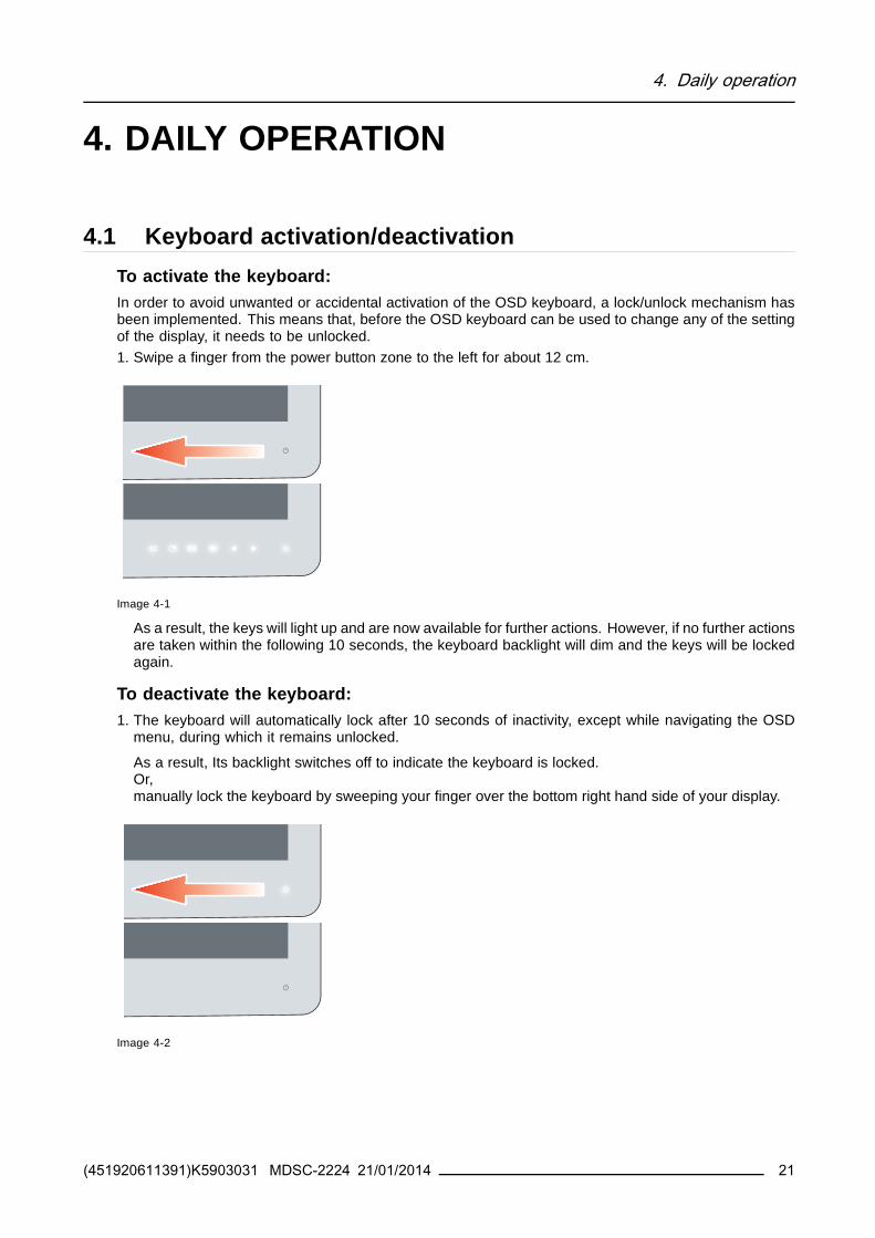
4 Daily operation
bull Main source selectionbull Multi-image configuration
bull Zoom factor selection
bull Brightness adjustment
Unlike the extended keyboard functions (described in next chapter) the shortkey func-tionality is immediately available without the need to first enable this in the OSD menu
When the extended keyboard functionality is enabled all the shortkey functions de-scribed below (except for the brightness adjustment) will no longer be available andwill be replaced by the corresponding extended keyboard functions described in thenext chapter
Overview of shortkeys
1 2 3 4 5
Image 4-5
1 Main source selection
2 Multi-image configuration
3 Zoom factor selection
4 Brightness decrease
5 Brightness increase
471 Main source selection
To quickly select the main source1 Use the Input selection key ( ) to scroll through all the possible input signals to select the main input
source
Available main source options dependent on display model
When the extended keyboard functionality is enabled this shortkey functions will nolonger be available and will be replaced by the corresponding extended keyboard func-tions described in the next chapter
472 Multi-image configuration
To quickly select the multi-image configuration1 Use the PiP selection key ( ) to scroll through all possible configurations of Picture-in-Picture (PiP) and
Side-by-Side (SbS)The different PiPSbS options are- Small PiP 30 of Primary height in top-right corner- Large PiP 50 of Primary height in top-right corner- Side-by-Side Primary and Secondary input of equal height
(451920611391)K5903031 MDSC-2224 21012014 25
4 Daily operation
Only a subset of multi-image configuration settings is available via this shortkey func-tion More multi-image configuration settings can be selected in the OSD menus
When the extended keyboard functionality is enabled this shortkey functions will nolonger be available and will be replaced by the corresponding extended keyboard func-tions described in the next chapter
473 Zoom factor selection
To quickly select the zoom factor1 Use the Image zoom key ( ) to select one of the available zoom factors
When the extended keyboard functionality is enabled this shortkey functions will nolonger be available and will be replaced by the corresponding extended keyboard func-tions described in the next chapter
474 Brightness adjustment
To quickly adjust the brightness1 While no OSD Menu is on the screen press the Brightness decrease ( ) or Brightness increase ( )
keys to adjust the brightness as desired
Brightness
50
Image 4-6
When the extended keyboard functionality is enabled this shortkey functions will re-main available
48 Extended keyboard functions
About extended keyboard functionsThe concept of the extended keyboard is to present a large selection of functions immediately availableto the user without the need to navigate through the OSD Menu
Once enabled through dedicated OSD menu function by simply pressing one of the first 3 keys on the leftthe user is presented with a list of new selections displayed on screen the new choices can be selectedby using each of the key just below the OSD text
If two options are available for one key the first key press will select the upper option a second pressselects the lower option
The different available extended keyboard functions are
26 (451920611391)K5903031 MDSC-2224 21012014
4 Daily operation
bull Main source selectionbull Second source selection
bull Multi-image configuration
bull Color temperature selectionbull Image size selection
bull Zoom factor selection
Unlike the shortkey functions (described before) the extended keyboard functionalitymust be first enabled in the OSD menu before you can make use of it Please refer to thededicated section in this manual for more details on how to enabledisable the extendedkeyboard functions
When the extended keyboard functionality is enabled all the shortkey functions de-scribed in previous chapter (except for the brightness adjustment) will no longer beavailable and will be replaced by the corresponding extended keyboard functions de-scribed below
Overview of extended keyboard
1 2 3
Image 4-7
Main source selection1
Second source selection
2 Multi-image configuration
Color temperature selection
Image size selection3
Zoom factor selection
481 Main source selection
To quickly select the main source1 While no OSD Menu is on the screen press the Input selection key ( ) to bring up the main source
quick selection menu
2 Toggle the available main source options by pressing the key corresponding to the desired optionIf two options are available for one key the first key press will select the upper option a second pressselects the lower optionThe current selection is marked in red
3 Press the stand-by key ( ) to confirm your choice and exit the main source quick selection menu
(451920611391)K5903031 MDSC-2224 21012014 27
4 Daily operation
Main source
VGA
DP
R G B
Y Pb Pr
S-Video
CVBS
DVI
SDI Nexxis 2nd Source
EXIT
Image 4-8
Note Available main source options dependent on display model
482 Second source selection
To quickly select the second source1 While no OSD Menu is on the screen press the Input selection key ( ) to bring up the main source
quick selection menu
2 Press the key to switch to the 2nd source quick selection menu
3 Toggle the available second source options by pressing the key corresponding to the desired optionIf two options are available for one key the first key press will select the upper option a second pressselects the lower optionThe current selection is marked in red
4 Press the stand-by key ( ) to confirm your choice and exit the second source quick selection menu
2nd Source
VGA
DP
R G B
Y Pb Pr
S-Video
CVBS
DVI
SDI Nexxis Main source
EXIT
Image 4-9
Note Available second source options dependent on display model
483 Multi-image configuration
To quickly select the multi-image configuration1 While no OSD Menu is on the screen press the PiP selection key ( ) to bring up the multi-image
configuration quick selection menu
2 Toggle the available multi-image configurations by pressing the key corresponding to the desired optionThe current selection is marked in red
3 Press the stand-by key ( ) to confirm your choice and exit the multi-image configuration quick selectionmenu
28 (451920611391)K5903031 MDSC-2224 21012014
4 Daily operation
Multi image config
Native Aspect Fill Small Large None
EXIT
Image 4-10
484 Common Functions Transfer function selection
To quickly select the transfer function1 While no OSD Menu is on the screen press the Image zoom key ( ) to bring up the common functions
quick selection menu
2 Toggle the available transfer function settings by pressing the key corresponding to the desired optionThe current selection is marked in red
3 Press the stand-by key ( ) to confirm your choice and exit the common functions quick selection menu
Common Functions
ITU 709 6500degK X-Ray Native Aspect Zoom
10
EXIT
Image 4-11
Note Only a subset of transfer function settings is available via this quick selection menu More transferfunction settings can be selected in the OSD menus
485 Common Functions Image size selection
To quickly select the image size1 While no OSD Menu is on the screen press the Image zoom key ( ) to bring up the common functions
quick selection menu
2 Toggle the available image size settings by pressing the key corresponding to the desired optionThe current selection is marked in red
3 Press the stand-by key ( ) to confirm your choice and exit the common functions quick selection menu
Common Functions
ITU 709 6500degK X-Ray Native Aspect Zoom
10
EXIT
Image 4-12
Note Only a subset of image size settings is available via this quick selection menu More image sizesettings can be selected in the OSD menus
(451920611391)K5903031 MDSC-2224 21012014 29
4 Daily operation
486 Common Functions Zoom factor selection
To quickly select the zoom factor1 While no OSD Menu is on the screen press the Image zoom key ( ) to bring up the common functions
quick selection menu
2 Toggle the available zoom factors by repeatedly pressing the key until the desired zoom factor isshown
3 Press the stand-by key ( ) to confirm your choice and exit the common functions quick selection menu
Common Functions
ITU 709 6500degK X-Ray Native Aspect Zoom
10
EXIT
Image 4-13
49 Menu lockingunlocking
To lockunlock the menuThe keyboard can be locked from the Menu to avoid unwanted access to OSD functions When the key-board is LOCKED only the OSD Menu key ( ) and the Stand-by key ( ) are active When the Menu OSDkey is pressed the Menu Locked window appears
1 To unlock the keyboard the following sequence of keys need to be pressed
Each time a key is pressed an asterisk is shown in the square boxes
After pressing the fourth key if the sequence is correct the main OSD menu is activated To unlock thekeyboard permanently the specific OSD function is required
Keyboard lockSequence 5 - 6 - 6 - 3
Image 4-14
30 (451920611391)K5903031 MDSC-2224 21012014
5 Advanced operation
5 ADVANCED OPERATION
51 OSD picture menu
Overview
bull Profile
bull Brightnessbull Contrast
bull Saturationbull Color temperature
bull Gamma
bull Sharpness
511 Profile
About profilesTo select a profile means to load a set of predefined video parameters like Brightness Contrast Satura-tion Input selection (Primary amp Secondary) Multi-image layout selection etc
The user can modify the default video parameters associated to each profile and save the new parameterssetting under the User 1 User 2 or User 3 profile The Factory and X Ray profiles can be temporarymodified but the factory default canrsquot be overwritten and can always be recalled through the recall profilemenu item
The available profiles for your display are
bull Factory
bull X Ray
bull User 1bull User 2
bull User 3
To select a profile1 Bring up the OSD main menu
2 Navigate to the Picture menu
3 Enter the Profile submenu
4 Select one of the available profiles and confirm
512 Brightness
To adjust the brightness level1 Bring up the OSD main menu
2 Navigate to the Picture menu
3 Enter the Brightness submenuThe command bar Brightness is highlighted
4 Set the brightness level as desired and confirm
(451920611391)K5903031 MDSC-2224 21012014 31
5 Advanced operation
The selected brightness is maintained at a constant level by the automatic backlightstabilization function
The brightness level can also be adjusted through a shortkey function
Brightness level is adjusted by controlling the backlight illumination only
513 Contrast
To adjust the contrast level1 Bring up the OSD main menu
2 Navigate to the Picture menu
3 Enter the Contrast submenuThe command bar Contrast is highlighted
4 Set the contrast level as desired and confirm
514 Saturation
To adjust the saturation level1 Bring up the OSD main menu
2 Navigate to the Picture menu
3 Enter the Saturation submenuThe command bar Saturation is highlighted
4 Set the saturation level as desired and confirm
515 Color temperature
About color temperature presetsThe available color temperature presets for your display are
bull 5600Kbull 6500K
bull 7600Kbull 9300K
bull ITU 709
bull Nativebull User
32 (451920611391)K5903031 MDSC-2224 21012014
5 Advanced operation
Factory calibration ndash White point
The White Color points associated with the Color Temperature 5600K 6500K 7600K or9300K are factory calibrated with a consequent reduction of the maximum luminancecompared to Native Color Temperature
Factory calibration ndash Color space
When ITU 709 is selected the White Color point and the RGB color primaries are ad-justed according to the target HDTV sRGB color space defined in the ITU-709 recom-mendation RGB primary calibration is performed within the physical limitation of theLCD panel used
Only in case the User preset has been selected it is possible to get access to the colorregulation commands described hereafter
To select a color temperature preset1 Bring up the OSD main menu
2 Navigate to the Picture menu
3 Enter the Color Temperature submenu
4 Select one of the available color temperature presets and confirmNote If you selected the User color temperature preset a new menu will be displayed allowing you to
manually adjust the gain and offset of red green and blue
516 Gamma
About gamma presetsThe available gamma presets for your display are
bull 18
bull 20
bull 22bull 24
bull Native (no correction curve is applied)bull X-ray (grayscale levels are following closely the DICOM curve)
To select a gamma preset1 Bring up the OSD main menu
2 Navigate to the Picture menu
3 Enter the Gamma submenu
4 Select one of the available gamma presets and confirm
517 Sharpness
To adjust the sharpness level1 Bring up the OSD main menu
2 Navigate to the Picture menu
(451920611391)K5903031 MDSC-2224 21012014 33
5 Advanced operation
3 Enter the Sharpness submenuThe command bar Sharpness is highlighted
4 Set the sharpness level as desired and confirm
52 Picture Advanced menuOverview
bull Black Levelbull Smart Video
bull Image Positionbull Auto Adjustment
bull Phase
bull ClockLine
521 Black Level
About black levelThis command allows to add or subtract an offset to the input video signal (available only on video formats)
To adjust the black level1 Bring up the OSD main menu
2 Navigate to the Picture advanced menu
3 Enter the Black Level submenuThe command bar Black Level is highlighted
4 Set the black level as desired and confirm
522 Smart Video
About Smart VideoThis function allows to reduce the video latency in the monitor if its frame rate is in the range of 50 - 60Hz To achieve a minimum latency select one of the surgical modes
The available Smart Video presets for your display are
bull Diagnostic (best picture quality)bull Surgical (low latency)
bull Surgical 1 (low latency optimized for fast moving images)
To select a Smart Video preset1 Bring up the OSD main menu
2 Navigate to the Picture advanced menu
3 Enter the Smart Video submenu
4 Select one of the available Smart Video presets and confirm
34 (451920611391)K5903031 MDSC-2224 21012014
5 Advanced operation
523 Image Position
This menu item is only available when VGA input is connected
To adjust the image position1 Bring up the OSD main menu
2 Navigate to the Picture advanced menu
3 Enter the Image Position submenuA small OSD menu will be activated indicating the horizontal and vertical image position offset
4 Use the and keys to move the picture up and down
5 Use the and keys to move the picture left and right
6 When finished use the key to exit from the small OSD menu
524 Auto Adjustment
This menu item is only available when VGA input is connected
About auto adjustmentWhen auto adjustment is activated the phase and clock per line parameters are automatically adjusted
To activate auto adjustment1 Bring up the OSD main menu
2 Navigate to the Picture advanced menu
3 Enter the Auto Adjustment submenuThe automatic picture adjustment is activated the phase and clock per line parameters are automati-cally adjusted
525 Phase
This menu item is only available when VGA input is connected
About phaseIf the result of the Auto Adjustment procedure described above isnrsquot satisfactory the Phase can be man-ually adjusted by following this procedure
To manually adjust the phase1 Bring up the OSD main menu
2 Navigate to the Picture advanced menu
3 Enter the Phase submenuThe command bar Phase is highlighted
4 Set the phase as desired and confirm
(451920611391)K5903031 MDSC-2224 21012014 35
5 Advanced operation
526 ClockLine
This menu item is only available when VGA input is connected
About clocklineIf the result of the Auto Adjustment procedure described above isnrsquot satisfactory the ClockLine can bemanually adjusted by following this procedure
To manually adjust the phase1 Bring up the OSD main menu
2 Navigate to the Picture advanced menu
3 Enter the ClockLine submenuThe command bar ClockLine is highlighted
4 Set the clockline as desired and confirm
53 Display Format menu
Overview
bull Main Source (Primary Source)bull Component Mode
bull Zoom
bull Image Sizebull 2nd Picture Mode
bull 2nd Picture Sourcebull 2nd Picture Position
bull Picture Swap
531 Main Source (Primary Source)
About main sourcesThe available main sources for your display are
bull Auto Search
bull Compositebull S-Video
bull Componentbull PC Analog
bull DVI 1bull DVI 2
bull SDI 1
bull SDI 2bull Nexxis
bull DisplayPort
36 (451920611391)K5903031 MDSC-2224 21012014
5 Advanced operation
Available main sources dependent on display model
The main source can also be selected through a shortkey function or via the extendedkeyboard functionality
To select the main source1 Bring up the OSD main menu
2 Navigate to the Display Format menu
3 Enter the Main Source submenu
4 Select one of the available main source and confirmNote If you selected the Auto Search preset the display will automatically detect the connected signal
532 Component Mode
About component modesThe available component modes for your display are
bull YPbPr
bull RGB
To select the component mode1 Bring up the OSD main menu
2 Navigate to the Display Format menu
3 Enter the Component Mode submenu
4 Select one of the available component modes and confirm
533 Zoom
About zoomThe available zoom factors for your display are
bull None
bull 10bull 20
bull 30bull 40
bull 50
The zoom factor can also be selected through a shortkey function or via the extendedkeyboard functionality
To select a zoom factor1 Bring up the OSD main menu
2 Navigate to the Display Format menu
(451920611391)K5903031 MDSC-2224 21012014 37
5 Advanced operation
3 Enter the Zoom submenu
4 Select one of the available zoom factors and confirm
534 Image Size
About image sizeThe available image sizes for your display are
bull Full Screen (fill the screen image aspect-ratio can be altered)
bull Aspect (fill the screen on largest dimension no modification in image aspect-ratio)bull Native (input pixel to LCD pixel mapping no scaling)
In Aspect and Native the image may be displayed with black bars on topbottom orleftright
The image size can also be selected via the extended keyboard functionality
To select the image size1 Bring up the OSD main menu
2 Navigate to the Display Format menu
3 Enter the Image Size submenu
4 Select one of the available image sizes and confirm
535 2nd Picture Mode
About 2nd picture modesThe available 2nd picture modes for your display are
bull Off
bull Small PiP 30 of Primary height in top-right cornerbull Large PiP 50 of Primary height in top-right corner
bull Side-by-Side Primary and Secondary input of equal height
bull SbS Native The 2 images are displayed with input pixel to LCD pixel mapping with image crop ifnecessary
bull SbS Fill Both images scaled to fill half of the screen with image crop if necessary
The 2nd picture mode (multi-image configuration) can also be selected via the extendedkeyboard functionality
To select the 2nd picture mode1 Bring up the OSD main menu
2 Navigate to the Display Format menu
3 Enter the 2nd Picture Mode submenu
4 Select one of the available 2nd picture modes and confirm
38 (451920611391)K5903031 MDSC-2224 21012014
5 Advanced operation
Multi image in Full HD available with any combination of input sources
Multi image in SD video available with any combination of input source except Compos-ite amp S-video
536 2nd Picture Source
About 2nd picture sourcesThe available 2nd picture sources for your display are
bull Auto Searchbull Composite
bull S-Videobull Component
bull PC Analog
bull DVI 1bull DVI 2
bull SDI 1bull SDI 2
bull Nexxisbull DisplayPort
The 2nd picture source can also be selected via the extended keyboard functionality
Independent Transfer Function
Gamma and Color temperature for the 2nd Picture Souce are always set to Native and6500K independently from the Transfer Function applied to the Main Picture SourceFor a perfect visualization of a X-ray image please select the X-ray input signal as Mainpicture and if needed the Video image as 2nd picture
To select the 2nd picture source1 Bring up the OSD main menu
2 Navigate to the Display Format menu
3 Enter the 2nd Picture Source submenu
4 Select one of the available 2nd picture sources and confirm
537 2nd Picture Position
About 2nd picture positionsThe available 2nd picture positions for your display are
bull Top Rightbull Top Left
bull Bottom Rightbull Bottom Left
(451920611391)K5903031 MDSC-2224 21012014 39
5 Advanced operation
To select the 2nd picture position1 Bring up the OSD main menu
2 Navigate to the Display Format menu
3 Enter the 2nd Picture Position submenu
4 Select one of the available 2nd picture positions and confirm
538 Picture Swap
About picture swappingTo swap pictures means to exchange (swap) main and 2nd picture
To swap pictures1 Bring up the OSD main menu
2 Navigate to the Display Format menu
3 Enter the Picture Swap submenu
4 Select the desired setting and confirm
54 Configuration menu
Overview
bull Information
bull Language
bull Failover modebull Extended keyboard
bull OSD settingbull Recall Profile
bull Save Profile
541 Information
About informationThe available information items for your display are
bull Model (commercial type identification)bull Operating Hours (backlight operation hours)
bull Firmware Release (firmware identification)
bull Hardware Version (main board identification)bull Option SDI (SDI module identification)
bull Serial Number ANxxxxxxxxxxxx
To access information1 Bring up the OSD main menu
2 Navigate to the Configuration menu
3 Enter the Information submenuThe different information items are shown
40 (451920611391)K5903031 MDSC-2224 21012014
5 Advanced operation
542 Language
About languagesThe available languages for your display are
bull English
bull Franccedilaisbull Deutsch
bull Espantildeol
bull Italiano
To select the language1 Bring up the OSD main menu
2 Navigate to the Configuration menu
3 Enter the Language submenu
4 Select one of the available languages and confirm
543 Failover mode
About failover modeThis function allows the automatic switch to a defined Backup source when the Main input signal is miss-ing
The display will automatically restore the Main input as soon as the signal is back
The Backup source is the input selected as ldquo2nd Picture Sourcerdquo with ldquo2nd Picture Moderdquo = ldquoOffrdquo
This Main amp Backup combination is stored at the moment the function ldquoFailover moderdquo is set to ldquoEnabledrdquo
Failover Mode is not selectable when either the Main Source or the 2nd Picture Source is set to ldquoAu-tosearchrdquo
Failover mode is automatically disabled when either the Main Source or the 2nd PictureSource is changed A warning message ldquoFailover offrdquo appears on the screen for a fewseconds
Returning to the original Main amp Backup combination will automatically re-enable theFailover feature
For the MNA version only Failover mode will be activated 7 seconds after the Nexxissignal becomes unavailable (delay required to allow a Nexxis layout change)
To enabledisable failover mode1 Bring up the OSD main menu
2 Navigate to the Configuration menu
3 Enter the Failover mode submenu
4 EnableDisable failover mode as desired and confirm
(451920611391)K5903031 MDSC-2224 21012014 41
5 Advanced operation
544 Extended keyboard
About the extended keyboardThe concept of the extended keyboard is to present a large selection of functions immediately availableto the user without the need to navigate through the OSD Menu
Once enabled by simply pressing one of the first 3 keys on the left the user is presented with a list of newselections displayed on screen the new choices can be selected by using each of the key just below theOSD text
If two options are available for one key the first key press will select the upper option a second pressselects the lower option
The different available extended keyboard functions are
bull Main source selection
bull Second source selection
bull Multi-image configurationbull Color temperature selection
bull Image size selectionbull Zoom factor selection
To enabledisable the extended keyboard1 Bring up the OSD main menu
2 Navigate to the Configuration menu
3 Enter the Extended keyboard submenu
4 EnableDisable the extended keyboard as desired and confirm
545 OSD setting
5451 OSD Horizontal Position
To adjust the OSD horizontal position1 Bring up the OSD main menu
2 Navigate to the Configuration menu
3 Enter the OSD setting submenu
4 Select OSD Hor PosThe command bar OSD Hor Pos is highlighted
5 Set the OSD horizontal position as desired and confirm
5452 OSD Vertical Position
To adjust the OSD vertical position1 Bring up the OSD main menu
2 Navigate to the Configuration menu
3 Enter the OSD setting submenu
4 Select OSD Ver PosThe command bar OSD Ver Pos is highlighted
5 Set the OSD vertical position as desired and confirm
42 (451920611391)K5903031 MDSC-2224 21012014
5 Advanced operation
5453 OSD Time-out
About OSD time-outThe available OSD time-out values for your display are
bull 10 Sec
bull 20 Secbull 30 Sec
bull 60 Sec
bull Disabled (=5 minutes)
To adjust the OSD time-out1 Bring up the OSD main menu
2 Navigate to the Configuration menu
3 Enter the OSD setting submenu
4 Select OSD Time-out
5 Select one of the available OSD time-out values and confirm
546 Recall Profile
About recalling profilesTo recall a profile means to restore the default factory settings (Factory and X Ray profiles) or recall theuse defined profiles
The available profiles to recall from your display are
bull Factory
bull X Raybull User 1
bull User 2bull User 3
To recall a profile1 Bring up the OSD main menu
2 Navigate to the Configuration menu
3 Enter the Recall Profile submenu
4 Select one of the available profiles to recall and confirm
547 Save Profile
About saving profilesThe user can modify the default video parameters associated to each profile and save the new parameterssetting under the User 1 User 2 or User 3 profile The Factory and X Ray profiles can be modified butthe factory default canrsquot be overwritten and can always be recalled through the recall profile menu item
The available profiles to save in your display are
bull User 1bull User 2
bull User 3
(451920611391)K5903031 MDSC-2224 21012014 43
5 Advanced operation
To save a profile1 Bring up the OSD main menu
2 Navigate to the Configuration menu
3 Enter the Save Profile submenu
4 Select one of the available profiles to save and confirm
55 System menu
Overview
bull Power on DVI 1
bull Power on DVI 2bull DVI Output
bull Keyboard lock
bull Keyboard backlightbull Power Saving
551 Power on DVI 1
About power on DVI 1This setting allows you to select the pin of DVI port 1 connector on which the +5V DC supply is applied
The available options are
bull Disabled
bull +5V on Pin 14
bull +5V on Pin 16
To select the power on DVI 11 Bring up the OSD main menu
2 Navigate to the System menu
3 Enter the Power on DVI 1 submenu
4 Select one of the available options and confirm
552 Power on DVI 2
About power on DVI 2This setting allows you to select the pin of DVI port 2 connector on which the +5V DC supply is applied
The available options are
bull Disabled
bull +5V on Pin 14bull +5V on Pin 16
To select the power on DVI 21 Bring up the OSD main menu
2 Navigate to the System menu
3 Enter the Power on DVI 2 submenu
44 (451920611391)K5903031 MDSC-2224 21012014
5 Advanced operation
4 Select one of the available options and confirm
553 DVI Output
About DVI outputThis setting allows you to select which digital input to replicate on DVI out
The available options are (depending on display version)
bull DVI 1
bull DVI 2bull Nexxis
bull None
This feature is subject to restrictions in case of Multi-image (PiP SbS)
To select the DVI output1 Bring up the OSD main menu
2 Navigate to the System menu
3 Enter the DVI output submenu
4 Select one of the available options and confirm
554 Keyboard lock
About keyboard lockingThis setting allows you to disable the keyboard functionality and avoid unwanted access to the OSD func-tions
Accessing the OSD menu is only possible after pressing a sequence of keys Please refer to the dedicatedsection for more details (Keyboard lockingunlocking)
To enabledisable keyboard locking1 Bring up the OSD main menu
2 Navigate to the System menu
3 Enter the Keyboard Lock submenu
4 EnableDisable keyboard locking as desired and confirm
555 Keyboard backlight
About the keyboard backlightBy default after lighting up the keyboard backlight will dim again if no further actions are taken within thefollowing 5 seconds However this behavior can be changed so that the keyboard backlight is always on
To adjust the keyboard backlight1 Bring up the OSD main menu
2 Navigate to the System menu
3 Enter the Keyboard Backlight submenu
4 Select one of the available options and confirm
(451920611391)K5903031 MDSC-2224 21012014 45
5 Advanced operation
556 Power Saving
About power savingWhen the active input(s) is (are) missing this setting allows the display to switch off the backlight andenter a low power mode In this status the availability of the selected input is checked periodically
When the unit is in power save mode the unit can exit this power save mode in twocases
1 When a signal is applied on the selected input (or any input in case of auto)
2 By activating the OSD menu see OSD menu activation page 23
To enabledisable power saving1 Bring up the OSD main menu
2 Navigate to the System menu
3 Enter the Power Saving submenu
4 EnableDisable power saving as desired and confirm
46 (451920611391)K5903031 MDSC-2224 21012014
6 Important information
6 IMPORTANT INFORMATION
61 Safety information
General recommendationsRead the safety and operating instructions before operating the device
Retain safety and operating instructions for future reference
Adhere to all warnings on the device and in the operating instructions manual
Follow all instructions for operation and use
Electrical Shock or Fire HazardTo prevent electric shock or fire hazard do not remove cover
No serviceable parts inside Refer servicing to qualified personnel
Do not expose this apparatus to rain or moisture
Type of protection (Electrical)Equipment with external power supply Class I equipment
Degree of safety (flammable anesthetic mixture)Equipment not suitable for use in the presence of a flammable anesthetic mixture with air or with oxygenor nitrous oxide
Non-patient care equipment
bull Equipment primarily for use in a health care facility that is intended for use where contact with a patientis unlikely (no applied part)
bull The equipment may not be used with life support equipmentbull The user is not supposed to touch SIPSOPs and the patient at the same time
Mission critical applicationsWe strongly recommend there is a replacement display immediately available in mission critical applica-tions
Use of Electrical Surgical KnivesProvide as much distance as possible between the electrosurgical generator and other electronic equip-ment (such as monitors) An activated electrosurgical generator may cause interference with them Theinterference can activate the OSD menu of the display and as such disrupt the functionality of the display
Power connection ndash Equipment with external 24 VDC power supply
bull Power requirements The equipment must be powered using the delivered medical approved 24 VDC( ) SELV power supply
bull The medical approved DC ( ) power supply must be powered by the AC mains voltage
bull The power supply is specified as a part of the ME equipment or combination is specified as a MEsystem
bull To avoid the risk of electric shock this equipment must only be connected to a supply mains withprotective earth
bull The equipment should be installed near an easily accessible outlet
bull The equipment is intended for continuous operation
(451920611391)K5903031 MDSC-2224 21012014 47
6 Important information
bull The compliance of this monitor with Medical Safety and EMC requirements has been evaluated usingthe external (optional) Skynet medical power supply model BAR-A159 If a different power supply willbe used further investigation for Safety and EMC requirements have to be performed at system level
Power cords
bull Utilize a UL-listed detachable power cord 3-wire type SJ or equivalent 18 AWG min rated 250 Vmin provided with a hospital-grade type plug 5-15P configuration for 120V application or 6-15P for240V application
bull Do not overload wall outlets and extension cords as this may result in fire or electric shock
bull Mains lead protection (US Power cord) Power cords should be routed so that they are not likely tobe walked upon or pinched by items placed upon or against them paying particular attention to cordsat plugs and receptacles
bull The power supply cord should be replaced by the designated operator only at all timebull Use a power cord that matches the voltage of the power outlet which has been approved and complies
with the safety standard of your particular country
Transient over-voltageIf the device is not used for a long time disconnect it from the AC inlet to avoid damage by transientover-voltage
To fully disengage the power to the device please disconnect the power cord from the AC inlet
ConnectionsAny external connection with other peripherals must follow the requirements of clause 16 of IEC60601-13rd ed or Table BBB201 of IEC 60601-1-1 for the medical electrical systems
Water and moistureThe equipment is IP21 compliant (IPx5 front side only)
The power supply is not approved for IP21 The power supply must be mounted in a flatposition for best resistance to fluids
VentilationDo not cover or block any ventilation openings in the cover of the set When installing the device in acupboard or another closed location heed the necessary space between the set and the sides of thecupboard
Installation
bull Place the equipment on a flat solid and stable surface that can support the weight of at least 3 equip-ments If you use an unstable cart or stand the equipment may fall causing serious injury to a childor adult and serious damage to the equipment
bull Do not allow to climb or rest on the equipment
bull When adjusting the angle of the equipment move it slowly so as to prevent the equipment from movingor slipping off from its stand or arm
bull When the equipment is attached to an arm do not use the equipment as a handle or grip in order tomove the equipment Please refer to the instruction manual of the arm for instructions on how to movethe arm with the equipment
bull Provide full attention to safety during installation periodic maintenance and examination of this equip-ment
48 (451920611391)K5903031 MDSC-2224 21012014
6 Important information
bull Sufficient expertise is required for installing this equipment especially to determine the strength of thewall for withstanding the displayrsquos weight Be sure to entrust the attachment of this equipment to thewall to licensed contractors of Barco and pay adequate attention to safety during the installation andusage
bull Barco is not liable for any damage or injury caused by mishandling or improper installation
General warnings
bull All devices and complete setup must be tested and validated before taking into operation
bull The installer needs to foresee a backup system in case the video falls away
Technical data
bull The monitor is intended for indoor usebull The monitor has been designed to be used in landscape position with a tilt of -10deg (backward) and
+10deg (forward)
bull Power consumption 24VDC 32A maxbull Operating Temperature 10-35degC for performance 0-40degC for safety
bull Operating Humidity 10-90 RH
bull Operating Altitude 3000m maxbull Storage -20 divide +60degC 10 divide 90RH
bull IP Protection IP21 (IPx5 front side only) in vertical positionbull Class I Equipment according to the type of protection against electric shock
bull The monitor is not intended to be sterilized
bull The monitor has not applied parts but the front side of the LCD panel and the plastic enclosure havebeen treated as applied part because considered accidentally touchable by the patient for a time lt1minute
This apparatus conforms toMedical Equipment
3rd edition
ANSIAAMI ES 60601-1 3rd edition 2005 EN 60601 3rd edition 2006 IEC 60601-1 3rd edition (2005)CE (MDD) Class I essential requirements of MDD 9342EEC version 2007 (in effect as of March 2010)CANCSA-C222 No 606011-08
EMC
IEC EN 60601-1-2 2007
EN 55011 CISPR11 (MDSC-2224-MNA Class A MDSC-2224-LED Class B)
National Scandinavian Deviations for CL 172Finland Laite on liitettaumlvauml suojamaadoituskoskettimilla varustettuun pistorasiaan
Norway Apparatet maring tilkoples jordet stikkontakt
Sweden Apparaten skall anslutas till jordat uttag
62 Environmental informationDisposal InformationWaste Electrical and Electronic Equipment
(451920611391)K5903031 MDSC-2224 21012014 49
6 Important information
This symbol on the product indicates that under the European Directive 201219EU governingwaste from electrical and electronic equipment this product must not be disposed of with other municipalwaste Please dispose of your waste equipment by handing it over to a designated collection point for therecycling of waste electrical and electronic equipment To prevent possible harm to the environment orhuman health from uncontrolled waste disposal please separate these items from other types of wasteand recycle them responsibly to promote the sustainable reuse of material resources
For more information about recycling of this product please contact your local city office or your municipalwaste disposal service
For details please visit the Barco website at httpwwwbarcocomenAboutBarcoweee
Turkey RoHS compliance
Tuumlrkiye Cumhuriyeti AEEE Youmlnetmeliğine Uygundur
[Republic of Turkey In conformity with the WEEE Regulation]
中国大陆 ROHS (Chinese Mainland RoHS)根据中国大陆《电子信息产品污染控制管理办法》(也称为中国大 陆RoHS) 以下部分列出了Barco 产品中可能包含的有毒和 或有 害物质的名称和含量中国大陆RoHS 指令包含在中国信息产业部 MCV 标准ldquo 电子信息产品中有毒物质的限量要求 中
According to the China Administration on Control of Pollution Caused by Electronic Information Products(Also called RoHS of Chinese Mainland) the table below lists the names and contents of toxic andorhazardous substances that Barcorsquos product may contain The RoHS of Chinese Mainland is included inthe MCV standard of the Ministry of Information Industry of China in the section Limit Requirements oftoxic substances in Electronic Information Products
零件项目(名称)
Component name
有毒有害物质或元素
Hazardous substances and elements铅Pb
汞
Hg
镉Cd
六价铬Cr6+
多溴联苯
PBB
多溴二苯醚PBDE
印制电路配件
Printed Circuit Assemblies
X O O O O O
液晶面板
LCD panel
X O O O O O
外接电(线)缆External Cables
X O O O O O
內部线路Internal wiring
O O O O O O
金属外壳
Metal enclosure
O O O O O O
塑胶外壳
Plastic enclosure
O O O O O O
散热片(器)
Heatsinks
O O O O O O
风扇
Fan
O O O O O O
50 (451920611391)K5903031 MDSC-2224 21012014
6 Important information
零件项目(名称)
Component name
有毒有害物质或元素
Hazardous substances and elements铅Pb
汞
Hg
镉Cd
六价铬Cr6+
多溴联苯
PBB
多溴二苯醚PBDE
电源供应器
Power Supply Unit
X O O O O O
文件说明书Paper Manuals
O O O O O O
光盘说明书CD manual
O O O O O O
O 表示该有毒有害物质在该部件所有均质材料中的含量均在 SJT 11363-2006 标准规定的限量要求以下
O Indicates that this toxic or hazardous substance contained in all of the homogeneous materials forthis part is below the limit requirement in SJT11363-2006X 表示该有毒有害物质至少在该部件的某一均质材料中的含量超出 SJT 11363-2006 标准规定的限量要求
X Indicates that this toxic or hazardous substance contained in at least one of the homogeneousmaterials used for this part is above the limit requirement in SJT11363-2006
在中国大陆销售的相应电子信息产品(EIP)都必须遵照中国大陆《电子信息产品污染控制标识要求》标准贴上环保使用期限(EFUP)标签Barco产品所采用的EFUP标签(请参阅实例徽标内部的编号使用于制定产品)基于中国大陆的《电子信息产品环保使用期限通则》标准
All Electronic Information Products (EIP) that are sold within Chinese Mainland must comply with theldquoElectronic Information Products Pollution Control Labeling Standardrdquo of Chinese Mainland marked withthe Environmental Friendly Use Period (EFUP) logo The number inside the EFUP logo that Barco uses(please refer to the photo) is based on the ldquoStandard of Electronic Information Products EnvironmentalFriendly Use Periodrdquo of Chinese Mainland
Image 6-1
RoHSDirective 201165EC on the restriction of certain hazardous substances in electrical and electronic equip-ment
According to what declared by our components suppliers this product is RoHS compliant
63 Biological hazard and returns
OverviewThe structure and the specifications of this device as well as the materials used for manufacturing makesit easy to wipe and clean and therefore suitable to be used for various applications in hospitals and othermedical environments where procedures for frequent cleaning are specified
However normal use shall exclude biological contaminated environments to prevent spreading of infec-tions
Therefore use of this device in such environments is at the exclusive risk of Customer In case this deviceis used where potential biological contamination cannot be excluded
(451920611391)K5903031 MDSC-2224 21012014 51
6 Important information
Customer shall implement the decontamination process as defined in the latest edition of the ANSIAAMIST35 standard on each single failed Product that is returned for servicing repair reworking or failureinvestigation to Seller (or to the Authorized Service Provider) At least one adhesive yellow label shall beattached on the top site of the package of returned Product and accompanied by a declaration statementproving the Product has been successfully decontaminated
Returned Products that are not provided with such external decontamination label andor whenever suchdeclaration is missing can be rejected by Seller (or by the Authorized Service Provider) and shipped backat Customer expenses
64 Regulatory compliance information
Indications for useThis device is intended to be used in operation rooms to display images from endoscopic cameras roomand boom cameras ultrasound cardiology PACS anesthesiology and patient information It is not in-tended for diagnosis
FCC Class B (valid for MDSC-2224 LED version)This device complies with Part 15 of the FCC Rules Operation is subject to the following two conditions(1) this device may not cause harmful interference and (2) this device must accept any interference re-ceived including interference that may cause undesired operation
This equipment has been tested and found to comply with the limits for a Class B digital device pursuantto Part 15 of the FCC Rules These limits are designed to provide reasonable protection against harmfulinterference in a residential installation This equipment generates uses and can radiate radio frequencyenergy and if not installed and used in accordance with the instructions may cause harmful interferenceto radio communications However there is no guarantee that interference will not occur in a particularinstallation If this equipment does cause harmful interference to radio or television reception which canbe determined by turning the equipment off and on the user is encouraged to try to correct the interferenceby one or more of the following measures
bull Reorient or relocate the receiving antennabull Increase the separation between the equipment and receiver
bull Connect the equipment into an outlet on a circuit different from that to which the receiver is connectedbull Consult the dealer or an experienced radioTV technician for help
FCC Class A (valid for MDSC-2224 MNA version)This equipment has been tested and found to comply with the limits of a class A digital device pursuantto Part 15 of the FCC rules These limits are designed to provide reasonable protection against harmfulinterference when the equipment is operated in a commercial environment This equipment generatesuses and can radiate radio frequency energy and if not installed and used in accordance with the instruc-tion manual may cause harmful interference to radio communications Operation of this equipment in aresidential area is likely to cause harmful interference in which case the user will be required to correctthe interference at his own expense
Canadian noticeThis ISM device complies with Canadian ICES-001
Cet appareil ISM est conforme agrave la norme NMB-001 du Canada
52 (451920611391)K5903031 MDSC-2224 21012014
6 Important information
65 Cleaning and disinfection
Instructions
bull Be sure to unplug the power cord from the mains when cleaning your LCD monitor
bull Take care not to scratch the front surface with any hard or abrasive materialbull Dust finger marks grease etc can be removed with a soft damp cloth (a small amount of mild deter-
gent can be used on the damp cloth)
bull Wipe off water drop immediately
Possible cleaning solutions
bull 70 percent isopropyl alcoholbull 16 percent aqueous ammonia
bull Cidexreg (24 percent glutaraldehyde solution)
bull Sodium hypochlorite (bleach) 10 percentbull ldquoGreen soaprdquo (USP)
bull 05 percent Chiorhexidine in 70 percent isopropyl alcoholbull Like Cleansafereg optical cleaning liquid
66 Explanation of symbols
Symbols on the deviceOn the device or power supply you may find the following symbols (nonrestrictive list)
Indicates the device meets the requirements of the applicable EC directives
Indicates compliance with Part 15 of the FCC rules (Class A or Class B)
Indicates the device is approved according to the UL Recognition regulations
Indicates the device is approved according to the UL Demko regulations
Indicates the device is approved according to the CCC regulations
Indicates the device is approved according to the VCCI regulations
Indicates the device is approved according to the KC regulations
Indicates the device is approved according to the BSMI regulations
(451920611391)K5903031 MDSC-2224 21012014 53
6 Important information
Indicates the USB connectors on the device
Indicates the DisplayPort connectors on the device
Indicates the manufacturing date
Indicates the temperature limitations1 for the device to safely operate within specs
Indicates the device serial no
Warning dangerous voltage
Caution
Consult the operating instructions
Indicates this device must not be thrown in the trash but must be recycledaccording to the European WEEE (Waste Electrical and Electronic Equipment)directive
Indicates Direct Current (DC)
Indicates Alternating Current (AC)
Stand-by
67 Legal disclaimer
Disclaimer noticeAlthough every attempt has been made to achieve technical accuracy in this document we assume noresponsibility for errors that may be found Our goal is to provide you with the most accurate and usabledocumentation possible if you discover errors please let us know
Barco software products are the property of Barco They are distributed under copyright by Barco NV orBarco Inc for use only under the specific terms of a software license agreement between Barco NV orBarco Inc and the licensee No other use duplication or disclosure of a Barco software product in anyform is authorized
1 Values for xx and yy can be found in the technical specifications paragraph
54 (451920611391)K5903031 MDSC-2224 21012014
6 Important information
The specifications of Barco products are subject to change without notice
TrademarksAll trademarks and registered trademarks are property of their respective owners
Copyright noticeThis document is copyrighted All rights are reserved Neither this document nor any part of it maybe reproduced or copied in any form or by any means - graphical electronic or mechanical includingphotocopying taping or information storage and retrieval systems - without written permission of Barco
copy 2013 Barco NV All rights reserved
68 Technical specifications
OverviewScreen technology TFT AM LCD
Active screen size (diagonal) 611 mm (241)
Active screen size (H x V) 518 x 324 mm (204 x 127)
Aspect ratio (HV) 1610
Resolution W-UXGA (1920 x 1200)
Pixel pitch 0270 mm
Color imaging Yes
Color support 1073 million
Viewing angle (H V) 178deg
Maximum luminance 350 cdmsup2 (typical)
Contrast ratio 10001
Response time (average Grayto Gray)
6 ms (typ)
Housing color White
DVI-I Single Link (digital amp analog ndash HDMI video support with HDCP)
DisplayPort (VESA std 11a)
RGBS
VGA (only computer VESA signals accepted)
S-video
Composite video
Component video
SDIHD-SDI3GSDI
Video input signals
Nexxis fiber optic input
DVI
CVBS
S-video
Video output signals
SDI
Power source requirementsfor external power supply(nominal)
100-250V
LED version 24VDC 23AmaxPower source requirements fordisplay power input MNA version 24VDC 32Amax
(451920611391)K5903031 MDSC-2224 21012014 55
6 Important information
LED version 65WPower consumption
MNA version 85W
Power save mode Yes
Dot clock 165 MHz max (DVI)
OSD languages English French German Spanish Italian
Display dimensions wo stand(W x H x D)
5954 x 414 x 84 mm (2344 x 163 x 331 in)
Power Supply dimensions (Wx H x D)
210 x 103 x 52 mm (827 x 406 x 205 in)
Dimensions packaged (W x Hx D)
685 x 570 x 170 mm (2697 x 2244 x 669 in)
Net weight display wo stand 79 kg (174 lbs) (95 kg (209 lbs) incl power supply and accessories)
Net weight power supply 15 kg (331 lbs)
Net weight packaged wostand
120 kg (265 lbs)
Power supply DC output cablelength
25 m (82 ft)
Mounting standard VESA (100 mm)
Screen protection Protective non-reflective PMMA cover
Recommended modalities Endoscopy Laparoscopy PACS PM US CT MR
Certifications ANSIAAMI ES 60601-1 3rd edition 2005 EN 60601 3rd edition2006 IEC 60601-1 3rd edition (2005) CE (MDD) Class I essentialrequirements of MDD 9342EEC version 2007 (in effect as of March2010) CANCSA-C222 No 606011-08 IEC EN 60601-1-2 2007EN 55011 CISPR11 (MDSC-2224-MNA Class A MDSC-2224 LEDClass B) FCC (A or B depending on model) RoHs compliant IP21(IPx5 front side only)User Guide
Video cable (DVI Dual Link)
Mains cables (European (CEBECKEMA) USA (ULCSA))
Supplied accessories
External power supply
Optional accessories Barco stand (K9302032A)
Power extension cable 10m (K3495066)
Power extension cable 30m (K3495068)Warranty 3 years
Operating temperature 10-35degC for performance 0-40degC for safety
Storage temperature -20 divide +60degC
Operating humidity 10 divide 90 (non-condensing)
Storage humidity 10 divide 90 (non-condensing)
Operating altitude 3000 m max
Storage altitude 12000 m max
Timings DVI-VGAItem Name Pixel x Line Format Hor Fr
(kHz)Vert Fr(Hz)
HorTotal
VertTotal
DVI VGA
1 480i 720 x 487 NTSC 15734 5994 Y N
2 480p59 720 x 480 480p 3147 5994 Y N
3 480p60 720 x 480 480p 315 60 Y N
4 576i 720 x 576 PAL I 15625 50 Y N
5 576p 720 x 576 576p 3125 50 Y N
56 (451920611391)K5903031 MDSC-2224 21012014
6 Important information
Item Name Pixel x Line Format Hor Fr(kHz)
Vert Fr(Hz)
HorTotal
VertTotal
DVI VGA
6 720p29 1280 x 720 720p 2248 2997 Y N
7 720p30 1280 x 720 720p 225 30 Y N
8 720p50 1280 x 720 720p 375 50 Y N
9 720p59 1280 x 720 720p 4496 5994 Y N
10 720p60 1280 x 720 720p 45 60 Y N
11 1080i25 1920 x 1080 1080i 2813 50 Y N
12 1080i29 1920 x 1080 1080i 3372 5994 Y N
13 1080i30 1920 x 1080 1080i 3375 60 Y N
14 1080p29 1920 x 1080 1080p 3372 2997 Y N
15 1080p30 1920 x 1080 1080p 3375 30 Y N
16 1080p50 1920 x 1080 1080p 5625 50 Y N
17 1080p59 1920 x 1080 1080p 67433 5994 Y N
18 1080p60 1920 x 1080 1080p 675 60 Y N
19 DMT0660 604 x 480 VGA 315 60 Y Y
20 DMT0672 604 x 480 VGA 3786 72808 Y Y
21 DMT0675 604 x 480 VGA 375 75 Y Y
22 DMT0685 604 x 480 VGA 43269 85008 Y Y
23 DMT0856 800 x 600 SVGA 3516 5625 Y Y
24 DMT0860 800 x 600 SVGA 3788 6032 Y Y
25 DMT0872 800 x 600 SVGA 4808 7219 Y Y
26 DMT0875 800 x 600 SVGA 46875 75 Y Y
27 DMT0885 800 x 600 SVGA 5374 85061 Y Y
28 DMT1060 1027 x 768 XGA 484 60 Y Y
29 DMT1070 1024 x 768 XGA 564 70 Y(Diagmode)2
Y (Diagmode) 2
30 DMT1075 1024 x 768 XGA 60 75 Y Y
31 DMT1085 1024 x 768 XGA 687 85 Y Y
32 DMT1175 1152 x 864 XGA+ 675 75 Y Y
33 DMT1260G 1280 x 1024 SXGA 64 60 Y Y
34 DMT1275G 1280 x 1024 SXGA 79976 75025 Y Y
35 DMT1285G 1280 x 1024 SXGA 911 85 Y Y
36 DMT1660 1600 x 1200 UXGA 75 60 Y Y
37 CVR1460 1400 x 1050 SXGA+ 64744 59948 Y Y
38 CVT1460 1400 x 1050 SXGA+(VESA)
6532 5998 Y Y
39 CVR1660D 1680 x 1050 WSXGA+1 6467 5988 Y Y
40 CVT1660D 1680 x 1050 WSXGA+2 6529 5995 Y Y
41 CVT 1920 x 1200 WUXGA1 74038 5995 Y Y
42 IBM 640 x 350 315 70 800 449 Y(Diagmode)2
N
43 VESA 640 x 350 379 85 832 446 Y Y
44 VESA 640 x 400 248 563 848 440 N Y
2 OSD Smart Video set to ldquoDiagnosticrdquo
(451920611391)K5903031 MDSC-2224 21012014 57
6 Important information
Item Name Pixel x Line Format Hor Fr(kHz)
Vert Fr(Hz)
HorTotal
VertTotal
DVI VGA
45 IBM 640 x 400 315 700 800 449 Y(Diagmode)2
N
46 VESA 640 x 400 379 850 832 446 Y Y
Timings Comp - SOGItem Name Pixel x Line Format Hor Fr
(kHz)Vert Fr(Hz)
HorTotal
VertTotal
SOG RGBS YPbPr
1 480i 720 x 487 NTSC 15734 5994 Y Y
2 480p59 720 x 480 480p 3147 5994 Y Y
3 480p60 720 x 480 480p 315 60 Y Y
4 576i 720 x 576 PAL I 15625 50 Y Y
5 576p 720 x 576 576p 3125 50 Y Y
8 720p50 1280 x 720 720p 375 50 Y Y
9 720p59 1280 x 720 720p 4496 5994 Y Y
10 720p60 1280 x 720 720p 45 60 Y Y
11 1080i25 1920 x 1080 1080i 2813 50 Y Y
12 1080i29 1920 x 1080 1080i 3372 5994 Y Y
13 1080i30 1920 x 1080 1080i 3375 60 Y Y
14 1080p29 1920 x 1080 1080p 3372 2997 Y Y
15 1080p30 1920 x 1080 1080p 3375 30 Y Y
16 1080p50 1920 x 1080 1080p 5625 50 Y Y
17 1080p59 1920 x 1080 1080p 67433 5994 Y Y
18 1080p60 1920 x 1080 1080p 675 60 Y Y
Timings SDIItem Name Pixel x Line Format Hor Fr
(kHz)Vert Fr(Hz)
HorTotal
VertTotal
SDI(Ypb)
RGBS YPbPr
1 480i 720 x 487 NTSC 15734 5994 Y Y
4 576i 720 x 576 PAL I 15625 50 Y Y
8 720p50 1280 x 720 720p 375 50 Y Y
9 720p59 1280 x 720 720p 4496 5994 Y Y
10 720p60 1280 x 720 720p 45 60 Y Y
11 1080i25 1920 x 1080 1080i 2813 50 Y Y
12 1080i29 1920 x 1080 1080i 3372 5994 Y Y
13 1080i30 1920 x 1080 1080i 3375 60 Y Y
14 1080p29 1920 x 1080 1080p 3372 2997 Y Y
15 1080p30 1920 x 1080 1080p 3375 30 Y Y
16 1080p50 1920 x 1080 1080p 5625 50 Y Y
17 1080p59 1920 x 1080 1080p 67433 5994 Y Y
18 1080p60 1920 x 1080 1080p 675 60 Y Y
SDI Standard ComplianceSMPTE 425M (level A) SMPTE 424M SMPTE 292M SMPTE 296M ITU-R BT656 ITU-R BT601
58 (451920611391)K5903031 MDSC-2224 21012014
6 Important information
SDI Video SamplingY Cb Cr 422
Dimensions5954 mm (2344rdquo) 84 mm (331rdquo)
414
mm
(16
3rdquo)
100
mm
(3
94rdquo)
100 mm (394rdquo)
Image 6-2
69 Open source license information
Open source license informationOpen source license usage
(451920611391)K5903031 MDSC-2224 21012014 59
6 Important information
This product contains software components released under an Open Source license A copy of the sourcecode is available on request by contacting your Barco customer support representative
EACH SEPARATE OPEN SOURCE SOFTWARE COMPONENT AND ANY RELATED DOCUMENTA-TION ARE PROVIDED AS IS WITHOUT EXPRESS OR IMPLIED WARRANTY INCLUDING BUT NOTLIMITED TO THE IMPLIED WARRANTIES OF MERCHANTABILITY AND FITNESS FOR A PARTICU-LAR PURPOSE IN NO EVENT SHALL THE COPYRIGHTHOLDER OR ANY OTHER CONTRIBUTORBE LIABLE FOR DIRECT INCIDENTAL OR CONSEQUENTIAL DAMAGES EVEN IF ADVISED OF THEPOSSIBILITY OF SUCH DAMAGES MORE INFORMATIONDETAILS IS TO BE FOUND IN EACH SPE-CIFIC OPEN SOURCE LICENSE
Copyright on each Open Source Software component belongs to the respective initial copyright holdereach additional contributor andor their respective assignee(s) as may be identified in the respective doc-umentation source code README file or otherwise You shall not remove or obscure or otherwise alterthe respective copyrights
You acknowledge living up to the conditions of each separate Open Source Software license
A list of the Open Source Software components used is available in the applicable EULA through the(customer section of the) Barco website or through other (online) means
60 (451920611391)K5903031 MDSC-2224 21012014
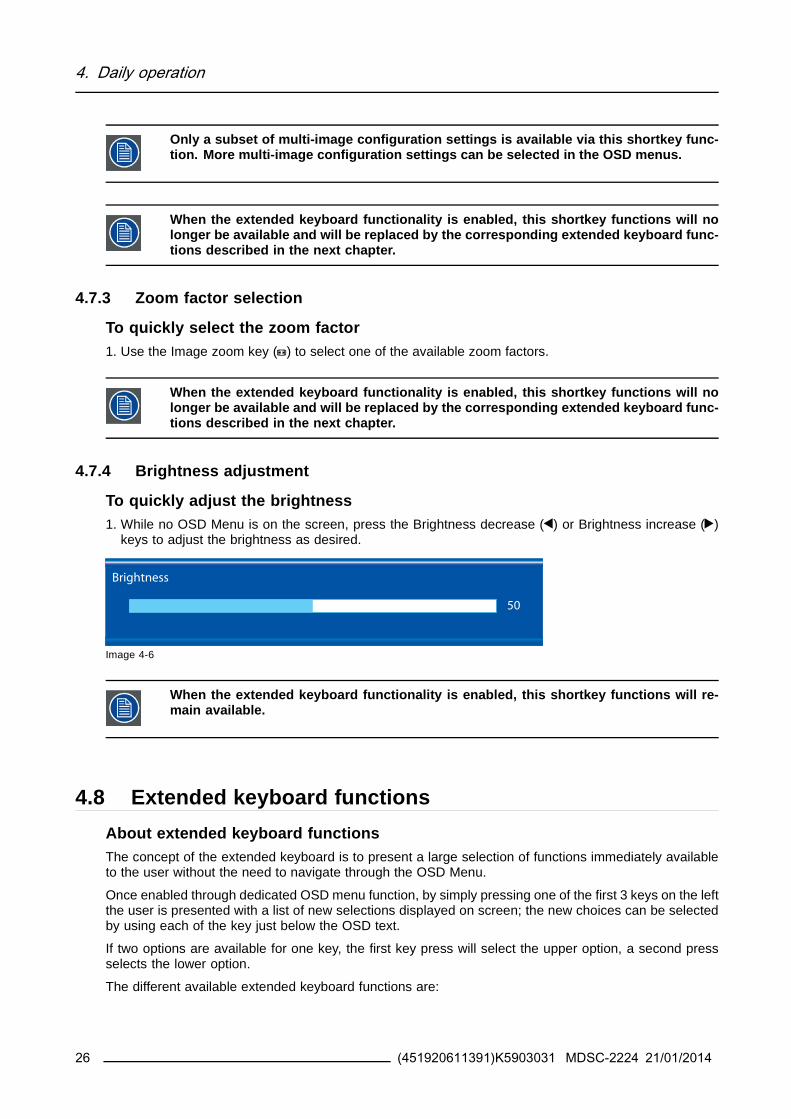
4 Daily operation
486 Common Functions Zoom factor selection
To quickly select the zoom factor1 While no OSD Menu is on the screen press the Image zoom key ( ) to bring up the common functions
quick selection menu
2 Toggle the available zoom factors by repeatedly pressing the key until the desired zoom factor isshown
3 Press the stand-by key ( ) to confirm your choice and exit the common functions quick selection menu
Common Functions
ITU 709 6500degK X-Ray Native Aspect Zoom
10
EXIT
Image 4-13
49 Menu lockingunlocking
To lockunlock the menuThe keyboard can be locked from the Menu to avoid unwanted access to OSD functions When the key-board is LOCKED only the OSD Menu key ( ) and the Stand-by key ( ) are active When the Menu OSDkey is pressed the Menu Locked window appears
1 To unlock the keyboard the following sequence of keys need to be pressed
Each time a key is pressed an asterisk is shown in the square boxes
After pressing the fourth key if the sequence is correct the main OSD menu is activated To unlock thekeyboard permanently the specific OSD function is required
Keyboard lockSequence 5 - 6 - 6 - 3
Image 4-14
30 (451920611391)K5903031 MDSC-2224 21012014
5 Advanced operation
5 ADVANCED OPERATION
51 OSD picture menu
Overview
bull Profile
bull Brightnessbull Contrast
bull Saturationbull Color temperature
bull Gamma
bull Sharpness
511 Profile
About profilesTo select a profile means to load a set of predefined video parameters like Brightness Contrast Satura-tion Input selection (Primary amp Secondary) Multi-image layout selection etc
The user can modify the default video parameters associated to each profile and save the new parameterssetting under the User 1 User 2 or User 3 profile The Factory and X Ray profiles can be temporarymodified but the factory default canrsquot be overwritten and can always be recalled through the recall profilemenu item
The available profiles for your display are
bull Factory
bull X Ray
bull User 1bull User 2
bull User 3
To select a profile1 Bring up the OSD main menu
2 Navigate to the Picture menu
3 Enter the Profile submenu
4 Select one of the available profiles and confirm
512 Brightness
To adjust the brightness level1 Bring up the OSD main menu
2 Navigate to the Picture menu
3 Enter the Brightness submenuThe command bar Brightness is highlighted
4 Set the brightness level as desired and confirm
(451920611391)K5903031 MDSC-2224 21012014 31
5 Advanced operation
The selected brightness is maintained at a constant level by the automatic backlightstabilization function
The brightness level can also be adjusted through a shortkey function
Brightness level is adjusted by controlling the backlight illumination only
513 Contrast
To adjust the contrast level1 Bring up the OSD main menu
2 Navigate to the Picture menu
3 Enter the Contrast submenuThe command bar Contrast is highlighted
4 Set the contrast level as desired and confirm
514 Saturation
To adjust the saturation level1 Bring up the OSD main menu
2 Navigate to the Picture menu
3 Enter the Saturation submenuThe command bar Saturation is highlighted
4 Set the saturation level as desired and confirm
515 Color temperature
About color temperature presetsThe available color temperature presets for your display are
bull 5600Kbull 6500K
bull 7600Kbull 9300K
bull ITU 709
bull Nativebull User
32 (451920611391)K5903031 MDSC-2224 21012014
5 Advanced operation
Factory calibration ndash White point
The White Color points associated with the Color Temperature 5600K 6500K 7600K or9300K are factory calibrated with a consequent reduction of the maximum luminancecompared to Native Color Temperature
Factory calibration ndash Color space
When ITU 709 is selected the White Color point and the RGB color primaries are ad-justed according to the target HDTV sRGB color space defined in the ITU-709 recom-mendation RGB primary calibration is performed within the physical limitation of theLCD panel used
Only in case the User preset has been selected it is possible to get access to the colorregulation commands described hereafter
To select a color temperature preset1 Bring up the OSD main menu
2 Navigate to the Picture menu
3 Enter the Color Temperature submenu
4 Select one of the available color temperature presets and confirmNote If you selected the User color temperature preset a new menu will be displayed allowing you to
manually adjust the gain and offset of red green and blue
516 Gamma
About gamma presetsThe available gamma presets for your display are
bull 18
bull 20
bull 22bull 24
bull Native (no correction curve is applied)bull X-ray (grayscale levels are following closely the DICOM curve)
To select a gamma preset1 Bring up the OSD main menu
2 Navigate to the Picture menu
3 Enter the Gamma submenu
4 Select one of the available gamma presets and confirm
517 Sharpness
To adjust the sharpness level1 Bring up the OSD main menu
2 Navigate to the Picture menu
(451920611391)K5903031 MDSC-2224 21012014 33
5 Advanced operation
3 Enter the Sharpness submenuThe command bar Sharpness is highlighted
4 Set the sharpness level as desired and confirm
52 Picture Advanced menuOverview
bull Black Levelbull Smart Video
bull Image Positionbull Auto Adjustment
bull Phase
bull ClockLine
521 Black Level
About black levelThis command allows to add or subtract an offset to the input video signal (available only on video formats)
To adjust the black level1 Bring up the OSD main menu
2 Navigate to the Picture advanced menu
3 Enter the Black Level submenuThe command bar Black Level is highlighted
4 Set the black level as desired and confirm
522 Smart Video
About Smart VideoThis function allows to reduce the video latency in the monitor if its frame rate is in the range of 50 - 60Hz To achieve a minimum latency select one of the surgical modes
The available Smart Video presets for your display are
bull Diagnostic (best picture quality)bull Surgical (low latency)
bull Surgical 1 (low latency optimized for fast moving images)
To select a Smart Video preset1 Bring up the OSD main menu
2 Navigate to the Picture advanced menu
3 Enter the Smart Video submenu
4 Select one of the available Smart Video presets and confirm
34 (451920611391)K5903031 MDSC-2224 21012014
5 Advanced operation
523 Image Position
This menu item is only available when VGA input is connected
To adjust the image position1 Bring up the OSD main menu
2 Navigate to the Picture advanced menu
3 Enter the Image Position submenuA small OSD menu will be activated indicating the horizontal and vertical image position offset
4 Use the and keys to move the picture up and down
5 Use the and keys to move the picture left and right
6 When finished use the key to exit from the small OSD menu
524 Auto Adjustment
This menu item is only available when VGA input is connected
About auto adjustmentWhen auto adjustment is activated the phase and clock per line parameters are automatically adjusted
To activate auto adjustment1 Bring up the OSD main menu
2 Navigate to the Picture advanced menu
3 Enter the Auto Adjustment submenuThe automatic picture adjustment is activated the phase and clock per line parameters are automati-cally adjusted
525 Phase
This menu item is only available when VGA input is connected
About phaseIf the result of the Auto Adjustment procedure described above isnrsquot satisfactory the Phase can be man-ually adjusted by following this procedure
To manually adjust the phase1 Bring up the OSD main menu
2 Navigate to the Picture advanced menu
3 Enter the Phase submenuThe command bar Phase is highlighted
4 Set the phase as desired and confirm
(451920611391)K5903031 MDSC-2224 21012014 35
5 Advanced operation
526 ClockLine
This menu item is only available when VGA input is connected
About clocklineIf the result of the Auto Adjustment procedure described above isnrsquot satisfactory the ClockLine can bemanually adjusted by following this procedure
To manually adjust the phase1 Bring up the OSD main menu
2 Navigate to the Picture advanced menu
3 Enter the ClockLine submenuThe command bar ClockLine is highlighted
4 Set the clockline as desired and confirm
53 Display Format menu
Overview
bull Main Source (Primary Source)bull Component Mode
bull Zoom
bull Image Sizebull 2nd Picture Mode
bull 2nd Picture Sourcebull 2nd Picture Position
bull Picture Swap
531 Main Source (Primary Source)
About main sourcesThe available main sources for your display are
bull Auto Search
bull Compositebull S-Video
bull Componentbull PC Analog
bull DVI 1bull DVI 2
bull SDI 1
bull SDI 2bull Nexxis
bull DisplayPort
36 (451920611391)K5903031 MDSC-2224 21012014
5 Advanced operation
Available main sources dependent on display model
The main source can also be selected through a shortkey function or via the extendedkeyboard functionality
To select the main source1 Bring up the OSD main menu
2 Navigate to the Display Format menu
3 Enter the Main Source submenu
4 Select one of the available main source and confirmNote If you selected the Auto Search preset the display will automatically detect the connected signal
532 Component Mode
About component modesThe available component modes for your display are
bull YPbPr
bull RGB
To select the component mode1 Bring up the OSD main menu
2 Navigate to the Display Format menu
3 Enter the Component Mode submenu
4 Select one of the available component modes and confirm
533 Zoom
About zoomThe available zoom factors for your display are
bull None
bull 10bull 20
bull 30bull 40
bull 50
The zoom factor can also be selected through a shortkey function or via the extendedkeyboard functionality
To select a zoom factor1 Bring up the OSD main menu
2 Navigate to the Display Format menu
(451920611391)K5903031 MDSC-2224 21012014 37
5 Advanced operation
3 Enter the Zoom submenu
4 Select one of the available zoom factors and confirm
534 Image Size
About image sizeThe available image sizes for your display are
bull Full Screen (fill the screen image aspect-ratio can be altered)
bull Aspect (fill the screen on largest dimension no modification in image aspect-ratio)bull Native (input pixel to LCD pixel mapping no scaling)
In Aspect and Native the image may be displayed with black bars on topbottom orleftright
The image size can also be selected via the extended keyboard functionality
To select the image size1 Bring up the OSD main menu
2 Navigate to the Display Format menu
3 Enter the Image Size submenu
4 Select one of the available image sizes and confirm
535 2nd Picture Mode
About 2nd picture modesThe available 2nd picture modes for your display are
bull Off
bull Small PiP 30 of Primary height in top-right cornerbull Large PiP 50 of Primary height in top-right corner
bull Side-by-Side Primary and Secondary input of equal height
bull SbS Native The 2 images are displayed with input pixel to LCD pixel mapping with image crop ifnecessary
bull SbS Fill Both images scaled to fill half of the screen with image crop if necessary
The 2nd picture mode (multi-image configuration) can also be selected via the extendedkeyboard functionality
To select the 2nd picture mode1 Bring up the OSD main menu
2 Navigate to the Display Format menu
3 Enter the 2nd Picture Mode submenu
4 Select one of the available 2nd picture modes and confirm
38 (451920611391)K5903031 MDSC-2224 21012014
5 Advanced operation
Multi image in Full HD available with any combination of input sources
Multi image in SD video available with any combination of input source except Compos-ite amp S-video
536 2nd Picture Source
About 2nd picture sourcesThe available 2nd picture sources for your display are
bull Auto Searchbull Composite
bull S-Videobull Component
bull PC Analog
bull DVI 1bull DVI 2
bull SDI 1bull SDI 2
bull Nexxisbull DisplayPort
The 2nd picture source can also be selected via the extended keyboard functionality
Independent Transfer Function
Gamma and Color temperature for the 2nd Picture Souce are always set to Native and6500K independently from the Transfer Function applied to the Main Picture SourceFor a perfect visualization of a X-ray image please select the X-ray input signal as Mainpicture and if needed the Video image as 2nd picture
To select the 2nd picture source1 Bring up the OSD main menu
2 Navigate to the Display Format menu
3 Enter the 2nd Picture Source submenu
4 Select one of the available 2nd picture sources and confirm
537 2nd Picture Position
About 2nd picture positionsThe available 2nd picture positions for your display are
bull Top Rightbull Top Left
bull Bottom Rightbull Bottom Left
(451920611391)K5903031 MDSC-2224 21012014 39
5 Advanced operation
To select the 2nd picture position1 Bring up the OSD main menu
2 Navigate to the Display Format menu
3 Enter the 2nd Picture Position submenu
4 Select one of the available 2nd picture positions and confirm
538 Picture Swap
About picture swappingTo swap pictures means to exchange (swap) main and 2nd picture
To swap pictures1 Bring up the OSD main menu
2 Navigate to the Display Format menu
3 Enter the Picture Swap submenu
4 Select the desired setting and confirm
54 Configuration menu
Overview
bull Information
bull Language
bull Failover modebull Extended keyboard
bull OSD settingbull Recall Profile
bull Save Profile
541 Information
About informationThe available information items for your display are
bull Model (commercial type identification)bull Operating Hours (backlight operation hours)
bull Firmware Release (firmware identification)
bull Hardware Version (main board identification)bull Option SDI (SDI module identification)
bull Serial Number ANxxxxxxxxxxxx
To access information1 Bring up the OSD main menu
2 Navigate to the Configuration menu
3 Enter the Information submenuThe different information items are shown
40 (451920611391)K5903031 MDSC-2224 21012014
5 Advanced operation
542 Language
About languagesThe available languages for your display are
bull English
bull Franccedilaisbull Deutsch
bull Espantildeol
bull Italiano
To select the language1 Bring up the OSD main menu
2 Navigate to the Configuration menu
3 Enter the Language submenu
4 Select one of the available languages and confirm
543 Failover mode
About failover modeThis function allows the automatic switch to a defined Backup source when the Main input signal is miss-ing
The display will automatically restore the Main input as soon as the signal is back
The Backup source is the input selected as ldquo2nd Picture Sourcerdquo with ldquo2nd Picture Moderdquo = ldquoOffrdquo
This Main amp Backup combination is stored at the moment the function ldquoFailover moderdquo is set to ldquoEnabledrdquo
Failover Mode is not selectable when either the Main Source or the 2nd Picture Source is set to ldquoAu-tosearchrdquo
Failover mode is automatically disabled when either the Main Source or the 2nd PictureSource is changed A warning message ldquoFailover offrdquo appears on the screen for a fewseconds
Returning to the original Main amp Backup combination will automatically re-enable theFailover feature
For the MNA version only Failover mode will be activated 7 seconds after the Nexxissignal becomes unavailable (delay required to allow a Nexxis layout change)
To enabledisable failover mode1 Bring up the OSD main menu
2 Navigate to the Configuration menu
3 Enter the Failover mode submenu
4 EnableDisable failover mode as desired and confirm
(451920611391)K5903031 MDSC-2224 21012014 41
5 Advanced operation
544 Extended keyboard
About the extended keyboardThe concept of the extended keyboard is to present a large selection of functions immediately availableto the user without the need to navigate through the OSD Menu
Once enabled by simply pressing one of the first 3 keys on the left the user is presented with a list of newselections displayed on screen the new choices can be selected by using each of the key just below theOSD text
If two options are available for one key the first key press will select the upper option a second pressselects the lower option
The different available extended keyboard functions are
bull Main source selection
bull Second source selection
bull Multi-image configurationbull Color temperature selection
bull Image size selectionbull Zoom factor selection
To enabledisable the extended keyboard1 Bring up the OSD main menu
2 Navigate to the Configuration menu
3 Enter the Extended keyboard submenu
4 EnableDisable the extended keyboard as desired and confirm
545 OSD setting
5451 OSD Horizontal Position
To adjust the OSD horizontal position1 Bring up the OSD main menu
2 Navigate to the Configuration menu
3 Enter the OSD setting submenu
4 Select OSD Hor PosThe command bar OSD Hor Pos is highlighted
5 Set the OSD horizontal position as desired and confirm
5452 OSD Vertical Position
To adjust the OSD vertical position1 Bring up the OSD main menu
2 Navigate to the Configuration menu
3 Enter the OSD setting submenu
4 Select OSD Ver PosThe command bar OSD Ver Pos is highlighted
5 Set the OSD vertical position as desired and confirm
42 (451920611391)K5903031 MDSC-2224 21012014
5 Advanced operation
5453 OSD Time-out
About OSD time-outThe available OSD time-out values for your display are
bull 10 Sec
bull 20 Secbull 30 Sec
bull 60 Sec
bull Disabled (=5 minutes)
To adjust the OSD time-out1 Bring up the OSD main menu
2 Navigate to the Configuration menu
3 Enter the OSD setting submenu
4 Select OSD Time-out
5 Select one of the available OSD time-out values and confirm
546 Recall Profile
About recalling profilesTo recall a profile means to restore the default factory settings (Factory and X Ray profiles) or recall theuse defined profiles
The available profiles to recall from your display are
bull Factory
bull X Raybull User 1
bull User 2bull User 3
To recall a profile1 Bring up the OSD main menu
2 Navigate to the Configuration menu
3 Enter the Recall Profile submenu
4 Select one of the available profiles to recall and confirm
547 Save Profile
About saving profilesThe user can modify the default video parameters associated to each profile and save the new parameterssetting under the User 1 User 2 or User 3 profile The Factory and X Ray profiles can be modified butthe factory default canrsquot be overwritten and can always be recalled through the recall profile menu item
The available profiles to save in your display are
bull User 1bull User 2
bull User 3
(451920611391)K5903031 MDSC-2224 21012014 43
5 Advanced operation
To save a profile1 Bring up the OSD main menu
2 Navigate to the Configuration menu
3 Enter the Save Profile submenu
4 Select one of the available profiles to save and confirm
55 System menu
Overview
bull Power on DVI 1
bull Power on DVI 2bull DVI Output
bull Keyboard lock
bull Keyboard backlightbull Power Saving
551 Power on DVI 1
About power on DVI 1This setting allows you to select the pin of DVI port 1 connector on which the +5V DC supply is applied
The available options are
bull Disabled
bull +5V on Pin 14
bull +5V on Pin 16
To select the power on DVI 11 Bring up the OSD main menu
2 Navigate to the System menu
3 Enter the Power on DVI 1 submenu
4 Select one of the available options and confirm
552 Power on DVI 2
About power on DVI 2This setting allows you to select the pin of DVI port 2 connector on which the +5V DC supply is applied
The available options are
bull Disabled
bull +5V on Pin 14bull +5V on Pin 16
To select the power on DVI 21 Bring up the OSD main menu
2 Navigate to the System menu
3 Enter the Power on DVI 2 submenu
44 (451920611391)K5903031 MDSC-2224 21012014
5 Advanced operation
4 Select one of the available options and confirm
553 DVI Output
About DVI outputThis setting allows you to select which digital input to replicate on DVI out
The available options are (depending on display version)
bull DVI 1
bull DVI 2bull Nexxis
bull None
This feature is subject to restrictions in case of Multi-image (PiP SbS)
To select the DVI output1 Bring up the OSD main menu
2 Navigate to the System menu
3 Enter the DVI output submenu
4 Select one of the available options and confirm
554 Keyboard lock
About keyboard lockingThis setting allows you to disable the keyboard functionality and avoid unwanted access to the OSD func-tions
Accessing the OSD menu is only possible after pressing a sequence of keys Please refer to the dedicatedsection for more details (Keyboard lockingunlocking)
To enabledisable keyboard locking1 Bring up the OSD main menu
2 Navigate to the System menu
3 Enter the Keyboard Lock submenu
4 EnableDisable keyboard locking as desired and confirm
555 Keyboard backlight
About the keyboard backlightBy default after lighting up the keyboard backlight will dim again if no further actions are taken within thefollowing 5 seconds However this behavior can be changed so that the keyboard backlight is always on
To adjust the keyboard backlight1 Bring up the OSD main menu
2 Navigate to the System menu
3 Enter the Keyboard Backlight submenu
4 Select one of the available options and confirm
(451920611391)K5903031 MDSC-2224 21012014 45
5 Advanced operation
556 Power Saving
About power savingWhen the active input(s) is (are) missing this setting allows the display to switch off the backlight andenter a low power mode In this status the availability of the selected input is checked periodically
When the unit is in power save mode the unit can exit this power save mode in twocases
1 When a signal is applied on the selected input (or any input in case of auto)
2 By activating the OSD menu see OSD menu activation page 23
To enabledisable power saving1 Bring up the OSD main menu
2 Navigate to the System menu
3 Enter the Power Saving submenu
4 EnableDisable power saving as desired and confirm
46 (451920611391)K5903031 MDSC-2224 21012014
6 Important information
6 IMPORTANT INFORMATION
61 Safety information
General recommendationsRead the safety and operating instructions before operating the device
Retain safety and operating instructions for future reference
Adhere to all warnings on the device and in the operating instructions manual
Follow all instructions for operation and use
Electrical Shock or Fire HazardTo prevent electric shock or fire hazard do not remove cover
No serviceable parts inside Refer servicing to qualified personnel
Do not expose this apparatus to rain or moisture
Type of protection (Electrical)Equipment with external power supply Class I equipment
Degree of safety (flammable anesthetic mixture)Equipment not suitable for use in the presence of a flammable anesthetic mixture with air or with oxygenor nitrous oxide
Non-patient care equipment
bull Equipment primarily for use in a health care facility that is intended for use where contact with a patientis unlikely (no applied part)
bull The equipment may not be used with life support equipmentbull The user is not supposed to touch SIPSOPs and the patient at the same time
Mission critical applicationsWe strongly recommend there is a replacement display immediately available in mission critical applica-tions
Use of Electrical Surgical KnivesProvide as much distance as possible between the electrosurgical generator and other electronic equip-ment (such as monitors) An activated electrosurgical generator may cause interference with them Theinterference can activate the OSD menu of the display and as such disrupt the functionality of the display
Power connection ndash Equipment with external 24 VDC power supply
bull Power requirements The equipment must be powered using the delivered medical approved 24 VDC( ) SELV power supply
bull The medical approved DC ( ) power supply must be powered by the AC mains voltage
bull The power supply is specified as a part of the ME equipment or combination is specified as a MEsystem
bull To avoid the risk of electric shock this equipment must only be connected to a supply mains withprotective earth
bull The equipment should be installed near an easily accessible outlet
bull The equipment is intended for continuous operation
(451920611391)K5903031 MDSC-2224 21012014 47
6 Important information
bull The compliance of this monitor with Medical Safety and EMC requirements has been evaluated usingthe external (optional) Skynet medical power supply model BAR-A159 If a different power supply willbe used further investigation for Safety and EMC requirements have to be performed at system level
Power cords
bull Utilize a UL-listed detachable power cord 3-wire type SJ or equivalent 18 AWG min rated 250 Vmin provided with a hospital-grade type plug 5-15P configuration for 120V application or 6-15P for240V application
bull Do not overload wall outlets and extension cords as this may result in fire or electric shock
bull Mains lead protection (US Power cord) Power cords should be routed so that they are not likely tobe walked upon or pinched by items placed upon or against them paying particular attention to cordsat plugs and receptacles
bull The power supply cord should be replaced by the designated operator only at all timebull Use a power cord that matches the voltage of the power outlet which has been approved and complies
with the safety standard of your particular country
Transient over-voltageIf the device is not used for a long time disconnect it from the AC inlet to avoid damage by transientover-voltage
To fully disengage the power to the device please disconnect the power cord from the AC inlet
ConnectionsAny external connection with other peripherals must follow the requirements of clause 16 of IEC60601-13rd ed or Table BBB201 of IEC 60601-1-1 for the medical electrical systems
Water and moistureThe equipment is IP21 compliant (IPx5 front side only)
The power supply is not approved for IP21 The power supply must be mounted in a flatposition for best resistance to fluids
VentilationDo not cover or block any ventilation openings in the cover of the set When installing the device in acupboard or another closed location heed the necessary space between the set and the sides of thecupboard
Installation
bull Place the equipment on a flat solid and stable surface that can support the weight of at least 3 equip-ments If you use an unstable cart or stand the equipment may fall causing serious injury to a childor adult and serious damage to the equipment
bull Do not allow to climb or rest on the equipment
bull When adjusting the angle of the equipment move it slowly so as to prevent the equipment from movingor slipping off from its stand or arm
bull When the equipment is attached to an arm do not use the equipment as a handle or grip in order tomove the equipment Please refer to the instruction manual of the arm for instructions on how to movethe arm with the equipment
bull Provide full attention to safety during installation periodic maintenance and examination of this equip-ment
48 (451920611391)K5903031 MDSC-2224 21012014
6 Important information
bull Sufficient expertise is required for installing this equipment especially to determine the strength of thewall for withstanding the displayrsquos weight Be sure to entrust the attachment of this equipment to thewall to licensed contractors of Barco and pay adequate attention to safety during the installation andusage
bull Barco is not liable for any damage or injury caused by mishandling or improper installation
General warnings
bull All devices and complete setup must be tested and validated before taking into operation
bull The installer needs to foresee a backup system in case the video falls away
Technical data
bull The monitor is intended for indoor usebull The monitor has been designed to be used in landscape position with a tilt of -10deg (backward) and
+10deg (forward)
bull Power consumption 24VDC 32A maxbull Operating Temperature 10-35degC for performance 0-40degC for safety
bull Operating Humidity 10-90 RH
bull Operating Altitude 3000m maxbull Storage -20 divide +60degC 10 divide 90RH
bull IP Protection IP21 (IPx5 front side only) in vertical positionbull Class I Equipment according to the type of protection against electric shock
bull The monitor is not intended to be sterilized
bull The monitor has not applied parts but the front side of the LCD panel and the plastic enclosure havebeen treated as applied part because considered accidentally touchable by the patient for a time lt1minute
This apparatus conforms toMedical Equipment
3rd edition
ANSIAAMI ES 60601-1 3rd edition 2005 EN 60601 3rd edition 2006 IEC 60601-1 3rd edition (2005)CE (MDD) Class I essential requirements of MDD 9342EEC version 2007 (in effect as of March 2010)CANCSA-C222 No 606011-08
EMC
IEC EN 60601-1-2 2007
EN 55011 CISPR11 (MDSC-2224-MNA Class A MDSC-2224-LED Class B)
National Scandinavian Deviations for CL 172Finland Laite on liitettaumlvauml suojamaadoituskoskettimilla varustettuun pistorasiaan
Norway Apparatet maring tilkoples jordet stikkontakt
Sweden Apparaten skall anslutas till jordat uttag
62 Environmental informationDisposal InformationWaste Electrical and Electronic Equipment
(451920611391)K5903031 MDSC-2224 21012014 49
6 Important information
This symbol on the product indicates that under the European Directive 201219EU governingwaste from electrical and electronic equipment this product must not be disposed of with other municipalwaste Please dispose of your waste equipment by handing it over to a designated collection point for therecycling of waste electrical and electronic equipment To prevent possible harm to the environment orhuman health from uncontrolled waste disposal please separate these items from other types of wasteand recycle them responsibly to promote the sustainable reuse of material resources
For more information about recycling of this product please contact your local city office or your municipalwaste disposal service
For details please visit the Barco website at httpwwwbarcocomenAboutBarcoweee
Turkey RoHS compliance
Tuumlrkiye Cumhuriyeti AEEE Youmlnetmeliğine Uygundur
[Republic of Turkey In conformity with the WEEE Regulation]
中国大陆 ROHS (Chinese Mainland RoHS)根据中国大陆《电子信息产品污染控制管理办法》(也称为中国大 陆RoHS) 以下部分列出了Barco 产品中可能包含的有毒和 或有 害物质的名称和含量中国大陆RoHS 指令包含在中国信息产业部 MCV 标准ldquo 电子信息产品中有毒物质的限量要求 中
According to the China Administration on Control of Pollution Caused by Electronic Information Products(Also called RoHS of Chinese Mainland) the table below lists the names and contents of toxic andorhazardous substances that Barcorsquos product may contain The RoHS of Chinese Mainland is included inthe MCV standard of the Ministry of Information Industry of China in the section Limit Requirements oftoxic substances in Electronic Information Products
零件项目(名称)
Component name
有毒有害物质或元素
Hazardous substances and elements铅Pb
汞
Hg
镉Cd
六价铬Cr6+
多溴联苯
PBB
多溴二苯醚PBDE
印制电路配件
Printed Circuit Assemblies
X O O O O O
液晶面板
LCD panel
X O O O O O
外接电(线)缆External Cables
X O O O O O
內部线路Internal wiring
O O O O O O
金属外壳
Metal enclosure
O O O O O O
塑胶外壳
Plastic enclosure
O O O O O O
散热片(器)
Heatsinks
O O O O O O
风扇
Fan
O O O O O O
50 (451920611391)K5903031 MDSC-2224 21012014
6 Important information
零件项目(名称)
Component name
有毒有害物质或元素
Hazardous substances and elements铅Pb
汞
Hg
镉Cd
六价铬Cr6+
多溴联苯
PBB
多溴二苯醚PBDE
电源供应器
Power Supply Unit
X O O O O O
文件说明书Paper Manuals
O O O O O O
光盘说明书CD manual
O O O O O O
O 表示该有毒有害物质在该部件所有均质材料中的含量均在 SJT 11363-2006 标准规定的限量要求以下
O Indicates that this toxic or hazardous substance contained in all of the homogeneous materials forthis part is below the limit requirement in SJT11363-2006X 表示该有毒有害物质至少在该部件的某一均质材料中的含量超出 SJT 11363-2006 标准规定的限量要求
X Indicates that this toxic or hazardous substance contained in at least one of the homogeneousmaterials used for this part is above the limit requirement in SJT11363-2006
在中国大陆销售的相应电子信息产品(EIP)都必须遵照中国大陆《电子信息产品污染控制标识要求》标准贴上环保使用期限(EFUP)标签Barco产品所采用的EFUP标签(请参阅实例徽标内部的编号使用于制定产品)基于中国大陆的《电子信息产品环保使用期限通则》标准
All Electronic Information Products (EIP) that are sold within Chinese Mainland must comply with theldquoElectronic Information Products Pollution Control Labeling Standardrdquo of Chinese Mainland marked withthe Environmental Friendly Use Period (EFUP) logo The number inside the EFUP logo that Barco uses(please refer to the photo) is based on the ldquoStandard of Electronic Information Products EnvironmentalFriendly Use Periodrdquo of Chinese Mainland
Image 6-1
RoHSDirective 201165EC on the restriction of certain hazardous substances in electrical and electronic equip-ment
According to what declared by our components suppliers this product is RoHS compliant
63 Biological hazard and returns
OverviewThe structure and the specifications of this device as well as the materials used for manufacturing makesit easy to wipe and clean and therefore suitable to be used for various applications in hospitals and othermedical environments where procedures for frequent cleaning are specified
However normal use shall exclude biological contaminated environments to prevent spreading of infec-tions
Therefore use of this device in such environments is at the exclusive risk of Customer In case this deviceis used where potential biological contamination cannot be excluded
(451920611391)K5903031 MDSC-2224 21012014 51
6 Important information
Customer shall implement the decontamination process as defined in the latest edition of the ANSIAAMIST35 standard on each single failed Product that is returned for servicing repair reworking or failureinvestigation to Seller (or to the Authorized Service Provider) At least one adhesive yellow label shall beattached on the top site of the package of returned Product and accompanied by a declaration statementproving the Product has been successfully decontaminated
Returned Products that are not provided with such external decontamination label andor whenever suchdeclaration is missing can be rejected by Seller (or by the Authorized Service Provider) and shipped backat Customer expenses
64 Regulatory compliance information
Indications for useThis device is intended to be used in operation rooms to display images from endoscopic cameras roomand boom cameras ultrasound cardiology PACS anesthesiology and patient information It is not in-tended for diagnosis
FCC Class B (valid for MDSC-2224 LED version)This device complies with Part 15 of the FCC Rules Operation is subject to the following two conditions(1) this device may not cause harmful interference and (2) this device must accept any interference re-ceived including interference that may cause undesired operation
This equipment has been tested and found to comply with the limits for a Class B digital device pursuantto Part 15 of the FCC Rules These limits are designed to provide reasonable protection against harmfulinterference in a residential installation This equipment generates uses and can radiate radio frequencyenergy and if not installed and used in accordance with the instructions may cause harmful interferenceto radio communications However there is no guarantee that interference will not occur in a particularinstallation If this equipment does cause harmful interference to radio or television reception which canbe determined by turning the equipment off and on the user is encouraged to try to correct the interferenceby one or more of the following measures
bull Reorient or relocate the receiving antennabull Increase the separation between the equipment and receiver
bull Connect the equipment into an outlet on a circuit different from that to which the receiver is connectedbull Consult the dealer or an experienced radioTV technician for help
FCC Class A (valid for MDSC-2224 MNA version)This equipment has been tested and found to comply with the limits of a class A digital device pursuantto Part 15 of the FCC rules These limits are designed to provide reasonable protection against harmfulinterference when the equipment is operated in a commercial environment This equipment generatesuses and can radiate radio frequency energy and if not installed and used in accordance with the instruc-tion manual may cause harmful interference to radio communications Operation of this equipment in aresidential area is likely to cause harmful interference in which case the user will be required to correctthe interference at his own expense
Canadian noticeThis ISM device complies with Canadian ICES-001
Cet appareil ISM est conforme agrave la norme NMB-001 du Canada
52 (451920611391)K5903031 MDSC-2224 21012014
6 Important information
65 Cleaning and disinfection
Instructions
bull Be sure to unplug the power cord from the mains when cleaning your LCD monitor
bull Take care not to scratch the front surface with any hard or abrasive materialbull Dust finger marks grease etc can be removed with a soft damp cloth (a small amount of mild deter-
gent can be used on the damp cloth)
bull Wipe off water drop immediately
Possible cleaning solutions
bull 70 percent isopropyl alcoholbull 16 percent aqueous ammonia
bull Cidexreg (24 percent glutaraldehyde solution)
bull Sodium hypochlorite (bleach) 10 percentbull ldquoGreen soaprdquo (USP)
bull 05 percent Chiorhexidine in 70 percent isopropyl alcoholbull Like Cleansafereg optical cleaning liquid
66 Explanation of symbols
Symbols on the deviceOn the device or power supply you may find the following symbols (nonrestrictive list)
Indicates the device meets the requirements of the applicable EC directives
Indicates compliance with Part 15 of the FCC rules (Class A or Class B)
Indicates the device is approved according to the UL Recognition regulations
Indicates the device is approved according to the UL Demko regulations
Indicates the device is approved according to the CCC regulations
Indicates the device is approved according to the VCCI regulations
Indicates the device is approved according to the KC regulations
Indicates the device is approved according to the BSMI regulations
(451920611391)K5903031 MDSC-2224 21012014 53
6 Important information
Indicates the USB connectors on the device
Indicates the DisplayPort connectors on the device
Indicates the manufacturing date
Indicates the temperature limitations1 for the device to safely operate within specs
Indicates the device serial no
Warning dangerous voltage
Caution
Consult the operating instructions
Indicates this device must not be thrown in the trash but must be recycledaccording to the European WEEE (Waste Electrical and Electronic Equipment)directive
Indicates Direct Current (DC)
Indicates Alternating Current (AC)
Stand-by
67 Legal disclaimer
Disclaimer noticeAlthough every attempt has been made to achieve technical accuracy in this document we assume noresponsibility for errors that may be found Our goal is to provide you with the most accurate and usabledocumentation possible if you discover errors please let us know
Barco software products are the property of Barco They are distributed under copyright by Barco NV orBarco Inc for use only under the specific terms of a software license agreement between Barco NV orBarco Inc and the licensee No other use duplication or disclosure of a Barco software product in anyform is authorized
1 Values for xx and yy can be found in the technical specifications paragraph
54 (451920611391)K5903031 MDSC-2224 21012014
6 Important information
The specifications of Barco products are subject to change without notice
TrademarksAll trademarks and registered trademarks are property of their respective owners
Copyright noticeThis document is copyrighted All rights are reserved Neither this document nor any part of it maybe reproduced or copied in any form or by any means - graphical electronic or mechanical includingphotocopying taping or information storage and retrieval systems - without written permission of Barco
copy 2013 Barco NV All rights reserved
68 Technical specifications
OverviewScreen technology TFT AM LCD
Active screen size (diagonal) 611 mm (241)
Active screen size (H x V) 518 x 324 mm (204 x 127)
Aspect ratio (HV) 1610
Resolution W-UXGA (1920 x 1200)
Pixel pitch 0270 mm
Color imaging Yes
Color support 1073 million
Viewing angle (H V) 178deg
Maximum luminance 350 cdmsup2 (typical)
Contrast ratio 10001
Response time (average Grayto Gray)
6 ms (typ)
Housing color White
DVI-I Single Link (digital amp analog ndash HDMI video support with HDCP)
DisplayPort (VESA std 11a)
RGBS
VGA (only computer VESA signals accepted)
S-video
Composite video
Component video
SDIHD-SDI3GSDI
Video input signals
Nexxis fiber optic input
DVI
CVBS
S-video
Video output signals
SDI
Power source requirementsfor external power supply(nominal)
100-250V
LED version 24VDC 23AmaxPower source requirements fordisplay power input MNA version 24VDC 32Amax
(451920611391)K5903031 MDSC-2224 21012014 55
6 Important information
LED version 65WPower consumption
MNA version 85W
Power save mode Yes
Dot clock 165 MHz max (DVI)
OSD languages English French German Spanish Italian
Display dimensions wo stand(W x H x D)
5954 x 414 x 84 mm (2344 x 163 x 331 in)
Power Supply dimensions (Wx H x D)
210 x 103 x 52 mm (827 x 406 x 205 in)
Dimensions packaged (W x Hx D)
685 x 570 x 170 mm (2697 x 2244 x 669 in)
Net weight display wo stand 79 kg (174 lbs) (95 kg (209 lbs) incl power supply and accessories)
Net weight power supply 15 kg (331 lbs)
Net weight packaged wostand
120 kg (265 lbs)
Power supply DC output cablelength
25 m (82 ft)
Mounting standard VESA (100 mm)
Screen protection Protective non-reflective PMMA cover
Recommended modalities Endoscopy Laparoscopy PACS PM US CT MR
Certifications ANSIAAMI ES 60601-1 3rd edition 2005 EN 60601 3rd edition2006 IEC 60601-1 3rd edition (2005) CE (MDD) Class I essentialrequirements of MDD 9342EEC version 2007 (in effect as of March2010) CANCSA-C222 No 606011-08 IEC EN 60601-1-2 2007EN 55011 CISPR11 (MDSC-2224-MNA Class A MDSC-2224 LEDClass B) FCC (A or B depending on model) RoHs compliant IP21(IPx5 front side only)User Guide
Video cable (DVI Dual Link)
Mains cables (European (CEBECKEMA) USA (ULCSA))
Supplied accessories
External power supply
Optional accessories Barco stand (K9302032A)
Power extension cable 10m (K3495066)
Power extension cable 30m (K3495068)Warranty 3 years
Operating temperature 10-35degC for performance 0-40degC for safety
Storage temperature -20 divide +60degC
Operating humidity 10 divide 90 (non-condensing)
Storage humidity 10 divide 90 (non-condensing)
Operating altitude 3000 m max
Storage altitude 12000 m max
Timings DVI-VGAItem Name Pixel x Line Format Hor Fr
(kHz)Vert Fr(Hz)
HorTotal
VertTotal
DVI VGA
1 480i 720 x 487 NTSC 15734 5994 Y N
2 480p59 720 x 480 480p 3147 5994 Y N
3 480p60 720 x 480 480p 315 60 Y N
4 576i 720 x 576 PAL I 15625 50 Y N
5 576p 720 x 576 576p 3125 50 Y N
56 (451920611391)K5903031 MDSC-2224 21012014
6 Important information
Item Name Pixel x Line Format Hor Fr(kHz)
Vert Fr(Hz)
HorTotal
VertTotal
DVI VGA
6 720p29 1280 x 720 720p 2248 2997 Y N
7 720p30 1280 x 720 720p 225 30 Y N
8 720p50 1280 x 720 720p 375 50 Y N
9 720p59 1280 x 720 720p 4496 5994 Y N
10 720p60 1280 x 720 720p 45 60 Y N
11 1080i25 1920 x 1080 1080i 2813 50 Y N
12 1080i29 1920 x 1080 1080i 3372 5994 Y N
13 1080i30 1920 x 1080 1080i 3375 60 Y N
14 1080p29 1920 x 1080 1080p 3372 2997 Y N
15 1080p30 1920 x 1080 1080p 3375 30 Y N
16 1080p50 1920 x 1080 1080p 5625 50 Y N
17 1080p59 1920 x 1080 1080p 67433 5994 Y N
18 1080p60 1920 x 1080 1080p 675 60 Y N
19 DMT0660 604 x 480 VGA 315 60 Y Y
20 DMT0672 604 x 480 VGA 3786 72808 Y Y
21 DMT0675 604 x 480 VGA 375 75 Y Y
22 DMT0685 604 x 480 VGA 43269 85008 Y Y
23 DMT0856 800 x 600 SVGA 3516 5625 Y Y
24 DMT0860 800 x 600 SVGA 3788 6032 Y Y
25 DMT0872 800 x 600 SVGA 4808 7219 Y Y
26 DMT0875 800 x 600 SVGA 46875 75 Y Y
27 DMT0885 800 x 600 SVGA 5374 85061 Y Y
28 DMT1060 1027 x 768 XGA 484 60 Y Y
29 DMT1070 1024 x 768 XGA 564 70 Y(Diagmode)2
Y (Diagmode) 2
30 DMT1075 1024 x 768 XGA 60 75 Y Y
31 DMT1085 1024 x 768 XGA 687 85 Y Y
32 DMT1175 1152 x 864 XGA+ 675 75 Y Y
33 DMT1260G 1280 x 1024 SXGA 64 60 Y Y
34 DMT1275G 1280 x 1024 SXGA 79976 75025 Y Y
35 DMT1285G 1280 x 1024 SXGA 911 85 Y Y
36 DMT1660 1600 x 1200 UXGA 75 60 Y Y
37 CVR1460 1400 x 1050 SXGA+ 64744 59948 Y Y
38 CVT1460 1400 x 1050 SXGA+(VESA)
6532 5998 Y Y
39 CVR1660D 1680 x 1050 WSXGA+1 6467 5988 Y Y
40 CVT1660D 1680 x 1050 WSXGA+2 6529 5995 Y Y
41 CVT 1920 x 1200 WUXGA1 74038 5995 Y Y
42 IBM 640 x 350 315 70 800 449 Y(Diagmode)2
N
43 VESA 640 x 350 379 85 832 446 Y Y
44 VESA 640 x 400 248 563 848 440 N Y
2 OSD Smart Video set to ldquoDiagnosticrdquo
(451920611391)K5903031 MDSC-2224 21012014 57
6 Important information
Item Name Pixel x Line Format Hor Fr(kHz)
Vert Fr(Hz)
HorTotal
VertTotal
DVI VGA
45 IBM 640 x 400 315 700 800 449 Y(Diagmode)2
N
46 VESA 640 x 400 379 850 832 446 Y Y
Timings Comp - SOGItem Name Pixel x Line Format Hor Fr
(kHz)Vert Fr(Hz)
HorTotal
VertTotal
SOG RGBS YPbPr
1 480i 720 x 487 NTSC 15734 5994 Y Y
2 480p59 720 x 480 480p 3147 5994 Y Y
3 480p60 720 x 480 480p 315 60 Y Y
4 576i 720 x 576 PAL I 15625 50 Y Y
5 576p 720 x 576 576p 3125 50 Y Y
8 720p50 1280 x 720 720p 375 50 Y Y
9 720p59 1280 x 720 720p 4496 5994 Y Y
10 720p60 1280 x 720 720p 45 60 Y Y
11 1080i25 1920 x 1080 1080i 2813 50 Y Y
12 1080i29 1920 x 1080 1080i 3372 5994 Y Y
13 1080i30 1920 x 1080 1080i 3375 60 Y Y
14 1080p29 1920 x 1080 1080p 3372 2997 Y Y
15 1080p30 1920 x 1080 1080p 3375 30 Y Y
16 1080p50 1920 x 1080 1080p 5625 50 Y Y
17 1080p59 1920 x 1080 1080p 67433 5994 Y Y
18 1080p60 1920 x 1080 1080p 675 60 Y Y
Timings SDIItem Name Pixel x Line Format Hor Fr
(kHz)Vert Fr(Hz)
HorTotal
VertTotal
SDI(Ypb)
RGBS YPbPr
1 480i 720 x 487 NTSC 15734 5994 Y Y
4 576i 720 x 576 PAL I 15625 50 Y Y
8 720p50 1280 x 720 720p 375 50 Y Y
9 720p59 1280 x 720 720p 4496 5994 Y Y
10 720p60 1280 x 720 720p 45 60 Y Y
11 1080i25 1920 x 1080 1080i 2813 50 Y Y
12 1080i29 1920 x 1080 1080i 3372 5994 Y Y
13 1080i30 1920 x 1080 1080i 3375 60 Y Y
14 1080p29 1920 x 1080 1080p 3372 2997 Y Y
15 1080p30 1920 x 1080 1080p 3375 30 Y Y
16 1080p50 1920 x 1080 1080p 5625 50 Y Y
17 1080p59 1920 x 1080 1080p 67433 5994 Y Y
18 1080p60 1920 x 1080 1080p 675 60 Y Y
SDI Standard ComplianceSMPTE 425M (level A) SMPTE 424M SMPTE 292M SMPTE 296M ITU-R BT656 ITU-R BT601
58 (451920611391)K5903031 MDSC-2224 21012014
6 Important information
SDI Video SamplingY Cb Cr 422
Dimensions5954 mm (2344rdquo) 84 mm (331rdquo)
414
mm
(16
3rdquo)
100
mm
(3
94rdquo)
100 mm (394rdquo)
Image 6-2
69 Open source license information
Open source license informationOpen source license usage
(451920611391)K5903031 MDSC-2224 21012014 59
6 Important information
This product contains software components released under an Open Source license A copy of the sourcecode is available on request by contacting your Barco customer support representative
EACH SEPARATE OPEN SOURCE SOFTWARE COMPONENT AND ANY RELATED DOCUMENTA-TION ARE PROVIDED AS IS WITHOUT EXPRESS OR IMPLIED WARRANTY INCLUDING BUT NOTLIMITED TO THE IMPLIED WARRANTIES OF MERCHANTABILITY AND FITNESS FOR A PARTICU-LAR PURPOSE IN NO EVENT SHALL THE COPYRIGHTHOLDER OR ANY OTHER CONTRIBUTORBE LIABLE FOR DIRECT INCIDENTAL OR CONSEQUENTIAL DAMAGES EVEN IF ADVISED OF THEPOSSIBILITY OF SUCH DAMAGES MORE INFORMATIONDETAILS IS TO BE FOUND IN EACH SPE-CIFIC OPEN SOURCE LICENSE
Copyright on each Open Source Software component belongs to the respective initial copyright holdereach additional contributor andor their respective assignee(s) as may be identified in the respective doc-umentation source code README file or otherwise You shall not remove or obscure or otherwise alterthe respective copyrights
You acknowledge living up to the conditions of each separate Open Source Software license
A list of the Open Source Software components used is available in the applicable EULA through the(customer section of the) Barco website or through other (online) means
60 (451920611391)K5903031 MDSC-2224 21012014

5 Advanced operation
5 ADVANCED OPERATION
51 OSD picture menu
Overview
bull Profile
bull Brightnessbull Contrast
bull Saturationbull Color temperature
bull Gamma
bull Sharpness
511 Profile
About profilesTo select a profile means to load a set of predefined video parameters like Brightness Contrast Satura-tion Input selection (Primary amp Secondary) Multi-image layout selection etc
The user can modify the default video parameters associated to each profile and save the new parameterssetting under the User 1 User 2 or User 3 profile The Factory and X Ray profiles can be temporarymodified but the factory default canrsquot be overwritten and can always be recalled through the recall profilemenu item
The available profiles for your display are
bull Factory
bull X Ray
bull User 1bull User 2
bull User 3
To select a profile1 Bring up the OSD main menu
2 Navigate to the Picture menu
3 Enter the Profile submenu
4 Select one of the available profiles and confirm
512 Brightness
To adjust the brightness level1 Bring up the OSD main menu
2 Navigate to the Picture menu
3 Enter the Brightness submenuThe command bar Brightness is highlighted
4 Set the brightness level as desired and confirm
(451920611391)K5903031 MDSC-2224 21012014 31
5 Advanced operation
The selected brightness is maintained at a constant level by the automatic backlightstabilization function
The brightness level can also be adjusted through a shortkey function
Brightness level is adjusted by controlling the backlight illumination only
513 Contrast
To adjust the contrast level1 Bring up the OSD main menu
2 Navigate to the Picture menu
3 Enter the Contrast submenuThe command bar Contrast is highlighted
4 Set the contrast level as desired and confirm
514 Saturation
To adjust the saturation level1 Bring up the OSD main menu
2 Navigate to the Picture menu
3 Enter the Saturation submenuThe command bar Saturation is highlighted
4 Set the saturation level as desired and confirm
515 Color temperature
About color temperature presetsThe available color temperature presets for your display are
bull 5600Kbull 6500K
bull 7600Kbull 9300K
bull ITU 709
bull Nativebull User
32 (451920611391)K5903031 MDSC-2224 21012014
5 Advanced operation
Factory calibration ndash White point
The White Color points associated with the Color Temperature 5600K 6500K 7600K or9300K are factory calibrated with a consequent reduction of the maximum luminancecompared to Native Color Temperature
Factory calibration ndash Color space
When ITU 709 is selected the White Color point and the RGB color primaries are ad-justed according to the target HDTV sRGB color space defined in the ITU-709 recom-mendation RGB primary calibration is performed within the physical limitation of theLCD panel used
Only in case the User preset has been selected it is possible to get access to the colorregulation commands described hereafter
To select a color temperature preset1 Bring up the OSD main menu
2 Navigate to the Picture menu
3 Enter the Color Temperature submenu
4 Select one of the available color temperature presets and confirmNote If you selected the User color temperature preset a new menu will be displayed allowing you to
manually adjust the gain and offset of red green and blue
516 Gamma
About gamma presetsThe available gamma presets for your display are
bull 18
bull 20
bull 22bull 24
bull Native (no correction curve is applied)bull X-ray (grayscale levels are following closely the DICOM curve)
To select a gamma preset1 Bring up the OSD main menu
2 Navigate to the Picture menu
3 Enter the Gamma submenu
4 Select one of the available gamma presets and confirm
517 Sharpness
To adjust the sharpness level1 Bring up the OSD main menu
2 Navigate to the Picture menu
(451920611391)K5903031 MDSC-2224 21012014 33
5 Advanced operation
3 Enter the Sharpness submenuThe command bar Sharpness is highlighted
4 Set the sharpness level as desired and confirm
52 Picture Advanced menuOverview
bull Black Levelbull Smart Video
bull Image Positionbull Auto Adjustment
bull Phase
bull ClockLine
521 Black Level
About black levelThis command allows to add or subtract an offset to the input video signal (available only on video formats)
To adjust the black level1 Bring up the OSD main menu
2 Navigate to the Picture advanced menu
3 Enter the Black Level submenuThe command bar Black Level is highlighted
4 Set the black level as desired and confirm
522 Smart Video
About Smart VideoThis function allows to reduce the video latency in the monitor if its frame rate is in the range of 50 - 60Hz To achieve a minimum latency select one of the surgical modes
The available Smart Video presets for your display are
bull Diagnostic (best picture quality)bull Surgical (low latency)
bull Surgical 1 (low latency optimized for fast moving images)
To select a Smart Video preset1 Bring up the OSD main menu
2 Navigate to the Picture advanced menu
3 Enter the Smart Video submenu
4 Select one of the available Smart Video presets and confirm
34 (451920611391)K5903031 MDSC-2224 21012014
5 Advanced operation
523 Image Position
This menu item is only available when VGA input is connected
To adjust the image position1 Bring up the OSD main menu
2 Navigate to the Picture advanced menu
3 Enter the Image Position submenuA small OSD menu will be activated indicating the horizontal and vertical image position offset
4 Use the and keys to move the picture up and down
5 Use the and keys to move the picture left and right
6 When finished use the key to exit from the small OSD menu
524 Auto Adjustment
This menu item is only available when VGA input is connected
About auto adjustmentWhen auto adjustment is activated the phase and clock per line parameters are automatically adjusted
To activate auto adjustment1 Bring up the OSD main menu
2 Navigate to the Picture advanced menu
3 Enter the Auto Adjustment submenuThe automatic picture adjustment is activated the phase and clock per line parameters are automati-cally adjusted
525 Phase
This menu item is only available when VGA input is connected
About phaseIf the result of the Auto Adjustment procedure described above isnrsquot satisfactory the Phase can be man-ually adjusted by following this procedure
To manually adjust the phase1 Bring up the OSD main menu
2 Navigate to the Picture advanced menu
3 Enter the Phase submenuThe command bar Phase is highlighted
4 Set the phase as desired and confirm
(451920611391)K5903031 MDSC-2224 21012014 35
5 Advanced operation
526 ClockLine
This menu item is only available when VGA input is connected
About clocklineIf the result of the Auto Adjustment procedure described above isnrsquot satisfactory the ClockLine can bemanually adjusted by following this procedure
To manually adjust the phase1 Bring up the OSD main menu
2 Navigate to the Picture advanced menu
3 Enter the ClockLine submenuThe command bar ClockLine is highlighted
4 Set the clockline as desired and confirm
53 Display Format menu
Overview
bull Main Source (Primary Source)bull Component Mode
bull Zoom
bull Image Sizebull 2nd Picture Mode
bull 2nd Picture Sourcebull 2nd Picture Position
bull Picture Swap
531 Main Source (Primary Source)
About main sourcesThe available main sources for your display are
bull Auto Search
bull Compositebull S-Video
bull Componentbull PC Analog
bull DVI 1bull DVI 2
bull SDI 1
bull SDI 2bull Nexxis
bull DisplayPort
36 (451920611391)K5903031 MDSC-2224 21012014
5 Advanced operation
Available main sources dependent on display model
The main source can also be selected through a shortkey function or via the extendedkeyboard functionality
To select the main source1 Bring up the OSD main menu
2 Navigate to the Display Format menu
3 Enter the Main Source submenu
4 Select one of the available main source and confirmNote If you selected the Auto Search preset the display will automatically detect the connected signal
532 Component Mode
About component modesThe available component modes for your display are
bull YPbPr
bull RGB
To select the component mode1 Bring up the OSD main menu
2 Navigate to the Display Format menu
3 Enter the Component Mode submenu
4 Select one of the available component modes and confirm
533 Zoom
About zoomThe available zoom factors for your display are
bull None
bull 10bull 20
bull 30bull 40
bull 50
The zoom factor can also be selected through a shortkey function or via the extendedkeyboard functionality
To select a zoom factor1 Bring up the OSD main menu
2 Navigate to the Display Format menu
(451920611391)K5903031 MDSC-2224 21012014 37
5 Advanced operation
3 Enter the Zoom submenu
4 Select one of the available zoom factors and confirm
534 Image Size
About image sizeThe available image sizes for your display are
bull Full Screen (fill the screen image aspect-ratio can be altered)
bull Aspect (fill the screen on largest dimension no modification in image aspect-ratio)bull Native (input pixel to LCD pixel mapping no scaling)
In Aspect and Native the image may be displayed with black bars on topbottom orleftright
The image size can also be selected via the extended keyboard functionality
To select the image size1 Bring up the OSD main menu
2 Navigate to the Display Format menu
3 Enter the Image Size submenu
4 Select one of the available image sizes and confirm
535 2nd Picture Mode
About 2nd picture modesThe available 2nd picture modes for your display are
bull Off
bull Small PiP 30 of Primary height in top-right cornerbull Large PiP 50 of Primary height in top-right corner
bull Side-by-Side Primary and Secondary input of equal height
bull SbS Native The 2 images are displayed with input pixel to LCD pixel mapping with image crop ifnecessary
bull SbS Fill Both images scaled to fill half of the screen with image crop if necessary
The 2nd picture mode (multi-image configuration) can also be selected via the extendedkeyboard functionality
To select the 2nd picture mode1 Bring up the OSD main menu
2 Navigate to the Display Format menu
3 Enter the 2nd Picture Mode submenu
4 Select one of the available 2nd picture modes and confirm
38 (451920611391)K5903031 MDSC-2224 21012014
5 Advanced operation
Multi image in Full HD available with any combination of input sources
Multi image in SD video available with any combination of input source except Compos-ite amp S-video
536 2nd Picture Source
About 2nd picture sourcesThe available 2nd picture sources for your display are
bull Auto Searchbull Composite
bull S-Videobull Component
bull PC Analog
bull DVI 1bull DVI 2
bull SDI 1bull SDI 2
bull Nexxisbull DisplayPort
The 2nd picture source can also be selected via the extended keyboard functionality
Independent Transfer Function
Gamma and Color temperature for the 2nd Picture Souce are always set to Native and6500K independently from the Transfer Function applied to the Main Picture SourceFor a perfect visualization of a X-ray image please select the X-ray input signal as Mainpicture and if needed the Video image as 2nd picture
To select the 2nd picture source1 Bring up the OSD main menu
2 Navigate to the Display Format menu
3 Enter the 2nd Picture Source submenu
4 Select one of the available 2nd picture sources and confirm
537 2nd Picture Position
About 2nd picture positionsThe available 2nd picture positions for your display are
bull Top Rightbull Top Left
bull Bottom Rightbull Bottom Left
(451920611391)K5903031 MDSC-2224 21012014 39
5 Advanced operation
To select the 2nd picture position1 Bring up the OSD main menu
2 Navigate to the Display Format menu
3 Enter the 2nd Picture Position submenu
4 Select one of the available 2nd picture positions and confirm
538 Picture Swap
About picture swappingTo swap pictures means to exchange (swap) main and 2nd picture
To swap pictures1 Bring up the OSD main menu
2 Navigate to the Display Format menu
3 Enter the Picture Swap submenu
4 Select the desired setting and confirm
54 Configuration menu
Overview
bull Information
bull Language
bull Failover modebull Extended keyboard
bull OSD settingbull Recall Profile
bull Save Profile
541 Information
About informationThe available information items for your display are
bull Model (commercial type identification)bull Operating Hours (backlight operation hours)
bull Firmware Release (firmware identification)
bull Hardware Version (main board identification)bull Option SDI (SDI module identification)
bull Serial Number ANxxxxxxxxxxxx
To access information1 Bring up the OSD main menu
2 Navigate to the Configuration menu
3 Enter the Information submenuThe different information items are shown
40 (451920611391)K5903031 MDSC-2224 21012014
5 Advanced operation
542 Language
About languagesThe available languages for your display are
bull English
bull Franccedilaisbull Deutsch
bull Espantildeol
bull Italiano
To select the language1 Bring up the OSD main menu
2 Navigate to the Configuration menu
3 Enter the Language submenu
4 Select one of the available languages and confirm
543 Failover mode
About failover modeThis function allows the automatic switch to a defined Backup source when the Main input signal is miss-ing
The display will automatically restore the Main input as soon as the signal is back
The Backup source is the input selected as ldquo2nd Picture Sourcerdquo with ldquo2nd Picture Moderdquo = ldquoOffrdquo
This Main amp Backup combination is stored at the moment the function ldquoFailover moderdquo is set to ldquoEnabledrdquo
Failover Mode is not selectable when either the Main Source or the 2nd Picture Source is set to ldquoAu-tosearchrdquo
Failover mode is automatically disabled when either the Main Source or the 2nd PictureSource is changed A warning message ldquoFailover offrdquo appears on the screen for a fewseconds
Returning to the original Main amp Backup combination will automatically re-enable theFailover feature
For the MNA version only Failover mode will be activated 7 seconds after the Nexxissignal becomes unavailable (delay required to allow a Nexxis layout change)
To enabledisable failover mode1 Bring up the OSD main menu
2 Navigate to the Configuration menu
3 Enter the Failover mode submenu
4 EnableDisable failover mode as desired and confirm
(451920611391)K5903031 MDSC-2224 21012014 41
5 Advanced operation
544 Extended keyboard
About the extended keyboardThe concept of the extended keyboard is to present a large selection of functions immediately availableto the user without the need to navigate through the OSD Menu
Once enabled by simply pressing one of the first 3 keys on the left the user is presented with a list of newselections displayed on screen the new choices can be selected by using each of the key just below theOSD text
If two options are available for one key the first key press will select the upper option a second pressselects the lower option
The different available extended keyboard functions are
bull Main source selection
bull Second source selection
bull Multi-image configurationbull Color temperature selection
bull Image size selectionbull Zoom factor selection
To enabledisable the extended keyboard1 Bring up the OSD main menu
2 Navigate to the Configuration menu
3 Enter the Extended keyboard submenu
4 EnableDisable the extended keyboard as desired and confirm
545 OSD setting
5451 OSD Horizontal Position
To adjust the OSD horizontal position1 Bring up the OSD main menu
2 Navigate to the Configuration menu
3 Enter the OSD setting submenu
4 Select OSD Hor PosThe command bar OSD Hor Pos is highlighted
5 Set the OSD horizontal position as desired and confirm
5452 OSD Vertical Position
To adjust the OSD vertical position1 Bring up the OSD main menu
2 Navigate to the Configuration menu
3 Enter the OSD setting submenu
4 Select OSD Ver PosThe command bar OSD Ver Pos is highlighted
5 Set the OSD vertical position as desired and confirm
42 (451920611391)K5903031 MDSC-2224 21012014
5 Advanced operation
5453 OSD Time-out
About OSD time-outThe available OSD time-out values for your display are
bull 10 Sec
bull 20 Secbull 30 Sec
bull 60 Sec
bull Disabled (=5 minutes)
To adjust the OSD time-out1 Bring up the OSD main menu
2 Navigate to the Configuration menu
3 Enter the OSD setting submenu
4 Select OSD Time-out
5 Select one of the available OSD time-out values and confirm
546 Recall Profile
About recalling profilesTo recall a profile means to restore the default factory settings (Factory and X Ray profiles) or recall theuse defined profiles
The available profiles to recall from your display are
bull Factory
bull X Raybull User 1
bull User 2bull User 3
To recall a profile1 Bring up the OSD main menu
2 Navigate to the Configuration menu
3 Enter the Recall Profile submenu
4 Select one of the available profiles to recall and confirm
547 Save Profile
About saving profilesThe user can modify the default video parameters associated to each profile and save the new parameterssetting under the User 1 User 2 or User 3 profile The Factory and X Ray profiles can be modified butthe factory default canrsquot be overwritten and can always be recalled through the recall profile menu item
The available profiles to save in your display are
bull User 1bull User 2
bull User 3
(451920611391)K5903031 MDSC-2224 21012014 43
5 Advanced operation
To save a profile1 Bring up the OSD main menu
2 Navigate to the Configuration menu
3 Enter the Save Profile submenu
4 Select one of the available profiles to save and confirm
55 System menu
Overview
bull Power on DVI 1
bull Power on DVI 2bull DVI Output
bull Keyboard lock
bull Keyboard backlightbull Power Saving
551 Power on DVI 1
About power on DVI 1This setting allows you to select the pin of DVI port 1 connector on which the +5V DC supply is applied
The available options are
bull Disabled
bull +5V on Pin 14
bull +5V on Pin 16
To select the power on DVI 11 Bring up the OSD main menu
2 Navigate to the System menu
3 Enter the Power on DVI 1 submenu
4 Select one of the available options and confirm
552 Power on DVI 2
About power on DVI 2This setting allows you to select the pin of DVI port 2 connector on which the +5V DC supply is applied
The available options are
bull Disabled
bull +5V on Pin 14bull +5V on Pin 16
To select the power on DVI 21 Bring up the OSD main menu
2 Navigate to the System menu
3 Enter the Power on DVI 2 submenu
44 (451920611391)K5903031 MDSC-2224 21012014
5 Advanced operation
4 Select one of the available options and confirm
553 DVI Output
About DVI outputThis setting allows you to select which digital input to replicate on DVI out
The available options are (depending on display version)
bull DVI 1
bull DVI 2bull Nexxis
bull None
This feature is subject to restrictions in case of Multi-image (PiP SbS)
To select the DVI output1 Bring up the OSD main menu
2 Navigate to the System menu
3 Enter the DVI output submenu
4 Select one of the available options and confirm
554 Keyboard lock
About keyboard lockingThis setting allows you to disable the keyboard functionality and avoid unwanted access to the OSD func-tions
Accessing the OSD menu is only possible after pressing a sequence of keys Please refer to the dedicatedsection for more details (Keyboard lockingunlocking)
To enabledisable keyboard locking1 Bring up the OSD main menu
2 Navigate to the System menu
3 Enter the Keyboard Lock submenu
4 EnableDisable keyboard locking as desired and confirm
555 Keyboard backlight
About the keyboard backlightBy default after lighting up the keyboard backlight will dim again if no further actions are taken within thefollowing 5 seconds However this behavior can be changed so that the keyboard backlight is always on
To adjust the keyboard backlight1 Bring up the OSD main menu
2 Navigate to the System menu
3 Enter the Keyboard Backlight submenu
4 Select one of the available options and confirm
(451920611391)K5903031 MDSC-2224 21012014 45
5 Advanced operation
556 Power Saving
About power savingWhen the active input(s) is (are) missing this setting allows the display to switch off the backlight andenter a low power mode In this status the availability of the selected input is checked periodically
When the unit is in power save mode the unit can exit this power save mode in twocases
1 When a signal is applied on the selected input (or any input in case of auto)
2 By activating the OSD menu see OSD menu activation page 23
To enabledisable power saving1 Bring up the OSD main menu
2 Navigate to the System menu
3 Enter the Power Saving submenu
4 EnableDisable power saving as desired and confirm
46 (451920611391)K5903031 MDSC-2224 21012014
6 Important information
6 IMPORTANT INFORMATION
61 Safety information
General recommendationsRead the safety and operating instructions before operating the device
Retain safety and operating instructions for future reference
Adhere to all warnings on the device and in the operating instructions manual
Follow all instructions for operation and use
Electrical Shock or Fire HazardTo prevent electric shock or fire hazard do not remove cover
No serviceable parts inside Refer servicing to qualified personnel
Do not expose this apparatus to rain or moisture
Type of protection (Electrical)Equipment with external power supply Class I equipment
Degree of safety (flammable anesthetic mixture)Equipment not suitable for use in the presence of a flammable anesthetic mixture with air or with oxygenor nitrous oxide
Non-patient care equipment
bull Equipment primarily for use in a health care facility that is intended for use where contact with a patientis unlikely (no applied part)
bull The equipment may not be used with life support equipmentbull The user is not supposed to touch SIPSOPs and the patient at the same time
Mission critical applicationsWe strongly recommend there is a replacement display immediately available in mission critical applica-tions
Use of Electrical Surgical KnivesProvide as much distance as possible between the electrosurgical generator and other electronic equip-ment (such as monitors) An activated electrosurgical generator may cause interference with them Theinterference can activate the OSD menu of the display and as such disrupt the functionality of the display
Power connection ndash Equipment with external 24 VDC power supply
bull Power requirements The equipment must be powered using the delivered medical approved 24 VDC( ) SELV power supply
bull The medical approved DC ( ) power supply must be powered by the AC mains voltage
bull The power supply is specified as a part of the ME equipment or combination is specified as a MEsystem
bull To avoid the risk of electric shock this equipment must only be connected to a supply mains withprotective earth
bull The equipment should be installed near an easily accessible outlet
bull The equipment is intended for continuous operation
(451920611391)K5903031 MDSC-2224 21012014 47
6 Important information
bull The compliance of this monitor with Medical Safety and EMC requirements has been evaluated usingthe external (optional) Skynet medical power supply model BAR-A159 If a different power supply willbe used further investigation for Safety and EMC requirements have to be performed at system level
Power cords
bull Utilize a UL-listed detachable power cord 3-wire type SJ or equivalent 18 AWG min rated 250 Vmin provided with a hospital-grade type plug 5-15P configuration for 120V application or 6-15P for240V application
bull Do not overload wall outlets and extension cords as this may result in fire or electric shock
bull Mains lead protection (US Power cord) Power cords should be routed so that they are not likely tobe walked upon or pinched by items placed upon or against them paying particular attention to cordsat plugs and receptacles
bull The power supply cord should be replaced by the designated operator only at all timebull Use a power cord that matches the voltage of the power outlet which has been approved and complies
with the safety standard of your particular country
Transient over-voltageIf the device is not used for a long time disconnect it from the AC inlet to avoid damage by transientover-voltage
To fully disengage the power to the device please disconnect the power cord from the AC inlet
ConnectionsAny external connection with other peripherals must follow the requirements of clause 16 of IEC60601-13rd ed or Table BBB201 of IEC 60601-1-1 for the medical electrical systems
Water and moistureThe equipment is IP21 compliant (IPx5 front side only)
The power supply is not approved for IP21 The power supply must be mounted in a flatposition for best resistance to fluids
VentilationDo not cover or block any ventilation openings in the cover of the set When installing the device in acupboard or another closed location heed the necessary space between the set and the sides of thecupboard
Installation
bull Place the equipment on a flat solid and stable surface that can support the weight of at least 3 equip-ments If you use an unstable cart or stand the equipment may fall causing serious injury to a childor adult and serious damage to the equipment
bull Do not allow to climb or rest on the equipment
bull When adjusting the angle of the equipment move it slowly so as to prevent the equipment from movingor slipping off from its stand or arm
bull When the equipment is attached to an arm do not use the equipment as a handle or grip in order tomove the equipment Please refer to the instruction manual of the arm for instructions on how to movethe arm with the equipment
bull Provide full attention to safety during installation periodic maintenance and examination of this equip-ment
48 (451920611391)K5903031 MDSC-2224 21012014
6 Important information
bull Sufficient expertise is required for installing this equipment especially to determine the strength of thewall for withstanding the displayrsquos weight Be sure to entrust the attachment of this equipment to thewall to licensed contractors of Barco and pay adequate attention to safety during the installation andusage
bull Barco is not liable for any damage or injury caused by mishandling or improper installation
General warnings
bull All devices and complete setup must be tested and validated before taking into operation
bull The installer needs to foresee a backup system in case the video falls away
Technical data
bull The monitor is intended for indoor usebull The monitor has been designed to be used in landscape position with a tilt of -10deg (backward) and
+10deg (forward)
bull Power consumption 24VDC 32A maxbull Operating Temperature 10-35degC for performance 0-40degC for safety
bull Operating Humidity 10-90 RH
bull Operating Altitude 3000m maxbull Storage -20 divide +60degC 10 divide 90RH
bull IP Protection IP21 (IPx5 front side only) in vertical positionbull Class I Equipment according to the type of protection against electric shock
bull The monitor is not intended to be sterilized
bull The monitor has not applied parts but the front side of the LCD panel and the plastic enclosure havebeen treated as applied part because considered accidentally touchable by the patient for a time lt1minute
This apparatus conforms toMedical Equipment
3rd edition
ANSIAAMI ES 60601-1 3rd edition 2005 EN 60601 3rd edition 2006 IEC 60601-1 3rd edition (2005)CE (MDD) Class I essential requirements of MDD 9342EEC version 2007 (in effect as of March 2010)CANCSA-C222 No 606011-08
EMC
IEC EN 60601-1-2 2007
EN 55011 CISPR11 (MDSC-2224-MNA Class A MDSC-2224-LED Class B)
National Scandinavian Deviations for CL 172Finland Laite on liitettaumlvauml suojamaadoituskoskettimilla varustettuun pistorasiaan
Norway Apparatet maring tilkoples jordet stikkontakt
Sweden Apparaten skall anslutas till jordat uttag
62 Environmental informationDisposal InformationWaste Electrical and Electronic Equipment
(451920611391)K5903031 MDSC-2224 21012014 49
6 Important information
This symbol on the product indicates that under the European Directive 201219EU governingwaste from electrical and electronic equipment this product must not be disposed of with other municipalwaste Please dispose of your waste equipment by handing it over to a designated collection point for therecycling of waste electrical and electronic equipment To prevent possible harm to the environment orhuman health from uncontrolled waste disposal please separate these items from other types of wasteand recycle them responsibly to promote the sustainable reuse of material resources
For more information about recycling of this product please contact your local city office or your municipalwaste disposal service
For details please visit the Barco website at httpwwwbarcocomenAboutBarcoweee
Turkey RoHS compliance
Tuumlrkiye Cumhuriyeti AEEE Youmlnetmeliğine Uygundur
[Republic of Turkey In conformity with the WEEE Regulation]
中国大陆 ROHS (Chinese Mainland RoHS)根据中国大陆《电子信息产品污染控制管理办法》(也称为中国大 陆RoHS) 以下部分列出了Barco 产品中可能包含的有毒和 或有 害物质的名称和含量中国大陆RoHS 指令包含在中国信息产业部 MCV 标准ldquo 电子信息产品中有毒物质的限量要求 中
According to the China Administration on Control of Pollution Caused by Electronic Information Products(Also called RoHS of Chinese Mainland) the table below lists the names and contents of toxic andorhazardous substances that Barcorsquos product may contain The RoHS of Chinese Mainland is included inthe MCV standard of the Ministry of Information Industry of China in the section Limit Requirements oftoxic substances in Electronic Information Products
零件项目(名称)
Component name
有毒有害物质或元素
Hazardous substances and elements铅Pb
汞
Hg
镉Cd
六价铬Cr6+
多溴联苯
PBB
多溴二苯醚PBDE
印制电路配件
Printed Circuit Assemblies
X O O O O O
液晶面板
LCD panel
X O O O O O
外接电(线)缆External Cables
X O O O O O
內部线路Internal wiring
O O O O O O
金属外壳
Metal enclosure
O O O O O O
塑胶外壳
Plastic enclosure
O O O O O O
散热片(器)
Heatsinks
O O O O O O
风扇
Fan
O O O O O O
50 (451920611391)K5903031 MDSC-2224 21012014
6 Important information
零件项目(名称)
Component name
有毒有害物质或元素
Hazardous substances and elements铅Pb
汞
Hg
镉Cd
六价铬Cr6+
多溴联苯
PBB
多溴二苯醚PBDE
电源供应器
Power Supply Unit
X O O O O O
文件说明书Paper Manuals
O O O O O O
光盘说明书CD manual
O O O O O O
O 表示该有毒有害物质在该部件所有均质材料中的含量均在 SJT 11363-2006 标准规定的限量要求以下
O Indicates that this toxic or hazardous substance contained in all of the homogeneous materials forthis part is below the limit requirement in SJT11363-2006X 表示该有毒有害物质至少在该部件的某一均质材料中的含量超出 SJT 11363-2006 标准规定的限量要求
X Indicates that this toxic or hazardous substance contained in at least one of the homogeneousmaterials used for this part is above the limit requirement in SJT11363-2006
在中国大陆销售的相应电子信息产品(EIP)都必须遵照中国大陆《电子信息产品污染控制标识要求》标准贴上环保使用期限(EFUP)标签Barco产品所采用的EFUP标签(请参阅实例徽标内部的编号使用于制定产品)基于中国大陆的《电子信息产品环保使用期限通则》标准
All Electronic Information Products (EIP) that are sold within Chinese Mainland must comply with theldquoElectronic Information Products Pollution Control Labeling Standardrdquo of Chinese Mainland marked withthe Environmental Friendly Use Period (EFUP) logo The number inside the EFUP logo that Barco uses(please refer to the photo) is based on the ldquoStandard of Electronic Information Products EnvironmentalFriendly Use Periodrdquo of Chinese Mainland
Image 6-1
RoHSDirective 201165EC on the restriction of certain hazardous substances in electrical and electronic equip-ment
According to what declared by our components suppliers this product is RoHS compliant
63 Biological hazard and returns
OverviewThe structure and the specifications of this device as well as the materials used for manufacturing makesit easy to wipe and clean and therefore suitable to be used for various applications in hospitals and othermedical environments where procedures for frequent cleaning are specified
However normal use shall exclude biological contaminated environments to prevent spreading of infec-tions
Therefore use of this device in such environments is at the exclusive risk of Customer In case this deviceis used where potential biological contamination cannot be excluded
(451920611391)K5903031 MDSC-2224 21012014 51
6 Important information
Customer shall implement the decontamination process as defined in the latest edition of the ANSIAAMIST35 standard on each single failed Product that is returned for servicing repair reworking or failureinvestigation to Seller (or to the Authorized Service Provider) At least one adhesive yellow label shall beattached on the top site of the package of returned Product and accompanied by a declaration statementproving the Product has been successfully decontaminated
Returned Products that are not provided with such external decontamination label andor whenever suchdeclaration is missing can be rejected by Seller (or by the Authorized Service Provider) and shipped backat Customer expenses
64 Regulatory compliance information
Indications for useThis device is intended to be used in operation rooms to display images from endoscopic cameras roomand boom cameras ultrasound cardiology PACS anesthesiology and patient information It is not in-tended for diagnosis
FCC Class B (valid for MDSC-2224 LED version)This device complies with Part 15 of the FCC Rules Operation is subject to the following two conditions(1) this device may not cause harmful interference and (2) this device must accept any interference re-ceived including interference that may cause undesired operation
This equipment has been tested and found to comply with the limits for a Class B digital device pursuantto Part 15 of the FCC Rules These limits are designed to provide reasonable protection against harmfulinterference in a residential installation This equipment generates uses and can radiate radio frequencyenergy and if not installed and used in accordance with the instructions may cause harmful interferenceto radio communications However there is no guarantee that interference will not occur in a particularinstallation If this equipment does cause harmful interference to radio or television reception which canbe determined by turning the equipment off and on the user is encouraged to try to correct the interferenceby one or more of the following measures
bull Reorient or relocate the receiving antennabull Increase the separation between the equipment and receiver
bull Connect the equipment into an outlet on a circuit different from that to which the receiver is connectedbull Consult the dealer or an experienced radioTV technician for help
FCC Class A (valid for MDSC-2224 MNA version)This equipment has been tested and found to comply with the limits of a class A digital device pursuantto Part 15 of the FCC rules These limits are designed to provide reasonable protection against harmfulinterference when the equipment is operated in a commercial environment This equipment generatesuses and can radiate radio frequency energy and if not installed and used in accordance with the instruc-tion manual may cause harmful interference to radio communications Operation of this equipment in aresidential area is likely to cause harmful interference in which case the user will be required to correctthe interference at his own expense
Canadian noticeThis ISM device complies with Canadian ICES-001
Cet appareil ISM est conforme agrave la norme NMB-001 du Canada
52 (451920611391)K5903031 MDSC-2224 21012014
6 Important information
65 Cleaning and disinfection
Instructions
bull Be sure to unplug the power cord from the mains when cleaning your LCD monitor
bull Take care not to scratch the front surface with any hard or abrasive materialbull Dust finger marks grease etc can be removed with a soft damp cloth (a small amount of mild deter-
gent can be used on the damp cloth)
bull Wipe off water drop immediately
Possible cleaning solutions
bull 70 percent isopropyl alcoholbull 16 percent aqueous ammonia
bull Cidexreg (24 percent glutaraldehyde solution)
bull Sodium hypochlorite (bleach) 10 percentbull ldquoGreen soaprdquo (USP)
bull 05 percent Chiorhexidine in 70 percent isopropyl alcoholbull Like Cleansafereg optical cleaning liquid
66 Explanation of symbols
Symbols on the deviceOn the device or power supply you may find the following symbols (nonrestrictive list)
Indicates the device meets the requirements of the applicable EC directives
Indicates compliance with Part 15 of the FCC rules (Class A or Class B)
Indicates the device is approved according to the UL Recognition regulations
Indicates the device is approved according to the UL Demko regulations
Indicates the device is approved according to the CCC regulations
Indicates the device is approved according to the VCCI regulations
Indicates the device is approved according to the KC regulations
Indicates the device is approved according to the BSMI regulations
(451920611391)K5903031 MDSC-2224 21012014 53
6 Important information
Indicates the USB connectors on the device
Indicates the DisplayPort connectors on the device
Indicates the manufacturing date
Indicates the temperature limitations1 for the device to safely operate within specs
Indicates the device serial no
Warning dangerous voltage
Caution
Consult the operating instructions
Indicates this device must not be thrown in the trash but must be recycledaccording to the European WEEE (Waste Electrical and Electronic Equipment)directive
Indicates Direct Current (DC)
Indicates Alternating Current (AC)
Stand-by
67 Legal disclaimer
Disclaimer noticeAlthough every attempt has been made to achieve technical accuracy in this document we assume noresponsibility for errors that may be found Our goal is to provide you with the most accurate and usabledocumentation possible if you discover errors please let us know
Barco software products are the property of Barco They are distributed under copyright by Barco NV orBarco Inc for use only under the specific terms of a software license agreement between Barco NV orBarco Inc and the licensee No other use duplication or disclosure of a Barco software product in anyform is authorized
1 Values for xx and yy can be found in the technical specifications paragraph
54 (451920611391)K5903031 MDSC-2224 21012014
6 Important information
The specifications of Barco products are subject to change without notice
TrademarksAll trademarks and registered trademarks are property of their respective owners
Copyright noticeThis document is copyrighted All rights are reserved Neither this document nor any part of it maybe reproduced or copied in any form or by any means - graphical electronic or mechanical includingphotocopying taping or information storage and retrieval systems - without written permission of Barco
copy 2013 Barco NV All rights reserved
68 Technical specifications
OverviewScreen technology TFT AM LCD
Active screen size (diagonal) 611 mm (241)
Active screen size (H x V) 518 x 324 mm (204 x 127)
Aspect ratio (HV) 1610
Resolution W-UXGA (1920 x 1200)
Pixel pitch 0270 mm
Color imaging Yes
Color support 1073 million
Viewing angle (H V) 178deg
Maximum luminance 350 cdmsup2 (typical)
Contrast ratio 10001
Response time (average Grayto Gray)
6 ms (typ)
Housing color White
DVI-I Single Link (digital amp analog ndash HDMI video support with HDCP)
DisplayPort (VESA std 11a)
RGBS
VGA (only computer VESA signals accepted)
S-video
Composite video
Component video
SDIHD-SDI3GSDI
Video input signals
Nexxis fiber optic input
DVI
CVBS
S-video
Video output signals
SDI
Power source requirementsfor external power supply(nominal)
100-250V
LED version 24VDC 23AmaxPower source requirements fordisplay power input MNA version 24VDC 32Amax
(451920611391)K5903031 MDSC-2224 21012014 55
6 Important information
LED version 65WPower consumption
MNA version 85W
Power save mode Yes
Dot clock 165 MHz max (DVI)
OSD languages English French German Spanish Italian
Display dimensions wo stand(W x H x D)
5954 x 414 x 84 mm (2344 x 163 x 331 in)
Power Supply dimensions (Wx H x D)
210 x 103 x 52 mm (827 x 406 x 205 in)
Dimensions packaged (W x Hx D)
685 x 570 x 170 mm (2697 x 2244 x 669 in)
Net weight display wo stand 79 kg (174 lbs) (95 kg (209 lbs) incl power supply and accessories)
Net weight power supply 15 kg (331 lbs)
Net weight packaged wostand
120 kg (265 lbs)
Power supply DC output cablelength
25 m (82 ft)
Mounting standard VESA (100 mm)
Screen protection Protective non-reflective PMMA cover
Recommended modalities Endoscopy Laparoscopy PACS PM US CT MR
Certifications ANSIAAMI ES 60601-1 3rd edition 2005 EN 60601 3rd edition2006 IEC 60601-1 3rd edition (2005) CE (MDD) Class I essentialrequirements of MDD 9342EEC version 2007 (in effect as of March2010) CANCSA-C222 No 606011-08 IEC EN 60601-1-2 2007EN 55011 CISPR11 (MDSC-2224-MNA Class A MDSC-2224 LEDClass B) FCC (A or B depending on model) RoHs compliant IP21(IPx5 front side only)User Guide
Video cable (DVI Dual Link)
Mains cables (European (CEBECKEMA) USA (ULCSA))
Supplied accessories
External power supply
Optional accessories Barco stand (K9302032A)
Power extension cable 10m (K3495066)
Power extension cable 30m (K3495068)Warranty 3 years
Operating temperature 10-35degC for performance 0-40degC for safety
Storage temperature -20 divide +60degC
Operating humidity 10 divide 90 (non-condensing)
Storage humidity 10 divide 90 (non-condensing)
Operating altitude 3000 m max
Storage altitude 12000 m max
Timings DVI-VGAItem Name Pixel x Line Format Hor Fr
(kHz)Vert Fr(Hz)
HorTotal
VertTotal
DVI VGA
1 480i 720 x 487 NTSC 15734 5994 Y N
2 480p59 720 x 480 480p 3147 5994 Y N
3 480p60 720 x 480 480p 315 60 Y N
4 576i 720 x 576 PAL I 15625 50 Y N
5 576p 720 x 576 576p 3125 50 Y N
56 (451920611391)K5903031 MDSC-2224 21012014
6 Important information
Item Name Pixel x Line Format Hor Fr(kHz)
Vert Fr(Hz)
HorTotal
VertTotal
DVI VGA
6 720p29 1280 x 720 720p 2248 2997 Y N
7 720p30 1280 x 720 720p 225 30 Y N
8 720p50 1280 x 720 720p 375 50 Y N
9 720p59 1280 x 720 720p 4496 5994 Y N
10 720p60 1280 x 720 720p 45 60 Y N
11 1080i25 1920 x 1080 1080i 2813 50 Y N
12 1080i29 1920 x 1080 1080i 3372 5994 Y N
13 1080i30 1920 x 1080 1080i 3375 60 Y N
14 1080p29 1920 x 1080 1080p 3372 2997 Y N
15 1080p30 1920 x 1080 1080p 3375 30 Y N
16 1080p50 1920 x 1080 1080p 5625 50 Y N
17 1080p59 1920 x 1080 1080p 67433 5994 Y N
18 1080p60 1920 x 1080 1080p 675 60 Y N
19 DMT0660 604 x 480 VGA 315 60 Y Y
20 DMT0672 604 x 480 VGA 3786 72808 Y Y
21 DMT0675 604 x 480 VGA 375 75 Y Y
22 DMT0685 604 x 480 VGA 43269 85008 Y Y
23 DMT0856 800 x 600 SVGA 3516 5625 Y Y
24 DMT0860 800 x 600 SVGA 3788 6032 Y Y
25 DMT0872 800 x 600 SVGA 4808 7219 Y Y
26 DMT0875 800 x 600 SVGA 46875 75 Y Y
27 DMT0885 800 x 600 SVGA 5374 85061 Y Y
28 DMT1060 1027 x 768 XGA 484 60 Y Y
29 DMT1070 1024 x 768 XGA 564 70 Y(Diagmode)2
Y (Diagmode) 2
30 DMT1075 1024 x 768 XGA 60 75 Y Y
31 DMT1085 1024 x 768 XGA 687 85 Y Y
32 DMT1175 1152 x 864 XGA+ 675 75 Y Y
33 DMT1260G 1280 x 1024 SXGA 64 60 Y Y
34 DMT1275G 1280 x 1024 SXGA 79976 75025 Y Y
35 DMT1285G 1280 x 1024 SXGA 911 85 Y Y
36 DMT1660 1600 x 1200 UXGA 75 60 Y Y
37 CVR1460 1400 x 1050 SXGA+ 64744 59948 Y Y
38 CVT1460 1400 x 1050 SXGA+(VESA)
6532 5998 Y Y
39 CVR1660D 1680 x 1050 WSXGA+1 6467 5988 Y Y
40 CVT1660D 1680 x 1050 WSXGA+2 6529 5995 Y Y
41 CVT 1920 x 1200 WUXGA1 74038 5995 Y Y
42 IBM 640 x 350 315 70 800 449 Y(Diagmode)2
N
43 VESA 640 x 350 379 85 832 446 Y Y
44 VESA 640 x 400 248 563 848 440 N Y
2 OSD Smart Video set to ldquoDiagnosticrdquo
(451920611391)K5903031 MDSC-2224 21012014 57
6 Important information
Item Name Pixel x Line Format Hor Fr(kHz)
Vert Fr(Hz)
HorTotal
VertTotal
DVI VGA
45 IBM 640 x 400 315 700 800 449 Y(Diagmode)2
N
46 VESA 640 x 400 379 850 832 446 Y Y
Timings Comp - SOGItem Name Pixel x Line Format Hor Fr
(kHz)Vert Fr(Hz)
HorTotal
VertTotal
SOG RGBS YPbPr
1 480i 720 x 487 NTSC 15734 5994 Y Y
2 480p59 720 x 480 480p 3147 5994 Y Y
3 480p60 720 x 480 480p 315 60 Y Y
4 576i 720 x 576 PAL I 15625 50 Y Y
5 576p 720 x 576 576p 3125 50 Y Y
8 720p50 1280 x 720 720p 375 50 Y Y
9 720p59 1280 x 720 720p 4496 5994 Y Y
10 720p60 1280 x 720 720p 45 60 Y Y
11 1080i25 1920 x 1080 1080i 2813 50 Y Y
12 1080i29 1920 x 1080 1080i 3372 5994 Y Y
13 1080i30 1920 x 1080 1080i 3375 60 Y Y
14 1080p29 1920 x 1080 1080p 3372 2997 Y Y
15 1080p30 1920 x 1080 1080p 3375 30 Y Y
16 1080p50 1920 x 1080 1080p 5625 50 Y Y
17 1080p59 1920 x 1080 1080p 67433 5994 Y Y
18 1080p60 1920 x 1080 1080p 675 60 Y Y
Timings SDIItem Name Pixel x Line Format Hor Fr
(kHz)Vert Fr(Hz)
HorTotal
VertTotal
SDI(Ypb)
RGBS YPbPr
1 480i 720 x 487 NTSC 15734 5994 Y Y
4 576i 720 x 576 PAL I 15625 50 Y Y
8 720p50 1280 x 720 720p 375 50 Y Y
9 720p59 1280 x 720 720p 4496 5994 Y Y
10 720p60 1280 x 720 720p 45 60 Y Y
11 1080i25 1920 x 1080 1080i 2813 50 Y Y
12 1080i29 1920 x 1080 1080i 3372 5994 Y Y
13 1080i30 1920 x 1080 1080i 3375 60 Y Y
14 1080p29 1920 x 1080 1080p 3372 2997 Y Y
15 1080p30 1920 x 1080 1080p 3375 30 Y Y
16 1080p50 1920 x 1080 1080p 5625 50 Y Y
17 1080p59 1920 x 1080 1080p 67433 5994 Y Y
18 1080p60 1920 x 1080 1080p 675 60 Y Y
SDI Standard ComplianceSMPTE 425M (level A) SMPTE 424M SMPTE 292M SMPTE 296M ITU-R BT656 ITU-R BT601
58 (451920611391)K5903031 MDSC-2224 21012014
6 Important information
SDI Video SamplingY Cb Cr 422
Dimensions5954 mm (2344rdquo) 84 mm (331rdquo)
414
mm
(16
3rdquo)
100
mm
(3
94rdquo)
100 mm (394rdquo)
Image 6-2
69 Open source license information
Open source license informationOpen source license usage
(451920611391)K5903031 MDSC-2224 21012014 59
6 Important information
This product contains software components released under an Open Source license A copy of the sourcecode is available on request by contacting your Barco customer support representative
EACH SEPARATE OPEN SOURCE SOFTWARE COMPONENT AND ANY RELATED DOCUMENTA-TION ARE PROVIDED AS IS WITHOUT EXPRESS OR IMPLIED WARRANTY INCLUDING BUT NOTLIMITED TO THE IMPLIED WARRANTIES OF MERCHANTABILITY AND FITNESS FOR A PARTICU-LAR PURPOSE IN NO EVENT SHALL THE COPYRIGHTHOLDER OR ANY OTHER CONTRIBUTORBE LIABLE FOR DIRECT INCIDENTAL OR CONSEQUENTIAL DAMAGES EVEN IF ADVISED OF THEPOSSIBILITY OF SUCH DAMAGES MORE INFORMATIONDETAILS IS TO BE FOUND IN EACH SPE-CIFIC OPEN SOURCE LICENSE
Copyright on each Open Source Software component belongs to the respective initial copyright holdereach additional contributor andor their respective assignee(s) as may be identified in the respective doc-umentation source code README file or otherwise You shall not remove or obscure or otherwise alterthe respective copyrights
You acknowledge living up to the conditions of each separate Open Source Software license
A list of the Open Source Software components used is available in the applicable EULA through the(customer section of the) Barco website or through other (online) means
60 (451920611391)K5903031 MDSC-2224 21012014
5 Advanced operation
The selected brightness is maintained at a constant level by the automatic backlightstabilization function
The brightness level can also be adjusted through a shortkey function
Brightness level is adjusted by controlling the backlight illumination only
513 Contrast
To adjust the contrast level1 Bring up the OSD main menu
2 Navigate to the Picture menu
3 Enter the Contrast submenuThe command bar Contrast is highlighted
4 Set the contrast level as desired and confirm
514 Saturation
To adjust the saturation level1 Bring up the OSD main menu
2 Navigate to the Picture menu
3 Enter the Saturation submenuThe command bar Saturation is highlighted
4 Set the saturation level as desired and confirm
515 Color temperature
About color temperature presetsThe available color temperature presets for your display are
bull 5600Kbull 6500K
bull 7600Kbull 9300K
bull ITU 709
bull Nativebull User
32 (451920611391)K5903031 MDSC-2224 21012014
5 Advanced operation
Factory calibration ndash White point
The White Color points associated with the Color Temperature 5600K 6500K 7600K or9300K are factory calibrated with a consequent reduction of the maximum luminancecompared to Native Color Temperature
Factory calibration ndash Color space
When ITU 709 is selected the White Color point and the RGB color primaries are ad-justed according to the target HDTV sRGB color space defined in the ITU-709 recom-mendation RGB primary calibration is performed within the physical limitation of theLCD panel used
Only in case the User preset has been selected it is possible to get access to the colorregulation commands described hereafter
To select a color temperature preset1 Bring up the OSD main menu
2 Navigate to the Picture menu
3 Enter the Color Temperature submenu
4 Select one of the available color temperature presets and confirmNote If you selected the User color temperature preset a new menu will be displayed allowing you to
manually adjust the gain and offset of red green and blue
516 Gamma
About gamma presetsThe available gamma presets for your display are
bull 18
bull 20
bull 22bull 24
bull Native (no correction curve is applied)bull X-ray (grayscale levels are following closely the DICOM curve)
To select a gamma preset1 Bring up the OSD main menu
2 Navigate to the Picture menu
3 Enter the Gamma submenu
4 Select one of the available gamma presets and confirm
517 Sharpness
To adjust the sharpness level1 Bring up the OSD main menu
2 Navigate to the Picture menu
(451920611391)K5903031 MDSC-2224 21012014 33
5 Advanced operation
3 Enter the Sharpness submenuThe command bar Sharpness is highlighted
4 Set the sharpness level as desired and confirm
52 Picture Advanced menuOverview
bull Black Levelbull Smart Video
bull Image Positionbull Auto Adjustment
bull Phase
bull ClockLine
521 Black Level
About black levelThis command allows to add or subtract an offset to the input video signal (available only on video formats)
To adjust the black level1 Bring up the OSD main menu
2 Navigate to the Picture advanced menu
3 Enter the Black Level submenuThe command bar Black Level is highlighted
4 Set the black level as desired and confirm
522 Smart Video
About Smart VideoThis function allows to reduce the video latency in the monitor if its frame rate is in the range of 50 - 60Hz To achieve a minimum latency select one of the surgical modes
The available Smart Video presets for your display are
bull Diagnostic (best picture quality)bull Surgical (low latency)
bull Surgical 1 (low latency optimized for fast moving images)
To select a Smart Video preset1 Bring up the OSD main menu
2 Navigate to the Picture advanced menu
3 Enter the Smart Video submenu
4 Select one of the available Smart Video presets and confirm
34 (451920611391)K5903031 MDSC-2224 21012014
5 Advanced operation
523 Image Position
This menu item is only available when VGA input is connected
To adjust the image position1 Bring up the OSD main menu
2 Navigate to the Picture advanced menu
3 Enter the Image Position submenuA small OSD menu will be activated indicating the horizontal and vertical image position offset
4 Use the and keys to move the picture up and down
5 Use the and keys to move the picture left and right
6 When finished use the key to exit from the small OSD menu
524 Auto Adjustment
This menu item is only available when VGA input is connected
About auto adjustmentWhen auto adjustment is activated the phase and clock per line parameters are automatically adjusted
To activate auto adjustment1 Bring up the OSD main menu
2 Navigate to the Picture advanced menu
3 Enter the Auto Adjustment submenuThe automatic picture adjustment is activated the phase and clock per line parameters are automati-cally adjusted
525 Phase
This menu item is only available when VGA input is connected
About phaseIf the result of the Auto Adjustment procedure described above isnrsquot satisfactory the Phase can be man-ually adjusted by following this procedure
To manually adjust the phase1 Bring up the OSD main menu
2 Navigate to the Picture advanced menu
3 Enter the Phase submenuThe command bar Phase is highlighted
4 Set the phase as desired and confirm
(451920611391)K5903031 MDSC-2224 21012014 35
5 Advanced operation
526 ClockLine
This menu item is only available when VGA input is connected
About clocklineIf the result of the Auto Adjustment procedure described above isnrsquot satisfactory the ClockLine can bemanually adjusted by following this procedure
To manually adjust the phase1 Bring up the OSD main menu
2 Navigate to the Picture advanced menu
3 Enter the ClockLine submenuThe command bar ClockLine is highlighted
4 Set the clockline as desired and confirm
53 Display Format menu
Overview
bull Main Source (Primary Source)bull Component Mode
bull Zoom
bull Image Sizebull 2nd Picture Mode
bull 2nd Picture Sourcebull 2nd Picture Position
bull Picture Swap
531 Main Source (Primary Source)
About main sourcesThe available main sources for your display are
bull Auto Search
bull Compositebull S-Video
bull Componentbull PC Analog
bull DVI 1bull DVI 2
bull SDI 1
bull SDI 2bull Nexxis
bull DisplayPort
36 (451920611391)K5903031 MDSC-2224 21012014
5 Advanced operation
Available main sources dependent on display model
The main source can also be selected through a shortkey function or via the extendedkeyboard functionality
To select the main source1 Bring up the OSD main menu
2 Navigate to the Display Format menu
3 Enter the Main Source submenu
4 Select one of the available main source and confirmNote If you selected the Auto Search preset the display will automatically detect the connected signal
532 Component Mode
About component modesThe available component modes for your display are
bull YPbPr
bull RGB
To select the component mode1 Bring up the OSD main menu
2 Navigate to the Display Format menu
3 Enter the Component Mode submenu
4 Select one of the available component modes and confirm
533 Zoom
About zoomThe available zoom factors for your display are
bull None
bull 10bull 20
bull 30bull 40
bull 50
The zoom factor can also be selected through a shortkey function or via the extendedkeyboard functionality
To select a zoom factor1 Bring up the OSD main menu
2 Navigate to the Display Format menu
(451920611391)K5903031 MDSC-2224 21012014 37
5 Advanced operation
3 Enter the Zoom submenu
4 Select one of the available zoom factors and confirm
534 Image Size
About image sizeThe available image sizes for your display are
bull Full Screen (fill the screen image aspect-ratio can be altered)
bull Aspect (fill the screen on largest dimension no modification in image aspect-ratio)bull Native (input pixel to LCD pixel mapping no scaling)
In Aspect and Native the image may be displayed with black bars on topbottom orleftright
The image size can also be selected via the extended keyboard functionality
To select the image size1 Bring up the OSD main menu
2 Navigate to the Display Format menu
3 Enter the Image Size submenu
4 Select one of the available image sizes and confirm
535 2nd Picture Mode
About 2nd picture modesThe available 2nd picture modes for your display are
bull Off
bull Small PiP 30 of Primary height in top-right cornerbull Large PiP 50 of Primary height in top-right corner
bull Side-by-Side Primary and Secondary input of equal height
bull SbS Native The 2 images are displayed with input pixel to LCD pixel mapping with image crop ifnecessary
bull SbS Fill Both images scaled to fill half of the screen with image crop if necessary
The 2nd picture mode (multi-image configuration) can also be selected via the extendedkeyboard functionality
To select the 2nd picture mode1 Bring up the OSD main menu
2 Navigate to the Display Format menu
3 Enter the 2nd Picture Mode submenu
4 Select one of the available 2nd picture modes and confirm
38 (451920611391)K5903031 MDSC-2224 21012014
5 Advanced operation
Multi image in Full HD available with any combination of input sources
Multi image in SD video available with any combination of input source except Compos-ite amp S-video
536 2nd Picture Source
About 2nd picture sourcesThe available 2nd picture sources for your display are
bull Auto Searchbull Composite
bull S-Videobull Component
bull PC Analog
bull DVI 1bull DVI 2
bull SDI 1bull SDI 2
bull Nexxisbull DisplayPort
The 2nd picture source can also be selected via the extended keyboard functionality
Independent Transfer Function
Gamma and Color temperature for the 2nd Picture Souce are always set to Native and6500K independently from the Transfer Function applied to the Main Picture SourceFor a perfect visualization of a X-ray image please select the X-ray input signal as Mainpicture and if needed the Video image as 2nd picture
To select the 2nd picture source1 Bring up the OSD main menu
2 Navigate to the Display Format menu
3 Enter the 2nd Picture Source submenu
4 Select one of the available 2nd picture sources and confirm
537 2nd Picture Position
About 2nd picture positionsThe available 2nd picture positions for your display are
bull Top Rightbull Top Left
bull Bottom Rightbull Bottom Left
(451920611391)K5903031 MDSC-2224 21012014 39
5 Advanced operation
To select the 2nd picture position1 Bring up the OSD main menu
2 Navigate to the Display Format menu
3 Enter the 2nd Picture Position submenu
4 Select one of the available 2nd picture positions and confirm
538 Picture Swap
About picture swappingTo swap pictures means to exchange (swap) main and 2nd picture
To swap pictures1 Bring up the OSD main menu
2 Navigate to the Display Format menu
3 Enter the Picture Swap submenu
4 Select the desired setting and confirm
54 Configuration menu
Overview
bull Information
bull Language
bull Failover modebull Extended keyboard
bull OSD settingbull Recall Profile
bull Save Profile
541 Information
About informationThe available information items for your display are
bull Model (commercial type identification)bull Operating Hours (backlight operation hours)
bull Firmware Release (firmware identification)
bull Hardware Version (main board identification)bull Option SDI (SDI module identification)
bull Serial Number ANxxxxxxxxxxxx
To access information1 Bring up the OSD main menu
2 Navigate to the Configuration menu
3 Enter the Information submenuThe different information items are shown
40 (451920611391)K5903031 MDSC-2224 21012014
5 Advanced operation
542 Language
About languagesThe available languages for your display are
bull English
bull Franccedilaisbull Deutsch
bull Espantildeol
bull Italiano
To select the language1 Bring up the OSD main menu
2 Navigate to the Configuration menu
3 Enter the Language submenu
4 Select one of the available languages and confirm
543 Failover mode
About failover modeThis function allows the automatic switch to a defined Backup source when the Main input signal is miss-ing
The display will automatically restore the Main input as soon as the signal is back
The Backup source is the input selected as ldquo2nd Picture Sourcerdquo with ldquo2nd Picture Moderdquo = ldquoOffrdquo
This Main amp Backup combination is stored at the moment the function ldquoFailover moderdquo is set to ldquoEnabledrdquo
Failover Mode is not selectable when either the Main Source or the 2nd Picture Source is set to ldquoAu-tosearchrdquo
Failover mode is automatically disabled when either the Main Source or the 2nd PictureSource is changed A warning message ldquoFailover offrdquo appears on the screen for a fewseconds
Returning to the original Main amp Backup combination will automatically re-enable theFailover feature
For the MNA version only Failover mode will be activated 7 seconds after the Nexxissignal becomes unavailable (delay required to allow a Nexxis layout change)
To enabledisable failover mode1 Bring up the OSD main menu
2 Navigate to the Configuration menu
3 Enter the Failover mode submenu
4 EnableDisable failover mode as desired and confirm
(451920611391)K5903031 MDSC-2224 21012014 41
5 Advanced operation
544 Extended keyboard
About the extended keyboardThe concept of the extended keyboard is to present a large selection of functions immediately availableto the user without the need to navigate through the OSD Menu
Once enabled by simply pressing one of the first 3 keys on the left the user is presented with a list of newselections displayed on screen the new choices can be selected by using each of the key just below theOSD text
If two options are available for one key the first key press will select the upper option a second pressselects the lower option
The different available extended keyboard functions are
bull Main source selection
bull Second source selection
bull Multi-image configurationbull Color temperature selection
bull Image size selectionbull Zoom factor selection
To enabledisable the extended keyboard1 Bring up the OSD main menu
2 Navigate to the Configuration menu
3 Enter the Extended keyboard submenu
4 EnableDisable the extended keyboard as desired and confirm
545 OSD setting
5451 OSD Horizontal Position
To adjust the OSD horizontal position1 Bring up the OSD main menu
2 Navigate to the Configuration menu
3 Enter the OSD setting submenu
4 Select OSD Hor PosThe command bar OSD Hor Pos is highlighted
5 Set the OSD horizontal position as desired and confirm
5452 OSD Vertical Position
To adjust the OSD vertical position1 Bring up the OSD main menu
2 Navigate to the Configuration menu
3 Enter the OSD setting submenu
4 Select OSD Ver PosThe command bar OSD Ver Pos is highlighted
5 Set the OSD vertical position as desired and confirm
42 (451920611391)K5903031 MDSC-2224 21012014
5 Advanced operation
5453 OSD Time-out
About OSD time-outThe available OSD time-out values for your display are
bull 10 Sec
bull 20 Secbull 30 Sec
bull 60 Sec
bull Disabled (=5 minutes)
To adjust the OSD time-out1 Bring up the OSD main menu
2 Navigate to the Configuration menu
3 Enter the OSD setting submenu
4 Select OSD Time-out
5 Select one of the available OSD time-out values and confirm
546 Recall Profile
About recalling profilesTo recall a profile means to restore the default factory settings (Factory and X Ray profiles) or recall theuse defined profiles
The available profiles to recall from your display are
bull Factory
bull X Raybull User 1
bull User 2bull User 3
To recall a profile1 Bring up the OSD main menu
2 Navigate to the Configuration menu
3 Enter the Recall Profile submenu
4 Select one of the available profiles to recall and confirm
547 Save Profile
About saving profilesThe user can modify the default video parameters associated to each profile and save the new parameterssetting under the User 1 User 2 or User 3 profile The Factory and X Ray profiles can be modified butthe factory default canrsquot be overwritten and can always be recalled through the recall profile menu item
The available profiles to save in your display are
bull User 1bull User 2
bull User 3
(451920611391)K5903031 MDSC-2224 21012014 43
5 Advanced operation
To save a profile1 Bring up the OSD main menu
2 Navigate to the Configuration menu
3 Enter the Save Profile submenu
4 Select one of the available profiles to save and confirm
55 System menu
Overview
bull Power on DVI 1
bull Power on DVI 2bull DVI Output
bull Keyboard lock
bull Keyboard backlightbull Power Saving
551 Power on DVI 1
About power on DVI 1This setting allows you to select the pin of DVI port 1 connector on which the +5V DC supply is applied
The available options are
bull Disabled
bull +5V on Pin 14
bull +5V on Pin 16
To select the power on DVI 11 Bring up the OSD main menu
2 Navigate to the System menu
3 Enter the Power on DVI 1 submenu
4 Select one of the available options and confirm
552 Power on DVI 2
About power on DVI 2This setting allows you to select the pin of DVI port 2 connector on which the +5V DC supply is applied
The available options are
bull Disabled
bull +5V on Pin 14bull +5V on Pin 16
To select the power on DVI 21 Bring up the OSD main menu
2 Navigate to the System menu
3 Enter the Power on DVI 2 submenu
44 (451920611391)K5903031 MDSC-2224 21012014
5 Advanced operation
4 Select one of the available options and confirm
553 DVI Output
About DVI outputThis setting allows you to select which digital input to replicate on DVI out
The available options are (depending on display version)
bull DVI 1
bull DVI 2bull Nexxis
bull None
This feature is subject to restrictions in case of Multi-image (PiP SbS)
To select the DVI output1 Bring up the OSD main menu
2 Navigate to the System menu
3 Enter the DVI output submenu
4 Select one of the available options and confirm
554 Keyboard lock
About keyboard lockingThis setting allows you to disable the keyboard functionality and avoid unwanted access to the OSD func-tions
Accessing the OSD menu is only possible after pressing a sequence of keys Please refer to the dedicatedsection for more details (Keyboard lockingunlocking)
To enabledisable keyboard locking1 Bring up the OSD main menu
2 Navigate to the System menu
3 Enter the Keyboard Lock submenu
4 EnableDisable keyboard locking as desired and confirm
555 Keyboard backlight
About the keyboard backlightBy default after lighting up the keyboard backlight will dim again if no further actions are taken within thefollowing 5 seconds However this behavior can be changed so that the keyboard backlight is always on
To adjust the keyboard backlight1 Bring up the OSD main menu
2 Navigate to the System menu
3 Enter the Keyboard Backlight submenu
4 Select one of the available options and confirm
(451920611391)K5903031 MDSC-2224 21012014 45
5 Advanced operation
556 Power Saving
About power savingWhen the active input(s) is (are) missing this setting allows the display to switch off the backlight andenter a low power mode In this status the availability of the selected input is checked periodically
When the unit is in power save mode the unit can exit this power save mode in twocases
1 When a signal is applied on the selected input (or any input in case of auto)
2 By activating the OSD menu see OSD menu activation page 23
To enabledisable power saving1 Bring up the OSD main menu
2 Navigate to the System menu
3 Enter the Power Saving submenu
4 EnableDisable power saving as desired and confirm
46 (451920611391)K5903031 MDSC-2224 21012014
6 Important information
6 IMPORTANT INFORMATION
61 Safety information
General recommendationsRead the safety and operating instructions before operating the device
Retain safety and operating instructions for future reference
Adhere to all warnings on the device and in the operating instructions manual
Follow all instructions for operation and use
Electrical Shock or Fire HazardTo prevent electric shock or fire hazard do not remove cover
No serviceable parts inside Refer servicing to qualified personnel
Do not expose this apparatus to rain or moisture
Type of protection (Electrical)Equipment with external power supply Class I equipment
Degree of safety (flammable anesthetic mixture)Equipment not suitable for use in the presence of a flammable anesthetic mixture with air or with oxygenor nitrous oxide
Non-patient care equipment
bull Equipment primarily for use in a health care facility that is intended for use where contact with a patientis unlikely (no applied part)
bull The equipment may not be used with life support equipmentbull The user is not supposed to touch SIPSOPs and the patient at the same time
Mission critical applicationsWe strongly recommend there is a replacement display immediately available in mission critical applica-tions
Use of Electrical Surgical KnivesProvide as much distance as possible between the electrosurgical generator and other electronic equip-ment (such as monitors) An activated electrosurgical generator may cause interference with them Theinterference can activate the OSD menu of the display and as such disrupt the functionality of the display
Power connection ndash Equipment with external 24 VDC power supply
bull Power requirements The equipment must be powered using the delivered medical approved 24 VDC( ) SELV power supply
bull The medical approved DC ( ) power supply must be powered by the AC mains voltage
bull The power supply is specified as a part of the ME equipment or combination is specified as a MEsystem
bull To avoid the risk of electric shock this equipment must only be connected to a supply mains withprotective earth
bull The equipment should be installed near an easily accessible outlet
bull The equipment is intended for continuous operation
(451920611391)K5903031 MDSC-2224 21012014 47
6 Important information
bull The compliance of this monitor with Medical Safety and EMC requirements has been evaluated usingthe external (optional) Skynet medical power supply model BAR-A159 If a different power supply willbe used further investigation for Safety and EMC requirements have to be performed at system level
Power cords
bull Utilize a UL-listed detachable power cord 3-wire type SJ or equivalent 18 AWG min rated 250 Vmin provided with a hospital-grade type plug 5-15P configuration for 120V application or 6-15P for240V application
bull Do not overload wall outlets and extension cords as this may result in fire or electric shock
bull Mains lead protection (US Power cord) Power cords should be routed so that they are not likely tobe walked upon or pinched by items placed upon or against them paying particular attention to cordsat plugs and receptacles
bull The power supply cord should be replaced by the designated operator only at all timebull Use a power cord that matches the voltage of the power outlet which has been approved and complies
with the safety standard of your particular country
Transient over-voltageIf the device is not used for a long time disconnect it from the AC inlet to avoid damage by transientover-voltage
To fully disengage the power to the device please disconnect the power cord from the AC inlet
ConnectionsAny external connection with other peripherals must follow the requirements of clause 16 of IEC60601-13rd ed or Table BBB201 of IEC 60601-1-1 for the medical electrical systems
Water and moistureThe equipment is IP21 compliant (IPx5 front side only)
The power supply is not approved for IP21 The power supply must be mounted in a flatposition for best resistance to fluids
VentilationDo not cover or block any ventilation openings in the cover of the set When installing the device in acupboard or another closed location heed the necessary space between the set and the sides of thecupboard
Installation
bull Place the equipment on a flat solid and stable surface that can support the weight of at least 3 equip-ments If you use an unstable cart or stand the equipment may fall causing serious injury to a childor adult and serious damage to the equipment
bull Do not allow to climb or rest on the equipment
bull When adjusting the angle of the equipment move it slowly so as to prevent the equipment from movingor slipping off from its stand or arm
bull When the equipment is attached to an arm do not use the equipment as a handle or grip in order tomove the equipment Please refer to the instruction manual of the arm for instructions on how to movethe arm with the equipment
bull Provide full attention to safety during installation periodic maintenance and examination of this equip-ment
48 (451920611391)K5903031 MDSC-2224 21012014
6 Important information
bull Sufficient expertise is required for installing this equipment especially to determine the strength of thewall for withstanding the displayrsquos weight Be sure to entrust the attachment of this equipment to thewall to licensed contractors of Barco and pay adequate attention to safety during the installation andusage
bull Barco is not liable for any damage or injury caused by mishandling or improper installation
General warnings
bull All devices and complete setup must be tested and validated before taking into operation
bull The installer needs to foresee a backup system in case the video falls away
Technical data
bull The monitor is intended for indoor usebull The monitor has been designed to be used in landscape position with a tilt of -10deg (backward) and
+10deg (forward)
bull Power consumption 24VDC 32A maxbull Operating Temperature 10-35degC for performance 0-40degC for safety
bull Operating Humidity 10-90 RH
bull Operating Altitude 3000m maxbull Storage -20 divide +60degC 10 divide 90RH
bull IP Protection IP21 (IPx5 front side only) in vertical positionbull Class I Equipment according to the type of protection against electric shock
bull The monitor is not intended to be sterilized
bull The monitor has not applied parts but the front side of the LCD panel and the plastic enclosure havebeen treated as applied part because considered accidentally touchable by the patient for a time lt1minute
This apparatus conforms toMedical Equipment
3rd edition
ANSIAAMI ES 60601-1 3rd edition 2005 EN 60601 3rd edition 2006 IEC 60601-1 3rd edition (2005)CE (MDD) Class I essential requirements of MDD 9342EEC version 2007 (in effect as of March 2010)CANCSA-C222 No 606011-08
EMC
IEC EN 60601-1-2 2007
EN 55011 CISPR11 (MDSC-2224-MNA Class A MDSC-2224-LED Class B)
National Scandinavian Deviations for CL 172Finland Laite on liitettaumlvauml suojamaadoituskoskettimilla varustettuun pistorasiaan
Norway Apparatet maring tilkoples jordet stikkontakt
Sweden Apparaten skall anslutas till jordat uttag
62 Environmental informationDisposal InformationWaste Electrical and Electronic Equipment
(451920611391)K5903031 MDSC-2224 21012014 49
6 Important information
This symbol on the product indicates that under the European Directive 201219EU governingwaste from electrical and electronic equipment this product must not be disposed of with other municipalwaste Please dispose of your waste equipment by handing it over to a designated collection point for therecycling of waste electrical and electronic equipment To prevent possible harm to the environment orhuman health from uncontrolled waste disposal please separate these items from other types of wasteand recycle them responsibly to promote the sustainable reuse of material resources
For more information about recycling of this product please contact your local city office or your municipalwaste disposal service
For details please visit the Barco website at httpwwwbarcocomenAboutBarcoweee
Turkey RoHS compliance
Tuumlrkiye Cumhuriyeti AEEE Youmlnetmeliğine Uygundur
[Republic of Turkey In conformity with the WEEE Regulation]
中国大陆 ROHS (Chinese Mainland RoHS)根据中国大陆《电子信息产品污染控制管理办法》(也称为中国大 陆RoHS) 以下部分列出了Barco 产品中可能包含的有毒和 或有 害物质的名称和含量中国大陆RoHS 指令包含在中国信息产业部 MCV 标准ldquo 电子信息产品中有毒物质的限量要求 中
According to the China Administration on Control of Pollution Caused by Electronic Information Products(Also called RoHS of Chinese Mainland) the table below lists the names and contents of toxic andorhazardous substances that Barcorsquos product may contain The RoHS of Chinese Mainland is included inthe MCV standard of the Ministry of Information Industry of China in the section Limit Requirements oftoxic substances in Electronic Information Products
零件项目(名称)
Component name
有毒有害物质或元素
Hazardous substances and elements铅Pb
汞
Hg
镉Cd
六价铬Cr6+
多溴联苯
PBB
多溴二苯醚PBDE
印制电路配件
Printed Circuit Assemblies
X O O O O O
液晶面板
LCD panel
X O O O O O
外接电(线)缆External Cables
X O O O O O
內部线路Internal wiring
O O O O O O
金属外壳
Metal enclosure
O O O O O O
塑胶外壳
Plastic enclosure
O O O O O O
散热片(器)
Heatsinks
O O O O O O
风扇
Fan
O O O O O O
50 (451920611391)K5903031 MDSC-2224 21012014
6 Important information
零件项目(名称)
Component name
有毒有害物质或元素
Hazardous substances and elements铅Pb
汞
Hg
镉Cd
六价铬Cr6+
多溴联苯
PBB
多溴二苯醚PBDE
电源供应器
Power Supply Unit
X O O O O O
文件说明书Paper Manuals
O O O O O O
光盘说明书CD manual
O O O O O O
O 表示该有毒有害物质在该部件所有均质材料中的含量均在 SJT 11363-2006 标准规定的限量要求以下
O Indicates that this toxic or hazardous substance contained in all of the homogeneous materials forthis part is below the limit requirement in SJT11363-2006X 表示该有毒有害物质至少在该部件的某一均质材料中的含量超出 SJT 11363-2006 标准规定的限量要求
X Indicates that this toxic or hazardous substance contained in at least one of the homogeneousmaterials used for this part is above the limit requirement in SJT11363-2006
在中国大陆销售的相应电子信息产品(EIP)都必须遵照中国大陆《电子信息产品污染控制标识要求》标准贴上环保使用期限(EFUP)标签Barco产品所采用的EFUP标签(请参阅实例徽标内部的编号使用于制定产品)基于中国大陆的《电子信息产品环保使用期限通则》标准
All Electronic Information Products (EIP) that are sold within Chinese Mainland must comply with theldquoElectronic Information Products Pollution Control Labeling Standardrdquo of Chinese Mainland marked withthe Environmental Friendly Use Period (EFUP) logo The number inside the EFUP logo that Barco uses(please refer to the photo) is based on the ldquoStandard of Electronic Information Products EnvironmentalFriendly Use Periodrdquo of Chinese Mainland
Image 6-1
RoHSDirective 201165EC on the restriction of certain hazardous substances in electrical and electronic equip-ment
According to what declared by our components suppliers this product is RoHS compliant
63 Biological hazard and returns
OverviewThe structure and the specifications of this device as well as the materials used for manufacturing makesit easy to wipe and clean and therefore suitable to be used for various applications in hospitals and othermedical environments where procedures for frequent cleaning are specified
However normal use shall exclude biological contaminated environments to prevent spreading of infec-tions
Therefore use of this device in such environments is at the exclusive risk of Customer In case this deviceis used where potential biological contamination cannot be excluded
(451920611391)K5903031 MDSC-2224 21012014 51
6 Important information
Customer shall implement the decontamination process as defined in the latest edition of the ANSIAAMIST35 standard on each single failed Product that is returned for servicing repair reworking or failureinvestigation to Seller (or to the Authorized Service Provider) At least one adhesive yellow label shall beattached on the top site of the package of returned Product and accompanied by a declaration statementproving the Product has been successfully decontaminated
Returned Products that are not provided with such external decontamination label andor whenever suchdeclaration is missing can be rejected by Seller (or by the Authorized Service Provider) and shipped backat Customer expenses
64 Regulatory compliance information
Indications for useThis device is intended to be used in operation rooms to display images from endoscopic cameras roomand boom cameras ultrasound cardiology PACS anesthesiology and patient information It is not in-tended for diagnosis
FCC Class B (valid for MDSC-2224 LED version)This device complies with Part 15 of the FCC Rules Operation is subject to the following two conditions(1) this device may not cause harmful interference and (2) this device must accept any interference re-ceived including interference that may cause undesired operation
This equipment has been tested and found to comply with the limits for a Class B digital device pursuantto Part 15 of the FCC Rules These limits are designed to provide reasonable protection against harmfulinterference in a residential installation This equipment generates uses and can radiate radio frequencyenergy and if not installed and used in accordance with the instructions may cause harmful interferenceto radio communications However there is no guarantee that interference will not occur in a particularinstallation If this equipment does cause harmful interference to radio or television reception which canbe determined by turning the equipment off and on the user is encouraged to try to correct the interferenceby one or more of the following measures
bull Reorient or relocate the receiving antennabull Increase the separation between the equipment and receiver
bull Connect the equipment into an outlet on a circuit different from that to which the receiver is connectedbull Consult the dealer or an experienced radioTV technician for help
FCC Class A (valid for MDSC-2224 MNA version)This equipment has been tested and found to comply with the limits of a class A digital device pursuantto Part 15 of the FCC rules These limits are designed to provide reasonable protection against harmfulinterference when the equipment is operated in a commercial environment This equipment generatesuses and can radiate radio frequency energy and if not installed and used in accordance with the instruc-tion manual may cause harmful interference to radio communications Operation of this equipment in aresidential area is likely to cause harmful interference in which case the user will be required to correctthe interference at his own expense
Canadian noticeThis ISM device complies with Canadian ICES-001
Cet appareil ISM est conforme agrave la norme NMB-001 du Canada
52 (451920611391)K5903031 MDSC-2224 21012014
6 Important information
65 Cleaning and disinfection
Instructions
bull Be sure to unplug the power cord from the mains when cleaning your LCD monitor
bull Take care not to scratch the front surface with any hard or abrasive materialbull Dust finger marks grease etc can be removed with a soft damp cloth (a small amount of mild deter-
gent can be used on the damp cloth)
bull Wipe off water drop immediately
Possible cleaning solutions
bull 70 percent isopropyl alcoholbull 16 percent aqueous ammonia
bull Cidexreg (24 percent glutaraldehyde solution)
bull Sodium hypochlorite (bleach) 10 percentbull ldquoGreen soaprdquo (USP)
bull 05 percent Chiorhexidine in 70 percent isopropyl alcoholbull Like Cleansafereg optical cleaning liquid
66 Explanation of symbols
Symbols on the deviceOn the device or power supply you may find the following symbols (nonrestrictive list)
Indicates the device meets the requirements of the applicable EC directives
Indicates compliance with Part 15 of the FCC rules (Class A or Class B)
Indicates the device is approved according to the UL Recognition regulations
Indicates the device is approved according to the UL Demko regulations
Indicates the device is approved according to the CCC regulations
Indicates the device is approved according to the VCCI regulations
Indicates the device is approved according to the KC regulations
Indicates the device is approved according to the BSMI regulations
(451920611391)K5903031 MDSC-2224 21012014 53
6 Important information
Indicates the USB connectors on the device
Indicates the DisplayPort connectors on the device
Indicates the manufacturing date
Indicates the temperature limitations1 for the device to safely operate within specs
Indicates the device serial no
Warning dangerous voltage
Caution
Consult the operating instructions
Indicates this device must not be thrown in the trash but must be recycledaccording to the European WEEE (Waste Electrical and Electronic Equipment)directive
Indicates Direct Current (DC)
Indicates Alternating Current (AC)
Stand-by
67 Legal disclaimer
Disclaimer noticeAlthough every attempt has been made to achieve technical accuracy in this document we assume noresponsibility for errors that may be found Our goal is to provide you with the most accurate and usabledocumentation possible if you discover errors please let us know
Barco software products are the property of Barco They are distributed under copyright by Barco NV orBarco Inc for use only under the specific terms of a software license agreement between Barco NV orBarco Inc and the licensee No other use duplication or disclosure of a Barco software product in anyform is authorized
1 Values for xx and yy can be found in the technical specifications paragraph
54 (451920611391)K5903031 MDSC-2224 21012014
6 Important information
The specifications of Barco products are subject to change without notice
TrademarksAll trademarks and registered trademarks are property of their respective owners
Copyright noticeThis document is copyrighted All rights are reserved Neither this document nor any part of it maybe reproduced or copied in any form or by any means - graphical electronic or mechanical includingphotocopying taping or information storage and retrieval systems - without written permission of Barco
copy 2013 Barco NV All rights reserved
68 Technical specifications
OverviewScreen technology TFT AM LCD
Active screen size (diagonal) 611 mm (241)
Active screen size (H x V) 518 x 324 mm (204 x 127)
Aspect ratio (HV) 1610
Resolution W-UXGA (1920 x 1200)
Pixel pitch 0270 mm
Color imaging Yes
Color support 1073 million
Viewing angle (H V) 178deg
Maximum luminance 350 cdmsup2 (typical)
Contrast ratio 10001
Response time (average Grayto Gray)
6 ms (typ)
Housing color White
DVI-I Single Link (digital amp analog ndash HDMI video support with HDCP)
DisplayPort (VESA std 11a)
RGBS
VGA (only computer VESA signals accepted)
S-video
Composite video
Component video
SDIHD-SDI3GSDI
Video input signals
Nexxis fiber optic input
DVI
CVBS
S-video
Video output signals
SDI
Power source requirementsfor external power supply(nominal)
100-250V
LED version 24VDC 23AmaxPower source requirements fordisplay power input MNA version 24VDC 32Amax
(451920611391)K5903031 MDSC-2224 21012014 55
6 Important information
LED version 65WPower consumption
MNA version 85W
Power save mode Yes
Dot clock 165 MHz max (DVI)
OSD languages English French German Spanish Italian
Display dimensions wo stand(W x H x D)
5954 x 414 x 84 mm (2344 x 163 x 331 in)
Power Supply dimensions (Wx H x D)
210 x 103 x 52 mm (827 x 406 x 205 in)
Dimensions packaged (W x Hx D)
685 x 570 x 170 mm (2697 x 2244 x 669 in)
Net weight display wo stand 79 kg (174 lbs) (95 kg (209 lbs) incl power supply and accessories)
Net weight power supply 15 kg (331 lbs)
Net weight packaged wostand
120 kg (265 lbs)
Power supply DC output cablelength
25 m (82 ft)
Mounting standard VESA (100 mm)
Screen protection Protective non-reflective PMMA cover
Recommended modalities Endoscopy Laparoscopy PACS PM US CT MR
Certifications ANSIAAMI ES 60601-1 3rd edition 2005 EN 60601 3rd edition2006 IEC 60601-1 3rd edition (2005) CE (MDD) Class I essentialrequirements of MDD 9342EEC version 2007 (in effect as of March2010) CANCSA-C222 No 606011-08 IEC EN 60601-1-2 2007EN 55011 CISPR11 (MDSC-2224-MNA Class A MDSC-2224 LEDClass B) FCC (A or B depending on model) RoHs compliant IP21(IPx5 front side only)User Guide
Video cable (DVI Dual Link)
Mains cables (European (CEBECKEMA) USA (ULCSA))
Supplied accessories
External power supply
Optional accessories Barco stand (K9302032A)
Power extension cable 10m (K3495066)
Power extension cable 30m (K3495068)Warranty 3 years
Operating temperature 10-35degC for performance 0-40degC for safety
Storage temperature -20 divide +60degC
Operating humidity 10 divide 90 (non-condensing)
Storage humidity 10 divide 90 (non-condensing)
Operating altitude 3000 m max
Storage altitude 12000 m max
Timings DVI-VGAItem Name Pixel x Line Format Hor Fr
(kHz)Vert Fr(Hz)
HorTotal
VertTotal
DVI VGA
1 480i 720 x 487 NTSC 15734 5994 Y N
2 480p59 720 x 480 480p 3147 5994 Y N
3 480p60 720 x 480 480p 315 60 Y N
4 576i 720 x 576 PAL I 15625 50 Y N
5 576p 720 x 576 576p 3125 50 Y N
56 (451920611391)K5903031 MDSC-2224 21012014
6 Important information
Item Name Pixel x Line Format Hor Fr(kHz)
Vert Fr(Hz)
HorTotal
VertTotal
DVI VGA
6 720p29 1280 x 720 720p 2248 2997 Y N
7 720p30 1280 x 720 720p 225 30 Y N
8 720p50 1280 x 720 720p 375 50 Y N
9 720p59 1280 x 720 720p 4496 5994 Y N
10 720p60 1280 x 720 720p 45 60 Y N
11 1080i25 1920 x 1080 1080i 2813 50 Y N
12 1080i29 1920 x 1080 1080i 3372 5994 Y N
13 1080i30 1920 x 1080 1080i 3375 60 Y N
14 1080p29 1920 x 1080 1080p 3372 2997 Y N
15 1080p30 1920 x 1080 1080p 3375 30 Y N
16 1080p50 1920 x 1080 1080p 5625 50 Y N
17 1080p59 1920 x 1080 1080p 67433 5994 Y N
18 1080p60 1920 x 1080 1080p 675 60 Y N
19 DMT0660 604 x 480 VGA 315 60 Y Y
20 DMT0672 604 x 480 VGA 3786 72808 Y Y
21 DMT0675 604 x 480 VGA 375 75 Y Y
22 DMT0685 604 x 480 VGA 43269 85008 Y Y
23 DMT0856 800 x 600 SVGA 3516 5625 Y Y
24 DMT0860 800 x 600 SVGA 3788 6032 Y Y
25 DMT0872 800 x 600 SVGA 4808 7219 Y Y
26 DMT0875 800 x 600 SVGA 46875 75 Y Y
27 DMT0885 800 x 600 SVGA 5374 85061 Y Y
28 DMT1060 1027 x 768 XGA 484 60 Y Y
29 DMT1070 1024 x 768 XGA 564 70 Y(Diagmode)2
Y (Diagmode) 2
30 DMT1075 1024 x 768 XGA 60 75 Y Y
31 DMT1085 1024 x 768 XGA 687 85 Y Y
32 DMT1175 1152 x 864 XGA+ 675 75 Y Y
33 DMT1260G 1280 x 1024 SXGA 64 60 Y Y
34 DMT1275G 1280 x 1024 SXGA 79976 75025 Y Y
35 DMT1285G 1280 x 1024 SXGA 911 85 Y Y
36 DMT1660 1600 x 1200 UXGA 75 60 Y Y
37 CVR1460 1400 x 1050 SXGA+ 64744 59948 Y Y
38 CVT1460 1400 x 1050 SXGA+(VESA)
6532 5998 Y Y
39 CVR1660D 1680 x 1050 WSXGA+1 6467 5988 Y Y
40 CVT1660D 1680 x 1050 WSXGA+2 6529 5995 Y Y
41 CVT 1920 x 1200 WUXGA1 74038 5995 Y Y
42 IBM 640 x 350 315 70 800 449 Y(Diagmode)2
N
43 VESA 640 x 350 379 85 832 446 Y Y
44 VESA 640 x 400 248 563 848 440 N Y
2 OSD Smart Video set to ldquoDiagnosticrdquo
(451920611391)K5903031 MDSC-2224 21012014 57
6 Important information
Item Name Pixel x Line Format Hor Fr(kHz)
Vert Fr(Hz)
HorTotal
VertTotal
DVI VGA
45 IBM 640 x 400 315 700 800 449 Y(Diagmode)2
N
46 VESA 640 x 400 379 850 832 446 Y Y
Timings Comp - SOGItem Name Pixel x Line Format Hor Fr
(kHz)Vert Fr(Hz)
HorTotal
VertTotal
SOG RGBS YPbPr
1 480i 720 x 487 NTSC 15734 5994 Y Y
2 480p59 720 x 480 480p 3147 5994 Y Y
3 480p60 720 x 480 480p 315 60 Y Y
4 576i 720 x 576 PAL I 15625 50 Y Y
5 576p 720 x 576 576p 3125 50 Y Y
8 720p50 1280 x 720 720p 375 50 Y Y
9 720p59 1280 x 720 720p 4496 5994 Y Y
10 720p60 1280 x 720 720p 45 60 Y Y
11 1080i25 1920 x 1080 1080i 2813 50 Y Y
12 1080i29 1920 x 1080 1080i 3372 5994 Y Y
13 1080i30 1920 x 1080 1080i 3375 60 Y Y
14 1080p29 1920 x 1080 1080p 3372 2997 Y Y
15 1080p30 1920 x 1080 1080p 3375 30 Y Y
16 1080p50 1920 x 1080 1080p 5625 50 Y Y
17 1080p59 1920 x 1080 1080p 67433 5994 Y Y
18 1080p60 1920 x 1080 1080p 675 60 Y Y
Timings SDIItem Name Pixel x Line Format Hor Fr
(kHz)Vert Fr(Hz)
HorTotal
VertTotal
SDI(Ypb)
RGBS YPbPr
1 480i 720 x 487 NTSC 15734 5994 Y Y
4 576i 720 x 576 PAL I 15625 50 Y Y
8 720p50 1280 x 720 720p 375 50 Y Y
9 720p59 1280 x 720 720p 4496 5994 Y Y
10 720p60 1280 x 720 720p 45 60 Y Y
11 1080i25 1920 x 1080 1080i 2813 50 Y Y
12 1080i29 1920 x 1080 1080i 3372 5994 Y Y
13 1080i30 1920 x 1080 1080i 3375 60 Y Y
14 1080p29 1920 x 1080 1080p 3372 2997 Y Y
15 1080p30 1920 x 1080 1080p 3375 30 Y Y
16 1080p50 1920 x 1080 1080p 5625 50 Y Y
17 1080p59 1920 x 1080 1080p 67433 5994 Y Y
18 1080p60 1920 x 1080 1080p 675 60 Y Y
SDI Standard ComplianceSMPTE 425M (level A) SMPTE 424M SMPTE 292M SMPTE 296M ITU-R BT656 ITU-R BT601
58 (451920611391)K5903031 MDSC-2224 21012014
6 Important information
SDI Video SamplingY Cb Cr 422
Dimensions5954 mm (2344rdquo) 84 mm (331rdquo)
414
mm
(16
3rdquo)
100
mm
(3
94rdquo)
100 mm (394rdquo)
Image 6-2
69 Open source license information
Open source license informationOpen source license usage
(451920611391)K5903031 MDSC-2224 21012014 59
6 Important information
This product contains software components released under an Open Source license A copy of the sourcecode is available on request by contacting your Barco customer support representative
EACH SEPARATE OPEN SOURCE SOFTWARE COMPONENT AND ANY RELATED DOCUMENTA-TION ARE PROVIDED AS IS WITHOUT EXPRESS OR IMPLIED WARRANTY INCLUDING BUT NOTLIMITED TO THE IMPLIED WARRANTIES OF MERCHANTABILITY AND FITNESS FOR A PARTICU-LAR PURPOSE IN NO EVENT SHALL THE COPYRIGHTHOLDER OR ANY OTHER CONTRIBUTORBE LIABLE FOR DIRECT INCIDENTAL OR CONSEQUENTIAL DAMAGES EVEN IF ADVISED OF THEPOSSIBILITY OF SUCH DAMAGES MORE INFORMATIONDETAILS IS TO BE FOUND IN EACH SPE-CIFIC OPEN SOURCE LICENSE
Copyright on each Open Source Software component belongs to the respective initial copyright holdereach additional contributor andor their respective assignee(s) as may be identified in the respective doc-umentation source code README file or otherwise You shall not remove or obscure or otherwise alterthe respective copyrights
You acknowledge living up to the conditions of each separate Open Source Software license
A list of the Open Source Software components used is available in the applicable EULA through the(customer section of the) Barco website or through other (online) means
60 (451920611391)K5903031 MDSC-2224 21012014

5 Advanced operation
Available main sources dependent on display model
The main source can also be selected through a shortkey function or via the extendedkeyboard functionality
To select the main source1 Bring up the OSD main menu
2 Navigate to the Display Format menu
3 Enter the Main Source submenu
4 Select one of the available main source and confirmNote If you selected the Auto Search preset the display will automatically detect the connected signal
532 Component Mode
About component modesThe available component modes for your display are
bull YPbPr
bull RGB
To select the component mode1 Bring up the OSD main menu
2 Navigate to the Display Format menu
3 Enter the Component Mode submenu
4 Select one of the available component modes and confirm
533 Zoom
About zoomThe available zoom factors for your display are
bull None
bull 10bull 20
bull 30bull 40
bull 50
The zoom factor can also be selected through a shortkey function or via the extendedkeyboard functionality
To select a zoom factor1 Bring up the OSD main menu
2 Navigate to the Display Format menu
(451920611391)K5903031 MDSC-2224 21012014 37
5 Advanced operation
3 Enter the Zoom submenu
4 Select one of the available zoom factors and confirm
534 Image Size
About image sizeThe available image sizes for your display are
bull Full Screen (fill the screen image aspect-ratio can be altered)
bull Aspect (fill the screen on largest dimension no modification in image aspect-ratio)bull Native (input pixel to LCD pixel mapping no scaling)
In Aspect and Native the image may be displayed with black bars on topbottom orleftright
The image size can also be selected via the extended keyboard functionality
To select the image size1 Bring up the OSD main menu
2 Navigate to the Display Format menu
3 Enter the Image Size submenu
4 Select one of the available image sizes and confirm
535 2nd Picture Mode
About 2nd picture modesThe available 2nd picture modes for your display are
bull Off
bull Small PiP 30 of Primary height in top-right cornerbull Large PiP 50 of Primary height in top-right corner
bull Side-by-Side Primary and Secondary input of equal height
bull SbS Native The 2 images are displayed with input pixel to LCD pixel mapping with image crop ifnecessary
bull SbS Fill Both images scaled to fill half of the screen with image crop if necessary
The 2nd picture mode (multi-image configuration) can also be selected via the extendedkeyboard functionality
To select the 2nd picture mode1 Bring up the OSD main menu
2 Navigate to the Display Format menu
3 Enter the 2nd Picture Mode submenu
4 Select one of the available 2nd picture modes and confirm
38 (451920611391)K5903031 MDSC-2224 21012014
5 Advanced operation
Multi image in Full HD available with any combination of input sources
Multi image in SD video available with any combination of input source except Compos-ite amp S-video
536 2nd Picture Source
About 2nd picture sourcesThe available 2nd picture sources for your display are
bull Auto Searchbull Composite
bull S-Videobull Component
bull PC Analog
bull DVI 1bull DVI 2
bull SDI 1bull SDI 2
bull Nexxisbull DisplayPort
The 2nd picture source can also be selected via the extended keyboard functionality
Independent Transfer Function
Gamma and Color temperature for the 2nd Picture Souce are always set to Native and6500K independently from the Transfer Function applied to the Main Picture SourceFor a perfect visualization of a X-ray image please select the X-ray input signal as Mainpicture and if needed the Video image as 2nd picture
To select the 2nd picture source1 Bring up the OSD main menu
2 Navigate to the Display Format menu
3 Enter the 2nd Picture Source submenu
4 Select one of the available 2nd picture sources and confirm
537 2nd Picture Position
About 2nd picture positionsThe available 2nd picture positions for your display are
bull Top Rightbull Top Left
bull Bottom Rightbull Bottom Left
(451920611391)K5903031 MDSC-2224 21012014 39
5 Advanced operation
To select the 2nd picture position1 Bring up the OSD main menu
2 Navigate to the Display Format menu
3 Enter the 2nd Picture Position submenu
4 Select one of the available 2nd picture positions and confirm
538 Picture Swap
About picture swappingTo swap pictures means to exchange (swap) main and 2nd picture
To swap pictures1 Bring up the OSD main menu
2 Navigate to the Display Format menu
3 Enter the Picture Swap submenu
4 Select the desired setting and confirm
54 Configuration menu
Overview
bull Information
bull Language
bull Failover modebull Extended keyboard
bull OSD settingbull Recall Profile
bull Save Profile
541 Information
About informationThe available information items for your display are
bull Model (commercial type identification)bull Operating Hours (backlight operation hours)
bull Firmware Release (firmware identification)
bull Hardware Version (main board identification)bull Option SDI (SDI module identification)
bull Serial Number ANxxxxxxxxxxxx
To access information1 Bring up the OSD main menu
2 Navigate to the Configuration menu
3 Enter the Information submenuThe different information items are shown
40 (451920611391)K5903031 MDSC-2224 21012014
5 Advanced operation
542 Language
About languagesThe available languages for your display are
bull English
bull Franccedilaisbull Deutsch
bull Espantildeol
bull Italiano
To select the language1 Bring up the OSD main menu
2 Navigate to the Configuration menu
3 Enter the Language submenu
4 Select one of the available languages and confirm
543 Failover mode
About failover modeThis function allows the automatic switch to a defined Backup source when the Main input signal is miss-ing
The display will automatically restore the Main input as soon as the signal is back
The Backup source is the input selected as ldquo2nd Picture Sourcerdquo with ldquo2nd Picture Moderdquo = ldquoOffrdquo
This Main amp Backup combination is stored at the moment the function ldquoFailover moderdquo is set to ldquoEnabledrdquo
Failover Mode is not selectable when either the Main Source or the 2nd Picture Source is set to ldquoAu-tosearchrdquo
Failover mode is automatically disabled when either the Main Source or the 2nd PictureSource is changed A warning message ldquoFailover offrdquo appears on the screen for a fewseconds
Returning to the original Main amp Backup combination will automatically re-enable theFailover feature
For the MNA version only Failover mode will be activated 7 seconds after the Nexxissignal becomes unavailable (delay required to allow a Nexxis layout change)
To enabledisable failover mode1 Bring up the OSD main menu
2 Navigate to the Configuration menu
3 Enter the Failover mode submenu
4 EnableDisable failover mode as desired and confirm
(451920611391)K5903031 MDSC-2224 21012014 41
5 Advanced operation
544 Extended keyboard
About the extended keyboardThe concept of the extended keyboard is to present a large selection of functions immediately availableto the user without the need to navigate through the OSD Menu
Once enabled by simply pressing one of the first 3 keys on the left the user is presented with a list of newselections displayed on screen the new choices can be selected by using each of the key just below theOSD text
If two options are available for one key the first key press will select the upper option a second pressselects the lower option
The different available extended keyboard functions are
bull Main source selection
bull Second source selection
bull Multi-image configurationbull Color temperature selection
bull Image size selectionbull Zoom factor selection
To enabledisable the extended keyboard1 Bring up the OSD main menu
2 Navigate to the Configuration menu
3 Enter the Extended keyboard submenu
4 EnableDisable the extended keyboard as desired and confirm
545 OSD setting
5451 OSD Horizontal Position
To adjust the OSD horizontal position1 Bring up the OSD main menu
2 Navigate to the Configuration menu
3 Enter the OSD setting submenu
4 Select OSD Hor PosThe command bar OSD Hor Pos is highlighted
5 Set the OSD horizontal position as desired and confirm
5452 OSD Vertical Position
To adjust the OSD vertical position1 Bring up the OSD main menu
2 Navigate to the Configuration menu
3 Enter the OSD setting submenu
4 Select OSD Ver PosThe command bar OSD Ver Pos is highlighted
5 Set the OSD vertical position as desired and confirm
42 (451920611391)K5903031 MDSC-2224 21012014
5 Advanced operation
5453 OSD Time-out
About OSD time-outThe available OSD time-out values for your display are
bull 10 Sec
bull 20 Secbull 30 Sec
bull 60 Sec
bull Disabled (=5 minutes)
To adjust the OSD time-out1 Bring up the OSD main menu
2 Navigate to the Configuration menu
3 Enter the OSD setting submenu
4 Select OSD Time-out
5 Select one of the available OSD time-out values and confirm
546 Recall Profile
About recalling profilesTo recall a profile means to restore the default factory settings (Factory and X Ray profiles) or recall theuse defined profiles
The available profiles to recall from your display are
bull Factory
bull X Raybull User 1
bull User 2bull User 3
To recall a profile1 Bring up the OSD main menu
2 Navigate to the Configuration menu
3 Enter the Recall Profile submenu
4 Select one of the available profiles to recall and confirm
547 Save Profile
About saving profilesThe user can modify the default video parameters associated to each profile and save the new parameterssetting under the User 1 User 2 or User 3 profile The Factory and X Ray profiles can be modified butthe factory default canrsquot be overwritten and can always be recalled through the recall profile menu item
The available profiles to save in your display are
bull User 1bull User 2
bull User 3
(451920611391)K5903031 MDSC-2224 21012014 43
5 Advanced operation
To save a profile1 Bring up the OSD main menu
2 Navigate to the Configuration menu
3 Enter the Save Profile submenu
4 Select one of the available profiles to save and confirm
55 System menu
Overview
bull Power on DVI 1
bull Power on DVI 2bull DVI Output
bull Keyboard lock
bull Keyboard backlightbull Power Saving
551 Power on DVI 1
About power on DVI 1This setting allows you to select the pin of DVI port 1 connector on which the +5V DC supply is applied
The available options are
bull Disabled
bull +5V on Pin 14
bull +5V on Pin 16
To select the power on DVI 11 Bring up the OSD main menu
2 Navigate to the System menu
3 Enter the Power on DVI 1 submenu
4 Select one of the available options and confirm
552 Power on DVI 2
About power on DVI 2This setting allows you to select the pin of DVI port 2 connector on which the +5V DC supply is applied
The available options are
bull Disabled
bull +5V on Pin 14bull +5V on Pin 16
To select the power on DVI 21 Bring up the OSD main menu
2 Navigate to the System menu
3 Enter the Power on DVI 2 submenu
44 (451920611391)K5903031 MDSC-2224 21012014
5 Advanced operation
4 Select one of the available options and confirm
553 DVI Output
About DVI outputThis setting allows you to select which digital input to replicate on DVI out
The available options are (depending on display version)
bull DVI 1
bull DVI 2bull Nexxis
bull None
This feature is subject to restrictions in case of Multi-image (PiP SbS)
To select the DVI output1 Bring up the OSD main menu
2 Navigate to the System menu
3 Enter the DVI output submenu
4 Select one of the available options and confirm
554 Keyboard lock
About keyboard lockingThis setting allows you to disable the keyboard functionality and avoid unwanted access to the OSD func-tions
Accessing the OSD menu is only possible after pressing a sequence of keys Please refer to the dedicatedsection for more details (Keyboard lockingunlocking)
To enabledisable keyboard locking1 Bring up the OSD main menu
2 Navigate to the System menu
3 Enter the Keyboard Lock submenu
4 EnableDisable keyboard locking as desired and confirm
555 Keyboard backlight
About the keyboard backlightBy default after lighting up the keyboard backlight will dim again if no further actions are taken within thefollowing 5 seconds However this behavior can be changed so that the keyboard backlight is always on
To adjust the keyboard backlight1 Bring up the OSD main menu
2 Navigate to the System menu
3 Enter the Keyboard Backlight submenu
4 Select one of the available options and confirm
(451920611391)K5903031 MDSC-2224 21012014 45
5 Advanced operation
556 Power Saving
About power savingWhen the active input(s) is (are) missing this setting allows the display to switch off the backlight andenter a low power mode In this status the availability of the selected input is checked periodically
When the unit is in power save mode the unit can exit this power save mode in twocases
1 When a signal is applied on the selected input (or any input in case of auto)
2 By activating the OSD menu see OSD menu activation page 23
To enabledisable power saving1 Bring up the OSD main menu
2 Navigate to the System menu
3 Enter the Power Saving submenu
4 EnableDisable power saving as desired and confirm
46 (451920611391)K5903031 MDSC-2224 21012014
6 Important information
6 IMPORTANT INFORMATION
61 Safety information
General recommendationsRead the safety and operating instructions before operating the device
Retain safety and operating instructions for future reference
Adhere to all warnings on the device and in the operating instructions manual
Follow all instructions for operation and use
Electrical Shock or Fire HazardTo prevent electric shock or fire hazard do not remove cover
No serviceable parts inside Refer servicing to qualified personnel
Do not expose this apparatus to rain or moisture
Type of protection (Electrical)Equipment with external power supply Class I equipment
Degree of safety (flammable anesthetic mixture)Equipment not suitable for use in the presence of a flammable anesthetic mixture with air or with oxygenor nitrous oxide
Non-patient care equipment
bull Equipment primarily for use in a health care facility that is intended for use where contact with a patientis unlikely (no applied part)
bull The equipment may not be used with life support equipmentbull The user is not supposed to touch SIPSOPs and the patient at the same time
Mission critical applicationsWe strongly recommend there is a replacement display immediately available in mission critical applica-tions
Use of Electrical Surgical KnivesProvide as much distance as possible between the electrosurgical generator and other electronic equip-ment (such as monitors) An activated electrosurgical generator may cause interference with them Theinterference can activate the OSD menu of the display and as such disrupt the functionality of the display
Power connection ndash Equipment with external 24 VDC power supply
bull Power requirements The equipment must be powered using the delivered medical approved 24 VDC( ) SELV power supply
bull The medical approved DC ( ) power supply must be powered by the AC mains voltage
bull The power supply is specified as a part of the ME equipment or combination is specified as a MEsystem
bull To avoid the risk of electric shock this equipment must only be connected to a supply mains withprotective earth
bull The equipment should be installed near an easily accessible outlet
bull The equipment is intended for continuous operation
(451920611391)K5903031 MDSC-2224 21012014 47
6 Important information
bull The compliance of this monitor with Medical Safety and EMC requirements has been evaluated usingthe external (optional) Skynet medical power supply model BAR-A159 If a different power supply willbe used further investigation for Safety and EMC requirements have to be performed at system level
Power cords
bull Utilize a UL-listed detachable power cord 3-wire type SJ or equivalent 18 AWG min rated 250 Vmin provided with a hospital-grade type plug 5-15P configuration for 120V application or 6-15P for240V application
bull Do not overload wall outlets and extension cords as this may result in fire or electric shock
bull Mains lead protection (US Power cord) Power cords should be routed so that they are not likely tobe walked upon or pinched by items placed upon or against them paying particular attention to cordsat plugs and receptacles
bull The power supply cord should be replaced by the designated operator only at all timebull Use a power cord that matches the voltage of the power outlet which has been approved and complies
with the safety standard of your particular country
Transient over-voltageIf the device is not used for a long time disconnect it from the AC inlet to avoid damage by transientover-voltage
To fully disengage the power to the device please disconnect the power cord from the AC inlet
ConnectionsAny external connection with other peripherals must follow the requirements of clause 16 of IEC60601-13rd ed or Table BBB201 of IEC 60601-1-1 for the medical electrical systems
Water and moistureThe equipment is IP21 compliant (IPx5 front side only)
The power supply is not approved for IP21 The power supply must be mounted in a flatposition for best resistance to fluids
VentilationDo not cover or block any ventilation openings in the cover of the set When installing the device in acupboard or another closed location heed the necessary space between the set and the sides of thecupboard
Installation
bull Place the equipment on a flat solid and stable surface that can support the weight of at least 3 equip-ments If you use an unstable cart or stand the equipment may fall causing serious injury to a childor adult and serious damage to the equipment
bull Do not allow to climb or rest on the equipment
bull When adjusting the angle of the equipment move it slowly so as to prevent the equipment from movingor slipping off from its stand or arm
bull When the equipment is attached to an arm do not use the equipment as a handle or grip in order tomove the equipment Please refer to the instruction manual of the arm for instructions on how to movethe arm with the equipment
bull Provide full attention to safety during installation periodic maintenance and examination of this equip-ment
48 (451920611391)K5903031 MDSC-2224 21012014
6 Important information
bull Sufficient expertise is required for installing this equipment especially to determine the strength of thewall for withstanding the displayrsquos weight Be sure to entrust the attachment of this equipment to thewall to licensed contractors of Barco and pay adequate attention to safety during the installation andusage
bull Barco is not liable for any damage or injury caused by mishandling or improper installation
General warnings
bull All devices and complete setup must be tested and validated before taking into operation
bull The installer needs to foresee a backup system in case the video falls away
Technical data
bull The monitor is intended for indoor usebull The monitor has been designed to be used in landscape position with a tilt of -10deg (backward) and
+10deg (forward)
bull Power consumption 24VDC 32A maxbull Operating Temperature 10-35degC for performance 0-40degC for safety
bull Operating Humidity 10-90 RH
bull Operating Altitude 3000m maxbull Storage -20 divide +60degC 10 divide 90RH
bull IP Protection IP21 (IPx5 front side only) in vertical positionbull Class I Equipment according to the type of protection against electric shock
bull The monitor is not intended to be sterilized
bull The monitor has not applied parts but the front side of the LCD panel and the plastic enclosure havebeen treated as applied part because considered accidentally touchable by the patient for a time lt1minute
This apparatus conforms toMedical Equipment
3rd edition
ANSIAAMI ES 60601-1 3rd edition 2005 EN 60601 3rd edition 2006 IEC 60601-1 3rd edition (2005)CE (MDD) Class I essential requirements of MDD 9342EEC version 2007 (in effect as of March 2010)CANCSA-C222 No 606011-08
EMC
IEC EN 60601-1-2 2007
EN 55011 CISPR11 (MDSC-2224-MNA Class A MDSC-2224-LED Class B)
National Scandinavian Deviations for CL 172Finland Laite on liitettaumlvauml suojamaadoituskoskettimilla varustettuun pistorasiaan
Norway Apparatet maring tilkoples jordet stikkontakt
Sweden Apparaten skall anslutas till jordat uttag
62 Environmental informationDisposal InformationWaste Electrical and Electronic Equipment
(451920611391)K5903031 MDSC-2224 21012014 49
6 Important information
This symbol on the product indicates that under the European Directive 201219EU governingwaste from electrical and electronic equipment this product must not be disposed of with other municipalwaste Please dispose of your waste equipment by handing it over to a designated collection point for therecycling of waste electrical and electronic equipment To prevent possible harm to the environment orhuman health from uncontrolled waste disposal please separate these items from other types of wasteand recycle them responsibly to promote the sustainable reuse of material resources
For more information about recycling of this product please contact your local city office or your municipalwaste disposal service
For details please visit the Barco website at httpwwwbarcocomenAboutBarcoweee
Turkey RoHS compliance
Tuumlrkiye Cumhuriyeti AEEE Youmlnetmeliğine Uygundur
[Republic of Turkey In conformity with the WEEE Regulation]
中国大陆 ROHS (Chinese Mainland RoHS)根据中国大陆《电子信息产品污染控制管理办法》(也称为中国大 陆RoHS) 以下部分列出了Barco 产品中可能包含的有毒和 或有 害物质的名称和含量中国大陆RoHS 指令包含在中国信息产业部 MCV 标准ldquo 电子信息产品中有毒物质的限量要求 中
According to the China Administration on Control of Pollution Caused by Electronic Information Products(Also called RoHS of Chinese Mainland) the table below lists the names and contents of toxic andorhazardous substances that Barcorsquos product may contain The RoHS of Chinese Mainland is included inthe MCV standard of the Ministry of Information Industry of China in the section Limit Requirements oftoxic substances in Electronic Information Products
零件项目(名称)
Component name
有毒有害物质或元素
Hazardous substances and elements铅Pb
汞
Hg
镉Cd
六价铬Cr6+
多溴联苯
PBB
多溴二苯醚PBDE
印制电路配件
Printed Circuit Assemblies
X O O O O O
液晶面板
LCD panel
X O O O O O
外接电(线)缆External Cables
X O O O O O
內部线路Internal wiring
O O O O O O
金属外壳
Metal enclosure
O O O O O O
塑胶外壳
Plastic enclosure
O O O O O O
散热片(器)
Heatsinks
O O O O O O
风扇
Fan
O O O O O O
50 (451920611391)K5903031 MDSC-2224 21012014
6 Important information
零件项目(名称)
Component name
有毒有害物质或元素
Hazardous substances and elements铅Pb
汞
Hg
镉Cd
六价铬Cr6+
多溴联苯
PBB
多溴二苯醚PBDE
电源供应器
Power Supply Unit
X O O O O O
文件说明书Paper Manuals
O O O O O O
光盘说明书CD manual
O O O O O O
O 表示该有毒有害物质在该部件所有均质材料中的含量均在 SJT 11363-2006 标准规定的限量要求以下
O Indicates that this toxic or hazardous substance contained in all of the homogeneous materials forthis part is below the limit requirement in SJT11363-2006X 表示该有毒有害物质至少在该部件的某一均质材料中的含量超出 SJT 11363-2006 标准规定的限量要求
X Indicates that this toxic or hazardous substance contained in at least one of the homogeneousmaterials used for this part is above the limit requirement in SJT11363-2006
在中国大陆销售的相应电子信息产品(EIP)都必须遵照中国大陆《电子信息产品污染控制标识要求》标准贴上环保使用期限(EFUP)标签Barco产品所采用的EFUP标签(请参阅实例徽标内部的编号使用于制定产品)基于中国大陆的《电子信息产品环保使用期限通则》标准
All Electronic Information Products (EIP) that are sold within Chinese Mainland must comply with theldquoElectronic Information Products Pollution Control Labeling Standardrdquo of Chinese Mainland marked withthe Environmental Friendly Use Period (EFUP) logo The number inside the EFUP logo that Barco uses(please refer to the photo) is based on the ldquoStandard of Electronic Information Products EnvironmentalFriendly Use Periodrdquo of Chinese Mainland
Image 6-1
RoHSDirective 201165EC on the restriction of certain hazardous substances in electrical and electronic equip-ment
According to what declared by our components suppliers this product is RoHS compliant
63 Biological hazard and returns
OverviewThe structure and the specifications of this device as well as the materials used for manufacturing makesit easy to wipe and clean and therefore suitable to be used for various applications in hospitals and othermedical environments where procedures for frequent cleaning are specified
However normal use shall exclude biological contaminated environments to prevent spreading of infec-tions
Therefore use of this device in such environments is at the exclusive risk of Customer In case this deviceis used where potential biological contamination cannot be excluded
(451920611391)K5903031 MDSC-2224 21012014 51
6 Important information
Customer shall implement the decontamination process as defined in the latest edition of the ANSIAAMIST35 standard on each single failed Product that is returned for servicing repair reworking or failureinvestigation to Seller (or to the Authorized Service Provider) At least one adhesive yellow label shall beattached on the top site of the package of returned Product and accompanied by a declaration statementproving the Product has been successfully decontaminated
Returned Products that are not provided with such external decontamination label andor whenever suchdeclaration is missing can be rejected by Seller (or by the Authorized Service Provider) and shipped backat Customer expenses
64 Regulatory compliance information
Indications for useThis device is intended to be used in operation rooms to display images from endoscopic cameras roomand boom cameras ultrasound cardiology PACS anesthesiology and patient information It is not in-tended for diagnosis
FCC Class B (valid for MDSC-2224 LED version)This device complies with Part 15 of the FCC Rules Operation is subject to the following two conditions(1) this device may not cause harmful interference and (2) this device must accept any interference re-ceived including interference that may cause undesired operation
This equipment has been tested and found to comply with the limits for a Class B digital device pursuantto Part 15 of the FCC Rules These limits are designed to provide reasonable protection against harmfulinterference in a residential installation This equipment generates uses and can radiate radio frequencyenergy and if not installed and used in accordance with the instructions may cause harmful interferenceto radio communications However there is no guarantee that interference will not occur in a particularinstallation If this equipment does cause harmful interference to radio or television reception which canbe determined by turning the equipment off and on the user is encouraged to try to correct the interferenceby one or more of the following measures
bull Reorient or relocate the receiving antennabull Increase the separation between the equipment and receiver
bull Connect the equipment into an outlet on a circuit different from that to which the receiver is connectedbull Consult the dealer or an experienced radioTV technician for help
FCC Class A (valid for MDSC-2224 MNA version)This equipment has been tested and found to comply with the limits of a class A digital device pursuantto Part 15 of the FCC rules These limits are designed to provide reasonable protection against harmfulinterference when the equipment is operated in a commercial environment This equipment generatesuses and can radiate radio frequency energy and if not installed and used in accordance with the instruc-tion manual may cause harmful interference to radio communications Operation of this equipment in aresidential area is likely to cause harmful interference in which case the user will be required to correctthe interference at his own expense
Canadian noticeThis ISM device complies with Canadian ICES-001
Cet appareil ISM est conforme agrave la norme NMB-001 du Canada
52 (451920611391)K5903031 MDSC-2224 21012014
6 Important information
65 Cleaning and disinfection
Instructions
bull Be sure to unplug the power cord from the mains when cleaning your LCD monitor
bull Take care not to scratch the front surface with any hard or abrasive materialbull Dust finger marks grease etc can be removed with a soft damp cloth (a small amount of mild deter-
gent can be used on the damp cloth)
bull Wipe off water drop immediately
Possible cleaning solutions
bull 70 percent isopropyl alcoholbull 16 percent aqueous ammonia
bull Cidexreg (24 percent glutaraldehyde solution)
bull Sodium hypochlorite (bleach) 10 percentbull ldquoGreen soaprdquo (USP)
bull 05 percent Chiorhexidine in 70 percent isopropyl alcoholbull Like Cleansafereg optical cleaning liquid
66 Explanation of symbols
Symbols on the deviceOn the device or power supply you may find the following symbols (nonrestrictive list)
Indicates the device meets the requirements of the applicable EC directives
Indicates compliance with Part 15 of the FCC rules (Class A or Class B)
Indicates the device is approved according to the UL Recognition regulations
Indicates the device is approved according to the UL Demko regulations
Indicates the device is approved according to the CCC regulations
Indicates the device is approved according to the VCCI regulations
Indicates the device is approved according to the KC regulations
Indicates the device is approved according to the BSMI regulations
(451920611391)K5903031 MDSC-2224 21012014 53
6 Important information
Indicates the USB connectors on the device
Indicates the DisplayPort connectors on the device
Indicates the manufacturing date
Indicates the temperature limitations1 for the device to safely operate within specs
Indicates the device serial no
Warning dangerous voltage
Caution
Consult the operating instructions
Indicates this device must not be thrown in the trash but must be recycledaccording to the European WEEE (Waste Electrical and Electronic Equipment)directive
Indicates Direct Current (DC)
Indicates Alternating Current (AC)
Stand-by
67 Legal disclaimer
Disclaimer noticeAlthough every attempt has been made to achieve technical accuracy in this document we assume noresponsibility for errors that may be found Our goal is to provide you with the most accurate and usabledocumentation possible if you discover errors please let us know
Barco software products are the property of Barco They are distributed under copyright by Barco NV orBarco Inc for use only under the specific terms of a software license agreement between Barco NV orBarco Inc and the licensee No other use duplication or disclosure of a Barco software product in anyform is authorized
1 Values for xx and yy can be found in the technical specifications paragraph
54 (451920611391)K5903031 MDSC-2224 21012014
6 Important information
The specifications of Barco products are subject to change without notice
TrademarksAll trademarks and registered trademarks are property of their respective owners
Copyright noticeThis document is copyrighted All rights are reserved Neither this document nor any part of it maybe reproduced or copied in any form or by any means - graphical electronic or mechanical includingphotocopying taping or information storage and retrieval systems - without written permission of Barco
copy 2013 Barco NV All rights reserved
68 Technical specifications
OverviewScreen technology TFT AM LCD
Active screen size (diagonal) 611 mm (241)
Active screen size (H x V) 518 x 324 mm (204 x 127)
Aspect ratio (HV) 1610
Resolution W-UXGA (1920 x 1200)
Pixel pitch 0270 mm
Color imaging Yes
Color support 1073 million
Viewing angle (H V) 178deg
Maximum luminance 350 cdmsup2 (typical)
Contrast ratio 10001
Response time (average Grayto Gray)
6 ms (typ)
Housing color White
DVI-I Single Link (digital amp analog ndash HDMI video support with HDCP)
DisplayPort (VESA std 11a)
RGBS
VGA (only computer VESA signals accepted)
S-video
Composite video
Component video
SDIHD-SDI3GSDI
Video input signals
Nexxis fiber optic input
DVI
CVBS
S-video
Video output signals
SDI
Power source requirementsfor external power supply(nominal)
100-250V
LED version 24VDC 23AmaxPower source requirements fordisplay power input MNA version 24VDC 32Amax
(451920611391)K5903031 MDSC-2224 21012014 55
6 Important information
LED version 65WPower consumption
MNA version 85W
Power save mode Yes
Dot clock 165 MHz max (DVI)
OSD languages English French German Spanish Italian
Display dimensions wo stand(W x H x D)
5954 x 414 x 84 mm (2344 x 163 x 331 in)
Power Supply dimensions (Wx H x D)
210 x 103 x 52 mm (827 x 406 x 205 in)
Dimensions packaged (W x Hx D)
685 x 570 x 170 mm (2697 x 2244 x 669 in)
Net weight display wo stand 79 kg (174 lbs) (95 kg (209 lbs) incl power supply and accessories)
Net weight power supply 15 kg (331 lbs)
Net weight packaged wostand
120 kg (265 lbs)
Power supply DC output cablelength
25 m (82 ft)
Mounting standard VESA (100 mm)
Screen protection Protective non-reflective PMMA cover
Recommended modalities Endoscopy Laparoscopy PACS PM US CT MR
Certifications ANSIAAMI ES 60601-1 3rd edition 2005 EN 60601 3rd edition2006 IEC 60601-1 3rd edition (2005) CE (MDD) Class I essentialrequirements of MDD 9342EEC version 2007 (in effect as of March2010) CANCSA-C222 No 606011-08 IEC EN 60601-1-2 2007EN 55011 CISPR11 (MDSC-2224-MNA Class A MDSC-2224 LEDClass B) FCC (A or B depending on model) RoHs compliant IP21(IPx5 front side only)User Guide
Video cable (DVI Dual Link)
Mains cables (European (CEBECKEMA) USA (ULCSA))
Supplied accessories
External power supply
Optional accessories Barco stand (K9302032A)
Power extension cable 10m (K3495066)
Power extension cable 30m (K3495068)Warranty 3 years
Operating temperature 10-35degC for performance 0-40degC for safety
Storage temperature -20 divide +60degC
Operating humidity 10 divide 90 (non-condensing)
Storage humidity 10 divide 90 (non-condensing)
Operating altitude 3000 m max
Storage altitude 12000 m max
Timings DVI-VGAItem Name Pixel x Line Format Hor Fr
(kHz)Vert Fr(Hz)
HorTotal
VertTotal
DVI VGA
1 480i 720 x 487 NTSC 15734 5994 Y N
2 480p59 720 x 480 480p 3147 5994 Y N
3 480p60 720 x 480 480p 315 60 Y N
4 576i 720 x 576 PAL I 15625 50 Y N
5 576p 720 x 576 576p 3125 50 Y N
56 (451920611391)K5903031 MDSC-2224 21012014
6 Important information
Item Name Pixel x Line Format Hor Fr(kHz)
Vert Fr(Hz)
HorTotal
VertTotal
DVI VGA
6 720p29 1280 x 720 720p 2248 2997 Y N
7 720p30 1280 x 720 720p 225 30 Y N
8 720p50 1280 x 720 720p 375 50 Y N
9 720p59 1280 x 720 720p 4496 5994 Y N
10 720p60 1280 x 720 720p 45 60 Y N
11 1080i25 1920 x 1080 1080i 2813 50 Y N
12 1080i29 1920 x 1080 1080i 3372 5994 Y N
13 1080i30 1920 x 1080 1080i 3375 60 Y N
14 1080p29 1920 x 1080 1080p 3372 2997 Y N
15 1080p30 1920 x 1080 1080p 3375 30 Y N
16 1080p50 1920 x 1080 1080p 5625 50 Y N
17 1080p59 1920 x 1080 1080p 67433 5994 Y N
18 1080p60 1920 x 1080 1080p 675 60 Y N
19 DMT0660 604 x 480 VGA 315 60 Y Y
20 DMT0672 604 x 480 VGA 3786 72808 Y Y
21 DMT0675 604 x 480 VGA 375 75 Y Y
22 DMT0685 604 x 480 VGA 43269 85008 Y Y
23 DMT0856 800 x 600 SVGA 3516 5625 Y Y
24 DMT0860 800 x 600 SVGA 3788 6032 Y Y
25 DMT0872 800 x 600 SVGA 4808 7219 Y Y
26 DMT0875 800 x 600 SVGA 46875 75 Y Y
27 DMT0885 800 x 600 SVGA 5374 85061 Y Y
28 DMT1060 1027 x 768 XGA 484 60 Y Y
29 DMT1070 1024 x 768 XGA 564 70 Y(Diagmode)2
Y (Diagmode) 2
30 DMT1075 1024 x 768 XGA 60 75 Y Y
31 DMT1085 1024 x 768 XGA 687 85 Y Y
32 DMT1175 1152 x 864 XGA+ 675 75 Y Y
33 DMT1260G 1280 x 1024 SXGA 64 60 Y Y
34 DMT1275G 1280 x 1024 SXGA 79976 75025 Y Y
35 DMT1285G 1280 x 1024 SXGA 911 85 Y Y
36 DMT1660 1600 x 1200 UXGA 75 60 Y Y
37 CVR1460 1400 x 1050 SXGA+ 64744 59948 Y Y
38 CVT1460 1400 x 1050 SXGA+(VESA)
6532 5998 Y Y
39 CVR1660D 1680 x 1050 WSXGA+1 6467 5988 Y Y
40 CVT1660D 1680 x 1050 WSXGA+2 6529 5995 Y Y
41 CVT 1920 x 1200 WUXGA1 74038 5995 Y Y
42 IBM 640 x 350 315 70 800 449 Y(Diagmode)2
N
43 VESA 640 x 350 379 85 832 446 Y Y
44 VESA 640 x 400 248 563 848 440 N Y
2 OSD Smart Video set to ldquoDiagnosticrdquo
(451920611391)K5903031 MDSC-2224 21012014 57
6 Important information
Item Name Pixel x Line Format Hor Fr(kHz)
Vert Fr(Hz)
HorTotal
VertTotal
DVI VGA
45 IBM 640 x 400 315 700 800 449 Y(Diagmode)2
N
46 VESA 640 x 400 379 850 832 446 Y Y
Timings Comp - SOGItem Name Pixel x Line Format Hor Fr
(kHz)Vert Fr(Hz)
HorTotal
VertTotal
SOG RGBS YPbPr
1 480i 720 x 487 NTSC 15734 5994 Y Y
2 480p59 720 x 480 480p 3147 5994 Y Y
3 480p60 720 x 480 480p 315 60 Y Y
4 576i 720 x 576 PAL I 15625 50 Y Y
5 576p 720 x 576 576p 3125 50 Y Y
8 720p50 1280 x 720 720p 375 50 Y Y
9 720p59 1280 x 720 720p 4496 5994 Y Y
10 720p60 1280 x 720 720p 45 60 Y Y
11 1080i25 1920 x 1080 1080i 2813 50 Y Y
12 1080i29 1920 x 1080 1080i 3372 5994 Y Y
13 1080i30 1920 x 1080 1080i 3375 60 Y Y
14 1080p29 1920 x 1080 1080p 3372 2997 Y Y
15 1080p30 1920 x 1080 1080p 3375 30 Y Y
16 1080p50 1920 x 1080 1080p 5625 50 Y Y
17 1080p59 1920 x 1080 1080p 67433 5994 Y Y
18 1080p60 1920 x 1080 1080p 675 60 Y Y
Timings SDIItem Name Pixel x Line Format Hor Fr
(kHz)Vert Fr(Hz)
HorTotal
VertTotal
SDI(Ypb)
RGBS YPbPr
1 480i 720 x 487 NTSC 15734 5994 Y Y
4 576i 720 x 576 PAL I 15625 50 Y Y
8 720p50 1280 x 720 720p 375 50 Y Y
9 720p59 1280 x 720 720p 4496 5994 Y Y
10 720p60 1280 x 720 720p 45 60 Y Y
11 1080i25 1920 x 1080 1080i 2813 50 Y Y
12 1080i29 1920 x 1080 1080i 3372 5994 Y Y
13 1080i30 1920 x 1080 1080i 3375 60 Y Y
14 1080p29 1920 x 1080 1080p 3372 2997 Y Y
15 1080p30 1920 x 1080 1080p 3375 30 Y Y
16 1080p50 1920 x 1080 1080p 5625 50 Y Y
17 1080p59 1920 x 1080 1080p 67433 5994 Y Y
18 1080p60 1920 x 1080 1080p 675 60 Y Y
SDI Standard ComplianceSMPTE 425M (level A) SMPTE 424M SMPTE 292M SMPTE 296M ITU-R BT656 ITU-R BT601
58 (451920611391)K5903031 MDSC-2224 21012014
6 Important information
SDI Video SamplingY Cb Cr 422
Dimensions5954 mm (2344rdquo) 84 mm (331rdquo)
414
mm
(16
3rdquo)
100
mm
(3
94rdquo)
100 mm (394rdquo)
Image 6-2
69 Open source license information
Open source license informationOpen source license usage
(451920611391)K5903031 MDSC-2224 21012014 59
6 Important information
This product contains software components released under an Open Source license A copy of the sourcecode is available on request by contacting your Barco customer support representative
EACH SEPARATE OPEN SOURCE SOFTWARE COMPONENT AND ANY RELATED DOCUMENTA-TION ARE PROVIDED AS IS WITHOUT EXPRESS OR IMPLIED WARRANTY INCLUDING BUT NOTLIMITED TO THE IMPLIED WARRANTIES OF MERCHANTABILITY AND FITNESS FOR A PARTICU-LAR PURPOSE IN NO EVENT SHALL THE COPYRIGHTHOLDER OR ANY OTHER CONTRIBUTORBE LIABLE FOR DIRECT INCIDENTAL OR CONSEQUENTIAL DAMAGES EVEN IF ADVISED OF THEPOSSIBILITY OF SUCH DAMAGES MORE INFORMATIONDETAILS IS TO BE FOUND IN EACH SPE-CIFIC OPEN SOURCE LICENSE
Copyright on each Open Source Software component belongs to the respective initial copyright holdereach additional contributor andor their respective assignee(s) as may be identified in the respective doc-umentation source code README file or otherwise You shall not remove or obscure or otherwise alterthe respective copyrights
You acknowledge living up to the conditions of each separate Open Source Software license
A list of the Open Source Software components used is available in the applicable EULA through the(customer section of the) Barco website or through other (online) means
60 (451920611391)K5903031 MDSC-2224 21012014
5 Advanced operation
3 Enter the Zoom submenu
4 Select one of the available zoom factors and confirm
534 Image Size
About image sizeThe available image sizes for your display are
bull Full Screen (fill the screen image aspect-ratio can be altered)
bull Aspect (fill the screen on largest dimension no modification in image aspect-ratio)bull Native (input pixel to LCD pixel mapping no scaling)
In Aspect and Native the image may be displayed with black bars on topbottom orleftright
The image size can also be selected via the extended keyboard functionality
To select the image size1 Bring up the OSD main menu
2 Navigate to the Display Format menu
3 Enter the Image Size submenu
4 Select one of the available image sizes and confirm
535 2nd Picture Mode
About 2nd picture modesThe available 2nd picture modes for your display are
bull Off
bull Small PiP 30 of Primary height in top-right cornerbull Large PiP 50 of Primary height in top-right corner
bull Side-by-Side Primary and Secondary input of equal height
bull SbS Native The 2 images are displayed with input pixel to LCD pixel mapping with image crop ifnecessary
bull SbS Fill Both images scaled to fill half of the screen with image crop if necessary
The 2nd picture mode (multi-image configuration) can also be selected via the extendedkeyboard functionality
To select the 2nd picture mode1 Bring up the OSD main menu
2 Navigate to the Display Format menu
3 Enter the 2nd Picture Mode submenu
4 Select one of the available 2nd picture modes and confirm
38 (451920611391)K5903031 MDSC-2224 21012014
5 Advanced operation
Multi image in Full HD available with any combination of input sources
Multi image in SD video available with any combination of input source except Compos-ite amp S-video
536 2nd Picture Source
About 2nd picture sourcesThe available 2nd picture sources for your display are
bull Auto Searchbull Composite
bull S-Videobull Component
bull PC Analog
bull DVI 1bull DVI 2
bull SDI 1bull SDI 2
bull Nexxisbull DisplayPort
The 2nd picture source can also be selected via the extended keyboard functionality
Independent Transfer Function
Gamma and Color temperature for the 2nd Picture Souce are always set to Native and6500K independently from the Transfer Function applied to the Main Picture SourceFor a perfect visualization of a X-ray image please select the X-ray input signal as Mainpicture and if needed the Video image as 2nd picture
To select the 2nd picture source1 Bring up the OSD main menu
2 Navigate to the Display Format menu
3 Enter the 2nd Picture Source submenu
4 Select one of the available 2nd picture sources and confirm
537 2nd Picture Position
About 2nd picture positionsThe available 2nd picture positions for your display are
bull Top Rightbull Top Left
bull Bottom Rightbull Bottom Left
(451920611391)K5903031 MDSC-2224 21012014 39
5 Advanced operation
To select the 2nd picture position1 Bring up the OSD main menu
2 Navigate to the Display Format menu
3 Enter the 2nd Picture Position submenu
4 Select one of the available 2nd picture positions and confirm
538 Picture Swap
About picture swappingTo swap pictures means to exchange (swap) main and 2nd picture
To swap pictures1 Bring up the OSD main menu
2 Navigate to the Display Format menu
3 Enter the Picture Swap submenu
4 Select the desired setting and confirm
54 Configuration menu
Overview
bull Information
bull Language
bull Failover modebull Extended keyboard
bull OSD settingbull Recall Profile
bull Save Profile
541 Information
About informationThe available information items for your display are
bull Model (commercial type identification)bull Operating Hours (backlight operation hours)
bull Firmware Release (firmware identification)
bull Hardware Version (main board identification)bull Option SDI (SDI module identification)
bull Serial Number ANxxxxxxxxxxxx
To access information1 Bring up the OSD main menu
2 Navigate to the Configuration menu
3 Enter the Information submenuThe different information items are shown
40 (451920611391)K5903031 MDSC-2224 21012014
5 Advanced operation
542 Language
About languagesThe available languages for your display are
bull English
bull Franccedilaisbull Deutsch
bull Espantildeol
bull Italiano
To select the language1 Bring up the OSD main menu
2 Navigate to the Configuration menu
3 Enter the Language submenu
4 Select one of the available languages and confirm
543 Failover mode
About failover modeThis function allows the automatic switch to a defined Backup source when the Main input signal is miss-ing
The display will automatically restore the Main input as soon as the signal is back
The Backup source is the input selected as ldquo2nd Picture Sourcerdquo with ldquo2nd Picture Moderdquo = ldquoOffrdquo
This Main amp Backup combination is stored at the moment the function ldquoFailover moderdquo is set to ldquoEnabledrdquo
Failover Mode is not selectable when either the Main Source or the 2nd Picture Source is set to ldquoAu-tosearchrdquo
Failover mode is automatically disabled when either the Main Source or the 2nd PictureSource is changed A warning message ldquoFailover offrdquo appears on the screen for a fewseconds
Returning to the original Main amp Backup combination will automatically re-enable theFailover feature
For the MNA version only Failover mode will be activated 7 seconds after the Nexxissignal becomes unavailable (delay required to allow a Nexxis layout change)
To enabledisable failover mode1 Bring up the OSD main menu
2 Navigate to the Configuration menu
3 Enter the Failover mode submenu
4 EnableDisable failover mode as desired and confirm
(451920611391)K5903031 MDSC-2224 21012014 41
5 Advanced operation
544 Extended keyboard
About the extended keyboardThe concept of the extended keyboard is to present a large selection of functions immediately availableto the user without the need to navigate through the OSD Menu
Once enabled by simply pressing one of the first 3 keys on the left the user is presented with a list of newselections displayed on screen the new choices can be selected by using each of the key just below theOSD text
If two options are available for one key the first key press will select the upper option a second pressselects the lower option
The different available extended keyboard functions are
bull Main source selection
bull Second source selection
bull Multi-image configurationbull Color temperature selection
bull Image size selectionbull Zoom factor selection
To enabledisable the extended keyboard1 Bring up the OSD main menu
2 Navigate to the Configuration menu
3 Enter the Extended keyboard submenu
4 EnableDisable the extended keyboard as desired and confirm
545 OSD setting
5451 OSD Horizontal Position
To adjust the OSD horizontal position1 Bring up the OSD main menu
2 Navigate to the Configuration menu
3 Enter the OSD setting submenu
4 Select OSD Hor PosThe command bar OSD Hor Pos is highlighted
5 Set the OSD horizontal position as desired and confirm
5452 OSD Vertical Position
To adjust the OSD vertical position1 Bring up the OSD main menu
2 Navigate to the Configuration menu
3 Enter the OSD setting submenu
4 Select OSD Ver PosThe command bar OSD Ver Pos is highlighted
5 Set the OSD vertical position as desired and confirm
42 (451920611391)K5903031 MDSC-2224 21012014
5 Advanced operation
5453 OSD Time-out
About OSD time-outThe available OSD time-out values for your display are
bull 10 Sec
bull 20 Secbull 30 Sec
bull 60 Sec
bull Disabled (=5 minutes)
To adjust the OSD time-out1 Bring up the OSD main menu
2 Navigate to the Configuration menu
3 Enter the OSD setting submenu
4 Select OSD Time-out
5 Select one of the available OSD time-out values and confirm
546 Recall Profile
About recalling profilesTo recall a profile means to restore the default factory settings (Factory and X Ray profiles) or recall theuse defined profiles
The available profiles to recall from your display are
bull Factory
bull X Raybull User 1
bull User 2bull User 3
To recall a profile1 Bring up the OSD main menu
2 Navigate to the Configuration menu
3 Enter the Recall Profile submenu
4 Select one of the available profiles to recall and confirm
547 Save Profile
About saving profilesThe user can modify the default video parameters associated to each profile and save the new parameterssetting under the User 1 User 2 or User 3 profile The Factory and X Ray profiles can be modified butthe factory default canrsquot be overwritten and can always be recalled through the recall profile menu item
The available profiles to save in your display are
bull User 1bull User 2
bull User 3
(451920611391)K5903031 MDSC-2224 21012014 43
5 Advanced operation
To save a profile1 Bring up the OSD main menu
2 Navigate to the Configuration menu
3 Enter the Save Profile submenu
4 Select one of the available profiles to save and confirm
55 System menu
Overview
bull Power on DVI 1
bull Power on DVI 2bull DVI Output
bull Keyboard lock
bull Keyboard backlightbull Power Saving
551 Power on DVI 1
About power on DVI 1This setting allows you to select the pin of DVI port 1 connector on which the +5V DC supply is applied
The available options are
bull Disabled
bull +5V on Pin 14
bull +5V on Pin 16
To select the power on DVI 11 Bring up the OSD main menu
2 Navigate to the System menu
3 Enter the Power on DVI 1 submenu
4 Select one of the available options and confirm
552 Power on DVI 2
About power on DVI 2This setting allows you to select the pin of DVI port 2 connector on which the +5V DC supply is applied
The available options are
bull Disabled
bull +5V on Pin 14bull +5V on Pin 16
To select the power on DVI 21 Bring up the OSD main menu
2 Navigate to the System menu
3 Enter the Power on DVI 2 submenu
44 (451920611391)K5903031 MDSC-2224 21012014
5 Advanced operation
4 Select one of the available options and confirm
553 DVI Output
About DVI outputThis setting allows you to select which digital input to replicate on DVI out
The available options are (depending on display version)
bull DVI 1
bull DVI 2bull Nexxis
bull None
This feature is subject to restrictions in case of Multi-image (PiP SbS)
To select the DVI output1 Bring up the OSD main menu
2 Navigate to the System menu
3 Enter the DVI output submenu
4 Select one of the available options and confirm
554 Keyboard lock
About keyboard lockingThis setting allows you to disable the keyboard functionality and avoid unwanted access to the OSD func-tions
Accessing the OSD menu is only possible after pressing a sequence of keys Please refer to the dedicatedsection for more details (Keyboard lockingunlocking)
To enabledisable keyboard locking1 Bring up the OSD main menu
2 Navigate to the System menu
3 Enter the Keyboard Lock submenu
4 EnableDisable keyboard locking as desired and confirm
555 Keyboard backlight
About the keyboard backlightBy default after lighting up the keyboard backlight will dim again if no further actions are taken within thefollowing 5 seconds However this behavior can be changed so that the keyboard backlight is always on
To adjust the keyboard backlight1 Bring up the OSD main menu
2 Navigate to the System menu
3 Enter the Keyboard Backlight submenu
4 Select one of the available options and confirm
(451920611391)K5903031 MDSC-2224 21012014 45
5 Advanced operation
556 Power Saving
About power savingWhen the active input(s) is (are) missing this setting allows the display to switch off the backlight andenter a low power mode In this status the availability of the selected input is checked periodically
When the unit is in power save mode the unit can exit this power save mode in twocases
1 When a signal is applied on the selected input (or any input in case of auto)
2 By activating the OSD menu see OSD menu activation page 23
To enabledisable power saving1 Bring up the OSD main menu
2 Navigate to the System menu
3 Enter the Power Saving submenu
4 EnableDisable power saving as desired and confirm
46 (451920611391)K5903031 MDSC-2224 21012014
6 Important information
6 IMPORTANT INFORMATION
61 Safety information
General recommendationsRead the safety and operating instructions before operating the device
Retain safety and operating instructions for future reference
Adhere to all warnings on the device and in the operating instructions manual
Follow all instructions for operation and use
Electrical Shock or Fire HazardTo prevent electric shock or fire hazard do not remove cover
No serviceable parts inside Refer servicing to qualified personnel
Do not expose this apparatus to rain or moisture
Type of protection (Electrical)Equipment with external power supply Class I equipment
Degree of safety (flammable anesthetic mixture)Equipment not suitable for use in the presence of a flammable anesthetic mixture with air or with oxygenor nitrous oxide
Non-patient care equipment
bull Equipment primarily for use in a health care facility that is intended for use where contact with a patientis unlikely (no applied part)
bull The equipment may not be used with life support equipmentbull The user is not supposed to touch SIPSOPs and the patient at the same time
Mission critical applicationsWe strongly recommend there is a replacement display immediately available in mission critical applica-tions
Use of Electrical Surgical KnivesProvide as much distance as possible between the electrosurgical generator and other electronic equip-ment (such as monitors) An activated electrosurgical generator may cause interference with them Theinterference can activate the OSD menu of the display and as such disrupt the functionality of the display
Power connection ndash Equipment with external 24 VDC power supply
bull Power requirements The equipment must be powered using the delivered medical approved 24 VDC( ) SELV power supply
bull The medical approved DC ( ) power supply must be powered by the AC mains voltage
bull The power supply is specified as a part of the ME equipment or combination is specified as a MEsystem
bull To avoid the risk of electric shock this equipment must only be connected to a supply mains withprotective earth
bull The equipment should be installed near an easily accessible outlet
bull The equipment is intended for continuous operation
(451920611391)K5903031 MDSC-2224 21012014 47
6 Important information
bull The compliance of this monitor with Medical Safety and EMC requirements has been evaluated usingthe external (optional) Skynet medical power supply model BAR-A159 If a different power supply willbe used further investigation for Safety and EMC requirements have to be performed at system level
Power cords
bull Utilize a UL-listed detachable power cord 3-wire type SJ or equivalent 18 AWG min rated 250 Vmin provided with a hospital-grade type plug 5-15P configuration for 120V application or 6-15P for240V application
bull Do not overload wall outlets and extension cords as this may result in fire or electric shock
bull Mains lead protection (US Power cord) Power cords should be routed so that they are not likely tobe walked upon or pinched by items placed upon or against them paying particular attention to cordsat plugs and receptacles
bull The power supply cord should be replaced by the designated operator only at all timebull Use a power cord that matches the voltage of the power outlet which has been approved and complies
with the safety standard of your particular country
Transient over-voltageIf the device is not used for a long time disconnect it from the AC inlet to avoid damage by transientover-voltage
To fully disengage the power to the device please disconnect the power cord from the AC inlet
ConnectionsAny external connection with other peripherals must follow the requirements of clause 16 of IEC60601-13rd ed or Table BBB201 of IEC 60601-1-1 for the medical electrical systems
Water and moistureThe equipment is IP21 compliant (IPx5 front side only)
The power supply is not approved for IP21 The power supply must be mounted in a flatposition for best resistance to fluids
VentilationDo not cover or block any ventilation openings in the cover of the set When installing the device in acupboard or another closed location heed the necessary space between the set and the sides of thecupboard
Installation
bull Place the equipment on a flat solid and stable surface that can support the weight of at least 3 equip-ments If you use an unstable cart or stand the equipment may fall causing serious injury to a childor adult and serious damage to the equipment
bull Do not allow to climb or rest on the equipment
bull When adjusting the angle of the equipment move it slowly so as to prevent the equipment from movingor slipping off from its stand or arm
bull When the equipment is attached to an arm do not use the equipment as a handle or grip in order tomove the equipment Please refer to the instruction manual of the arm for instructions on how to movethe arm with the equipment
bull Provide full attention to safety during installation periodic maintenance and examination of this equip-ment
48 (451920611391)K5903031 MDSC-2224 21012014
6 Important information
bull Sufficient expertise is required for installing this equipment especially to determine the strength of thewall for withstanding the displayrsquos weight Be sure to entrust the attachment of this equipment to thewall to licensed contractors of Barco and pay adequate attention to safety during the installation andusage
bull Barco is not liable for any damage or injury caused by mishandling or improper installation
General warnings
bull All devices and complete setup must be tested and validated before taking into operation
bull The installer needs to foresee a backup system in case the video falls away
Technical data
bull The monitor is intended for indoor usebull The monitor has been designed to be used in landscape position with a tilt of -10deg (backward) and
+10deg (forward)
bull Power consumption 24VDC 32A maxbull Operating Temperature 10-35degC for performance 0-40degC for safety
bull Operating Humidity 10-90 RH
bull Operating Altitude 3000m maxbull Storage -20 divide +60degC 10 divide 90RH
bull IP Protection IP21 (IPx5 front side only) in vertical positionbull Class I Equipment according to the type of protection against electric shock
bull The monitor is not intended to be sterilized
bull The monitor has not applied parts but the front side of the LCD panel and the plastic enclosure havebeen treated as applied part because considered accidentally touchable by the patient for a time lt1minute
This apparatus conforms toMedical Equipment
3rd edition
ANSIAAMI ES 60601-1 3rd edition 2005 EN 60601 3rd edition 2006 IEC 60601-1 3rd edition (2005)CE (MDD) Class I essential requirements of MDD 9342EEC version 2007 (in effect as of March 2010)CANCSA-C222 No 606011-08
EMC
IEC EN 60601-1-2 2007
EN 55011 CISPR11 (MDSC-2224-MNA Class A MDSC-2224-LED Class B)
National Scandinavian Deviations for CL 172Finland Laite on liitettaumlvauml suojamaadoituskoskettimilla varustettuun pistorasiaan
Norway Apparatet maring tilkoples jordet stikkontakt
Sweden Apparaten skall anslutas till jordat uttag
62 Environmental informationDisposal InformationWaste Electrical and Electronic Equipment
(451920611391)K5903031 MDSC-2224 21012014 49
6 Important information
This symbol on the product indicates that under the European Directive 201219EU governingwaste from electrical and electronic equipment this product must not be disposed of with other municipalwaste Please dispose of your waste equipment by handing it over to a designated collection point for therecycling of waste electrical and electronic equipment To prevent possible harm to the environment orhuman health from uncontrolled waste disposal please separate these items from other types of wasteand recycle them responsibly to promote the sustainable reuse of material resources
For more information about recycling of this product please contact your local city office or your municipalwaste disposal service
For details please visit the Barco website at httpwwwbarcocomenAboutBarcoweee
Turkey RoHS compliance
Tuumlrkiye Cumhuriyeti AEEE Youmlnetmeliğine Uygundur
[Republic of Turkey In conformity with the WEEE Regulation]
中国大陆 ROHS (Chinese Mainland RoHS)根据中国大陆《电子信息产品污染控制管理办法》(也称为中国大 陆RoHS) 以下部分列出了Barco 产品中可能包含的有毒和 或有 害物质的名称和含量中国大陆RoHS 指令包含在中国信息产业部 MCV 标准ldquo 电子信息产品中有毒物质的限量要求 中
According to the China Administration on Control of Pollution Caused by Electronic Information Products(Also called RoHS of Chinese Mainland) the table below lists the names and contents of toxic andorhazardous substances that Barcorsquos product may contain The RoHS of Chinese Mainland is included inthe MCV standard of the Ministry of Information Industry of China in the section Limit Requirements oftoxic substances in Electronic Information Products
零件项目(名称)
Component name
有毒有害物质或元素
Hazardous substances and elements铅Pb
汞
Hg
镉Cd
六价铬Cr6+
多溴联苯
PBB
多溴二苯醚PBDE
印制电路配件
Printed Circuit Assemblies
X O O O O O
液晶面板
LCD panel
X O O O O O
外接电(线)缆External Cables
X O O O O O
內部线路Internal wiring
O O O O O O
金属外壳
Metal enclosure
O O O O O O
塑胶外壳
Plastic enclosure
O O O O O O
散热片(器)
Heatsinks
O O O O O O
风扇
Fan
O O O O O O
50 (451920611391)K5903031 MDSC-2224 21012014
6 Important information
零件项目(名称)
Component name
有毒有害物质或元素
Hazardous substances and elements铅Pb
汞
Hg
镉Cd
六价铬Cr6+
多溴联苯
PBB
多溴二苯醚PBDE
电源供应器
Power Supply Unit
X O O O O O
文件说明书Paper Manuals
O O O O O O
光盘说明书CD manual
O O O O O O
O 表示该有毒有害物质在该部件所有均质材料中的含量均在 SJT 11363-2006 标准规定的限量要求以下
O Indicates that this toxic or hazardous substance contained in all of the homogeneous materials forthis part is below the limit requirement in SJT11363-2006X 表示该有毒有害物质至少在该部件的某一均质材料中的含量超出 SJT 11363-2006 标准规定的限量要求
X Indicates that this toxic or hazardous substance contained in at least one of the homogeneousmaterials used for this part is above the limit requirement in SJT11363-2006
在中国大陆销售的相应电子信息产品(EIP)都必须遵照中国大陆《电子信息产品污染控制标识要求》标准贴上环保使用期限(EFUP)标签Barco产品所采用的EFUP标签(请参阅实例徽标内部的编号使用于制定产品)基于中国大陆的《电子信息产品环保使用期限通则》标准
All Electronic Information Products (EIP) that are sold within Chinese Mainland must comply with theldquoElectronic Information Products Pollution Control Labeling Standardrdquo of Chinese Mainland marked withthe Environmental Friendly Use Period (EFUP) logo The number inside the EFUP logo that Barco uses(please refer to the photo) is based on the ldquoStandard of Electronic Information Products EnvironmentalFriendly Use Periodrdquo of Chinese Mainland
Image 6-1
RoHSDirective 201165EC on the restriction of certain hazardous substances in electrical and electronic equip-ment
According to what declared by our components suppliers this product is RoHS compliant
63 Biological hazard and returns
OverviewThe structure and the specifications of this device as well as the materials used for manufacturing makesit easy to wipe and clean and therefore suitable to be used for various applications in hospitals and othermedical environments where procedures for frequent cleaning are specified
However normal use shall exclude biological contaminated environments to prevent spreading of infec-tions
Therefore use of this device in such environments is at the exclusive risk of Customer In case this deviceis used where potential biological contamination cannot be excluded
(451920611391)K5903031 MDSC-2224 21012014 51
6 Important information
Customer shall implement the decontamination process as defined in the latest edition of the ANSIAAMIST35 standard on each single failed Product that is returned for servicing repair reworking or failureinvestigation to Seller (or to the Authorized Service Provider) At least one adhesive yellow label shall beattached on the top site of the package of returned Product and accompanied by a declaration statementproving the Product has been successfully decontaminated
Returned Products that are not provided with such external decontamination label andor whenever suchdeclaration is missing can be rejected by Seller (or by the Authorized Service Provider) and shipped backat Customer expenses
64 Regulatory compliance information
Indications for useThis device is intended to be used in operation rooms to display images from endoscopic cameras roomand boom cameras ultrasound cardiology PACS anesthesiology and patient information It is not in-tended for diagnosis
FCC Class B (valid for MDSC-2224 LED version)This device complies with Part 15 of the FCC Rules Operation is subject to the following two conditions(1) this device may not cause harmful interference and (2) this device must accept any interference re-ceived including interference that may cause undesired operation
This equipment has been tested and found to comply with the limits for a Class B digital device pursuantto Part 15 of the FCC Rules These limits are designed to provide reasonable protection against harmfulinterference in a residential installation This equipment generates uses and can radiate radio frequencyenergy and if not installed and used in accordance with the instructions may cause harmful interferenceto radio communications However there is no guarantee that interference will not occur in a particularinstallation If this equipment does cause harmful interference to radio or television reception which canbe determined by turning the equipment off and on the user is encouraged to try to correct the interferenceby one or more of the following measures
bull Reorient or relocate the receiving antennabull Increase the separation between the equipment and receiver
bull Connect the equipment into an outlet on a circuit different from that to which the receiver is connectedbull Consult the dealer or an experienced radioTV technician for help
FCC Class A (valid for MDSC-2224 MNA version)This equipment has been tested and found to comply with the limits of a class A digital device pursuantto Part 15 of the FCC rules These limits are designed to provide reasonable protection against harmfulinterference when the equipment is operated in a commercial environment This equipment generatesuses and can radiate radio frequency energy and if not installed and used in accordance with the instruc-tion manual may cause harmful interference to radio communications Operation of this equipment in aresidential area is likely to cause harmful interference in which case the user will be required to correctthe interference at his own expense
Canadian noticeThis ISM device complies with Canadian ICES-001
Cet appareil ISM est conforme agrave la norme NMB-001 du Canada
52 (451920611391)K5903031 MDSC-2224 21012014
6 Important information
65 Cleaning and disinfection
Instructions
bull Be sure to unplug the power cord from the mains when cleaning your LCD monitor
bull Take care not to scratch the front surface with any hard or abrasive materialbull Dust finger marks grease etc can be removed with a soft damp cloth (a small amount of mild deter-
gent can be used on the damp cloth)
bull Wipe off water drop immediately
Possible cleaning solutions
bull 70 percent isopropyl alcoholbull 16 percent aqueous ammonia
bull Cidexreg (24 percent glutaraldehyde solution)
bull Sodium hypochlorite (bleach) 10 percentbull ldquoGreen soaprdquo (USP)
bull 05 percent Chiorhexidine in 70 percent isopropyl alcoholbull Like Cleansafereg optical cleaning liquid
66 Explanation of symbols
Symbols on the deviceOn the device or power supply you may find the following symbols (nonrestrictive list)
Indicates the device meets the requirements of the applicable EC directives
Indicates compliance with Part 15 of the FCC rules (Class A or Class B)
Indicates the device is approved according to the UL Recognition regulations
Indicates the device is approved according to the UL Demko regulations
Indicates the device is approved according to the CCC regulations
Indicates the device is approved according to the VCCI regulations
Indicates the device is approved according to the KC regulations
Indicates the device is approved according to the BSMI regulations
(451920611391)K5903031 MDSC-2224 21012014 53
6 Important information
Indicates the USB connectors on the device
Indicates the DisplayPort connectors on the device
Indicates the manufacturing date
Indicates the temperature limitations1 for the device to safely operate within specs
Indicates the device serial no
Warning dangerous voltage
Caution
Consult the operating instructions
Indicates this device must not be thrown in the trash but must be recycledaccording to the European WEEE (Waste Electrical and Electronic Equipment)directive
Indicates Direct Current (DC)
Indicates Alternating Current (AC)
Stand-by
67 Legal disclaimer
Disclaimer noticeAlthough every attempt has been made to achieve technical accuracy in this document we assume noresponsibility for errors that may be found Our goal is to provide you with the most accurate and usabledocumentation possible if you discover errors please let us know
Barco software products are the property of Barco They are distributed under copyright by Barco NV orBarco Inc for use only under the specific terms of a software license agreement between Barco NV orBarco Inc and the licensee No other use duplication or disclosure of a Barco software product in anyform is authorized
1 Values for xx and yy can be found in the technical specifications paragraph
54 (451920611391)K5903031 MDSC-2224 21012014
6 Important information
The specifications of Barco products are subject to change without notice
TrademarksAll trademarks and registered trademarks are property of their respective owners
Copyright noticeThis document is copyrighted All rights are reserved Neither this document nor any part of it maybe reproduced or copied in any form or by any means - graphical electronic or mechanical includingphotocopying taping or information storage and retrieval systems - without written permission of Barco
copy 2013 Barco NV All rights reserved
68 Technical specifications
OverviewScreen technology TFT AM LCD
Active screen size (diagonal) 611 mm (241)
Active screen size (H x V) 518 x 324 mm (204 x 127)
Aspect ratio (HV) 1610
Resolution W-UXGA (1920 x 1200)
Pixel pitch 0270 mm
Color imaging Yes
Color support 1073 million
Viewing angle (H V) 178deg
Maximum luminance 350 cdmsup2 (typical)
Contrast ratio 10001
Response time (average Grayto Gray)
6 ms (typ)
Housing color White
DVI-I Single Link (digital amp analog ndash HDMI video support with HDCP)
DisplayPort (VESA std 11a)
RGBS
VGA (only computer VESA signals accepted)
S-video
Composite video
Component video
SDIHD-SDI3GSDI
Video input signals
Nexxis fiber optic input
DVI
CVBS
S-video
Video output signals
SDI
Power source requirementsfor external power supply(nominal)
100-250V
LED version 24VDC 23AmaxPower source requirements fordisplay power input MNA version 24VDC 32Amax
(451920611391)K5903031 MDSC-2224 21012014 55
6 Important information
LED version 65WPower consumption
MNA version 85W
Power save mode Yes
Dot clock 165 MHz max (DVI)
OSD languages English French German Spanish Italian
Display dimensions wo stand(W x H x D)
5954 x 414 x 84 mm (2344 x 163 x 331 in)
Power Supply dimensions (Wx H x D)
210 x 103 x 52 mm (827 x 406 x 205 in)
Dimensions packaged (W x Hx D)
685 x 570 x 170 mm (2697 x 2244 x 669 in)
Net weight display wo stand 79 kg (174 lbs) (95 kg (209 lbs) incl power supply and accessories)
Net weight power supply 15 kg (331 lbs)
Net weight packaged wostand
120 kg (265 lbs)
Power supply DC output cablelength
25 m (82 ft)
Mounting standard VESA (100 mm)
Screen protection Protective non-reflective PMMA cover
Recommended modalities Endoscopy Laparoscopy PACS PM US CT MR
Certifications ANSIAAMI ES 60601-1 3rd edition 2005 EN 60601 3rd edition2006 IEC 60601-1 3rd edition (2005) CE (MDD) Class I essentialrequirements of MDD 9342EEC version 2007 (in effect as of March2010) CANCSA-C222 No 606011-08 IEC EN 60601-1-2 2007EN 55011 CISPR11 (MDSC-2224-MNA Class A MDSC-2224 LEDClass B) FCC (A or B depending on model) RoHs compliant IP21(IPx5 front side only)User Guide
Video cable (DVI Dual Link)
Mains cables (European (CEBECKEMA) USA (ULCSA))
Supplied accessories
External power supply
Optional accessories Barco stand (K9302032A)
Power extension cable 10m (K3495066)
Power extension cable 30m (K3495068)Warranty 3 years
Operating temperature 10-35degC for performance 0-40degC for safety
Storage temperature -20 divide +60degC
Operating humidity 10 divide 90 (non-condensing)
Storage humidity 10 divide 90 (non-condensing)
Operating altitude 3000 m max
Storage altitude 12000 m max
Timings DVI-VGAItem Name Pixel x Line Format Hor Fr
(kHz)Vert Fr(Hz)
HorTotal
VertTotal
DVI VGA
1 480i 720 x 487 NTSC 15734 5994 Y N
2 480p59 720 x 480 480p 3147 5994 Y N
3 480p60 720 x 480 480p 315 60 Y N
4 576i 720 x 576 PAL I 15625 50 Y N
5 576p 720 x 576 576p 3125 50 Y N
56 (451920611391)K5903031 MDSC-2224 21012014
6 Important information
Item Name Pixel x Line Format Hor Fr(kHz)
Vert Fr(Hz)
HorTotal
VertTotal
DVI VGA
6 720p29 1280 x 720 720p 2248 2997 Y N
7 720p30 1280 x 720 720p 225 30 Y N
8 720p50 1280 x 720 720p 375 50 Y N
9 720p59 1280 x 720 720p 4496 5994 Y N
10 720p60 1280 x 720 720p 45 60 Y N
11 1080i25 1920 x 1080 1080i 2813 50 Y N
12 1080i29 1920 x 1080 1080i 3372 5994 Y N
13 1080i30 1920 x 1080 1080i 3375 60 Y N
14 1080p29 1920 x 1080 1080p 3372 2997 Y N
15 1080p30 1920 x 1080 1080p 3375 30 Y N
16 1080p50 1920 x 1080 1080p 5625 50 Y N
17 1080p59 1920 x 1080 1080p 67433 5994 Y N
18 1080p60 1920 x 1080 1080p 675 60 Y N
19 DMT0660 604 x 480 VGA 315 60 Y Y
20 DMT0672 604 x 480 VGA 3786 72808 Y Y
21 DMT0675 604 x 480 VGA 375 75 Y Y
22 DMT0685 604 x 480 VGA 43269 85008 Y Y
23 DMT0856 800 x 600 SVGA 3516 5625 Y Y
24 DMT0860 800 x 600 SVGA 3788 6032 Y Y
25 DMT0872 800 x 600 SVGA 4808 7219 Y Y
26 DMT0875 800 x 600 SVGA 46875 75 Y Y
27 DMT0885 800 x 600 SVGA 5374 85061 Y Y
28 DMT1060 1027 x 768 XGA 484 60 Y Y
29 DMT1070 1024 x 768 XGA 564 70 Y(Diagmode)2
Y (Diagmode) 2
30 DMT1075 1024 x 768 XGA 60 75 Y Y
31 DMT1085 1024 x 768 XGA 687 85 Y Y
32 DMT1175 1152 x 864 XGA+ 675 75 Y Y
33 DMT1260G 1280 x 1024 SXGA 64 60 Y Y
34 DMT1275G 1280 x 1024 SXGA 79976 75025 Y Y
35 DMT1285G 1280 x 1024 SXGA 911 85 Y Y
36 DMT1660 1600 x 1200 UXGA 75 60 Y Y
37 CVR1460 1400 x 1050 SXGA+ 64744 59948 Y Y
38 CVT1460 1400 x 1050 SXGA+(VESA)
6532 5998 Y Y
39 CVR1660D 1680 x 1050 WSXGA+1 6467 5988 Y Y
40 CVT1660D 1680 x 1050 WSXGA+2 6529 5995 Y Y
41 CVT 1920 x 1200 WUXGA1 74038 5995 Y Y
42 IBM 640 x 350 315 70 800 449 Y(Diagmode)2
N
43 VESA 640 x 350 379 85 832 446 Y Y
44 VESA 640 x 400 248 563 848 440 N Y
2 OSD Smart Video set to ldquoDiagnosticrdquo
(451920611391)K5903031 MDSC-2224 21012014 57
6 Important information
Item Name Pixel x Line Format Hor Fr(kHz)
Vert Fr(Hz)
HorTotal
VertTotal
DVI VGA
45 IBM 640 x 400 315 700 800 449 Y(Diagmode)2
N
46 VESA 640 x 400 379 850 832 446 Y Y
Timings Comp - SOGItem Name Pixel x Line Format Hor Fr
(kHz)Vert Fr(Hz)
HorTotal
VertTotal
SOG RGBS YPbPr
1 480i 720 x 487 NTSC 15734 5994 Y Y
2 480p59 720 x 480 480p 3147 5994 Y Y
3 480p60 720 x 480 480p 315 60 Y Y
4 576i 720 x 576 PAL I 15625 50 Y Y
5 576p 720 x 576 576p 3125 50 Y Y
8 720p50 1280 x 720 720p 375 50 Y Y
9 720p59 1280 x 720 720p 4496 5994 Y Y
10 720p60 1280 x 720 720p 45 60 Y Y
11 1080i25 1920 x 1080 1080i 2813 50 Y Y
12 1080i29 1920 x 1080 1080i 3372 5994 Y Y
13 1080i30 1920 x 1080 1080i 3375 60 Y Y
14 1080p29 1920 x 1080 1080p 3372 2997 Y Y
15 1080p30 1920 x 1080 1080p 3375 30 Y Y
16 1080p50 1920 x 1080 1080p 5625 50 Y Y
17 1080p59 1920 x 1080 1080p 67433 5994 Y Y
18 1080p60 1920 x 1080 1080p 675 60 Y Y
Timings SDIItem Name Pixel x Line Format Hor Fr
(kHz)Vert Fr(Hz)
HorTotal
VertTotal
SDI(Ypb)
RGBS YPbPr
1 480i 720 x 487 NTSC 15734 5994 Y Y
4 576i 720 x 576 PAL I 15625 50 Y Y
8 720p50 1280 x 720 720p 375 50 Y Y
9 720p59 1280 x 720 720p 4496 5994 Y Y
10 720p60 1280 x 720 720p 45 60 Y Y
11 1080i25 1920 x 1080 1080i 2813 50 Y Y
12 1080i29 1920 x 1080 1080i 3372 5994 Y Y
13 1080i30 1920 x 1080 1080i 3375 60 Y Y
14 1080p29 1920 x 1080 1080p 3372 2997 Y Y
15 1080p30 1920 x 1080 1080p 3375 30 Y Y
16 1080p50 1920 x 1080 1080p 5625 50 Y Y
17 1080p59 1920 x 1080 1080p 67433 5994 Y Y
18 1080p60 1920 x 1080 1080p 675 60 Y Y
SDI Standard ComplianceSMPTE 425M (level A) SMPTE 424M SMPTE 292M SMPTE 296M ITU-R BT656 ITU-R BT601
58 (451920611391)K5903031 MDSC-2224 21012014
6 Important information
SDI Video SamplingY Cb Cr 422
Dimensions5954 mm (2344rdquo) 84 mm (331rdquo)
414
mm
(16
3rdquo)
100
mm
(3
94rdquo)
100 mm (394rdquo)
Image 6-2
69 Open source license information
Open source license informationOpen source license usage
(451920611391)K5903031 MDSC-2224 21012014 59
6 Important information
This product contains software components released under an Open Source license A copy of the sourcecode is available on request by contacting your Barco customer support representative
EACH SEPARATE OPEN SOURCE SOFTWARE COMPONENT AND ANY RELATED DOCUMENTA-TION ARE PROVIDED AS IS WITHOUT EXPRESS OR IMPLIED WARRANTY INCLUDING BUT NOTLIMITED TO THE IMPLIED WARRANTIES OF MERCHANTABILITY AND FITNESS FOR A PARTICU-LAR PURPOSE IN NO EVENT SHALL THE COPYRIGHTHOLDER OR ANY OTHER CONTRIBUTORBE LIABLE FOR DIRECT INCIDENTAL OR CONSEQUENTIAL DAMAGES EVEN IF ADVISED OF THEPOSSIBILITY OF SUCH DAMAGES MORE INFORMATIONDETAILS IS TO BE FOUND IN EACH SPE-CIFIC OPEN SOURCE LICENSE
Copyright on each Open Source Software component belongs to the respective initial copyright holdereach additional contributor andor their respective assignee(s) as may be identified in the respective doc-umentation source code README file or otherwise You shall not remove or obscure or otherwise alterthe respective copyrights
You acknowledge living up to the conditions of each separate Open Source Software license
A list of the Open Source Software components used is available in the applicable EULA through the(customer section of the) Barco website or through other (online) means
60 (451920611391)K5903031 MDSC-2224 21012014

5 Advanced operation
542 Language
About languagesThe available languages for your display are
bull English
bull Franccedilaisbull Deutsch
bull Espantildeol
bull Italiano
To select the language1 Bring up the OSD main menu
2 Navigate to the Configuration menu
3 Enter the Language submenu
4 Select one of the available languages and confirm
543 Failover mode
About failover modeThis function allows the automatic switch to a defined Backup source when the Main input signal is miss-ing
The display will automatically restore the Main input as soon as the signal is back
The Backup source is the input selected as ldquo2nd Picture Sourcerdquo with ldquo2nd Picture Moderdquo = ldquoOffrdquo
This Main amp Backup combination is stored at the moment the function ldquoFailover moderdquo is set to ldquoEnabledrdquo
Failover Mode is not selectable when either the Main Source or the 2nd Picture Source is set to ldquoAu-tosearchrdquo
Failover mode is automatically disabled when either the Main Source or the 2nd PictureSource is changed A warning message ldquoFailover offrdquo appears on the screen for a fewseconds
Returning to the original Main amp Backup combination will automatically re-enable theFailover feature
For the MNA version only Failover mode will be activated 7 seconds after the Nexxissignal becomes unavailable (delay required to allow a Nexxis layout change)
To enabledisable failover mode1 Bring up the OSD main menu
2 Navigate to the Configuration menu
3 Enter the Failover mode submenu
4 EnableDisable failover mode as desired and confirm
(451920611391)K5903031 MDSC-2224 21012014 41
5 Advanced operation
544 Extended keyboard
About the extended keyboardThe concept of the extended keyboard is to present a large selection of functions immediately availableto the user without the need to navigate through the OSD Menu
Once enabled by simply pressing one of the first 3 keys on the left the user is presented with a list of newselections displayed on screen the new choices can be selected by using each of the key just below theOSD text
If two options are available for one key the first key press will select the upper option a second pressselects the lower option
The different available extended keyboard functions are
bull Main source selection
bull Second source selection
bull Multi-image configurationbull Color temperature selection
bull Image size selectionbull Zoom factor selection
To enabledisable the extended keyboard1 Bring up the OSD main menu
2 Navigate to the Configuration menu
3 Enter the Extended keyboard submenu
4 EnableDisable the extended keyboard as desired and confirm
545 OSD setting
5451 OSD Horizontal Position
To adjust the OSD horizontal position1 Bring up the OSD main menu
2 Navigate to the Configuration menu
3 Enter the OSD setting submenu
4 Select OSD Hor PosThe command bar OSD Hor Pos is highlighted
5 Set the OSD horizontal position as desired and confirm
5452 OSD Vertical Position
To adjust the OSD vertical position1 Bring up the OSD main menu
2 Navigate to the Configuration menu
3 Enter the OSD setting submenu
4 Select OSD Ver PosThe command bar OSD Ver Pos is highlighted
5 Set the OSD vertical position as desired and confirm
42 (451920611391)K5903031 MDSC-2224 21012014
5 Advanced operation
5453 OSD Time-out
About OSD time-outThe available OSD time-out values for your display are
bull 10 Sec
bull 20 Secbull 30 Sec
bull 60 Sec
bull Disabled (=5 minutes)
To adjust the OSD time-out1 Bring up the OSD main menu
2 Navigate to the Configuration menu
3 Enter the OSD setting submenu
4 Select OSD Time-out
5 Select one of the available OSD time-out values and confirm
546 Recall Profile
About recalling profilesTo recall a profile means to restore the default factory settings (Factory and X Ray profiles) or recall theuse defined profiles
The available profiles to recall from your display are
bull Factory
bull X Raybull User 1
bull User 2bull User 3
To recall a profile1 Bring up the OSD main menu
2 Navigate to the Configuration menu
3 Enter the Recall Profile submenu
4 Select one of the available profiles to recall and confirm
547 Save Profile
About saving profilesThe user can modify the default video parameters associated to each profile and save the new parameterssetting under the User 1 User 2 or User 3 profile The Factory and X Ray profiles can be modified butthe factory default canrsquot be overwritten and can always be recalled through the recall profile menu item
The available profiles to save in your display are
bull User 1bull User 2
bull User 3
(451920611391)K5903031 MDSC-2224 21012014 43
5 Advanced operation
To save a profile1 Bring up the OSD main menu
2 Navigate to the Configuration menu
3 Enter the Save Profile submenu
4 Select one of the available profiles to save and confirm
55 System menu
Overview
bull Power on DVI 1
bull Power on DVI 2bull DVI Output
bull Keyboard lock
bull Keyboard backlightbull Power Saving
551 Power on DVI 1
About power on DVI 1This setting allows you to select the pin of DVI port 1 connector on which the +5V DC supply is applied
The available options are
bull Disabled
bull +5V on Pin 14
bull +5V on Pin 16
To select the power on DVI 11 Bring up the OSD main menu
2 Navigate to the System menu
3 Enter the Power on DVI 1 submenu
4 Select one of the available options and confirm
552 Power on DVI 2
About power on DVI 2This setting allows you to select the pin of DVI port 2 connector on which the +5V DC supply is applied
The available options are
bull Disabled
bull +5V on Pin 14bull +5V on Pin 16
To select the power on DVI 21 Bring up the OSD main menu
2 Navigate to the System menu
3 Enter the Power on DVI 2 submenu
44 (451920611391)K5903031 MDSC-2224 21012014
5 Advanced operation
4 Select one of the available options and confirm
553 DVI Output
About DVI outputThis setting allows you to select which digital input to replicate on DVI out
The available options are (depending on display version)
bull DVI 1
bull DVI 2bull Nexxis
bull None
This feature is subject to restrictions in case of Multi-image (PiP SbS)
To select the DVI output1 Bring up the OSD main menu
2 Navigate to the System menu
3 Enter the DVI output submenu
4 Select one of the available options and confirm
554 Keyboard lock
About keyboard lockingThis setting allows you to disable the keyboard functionality and avoid unwanted access to the OSD func-tions
Accessing the OSD menu is only possible after pressing a sequence of keys Please refer to the dedicatedsection for more details (Keyboard lockingunlocking)
To enabledisable keyboard locking1 Bring up the OSD main menu
2 Navigate to the System menu
3 Enter the Keyboard Lock submenu
4 EnableDisable keyboard locking as desired and confirm
555 Keyboard backlight
About the keyboard backlightBy default after lighting up the keyboard backlight will dim again if no further actions are taken within thefollowing 5 seconds However this behavior can be changed so that the keyboard backlight is always on
To adjust the keyboard backlight1 Bring up the OSD main menu
2 Navigate to the System menu
3 Enter the Keyboard Backlight submenu
4 Select one of the available options and confirm
(451920611391)K5903031 MDSC-2224 21012014 45
5 Advanced operation
556 Power Saving
About power savingWhen the active input(s) is (are) missing this setting allows the display to switch off the backlight andenter a low power mode In this status the availability of the selected input is checked periodically
When the unit is in power save mode the unit can exit this power save mode in twocases
1 When a signal is applied on the selected input (or any input in case of auto)
2 By activating the OSD menu see OSD menu activation page 23
To enabledisable power saving1 Bring up the OSD main menu
2 Navigate to the System menu
3 Enter the Power Saving submenu
4 EnableDisable power saving as desired and confirm
46 (451920611391)K5903031 MDSC-2224 21012014
6 Important information
6 IMPORTANT INFORMATION
61 Safety information
General recommendationsRead the safety and operating instructions before operating the device
Retain safety and operating instructions for future reference
Adhere to all warnings on the device and in the operating instructions manual
Follow all instructions for operation and use
Electrical Shock or Fire HazardTo prevent electric shock or fire hazard do not remove cover
No serviceable parts inside Refer servicing to qualified personnel
Do not expose this apparatus to rain or moisture
Type of protection (Electrical)Equipment with external power supply Class I equipment
Degree of safety (flammable anesthetic mixture)Equipment not suitable for use in the presence of a flammable anesthetic mixture with air or with oxygenor nitrous oxide
Non-patient care equipment
bull Equipment primarily for use in a health care facility that is intended for use where contact with a patientis unlikely (no applied part)
bull The equipment may not be used with life support equipmentbull The user is not supposed to touch SIPSOPs and the patient at the same time
Mission critical applicationsWe strongly recommend there is a replacement display immediately available in mission critical applica-tions
Use of Electrical Surgical KnivesProvide as much distance as possible between the electrosurgical generator and other electronic equip-ment (such as monitors) An activated electrosurgical generator may cause interference with them Theinterference can activate the OSD menu of the display and as such disrupt the functionality of the display
Power connection ndash Equipment with external 24 VDC power supply
bull Power requirements The equipment must be powered using the delivered medical approved 24 VDC( ) SELV power supply
bull The medical approved DC ( ) power supply must be powered by the AC mains voltage
bull The power supply is specified as a part of the ME equipment or combination is specified as a MEsystem
bull To avoid the risk of electric shock this equipment must only be connected to a supply mains withprotective earth
bull The equipment should be installed near an easily accessible outlet
bull The equipment is intended for continuous operation
(451920611391)K5903031 MDSC-2224 21012014 47
6 Important information
bull The compliance of this monitor with Medical Safety and EMC requirements has been evaluated usingthe external (optional) Skynet medical power supply model BAR-A159 If a different power supply willbe used further investigation for Safety and EMC requirements have to be performed at system level
Power cords
bull Utilize a UL-listed detachable power cord 3-wire type SJ or equivalent 18 AWG min rated 250 Vmin provided with a hospital-grade type plug 5-15P configuration for 120V application or 6-15P for240V application
bull Do not overload wall outlets and extension cords as this may result in fire or electric shock
bull Mains lead protection (US Power cord) Power cords should be routed so that they are not likely tobe walked upon or pinched by items placed upon or against them paying particular attention to cordsat plugs and receptacles
bull The power supply cord should be replaced by the designated operator only at all timebull Use a power cord that matches the voltage of the power outlet which has been approved and complies
with the safety standard of your particular country
Transient over-voltageIf the device is not used for a long time disconnect it from the AC inlet to avoid damage by transientover-voltage
To fully disengage the power to the device please disconnect the power cord from the AC inlet
ConnectionsAny external connection with other peripherals must follow the requirements of clause 16 of IEC60601-13rd ed or Table BBB201 of IEC 60601-1-1 for the medical electrical systems
Water and moistureThe equipment is IP21 compliant (IPx5 front side only)
The power supply is not approved for IP21 The power supply must be mounted in a flatposition for best resistance to fluids
VentilationDo not cover or block any ventilation openings in the cover of the set When installing the device in acupboard or another closed location heed the necessary space between the set and the sides of thecupboard
Installation
bull Place the equipment on a flat solid and stable surface that can support the weight of at least 3 equip-ments If you use an unstable cart or stand the equipment may fall causing serious injury to a childor adult and serious damage to the equipment
bull Do not allow to climb or rest on the equipment
bull When adjusting the angle of the equipment move it slowly so as to prevent the equipment from movingor slipping off from its stand or arm
bull When the equipment is attached to an arm do not use the equipment as a handle or grip in order tomove the equipment Please refer to the instruction manual of the arm for instructions on how to movethe arm with the equipment
bull Provide full attention to safety during installation periodic maintenance and examination of this equip-ment
48 (451920611391)K5903031 MDSC-2224 21012014
6 Important information
bull Sufficient expertise is required for installing this equipment especially to determine the strength of thewall for withstanding the displayrsquos weight Be sure to entrust the attachment of this equipment to thewall to licensed contractors of Barco and pay adequate attention to safety during the installation andusage
bull Barco is not liable for any damage or injury caused by mishandling or improper installation
General warnings
bull All devices and complete setup must be tested and validated before taking into operation
bull The installer needs to foresee a backup system in case the video falls away
Technical data
bull The monitor is intended for indoor usebull The monitor has been designed to be used in landscape position with a tilt of -10deg (backward) and
+10deg (forward)
bull Power consumption 24VDC 32A maxbull Operating Temperature 10-35degC for performance 0-40degC for safety
bull Operating Humidity 10-90 RH
bull Operating Altitude 3000m maxbull Storage -20 divide +60degC 10 divide 90RH
bull IP Protection IP21 (IPx5 front side only) in vertical positionbull Class I Equipment according to the type of protection against electric shock
bull The monitor is not intended to be sterilized
bull The monitor has not applied parts but the front side of the LCD panel and the plastic enclosure havebeen treated as applied part because considered accidentally touchable by the patient for a time lt1minute
This apparatus conforms toMedical Equipment
3rd edition
ANSIAAMI ES 60601-1 3rd edition 2005 EN 60601 3rd edition 2006 IEC 60601-1 3rd edition (2005)CE (MDD) Class I essential requirements of MDD 9342EEC version 2007 (in effect as of March 2010)CANCSA-C222 No 606011-08
EMC
IEC EN 60601-1-2 2007
EN 55011 CISPR11 (MDSC-2224-MNA Class A MDSC-2224-LED Class B)
National Scandinavian Deviations for CL 172Finland Laite on liitettaumlvauml suojamaadoituskoskettimilla varustettuun pistorasiaan
Norway Apparatet maring tilkoples jordet stikkontakt
Sweden Apparaten skall anslutas till jordat uttag
62 Environmental informationDisposal InformationWaste Electrical and Electronic Equipment
(451920611391)K5903031 MDSC-2224 21012014 49
6 Important information
This symbol on the product indicates that under the European Directive 201219EU governingwaste from electrical and electronic equipment this product must not be disposed of with other municipalwaste Please dispose of your waste equipment by handing it over to a designated collection point for therecycling of waste electrical and electronic equipment To prevent possible harm to the environment orhuman health from uncontrolled waste disposal please separate these items from other types of wasteand recycle them responsibly to promote the sustainable reuse of material resources
For more information about recycling of this product please contact your local city office or your municipalwaste disposal service
For details please visit the Barco website at httpwwwbarcocomenAboutBarcoweee
Turkey RoHS compliance
Tuumlrkiye Cumhuriyeti AEEE Youmlnetmeliğine Uygundur
[Republic of Turkey In conformity with the WEEE Regulation]
中国大陆 ROHS (Chinese Mainland RoHS)根据中国大陆《电子信息产品污染控制管理办法》(也称为中国大 陆RoHS) 以下部分列出了Barco 产品中可能包含的有毒和 或有 害物质的名称和含量中国大陆RoHS 指令包含在中国信息产业部 MCV 标准ldquo 电子信息产品中有毒物质的限量要求 中
According to the China Administration on Control of Pollution Caused by Electronic Information Products(Also called RoHS of Chinese Mainland) the table below lists the names and contents of toxic andorhazardous substances that Barcorsquos product may contain The RoHS of Chinese Mainland is included inthe MCV standard of the Ministry of Information Industry of China in the section Limit Requirements oftoxic substances in Electronic Information Products
零件项目(名称)
Component name
有毒有害物质或元素
Hazardous substances and elements铅Pb
汞
Hg
镉Cd
六价铬Cr6+
多溴联苯
PBB
多溴二苯醚PBDE
印制电路配件
Printed Circuit Assemblies
X O O O O O
液晶面板
LCD panel
X O O O O O
外接电(线)缆External Cables
X O O O O O
內部线路Internal wiring
O O O O O O
金属外壳
Metal enclosure
O O O O O O
塑胶外壳
Plastic enclosure
O O O O O O
散热片(器)
Heatsinks
O O O O O O
风扇
Fan
O O O O O O
50 (451920611391)K5903031 MDSC-2224 21012014
6 Important information
零件项目(名称)
Component name
有毒有害物质或元素
Hazardous substances and elements铅Pb
汞
Hg
镉Cd
六价铬Cr6+
多溴联苯
PBB
多溴二苯醚PBDE
电源供应器
Power Supply Unit
X O O O O O
文件说明书Paper Manuals
O O O O O O
光盘说明书CD manual
O O O O O O
O 表示该有毒有害物质在该部件所有均质材料中的含量均在 SJT 11363-2006 标准规定的限量要求以下
O Indicates that this toxic or hazardous substance contained in all of the homogeneous materials forthis part is below the limit requirement in SJT11363-2006X 表示该有毒有害物质至少在该部件的某一均质材料中的含量超出 SJT 11363-2006 标准规定的限量要求
X Indicates that this toxic or hazardous substance contained in at least one of the homogeneousmaterials used for this part is above the limit requirement in SJT11363-2006
在中国大陆销售的相应电子信息产品(EIP)都必须遵照中国大陆《电子信息产品污染控制标识要求》标准贴上环保使用期限(EFUP)标签Barco产品所采用的EFUP标签(请参阅实例徽标内部的编号使用于制定产品)基于中国大陆的《电子信息产品环保使用期限通则》标准
All Electronic Information Products (EIP) that are sold within Chinese Mainland must comply with theldquoElectronic Information Products Pollution Control Labeling Standardrdquo of Chinese Mainland marked withthe Environmental Friendly Use Period (EFUP) logo The number inside the EFUP logo that Barco uses(please refer to the photo) is based on the ldquoStandard of Electronic Information Products EnvironmentalFriendly Use Periodrdquo of Chinese Mainland
Image 6-1
RoHSDirective 201165EC on the restriction of certain hazardous substances in electrical and electronic equip-ment
According to what declared by our components suppliers this product is RoHS compliant
63 Biological hazard and returns
OverviewThe structure and the specifications of this device as well as the materials used for manufacturing makesit easy to wipe and clean and therefore suitable to be used for various applications in hospitals and othermedical environments where procedures for frequent cleaning are specified
However normal use shall exclude biological contaminated environments to prevent spreading of infec-tions
Therefore use of this device in such environments is at the exclusive risk of Customer In case this deviceis used where potential biological contamination cannot be excluded
(451920611391)K5903031 MDSC-2224 21012014 51
6 Important information
Customer shall implement the decontamination process as defined in the latest edition of the ANSIAAMIST35 standard on each single failed Product that is returned for servicing repair reworking or failureinvestigation to Seller (or to the Authorized Service Provider) At least one adhesive yellow label shall beattached on the top site of the package of returned Product and accompanied by a declaration statementproving the Product has been successfully decontaminated
Returned Products that are not provided with such external decontamination label andor whenever suchdeclaration is missing can be rejected by Seller (or by the Authorized Service Provider) and shipped backat Customer expenses
64 Regulatory compliance information
Indications for useThis device is intended to be used in operation rooms to display images from endoscopic cameras roomand boom cameras ultrasound cardiology PACS anesthesiology and patient information It is not in-tended for diagnosis
FCC Class B (valid for MDSC-2224 LED version)This device complies with Part 15 of the FCC Rules Operation is subject to the following two conditions(1) this device may not cause harmful interference and (2) this device must accept any interference re-ceived including interference that may cause undesired operation
This equipment has been tested and found to comply with the limits for a Class B digital device pursuantto Part 15 of the FCC Rules These limits are designed to provide reasonable protection against harmfulinterference in a residential installation This equipment generates uses and can radiate radio frequencyenergy and if not installed and used in accordance with the instructions may cause harmful interferenceto radio communications However there is no guarantee that interference will not occur in a particularinstallation If this equipment does cause harmful interference to radio or television reception which canbe determined by turning the equipment off and on the user is encouraged to try to correct the interferenceby one or more of the following measures
bull Reorient or relocate the receiving antennabull Increase the separation between the equipment and receiver
bull Connect the equipment into an outlet on a circuit different from that to which the receiver is connectedbull Consult the dealer or an experienced radioTV technician for help
FCC Class A (valid for MDSC-2224 MNA version)This equipment has been tested and found to comply with the limits of a class A digital device pursuantto Part 15 of the FCC rules These limits are designed to provide reasonable protection against harmfulinterference when the equipment is operated in a commercial environment This equipment generatesuses and can radiate radio frequency energy and if not installed and used in accordance with the instruc-tion manual may cause harmful interference to radio communications Operation of this equipment in aresidential area is likely to cause harmful interference in which case the user will be required to correctthe interference at his own expense
Canadian noticeThis ISM device complies with Canadian ICES-001
Cet appareil ISM est conforme agrave la norme NMB-001 du Canada
52 (451920611391)K5903031 MDSC-2224 21012014
6 Important information
65 Cleaning and disinfection
Instructions
bull Be sure to unplug the power cord from the mains when cleaning your LCD monitor
bull Take care not to scratch the front surface with any hard or abrasive materialbull Dust finger marks grease etc can be removed with a soft damp cloth (a small amount of mild deter-
gent can be used on the damp cloth)
bull Wipe off water drop immediately
Possible cleaning solutions
bull 70 percent isopropyl alcoholbull 16 percent aqueous ammonia
bull Cidexreg (24 percent glutaraldehyde solution)
bull Sodium hypochlorite (bleach) 10 percentbull ldquoGreen soaprdquo (USP)
bull 05 percent Chiorhexidine in 70 percent isopropyl alcoholbull Like Cleansafereg optical cleaning liquid
66 Explanation of symbols
Symbols on the deviceOn the device or power supply you may find the following symbols (nonrestrictive list)
Indicates the device meets the requirements of the applicable EC directives
Indicates compliance with Part 15 of the FCC rules (Class A or Class B)
Indicates the device is approved according to the UL Recognition regulations
Indicates the device is approved according to the UL Demko regulations
Indicates the device is approved according to the CCC regulations
Indicates the device is approved according to the VCCI regulations
Indicates the device is approved according to the KC regulations
Indicates the device is approved according to the BSMI regulations
(451920611391)K5903031 MDSC-2224 21012014 53
6 Important information
Indicates the USB connectors on the device
Indicates the DisplayPort connectors on the device
Indicates the manufacturing date
Indicates the temperature limitations1 for the device to safely operate within specs
Indicates the device serial no
Warning dangerous voltage
Caution
Consult the operating instructions
Indicates this device must not be thrown in the trash but must be recycledaccording to the European WEEE (Waste Electrical and Electronic Equipment)directive
Indicates Direct Current (DC)
Indicates Alternating Current (AC)
Stand-by
67 Legal disclaimer
Disclaimer noticeAlthough every attempt has been made to achieve technical accuracy in this document we assume noresponsibility for errors that may be found Our goal is to provide you with the most accurate and usabledocumentation possible if you discover errors please let us know
Barco software products are the property of Barco They are distributed under copyright by Barco NV orBarco Inc for use only under the specific terms of a software license agreement between Barco NV orBarco Inc and the licensee No other use duplication or disclosure of a Barco software product in anyform is authorized
1 Values for xx and yy can be found in the technical specifications paragraph
54 (451920611391)K5903031 MDSC-2224 21012014
6 Important information
The specifications of Barco products are subject to change without notice
TrademarksAll trademarks and registered trademarks are property of their respective owners
Copyright noticeThis document is copyrighted All rights are reserved Neither this document nor any part of it maybe reproduced or copied in any form or by any means - graphical electronic or mechanical includingphotocopying taping or information storage and retrieval systems - without written permission of Barco
copy 2013 Barco NV All rights reserved
68 Technical specifications
OverviewScreen technology TFT AM LCD
Active screen size (diagonal) 611 mm (241)
Active screen size (H x V) 518 x 324 mm (204 x 127)
Aspect ratio (HV) 1610
Resolution W-UXGA (1920 x 1200)
Pixel pitch 0270 mm
Color imaging Yes
Color support 1073 million
Viewing angle (H V) 178deg
Maximum luminance 350 cdmsup2 (typical)
Contrast ratio 10001
Response time (average Grayto Gray)
6 ms (typ)
Housing color White
DVI-I Single Link (digital amp analog ndash HDMI video support with HDCP)
DisplayPort (VESA std 11a)
RGBS
VGA (only computer VESA signals accepted)
S-video
Composite video
Component video
SDIHD-SDI3GSDI
Video input signals
Nexxis fiber optic input
DVI
CVBS
S-video
Video output signals
SDI
Power source requirementsfor external power supply(nominal)
100-250V
LED version 24VDC 23AmaxPower source requirements fordisplay power input MNA version 24VDC 32Amax
(451920611391)K5903031 MDSC-2224 21012014 55
6 Important information
LED version 65WPower consumption
MNA version 85W
Power save mode Yes
Dot clock 165 MHz max (DVI)
OSD languages English French German Spanish Italian
Display dimensions wo stand(W x H x D)
5954 x 414 x 84 mm (2344 x 163 x 331 in)
Power Supply dimensions (Wx H x D)
210 x 103 x 52 mm (827 x 406 x 205 in)
Dimensions packaged (W x Hx D)
685 x 570 x 170 mm (2697 x 2244 x 669 in)
Net weight display wo stand 79 kg (174 lbs) (95 kg (209 lbs) incl power supply and accessories)
Net weight power supply 15 kg (331 lbs)
Net weight packaged wostand
120 kg (265 lbs)
Power supply DC output cablelength
25 m (82 ft)
Mounting standard VESA (100 mm)
Screen protection Protective non-reflective PMMA cover
Recommended modalities Endoscopy Laparoscopy PACS PM US CT MR
Certifications ANSIAAMI ES 60601-1 3rd edition 2005 EN 60601 3rd edition2006 IEC 60601-1 3rd edition (2005) CE (MDD) Class I essentialrequirements of MDD 9342EEC version 2007 (in effect as of March2010) CANCSA-C222 No 606011-08 IEC EN 60601-1-2 2007EN 55011 CISPR11 (MDSC-2224-MNA Class A MDSC-2224 LEDClass B) FCC (A or B depending on model) RoHs compliant IP21(IPx5 front side only)User Guide
Video cable (DVI Dual Link)
Mains cables (European (CEBECKEMA) USA (ULCSA))
Supplied accessories
External power supply
Optional accessories Barco stand (K9302032A)
Power extension cable 10m (K3495066)
Power extension cable 30m (K3495068)Warranty 3 years
Operating temperature 10-35degC for performance 0-40degC for safety
Storage temperature -20 divide +60degC
Operating humidity 10 divide 90 (non-condensing)
Storage humidity 10 divide 90 (non-condensing)
Operating altitude 3000 m max
Storage altitude 12000 m max
Timings DVI-VGAItem Name Pixel x Line Format Hor Fr
(kHz)Vert Fr(Hz)
HorTotal
VertTotal
DVI VGA
1 480i 720 x 487 NTSC 15734 5994 Y N
2 480p59 720 x 480 480p 3147 5994 Y N
3 480p60 720 x 480 480p 315 60 Y N
4 576i 720 x 576 PAL I 15625 50 Y N
5 576p 720 x 576 576p 3125 50 Y N
56 (451920611391)K5903031 MDSC-2224 21012014
6 Important information
Item Name Pixel x Line Format Hor Fr(kHz)
Vert Fr(Hz)
HorTotal
VertTotal
DVI VGA
6 720p29 1280 x 720 720p 2248 2997 Y N
7 720p30 1280 x 720 720p 225 30 Y N
8 720p50 1280 x 720 720p 375 50 Y N
9 720p59 1280 x 720 720p 4496 5994 Y N
10 720p60 1280 x 720 720p 45 60 Y N
11 1080i25 1920 x 1080 1080i 2813 50 Y N
12 1080i29 1920 x 1080 1080i 3372 5994 Y N
13 1080i30 1920 x 1080 1080i 3375 60 Y N
14 1080p29 1920 x 1080 1080p 3372 2997 Y N
15 1080p30 1920 x 1080 1080p 3375 30 Y N
16 1080p50 1920 x 1080 1080p 5625 50 Y N
17 1080p59 1920 x 1080 1080p 67433 5994 Y N
18 1080p60 1920 x 1080 1080p 675 60 Y N
19 DMT0660 604 x 480 VGA 315 60 Y Y
20 DMT0672 604 x 480 VGA 3786 72808 Y Y
21 DMT0675 604 x 480 VGA 375 75 Y Y
22 DMT0685 604 x 480 VGA 43269 85008 Y Y
23 DMT0856 800 x 600 SVGA 3516 5625 Y Y
24 DMT0860 800 x 600 SVGA 3788 6032 Y Y
25 DMT0872 800 x 600 SVGA 4808 7219 Y Y
26 DMT0875 800 x 600 SVGA 46875 75 Y Y
27 DMT0885 800 x 600 SVGA 5374 85061 Y Y
28 DMT1060 1027 x 768 XGA 484 60 Y Y
29 DMT1070 1024 x 768 XGA 564 70 Y(Diagmode)2
Y (Diagmode) 2
30 DMT1075 1024 x 768 XGA 60 75 Y Y
31 DMT1085 1024 x 768 XGA 687 85 Y Y
32 DMT1175 1152 x 864 XGA+ 675 75 Y Y
33 DMT1260G 1280 x 1024 SXGA 64 60 Y Y
34 DMT1275G 1280 x 1024 SXGA 79976 75025 Y Y
35 DMT1285G 1280 x 1024 SXGA 911 85 Y Y
36 DMT1660 1600 x 1200 UXGA 75 60 Y Y
37 CVR1460 1400 x 1050 SXGA+ 64744 59948 Y Y
38 CVT1460 1400 x 1050 SXGA+(VESA)
6532 5998 Y Y
39 CVR1660D 1680 x 1050 WSXGA+1 6467 5988 Y Y
40 CVT1660D 1680 x 1050 WSXGA+2 6529 5995 Y Y
41 CVT 1920 x 1200 WUXGA1 74038 5995 Y Y
42 IBM 640 x 350 315 70 800 449 Y(Diagmode)2
N
43 VESA 640 x 350 379 85 832 446 Y Y
44 VESA 640 x 400 248 563 848 440 N Y
2 OSD Smart Video set to ldquoDiagnosticrdquo
(451920611391)K5903031 MDSC-2224 21012014 57
6 Important information
Item Name Pixel x Line Format Hor Fr(kHz)
Vert Fr(Hz)
HorTotal
VertTotal
DVI VGA
45 IBM 640 x 400 315 700 800 449 Y(Diagmode)2
N
46 VESA 640 x 400 379 850 832 446 Y Y
Timings Comp - SOGItem Name Pixel x Line Format Hor Fr
(kHz)Vert Fr(Hz)
HorTotal
VertTotal
SOG RGBS YPbPr
1 480i 720 x 487 NTSC 15734 5994 Y Y
2 480p59 720 x 480 480p 3147 5994 Y Y
3 480p60 720 x 480 480p 315 60 Y Y
4 576i 720 x 576 PAL I 15625 50 Y Y
5 576p 720 x 576 576p 3125 50 Y Y
8 720p50 1280 x 720 720p 375 50 Y Y
9 720p59 1280 x 720 720p 4496 5994 Y Y
10 720p60 1280 x 720 720p 45 60 Y Y
11 1080i25 1920 x 1080 1080i 2813 50 Y Y
12 1080i29 1920 x 1080 1080i 3372 5994 Y Y
13 1080i30 1920 x 1080 1080i 3375 60 Y Y
14 1080p29 1920 x 1080 1080p 3372 2997 Y Y
15 1080p30 1920 x 1080 1080p 3375 30 Y Y
16 1080p50 1920 x 1080 1080p 5625 50 Y Y
17 1080p59 1920 x 1080 1080p 67433 5994 Y Y
18 1080p60 1920 x 1080 1080p 675 60 Y Y
Timings SDIItem Name Pixel x Line Format Hor Fr
(kHz)Vert Fr(Hz)
HorTotal
VertTotal
SDI(Ypb)
RGBS YPbPr
1 480i 720 x 487 NTSC 15734 5994 Y Y
4 576i 720 x 576 PAL I 15625 50 Y Y
8 720p50 1280 x 720 720p 375 50 Y Y
9 720p59 1280 x 720 720p 4496 5994 Y Y
10 720p60 1280 x 720 720p 45 60 Y Y
11 1080i25 1920 x 1080 1080i 2813 50 Y Y
12 1080i29 1920 x 1080 1080i 3372 5994 Y Y
13 1080i30 1920 x 1080 1080i 3375 60 Y Y
14 1080p29 1920 x 1080 1080p 3372 2997 Y Y
15 1080p30 1920 x 1080 1080p 3375 30 Y Y
16 1080p50 1920 x 1080 1080p 5625 50 Y Y
17 1080p59 1920 x 1080 1080p 67433 5994 Y Y
18 1080p60 1920 x 1080 1080p 675 60 Y Y
SDI Standard ComplianceSMPTE 425M (level A) SMPTE 424M SMPTE 292M SMPTE 296M ITU-R BT656 ITU-R BT601
58 (451920611391)K5903031 MDSC-2224 21012014
6 Important information
SDI Video SamplingY Cb Cr 422
Dimensions5954 mm (2344rdquo) 84 mm (331rdquo)
414
mm
(16
3rdquo)
100
mm
(3
94rdquo)
100 mm (394rdquo)
Image 6-2
69 Open source license information
Open source license informationOpen source license usage
(451920611391)K5903031 MDSC-2224 21012014 59
6 Important information
This product contains software components released under an Open Source license A copy of the sourcecode is available on request by contacting your Barco customer support representative
EACH SEPARATE OPEN SOURCE SOFTWARE COMPONENT AND ANY RELATED DOCUMENTA-TION ARE PROVIDED AS IS WITHOUT EXPRESS OR IMPLIED WARRANTY INCLUDING BUT NOTLIMITED TO THE IMPLIED WARRANTIES OF MERCHANTABILITY AND FITNESS FOR A PARTICU-LAR PURPOSE IN NO EVENT SHALL THE COPYRIGHTHOLDER OR ANY OTHER CONTRIBUTORBE LIABLE FOR DIRECT INCIDENTAL OR CONSEQUENTIAL DAMAGES EVEN IF ADVISED OF THEPOSSIBILITY OF SUCH DAMAGES MORE INFORMATIONDETAILS IS TO BE FOUND IN EACH SPE-CIFIC OPEN SOURCE LICENSE
Copyright on each Open Source Software component belongs to the respective initial copyright holdereach additional contributor andor their respective assignee(s) as may be identified in the respective doc-umentation source code README file or otherwise You shall not remove or obscure or otherwise alterthe respective copyrights
You acknowledge living up to the conditions of each separate Open Source Software license
A list of the Open Source Software components used is available in the applicable EULA through the(customer section of the) Barco website or through other (online) means
60 (451920611391)K5903031 MDSC-2224 21012014
5 Advanced operation
544 Extended keyboard
About the extended keyboardThe concept of the extended keyboard is to present a large selection of functions immediately availableto the user without the need to navigate through the OSD Menu
Once enabled by simply pressing one of the first 3 keys on the left the user is presented with a list of newselections displayed on screen the new choices can be selected by using each of the key just below theOSD text
If two options are available for one key the first key press will select the upper option a second pressselects the lower option
The different available extended keyboard functions are
bull Main source selection
bull Second source selection
bull Multi-image configurationbull Color temperature selection
bull Image size selectionbull Zoom factor selection
To enabledisable the extended keyboard1 Bring up the OSD main menu
2 Navigate to the Configuration menu
3 Enter the Extended keyboard submenu
4 EnableDisable the extended keyboard as desired and confirm
545 OSD setting
5451 OSD Horizontal Position
To adjust the OSD horizontal position1 Bring up the OSD main menu
2 Navigate to the Configuration menu
3 Enter the OSD setting submenu
4 Select OSD Hor PosThe command bar OSD Hor Pos is highlighted
5 Set the OSD horizontal position as desired and confirm
5452 OSD Vertical Position
To adjust the OSD vertical position1 Bring up the OSD main menu
2 Navigate to the Configuration menu
3 Enter the OSD setting submenu
4 Select OSD Ver PosThe command bar OSD Ver Pos is highlighted
5 Set the OSD vertical position as desired and confirm
42 (451920611391)K5903031 MDSC-2224 21012014
5 Advanced operation
5453 OSD Time-out
About OSD time-outThe available OSD time-out values for your display are
bull 10 Sec
bull 20 Secbull 30 Sec
bull 60 Sec
bull Disabled (=5 minutes)
To adjust the OSD time-out1 Bring up the OSD main menu
2 Navigate to the Configuration menu
3 Enter the OSD setting submenu
4 Select OSD Time-out
5 Select one of the available OSD time-out values and confirm
546 Recall Profile
About recalling profilesTo recall a profile means to restore the default factory settings (Factory and X Ray profiles) or recall theuse defined profiles
The available profiles to recall from your display are
bull Factory
bull X Raybull User 1
bull User 2bull User 3
To recall a profile1 Bring up the OSD main menu
2 Navigate to the Configuration menu
3 Enter the Recall Profile submenu
4 Select one of the available profiles to recall and confirm
547 Save Profile
About saving profilesThe user can modify the default video parameters associated to each profile and save the new parameterssetting under the User 1 User 2 or User 3 profile The Factory and X Ray profiles can be modified butthe factory default canrsquot be overwritten and can always be recalled through the recall profile menu item
The available profiles to save in your display are
bull User 1bull User 2
bull User 3
(451920611391)K5903031 MDSC-2224 21012014 43
5 Advanced operation
To save a profile1 Bring up the OSD main menu
2 Navigate to the Configuration menu
3 Enter the Save Profile submenu
4 Select one of the available profiles to save and confirm
55 System menu
Overview
bull Power on DVI 1
bull Power on DVI 2bull DVI Output
bull Keyboard lock
bull Keyboard backlightbull Power Saving
551 Power on DVI 1
About power on DVI 1This setting allows you to select the pin of DVI port 1 connector on which the +5V DC supply is applied
The available options are
bull Disabled
bull +5V on Pin 14
bull +5V on Pin 16
To select the power on DVI 11 Bring up the OSD main menu
2 Navigate to the System menu
3 Enter the Power on DVI 1 submenu
4 Select one of the available options and confirm
552 Power on DVI 2
About power on DVI 2This setting allows you to select the pin of DVI port 2 connector on which the +5V DC supply is applied
The available options are
bull Disabled
bull +5V on Pin 14bull +5V on Pin 16
To select the power on DVI 21 Bring up the OSD main menu
2 Navigate to the System menu
3 Enter the Power on DVI 2 submenu
44 (451920611391)K5903031 MDSC-2224 21012014
5 Advanced operation
4 Select one of the available options and confirm
553 DVI Output
About DVI outputThis setting allows you to select which digital input to replicate on DVI out
The available options are (depending on display version)
bull DVI 1
bull DVI 2bull Nexxis
bull None
This feature is subject to restrictions in case of Multi-image (PiP SbS)
To select the DVI output1 Bring up the OSD main menu
2 Navigate to the System menu
3 Enter the DVI output submenu
4 Select one of the available options and confirm
554 Keyboard lock
About keyboard lockingThis setting allows you to disable the keyboard functionality and avoid unwanted access to the OSD func-tions
Accessing the OSD menu is only possible after pressing a sequence of keys Please refer to the dedicatedsection for more details (Keyboard lockingunlocking)
To enabledisable keyboard locking1 Bring up the OSD main menu
2 Navigate to the System menu
3 Enter the Keyboard Lock submenu
4 EnableDisable keyboard locking as desired and confirm
555 Keyboard backlight
About the keyboard backlightBy default after lighting up the keyboard backlight will dim again if no further actions are taken within thefollowing 5 seconds However this behavior can be changed so that the keyboard backlight is always on
To adjust the keyboard backlight1 Bring up the OSD main menu
2 Navigate to the System menu
3 Enter the Keyboard Backlight submenu
4 Select one of the available options and confirm
(451920611391)K5903031 MDSC-2224 21012014 45
5 Advanced operation
556 Power Saving
About power savingWhen the active input(s) is (are) missing this setting allows the display to switch off the backlight andenter a low power mode In this status the availability of the selected input is checked periodically
When the unit is in power save mode the unit can exit this power save mode in twocases
1 When a signal is applied on the selected input (or any input in case of auto)
2 By activating the OSD menu see OSD menu activation page 23
To enabledisable power saving1 Bring up the OSD main menu
2 Navigate to the System menu
3 Enter the Power Saving submenu
4 EnableDisable power saving as desired and confirm
46 (451920611391)K5903031 MDSC-2224 21012014
6 Important information
6 IMPORTANT INFORMATION
61 Safety information
General recommendationsRead the safety and operating instructions before operating the device
Retain safety and operating instructions for future reference
Adhere to all warnings on the device and in the operating instructions manual
Follow all instructions for operation and use
Electrical Shock or Fire HazardTo prevent electric shock or fire hazard do not remove cover
No serviceable parts inside Refer servicing to qualified personnel
Do not expose this apparatus to rain or moisture
Type of protection (Electrical)Equipment with external power supply Class I equipment
Degree of safety (flammable anesthetic mixture)Equipment not suitable for use in the presence of a flammable anesthetic mixture with air or with oxygenor nitrous oxide
Non-patient care equipment
bull Equipment primarily for use in a health care facility that is intended for use where contact with a patientis unlikely (no applied part)
bull The equipment may not be used with life support equipmentbull The user is not supposed to touch SIPSOPs and the patient at the same time
Mission critical applicationsWe strongly recommend there is a replacement display immediately available in mission critical applica-tions
Use of Electrical Surgical KnivesProvide as much distance as possible between the electrosurgical generator and other electronic equip-ment (such as monitors) An activated electrosurgical generator may cause interference with them Theinterference can activate the OSD menu of the display and as such disrupt the functionality of the display
Power connection ndash Equipment with external 24 VDC power supply
bull Power requirements The equipment must be powered using the delivered medical approved 24 VDC( ) SELV power supply
bull The medical approved DC ( ) power supply must be powered by the AC mains voltage
bull The power supply is specified as a part of the ME equipment or combination is specified as a MEsystem
bull To avoid the risk of electric shock this equipment must only be connected to a supply mains withprotective earth
bull The equipment should be installed near an easily accessible outlet
bull The equipment is intended for continuous operation
(451920611391)K5903031 MDSC-2224 21012014 47
6 Important information
bull The compliance of this monitor with Medical Safety and EMC requirements has been evaluated usingthe external (optional) Skynet medical power supply model BAR-A159 If a different power supply willbe used further investigation for Safety and EMC requirements have to be performed at system level
Power cords
bull Utilize a UL-listed detachable power cord 3-wire type SJ or equivalent 18 AWG min rated 250 Vmin provided with a hospital-grade type plug 5-15P configuration for 120V application or 6-15P for240V application
bull Do not overload wall outlets and extension cords as this may result in fire or electric shock
bull Mains lead protection (US Power cord) Power cords should be routed so that they are not likely tobe walked upon or pinched by items placed upon or against them paying particular attention to cordsat plugs and receptacles
bull The power supply cord should be replaced by the designated operator only at all timebull Use a power cord that matches the voltage of the power outlet which has been approved and complies
with the safety standard of your particular country
Transient over-voltageIf the device is not used for a long time disconnect it from the AC inlet to avoid damage by transientover-voltage
To fully disengage the power to the device please disconnect the power cord from the AC inlet
ConnectionsAny external connection with other peripherals must follow the requirements of clause 16 of IEC60601-13rd ed or Table BBB201 of IEC 60601-1-1 for the medical electrical systems
Water and moistureThe equipment is IP21 compliant (IPx5 front side only)
The power supply is not approved for IP21 The power supply must be mounted in a flatposition for best resistance to fluids
VentilationDo not cover or block any ventilation openings in the cover of the set When installing the device in acupboard or another closed location heed the necessary space between the set and the sides of thecupboard
Installation
bull Place the equipment on a flat solid and stable surface that can support the weight of at least 3 equip-ments If you use an unstable cart or stand the equipment may fall causing serious injury to a childor adult and serious damage to the equipment
bull Do not allow to climb or rest on the equipment
bull When adjusting the angle of the equipment move it slowly so as to prevent the equipment from movingor slipping off from its stand or arm
bull When the equipment is attached to an arm do not use the equipment as a handle or grip in order tomove the equipment Please refer to the instruction manual of the arm for instructions on how to movethe arm with the equipment
bull Provide full attention to safety during installation periodic maintenance and examination of this equip-ment
48 (451920611391)K5903031 MDSC-2224 21012014
6 Important information
bull Sufficient expertise is required for installing this equipment especially to determine the strength of thewall for withstanding the displayrsquos weight Be sure to entrust the attachment of this equipment to thewall to licensed contractors of Barco and pay adequate attention to safety during the installation andusage
bull Barco is not liable for any damage or injury caused by mishandling or improper installation
General warnings
bull All devices and complete setup must be tested and validated before taking into operation
bull The installer needs to foresee a backup system in case the video falls away
Technical data
bull The monitor is intended for indoor usebull The monitor has been designed to be used in landscape position with a tilt of -10deg (backward) and
+10deg (forward)
bull Power consumption 24VDC 32A maxbull Operating Temperature 10-35degC for performance 0-40degC for safety
bull Operating Humidity 10-90 RH
bull Operating Altitude 3000m maxbull Storage -20 divide +60degC 10 divide 90RH
bull IP Protection IP21 (IPx5 front side only) in vertical positionbull Class I Equipment according to the type of protection against electric shock
bull The monitor is not intended to be sterilized
bull The monitor has not applied parts but the front side of the LCD panel and the plastic enclosure havebeen treated as applied part because considered accidentally touchable by the patient for a time lt1minute
This apparatus conforms toMedical Equipment
3rd edition
ANSIAAMI ES 60601-1 3rd edition 2005 EN 60601 3rd edition 2006 IEC 60601-1 3rd edition (2005)CE (MDD) Class I essential requirements of MDD 9342EEC version 2007 (in effect as of March 2010)CANCSA-C222 No 606011-08
EMC
IEC EN 60601-1-2 2007
EN 55011 CISPR11 (MDSC-2224-MNA Class A MDSC-2224-LED Class B)
National Scandinavian Deviations for CL 172Finland Laite on liitettaumlvauml suojamaadoituskoskettimilla varustettuun pistorasiaan
Norway Apparatet maring tilkoples jordet stikkontakt
Sweden Apparaten skall anslutas till jordat uttag
62 Environmental informationDisposal InformationWaste Electrical and Electronic Equipment
(451920611391)K5903031 MDSC-2224 21012014 49
6 Important information
This symbol on the product indicates that under the European Directive 201219EU governingwaste from electrical and electronic equipment this product must not be disposed of with other municipalwaste Please dispose of your waste equipment by handing it over to a designated collection point for therecycling of waste electrical and electronic equipment To prevent possible harm to the environment orhuman health from uncontrolled waste disposal please separate these items from other types of wasteand recycle them responsibly to promote the sustainable reuse of material resources
For more information about recycling of this product please contact your local city office or your municipalwaste disposal service
For details please visit the Barco website at httpwwwbarcocomenAboutBarcoweee
Turkey RoHS compliance
Tuumlrkiye Cumhuriyeti AEEE Youmlnetmeliğine Uygundur
[Republic of Turkey In conformity with the WEEE Regulation]
中国大陆 ROHS (Chinese Mainland RoHS)根据中国大陆《电子信息产品污染控制管理办法》(也称为中国大 陆RoHS) 以下部分列出了Barco 产品中可能包含的有毒和 或有 害物质的名称和含量中国大陆RoHS 指令包含在中国信息产业部 MCV 标准ldquo 电子信息产品中有毒物质的限量要求 中
According to the China Administration on Control of Pollution Caused by Electronic Information Products(Also called RoHS of Chinese Mainland) the table below lists the names and contents of toxic andorhazardous substances that Barcorsquos product may contain The RoHS of Chinese Mainland is included inthe MCV standard of the Ministry of Information Industry of China in the section Limit Requirements oftoxic substances in Electronic Information Products
零件项目(名称)
Component name
有毒有害物质或元素
Hazardous substances and elements铅Pb
汞
Hg
镉Cd
六价铬Cr6+
多溴联苯
PBB
多溴二苯醚PBDE
印制电路配件
Printed Circuit Assemblies
X O O O O O
液晶面板
LCD panel
X O O O O O
外接电(线)缆External Cables
X O O O O O
內部线路Internal wiring
O O O O O O
金属外壳
Metal enclosure
O O O O O O
塑胶外壳
Plastic enclosure
O O O O O O
散热片(器)
Heatsinks
O O O O O O
风扇
Fan
O O O O O O
50 (451920611391)K5903031 MDSC-2224 21012014
6 Important information
零件项目(名称)
Component name
有毒有害物质或元素
Hazardous substances and elements铅Pb
汞
Hg
镉Cd
六价铬Cr6+
多溴联苯
PBB
多溴二苯醚PBDE
电源供应器
Power Supply Unit
X O O O O O
文件说明书Paper Manuals
O O O O O O
光盘说明书CD manual
O O O O O O
O 表示该有毒有害物质在该部件所有均质材料中的含量均在 SJT 11363-2006 标准规定的限量要求以下
O Indicates that this toxic or hazardous substance contained in all of the homogeneous materials forthis part is below the limit requirement in SJT11363-2006X 表示该有毒有害物质至少在该部件的某一均质材料中的含量超出 SJT 11363-2006 标准规定的限量要求
X Indicates that this toxic or hazardous substance contained in at least one of the homogeneousmaterials used for this part is above the limit requirement in SJT11363-2006
在中国大陆销售的相应电子信息产品(EIP)都必须遵照中国大陆《电子信息产品污染控制标识要求》标准贴上环保使用期限(EFUP)标签Barco产品所采用的EFUP标签(请参阅实例徽标内部的编号使用于制定产品)基于中国大陆的《电子信息产品环保使用期限通则》标准
All Electronic Information Products (EIP) that are sold within Chinese Mainland must comply with theldquoElectronic Information Products Pollution Control Labeling Standardrdquo of Chinese Mainland marked withthe Environmental Friendly Use Period (EFUP) logo The number inside the EFUP logo that Barco uses(please refer to the photo) is based on the ldquoStandard of Electronic Information Products EnvironmentalFriendly Use Periodrdquo of Chinese Mainland
Image 6-1
RoHSDirective 201165EC on the restriction of certain hazardous substances in electrical and electronic equip-ment
According to what declared by our components suppliers this product is RoHS compliant
63 Biological hazard and returns
OverviewThe structure and the specifications of this device as well as the materials used for manufacturing makesit easy to wipe and clean and therefore suitable to be used for various applications in hospitals and othermedical environments where procedures for frequent cleaning are specified
However normal use shall exclude biological contaminated environments to prevent spreading of infec-tions
Therefore use of this device in such environments is at the exclusive risk of Customer In case this deviceis used where potential biological contamination cannot be excluded
(451920611391)K5903031 MDSC-2224 21012014 51
6 Important information
Customer shall implement the decontamination process as defined in the latest edition of the ANSIAAMIST35 standard on each single failed Product that is returned for servicing repair reworking or failureinvestigation to Seller (or to the Authorized Service Provider) At least one adhesive yellow label shall beattached on the top site of the package of returned Product and accompanied by a declaration statementproving the Product has been successfully decontaminated
Returned Products that are not provided with such external decontamination label andor whenever suchdeclaration is missing can be rejected by Seller (or by the Authorized Service Provider) and shipped backat Customer expenses
64 Regulatory compliance information
Indications for useThis device is intended to be used in operation rooms to display images from endoscopic cameras roomand boom cameras ultrasound cardiology PACS anesthesiology and patient information It is not in-tended for diagnosis
FCC Class B (valid for MDSC-2224 LED version)This device complies with Part 15 of the FCC Rules Operation is subject to the following two conditions(1) this device may not cause harmful interference and (2) this device must accept any interference re-ceived including interference that may cause undesired operation
This equipment has been tested and found to comply with the limits for a Class B digital device pursuantto Part 15 of the FCC Rules These limits are designed to provide reasonable protection against harmfulinterference in a residential installation This equipment generates uses and can radiate radio frequencyenergy and if not installed and used in accordance with the instructions may cause harmful interferenceto radio communications However there is no guarantee that interference will not occur in a particularinstallation If this equipment does cause harmful interference to radio or television reception which canbe determined by turning the equipment off and on the user is encouraged to try to correct the interferenceby one or more of the following measures
bull Reorient or relocate the receiving antennabull Increase the separation between the equipment and receiver
bull Connect the equipment into an outlet on a circuit different from that to which the receiver is connectedbull Consult the dealer or an experienced radioTV technician for help
FCC Class A (valid for MDSC-2224 MNA version)This equipment has been tested and found to comply with the limits of a class A digital device pursuantto Part 15 of the FCC rules These limits are designed to provide reasonable protection against harmfulinterference when the equipment is operated in a commercial environment This equipment generatesuses and can radiate radio frequency energy and if not installed and used in accordance with the instruc-tion manual may cause harmful interference to radio communications Operation of this equipment in aresidential area is likely to cause harmful interference in which case the user will be required to correctthe interference at his own expense
Canadian noticeThis ISM device complies with Canadian ICES-001
Cet appareil ISM est conforme agrave la norme NMB-001 du Canada
52 (451920611391)K5903031 MDSC-2224 21012014
6 Important information
65 Cleaning and disinfection
Instructions
bull Be sure to unplug the power cord from the mains when cleaning your LCD monitor
bull Take care not to scratch the front surface with any hard or abrasive materialbull Dust finger marks grease etc can be removed with a soft damp cloth (a small amount of mild deter-
gent can be used on the damp cloth)
bull Wipe off water drop immediately
Possible cleaning solutions
bull 70 percent isopropyl alcoholbull 16 percent aqueous ammonia
bull Cidexreg (24 percent glutaraldehyde solution)
bull Sodium hypochlorite (bleach) 10 percentbull ldquoGreen soaprdquo (USP)
bull 05 percent Chiorhexidine in 70 percent isopropyl alcoholbull Like Cleansafereg optical cleaning liquid
66 Explanation of symbols
Symbols on the deviceOn the device or power supply you may find the following symbols (nonrestrictive list)
Indicates the device meets the requirements of the applicable EC directives
Indicates compliance with Part 15 of the FCC rules (Class A or Class B)
Indicates the device is approved according to the UL Recognition regulations
Indicates the device is approved according to the UL Demko regulations
Indicates the device is approved according to the CCC regulations
Indicates the device is approved according to the VCCI regulations
Indicates the device is approved according to the KC regulations
Indicates the device is approved according to the BSMI regulations
(451920611391)K5903031 MDSC-2224 21012014 53
6 Important information
Indicates the USB connectors on the device
Indicates the DisplayPort connectors on the device
Indicates the manufacturing date
Indicates the temperature limitations1 for the device to safely operate within specs
Indicates the device serial no
Warning dangerous voltage
Caution
Consult the operating instructions
Indicates this device must not be thrown in the trash but must be recycledaccording to the European WEEE (Waste Electrical and Electronic Equipment)directive
Indicates Direct Current (DC)
Indicates Alternating Current (AC)
Stand-by
67 Legal disclaimer
Disclaimer noticeAlthough every attempt has been made to achieve technical accuracy in this document we assume noresponsibility for errors that may be found Our goal is to provide you with the most accurate and usabledocumentation possible if you discover errors please let us know
Barco software products are the property of Barco They are distributed under copyright by Barco NV orBarco Inc for use only under the specific terms of a software license agreement between Barco NV orBarco Inc and the licensee No other use duplication or disclosure of a Barco software product in anyform is authorized
1 Values for xx and yy can be found in the technical specifications paragraph
54 (451920611391)K5903031 MDSC-2224 21012014
6 Important information
The specifications of Barco products are subject to change without notice
TrademarksAll trademarks and registered trademarks are property of their respective owners
Copyright noticeThis document is copyrighted All rights are reserved Neither this document nor any part of it maybe reproduced or copied in any form or by any means - graphical electronic or mechanical includingphotocopying taping or information storage and retrieval systems - without written permission of Barco
copy 2013 Barco NV All rights reserved
68 Technical specifications
OverviewScreen technology TFT AM LCD
Active screen size (diagonal) 611 mm (241)
Active screen size (H x V) 518 x 324 mm (204 x 127)
Aspect ratio (HV) 1610
Resolution W-UXGA (1920 x 1200)
Pixel pitch 0270 mm
Color imaging Yes
Color support 1073 million
Viewing angle (H V) 178deg
Maximum luminance 350 cdmsup2 (typical)
Contrast ratio 10001
Response time (average Grayto Gray)
6 ms (typ)
Housing color White
DVI-I Single Link (digital amp analog ndash HDMI video support with HDCP)
DisplayPort (VESA std 11a)
RGBS
VGA (only computer VESA signals accepted)
S-video
Composite video
Component video
SDIHD-SDI3GSDI
Video input signals
Nexxis fiber optic input
DVI
CVBS
S-video
Video output signals
SDI
Power source requirementsfor external power supply(nominal)
100-250V
LED version 24VDC 23AmaxPower source requirements fordisplay power input MNA version 24VDC 32Amax
(451920611391)K5903031 MDSC-2224 21012014 55
6 Important information
LED version 65WPower consumption
MNA version 85W
Power save mode Yes
Dot clock 165 MHz max (DVI)
OSD languages English French German Spanish Italian
Display dimensions wo stand(W x H x D)
5954 x 414 x 84 mm (2344 x 163 x 331 in)
Power Supply dimensions (Wx H x D)
210 x 103 x 52 mm (827 x 406 x 205 in)
Dimensions packaged (W x Hx D)
685 x 570 x 170 mm (2697 x 2244 x 669 in)
Net weight display wo stand 79 kg (174 lbs) (95 kg (209 lbs) incl power supply and accessories)
Net weight power supply 15 kg (331 lbs)
Net weight packaged wostand
120 kg (265 lbs)
Power supply DC output cablelength
25 m (82 ft)
Mounting standard VESA (100 mm)
Screen protection Protective non-reflective PMMA cover
Recommended modalities Endoscopy Laparoscopy PACS PM US CT MR
Certifications ANSIAAMI ES 60601-1 3rd edition 2005 EN 60601 3rd edition2006 IEC 60601-1 3rd edition (2005) CE (MDD) Class I essentialrequirements of MDD 9342EEC version 2007 (in effect as of March2010) CANCSA-C222 No 606011-08 IEC EN 60601-1-2 2007EN 55011 CISPR11 (MDSC-2224-MNA Class A MDSC-2224 LEDClass B) FCC (A or B depending on model) RoHs compliant IP21(IPx5 front side only)User Guide
Video cable (DVI Dual Link)
Mains cables (European (CEBECKEMA) USA (ULCSA))
Supplied accessories
External power supply
Optional accessories Barco stand (K9302032A)
Power extension cable 10m (K3495066)
Power extension cable 30m (K3495068)Warranty 3 years
Operating temperature 10-35degC for performance 0-40degC for safety
Storage temperature -20 divide +60degC
Operating humidity 10 divide 90 (non-condensing)
Storage humidity 10 divide 90 (non-condensing)
Operating altitude 3000 m max
Storage altitude 12000 m max
Timings DVI-VGAItem Name Pixel x Line Format Hor Fr
(kHz)Vert Fr(Hz)
HorTotal
VertTotal
DVI VGA
1 480i 720 x 487 NTSC 15734 5994 Y N
2 480p59 720 x 480 480p 3147 5994 Y N
3 480p60 720 x 480 480p 315 60 Y N
4 576i 720 x 576 PAL I 15625 50 Y N
5 576p 720 x 576 576p 3125 50 Y N
56 (451920611391)K5903031 MDSC-2224 21012014
6 Important information
Item Name Pixel x Line Format Hor Fr(kHz)
Vert Fr(Hz)
HorTotal
VertTotal
DVI VGA
6 720p29 1280 x 720 720p 2248 2997 Y N
7 720p30 1280 x 720 720p 225 30 Y N
8 720p50 1280 x 720 720p 375 50 Y N
9 720p59 1280 x 720 720p 4496 5994 Y N
10 720p60 1280 x 720 720p 45 60 Y N
11 1080i25 1920 x 1080 1080i 2813 50 Y N
12 1080i29 1920 x 1080 1080i 3372 5994 Y N
13 1080i30 1920 x 1080 1080i 3375 60 Y N
14 1080p29 1920 x 1080 1080p 3372 2997 Y N
15 1080p30 1920 x 1080 1080p 3375 30 Y N
16 1080p50 1920 x 1080 1080p 5625 50 Y N
17 1080p59 1920 x 1080 1080p 67433 5994 Y N
18 1080p60 1920 x 1080 1080p 675 60 Y N
19 DMT0660 604 x 480 VGA 315 60 Y Y
20 DMT0672 604 x 480 VGA 3786 72808 Y Y
21 DMT0675 604 x 480 VGA 375 75 Y Y
22 DMT0685 604 x 480 VGA 43269 85008 Y Y
23 DMT0856 800 x 600 SVGA 3516 5625 Y Y
24 DMT0860 800 x 600 SVGA 3788 6032 Y Y
25 DMT0872 800 x 600 SVGA 4808 7219 Y Y
26 DMT0875 800 x 600 SVGA 46875 75 Y Y
27 DMT0885 800 x 600 SVGA 5374 85061 Y Y
28 DMT1060 1027 x 768 XGA 484 60 Y Y
29 DMT1070 1024 x 768 XGA 564 70 Y(Diagmode)2
Y (Diagmode) 2
30 DMT1075 1024 x 768 XGA 60 75 Y Y
31 DMT1085 1024 x 768 XGA 687 85 Y Y
32 DMT1175 1152 x 864 XGA+ 675 75 Y Y
33 DMT1260G 1280 x 1024 SXGA 64 60 Y Y
34 DMT1275G 1280 x 1024 SXGA 79976 75025 Y Y
35 DMT1285G 1280 x 1024 SXGA 911 85 Y Y
36 DMT1660 1600 x 1200 UXGA 75 60 Y Y
37 CVR1460 1400 x 1050 SXGA+ 64744 59948 Y Y
38 CVT1460 1400 x 1050 SXGA+(VESA)
6532 5998 Y Y
39 CVR1660D 1680 x 1050 WSXGA+1 6467 5988 Y Y
40 CVT1660D 1680 x 1050 WSXGA+2 6529 5995 Y Y
41 CVT 1920 x 1200 WUXGA1 74038 5995 Y Y
42 IBM 640 x 350 315 70 800 449 Y(Diagmode)2
N
43 VESA 640 x 350 379 85 832 446 Y Y
44 VESA 640 x 400 248 563 848 440 N Y
2 OSD Smart Video set to ldquoDiagnosticrdquo
(451920611391)K5903031 MDSC-2224 21012014 57
6 Important information
Item Name Pixel x Line Format Hor Fr(kHz)
Vert Fr(Hz)
HorTotal
VertTotal
DVI VGA
45 IBM 640 x 400 315 700 800 449 Y(Diagmode)2
N
46 VESA 640 x 400 379 850 832 446 Y Y
Timings Comp - SOGItem Name Pixel x Line Format Hor Fr
(kHz)Vert Fr(Hz)
HorTotal
VertTotal
SOG RGBS YPbPr
1 480i 720 x 487 NTSC 15734 5994 Y Y
2 480p59 720 x 480 480p 3147 5994 Y Y
3 480p60 720 x 480 480p 315 60 Y Y
4 576i 720 x 576 PAL I 15625 50 Y Y
5 576p 720 x 576 576p 3125 50 Y Y
8 720p50 1280 x 720 720p 375 50 Y Y
9 720p59 1280 x 720 720p 4496 5994 Y Y
10 720p60 1280 x 720 720p 45 60 Y Y
11 1080i25 1920 x 1080 1080i 2813 50 Y Y
12 1080i29 1920 x 1080 1080i 3372 5994 Y Y
13 1080i30 1920 x 1080 1080i 3375 60 Y Y
14 1080p29 1920 x 1080 1080p 3372 2997 Y Y
15 1080p30 1920 x 1080 1080p 3375 30 Y Y
16 1080p50 1920 x 1080 1080p 5625 50 Y Y
17 1080p59 1920 x 1080 1080p 67433 5994 Y Y
18 1080p60 1920 x 1080 1080p 675 60 Y Y
Timings SDIItem Name Pixel x Line Format Hor Fr
(kHz)Vert Fr(Hz)
HorTotal
VertTotal
SDI(Ypb)
RGBS YPbPr
1 480i 720 x 487 NTSC 15734 5994 Y Y
4 576i 720 x 576 PAL I 15625 50 Y Y
8 720p50 1280 x 720 720p 375 50 Y Y
9 720p59 1280 x 720 720p 4496 5994 Y Y
10 720p60 1280 x 720 720p 45 60 Y Y
11 1080i25 1920 x 1080 1080i 2813 50 Y Y
12 1080i29 1920 x 1080 1080i 3372 5994 Y Y
13 1080i30 1920 x 1080 1080i 3375 60 Y Y
14 1080p29 1920 x 1080 1080p 3372 2997 Y Y
15 1080p30 1920 x 1080 1080p 3375 30 Y Y
16 1080p50 1920 x 1080 1080p 5625 50 Y Y
17 1080p59 1920 x 1080 1080p 67433 5994 Y Y
18 1080p60 1920 x 1080 1080p 675 60 Y Y
SDI Standard ComplianceSMPTE 425M (level A) SMPTE 424M SMPTE 292M SMPTE 296M ITU-R BT656 ITU-R BT601
58 (451920611391)K5903031 MDSC-2224 21012014
6 Important information
SDI Video SamplingY Cb Cr 422
Dimensions5954 mm (2344rdquo) 84 mm (331rdquo)
414
mm
(16
3rdquo)
100
mm
(3
94rdquo)
100 mm (394rdquo)
Image 6-2
69 Open source license information
Open source license informationOpen source license usage
(451920611391)K5903031 MDSC-2224 21012014 59
6 Important information
This product contains software components released under an Open Source license A copy of the sourcecode is available on request by contacting your Barco customer support representative
EACH SEPARATE OPEN SOURCE SOFTWARE COMPONENT AND ANY RELATED DOCUMENTA-TION ARE PROVIDED AS IS WITHOUT EXPRESS OR IMPLIED WARRANTY INCLUDING BUT NOTLIMITED TO THE IMPLIED WARRANTIES OF MERCHANTABILITY AND FITNESS FOR A PARTICU-LAR PURPOSE IN NO EVENT SHALL THE COPYRIGHTHOLDER OR ANY OTHER CONTRIBUTORBE LIABLE FOR DIRECT INCIDENTAL OR CONSEQUENTIAL DAMAGES EVEN IF ADVISED OF THEPOSSIBILITY OF SUCH DAMAGES MORE INFORMATIONDETAILS IS TO BE FOUND IN EACH SPE-CIFIC OPEN SOURCE LICENSE
Copyright on each Open Source Software component belongs to the respective initial copyright holdereach additional contributor andor their respective assignee(s) as may be identified in the respective doc-umentation source code README file or otherwise You shall not remove or obscure or otherwise alterthe respective copyrights
You acknowledge living up to the conditions of each separate Open Source Software license
A list of the Open Source Software components used is available in the applicable EULA through the(customer section of the) Barco website or through other (online) means
60 (451920611391)K5903031 MDSC-2224 21012014

5 Advanced operation
4 Select one of the available options and confirm
553 DVI Output
About DVI outputThis setting allows you to select which digital input to replicate on DVI out
The available options are (depending on display version)
bull DVI 1
bull DVI 2bull Nexxis
bull None
This feature is subject to restrictions in case of Multi-image (PiP SbS)
To select the DVI output1 Bring up the OSD main menu
2 Navigate to the System menu
3 Enter the DVI output submenu
4 Select one of the available options and confirm
554 Keyboard lock
About keyboard lockingThis setting allows you to disable the keyboard functionality and avoid unwanted access to the OSD func-tions
Accessing the OSD menu is only possible after pressing a sequence of keys Please refer to the dedicatedsection for more details (Keyboard lockingunlocking)
To enabledisable keyboard locking1 Bring up the OSD main menu
2 Navigate to the System menu
3 Enter the Keyboard Lock submenu
4 EnableDisable keyboard locking as desired and confirm
555 Keyboard backlight
About the keyboard backlightBy default after lighting up the keyboard backlight will dim again if no further actions are taken within thefollowing 5 seconds However this behavior can be changed so that the keyboard backlight is always on
To adjust the keyboard backlight1 Bring up the OSD main menu
2 Navigate to the System menu
3 Enter the Keyboard Backlight submenu
4 Select one of the available options and confirm
(451920611391)K5903031 MDSC-2224 21012014 45
5 Advanced operation
556 Power Saving
About power savingWhen the active input(s) is (are) missing this setting allows the display to switch off the backlight andenter a low power mode In this status the availability of the selected input is checked periodically
When the unit is in power save mode the unit can exit this power save mode in twocases
1 When a signal is applied on the selected input (or any input in case of auto)
2 By activating the OSD menu see OSD menu activation page 23
To enabledisable power saving1 Bring up the OSD main menu
2 Navigate to the System menu
3 Enter the Power Saving submenu
4 EnableDisable power saving as desired and confirm
46 (451920611391)K5903031 MDSC-2224 21012014
6 Important information
6 IMPORTANT INFORMATION
61 Safety information
General recommendationsRead the safety and operating instructions before operating the device
Retain safety and operating instructions for future reference
Adhere to all warnings on the device and in the operating instructions manual
Follow all instructions for operation and use
Electrical Shock or Fire HazardTo prevent electric shock or fire hazard do not remove cover
No serviceable parts inside Refer servicing to qualified personnel
Do not expose this apparatus to rain or moisture
Type of protection (Electrical)Equipment with external power supply Class I equipment
Degree of safety (flammable anesthetic mixture)Equipment not suitable for use in the presence of a flammable anesthetic mixture with air or with oxygenor nitrous oxide
Non-patient care equipment
bull Equipment primarily for use in a health care facility that is intended for use where contact with a patientis unlikely (no applied part)
bull The equipment may not be used with life support equipmentbull The user is not supposed to touch SIPSOPs and the patient at the same time
Mission critical applicationsWe strongly recommend there is a replacement display immediately available in mission critical applica-tions
Use of Electrical Surgical KnivesProvide as much distance as possible between the electrosurgical generator and other electronic equip-ment (such as monitors) An activated electrosurgical generator may cause interference with them Theinterference can activate the OSD menu of the display and as such disrupt the functionality of the display
Power connection ndash Equipment with external 24 VDC power supply
bull Power requirements The equipment must be powered using the delivered medical approved 24 VDC( ) SELV power supply
bull The medical approved DC ( ) power supply must be powered by the AC mains voltage
bull The power supply is specified as a part of the ME equipment or combination is specified as a MEsystem
bull To avoid the risk of electric shock this equipment must only be connected to a supply mains withprotective earth
bull The equipment should be installed near an easily accessible outlet
bull The equipment is intended for continuous operation
(451920611391)K5903031 MDSC-2224 21012014 47
6 Important information
bull The compliance of this monitor with Medical Safety and EMC requirements has been evaluated usingthe external (optional) Skynet medical power supply model BAR-A159 If a different power supply willbe used further investigation for Safety and EMC requirements have to be performed at system level
Power cords
bull Utilize a UL-listed detachable power cord 3-wire type SJ or equivalent 18 AWG min rated 250 Vmin provided with a hospital-grade type plug 5-15P configuration for 120V application or 6-15P for240V application
bull Do not overload wall outlets and extension cords as this may result in fire or electric shock
bull Mains lead protection (US Power cord) Power cords should be routed so that they are not likely tobe walked upon or pinched by items placed upon or against them paying particular attention to cordsat plugs and receptacles
bull The power supply cord should be replaced by the designated operator only at all timebull Use a power cord that matches the voltage of the power outlet which has been approved and complies
with the safety standard of your particular country
Transient over-voltageIf the device is not used for a long time disconnect it from the AC inlet to avoid damage by transientover-voltage
To fully disengage the power to the device please disconnect the power cord from the AC inlet
ConnectionsAny external connection with other peripherals must follow the requirements of clause 16 of IEC60601-13rd ed or Table BBB201 of IEC 60601-1-1 for the medical electrical systems
Water and moistureThe equipment is IP21 compliant (IPx5 front side only)
The power supply is not approved for IP21 The power supply must be mounted in a flatposition for best resistance to fluids
VentilationDo not cover or block any ventilation openings in the cover of the set When installing the device in acupboard or another closed location heed the necessary space between the set and the sides of thecupboard
Installation
bull Place the equipment on a flat solid and stable surface that can support the weight of at least 3 equip-ments If you use an unstable cart or stand the equipment may fall causing serious injury to a childor adult and serious damage to the equipment
bull Do not allow to climb or rest on the equipment
bull When adjusting the angle of the equipment move it slowly so as to prevent the equipment from movingor slipping off from its stand or arm
bull When the equipment is attached to an arm do not use the equipment as a handle or grip in order tomove the equipment Please refer to the instruction manual of the arm for instructions on how to movethe arm with the equipment
bull Provide full attention to safety during installation periodic maintenance and examination of this equip-ment
48 (451920611391)K5903031 MDSC-2224 21012014
6 Important information
bull Sufficient expertise is required for installing this equipment especially to determine the strength of thewall for withstanding the displayrsquos weight Be sure to entrust the attachment of this equipment to thewall to licensed contractors of Barco and pay adequate attention to safety during the installation andusage
bull Barco is not liable for any damage or injury caused by mishandling or improper installation
General warnings
bull All devices and complete setup must be tested and validated before taking into operation
bull The installer needs to foresee a backup system in case the video falls away
Technical data
bull The monitor is intended for indoor usebull The monitor has been designed to be used in landscape position with a tilt of -10deg (backward) and
+10deg (forward)
bull Power consumption 24VDC 32A maxbull Operating Temperature 10-35degC for performance 0-40degC for safety
bull Operating Humidity 10-90 RH
bull Operating Altitude 3000m maxbull Storage -20 divide +60degC 10 divide 90RH
bull IP Protection IP21 (IPx5 front side only) in vertical positionbull Class I Equipment according to the type of protection against electric shock
bull The monitor is not intended to be sterilized
bull The monitor has not applied parts but the front side of the LCD panel and the plastic enclosure havebeen treated as applied part because considered accidentally touchable by the patient for a time lt1minute
This apparatus conforms toMedical Equipment
3rd edition
ANSIAAMI ES 60601-1 3rd edition 2005 EN 60601 3rd edition 2006 IEC 60601-1 3rd edition (2005)CE (MDD) Class I essential requirements of MDD 9342EEC version 2007 (in effect as of March 2010)CANCSA-C222 No 606011-08
EMC
IEC EN 60601-1-2 2007
EN 55011 CISPR11 (MDSC-2224-MNA Class A MDSC-2224-LED Class B)
National Scandinavian Deviations for CL 172Finland Laite on liitettaumlvauml suojamaadoituskoskettimilla varustettuun pistorasiaan
Norway Apparatet maring tilkoples jordet stikkontakt
Sweden Apparaten skall anslutas till jordat uttag
62 Environmental informationDisposal InformationWaste Electrical and Electronic Equipment
(451920611391)K5903031 MDSC-2224 21012014 49
6 Important information
This symbol on the product indicates that under the European Directive 201219EU governingwaste from electrical and electronic equipment this product must not be disposed of with other municipalwaste Please dispose of your waste equipment by handing it over to a designated collection point for therecycling of waste electrical and electronic equipment To prevent possible harm to the environment orhuman health from uncontrolled waste disposal please separate these items from other types of wasteand recycle them responsibly to promote the sustainable reuse of material resources
For more information about recycling of this product please contact your local city office or your municipalwaste disposal service
For details please visit the Barco website at httpwwwbarcocomenAboutBarcoweee
Turkey RoHS compliance
Tuumlrkiye Cumhuriyeti AEEE Youmlnetmeliğine Uygundur
[Republic of Turkey In conformity with the WEEE Regulation]
中国大陆 ROHS (Chinese Mainland RoHS)根据中国大陆《电子信息产品污染控制管理办法》(也称为中国大 陆RoHS) 以下部分列出了Barco 产品中可能包含的有毒和 或有 害物质的名称和含量中国大陆RoHS 指令包含在中国信息产业部 MCV 标准ldquo 电子信息产品中有毒物质的限量要求 中
According to the China Administration on Control of Pollution Caused by Electronic Information Products(Also called RoHS of Chinese Mainland) the table below lists the names and contents of toxic andorhazardous substances that Barcorsquos product may contain The RoHS of Chinese Mainland is included inthe MCV standard of the Ministry of Information Industry of China in the section Limit Requirements oftoxic substances in Electronic Information Products
零件项目(名称)
Component name
有毒有害物质或元素
Hazardous substances and elements铅Pb
汞
Hg
镉Cd
六价铬Cr6+
多溴联苯
PBB
多溴二苯醚PBDE
印制电路配件
Printed Circuit Assemblies
X O O O O O
液晶面板
LCD panel
X O O O O O
外接电(线)缆External Cables
X O O O O O
內部线路Internal wiring
O O O O O O
金属外壳
Metal enclosure
O O O O O O
塑胶外壳
Plastic enclosure
O O O O O O
散热片(器)
Heatsinks
O O O O O O
风扇
Fan
O O O O O O
50 (451920611391)K5903031 MDSC-2224 21012014
6 Important information
零件项目(名称)
Component name
有毒有害物质或元素
Hazardous substances and elements铅Pb
汞
Hg
镉Cd
六价铬Cr6+
多溴联苯
PBB
多溴二苯醚PBDE
电源供应器
Power Supply Unit
X O O O O O
文件说明书Paper Manuals
O O O O O O
光盘说明书CD manual
O O O O O O
O 表示该有毒有害物质在该部件所有均质材料中的含量均在 SJT 11363-2006 标准规定的限量要求以下
O Indicates that this toxic or hazardous substance contained in all of the homogeneous materials forthis part is below the limit requirement in SJT11363-2006X 表示该有毒有害物质至少在该部件的某一均质材料中的含量超出 SJT 11363-2006 标准规定的限量要求
X Indicates that this toxic or hazardous substance contained in at least one of the homogeneousmaterials used for this part is above the limit requirement in SJT11363-2006
在中国大陆销售的相应电子信息产品(EIP)都必须遵照中国大陆《电子信息产品污染控制标识要求》标准贴上环保使用期限(EFUP)标签Barco产品所采用的EFUP标签(请参阅实例徽标内部的编号使用于制定产品)基于中国大陆的《电子信息产品环保使用期限通则》标准
All Electronic Information Products (EIP) that are sold within Chinese Mainland must comply with theldquoElectronic Information Products Pollution Control Labeling Standardrdquo of Chinese Mainland marked withthe Environmental Friendly Use Period (EFUP) logo The number inside the EFUP logo that Barco uses(please refer to the photo) is based on the ldquoStandard of Electronic Information Products EnvironmentalFriendly Use Periodrdquo of Chinese Mainland
Image 6-1
RoHSDirective 201165EC on the restriction of certain hazardous substances in electrical and electronic equip-ment
According to what declared by our components suppliers this product is RoHS compliant
63 Biological hazard and returns
OverviewThe structure and the specifications of this device as well as the materials used for manufacturing makesit easy to wipe and clean and therefore suitable to be used for various applications in hospitals and othermedical environments where procedures for frequent cleaning are specified
However normal use shall exclude biological contaminated environments to prevent spreading of infec-tions
Therefore use of this device in such environments is at the exclusive risk of Customer In case this deviceis used where potential biological contamination cannot be excluded
(451920611391)K5903031 MDSC-2224 21012014 51
6 Important information
Customer shall implement the decontamination process as defined in the latest edition of the ANSIAAMIST35 standard on each single failed Product that is returned for servicing repair reworking or failureinvestigation to Seller (or to the Authorized Service Provider) At least one adhesive yellow label shall beattached on the top site of the package of returned Product and accompanied by a declaration statementproving the Product has been successfully decontaminated
Returned Products that are not provided with such external decontamination label andor whenever suchdeclaration is missing can be rejected by Seller (or by the Authorized Service Provider) and shipped backat Customer expenses
64 Regulatory compliance information
Indications for useThis device is intended to be used in operation rooms to display images from endoscopic cameras roomand boom cameras ultrasound cardiology PACS anesthesiology and patient information It is not in-tended for diagnosis
FCC Class B (valid for MDSC-2224 LED version)This device complies with Part 15 of the FCC Rules Operation is subject to the following two conditions(1) this device may not cause harmful interference and (2) this device must accept any interference re-ceived including interference that may cause undesired operation
This equipment has been tested and found to comply with the limits for a Class B digital device pursuantto Part 15 of the FCC Rules These limits are designed to provide reasonable protection against harmfulinterference in a residential installation This equipment generates uses and can radiate radio frequencyenergy and if not installed and used in accordance with the instructions may cause harmful interferenceto radio communications However there is no guarantee that interference will not occur in a particularinstallation If this equipment does cause harmful interference to radio or television reception which canbe determined by turning the equipment off and on the user is encouraged to try to correct the interferenceby one or more of the following measures
bull Reorient or relocate the receiving antennabull Increase the separation between the equipment and receiver
bull Connect the equipment into an outlet on a circuit different from that to which the receiver is connectedbull Consult the dealer or an experienced radioTV technician for help
FCC Class A (valid for MDSC-2224 MNA version)This equipment has been tested and found to comply with the limits of a class A digital device pursuantto Part 15 of the FCC rules These limits are designed to provide reasonable protection against harmfulinterference when the equipment is operated in a commercial environment This equipment generatesuses and can radiate radio frequency energy and if not installed and used in accordance with the instruc-tion manual may cause harmful interference to radio communications Operation of this equipment in aresidential area is likely to cause harmful interference in which case the user will be required to correctthe interference at his own expense
Canadian noticeThis ISM device complies with Canadian ICES-001
Cet appareil ISM est conforme agrave la norme NMB-001 du Canada
52 (451920611391)K5903031 MDSC-2224 21012014
6 Important information
65 Cleaning and disinfection
Instructions
bull Be sure to unplug the power cord from the mains when cleaning your LCD monitor
bull Take care not to scratch the front surface with any hard or abrasive materialbull Dust finger marks grease etc can be removed with a soft damp cloth (a small amount of mild deter-
gent can be used on the damp cloth)
bull Wipe off water drop immediately
Possible cleaning solutions
bull 70 percent isopropyl alcoholbull 16 percent aqueous ammonia
bull Cidexreg (24 percent glutaraldehyde solution)
bull Sodium hypochlorite (bleach) 10 percentbull ldquoGreen soaprdquo (USP)
bull 05 percent Chiorhexidine in 70 percent isopropyl alcoholbull Like Cleansafereg optical cleaning liquid
66 Explanation of symbols
Symbols on the deviceOn the device or power supply you may find the following symbols (nonrestrictive list)
Indicates the device meets the requirements of the applicable EC directives
Indicates compliance with Part 15 of the FCC rules (Class A or Class B)
Indicates the device is approved according to the UL Recognition regulations
Indicates the device is approved according to the UL Demko regulations
Indicates the device is approved according to the CCC regulations
Indicates the device is approved according to the VCCI regulations
Indicates the device is approved according to the KC regulations
Indicates the device is approved according to the BSMI regulations
(451920611391)K5903031 MDSC-2224 21012014 53
6 Important information
Indicates the USB connectors on the device
Indicates the DisplayPort connectors on the device
Indicates the manufacturing date
Indicates the temperature limitations1 for the device to safely operate within specs
Indicates the device serial no
Warning dangerous voltage
Caution
Consult the operating instructions
Indicates this device must not be thrown in the trash but must be recycledaccording to the European WEEE (Waste Electrical and Electronic Equipment)directive
Indicates Direct Current (DC)
Indicates Alternating Current (AC)
Stand-by
67 Legal disclaimer
Disclaimer noticeAlthough every attempt has been made to achieve technical accuracy in this document we assume noresponsibility for errors that may be found Our goal is to provide you with the most accurate and usabledocumentation possible if you discover errors please let us know
Barco software products are the property of Barco They are distributed under copyright by Barco NV orBarco Inc for use only under the specific terms of a software license agreement between Barco NV orBarco Inc and the licensee No other use duplication or disclosure of a Barco software product in anyform is authorized
1 Values for xx and yy can be found in the technical specifications paragraph
54 (451920611391)K5903031 MDSC-2224 21012014
6 Important information
The specifications of Barco products are subject to change without notice
TrademarksAll trademarks and registered trademarks are property of their respective owners
Copyright noticeThis document is copyrighted All rights are reserved Neither this document nor any part of it maybe reproduced or copied in any form or by any means - graphical electronic or mechanical includingphotocopying taping or information storage and retrieval systems - without written permission of Barco
copy 2013 Barco NV All rights reserved
68 Technical specifications
OverviewScreen technology TFT AM LCD
Active screen size (diagonal) 611 mm (241)
Active screen size (H x V) 518 x 324 mm (204 x 127)
Aspect ratio (HV) 1610
Resolution W-UXGA (1920 x 1200)
Pixel pitch 0270 mm
Color imaging Yes
Color support 1073 million
Viewing angle (H V) 178deg
Maximum luminance 350 cdmsup2 (typical)
Contrast ratio 10001
Response time (average Grayto Gray)
6 ms (typ)
Housing color White
DVI-I Single Link (digital amp analog ndash HDMI video support with HDCP)
DisplayPort (VESA std 11a)
RGBS
VGA (only computer VESA signals accepted)
S-video
Composite video
Component video
SDIHD-SDI3GSDI
Video input signals
Nexxis fiber optic input
DVI
CVBS
S-video
Video output signals
SDI
Power source requirementsfor external power supply(nominal)
100-250V
LED version 24VDC 23AmaxPower source requirements fordisplay power input MNA version 24VDC 32Amax
(451920611391)K5903031 MDSC-2224 21012014 55
6 Important information
LED version 65WPower consumption
MNA version 85W
Power save mode Yes
Dot clock 165 MHz max (DVI)
OSD languages English French German Spanish Italian
Display dimensions wo stand(W x H x D)
5954 x 414 x 84 mm (2344 x 163 x 331 in)
Power Supply dimensions (Wx H x D)
210 x 103 x 52 mm (827 x 406 x 205 in)
Dimensions packaged (W x Hx D)
685 x 570 x 170 mm (2697 x 2244 x 669 in)
Net weight display wo stand 79 kg (174 lbs) (95 kg (209 lbs) incl power supply and accessories)
Net weight power supply 15 kg (331 lbs)
Net weight packaged wostand
120 kg (265 lbs)
Power supply DC output cablelength
25 m (82 ft)
Mounting standard VESA (100 mm)
Screen protection Protective non-reflective PMMA cover
Recommended modalities Endoscopy Laparoscopy PACS PM US CT MR
Certifications ANSIAAMI ES 60601-1 3rd edition 2005 EN 60601 3rd edition2006 IEC 60601-1 3rd edition (2005) CE (MDD) Class I essentialrequirements of MDD 9342EEC version 2007 (in effect as of March2010) CANCSA-C222 No 606011-08 IEC EN 60601-1-2 2007EN 55011 CISPR11 (MDSC-2224-MNA Class A MDSC-2224 LEDClass B) FCC (A or B depending on model) RoHs compliant IP21(IPx5 front side only)User Guide
Video cable (DVI Dual Link)
Mains cables (European (CEBECKEMA) USA (ULCSA))
Supplied accessories
External power supply
Optional accessories Barco stand (K9302032A)
Power extension cable 10m (K3495066)
Power extension cable 30m (K3495068)Warranty 3 years
Operating temperature 10-35degC for performance 0-40degC for safety
Storage temperature -20 divide +60degC
Operating humidity 10 divide 90 (non-condensing)
Storage humidity 10 divide 90 (non-condensing)
Operating altitude 3000 m max
Storage altitude 12000 m max
Timings DVI-VGAItem Name Pixel x Line Format Hor Fr
(kHz)Vert Fr(Hz)
HorTotal
VertTotal
DVI VGA
1 480i 720 x 487 NTSC 15734 5994 Y N
2 480p59 720 x 480 480p 3147 5994 Y N
3 480p60 720 x 480 480p 315 60 Y N
4 576i 720 x 576 PAL I 15625 50 Y N
5 576p 720 x 576 576p 3125 50 Y N
56 (451920611391)K5903031 MDSC-2224 21012014
6 Important information
Item Name Pixel x Line Format Hor Fr(kHz)
Vert Fr(Hz)
HorTotal
VertTotal
DVI VGA
6 720p29 1280 x 720 720p 2248 2997 Y N
7 720p30 1280 x 720 720p 225 30 Y N
8 720p50 1280 x 720 720p 375 50 Y N
9 720p59 1280 x 720 720p 4496 5994 Y N
10 720p60 1280 x 720 720p 45 60 Y N
11 1080i25 1920 x 1080 1080i 2813 50 Y N
12 1080i29 1920 x 1080 1080i 3372 5994 Y N
13 1080i30 1920 x 1080 1080i 3375 60 Y N
14 1080p29 1920 x 1080 1080p 3372 2997 Y N
15 1080p30 1920 x 1080 1080p 3375 30 Y N
16 1080p50 1920 x 1080 1080p 5625 50 Y N
17 1080p59 1920 x 1080 1080p 67433 5994 Y N
18 1080p60 1920 x 1080 1080p 675 60 Y N
19 DMT0660 604 x 480 VGA 315 60 Y Y
20 DMT0672 604 x 480 VGA 3786 72808 Y Y
21 DMT0675 604 x 480 VGA 375 75 Y Y
22 DMT0685 604 x 480 VGA 43269 85008 Y Y
23 DMT0856 800 x 600 SVGA 3516 5625 Y Y
24 DMT0860 800 x 600 SVGA 3788 6032 Y Y
25 DMT0872 800 x 600 SVGA 4808 7219 Y Y
26 DMT0875 800 x 600 SVGA 46875 75 Y Y
27 DMT0885 800 x 600 SVGA 5374 85061 Y Y
28 DMT1060 1027 x 768 XGA 484 60 Y Y
29 DMT1070 1024 x 768 XGA 564 70 Y(Diagmode)2
Y (Diagmode) 2
30 DMT1075 1024 x 768 XGA 60 75 Y Y
31 DMT1085 1024 x 768 XGA 687 85 Y Y
32 DMT1175 1152 x 864 XGA+ 675 75 Y Y
33 DMT1260G 1280 x 1024 SXGA 64 60 Y Y
34 DMT1275G 1280 x 1024 SXGA 79976 75025 Y Y
35 DMT1285G 1280 x 1024 SXGA 911 85 Y Y
36 DMT1660 1600 x 1200 UXGA 75 60 Y Y
37 CVR1460 1400 x 1050 SXGA+ 64744 59948 Y Y
38 CVT1460 1400 x 1050 SXGA+(VESA)
6532 5998 Y Y
39 CVR1660D 1680 x 1050 WSXGA+1 6467 5988 Y Y
40 CVT1660D 1680 x 1050 WSXGA+2 6529 5995 Y Y
41 CVT 1920 x 1200 WUXGA1 74038 5995 Y Y
42 IBM 640 x 350 315 70 800 449 Y(Diagmode)2
N
43 VESA 640 x 350 379 85 832 446 Y Y
44 VESA 640 x 400 248 563 848 440 N Y
2 OSD Smart Video set to ldquoDiagnosticrdquo
(451920611391)K5903031 MDSC-2224 21012014 57
6 Important information
Item Name Pixel x Line Format Hor Fr(kHz)
Vert Fr(Hz)
HorTotal
VertTotal
DVI VGA
45 IBM 640 x 400 315 700 800 449 Y(Diagmode)2
N
46 VESA 640 x 400 379 850 832 446 Y Y
Timings Comp - SOGItem Name Pixel x Line Format Hor Fr
(kHz)Vert Fr(Hz)
HorTotal
VertTotal
SOG RGBS YPbPr
1 480i 720 x 487 NTSC 15734 5994 Y Y
2 480p59 720 x 480 480p 3147 5994 Y Y
3 480p60 720 x 480 480p 315 60 Y Y
4 576i 720 x 576 PAL I 15625 50 Y Y
5 576p 720 x 576 576p 3125 50 Y Y
8 720p50 1280 x 720 720p 375 50 Y Y
9 720p59 1280 x 720 720p 4496 5994 Y Y
10 720p60 1280 x 720 720p 45 60 Y Y
11 1080i25 1920 x 1080 1080i 2813 50 Y Y
12 1080i29 1920 x 1080 1080i 3372 5994 Y Y
13 1080i30 1920 x 1080 1080i 3375 60 Y Y
14 1080p29 1920 x 1080 1080p 3372 2997 Y Y
15 1080p30 1920 x 1080 1080p 3375 30 Y Y
16 1080p50 1920 x 1080 1080p 5625 50 Y Y
17 1080p59 1920 x 1080 1080p 67433 5994 Y Y
18 1080p60 1920 x 1080 1080p 675 60 Y Y
Timings SDIItem Name Pixel x Line Format Hor Fr
(kHz)Vert Fr(Hz)
HorTotal
VertTotal
SDI(Ypb)
RGBS YPbPr
1 480i 720 x 487 NTSC 15734 5994 Y Y
4 576i 720 x 576 PAL I 15625 50 Y Y
8 720p50 1280 x 720 720p 375 50 Y Y
9 720p59 1280 x 720 720p 4496 5994 Y Y
10 720p60 1280 x 720 720p 45 60 Y Y
11 1080i25 1920 x 1080 1080i 2813 50 Y Y
12 1080i29 1920 x 1080 1080i 3372 5994 Y Y
13 1080i30 1920 x 1080 1080i 3375 60 Y Y
14 1080p29 1920 x 1080 1080p 3372 2997 Y Y
15 1080p30 1920 x 1080 1080p 3375 30 Y Y
16 1080p50 1920 x 1080 1080p 5625 50 Y Y
17 1080p59 1920 x 1080 1080p 67433 5994 Y Y
18 1080p60 1920 x 1080 1080p 675 60 Y Y
SDI Standard ComplianceSMPTE 425M (level A) SMPTE 424M SMPTE 292M SMPTE 296M ITU-R BT656 ITU-R BT601
58 (451920611391)K5903031 MDSC-2224 21012014
6 Important information
SDI Video SamplingY Cb Cr 422
Dimensions5954 mm (2344rdquo) 84 mm (331rdquo)
414
mm
(16
3rdquo)
100
mm
(3
94rdquo)
100 mm (394rdquo)
Image 6-2
69 Open source license information
Open source license informationOpen source license usage
(451920611391)K5903031 MDSC-2224 21012014 59
6 Important information
This product contains software components released under an Open Source license A copy of the sourcecode is available on request by contacting your Barco customer support representative
EACH SEPARATE OPEN SOURCE SOFTWARE COMPONENT AND ANY RELATED DOCUMENTA-TION ARE PROVIDED AS IS WITHOUT EXPRESS OR IMPLIED WARRANTY INCLUDING BUT NOTLIMITED TO THE IMPLIED WARRANTIES OF MERCHANTABILITY AND FITNESS FOR A PARTICU-LAR PURPOSE IN NO EVENT SHALL THE COPYRIGHTHOLDER OR ANY OTHER CONTRIBUTORBE LIABLE FOR DIRECT INCIDENTAL OR CONSEQUENTIAL DAMAGES EVEN IF ADVISED OF THEPOSSIBILITY OF SUCH DAMAGES MORE INFORMATIONDETAILS IS TO BE FOUND IN EACH SPE-CIFIC OPEN SOURCE LICENSE
Copyright on each Open Source Software component belongs to the respective initial copyright holdereach additional contributor andor their respective assignee(s) as may be identified in the respective doc-umentation source code README file or otherwise You shall not remove or obscure or otherwise alterthe respective copyrights
You acknowledge living up to the conditions of each separate Open Source Software license
A list of the Open Source Software components used is available in the applicable EULA through the(customer section of the) Barco website or through other (online) means
60 (451920611391)K5903031 MDSC-2224 21012014

6 Important information
Item Name Pixel x Line Format Hor Fr(kHz)
Vert Fr(Hz)
HorTotal
VertTotal
DVI VGA
45 IBM 640 x 400 315 700 800 449 Y(Diagmode)2
N
46 VESA 640 x 400 379 850 832 446 Y Y
Timings Comp - SOGItem Name Pixel x Line Format Hor Fr
(kHz)Vert Fr(Hz)
HorTotal
VertTotal
SOG RGBS YPbPr
1 480i 720 x 487 NTSC 15734 5994 Y Y
2 480p59 720 x 480 480p 3147 5994 Y Y
3 480p60 720 x 480 480p 315 60 Y Y
4 576i 720 x 576 PAL I 15625 50 Y Y
5 576p 720 x 576 576p 3125 50 Y Y
8 720p50 1280 x 720 720p 375 50 Y Y
9 720p59 1280 x 720 720p 4496 5994 Y Y
10 720p60 1280 x 720 720p 45 60 Y Y
11 1080i25 1920 x 1080 1080i 2813 50 Y Y
12 1080i29 1920 x 1080 1080i 3372 5994 Y Y
13 1080i30 1920 x 1080 1080i 3375 60 Y Y
14 1080p29 1920 x 1080 1080p 3372 2997 Y Y
15 1080p30 1920 x 1080 1080p 3375 30 Y Y
16 1080p50 1920 x 1080 1080p 5625 50 Y Y
17 1080p59 1920 x 1080 1080p 67433 5994 Y Y
18 1080p60 1920 x 1080 1080p 675 60 Y Y
Timings SDIItem Name Pixel x Line Format Hor Fr
(kHz)Vert Fr(Hz)
HorTotal
VertTotal
SDI(Ypb)
RGBS YPbPr
1 480i 720 x 487 NTSC 15734 5994 Y Y
4 576i 720 x 576 PAL I 15625 50 Y Y
8 720p50 1280 x 720 720p 375 50 Y Y
9 720p59 1280 x 720 720p 4496 5994 Y Y
10 720p60 1280 x 720 720p 45 60 Y Y
11 1080i25 1920 x 1080 1080i 2813 50 Y Y
12 1080i29 1920 x 1080 1080i 3372 5994 Y Y
13 1080i30 1920 x 1080 1080i 3375 60 Y Y
14 1080p29 1920 x 1080 1080p 3372 2997 Y Y
15 1080p30 1920 x 1080 1080p 3375 30 Y Y
16 1080p50 1920 x 1080 1080p 5625 50 Y Y
17 1080p59 1920 x 1080 1080p 67433 5994 Y Y
18 1080p60 1920 x 1080 1080p 675 60 Y Y
SDI Standard ComplianceSMPTE 425M (level A) SMPTE 424M SMPTE 292M SMPTE 296M ITU-R BT656 ITU-R BT601
58 (451920611391)K5903031 MDSC-2224 21012014
6 Important information
SDI Video SamplingY Cb Cr 422
Dimensions5954 mm (2344rdquo) 84 mm (331rdquo)
414
mm
(16
3rdquo)
100
mm
(3
94rdquo)
100 mm (394rdquo)
Image 6-2
69 Open source license information
Open source license informationOpen source license usage
(451920611391)K5903031 MDSC-2224 21012014 59
6 Important information
This product contains software components released under an Open Source license A copy of the sourcecode is available on request by contacting your Barco customer support representative
EACH SEPARATE OPEN SOURCE SOFTWARE COMPONENT AND ANY RELATED DOCUMENTA-TION ARE PROVIDED AS IS WITHOUT EXPRESS OR IMPLIED WARRANTY INCLUDING BUT NOTLIMITED TO THE IMPLIED WARRANTIES OF MERCHANTABILITY AND FITNESS FOR A PARTICU-LAR PURPOSE IN NO EVENT SHALL THE COPYRIGHTHOLDER OR ANY OTHER CONTRIBUTORBE LIABLE FOR DIRECT INCIDENTAL OR CONSEQUENTIAL DAMAGES EVEN IF ADVISED OF THEPOSSIBILITY OF SUCH DAMAGES MORE INFORMATIONDETAILS IS TO BE FOUND IN EACH SPE-CIFIC OPEN SOURCE LICENSE
Copyright on each Open Source Software component belongs to the respective initial copyright holdereach additional contributor andor their respective assignee(s) as may be identified in the respective doc-umentation source code README file or otherwise You shall not remove or obscure or otherwise alterthe respective copyrights
You acknowledge living up to the conditions of each separate Open Source Software license
A list of the Open Source Software components used is available in the applicable EULA through the(customer section of the) Barco website or through other (online) means
60 (451920611391)K5903031 MDSC-2224 21012014

6 Important information
This product contains software components released under an Open Source license A copy of the sourcecode is available on request by contacting your Barco customer support representative
EACH SEPARATE OPEN SOURCE SOFTWARE COMPONENT AND ANY RELATED DOCUMENTA-TION ARE PROVIDED AS IS WITHOUT EXPRESS OR IMPLIED WARRANTY INCLUDING BUT NOTLIMITED TO THE IMPLIED WARRANTIES OF MERCHANTABILITY AND FITNESS FOR A PARTICU-LAR PURPOSE IN NO EVENT SHALL THE COPYRIGHTHOLDER OR ANY OTHER CONTRIBUTORBE LIABLE FOR DIRECT INCIDENTAL OR CONSEQUENTIAL DAMAGES EVEN IF ADVISED OF THEPOSSIBILITY OF SUCH DAMAGES MORE INFORMATIONDETAILS IS TO BE FOUND IN EACH SPE-CIFIC OPEN SOURCE LICENSE
Copyright on each Open Source Software component belongs to the respective initial copyright holdereach additional contributor andor their respective assignee(s) as may be identified in the respective doc-umentation source code README file or otherwise You shall not remove or obscure or otherwise alterthe respective copyrights
You acknowledge living up to the conditions of each separate Open Source Software license
A list of the Open Source Software components used is available in the applicable EULA through the(customer section of the) Barco website or through other (online) means
60 (451920611391)K5903031 MDSC-2224 21012014