Embed Size (px)
Citation preview

AE105 PRINCIPLES OF ELECTRICAL ENGINEERING JUNE 2014
© IETE 1
Q.2 a. Explain in detail eddy current losses in a magnetic material. Explain the factors on which it depends. How it can be reduced?
Answer:

AE105 PRINCIPLES OF ELECTRICAL ENGINEERING JUNE 2014
© IETE 2
b. A magnetic circuit with a single air gap is shown in given figure. The core dimensions are:
Cross-sectional area Ac = 1.8 × 10⁻³ m2 Mean core length lc = 0.6 m Gap length g = 2.3 x 10⁻³ m N = 83 turns
Assume that the core is of infinite permeability ( µ →∞ ) and neglect
the effects of fringing fields at the air gap and leakage flux. (a) Calculate the reluctance of the core cR and that of the gap gR . For a current of i = 1.5 A, calculate (b) the total flux φ, (c) the flux linkages λ of the coil, and (d) the coil inductance L.
Answer:
a. 0 since cR µ= →∞
36
7 30
2.3 10 1.017 10 A/Wb4 10 1.8 10g
c
gRAµ π
−
− −
×= = = ×
× × ×
b. 4
6
83 1.5 1.224 10 Wb1.017 10c g
NiR R
φ −×= = = ×
+ ×
c. 21.016 10 WbNλ φ −= = ×
21.016 10 6.773 mH1.5
Liλ −×
= = =
Q.3 a. What is Step-Up transformer? Derive an expression for the EMF
equation of a transformer.

AE105 PRINCIPLES OF ELECTRICAL ENGINEERING JUNE 2014
© IETE 3
Answer: EMF equation of a transformer:- N1 = no. of turns in primary N2 = no. of turns in secondary m = maximum flux in core Φ= Bm A f = frequency of a.c. input in Hz
b. An ideal 25 kVA transformer has 500 turns on the primary winding and
40 turns on the secondary winding. The primary is connected to 3000 V, 50 Hz supply. Calculate
(i) primary and secondary currents on full-load (ii) secondary e.m.f. and (iii) the maximum core flux
AE105 PRINCIPLES OF ELECTRICAL ENGINEERING JUNE 2014
© IETE 4
Answer:
Q.4 a. Explain armature reaction. Explain different methods to reduce
armature reaction. Answer: Armature reaction for a dc generator: Armature reaction is the effect of the magnetic field set up by the armature current on the distribution of the flux under the main poles of the DC machine.
Emf will be induced in the armature of the dc machine by the Fleming's electromagnetic induction principle (Conductor and magnetic field required to produce emf). As the conductors of the armature are shorted current starts flowing and this current will produce a counter magnetic filed which opposes the main field. This effect of armature flux on the main flux so as to distort or weaken the main field flux is called armature reaction.
Methods to reduce Armature reaction
1. Armature reaction causes the distortion in the main field flux. This can be reduced if the reluctance of the path of cross magnetizing filed is increased.The armature teeth and air gap at the pole tips offer high reluctance to armature flux. Thereby increasing the air gap armature reaction can be reduced.
2. By special arrangements such that leading and trailing pole tips of the poles are alternatively omitted.
3. By providing compensating winding. Compensating winding will be in series with the armature winding
By providing Inter poles which are placed at the geometrical neutral axis at the mid way between the main poles.

AE105 PRINCIPLES OF ELECTRICAL ENGINEERING JUNE 2014
© IETE 5
b. A 230 volts dc shunt motor runs at 1000 rpm when the armature current is 35 A. The resistance of the armature circuit is 0.3Ω . Calculate the additional resistance required in the armature circuit to reduce the speed of the motor to 750 rpm, assuming that the armature current is 25 A.
Answer:
RPMNAIIRa
VoltV
La 1000&353.0
230
111 ===Ω=
=
So,
VoltRaIVE ab
5.2195.102303.03523011
=−=×−=−=
A25I 2a =
External Resistance of R ohm is inserted in armature circuit to reduced speed up to 750 RPM. So, N2 = 750 RPM Eb2 = V - Ia2 Ra = 230 - 25 × (0.3 + R) = 230 – (7.5 + 25R) = 222.5 – 25 R For shunt motor flux is constant
So, 1b
2b
1
2EE
NN
=
Or
)315.2(875.5725
255.222625.1645.219255.222
1000750
ohmRR
R
R
==
−=
−=
Q.5 a. Draw suitable phasor diagram of synchronous motor operating at
different power factors.
AE105 PRINCIPLES OF ELECTRICAL ENGINEERING JUNE 2014
© IETE 6
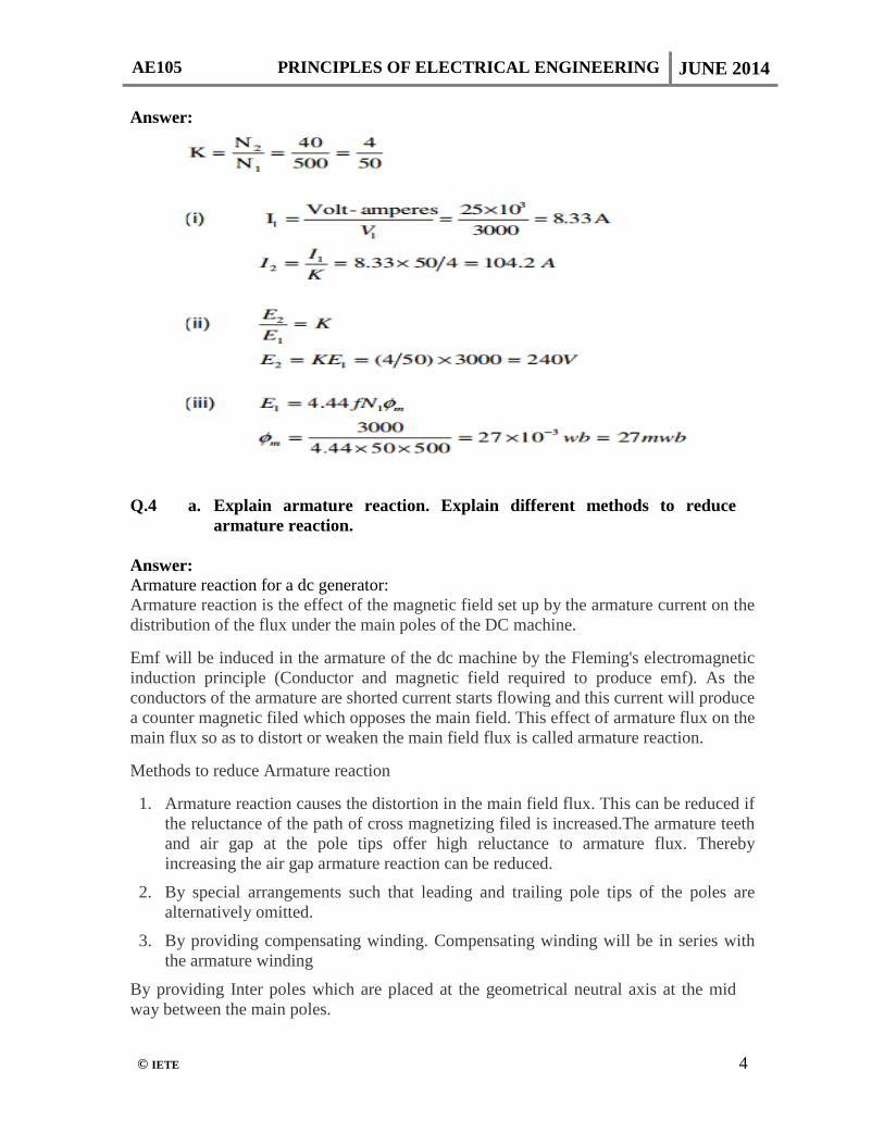
Answer:
Phasor diagram of synchronous generator with inductive load (lagging p.f.)

AE105 PRINCIPLES OF ELECTRICAL ENGINEERING JUNE 2014
© IETE 7
AE105 PRINCIPLES OF ELECTRICAL ENGINEERING JUNE 2014
© IETE 8
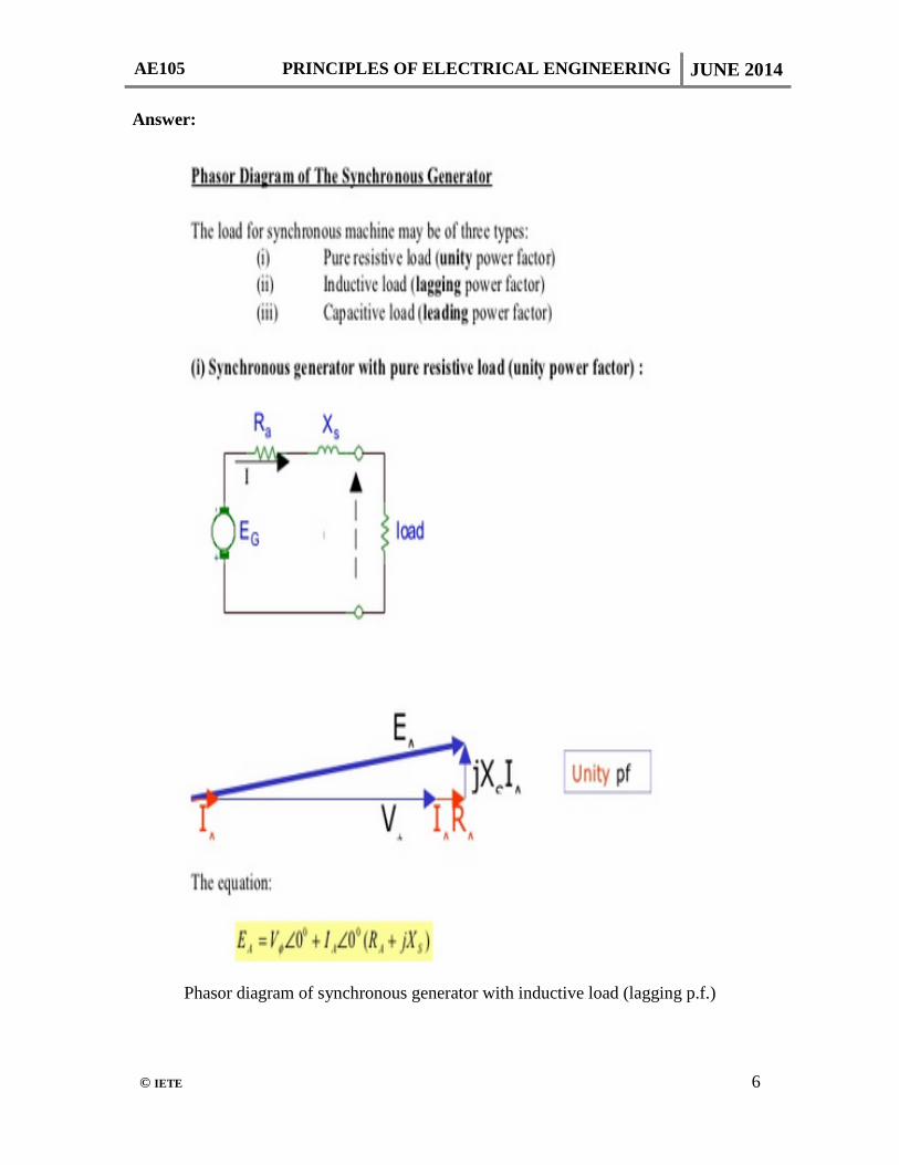
b. A 3300 Volts, delta connected motor has a synchronous reactance per phase (delta) of 18 ohm. It operates at a leading power factor of 0.707 when drawing 800 kW from the mains. Calculate its excitation emf.
Answer: Given VL =Vph = 3300V ; cosΦ = 0.707 leading ; Pi =800 kw = √3 VLIL cosΦ
∴IL = 800 x 103/ √3 x3300 x 0.707 Iph = IL /√3 = 114.30 Amp. Now, excitation e.m.f (E0) will be : E0 =√ (Vph cosΦ)2 + (Vph sinΦ + IphXph) 2
=√ (3300 x 0.707)2 + (3300 x 0.707+ 114.3 x 18)2 =4.9712 x 10³ or 4971.22 Volts
A 3300 Volts, delta connected motor has a synchronous reactance per
phase (delta) of 18 ohm. It operates at a leading power factor of 0.707 when drawing 800 kW from the mains. Calculate its excitation emf.
Q.6 a. Draw the torque speed characteristics of a 3-phase induction machine
and clearly indicate the effect of change in rotor resistance on characteristics of motor.
Answer: The Thevenin equivalent of an induction motor circuit model is given in Figure D1

AE105 PRINCIPLES OF ELECTRICAL ENGINEERING JUNE 2014
© IETE 9
The torque developed can be expressed as
The torque speed characteristics [or, characteristics] can be obtained from Equation (A); for different values of rotor resistance are shown in Fig.D2

AE105 PRINCIPLES OF ELECTRICAL ENGINEERING JUNE 2014
© IETE 10
b. If the motor is fed from a 50 Hz 3 phase supply and its synchronous speed is 1000 RPM and full load speed is 950 RPM, calculate
(i) number of poles (ii) slip at full load (iii) frequency of rotor voltage (iv) speed of rotor field wrt rotor (v) speed of rotor field wrt to stator (vi) speed of rotor field wrt stator field (vii) speed of rotor at a slip of 10 percent Answer: If the motor is fed from a 50 Hz 3 phase line, calculate (i) number of poles (ii) slip at full load (iii) frequency of rotor voltage (iv) speed of rotor field wrt rotor (v) speed of rotor field wrt to stator (vi) speed of rotor field wrt stator field (vii) speed of rotor at a slip of 10 percent. Q.7 a. Why auxiliary winding is required in single phase motors? Discuss
field of applications of fractional kW motors. Answer: Working: Construction of a single -phase induction motor is similar to that of a three -phase induction motor except that the stator is provided with a single- phase winding. Thus, it has a stator with slots, and squirrel cage rotor with a small air-gap in between. When it is connected to single- phase ac supply, alternating current flows in its stator winding and the polarity of stator poles would alternately be N and S. The field so produced will be pulsating i.e. polarities will be alternating with the flux rising and falling in strength. The current induced in the rotor will tend to turn it in both directions alternately and thus the rotor will be at standstill due to inertia. If rotor is given a push by hand or by another means in any direction, it will rotate in the same direction developing operating torque. Thus a single –phase induction is not self- starting and requires special starting means. Applications: Due to their relatively simple construction, availability in variety of designs, and characteristics and promoted by economics as well as meeting the special requirements,single-phase induction motors are widely used, particularly where fractional horse power range is less than 2 H.P. For example motors in 1/8 to 3/4 H.P. ranges are used in fans, refrigerators, washing machines, blowers, centrifugal pumps, 1/30 to 1/20 H.P. range, are used in toys, hair dryers, vending machines, etc.

AE105 PRINCIPLES OF ELECTRICAL ENGINEERING JUNE 2014
© IETE 11
b. With a neat diagram explain the working of a universal motor. Also draw its torque-speed characteristics when it is fed from both ac & dc sources.
Answer: Universal motor:-
A universal motor develops unidirectional torque regardless of whether they operate on DC or AC supply. The production of unidirectional torque when the motor runs on AC supply can be understood from the above figures. The motor works on the same principle as a DC motor i.e. force between the main pole flux and the current carrying armature conductors. This is true regardless of whether the current is alternating or direct. The rotor is same in construction to that of a DC motor but the stator is laminated necessarily because the flux is alternating when the motor is operated from AC supply. Torque speed characteristics:-
AE105 PRINCIPLES OF ELECTRICAL ENGINEERING JUNE 2014
© IETE 12
Q.8 a. What are the various merits and limitation of HVDC transmission over the conventional AC transmission?
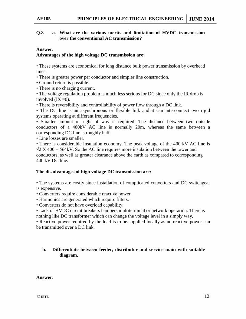
Answer: Advantages of the high voltage DC transmission are: • These systems are economical for long distance bulk power transmission by overhead lines. • There is greater power per conductor and simpler line construction. • Ground return is possible. • There is no charging current. • The voltage regulation problem is much less serious for DC since only the IR drop is involved (IX =0). • There is reversibility and controllability of power flow through a DC link. • The DC line is an asynchronous or flexible link and it can interconnect two rigid systems operating at different frequencies. • Smaller amount of right of way is required. The distance between two outside conductors of a 400kV AC line is normally 20m, whereas the same between a corresponding DC line is roughly half. • Line losses are smaller. • There is considerable insulation economy. The peak voltage of the 400 kV AC line is √2 X 400 = 564kV. So the AC line requires more insulation between the tower and conductors, as well as greater clearance above the earth as compared to corresponding 400 kV DC line. The disadvantages of high voltage DC transmission are: • The systems are costly since installation of complicated converters and DC switchgear is expensive. • Converters require considerable reactive power. • Harmonics are generated which require filters. • Converters do not have overload capability. • Lack of HVDC circuit breakers hampers multiterminal or network operation. There is nothing like DC transformer which can change the voltage level in a simply way. • Reactive power required by the load is to be supplied locally as no reactive power can be transmitted over a DC link. b. Differentiate between feeder, distributor and service main with suitable
diagram. Answer:

AE105 PRINCIPLES OF ELECTRICAL ENGINEERING JUNE 2014
© IETE 13
Fig K1 shows a typical distribution system consisting of various kinds of substations and feeders, finally ending up with consumer’s service lines. The sequence, as shown in the figure, is as follows: Firstly sub-transmission lines at 66KV emanate from a transmission substation. A distribution transformer at the 66 KV substation steps down this voltage from 66KV to 11KV, that is, the primary feeder voltage. At the distribution substation transformer this (11KV) is further stepped down to 415 V which is the voltage of the consumer’s services lines.
Q.9 a. Write name of different type of ear thing. How it works? Answer: Fig K1 shows a typical distribution system consisting of various kinds of substations and feeders, finally ending up with consumer’s service lines. The sequence, as shown in the figure, is as follows: Firstly sub-transmission lines at 66KV emanate from a transmission substation. A distribution transformer at the 66 KV substation steps down this voltage from 66KV to 11KV, that is, the primary feeder voltage. At the distribution substation transformer this (11KV) is further stepped down to 415 V which is the voltage of the consumer’s services lines.
AE105 PRINCIPLES OF ELECTRICAL ENGINEERING JUNE 2014
© IETE 14
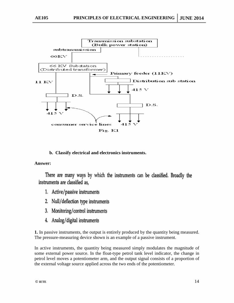
b. Classify electrical and electronics instruments. Answer:
1. In passive instruments, the output is entirely produced by the quantity being measured. The pressure-measuring device shown is an example of a passive instrument. In active instruments, the quantity being measured simply modulates the magnitude of some external power source. In the float-type petrol tank level indicator, the change in petrol level moves a potentiometer arm, and the output signal consists of a proportion of the external voltage source applied across the two ends of the potentiometer.

AE105 PRINCIPLES OF ELECTRICAL ENGINEERING JUNE 2014
© IETE 15
2. In null-type instruments, the physically effect caused by the quantity being measured in nullified by generating an equivalent opposing effect. the equivalent null causing effect then provides a measure of the unknown quantity. A deflection type instrument is that in which the physical effect generated by the measuring quantity is noted and correlated to the measured. 3.
4. The signals of an analog unit vary in a continuous fashion and can take on infinite number values in a given range. Wrist watch, speedometer of an automobile, fuel gauge, ammeters and voltmeters are examples of analog instruments. The digital instruments convert a measured analog voltage into digital quantity which is displayed numerically, usually by neon indicator tubes. The output may either be a digit for every successive increment of the input or be a coded discrete signal representative of the numerical value of the input.
TEXT BOOK
Basic Electrical Engineering, D. P. Kothari & I. J. Nagrath, Tata McGraw-Hill Publishing Company Limited, 3rd Edition, 4th Reprint 2011.