Embed Size (px)
Citation preview
1© 2015 Emerson Climate Technologies, Inc.
AE8-1405 R2
AE8-1405 R2
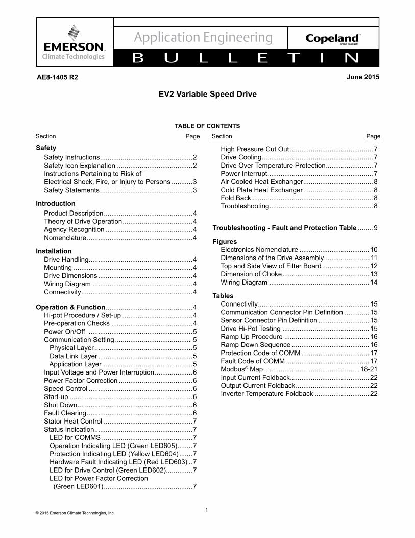
EV2 Variable Speed Drive
Safety Safety Instructions .................................................2 Safety Icon Explanation ........................................2 Instructions Pertaining to Risk of Electrical Shock, Fire, or Injury to Persons ...........3 Safety Statements .................................................3
Introduction Product Description ...............................................4 Theory of Drive Operation .....................................4 Agency Recognition ..............................................4 Nomenclature ........................................................4
Installation Drive Handling .......................................................4 Mounting ...............................................................4 Drive Dimensions ..................................................4 Wiring Diagram .....................................................4 Connectivity ...........................................................4
Operation & Function ..............................................4 Hi-pot Procedure / Set-up .....................................4 Pre-operation Checks ...........................................4 Power On/Off .......................................................5 Communication Setting ........................................ 5 Physical Layer ....................................................5 Data Link Layer ..................................................5 Application Layer ................................................5 Input Voltage and Power Interruption ....................6 Power Factor Correction .......................................6 Speed Control .......................................................6 Start-up .................................................................6 Shut Down .............................................................6 Fault Clearing ........................................................6 Stator Heat Control ...............................................7 Status Indication ....................................................7 LED for COMMS ................................................7 Operation Indicating LED (Green LED605) ........7 Protection Indicating LED (Yellow LED604) .......7 Hardware Fault Indicating LED (Red LED603) ..7 LED for Drive Control (Green LED602) ..............7 LED for Power Factor Correction (Green LED601) ...............................................7
High Pressure Cut Out ............................................7 Drive Cooling ...........................................................7 Drive Over Temperature Protection .........................7 Power Interrupt ........................................................7 Air Cooled Heat Exchanger .....................................8 Cold Plate Heat Exchanger .....................................8 Fold Back ................................................................8 Troubleshooting .......................................................8
Troubleshooting - Fault and Protection Table ........ 9
Figures Electronics Nomenclature .....................................10 Dimensions of the Drive Assembly ........................ 11 Top and Side View of Filter Board .........................12 Dimension of Choke ..............................................13 Wiring Diagram .....................................................14
Tables Connectivity ...........................................................15 CommunicationConnectorPinDefinition .............15 SensorConnectorPinDefinition ...........................15 Drive Hi-Pot Testing ..............................................15 Ramp Up Procedure .............................................16 Ramp Down Sequence .........................................16 Protection Code of COMM ....................................17 Fault Code of COMM ............................................17 Modbus® Map ..................................................18-21 Input Current Foldback ..........................................22 Output Current Foldback .......................................22 Inverter Temperature Foldback .............................22
TABLE OF CONTENTSSection Page Section Page
June 2015
2© 2015 Emerson Climate Technologies, Inc.
AE8-1405 R2
Safety InstructionsCopeland Scroll™ variable speed drives are manufactured according to the latest U.S. and European Safety Standards. Particular emphasis has been placed on the user's safety. Safety icons are explained below and safety instructions applicable to the products in this bulletin are grouped on page 3. These instructions should be retained throughout the lifetime of the drive. You are strongly advised to follow these safety instructions.
Safety Instructions Copeland Scroll™ compressors are manufactured according to the latest U.S. and European Safety Standards. Particular emphasis has been placed on the user's safety. Safey icons are explained below and safety instructions applicable to the products in this bulletin are grouped on Page 3. These instructions should be retained throughout the lifetime of the compessor. You are strongly advised to follow these safety instructions.
Safety Icon Explanation
DANGER indicates a hazardous situation which, if not avoided, will result in death or serious injury.
WARNING indicates a hazardous situation which, if not avoided, could result in death or serious injury.
CAUTION, used with the safety alert symbol, indicates a hazardous situation which, if not avoided, could result in minor or moderate injury.
NOTICE is used to address practices not related to personal injury.
CAUTION, without the safety alert symbol, is used to address practices not related to personal injury.
DANGER
WARNING
CAUTION
NOTICE
CAUTION
3© 2015 Emerson Climate Technologies, Inc.
AE8-1405 R2
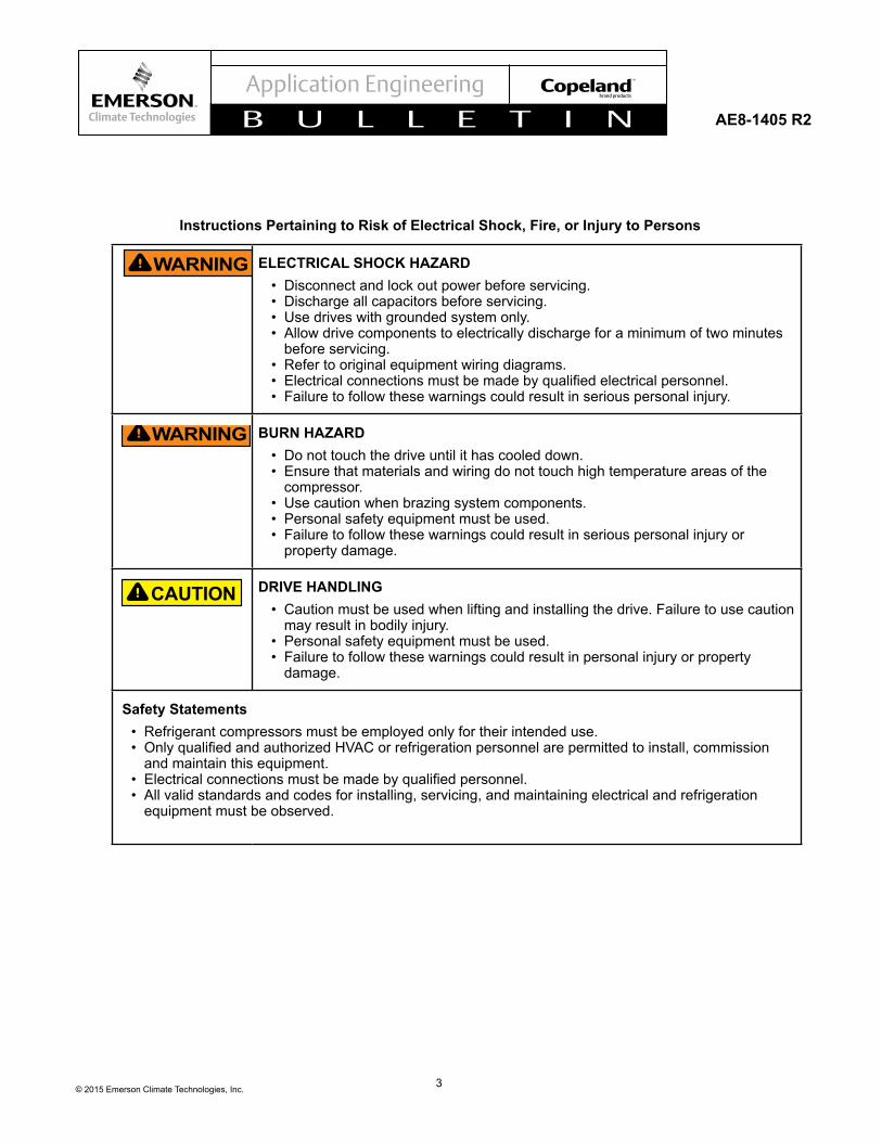
ELECTRICAL SHOCK HAZARD• Disconnect and lock out power before servicing.• Discharge all capacitors before servicing.• Use drives with grounded system only.• Allow drive components to electrically discharge for a minimum of two minutes
before servicing.• Refer to original equipment wiring diagrams.• Electricalconnectionsmustbemadebyqualifiedelectricalpersonnel.• Failure to follow these warnings could result in serious personal injury.
BURN HAZARD• Do not touch the drive until it has cooled down.• Ensure that materials and wiring do not touch high temperature areas of the
compressor.• Use caution when brazing system components.• Personal safety equipment must be used.• Failure to follow these warnings could result in serious personal injury or
property damage.
DRIVE HANDLING• Caution must be used when lifting and installing the drive. Failure to use caution
may result in bodily injury.• Personal safety equipment must be used.• Failure to follow these warnings could result in personal injury or property
damage.
Safety Statements• Refrigerant compressors must be employed only for their intended use.• OnlyqualifiedandauthorizedHVACorrefrigerationpersonnelarepermittedtoinstall,commission
and maintain this equipment.• Electricalconnectionsmustbemadebyqualifiedpersonnel.• All valid standards and codes for installing, servicing, and maintaining electrical and refrigeration
equipment must be observed.
Instructions Pertaining to Risk of Electrical Shock, Fire, or Injury to Persons
CAUTION
WARNING
WARNING
4© 2015 Emerson Climate Technologies, Inc.
AE8-1405 R2
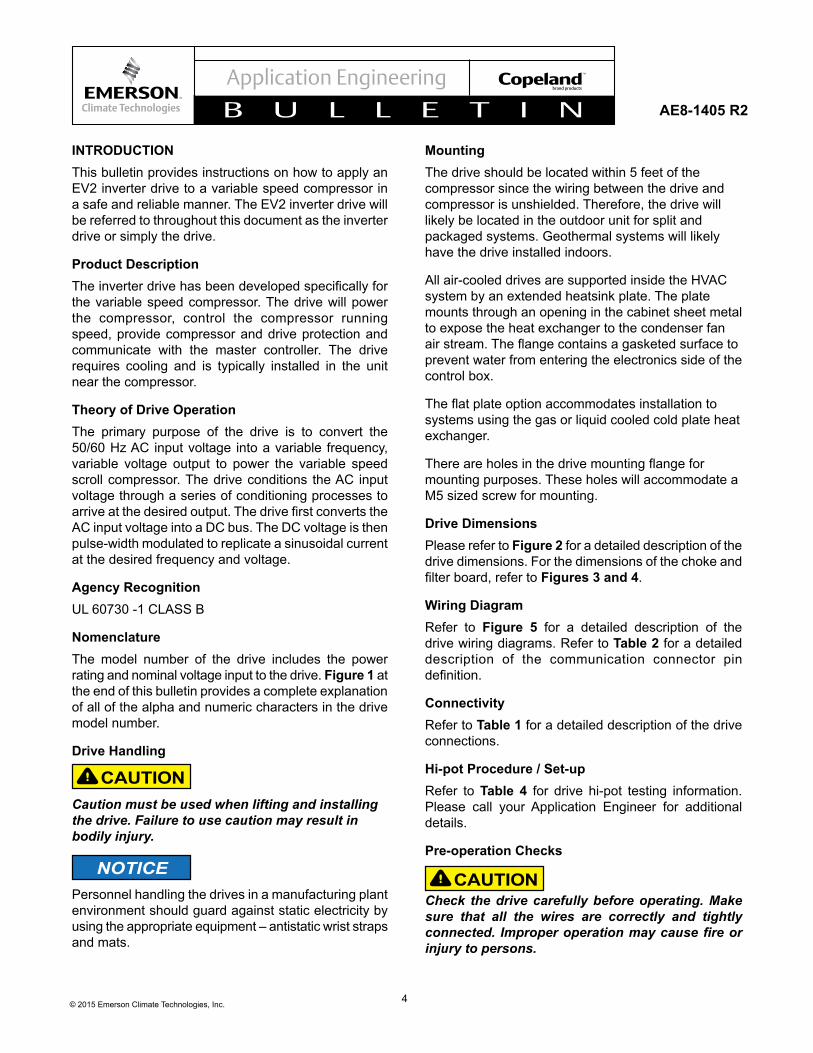
INTRODUCTIONThis bulletin provides instructions on how to apply an EV2 inverter drive to a variable speed compressor in a safe and reliable manner. The EV2 inverter drive will be referred to throughout this document as the inverter drive or simply the drive.
Product DescriptionTheinverterdrivehasbeendevelopedspecificallyforthe variable speed compressor. The drive will power the compressor, control the compressor running speed, provide compressor and drive protection and communicate with the master controller. The drive requires cooling and is typically installed in the unit near the compressor.
Theory of Drive Operation The primary purpose of the drive is to convert the 50/60 Hz AC input voltage into a variable frequency, variable voltage output to power the variable speed scroll compressor. The drive conditions the AC input voltage through a series of conditioning processes to arriveatthedesiredoutput.ThedrivefirstconvertstheAC input voltage into a DC bus. The DC voltage is then pulse-width modulated to replicate a sinusoidal current at the desired frequency and voltage.
Agency Recognition UL 60730 -1 CLASS B
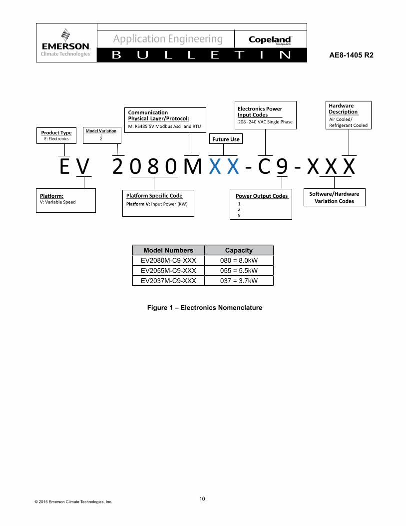
Nomenclature The model number of the drive includes the power rating and nominal voltage input to the drive. Figure 1 at the end of this bulletin provides a complete explanation of all of the alpha and numeric characters in the drive model number.
Drive Handling
CAUTIONCaution must be used when lifting and installing the drive. Failure to use caution may result in bodily injury.
NOTICEPersonnel handling the drives in a manufacturing plant environment should guard against static electricity by using the appropriate equipment – antistatic wrist straps and mats.
MountingThe drive should be located within 5 feet of the compressor since the wiring between the drive and compressor is unshielded. Therefore, the drive will likely be located in the outdoor unit for split and packaged systems. Geothermal systems will likely have the drive installed indoors.
All air-cooled drives are supported inside the HVAC system by an extended heatsink plate. The plate mounts through an opening in the cabinet sheet metal to expose the heat exchanger to the condenser fan airstream.Theflangecontainsagasketedsurfacetoprevent water from entering the electronics side of the control box.
Theflatplateoptionaccommodatesinstallationtosystems using the gas or liquid cooled cold plate heat exchanger.
Thereareholesinthedrivemountingflangeformounting purposes. These holes will accommodate a M5 sized screw for mounting.
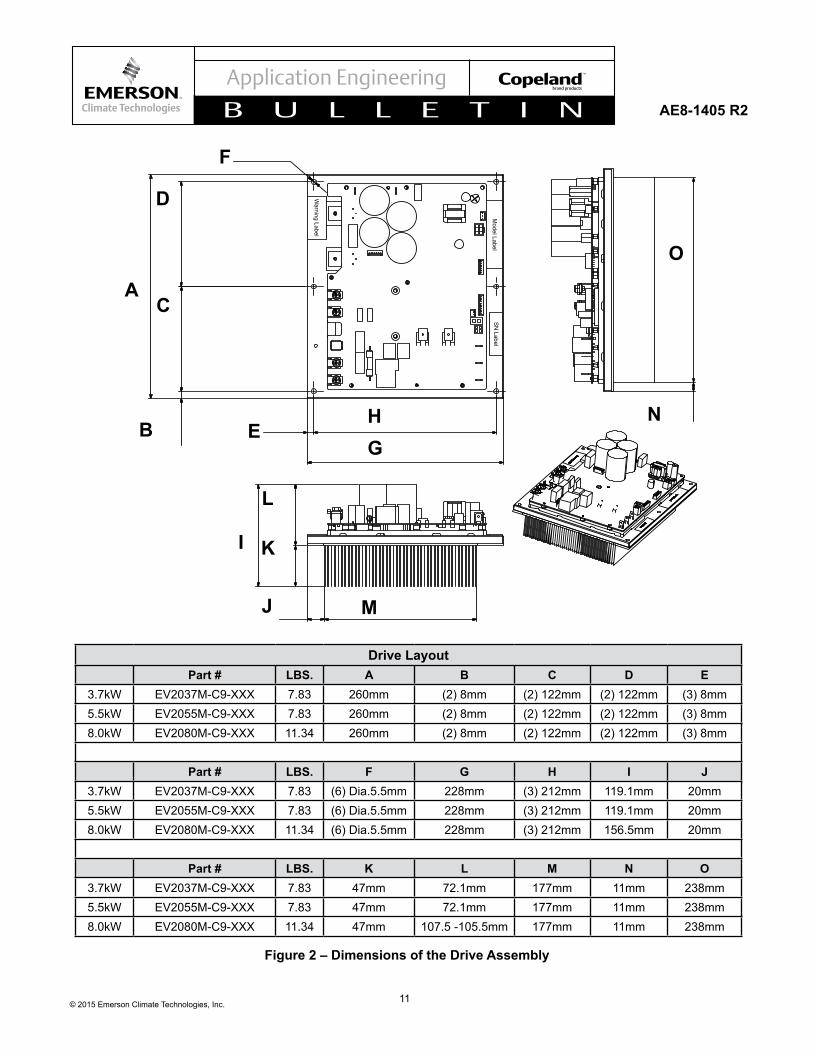
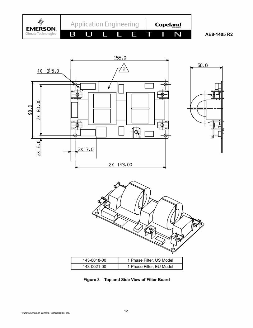
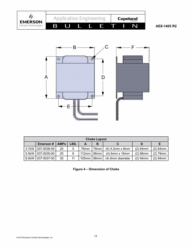
Drive Dimensions Please refer to Figure 2 for a detailed description of the drive dimensions. For the dimensions of the choke and filterboard,refertoFigures 3 and 4.
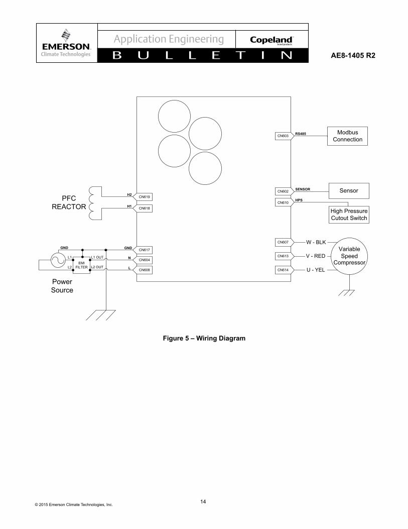
Wiring Diagram Refer to Figure 5 for a detailed description of the drive wiring diagrams. Refer to Table 2 for a detailed description of the communication connector pin definition.
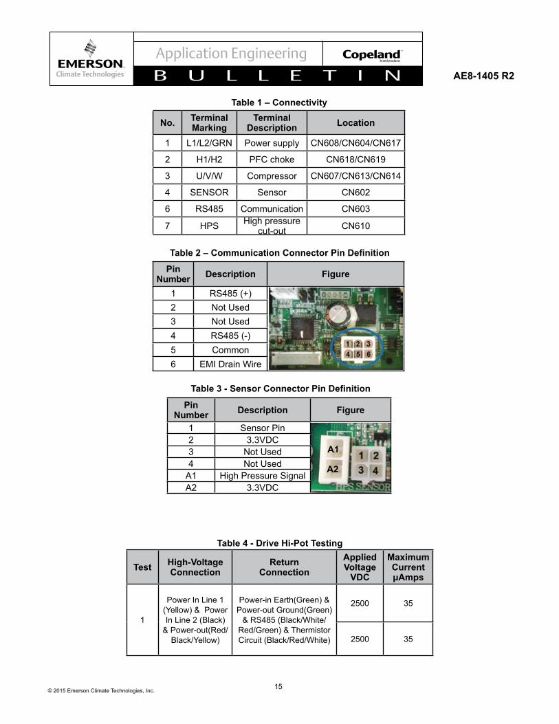
Connectivity Refer to Table 1 for a detailed description of the drive connections.
Hi-pot Procedure / Set-upRefer to Table 4 for drive hi-pot testing information. Please call your Application Engineer for additional details.
Pre-operation Checks
CAUTIONCheck the drive carefully before operating. Make sure that all the wires are correctly and tightly connected. Improper operation may cause fire or injury to persons.
5© 2015 Emerson Climate Technologies, Inc.
AE8-1405 R2
Power On/Off
NOTICEThe drive should use rated AC power supply: 50/60Hz, 208~240V. Using incorrect power supply may cause the drive to be damaged. Users should check the power supply before powering on the drive.
When powering off the drive, make sure the compressor is not running.
Communication Setting The drive is designed to be used in a master-slave configurationwherethemasterisasystemcontroller.Two standard Modbus® protocols are available: RTU and ASCII.
Users can select RTU Mode or ASCII Mode by writing the value of related register according to the Modbus Map. For example, to select the RTU Mode under ASCII Mode, write 0x2345 passwords to Register 200 to get ModbusMapAccessfirst,andthenwrite0002Htotheregister 201. Power off the drive and repower on again, and then the communication mode will be changed to RTU mode. On 201-204, the end user can change baud rate, slave ID, and parity using the register information table. 205 must be set to distinguish compressor model variations.
Users can also change the baud rate, parity and stop bit method. Detailed parameters are in the Modbus Map.
Modbus uses a three layer protocol – physical, data link, and application.
Physical Layer The physical layer defines the hardware interfaceto the master. The standard control interface uses a two wire serial communication (RS485 physical layer) scheme. The recommended cable is an 18 AWG stranded copper with 4 conductors and a drain wire.
Data Link Layer Thedatalinklayerdefinesthereliabletransferofamessage transferred from the master to one of the slave devices, and the reliable transfer of the response message back to the master. The drive code sets the default node address of 045 for Modbus RTU and 01 for Modbus ASCII. The desired bit rate communication is 19200 for RTU and 38400 for ASCII.
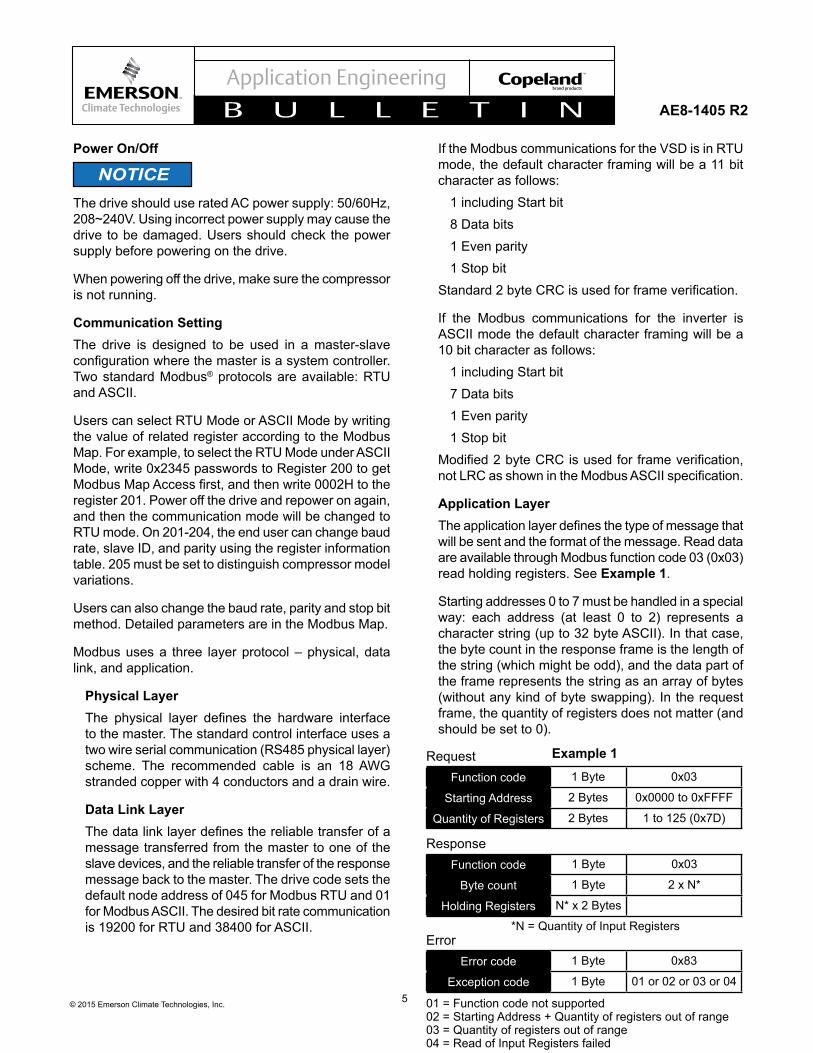
If the Modbus communications for the VSD is in RTU mode, the default character framing will be a 11 bit character as follows:
1 including Start bit8 Data bits1 Even parity1 Stop bit
Standard2byteCRCisusedforframeverification.
If the Modbus communications for the inverter is ASCII mode the default character framing will be a 10 bit character as follows:
1 including Start bit7 Data bits1 Even parity1 Stop bit
Modified2byteCRCisusedforframeverification,notLRCasshownintheModbusASCIIspecification.
Application Layer Theapplicationlayerdefinesthetypeofmessagethatwill be sent and the format of the message. Read data are available through Modbus function code 03 (0x03) read holding registers. See Example 1.
Starting addresses 0 to 7 must be handled in a special way: each address (at least 0 to 2) represents a character string (up to 32 byte ASCII). In that case, the byte count in the response frame is the length of the string (which might be odd), and the data part of the frame represents the string as an array of bytes (without any kind of byte swapping). In the request frame, the quantity of registers does not matter (and should be set to 0).
RequestFunction code 1 Byte 0x03
Starting Address 2 Bytes 0x0000 to 0xFFFF
Quantity of Registers 2 Bytes 1 to 125 (0x7D)
ResponseFunction code 1 Byte 0x03
Byte count 1 Byte 2 x N*
Holding Registers N* x 2 Bytes *N = Quantity of Input RegistersError
Error code 1 Byte 0x83
Exception code 1 Byte 01 or 02 or 03 or 04 01 = Function code not supported02 = Starting Address + Quantity of registers out of range03 = Quantity of registers out of range04 = Read of Input Registers failed
Example 1
6© 2015 Emerson Climate Technologies, Inc.
AE8-1405 R2
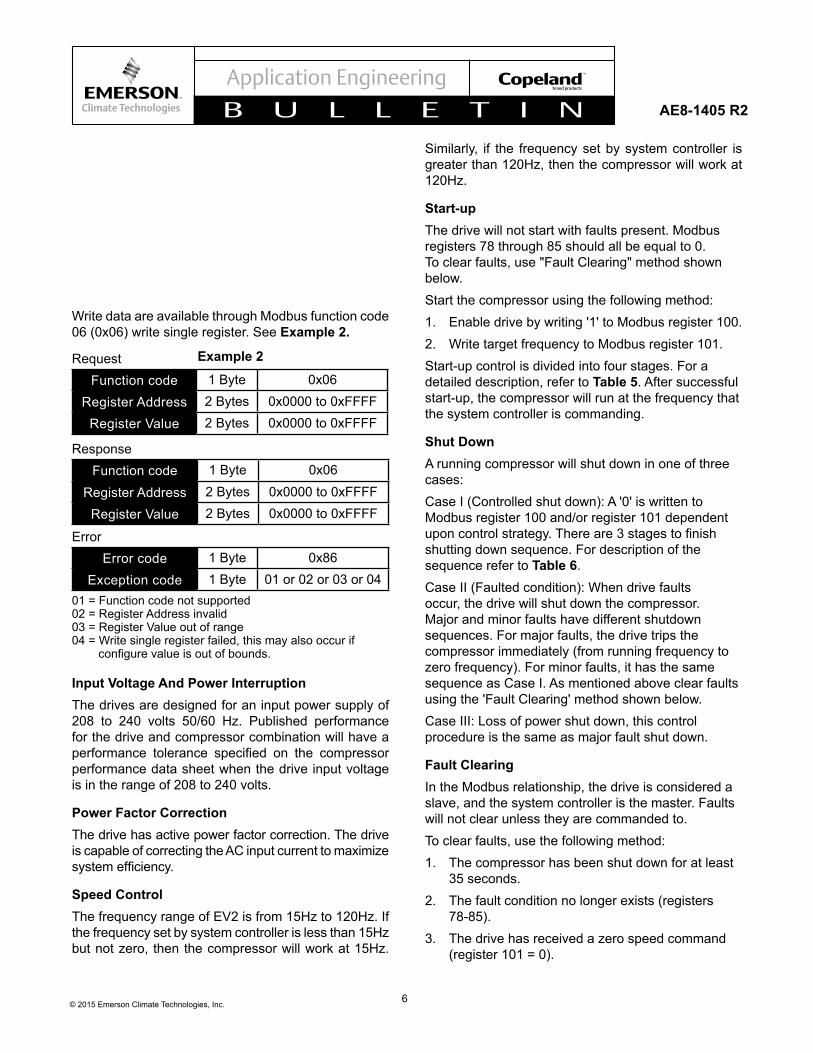
Write data are available through Modbus function code 06 (0x06) write single register. See Example 2.
RequestFunction code 1 Byte 0x06
Register Address 2 Bytes 0x0000 to 0xFFFF
Register Value 2 Bytes 0x0000 to 0xFFFF
ResponseFunction code 1 Byte 0x06
Register Address 2 Bytes 0x0000 to 0xFFFF
Register Value 2 Bytes 0x0000 to 0xFFFF Error
Error code 1 Byte 0x86
Exception code 1 Byte 01 or 02 or 03 or 04 01 = Function code not supported02 = Register Address invalid03 = Register Value out of range04 = Write single register failed, this may also occur if configurevalueisoutofbounds.
Example 2
Input Voltage And Power Interruption The drives are designed for an input power supply of 208 to 240 volts 50/60 Hz. Published performance for the drive and compressor combination will have a performance tolerance specified on the compressorperformance data sheet when the drive input voltage is in the range of 208 to 240 volts.
Power Factor Correction The drive has active power factor correction. The drive is capable of correcting the AC input current to maximize systemefficiency.
Speed Control The frequency range of EV2 is from 15Hz to 120Hz. If the frequency set by system controller is less than 15Hz but not zero, then the compressor will work at 15Hz.
Similarly, if the frequency set by system controller is greater than 120Hz, then the compressor will work at 120Hz.
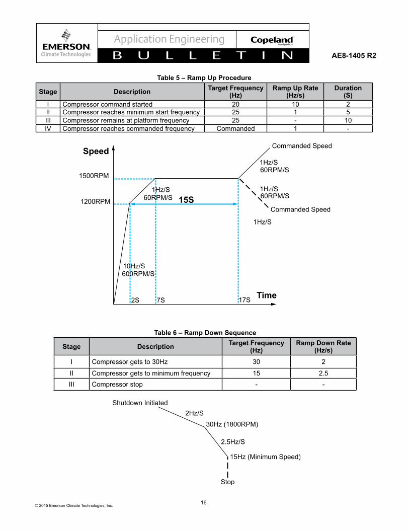
Start-upThe drive will not start with faults present. Modbus registers 78 through 85 should all be equal to 0. To clear faults, use "Fault Clearing" method shown below. Start the compressor using the following method:1. Enable drive by writing '1' to Modbus register 100.2. Write target frequency to Modbus register 101.Start-up control is divided into four stages. For a detailed description, refer to Table 5. After successful start-up, the compressor will run at the frequency that the system controller is commanding.
Shut DownA running compressor will shut down in one of three cases:Case I (Controlled shut down): A '0' is written to Modbus register 100 and/or register 101 dependent uponcontrolstrategy.Thereare3stagestofinishshutting down sequence. For description of the sequence refer to Table 6.Case II (Faulted condition): When drive faults occur, the drive will shut down the compressor. Major and minor faults have different shutdown sequences. For major faults, the drive trips the compressor immediately (from running frequency to zero frequency). For minor faults, it has the same sequence as Case I. As mentioned above clear faults using the 'Fault Clearing' method shown below. Case III: Loss of power shut down, this control procedure is the same as major fault shut down.
Fault Clearing In the Modbus relationship, the drive is considered a slave, and the system controller is the master. Faults will not clear unless they are commanded to. To clear faults, use the following method:1. The compressor has been shut down for at least
35 seconds.2. The fault condition no longer exists (registers
78-85).3. The drive has received a zero speed command
(register 101 = 0).
7© 2015 Emerson Climate Technologies, Inc.
AE8-1405 R2
4. The drive has been disabled (register 100 = 0).5. Write '1' to register 103.Faults will not clear unless all items above are true.
Stator Heat Control In actual use, the system controller may decide whether to preheat or not according to the environment. When preheating is needed, the system controller sends register 100 a compressor enable command and register 102 a stator heating power value. The drive transmits up to 50W DC power to warm up the compressor.
The stator heating is on if the following are true: 1. There are no active errors. 2. Compressor enabled. 3. Compressor speed is set zero. 4. Stator heater power setting is from 10~50.
If the system sends a speed demand to the drive while the stator is heating, the drive will stop stator heating and start the compressor. While running, if the system sends a zero speed command, the drive will shut down the compressor automatically, and then resume the stator heating to the value saved in Stator Heater Power Memory Register (a value or zero = off).
Status Indication There are three LED for status display with:
LED for COMMS Operation Indicating LED (Green LED605) When the drive is in normal state (no protection and fault), the drive is in standby state and the compressor is not running, the LED will blink at 0.5Hz frequency. If the compressor is running, the LED will always be on.
Protection Indicating LED (Yellow LED604) When the drive is under protection, the yellow LED will blink. Refer to the Troubleshooting section of this bulletin for more information.
Hardware Fault Indicating LED (Red LED603) When the drive is under hardware fault, the red LED will blink. Refer to Troubleshooting for more information.
LED for Drive Control (Green LED602) When the drive is in normal state, whether the compressor is running or standby, the LED will blink
at 1Hz frequency. When the drive is under protection or hardware fault, the LED will blink at 8Hz frequency.
N - Yellow LED = PROTECTIONN - Red LED = FAULT
LED for Power Factor Correction (Green LED601) PFC control circuit has a LED indicator (Green). The status of the LED is only related with PFC.
When the drive PFC is not in operation, the LED will blink at 1Hz frequency. When the PFC is in operation, the LED will be on.
High Pressure Cut OutCN610 is a 2 port connector. The output is a 3.3VDC signal. The high pressure cutout switch must be normally closed. If the switch is open, the drive will not operate.
Drive Cooling Because of the power electronics used in the drive and the associated heat generation, drive cooling is required to keep the drive components in their design temperature range. The allowable temperature range of the drive (not the ambient air surrounding the drive) is -13°F to 150°F. Drive temperature should be monitored during system development and during system extreme conditions to ensure that the maximum allowable drive temperature isn’t exceeded. The highest drive temperature will typically occurs during high load conditions and/or during high drive ambients. The drive is internally protected against overheating and will shut itself down if overheating or foldback occurs.
Drive Over Temperature Protection The drive is self protected against high internal temperatures. The drive will perform a controlled shutdown if a high temperature condition is detected. When the internal drive temperature decreases to a safe level the temperature fault condition will clear and the drive will restart the compressor.
Power Interrupt Power interrupts can result in a drive trip that won't harm the drive. The drive can withstand interrupts of a short duration (<= 10 mS), but will trip on anything longer.
Air Cooled Heat Exchanger
8© 2015 Emerson Climate Technologies, Inc.
AE8-1405 R2
Drives cooled by the aluminum air cooled heat exchangeraredesignedtobeintheairflowstreamof the condenser. The air cooled heat exchanger mustbeinstalledsothattheheatexchangerfinsareparalleltothecoolingairflow.
Cold Plate Heat Exchanger The cold plate design can be used when another cooling source is available – suction gas from the evaporator coil, subcooled liquid refrigerant, glycol solution from a geothermal loop, water from a cooling tower, etc. When refrigerant is used for drive cooling, the heat given up by the drive is transferred into the refrigeration system. This can be a net gain for heating applications and a net loss for cooling applications.
The soldering/brazing that is required to connect the cooling source to the cold plate should be performed before the cold plate is attached to the drive, to prevent overheating drive components with the torch.
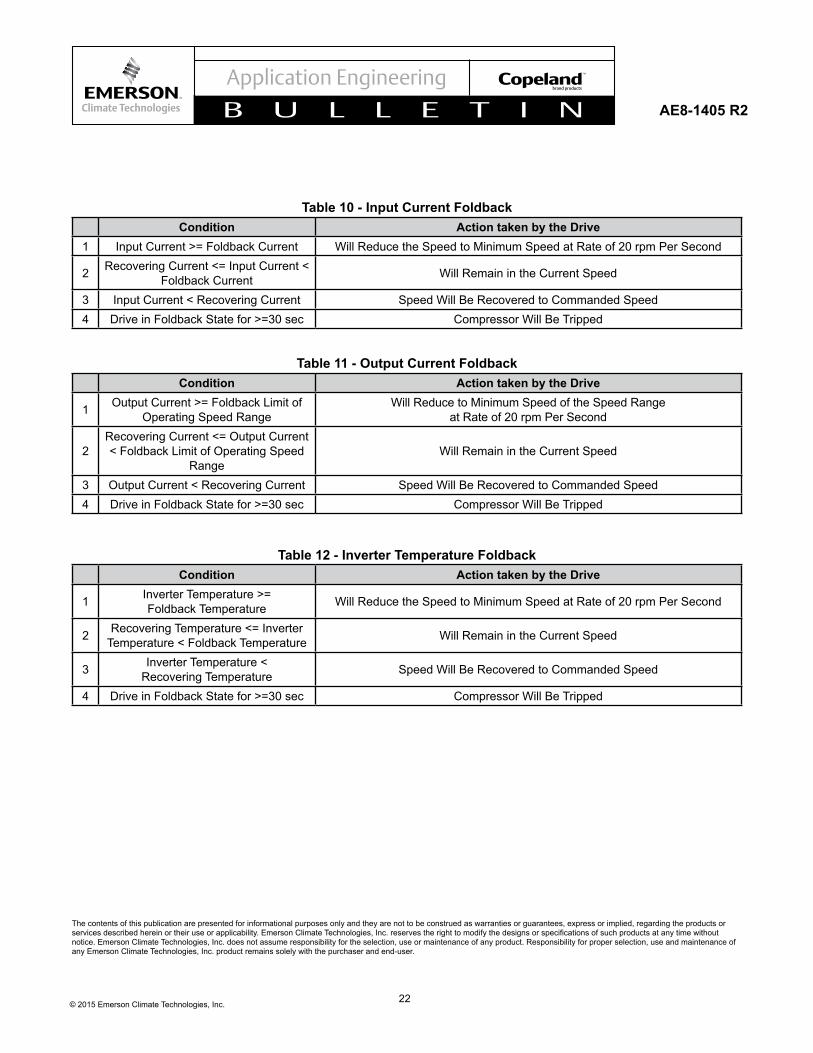
Fold BackTo protect the drive components or the compressor, the compressor speed will "fold back" or slow down to help reduce risk to components. The fold back events(s)willbeflaggedinthedrive'sModbusregisters. This will allow the operating system to respond and mitigate the conditions causing fold back.
For further information refer to Tables 10-12
TroubleshootingThe drive may indicate fault or protection for various reasons. If fault or protection occurs, users should power down the drive, check the drive, and check the drive running condition carefully. For the description, check and handling of these faults or protections, please refer to the Fault and Protection Table on the following page.
The yellow and red LED of COMM will be displayed in
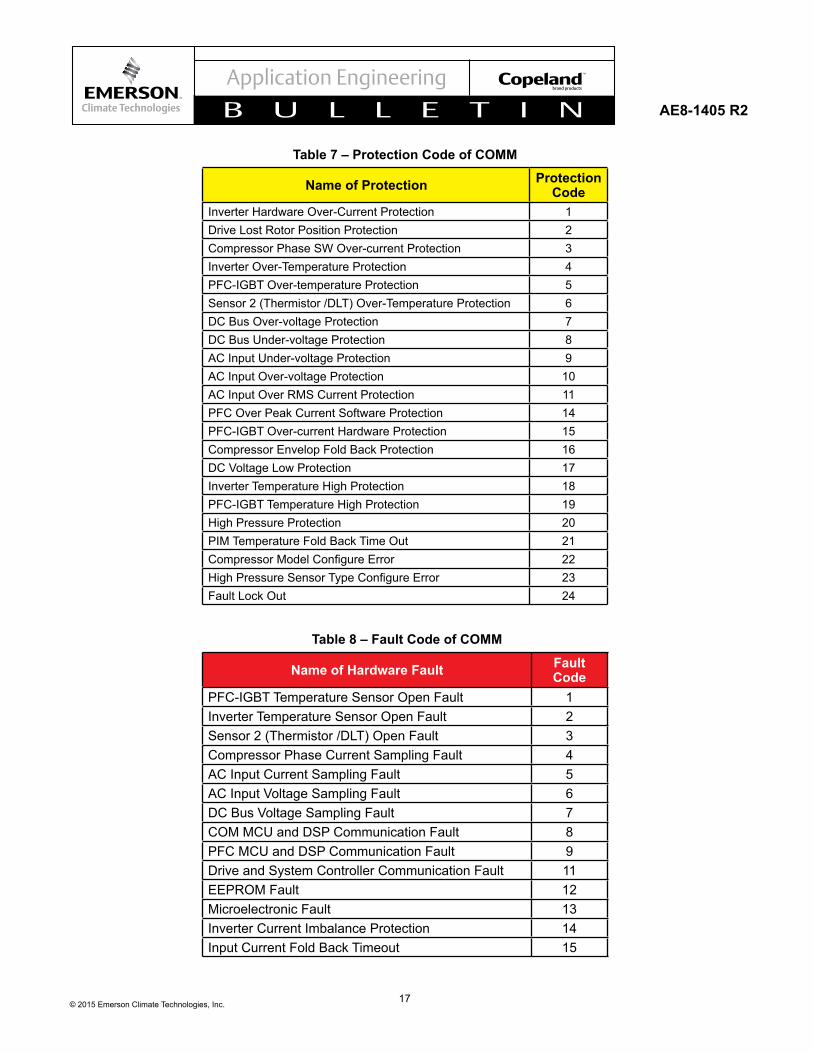
a circulation of blinking for N times (N is the protection code) then be off for 3 seconds. For detailed description of the protections, please refer to Tables 7 and 8.
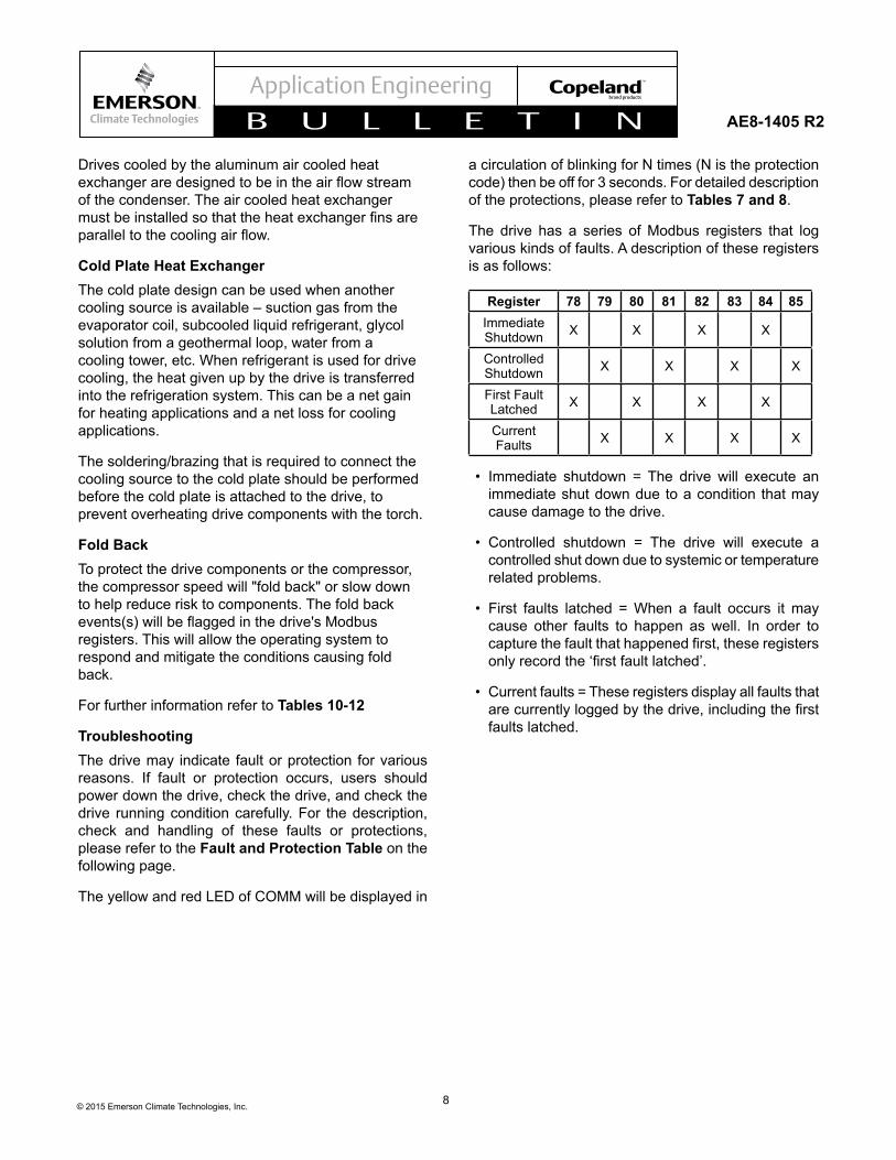
The drive has a series of Modbus registers that log various kinds of faults. A description of these registers is as follows:
Register 78 79 80 81 82 83 84 85Immediate Shutdown X X X X
Controlled Shutdown X X X X
First Fault Latched X X X X
Current Faults X X X X
• Immediate shutdown = The drive will execute an immediate shut down due to a condition that may cause damage to the drive.
• Controlled shutdown = The drive will execute a controlled shut down due to systemic or temperature related problems.
• First faults latched = When a fault occurs it may cause other faults to happen as well. In order to capturethefaultthathappenedfirst,theseregistersonlyrecordthe‘firstfaultlatched’.
• Current faults = These registers display all faults that arecurrentlyloggedbythedrive,includingthefirstfaults latched.
9© 2015 Emerson Climate Technologies, Inc.
AE8-1405 R2
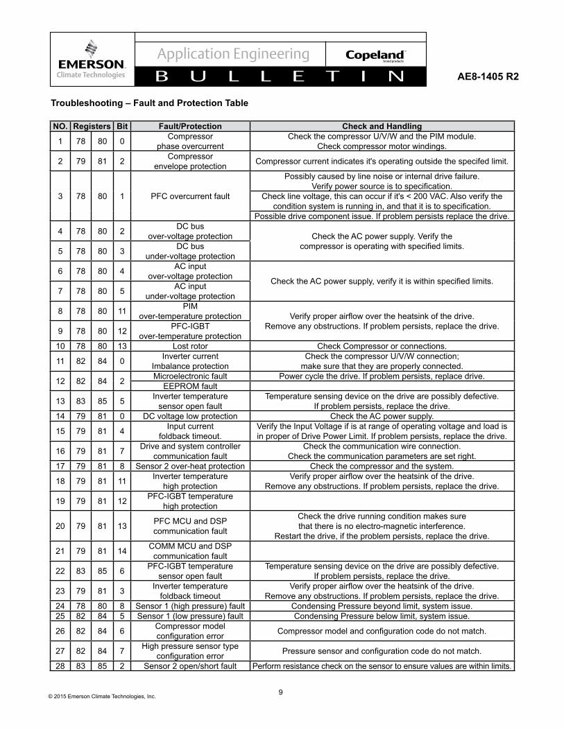
Troubleshooting – Fault and Protection Table
NO. Registers Bit Fault/Protection Check and Handling
1 78 80 0 Compressor phase overcurrent
Check the compressor U/V/W and the PIM module. Check compressor motor windings.
2 79 81 2 Compressor envelope protection Compressor current indicates it's operating outside the specifed limit.
3 78 80 1 PFC overcurrent fault
Possibly caused by line noise or internal drive failure. Verifypowersourceistospecification.
Check line voltage, this can occur if it's < 200 VAC. Also verify the conditionsystemisrunningin,andthatitistospecification.
Possible drive component issue. If problem persists replace the drive.
4 78 80 2 DC bus over-voltage protection Check the AC power supply. Verify the
compressorisoperatingwithspecifiedlimits.5 78 80 3 DC bus under-voltage protection
6 78 80 4 AC input over-voltage protection ChecktheACpowersupply,verifyitiswithinspecifiedlimits.
7 78 80 5 AC input under-voltage protection
8 78 80 11 PIM over-temperature protection Verifyproperairflowovertheheatsinkofthedrive.
Remove any obstructions. If problem persists, replace the drive.9 78 80 12 PFC-IGBT over-temperature protection
10 78 80 13 Lost rotor Check Compressor or connections.
11 82 84 0 Inverter current Imbalance protection
Check the compressor U/V/W connection; make sure that they are properly connected.
12 82 84 2 Microelectronic fault Power cycle the drive. If problem persists, replace drive.EEPROM fault
13 83 85 5 Inverter temperature sensor open fault
Temperature sensing device on the drive are possibly defective. If problem persists, replace the drive.
14 79 81 0 DC voltage low protection Check the AC power supply.
15 79 81 4 Input current foldback timeout.
Verify the Input Voltage if is at range of operating voltage and load is in proper of Drive Power Limit. If problem persists, replace the drive.
16 79 81 7 Drive and system controller communication fault
Check the communication wire connection. Check the communication parameters are set right.
17 79 81 8 Sensor 2 over-heat protection Check the compressor and the system.
18 79 81 11 Inverter temperature high protection
Verifyproperairflowovertheheatsinkofthedrive. Remove any obstructions. If problem persists, replace the drive.
19 79 81 12 PFC-IGBT temperature high protection
20 79 81 13 PFC MCU and DSP communication fault
Check the drive running condition makes sure that there is no electro-magnetic interference.
Restart the drive, if the problem persists, replace the drive.
21 79 81 14 COMM MCU and DSP communication fault
22 83 85 6 PFC-IGBT temperature sensor open fault
Temperature sensing device on the drive are possibly defective. If problem persists, replace the drive.
23 79 81 3 Inverter temperature foldback timeout
Verifyproperairflowovertheheatsinkofthedrive. Remove any obstructions. If problem persists, replace the drive.
24 78 80 8 Sensor 1 (high pressure) fault Condensing Pressure beyond limit, system issue.25 82 84 5 Sensor 1 (low pressure) fault Condensing Pressure below limit, system issue.
26 82 84 6 Compressor model configurationerror Compressormodelandconfigurationcodedonotmatch.
27 82 84 7 High pressure sensor type configurationerror Pressuresensorandconfigurationcodedonotmatch.
28 83 85 2 Sensor 2 open/short fault Perform resistance check on the sensor to ensure values are within limits.
10© 2015 Emerson Climate Technologies, Inc.
AE8-1405 R2
Model Numbers CapacityEV2080M-C9-XXX 080 = 8.0kWEV2055M-C9-XXX 055 = 5.5kWEV2037M-C9-XXX 037 = 3.7kW
Figure 1 – Electronics Nomenclature
11© 2015 Emerson Climate Technologies, Inc.
AE8-1405 R2
A
B
C
D
E
F
GH
I
J
K
L
M
N
O
Warning Label
Model Label
SN Label
Figure 2 – Dimensions of the Drive Assembly
Drive LayoutPart # LBS. A B C D E
3.7kW EV2037M-C9-XXX 7.83 260mm (2) 8mm (2) 122mm (2) 122mm (3) 8mm5.5kW EV2055M-C9-XXX 7.83 260mm (2) 8mm (2) 122mm (2) 122mm (3) 8mm8.0kW EV2080M-C9-XXX 11.34 260mm (2) 8mm (2) 122mm (2) 122mm (3) 8mm
Part # LBS. F G H I J3.7kW EV2037M-C9-XXX 7.83 (6) Dia.5.5mm 228mm (3) 212mm 119.1mm 20mm5.5kW EV2055M-C9-XXX 7.83 (6) Dia.5.5mm 228mm (3) 212mm 119.1mm 20mm8.0kW EV2080M-C9-XXX 11.34 (6) Dia.5.5mm 228mm (3) 212mm 156.5mm 20mm
Part # LBS. K L M N O3.7kW EV2037M-C9-XXX 7.83 47mm 72.1mm 177mm 11mm 238mm5.5kW EV2055M-C9-XXX 7.83 47mm 72.1mm 177mm 11mm 238mm8.0kW EV2080M-C9-XXX 11.34 47mm 107.5 -105.5mm 177mm 11mm 238mm
12© 2015 Emerson Climate Technologies, Inc.
AE8-1405 R2
Figure 3 – Top and Side View of Filter Board
143-0018-00 1 Phase Filter, US Model143-0021-00 1 Phase Filter, EU Model
13© 2015 Emerson Climate Technologies, Inc.
AE8-1405 R2
A D
B
E
FC
Figure 4 – Dimension of Choke
Choke LayoutEmerson # AMPs LBS. A B C D E
3.7kW 037-0036-00 20 5 76mm 78mm (4) 4.2mm x 8mm (2) 64mm (2) 64mm5.5kW 037-0035-00 25 6 112mm 96mm (4) 6mm x 16mm (2) 88mm (2) 79mm8.0kW 037-0037-00 30 11 105mm 96mm (4) 6mm diameter (2) 94mm (2) 84mm
14© 2015 Emerson Climate Technologies, Inc.
AE8-1405 R2
Figure 5 – Wiring Diagram
CN610
CN608
CN617
CN604
CN619
CN618
CN613
CN607
CN614
CN602
CN603
VariableSpeed
Compressor
High PressureCutout Switch
ModbusConnection
HPS
SENSOR
RS485
L
N
GND
H1
H2
EMIFILTER
Sensor
PowerSource
L1
L2
GND
PFCREACTOR
L2 OUT
L1 OUT
W - BLK
V - RED
U - YEL
15© 2015 Emerson Climate Technologies, Inc.
AE8-1405 R2
No. Terminal Marking
Terminal Description Location
1 L1/L2/GRN Power supply CN608/CN604/CN617
2 H1/H2 PFC choke CN618/CN619
3 U/V/W Compressor CN607/CN613/CN614
4 SENSOR Sensor CN602
6 RS485 Communication CN603
7 HPS High pressure cut-out CN610
Table 1 – Connectivity
Pin Number Description Figure
1 RS485 (+)2 Not Used3 Not Used4 RS485 (-)5 Common6 EMI Drain Wire
Table 2 – Communication Connector Pin Definition
A1
A2
Pin Number Description Figure
1 Sensor Pin2 3.3VDC3 Not Used4 Not Used
A1 High Pressure SignalA2 3.3VDC
Table 3 - Sensor Connector Pin Definition
Table 4 - Drive Hi-Pot Testing
Test High-Voltage Connection
Return Connection
Applied Voltage
VDC
Maximum Current μAmps
1
Power In Line 1 (Yellow) & Power In Line 2 (Black)
& Power-out(Red/Black/Yellow)
Power-in Earth(Green) & Power-out Ground(Green)
& RS485 (Black/White/Red/Green) & Thermistor Circuit (Black/Red/White)
2500 35
2500 35
16© 2015 Emerson Climate Technologies, Inc.
AE8-1405 R2
Table 6 – Ramp Down Sequence
Stage Description Target Frequency (Hz)
Ramp Down Rate (Hz/s)
I Compressor gets to 30Hz 30 2
II Compressor gets to minimum frequency 15 2.5III Compressor stop - -
Table 5 – Ramp Up Procedure
Stage Description Target Frequency (Hz)
Ramp Up Rate (Hz/s)
Duration (S)
I Compressor command started 20 10 2II Compressor reaches minimum start frequency 25 1 5III Compressor remains at platform frequency 25 - 10IV Compressor reaches commanded frequency Commanded 1 -
17© 2015 Emerson Climate Technologies, Inc.
AE8-1405 R2
Table 7 – Protection Code of COMM
Name of Protection Protection Code
Inverter Hardware Over-Current Protection 1Drive Lost Rotor Position Protection 2Compressor Phase SW Over-current Protection 3Inverter Over-Temperature Protection 4PFC-IGBT Over-temperature Protection 5Sensor 2 (Thermistor /DLT) Over-Temperature Protection 6DC Bus Over-voltage Protection 7DC Bus Under-voltage Protection 8AC Input Under-voltage Protection 9AC Input Over-voltage Protection 10AC Input Over RMS Current Protection 11PFC Over Peak Current Software Protection 14PFC-IGBT Over-current Hardware Protection 15Compressor Envelop Fold Back Protection 16DC Voltage Low Protection 17Inverter Temperature High Protection 18PFC-IGBT Temperature High Protection 19High Pressure Protection 20PIM Temperature Fold Back Time Out 21CompressorModelConfigureError 22HighPressureSensorTypeConfigureError 23Fault Lock Out 24
Name of Hardware Fault Fault Code
PFC-IGBT Temperature Sensor Open Fault 1Inverter Temperature Sensor Open Fault 2Sensor 2 (Thermistor /DLT) Open Fault 3Compressor Phase Current Sampling Fault 4AC Input Current Sampling Fault 5AC Input Voltage Sampling Fault 6DC Bus Voltage Sampling Fault 7COM MCU and DSP Communication Fault 8PFC MCU and DSP Communication Fault 9Drive and System Controller Communication Fault 11EEPROM Fault 12Microelectronic Fault 13Inverter Current Imbalance Protection 14Input Current Fold Back Timeout 15
Table 8 – Fault Code of COMM
18© 2015 Emerson Climate Technologies, Inc.
AE8-1405 R2
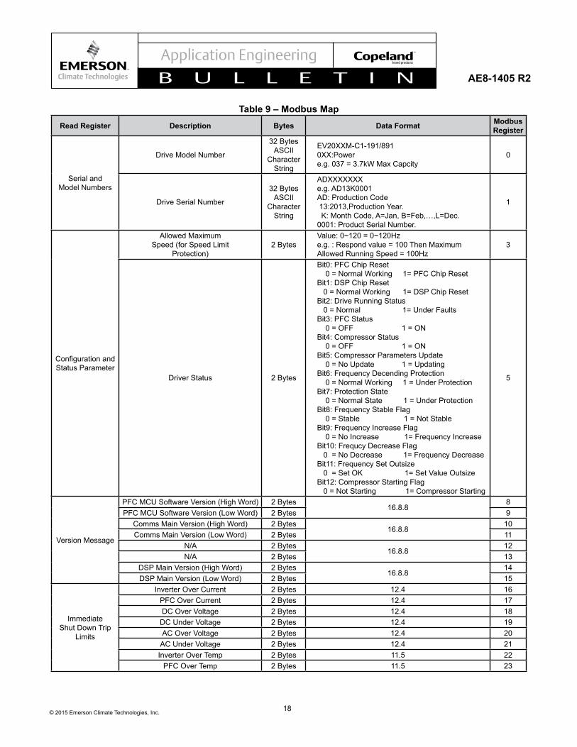
Table 9 – Modbus MapRead Register Description Bytes Data Format Modbus
Register
Serial and Model Numbers
Drive Model Number
32 Bytes ASCII
Character String
EV20XXM-C1-191/891 0XX:Power e.g. 037 = 3.7kW Max Capcity
0
Drive Serial Number
32 Bytes ASCII
Character String
ADXXXXXXX e.g. AD13K0001 AD: Production Code 13:2013,Production Year. K: Month Code, A=Jan, B=Feb,…,L=Dec. 0001: Product Serial Number.
1
ConfigurationandStatus Parameter
Allowed Maximum Speed (for Speed Limit
Protection)2 Bytes
Value: 0~120 = 0~120Hz e.g. : Respond value = 100 Then Maximum Allowed Running Speed = 100Hz
3
Driver Status 2 Bytes
Bit0: PFC Chip Reset 0 = Normal Working 1= PFC Chip Reset Bit1: DSP Chip Reset 0 = Normal Working 1= DSP Chip Reset Bit2: Drive Running Status 0 = Normal 1= Under Faults Bit3: PFC Status 0 = OFF 1 = ON Bit4: Compressor Status 0 = OFF 1 = ON Bit5: Compressor Parameters Update 0 = No Update 1 = Updating Bit6: Frequency Decending Protection 0 = Normal Working 1 = Under Protection Bit7: Protection State 0 = Normal State 1 = Under Protection Bit8: Frequency Stable Flag 0 = Stable 1 = Not Stable Bit9: Frequency Increase Flag 0 = No Increase 1= Frequency Increase Bit10: Frequcy Decrease Flag 0 = No Decrease 1= Frequency Decrease Bit11: Frequency Set Outsize 0 = Set OK 1= Set Value Outsize Bit12: Compressor Starting Flag 0 = Not Starting 1= Compressor Starting
5
Version Message
PFC MCU Software Version (High Word) 2 Bytes16.8.8
8PFC MCU Software Version (Low Word) 2 Bytes 9
Comms Main Version (High Word) 2 Bytes16.8.8
10Comms Main Version (Low Word) 2 Bytes 11
N/A 2 Bytes16.8.8
12N/A 2 Bytes 13
DSP Main Version (High Word) 2 Bytes16.8.8
14DSP Main Version (Low Word) 2 Bytes 15
Immediate Shut Down Trip
Limits
Inverter Over Current 2 Bytes 12.4 16PFC Over Current 2 Bytes 12.4 17DC Over Voltage 2 Bytes 12.4 18
DC Under Voltage 2 Bytes 12.4 19AC Over Voltage 2 Bytes 12.4 20AC Under Voltage 2 Bytes 12.4 21Inverter Over Temp 2 Bytes 11.5 22
PFC Over Temp 2 Bytes 11.5 23
19© 2015 Emerson Climate Technologies, Inc.
AE8-1405 R2
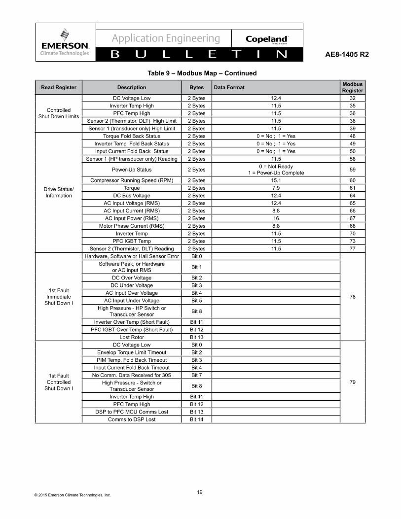
Read Register Description Bytes Data Format Modbus Register
Controlled Shut Down Limits
DC Voltage Low 2 Bytes 12.4 32Inverter Temp High 2 Bytes 11.5 35
PFC Temp High 2 Bytes 11.5 36Sensor 2 (Thermistor, DLT) High Limit 2 Bytes 11.5 38Sensor 1 (transducer only) High Limit 2 Bytes 11.5 39
Drive Status/Information
Torque Fold Back Status 2 Bytes 0 = No ; 1 = Yes 48Inverter Temp Fold Back Status 2 Bytes 0 = No ; 1 = Yes 49Input Current Fold Back Status 2 Bytes 0 = No ; 1 = Yes 50
Sensor 1 (HP transducer only) Reading 2 Bytes 11.5 58
Power-Up Status 2 Bytes 0 = Not Ready 1 = Power-Up Complete 59
Compressor Running Speed (RPM) 2 Bytes 15.1 60Torque 2 Bytes 7.9 61
DC Bus Voltage 2 Bytes 12.4 64AC Input Voltage (RMS) 2 Bytes 12.4 65AC Input Current (RMS) 2 Bytes 8.8 66AC Input Power (RMS) 2 Bytes 16 67
Motor Phase Current (RMS) 2 Bytes 8.8 68Inverter Temp 2 Bytes 11.5 70
PFC IGBT Temp 2 Bytes 11.5 73Sensor 2 (Thermistor, DLT) Reading 2 Bytes 11.5 77
1st Fault Immediate
Shut Down I
Hardware, Software or Hall Sensor Error Bit 0
78
Software Peak, or Hardware or AC input RMS Bit 1
DC Over Voltage Bit 2DC Under Voltage Bit 3
AC Input Over Voltage Bit 4AC Input Under Voltage Bit 5
High Pressure - HP Switch or Transducer Sensor Bit 8
Inverter Over Temp (Short Fault) Bit 11PFC IGBT Over Temp (Short Fault) Bit 12
Lost Rotor Bit 13
1st Fault Controlled
Shut Down I
DC Voltage Low Bit 0
79
Envelop Torque Limit Timeout Bit 2PIM Temp. Fold Back Timeout Bit 3
Input Current Fold Back Timeout Bit 4No Comm. Data Received for 30S Bit 7
High Pressure - Switch or Transducer Sensor Bit 8
Inverter Temp High Bit 11PFC Temp High Bit 12
DSP to PFC MCU Comms Lost Bit 13Comms to DSP Lost Bit 14
Table 9 – Modbus Map – Continued
20© 2015 Emerson Climate Technologies, Inc.
AE8-1405 R2
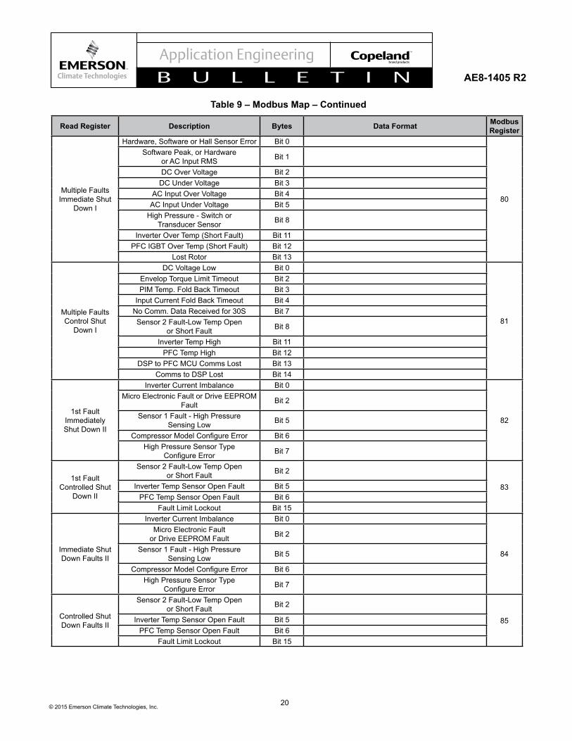
Read Register Description Bytes Data Format Modbus Register
Multiple Faults Immediate Shut
Down I
Hardware, Software or Hall Sensor Error Bit 0
80
Software Peak, or Hardware or AC Input RMS Bit 1
DC Over Voltage Bit 2DC Under Voltage Bit 3
AC Input Over Voltage Bit 4AC Input Under Voltage Bit 5
High Pressure - Switch or Transducer Sensor Bit 8
Inverter Over Temp (Short Fault) Bit 11PFC IGBT Over Temp (Short Fault) Bit 12
Lost Rotor Bit 13
Multiple Faults Control Shut
Down I
DC Voltage Low Bit 0
81
Envelop Torque Limit Timeout Bit 2PIM Temp. Fold Back Timeout Bit 3
Input Current Fold Back Timeout Bit 4No Comm. Data Received for 30S Bit 7Sensor 2 Fault-Low Temp Open
or Short Fault Bit 8
Inverter Temp High Bit 11PFC Temp High Bit 12
DSP to PFC MCU Comms Lost Bit 13Comms to DSP Lost Bit 14
1st Fault Immediately Shut Down II
Inverter Current Imbalance Bit 0
82
Micro Electronic Fault or Drive EEPROM Fault Bit 2
Sensor 1 Fault - High Pressure Sensing Low Bit 5
CompressorModelConfigureError Bit 6High Pressure Sensor Type
ConfigureError Bit 7
1st Fault Controlled Shut
Down II
Sensor 2 Fault-Low Temp Open or Short Fault Bit 2
83Inverter Temp Sensor Open Fault Bit 5PFC Temp Sensor Open Fault Bit 6
Fault Limit Lockout Bit 15
Immediate Shut Down Faults II
Inverter Current Imbalance Bit 0
84
Micro Electronic Fault or Drive EEPROM Fault Bit 2
Sensor 1 Fault - High Pressure Sensing Low Bit 5
CompressorModelConfigureError Bit 6High Pressure Sensor Type
ConfigureError Bit 7
Controlled Shut Down Faults II
Sensor 2 Fault-Low Temp Open or Short Fault Bit 2
85Inverter Temp Sensor Open Fault Bit 5PFC Temp Sensor Open Fault Bit 6
Fault Limit Lockout Bit 15
Table 9 – Modbus Map – Continued
21© 2015 Emerson Climate Technologies, Inc.
AE8-1405 R2
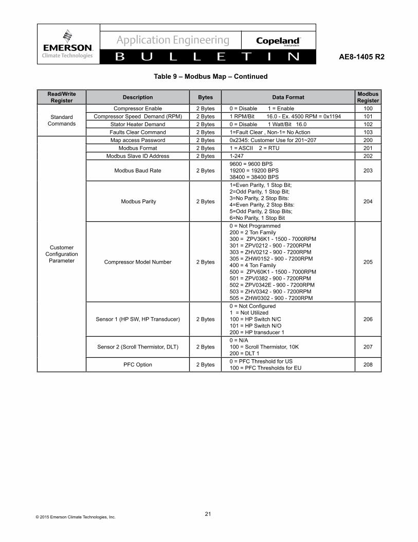
Read/Write Register Description Bytes Data Format Modbus
Register
Standard Commands
Compressor Enable 2 Bytes 0 = Disable 1 = Enable 100Compressor Speed Demand (RPM) 2 Bytes 1 RPM/Bit 16.0 - Ex. 4500 RPM = 0x1194 101
Stator Heater Demand 2 Bytes 0 = Disable 1 Watt/Bit 16.0 102Faults Clear Command 2 Bytes 1=Fault Clear , Non-1= No Action 103
Customer Configuration
Parameter
Map access Password 2 Bytes 0x2345: Customer Use for 201~207 200Modbus Format 2 Bytes 1 = ASCII 2 = RTU 201
Modbus Slave ID Address 2 Bytes 1-247 202
Modbus Baud Rate 2 Bytes9600 = 9600 BPS 19200 = 19200 BPS 38400 = 38400 BPS
203
Modbus Parity 2 Bytes
1=Even Parity, 1 Stop Bit; 2=Odd Parity, 1 Stop Bit; 3=No Parity, 2 Stop Bits: 4=Even Parity, 2 Stop Bits: 5=Odd Parity, 2 Stop Bits; 6=No Parity, 1 Stop Bit
204
Compressor Model Number 2 Bytes
0 = Not Programmed 200 = 2 Ton Family 300 = ZPV36K1 - 1500 - 7000RPM 301 = ZPV0212 - 900 - 7200RPM 303 = ZHV0212 - 900 - 7200RPM 305 = ZHW0152 - 900 - 7200RPM 400 = 4 Ton Family 500 = ZPV60K1 - 1500 - 7000RPM 501 = ZPV0382 - 900 - 7200RPM 502 = ZPV0342E - 900 - 7200RPM 503 = ZHV0342 - 900 - 7200RPM 505 = ZHW0302 - 900 - 7200RPM
205
Sensor 1 (HP SW, HP Transducer) 2 Bytes
0=NotConfigured 1 = Not Utilized 100 = HP Switch N/C 101 = HP Switch N/O 200 = HP transducer 1
206
Sensor 2 (Scroll Thermistor, DLT) 2 Bytes0 = N/A 100 = Scroll Thermistor, 10K 200 = DLT 1
207
PFC Option 2 Bytes 0 = PFC Threshold for US 100 = PFC Thresholds for EU 208
Table 9 – Modbus Map – Continued
22© 2015 Emerson Climate Technologies, Inc.
AE8-1405 R2
Table 10 - Input Current FoldbackCondition Action taken by the Drive
1 Input Current >= Foldback Current Will Reduce the Speed to Minimum Speed at Rate of 20 rpm Per Second
2 Recovering Current <= Input Current < Foldback Current Will Remain in the Current Speed
3 Input Current < Recovering Current Speed Will Be Recovered to Commanded Speed4 Drive in Foldback State for >=30 sec Compressor Will Be Tripped
Table 11 - Output Current FoldbackCondition Action taken by the Drive
1 Output Current >= Foldback Limit of Operating Speed Range
Will Reduce to Minimum Speed of the Speed Range at Rate of 20 rpm Per Second
2Recovering Current <= Output Current < Foldback Limit of Operating Speed
RangeWill Remain in the Current Speed
3 Output Current < Recovering Current Speed Will Be Recovered to Commanded Speed4 Drive in Foldback State for >=30 sec Compressor Will Be Tripped
Table 12 - Inverter Temperature FoldbackCondition Action taken by the Drive
1 Inverter Temperature >= Foldback Temperature Will Reduce the Speed to Minimum Speed at Rate of 20 rpm Per Second
2 Recovering Temperature <= Inverter Temperature < Foldback Temperature Will Remain in the Current Speed
3 Inverter Temperature < Recovering Temperature Speed Will Be Recovered to Commanded Speed
4 Drive in Foldback State for >=30 sec Compressor Will Be Tripped
The contents of this publication are presented for informational purposes only and they are not to be construed as warranties or guarantees, express or implied, regarding the products or servicesdescribedhereinortheiruseorapplicability.EmersonClimateTechnologies,Inc.reservestherighttomodifythedesignsorspecificationsofsuchproductsatanytimewithoutnotice. Emerson Climate Technologies, Inc. does not assume responsibility for the selection, use or maintenance of any product. Responsibility for proper selection, use and maintenance of any Emerson Climate Technologies, Inc. product remains solely with the purchaser and end-user.