Embed Size (px)
Citation preview
1© 2016 Emerson Climate Technologies, Inc.
AE8-1384 R5
AE8-1384 R5
CoreSense™ Communications for 20 to 40 Ton Copeland Scroll™ Air Conditioning Compressors
August 2016
Safety Safety Instructions ...................................................2 Safety Icon Explanation ...........................................2 Instructions Pertaining to Risk of Electrical Shock, Fire, or Injury to Persons .............................3 Safety Statements ...................................................3
Introduction Overview ..................................................................4 Features ..................................................................4 Application Usage ....................................................4 Part Numbers ..........................................................4 Agency Recognition .................................................4 ProductSpecifications .............................................4
Installation Mounting ..................................................................4 Terminal Description and Basic Field Wiring ...........4 Dielectric (Hipot) Testing ..........................................5
Operation Warning Codes ........................................................5 Alert/Lockout Codes ...................................................5 Resetting Alert Codes ..............................................6
TABLE OF CONTENTS
Section Page Section Page
Commissioning Communications ......................................................6 DIPSwitchConfiguration .........................................7 Jumper Setting ........................................................7 PC Interface Software .............................................7
Service Field Service ............................................................8 Troubleshooting .......................................................8
Tables Module Part Numbers ..............................................9 ModuleSpecifications ..............................................9 Accessory Parts .......................................................9 Modbus Map .....................................................10-12 DIP Switch Purpose ...............................................13 LED Flash Code Information ............................13-14
Figures Terminal Box Wiring Diagrams ..............................15 CoreSense Communications Module Photo ..........16 Thermistor Circuit Cable ........................................16 Modbus Addressing ...............................................17 PC Interface Wiring ...............................................18
2© 2016 Emerson Climate Technologies, Inc.
AE8-1384 R5
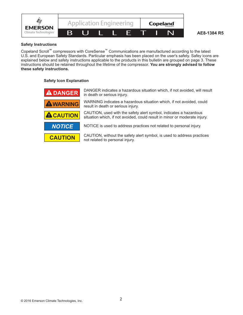
Safety Instructions
Copeland Scroll™ compressors with CoreSense™ Communications are manufactured according to the latest U.S. and European Safety Standards. Particular emphasis has been placed on the user's safety. Safey icons are explained below and safety instructions applicable to the products in this bulletin are grouped on page 3. These instructions should be retained throughout the lifetime of the compressor. You are strongly advised to follow these safety instructions.
Safety Instructions Copeland Scroll™ compressors are manufactured according to the latest U.S. and European Safety Standards. Particular emphasis has been placed on the user's safety. Safey icons are explained below and safety instructions applicable to the products in this bulletin are grouped on Page 3. These instructions should be retained throughout the lifetime of the compessor. You are strongly advised to follow these safety instructions.
Safety Icon Explanation
DANGER indicates a hazardous situation which, if not avoided, will result in death or serious injury.
WARNING indicates a hazardous situation which, if not avoided, could result in death or serious injury.
CAUTION, used with the safety alert symbol, indicates a hazardous situation which, if not avoided, could result in minor or moderate injury.
NOTICE is used to address practices not related to personal injury.
CAUTION, without the safety alert symbol, is used to address practices not related to personal injury.
DANGER
WARNING
CAUTION
NOTICE
CAUTION
3© 2016 Emerson Climate Technologies, Inc.
AE8-1384 R5
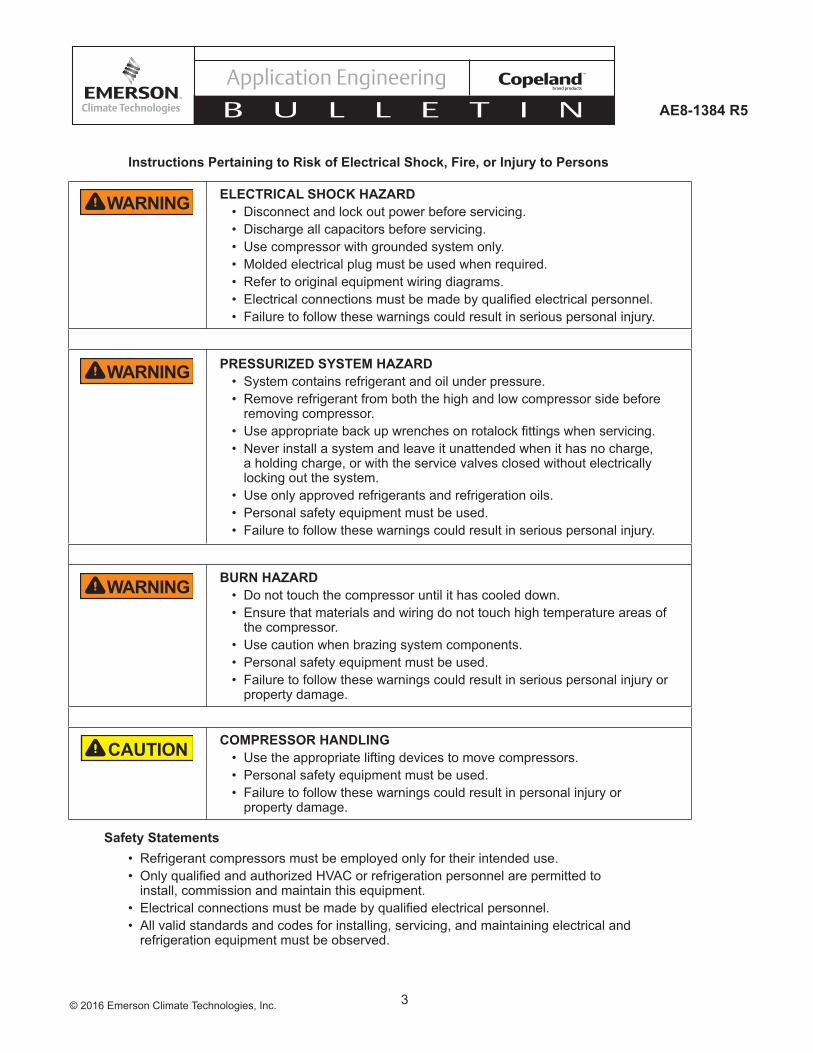
ELECTRICAL SHOCK HAZARD• Disconnect and lock out power before servicing. • Discharge all capacitors before servicing. • Use compressor with grounded system only. • Molded electrical plug must be used when required. • Refer to original equipment wiring diagrams. • • Failure to follow these warnings could result in serious personal injury.
PRESSURIZED SYSTEM HAZARD• System contains refrigerant and oil under pressure.• Remove refrigerant from both the high and low compressor side before
removing compressor. • • Never install a system and leave it unattended when it has no charge,
a holding charge, or with the service valves closed without electrically locking out the system.
• Use only approved refrigerants and refrigeration oils. • Personal safety equipment must be used. • Failure to follow these warnings could result in serious personal injury.
BURN HAZARD• Do not touch the compressor until it has cooled down. • Ensure that materials and wiring do not touch high temperature areas of
the compressor. • Use caution when brazing system components. • Personal safety equipment must be used. • Failure to follow these warnings could result in serious personal injury or
property damage.
COMPRESSOR HANDLING• Use the appropriate lifting devices to move compressors. • Personal safety equipment must be used. • Failure to follow these warnings could result in personal injury or
property damage.
Safety Statements• Refrigerant compressors must be employed only for their intended use. •
install, commission and maintain this equipment. • • All valid standards and codes for installing, servicing, and maintaining electrical and
refrigeration equipment must be observed.
Instructions Pertaining to Risk of Electrical Shock, Fire, or Injury to Persons
WARNING
WARNING
WARNING
CAUTION
4© 2016 Emerson Climate Technologies, Inc.
AE8-1384 R5
INTRODUCTION OverviewCoreSense™ Communications is a breakthrough innovation for 20 to 40 ton Copeland Scroll™
air conditioning compressors. The CoreSense Communications module, installed in the compressor electrical box, provides advanced diagnostics, protection, and communications that enhance compressor performance and reliability.
FeaturesCoreSense Communications has the following key features:
1. Motor temperature protection2. Scroll high temperature protection3. Missing phase protection4. Reverse phase protection5. Low control circuit voltage protection6. Short cycling detection and alert7. Communication to system controller through
RS485/Modbus8. Storage of operational history, runtime information,
fault counters, etc.9. Display of status, warning, and alert information
via LEDs
CoreSense Communications provides compressor and system protection through its proprietary lockout feature. Depending on the severity and frequency of the fault that caused the trip condition, the CoreSense Communications module can lockout the compressor contactor to prevent damage to the compressor and system components. Less severe fault conditions resulting in an occasional trip will not result in a lockout condition.
Flashing red and green LEDs communicate Status, Warning, and Alert codes to the service technician and the master controller.
Application Usage
WARNINGCoreSense Communications modules are not interchangeable with any other brand of motor protection module that may have been previously used with Copeland Scroll compressors.
CoreSense Communications modules are not intended tobeusedasfieldretrofitsforothermotorprotection
modules that may have been previously used with Copeland Scroll compressors. The motor and scroll thermistor circuits are configured differently for Copeland Scroll with CoreSense Communications and are not compatible with motor protection modules that were previously used.
Copeland Scroll compressors equipped with CoreSense Communications will have an “E” in the electrical code. An example is the 40-ton scroll, ZP485KCE-TED.
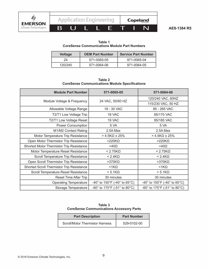
Module Part NumbersOEM and service compressors will have the CoreSense Communications module installed in the compressor electrical box. Individually packaged modules are available to the aftermarket for component replacement. Part numbers for OEM and service applications are listed in Table 1 at the end of this bulletin.
Agency RecognitionCoreSense Communications carries the following agency recognitions:U.L.fileE253322,Volume7,SoftwareClassBCBTestCertificate
Product SpecificationsCoreSensespecificationsareshowninTable 2. Many of the electrical specifcations are the same as previously used electronic motor protection modules.
INSTALLATIONMountingAs mentioned above, CoreSense Communications will be shipped already installed in the compressor electrical box. Two holding tabs secure the module in the box. To remove the module depress the holding tabs and remove the module.
WARNINGAlways disconnect and lockout the power supply before removing the compressor electrical box cover for servicing.
Terminal Description and Basic Field WiringFigure 2 at the end of this bulletin shows the CoreSense Communications module. Figures 1a and 1b are the terminal box wiring diagrams. An explanation of the terminal designations follows:
T2-T1:Modulepowersupply,24or120/240VAC.L1-L2-L3: Phase inputs corresponding to compressor input power L1-L2-L3.
5© 2016 Emerson Climate Technologies, Inc.
AE8-1384 R5
M2-M1: Normally open control circuit contacts; M2-M1 should be wired in series with the compressor contactor.
A (-), GND, B (+): RS485 communications.
Temperature Plug: See Figure 3foridentificationofthe PTC, NTC, and common connections.
When multiple CoreSense Communications modules are networked, a shielded, twisted pair cable such as Beldon #8761 (22 AWG) should be used for the communication wiring.
NOTICEThe RS485 is polarity sensitive. When “daisy chaining” modules the A (-) must connect to other A (-) terminals and B (+) must connect to other B (+) terminals.
Dielectric (Hipot) Testing
CAUTIONUse caution with high voltage and never hipot when compressor is in a vacuum.
U.L. sets the requirement for dielectric strength testing and should be consulted for the appropriate voltage and leakage values. Emerson Climate Technologies does not recommend hipot testing at voltages higher than1,000VAC.
OPERATION
WARNINGThe CoreSense Communications module is a recognized safety device and must be used with all compressors that have TE* electrical codes.
A solid green LED indicates the module is powered and operation is normal. A solid red LED indicates an internal problem with the module. See the Troubleshooting section of this bulletin for more information on what to do if the red LED is solid.
CoreSense Communications communicates Warning codesviaagreenflashingLED.Warningcodesdonotresult in a trip or lockout condition. Alert codes are communicated via a red flashing LED.Alert codes will result in a trip condition and possibly a lockout condition.
Warning Codes (Green LED Flash Code)Code 1 – Loss of CommunicationThemodulewillflashthegreenWarning LED one time indicating the module has not communicated with the master controller for longer than 5 minutes. Once communication is reinitiated, the Warning will be cleared.
Code 2 – Reserved For Future Use
Code 3 – Short CyclingThemodulewillflashthegreenWarning LED three times indicating the compressor has short cycled more than48timesin24hours.Ashortcycleisdefinedascompressor runtime of less than 3 minutes. The Warning will be activated when the “Short Cycling” dipswitch (#10) is "off" or in the "down" position. When fewer than 48 short cycles are accumulated in 24 hours the Warning code will be cleared.
Code 4 – Open/Shorted Scroll ThermistorThemodulewillflashthegreenWarning LED four times indicating the scroll NTC thermistor has a resistance value that indicates an open/shorted thermistor (see Table 2). The Warning will be cleared when the resistance value is in the normal range.
Alert/Lockout Codes (Red LED Flash Code)Code 1 – Motor High TemperatureThemodulewill flash the redAlert LED one time indicating the motor PTC circuit has exceeded 4.5K Ohms ± 25%. A code 1 Alert will open the M2-M1 contacts. The Alert will reset after 30 minutes and the M2-M1 contacts will close if the resistance of the motor PTC circuit is below 2.75K Ohms. Five consecutive Code 1 Alerts will lockout the compressor. Once the module has locked out the compressor, a power cycle or Modbus reset command will be required for the lockout to be cleared.
Code 2 – Open/Shorted Motor ThermistorThemodulewillflash theredAlert LED two times indicating the motor PTC thermistor circuit has a resistance value that indicates an open/shorted thermistor chain (see Table 2). A Code 2 Alert will open the M2-M1 contacts. The Alert will reset after 30 minutes and the M2-M1 contacts will close if the resistance of the motor PTC circuit is back in the normal range. The module will lockout the compressor if the trip condition exists for longer than 6 hours.
6© 2016 Emerson Climate Technologies, Inc.
AE8-1384 R5
Once the module has locked out the compressor, a power cycle or Modbus reset command will be required to clear the lockout.
Code 3 – Short CyclingThemodulewillflashtheredAlert LED three times indicating the compressor is locked out due to short cycling. A Code 3 Alert will open the M2-M1 contacts. Code 3 will be enabled when the "Short Cycling" dipswitch (#10) is "on" or in the "up" position and the compressor has exceeded the number of short cycles configuredbytheuserina24hourperiod.Oncethemodule has locked out the compressor, a power cycle or Modbus reset command will be required to clear the lockout.
Code 4 – Scroll High TemperatureThemodulewillflashtheredAlert LED four times indicating the scroll NTC circuit is less than 2.4K Ohms. A Code 4 Alert will open the M2-M1 contacts. The Alert will reset after 30 minutes and the M2-M1 contacts will close if the resistance of the scroll NTC circuit is higher than 5.1K Ohms. The module will lockout the compressor if the number of Code 4 Alerts exceeds theuserconfigurablenumberofCode 4 events within a 24 hour period. Once the module has locked out the compressor, a power cycle or Modbus reset command will be required to clear the lockout.
Code 5 – Reserved for Future Use
Code 6 – Missing Phase Themodulewill flash the redAlert LED six times indicating a missing phase in one of the three leads to the compressor. A Code 6 Alert will open the M2-M1 contacts. The Alert will reset after 5 minutes and the M2-M1 contacts will close if the missing phase condition is not present. The module will lockout the compressor after 10 consecutive Code 6 Alerts. Once the module has locked out the compressor, a power cycle or Modbus reset command will be required to clear the lockout.
Code 7 – Reverse PhaseThemodulewillflashtheredAlert LED seven times indicating a reverse phase in two of the three leads to the compressor. A Code 7 Alert will open the M2-M1 contacts. The module will lockout the compressor after one Code 7 Alert. A power cycle or Modbus reset command will be required to clear the lockout.
Code 8 – Reserved For Future Use
Code9–ModuleLowVoltageThemodulewillflashtheredAlert LED nine times indicating low module voltage (see Table 2) on the T2-T1 terminals for more than 5 seconds. A Code 9 Alert will open the M2-M1 contacts. The Alert will reset after 5 minutes and the M2-M1 contacts will close if the T2-T1 voltage is above the reset value in Table 2.
Please see Table 6 for a summary of Warning and Alert codes and troubleshooting information.
Resetting Alert CodesResetting Alert codes can be accomplished in two different ways. First, Alert codes can be reset manually by cycling power to the module (disconnect T2 or T1 for 5 seconds). The second way to reset Alert codes is to send a Modbus reset command from the master controller.
Power Up DelayWhen CoreSense Communications is cycled off, there isathirteentofifteenseconddelaybeforethemoduleis active.
If the fault that initiated the Alert code is absent after one of the above resets is performed, the Alert code will be cleared and CoreSense will allow normal operation. If the fault is still present after the reset is performed the fault code will continue to be displayed via the green orredflashingLED.
COMMISSIONINGCommunicationsProgramming knowledge and a familiarity with Modbus will be required by the system designer to use the communications features of CoreSense Communications. CoreSense Communications has opto-isolated RS485 for the physical layer. The communication protocol is Standard Modbus and Emerson Climate Technologies Modbus. CoreSense Communications will act as the Modbus slave, while the master will be implemented in a system controller, PC software, or any other equivalent external device. Use of the communications feature of CoreSense Communications allows the master access to much of the data that resides in the CoreSense Communications module. Emerson Climate Technologies Modbus has six message categories:
1. Device ID Messages2. CoreSense Status Messages
7© 2016 Emerson Climate Technologies, Inc.
AE8-1384 R5
3. CoreSense History Status Messages4. ConfigurationMessages5. Command Messages6. Firmware Update Messages
CoreSense status, configuration, history, and deviceinformation messages available to the master include those listed in Table 4.
The history status messages give the order in which the Warning/Alert has happened, with the total compressor run time. Information about the Warning/Alert occurrence during the last 7 days and the cumulative Warning/Alert counter are also available.
For more information on CoreSense™ Communications features and to request Modbus maps please contact your Application Engineer.
DIP Switch ConfigurationDIP switch selection for the Modbus address, baud rate, parity, and other operating conditions simplify service and start-up procedures. Table 5 lists the purpose of each switch.
NOTICEThe module must be reset after changing any of the DIP switch settings for changes to take effect.
CoreSense Communications modules are shipped from the factory with the DIP switches set to default settings for standalone operation. Default settings are shown in Table 5. Switch 1 is turned “on” as part of a quality control check to verify communications capability of the module before it leaves the compressor manufacturing plant. Switch 9 is also turned “on” for TE* motor code. All other DIP switch default settings are in the “off” position.
NOTICEIf DIP switch settings are inadvertently changed, the compressor will operate, but could have some loss of protection. Scroll temperature protection and short cycle protection could be disabled.
The following steps cover the DIP switch settings throughout the commissioning process for a multiple compressor system with communications.
1. Switches 1 through 5 are used for setting the device address. DIP switch 1 is the least significant bit (LSB) and switch 5 is the mostsignificant bit (MSB). DIP switch addresses0 through 31 are shown in Figure 4. Each
CoreSense Communications module that is daisy chained and connected to a master controller must have a unique node address (as determined by the DIP switch settings).
2. Switch6definesthecommunicationbaudrateforthe CoreSense Communications module. If the switch is “off”, the baud rate is 19200. If the switch is “on” the baud rate is 9600. The baud rate of each CoreSense Communications module should be set to match the master controller baud rate.
3. Switch 7 defines the communications parity.The default parity setting for the CoreSense Communications module is no parity. If the switch is set to “on” the module will communicate using even parity. The parity setting must match the parity setting of the master controller.
4. Switch 8 defines the control mode. The default setting is standalone mode (off). If communications with a master controller is desired, switch 8 should be turned “on” to network.
5. Switch9definesthethermistorconfiguration.Ifthe compressor has a voltage code of TE*, the compressor has PTC and NTC thermistors for motor and scroll temperature protection. If the compressor voltage code is TW*, the compressor has only PTC thermistors for motor and scroll temperature protection. The default setting is “on” for PTC and NTC thermistor types.
6. Switch 10 enables short cycling protection if turned “on”. The default setting is “off”.
Jumper SettingCoreSense Communications modules are shipped with the jumper installed. For standalone operation the jumper should remain installed. For daisy chained applications the jumper should remain installed for the modules on the ends of the daisy chain. All other jumpers in the sequence of daisy chained modules should be removed. The jumper can be removed using miniature electronics needle nose pliers
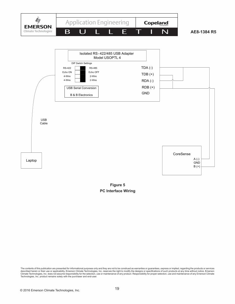
PC Interface SoftwarePC interface software is available from Emerson Climate Technologies, Inc. The PC interface software allows the design engineer access to status, configuration,history, and data logging via a computer. This method of connecting and communicating with CoreSense is very helpful during the unit development stage if CoreSense is in stand-alone mode and not communicating with a master controller.
8© 2016 Emerson Climate Technologies, Inc.
AE8-1384 R5
The RS-485/USB adapter used to connect the laptop to the CoreSense is B & B Electronics model number USOPTL4. Figure 5 illustrates the wiring and DIP switch settings necessary to enable communications.
For more information on the PC interface software, how to obtain it, and a tutorial on its use, please contact your Application Engineer.
SERVICE
Field ServiceService compressors will be shipped with the CoreSense Communications module installed in the compressor terminal box. Special attention should be given to the module DIP switch settings of the compressor being replaced so the DIP switch settings can be transferred to the module of the replacement compressor. As mentioned earlier, the CoreSense Communications module is a recognized safety device and shall be used only with approved compressors with TE* motor codes.
NOTICEIf a compressor with CoreSense Communications fails in the field, the CoreSense module should remain with the failed compressor so Emerson technicians can download the CoreSense data to assist with determining the root cause of compressor failure.
Troubleshooting
WARNINGAlways disconnect and lockout the power supply before removing the compressor electrical box cover for servicing.
For troubleshooting purposes the scroll and motor thermistor circuits are similar to those of other Copeland Scrolls with one exception, the scroll thermistor is a
negativetemperaturecoefficient(NTC)typethermistor.This means that as the discharge temperature increases, the resistance of the thermistor decreases. The motor has positive temperature coefficient (PTC) type thermistors; as the motor temperature increases, so does the resistance of the thermistor chain. To measure the resistance of the PTC and NTC circuits simply remove the temperature plug from the CoreSense module and measure the resistance in the appropriate pins shown in Figure 3. The measured values should be in the ranges listed in Table 2. For information on trouble shooting causes of high motor and scroll temperatures please refer to the application engineering bulletin for the compressor.
A loss of communications with the master controller for morethanfiveminutes iscommunicatedviaagreenflashcode1 ifDIPswitch#8 isenabled.CoreSenseCommunications has no provisions to detect incorrect wiring neither between daisy chained modules nor to the master controller. Ideally, the master controller will contain advanced troubleshooting menus for help in diagnosing communications issues between the master controller and the CoreSense module.
NOTICE
In some rare cases communication between the master controller and the CoreSense module is problematic. Reversing the polarity will re-initiate communication.
To reverse polarity:
1. Adjust CoreSense to negative 2. Adjust master controller to positive
9© 2016 Emerson Climate Technologies, Inc.
AE8-1384 R5
Voltage OEM Part Number Service Part Number24 571-0065-05 971-0065-04
120/240 571-0064-06 971-0064-05
Table 1 CoreSense Communications Module Part Numbers
Part Description Part Number
Scroll/Motor Thermistor Harness 529-0102-00
Table 3 CoreSense Communications Accessory Parts
Table 2 CoreSense Communications Module Specifications
Module Part Number 571-0065-05 571-0064-06
ModuleVoltage&Frequency 24VAC,50/60HZ120/240VAC,60HZ115/230VAC,50HZ
AllowableVoltageRange 18-30VAC 85-265VAC
T2/T1LowVoltageTrip 18VAC 85/170VAC
T2/T1LowVoltageReset 19VAC 95/185VACPower Consumption 5VA 5VA
M1/M2 Contact Rating 2.5A Max 2.5A MaxMotor Temperature Trip Resistance >4.5KΩ±25% >4.5KΩ±25%
Open Motor Thermistor Trip Resistance >220KΩ >220KΩShorted Motor Thermistor Trip Resistance <40Ω <40Ω
Motor Temperature Reset Resistance <2.75KΩ <2.75KΩScroll Temperature Trip Resistance <2.4KΩ <2.4KΩ
Open Scroll Thermistor Trip Resistance >370KΩ >370KΩShorted Scroll Thermistor Trip Resistance <1KΩ <1KΩ
Scroll Temperature Reset Resistance >5.1KΩ >5.1KΩReset Time After Trip 30 minutes 30 minutes
Operating Temperature -40° to 150°F (-40° to 65°C) -40° to 150°F (-40° to 65°C)Storage Temperature -60° to 175°F (-51° to 80°C) -60° to 175°F (-51° to 80°C)
10© 2016 Emerson Climate Technologies, Inc.
AE8-1384 R5
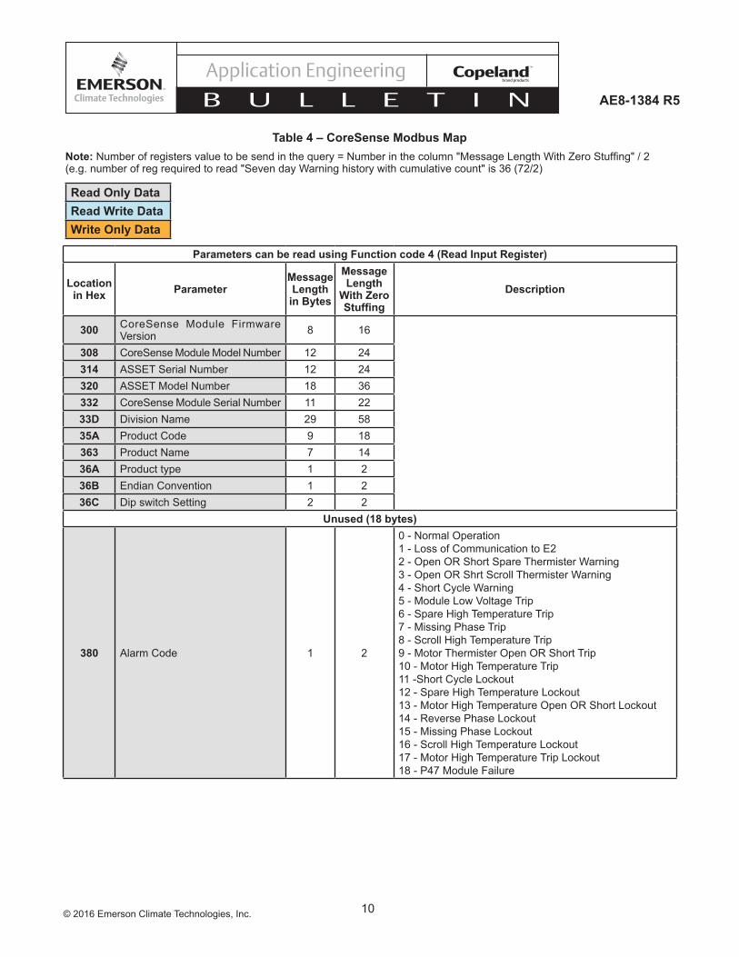
Table 4 – CoreSense Modbus Map
Parameters can be read using Function code 4 (Read Input Register)
Location in Hex Parameter
Message Length
in Bytes
Message Length
With Zero Stuffing
Description
300 CoreSense Module Firmware Version 8 16
308 CoreSense Module Model Number 12 24314 ASSET Serial Number 12 24320 ASSET Model Number 18 36332 CoreSense Module Serial Number 11 2233D Division Name 29 5835A Product Code 9 18363 Product Name 7 1436A Product type 1 236B Endian Convention 1 236C Dip switch Setting 2 2
Unused (18 bytes)
380 Alarm Code 1 2
0 - Normal Operation1 - Loss of Communication to E22 - Open OR Short Spare Thermister Warning3 - Open OR Shrt Scroll Thermister Warning4 - Short Cycle Warning5-ModuleLowVoltageTrip6 - Spare High Temperature Trip7 - Missing Phase Trip8 - Scroll High Temperature Trip9 - Motor Thermister Open OR Short Trip10 - Motor High Temperature Trip11 -Short Cycle Lockout12 - Spare High Temperature Lockout13 - Motor High Temperature Open OR Short Lockout14 - Reverse Phase Lockout15 - Missing Phase Lockout16 - Scroll High Temperature Lockout17 - Motor High Temperature Trip Lockout18 - P47 Module Failure
Note: Numberofregistersvaluetobesendinthequery=Numberinthecolumn"MessageLengthWithZeroStuffing"/2(e.g. number of reg required to read "Seven day Warning history with cumulative count" is 36 (72/2)
Read Only DataRead Write DataWrite Only Data
11© 2016 Emerson Climate Technologies, Inc.
AE8-1384 R5
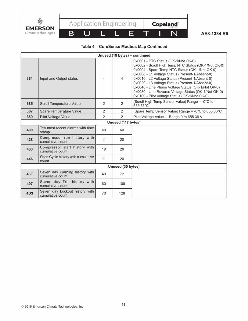
Unused (18 bytes) – continued
381 Input and Output status 4 4
0x0001 - PTC Status (OK-1/Not OK-0)0x0002 - Scroll High Temp NTC Status (OK-1/Not OK-0)0x0004 - Spare Temp NTC Status (OK-1/Not OK-0)0x0008-L1VoltageStatus(Present-1/Absent-0)0x0010-L2VoltageStatus(Present-1/Absent-0)0x0020-L3VoltageStatus(Present-1/Absent-0)0x0040-LinePhaseVoltageStatus(OK-1/NotOK-0)0x0080-LineReverseVoltageStatus(OK-1/NotOK-0)0x0100-PilotVoltageStatus(OK-1/NotOK-0)
385 ScrollTemperatureValue 2 2 (ScrollHighTempSensorValue)Range=-0°Cto655.36°C
387 SpareTemperatureValue 2 2 (SpareTempSensorValue)Range=-0°Cto655.36°C389 PilotVoltageValue 2 2 PilotVoltageValue–Range0to655.36V
Unused (117 bytes)
400 Ten most recent alarms with time stamp 40 60
428 Compressor run history with cumulative count 11 20
433 Compressor start history with cumulative count 19 20
446 Short Cycle history with cumulative count 11 20
Unused (30 bytes)
46F Seven day Warning history with cumulative count 40 72
497 Seven day Trip history with cumulative count 60 108
4D3 Seven day Lockout history with cumulative count 70 126
Table 4 – CoreSense Modbus Map Continued
12© 2016 Emerson Climate Technologies, Inc.
AE8-1384 R5
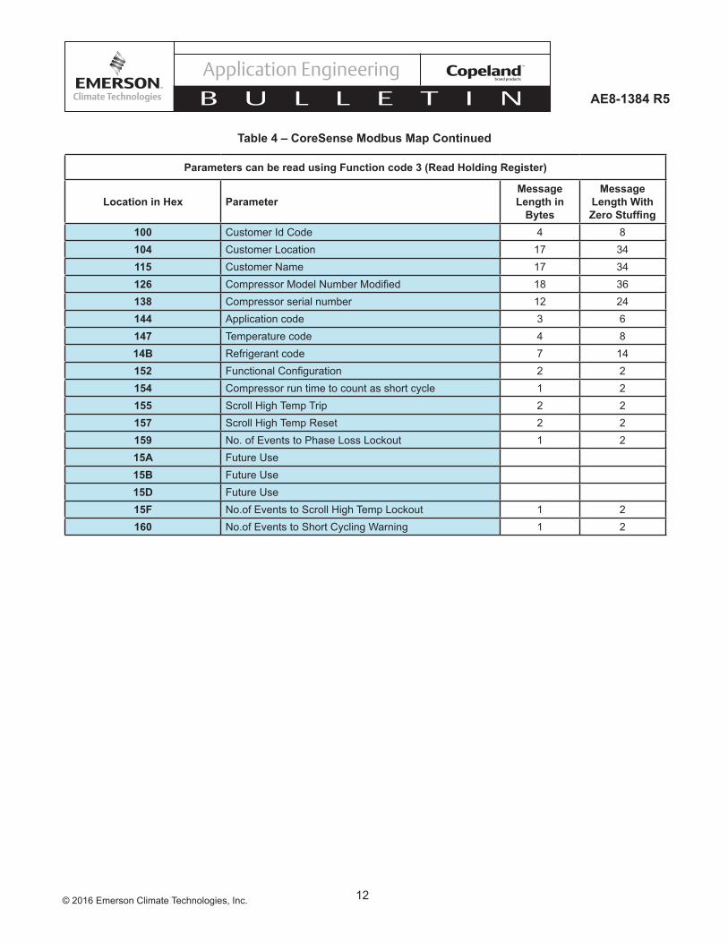
Parameters can be read using Function code 3 (Read Holding Register)
Location in Hex ParameterMessage Length in
Bytes
Message Length With Zero Stuffing
100 Customer Id Code 4 8104 Customer Location 17 34115 Customer Name 17 34126 CompressorModelNumberModified 18 36138 Compressor serial number 12 24144 Application code 3 6147 Temperature code 4 814B Refrigerant code 7 14152 FunctionalConfiguration 2 2154 Compressor run time to count as short cycle 1 2155 Scroll High Temp Trip 2 2157 Scroll High Temp Reset 2 2159 No. of Events to Phase Loss Lockout 1 215A Future Use15B Future Use15D Future Use15F No.of Events to Scroll High Temp Lockout 1 2160 No.of Events to Short Cycling Warning 1 2
Table 4 – CoreSense Modbus Map Continued
13© 2016 Emerson Climate Technologies, Inc.
AE8-1384 R5
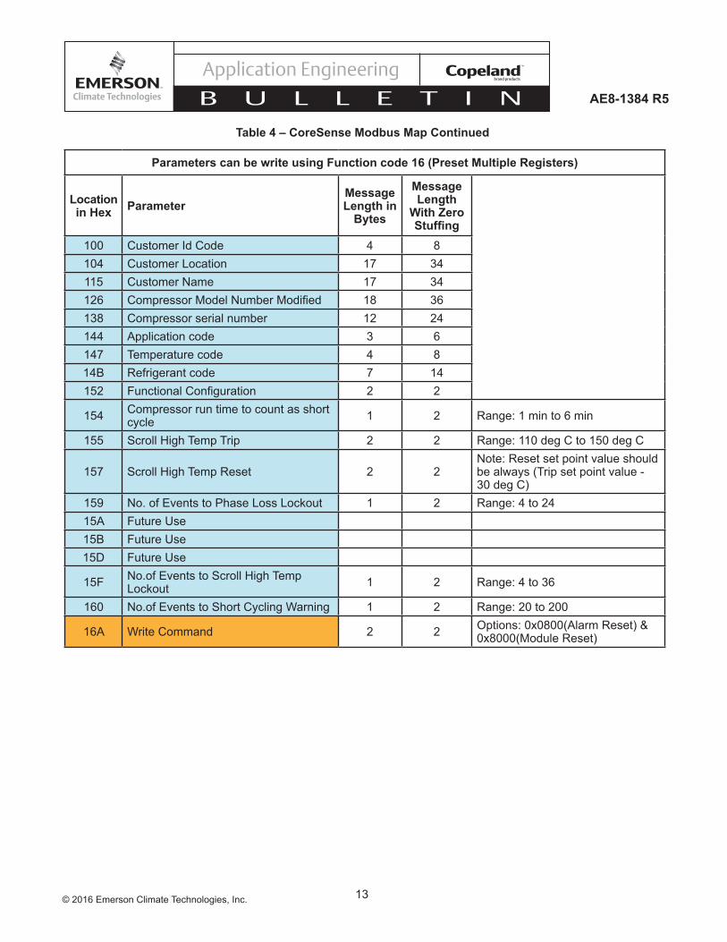
Parameters can be write using Function code 16 (Preset Multiple Registers)
Location in Hex Parameter
Message Length in
Bytes
Message Length
With Zero Stuffing
100 Customer Id Code 4 8104 Customer Location 17 34115 Customer Name 17 34126 CompressorModelNumberModified 18 36138 Compressor serial number 12 24144 Application code 3 6147 Temperature code 4 814B Refrigerant code 7 14152 FunctionalConfiguration 2 2
154 Compressor run time to count as short cycle 1 2 Range: 1 min to 6 min
155 Scroll High Temp Trip 2 2 Range: 110 deg C to 150 deg C
157 Scroll High Temp Reset 2 2Note: Reset set point value should be always (Trip set point value - 30 deg C)
159 No. of Events to Phase Loss Lockout 1 2 Range: 4 to 2415A Future Use15B Future Use15D Future Use
15F No.of Events to Scroll High Temp Lockout 1 2 Range: 4 to 36
160 No.of Events to Short Cycling Warning 1 2 Range: 20 to 200
16A Write Command 2 2 Options: 0x0800(Alarm Reset) & 0x8000(Module Reset)
Table 4 – CoreSense Modbus Map Continued
14© 2016 Emerson Climate Technologies, Inc.
AE8-1384 R5
Table 6 – CoreSense™ Communications LED Flash Code InformationTheflashcodenumbercorrespondstothenumberofLEDflashes,followedbyapause,andthentheflashcodeisrepeated.Alockoutconditionproducesaredflash,followedbyapause,asolidred,asecondpause,andthenrepeated.
Status Fault Condition Code Fault Description Code Reset Description Trouble Shooting Information
Solid Green Normal Operation Module is powered and operation is normal N/A N/A
Solid Red Module Malfunction Module has internal fault N/A
1) Reset module by removing power from T2-T12)Replace module
Warning LED Flash
Green Flash Code 1
Loss of Communication
Module and master controller have lost communications with each other for more than 5 minutes
When communications are
confirmed
1)Check the control wiring2)Verifydipswitch8is"on"
Green Flash Code 2 Future Use N/A N/A N/A
Green Flash Code 3 Short Cycling
Run time of less than 3 minutes; number of short cycles exceeds 48 in 24 hours
< 48 short cycles in 24 hours
1) Check system charge and pressure control setting 2) Adjust set-point of temperature controller 3) Install anti-short cycling control
Green Flash Code 4
Open/Shorted Scroll Thermistor Ω>370KorΩ<1K 5.1K<Ω<370K
1) Check for poor connections at module and thermistor fusite2) Check continuity of thermistor wiring harness
Green Flash Code 5 Future Use N/A N/A N/A
Table 5 – DIP Switch Purpose
DIP Switch Number On Off1 through 5 Modbus Module Address
6 Baud Rate = 9600 Baud Rate = 192007 Even Parity No Parity8 Network Mode Stand Alone91 TE*: NTC & PTC TW*: PTC ONLY10 Enable Short Cycle Protection Disable Short Cycle Protection
1 ThermistorConfiguration:TE*=PTC&NTC(3wireconnectors),TW*=PTConly(2wireconnectors)
15© 2016 Emerson Climate Technologies, Inc.
AE8-1384 R5
Table 6 Continued
1 This Alert does not result in a Lockout
Alert/Lockout LED Flash
Red Flash Code 1
Motor High Temperature
Ω>4.5K±25%; Lockout after 5 Alerts
Ω<2.75Kand30minutes
1) Check supply voltage 2) Check system charge & superheat 3) Check contactor
Red Flash Code 2
Open/Shorted Motor Thermistor
Ω>220KorΩ<40; Lockout after 6 hours
40<Ω<2.75Kand30 minutes
1) Check for poor connections at module and thermistor fusite 2) Check continuity of thermistor wiring harness
Red Flash Code 3 Short Cycling
Run time of less than 3 minutes; Lockout if the number of Alerts exceeds thenumberconfiguredbythe user in 24 hours
Interrupt power to T2-T1 or perform
Modbus reset command
1) Check system charge and pressure control setting 2) Adjust set-point of temperature controller 3) Install anti-short cycling control
Red Flash Code 4
Scroll High Temperature
Ω<2.4K;Lockoutifthenumber of Alerts exceeds thenumberconfiguredbythe user in 24 hours
Interrupt power to T2-T1 or perform
Modbus reset command
1) Check system charge and superheat 2) Check system operating conditions 3) Check for abnormally low suction pressure
Red Flash Code 5 Future Use N/A N/A N/A
Red Flash Code 6 Missing Phase Missing phase; Lockout
after 10 consecutive Alerts
After 5 minutes and missing phase
condition is not present
1) Check incoming power 2) Check fuses/breakers 3) Check contactor
Red Flash Code 7 Reverse Phase Reverse phase; Lockout
after 1 Alert
Interrupt power to T2-T1 or perform
Modbus reset command
1) Check incoming phase sequence 2) Check contactor 3) Check module phasing wires A-B-C
Red Flash Code 8 Future Use N/A N/A N/A
Red Flash Code 9
Module Low Voltage
Low voltage on T2-T1 terminals1
After 5 minutes and the voltage is back in
the normal range
1)Verifycorrectmodulep/n2)CheckVAratingoftransformer3) Check for blown fuse in transformer secondary

16© 2016 Emerson Climate Technologies, Inc.
AE8-1384 R5
Figure 1b – ZP236/296 Terminal Box Wiring Diagram
23
1
4
4
2
ALERT CODE (RED)/ CODIGO DE ALERTA (ROJO) TYPE / TIPO EVENT / EVENTO
SOLID / SOLIDO LOCKOUT / BLOQUEADO
LOSS OF FUNCTION / PERDIDA DE FUNCION
1 TRIP / DISPARO
MOTOR HIGH TEMPERATURE / TEMPERATURA DEL MOTOR ELEVADA
2LOCKOUT/TRIP / BLOQUEADO / DISPARO
SCROLL HIGH TEMPERATURE / TEMPERATURA DEL SCROLL ELEVADA
3 LOCKOUT / BLOQUEADO
MISSING PHASE / PERDIDA DE FASE
4 LOCKOUT/TRIP / BLOQUEADO / DISPARO
REVERSE PHASE / INVERSIÓN DE FASE
5
OPEN / SHORT MOTOR THERMISTOR / TERMISTOR DEL MOTOR EN CIRCUITO ABIERTO O CORTOCIRCUITO
OPEN / SHORT SCROLL THERMISTOR / TERMISTOR DEL SCROLL EN CIRCUITO ABIERTO O CORTOCIRCUITO
6
N/A FUTURE USE / USO FUTURO
7
MODULE LOW VOLTAGE / BAJO VOLTAJE AL MÓDULO9
TRIP / DISPARO
SHORT CYCLING / CICLOS CORTOS
WARNING (GREEN) /PRECAUCIÓN (VERDE)
TYPE / TIPO EVENT / EVENTO
SOLID / SOLIDONORMAL / NORMAL
NORMAL OPERATION / OPERACION NORMAL
1 WARNING / PRECAUCION
2 FUTURE USE / USO FUTURO
3
LOSS OF COMMUNICATION / PERDIDA DE COMUNICACIÓN
DIP SWITCH /INTERRUPTORES “DIP” PURPOSE / PROPOSITO UP = 1 /
PRENDIDO = 1DOWN = 0 / APAGADO = 0
1 -LSB 0 UNIQUE ADDRESS / DIRECCION UNICA RANGE 1 TO 32 / RANGO DE 1 A 32 (EXAMPLE = 12) / (EJEMPLO = 12)
234
5 - MSB678
9
10
0
TEMP. CONNECTOR CONFIGURATION / CONFIG. DEL CONECTOR DEL SENSOR DE TEMPERATURA
BAUD RATE / FRECUENCIA DE TRANSMISIÓN EN BAUDIOSPARITY / PARIDAD
COMMUNICATION / COMUNICACION
SHORT CYCLE PROTECTION / PROTECCIÓN CONTRA CICLOS CORTOS
11
09,600 19,200
EVEN / PAR STANDALONE /INDEPENDIENTE
ENABLE / ACTIVADO
DISABLE / DESACTIVADO
TE* TW*
NONE / NINGUNA
LOCKOUT / BLOQUEADO
WARNING / PRECAUCION WARNING / PRECAUCION
WARNING / PRECAUCION
NETWORK / EN RED
LOCKOUT/TRIP / BLOQUEADO / DISPARO
4
5 WARNING / PRECAUCION FUTURE USE / USO FUTURO
SHORT CYCLING / CICLOS CORTOS
8 N/A FUTURE USE / USO FUTURO
SYMBOLS / SIMBOLOS
MOTOR WINDINGS CONNECTIONS / CONEXIONES DE DEVANADO DEL MOTOR
JUMPER / CONECTOR DE PUENTECOMMUNICATION PORT /PUERTO DE COMUNICACION
PROTECTOR MODULE VOLTAGE / VOLTAGE DEL MODULO DE PROTECCION
DIP SWITCHES /INTERRUPTORES “DIP”
LED’S / DIODOS LUMINOSOSTEMP SENSORS /SENSORES DE TEMPERATURA
USE COPPER CONDUCTORS ONLY.USE MINIMUM 75º C WIRE FOR AMPACITY DETERMINATION.USE THIS EQUIPMENT ON A GROUNDED SYSTEM ONLY.PRIMARY SINGLE PHASE FAILURE PROTECTION IS PROVIDED.PROTECTOR MODULE AND OPTIONAL CRANKCASE HEATER MUSTBE CONNECTED ONLY TO THEIR RATED VOLTAGE.OVERCURRENT PROTECTION DEVICE RATING AND TYPE MUST BE IN ACCORDANCE WITH REGULATORY AGENCY END PRODUCT APPROVALS- SEE SYSTEM NAMEPLATE.
UTILICE CONDUCTORES DE COBRE ÚNICAMENTE.UTILICE CABLE DE 75º C COMO MÍNIMO PARA DETERMINAR LA AMPACIDAD.UTILICE ESTE EQUIPO EN SISTEMAS CONECTADOS A TIERRA SOLAMENTE.SE PROVEE PROTECCION DE FALLA MONOFASICA EN EL CIRCUITO PRIMARIO.EL MODULO DE PROTECCION Y EL CALENTADOR DE CARTER OPCIONAL DEBERAN CONECTARSE A SU VOLTAJE NOMINAL RESPECTIVO.EL TIPO Y LAS CARACTERISTICAS NOMINALES DEL DISPOSITIVO DE PROTECCIÓN DE SOBRECORRIENTE DEBERÁN RESPETAR LAS APROBACIONES DE LA AGENCIA REGLAMENTARIA PARA EL PRODUCTO FINAL– VEA LA PLACA DE DATOS 02-14 052-2895-00
3
L1: RED / ROJOL2: BLACK / NEGROL3: WHITE / BLANCO
TO CONTROL CIRCUIT / AL CIRCUITO DE CONTROLTHERMAL SENSORS DO NOT SHORT / SENSORES DE TEMPERATURA – NO CONECTAR EN CORTO CIRCUITOPHASE SENSING / SENSOR DE FASES
WARNING: GREEN FLASHING + PAUSE 2 SEC. / PRECAUCIÓN: LUZ VERDE DESTELLANTE +PAUSA DE 2 SEG.TRIP: RED FLASHING + PAUSE 2 SEC. / DISPARO: LUZ ROJA DESTELLANTE + PAUSA DE 2 SEG.LOCKOUT: RED FLASHING + PAUSE 2 SEC. + SOLID 3 SEC. + PAUSE 2 SEC. /BLOQUEO: LUZ ROJA DESTELLANTE + PAUSA DE 2 SEG. + LUZ SOLIDA POR 3 SEG. + PAUSA DE 2 SEG.
S2S13
1 2 3 4 5 6 7 8 9 10
T2 T1 L3L2L1
M2 M1
1 4
L2L1
L3
4
L1
L2
L3
4 S2S1
3 S3
23
1
4
4
2
1 2 3 4 5 6 7 8 9 10
T2 T1 L3L2L1
M2 M1
ALERT CODE (RED)/ CODIGO DE ALERTA (ROJO) TYPE / TIPO EVENT / EVENTO
SOLID / SOLIDO LOSS OF FUNCTION / PERDIDA DE FUNCION
1 TRIP / DISPARO
MOTOR HIGH TEMPERATURE / TEMPERATURA DEL MOTOR ELEVADA
2 LOCKOUT/TRIP / BLOQUEADO / DISPARO
3
MISSING PHASE /PERDIDA DE FASE
4
REVERSE PHASE /INVERSIÓN DE FASE
5
OPEN / SHORT MOTOR THERMISTOR / TERMISTOR DEL MOTOR EN CIRCUITO ABIERTO O CORTOCIRCUITO
6
N/A FUTURE USE / USO FUTURO
7
MODULE LOW VOLTAGE / BAJO VOLTAJE AL MÓDULO9
TRIP / DISPARO
SHORT CYCLING / CICLOS CORTOS
WARNING (GREEN) /PRECAUCIÓN (VERDE)
TYPE / TIPO EVENT / EVENTO
SOLID / SOLIDONORMAL / NORMAL
NORMAL OPERATION / OPERACION NORMAL
1 WARNING / PRECAUCIÓN
2 FUTURE USE / USO FUTURO
3
LOSS OF COMMUNICATION / PERDIDA DE COMUNICACIÓN
PURPOSE / PROPOSITO UP = 1 /ARRIBA = 1
DOWN = 0 / ABAJO = 0
1 -LSB 0 UNIQUE ADDRESS / DIRECCION UNICA RANGE 1 TO 32 / RANGO DE 1 A 32 (EXAMPLE = 12) / (EJEMPLO: 12)
234
5 - MSB678
9
10
0
TEMP. CONNECTOR CONFIGURATION / CONFIG. DEL CONECTOR DEL SENSOR DE TEMPERAURA
BAUD RATE / FRECUENCIA DE TRANSMISIÓN EN BAUDIOSPARITY / PARIDAD
COMMUNICATION / COMUNICACION
SHORT CYCLE PROTECTION / PROTECCIÓN CONTRA CICLOS CORTOS
11
09,600 19,200
EVEN / PAR STANDALONE /
INDEPENDIENTE
ENABLE / ACTIVADO
DISABLE / DESACTIVADO
TW*
LOCKOUT / BLOQUEADO
WARNING / PRECAUCIÓN WARNING / PRECAUCIÓN
NETWORK /EN RED
4
5 WARNING / PRECAUCIÓN FUTURE USE / USO FUTURO
SHORT CYCLING / CICLOS CORTOS
8 N/A FUTURE USE / USO FUTURO
SYMBOLS / SIMBOLOS
MOTOR WINDINGS CONNECTIONS / CONEXIONES DE DEVANADO DEL MOTOR
JUMPER / CONECTOR DE PUENTECOMMUNICATION PORT /PUERTO DE COMUNICACION
PROTECTOR MODULE VOLTAGE / VOLTAJE DEL MODULO DE PROTECCION
DIP SWITCHES /INTERRUPTORES "DIP"
LED’S / DIODOS LUMINOSOS TEMP SENSORS /
SENSORES DE TEMP.
USE COPPER CONDUCTORS ONLY.USE MINIMUM 75º C WIRE FOR AMPACITY DETERMINATION.USE THIS EQUIPMENT ON A GROUNDED SYSTEM ONLY.PRIMARY SINGLE PHASE FAILURE PROTECTION IS PROVIDED.PROTECTOR MODULE AND OPTIONAL CRANKCASE HEATER MUSTBE CONNECTED ONLY TO THEIR RATED VOLTAGE.OVERCURRENT PROTECTION DEVICE RATING AND TYPE MUST BE IN ACCORDANCE WITH REGULATORY AGENCY END PRODUCT APPROVALS- SEE SYSTEM NAMEPLATE.UTILICE CONDUCTORES DE COBRE ÚNICAMENTE.UTILICE CABLE DE 75°C COMO MÍNIMO PARA DETERMINAR LA AMPACIDAD.UTILICE ESTE EQUIPO EN SISTEMAS CONECTADOS A TIERRA SOLAMENTE.SE PROVEE PROTECCION DE FALLA MONOFASICA EN EL CIRCUITO PRIMARIO. EL MODULO DE PROTECCION Y EL CALENTADOR DE CARTER OPCIONAL DEBERAN CONECTARSE A SU VOLTAJE NOMINAL RESPECTIVO.EL TIPO Y LAS CARACTERISTICAS NOMINALES DEL DISPOSITIVO DE PROTECCIÓN DE SOBRECORRIENTE DEBERÁN RESPETAR LAS APROBACIONES DE LA AGENCIA REGLAMENTARIA PARA EL PRODUCTO FINAL– VEA LA PLACA DE DATOS
1 4
3
L1: RED / ROJOL2: BLACK / NEGROL3: WHITE / BLANCO
TO CONTROL CIRCUIT / AL CIRCUITO DE CONTROLTHERMAL SENSORS DO NOT SHORT / SENSORES DE TEMPERATURA – NO CONECTAR EN CORTOCIRCUITOPHASE SENSING / SENSOR DE FASES
WARNING / PRECAUCIÓN
TE*
SCROLL HIGH TEMPERATURE / ALTA TEMPERATURA DEL ESPIRALES
DIP SWITCH /INTERRUPTOR "DIP"
LOCKOUT/TRIP / BLOQUEADO / DISPARO
LOCKOUT/TRIP / BLOQUEADO / DISPARO
LOCKOUT / BLOQUEADO
LOCKOUT / BLOQUEADO
OPEN / SHORT SCROLL THERMISTOR /TERMISTOR DEL MOTOR ABIERTO
O EN CORTO
NONE / IMPAR
01-14 052-2820-00
WARNING: GREEN FLASHING + PAUSE 2 SEC. / PRECAUCIÓN: LUZ VERDE DESTELLANTE + PAUSA DE 2 SEG.TRIP: RED FLASHING + PAUSE 2 SEC. / DISPARO: LUZ ROJA DESTELLANTE + PAUSA DE 2 SEG.LOCKOUT: RED FLASHING + PAUSE 2 SEC. + SOLID 3 SEC. + PAUSE 2 SEC. /BLOQUEO: LUZ ROJA DESTELLANTE + PAUSA DE 2 SEG. + LUZ SOLIDA POR 3 SEG. + PAUSA DE 2 SEG.
Figure 1a – 20 to 40 Ton Terminal Box Wiring Diagram (excluding ZP236/296)
17© 2016 Emerson Climate Technologies, Inc.
AE8-1384 R5
Scroll NTC Thermistor (black wire) Motor PTC Thermistor
(red wire)
Spare ConnectionCommon Connection
(blue wire)
View A
Terminal identification is from the end of the plug (View A)
Figure 3 Thermistor Circuit Cable
Figure 2 – CoreSense Communications Module
18© 2016 Emerson Climate Technologies, Inc.
AE8-1384 R5
Switch # 1 2 3 4 5
On
Off
Switch # 1 2 3 4 5
On
Off
= 23
= 22
= 31
= 30
= 29
= 28
= 27
= 26
= 25
= 24
Switch # 1 2 3 4 5
On
Off= 11
= 14
= 18
= 17
= 16
= 15
= 21
= 20
= 19
= 13
= 12
= 10
= 7
= 8
= 9
= 4
= 5
= 6
= 3
= 2
= 1
= 0
Figure 4 Modbus Addressing
19© 2016 Emerson Climate Technologies, Inc.
AE8-1384 R5
The contents of this publication are presented for informational purposes only and they are not to be construed as warranties or guarantees, express or implied, regarding the products or services describedhereinortheiruseorapplicability.EmersonClimateTechnologies,Inc.reservestherighttomodifythedesignsorspecificationsofsuchproductsatanytimewithoutnotice.EmersonClimate Technologies, Inc. does not assume responsibility for the selection, use or maintenance of any product. Responsibility for proper selection, use and maintenance of any Emerson Climate Technologies, Inc. product remains solely with the purchaser and end-user.
Figure 5PC Interface Wiring
CoreSense
Isolated RS -422/485 USB AdapterModel USOPTL 4
RS-422
Echo ON
4-Wire
4-Wire
RS-485
Echo OFF
2-Wire
2-Wire
USB Serial Conversion
B & B Electronics
TDA (-)
TDB (+)
RDB (+)
GND
RDA (-)
A (-)GNDB (+)
Laptop
USB Cable
DIP Switch Settings