Embed Size (px)
Citation preview

ADX SERIES AC POWER SOURCES
OPERATION MANUAL
Tel: +49(0)7842-99722-00Fax: +49(0)7842-99722-29www.caltest.de
Kohlmattstrasse 7D-77876 KAPPELRODECK
Caltest Instruments GmbH

PAGE LEFT INTENTIONALLY BLANK FOR HARDCOPY VERSIONS OF THIS DOCUMENT

ADX-SERIES
OPERATION MANUAL
FOR THE
MODELS: 110ADX 115ADX
PPS PART NO. 150180-10
THIS MANUAL ASSIGNED TO S/N :
THE INFORMATION CONTAINED IN THIS MANUAL IS PROPRIETARY TO
PACIFIC POWER SOURCE, INC. AND MAY NOT BE COPIED OR REPRINTED
WITHOUT ITS EXPRESSED WRITTEN CONSENT.
PACIFIC POWER SOURCE, INC. 17692 Fitch Irvine, CA 92614
FOURTH EDITION
COPYRIGHT ©, PPS, FEBRUARY 2016

CERTIFICATION PACIFIC POWER SOURCE CERTIFIES THAT THIS INSTRUMENT WAS THOROUGHLY TESTED AND INSPECTED AND FOUND TO MEET OR EXCEED ITS PUBLISHED SPECIFICATIONS WHEN IT WAS SHIPPED FROM THE FACTORY.
LIMITED WARRANTY Pacific Power Source (PPS) warrants each unit to be free from defects in material and workmanship. For the period of two (2) years from the date of shipment to the purchaser, PPS will either repair or replace, at its sole discretion, any unit returned to its factory in Irvine, California or other factory authorized service center. This warranty does not cover batteries. It does not cover damage arising from misuse of the unit or attempted field modifications or repairs. This warranty specifically excludes damage to other equipment connected to this unit.
Upon notice from the purchaser within (30) days of shipment of units found to be defective in material or workmanship, PPS will pay all shipping charges for the repair or replacement. If notice is received more than thirty (30) days from shipment, all shipping charges shall be paid by the purchaser. Units returned on debit memos will not be accepted and will be returned without repair.
This warranty is exclusive of all other warranties, express or implied. For a listing of local contacts or other information, please visit us online at: www.pacificpower.com .

TABLE OF CONTENTS PAGE
PACIFIC POWER SOURCE, INC. PAGE 5 OF 88
1 GENERAL ................................................................................................................................................... 9 1.1 USING THIS MANUAL ..................................................................................................................... 9 1.2 SAFETY NOTICES ........................................................................................................................ 10 1.3 GENERAL PRODUCT DESCRIPTION .......................................................................................... 14
2 SPECIFICATIONS .................................................................................................................................... 15 2.1 ELECTRICAL SPECIFICATIONS .................................................................................................. 15
2.1.1 INPUT POWER REQUIREMENTS ..................................................................................................... 15 2.1.2 OUTPUT POWER ............................................................................................................................... 16 2.1.3 OUTPUT POWER FACTOR ............................................................................................................... 18 2.1.4 OUTPUT FREQUENCY ...................................................................................................................... 18 2.1.5 OUTPUT DISTORTION ...................................................................................................................... 18 2.1.6 OUTPUT LOAD REGULATION .......................................................................................................... 18 2.1.7 INPUT LINE REGULATION ................................................................................................................ 18 2.1.8 OUTPUT BANDWIDTH ....................................................................................................................... 18 2.1.9 LOAD TRANSIENT RESPONSE ........................................................................................................ 18 2.1.10 OUTPUT DC OFFSET ........................................................................................................................ 19 2.1.11 OUTPUT PROTECTION ..................................................................................................................... 19 2.1.12 OUTPUT CONTROL CHARACTERISTICS ........................................................................................ 19 2.1.13 OUTPUT ISOLATION ......................................................................................................................... 19
2.2 MEASUREMENT SPECIFICATIONS ............................................................................................ 19 2.2.1 VOLTAGE MEASUREMENT (Vrms) ................................................................................................... 19 2.2.2 CURRENT MEASUREMENT (Arms) .................................................................................................. 20 2.2.3 APPARENT POWER MEASUREMENT (VA) ..................................................................................... 20 2.2.4 TRUE POWER MEASUREMENT (W) ................................................................................................ 20 2.2.5 POWER FACTOR MEASUREMENT (PF) .......................................................................................... 20 2.2.6 FREQUENCY DISPLAY SPECIFICATIONS ....................................................................................... 20
2.3 MECHANICAL SPECIFICATIONS ................................................................................................. 21 2.3.1 DIMENSIONS AND WEIGHT.............................................................................................................. 21 2.3.2 DIMENSIONS DRAWINGS ................................................................................................................. 22 2.3.3 INPUT POWER CONNECTION .......................................................................................................... 23 2.3.4 OUTPUT POWER CONNECTION ...................................................................................................... 23 2.3.5 CHASSIS SLIDE MOUNTS ................................................................................................................ 23
2.4 ENVIRONMENTAL SPECIFICATIONS ......................................................................................... 23 2.4.1 TEMPERATURE RANGE ................................................................................................................... 23 2.4.2 COOLING ........................................................................................................................................... 23 2.4.3 ALTITUDE ........................................................................................................................................... 23 2.4.4 POLLUTION DEGREE ........................................................................................................................ 23 2.4.5 THERMAL PROTECTION .................................................................................................................. 23
3 INSTALLATION ........................................................................................................................................ 24 3.1 CHASSIS PLACEMENT................................................................................................................. 24 3.2 OUTPUT RANGE CONFIGURATION ............................................................................................ 25 3.3 INPUT POWER CONNECTION ..................................................................................................... 26 3.4 OUTPUT POWER CONNECTION ................................................................................................. 28 3.5 REMOTE INTERFACE ................................................................................................................... 29 3.6 AUX I/O INSTALLATION ................................................................................................................ 29
3.6.1 ANALOG INPUTS ............................................................................................................................... 31 3.6.2 DIGITAL OUTPUTS ............................................................................................................................ 31
3.7 EXTERNAL SENSE CONNECTION .............................................................................................. 32

TABLE OF CONTENTS PAGE
PACIFIC POWER SOURCE, INC. PAGE 6 OF 88
4 OPERATION ............................................................................................................................................. 33 4.1 OVERVIEW .................................................................................................................................... 33 4.2 SELECTING OPERATING MODES ............................................................................................... 34 4.3 FRONT PANEL CONTROLS ......................................................................................................... 35 4.4 MANUAL MODE ............................................................................................................................. 36
4.4.1 METERING DISPLAYS ....................................................................................................................... 36 4.4.2 VOLTAGE ENTRY .............................................................................................................................. 37 4.4.3 FREQUENCY CONTROL ................................................................................................................... 37
4.5 PROGRAM MODE ......................................................................................................................... 38 4.5.1 PROGRAM EXECUTION .................................................................................................................... 38 4.5.2 PROGRAM EDITING .......................................................................................................................... 38
4.6 SETUP MODE ................................................................................................................................ 40 4.6.1 PROGRAM SETUP ............................................................................................................................. 41 4.6.2 GENERAL SETUP .............................................................................................................................. 43 4.6.3 UPC SETUP........................................................................................................................................ 43 4.6.4 FREQUENCY SPAN ........................................................................................................................... 44 4.6.5 UPC STATUS ..................................................................................................................................... 44 4.6.6 POWER SOURCE STATUS ............................................................................................................... 46 4.6.7 SLEW RATE SETUP .......................................................................................................................... 46 4.6.8 INITIAL VOLTAGE .............................................................................................................................. 47 4.6.9 KEYBOARD LOCK ............................................................................................................................. 47
4.7 INITIAL POWER-UP ...................................................................................................................... 48 4.8 ROUTINE POWER-UP .................................................................................................................. 49 4.9 SYSTEM TURN-OFF ..................................................................................................................... 49 4.10 SYSTEM SHUTDOWN .................................................................................................................. 49
4.10.1 SHUTDOWN CONDITIONS................................................................................................................ 50 4.10.2 RESETTING SHUTDOWN FAULTS ................................................................................................... 50
4.11 OUTPUT VOLTAGE FORMS ......................................................................................................... 51 4.12 AUDIBLE ALERT ........................................................................................................................... 51 4.13 CONSTANT CURRENT MODE ..................................................................................................... 52 4.14 CONSTANT VOLTAGE MODE (CURRENT PROTECTION MODE) ............................................. 53 4.15 POWER PROTECTION MODE ..................................................................................................... 55
5 REMOTE CONTROL OPERATION ......................................................................................................... 56 5.1 PREFACE ...................................................................................................................................... 56 5.2 PROGRAMMING CONVENTIONS ................................................................................................ 57 5.3 PROGRAM CONTROL .................................................................................................................. 58
5.3.1 STEADY STATE OUTPUT PARAMETERS ........................................................................................ 59 5.3.2 PROGRAM MEMORY CONTROL ...................................................................................................... 59
5.4 SOURCE CONTROL ..................................................................................................................... 60 5.4.1 OUTPUT PROGRAMMING ................................................................................................................ 60 5.4.2 CONFIGURATION .............................................................................................................................. 61
5.5 QUERY FUNCTIONS ..................................................................................................................... 62 5.5.1 CONFIGURATION QUERIES ............................................................................................................. 62 5.5.2 MEASUREMENT QUERIES ............................................................................................................... 62 5.5.3 EVENT AND STATUS REPORTING .................................................................................................. 63 5.5.4 SCPI STATUS REPORTING .............................................................................................................. 65
5.6 DEVICE CONTROL ....................................................................................................................... 68 5.6.1 IEEE-488.1 INTERFACE FUNCTIONS ............................................................................................... 69 5.6.2 IEEE 488.2 COMMON COMMANDS .................................................................................................. 70
5.7 REMOTE CONTROL EXAMPLES ................................................................................................. 71 5.7.1 EXAMPLE OF STORING A PROGRAM ............................................................................................. 72 5.7.2 EXAMPLE OF EXECUTING A STORED PROGRAM ......................................................................... 72 5.7.3 EXAMPLE OF DIRECTLY CHANGING THE OUTPUT PARAMETERS ............................................. 73 5.7.4 EXAMPLE OF VOLTAGE and CURRENT MEASUREMENT QUERY ............................................... 73

TABLE OF CONTENTS PAGE
PACIFIC POWER SOURCE, INC. PAGE 7 OF 88
6 MAINTENANCE ........................................................................................................................................ 74 6.1 MAINTENANCE INTERVAL........................................................................................................... 74
7 CALIBRATION .......................................................................................................................................... 75 7.1 CALIBRATION INTERVAL ............................................................................................................. 75
7.1.1 TEST EQUIPMENT REQUIREMENTS ............................................................................................... 75 7.2 CALIBRATION PROCEDURE ....................................................................................................... 76
7.2.1 CONTROLLER CALIBRATION ........................................................................................................... 77 7.2.2 K FACTOR DISPLAY .......................................................................................................................... 78 7.2.3 RESET ALL KFACTORS .................................................................................................................... 79
7.3 POWER SOURCE LOAD TEST ..................................................................................................... 79
8 SERVICE ................................................................................................................................................... 80 8.1 SERVICE PROCEDURE................................................................................................................ 80 8.2 SYSTEM LEVEL FACTORY PART NUMBERS ............................................................................. 80 8.3 SUB-ASSEMBLY AND CHASSIS COMPONENT PART NUMBERS ............................................ 80
9 MODIFICATIONS AND CHANGE NOTICES .......................................................................................... 81
10 SERIAL REMOTE INTERFACE ............................................................................................................... 82 10.1 GENERAL ...................................................................................................................................... 82 10.2 SERIAL PORT SPECIFICATIONS ................................................................................................. 82 10.3 SETUP ........................................................................................................................................... 83 10.4 OPERATION .................................................................................................................................. 83
10.4.1 COMMUNICATION MONITORING AID .............................................................................................. 83 10.4.2 FUNCTIONAL EXCEPTIONS ............................................................................................................. 84 10.4.3 FUNCTIONAL ADDITIONS ................................................................................................................. 84
10.5 PHYSICAL CONNECTIONS .......................................................................................................... 84 10.6 TESTING THE SERIAL REMOTE INTERFACE ............................................................................ 85
11 INDEX ........................................................................................................................................................ 86

TABLE OF CONTENTS PAGE
PACIFIC POWER SOURCE, INC. PAGE 8 OF 88
LIST OF FIGURES Figure 1-1: 110ADX POWER SOURCE - FRONT VIEW ........................................................................... 14 Figure 2-1: ADX OUTPUT RATING CURVES BY MODEL ........................................................................ 17 Figure 2-2: OUTLINE DRAWINGS ............................................................................................................. 22 Figure 3-1: INPUT AND OUTPUT CONNECTIONS ................................................................................... 27 Figure 3-2: ADX-SERIES SYSTEM ARCHITECTURE ............................................................................... 29 Figure 3-3: AUX I/O DB25S PIN OUT DIAGRAM....................................................................................... 30 Figure 3-4: EXTERNAL SENSE WIRING .................................................................................................... 32 Figure 4-1: FRONT PANEL CONTROLS ................................................................................................... 35 Figure 5-1: STATUS BYTE MODEL ........................................................................................................... 64 Figure 5-2: SCPI STATUS REGISTERS MODEL ...................................................................................... 67
LIST OF TABLES Table 1-1: AVAILABLE ADX MODELS ......................................................................................................... 9 Table 1-2: SAFETY SYMBOLS .................................................................................................................. 13 Table 2-1: AC INPUT CURRENT FOR MODEL 115ADX .......................................................................... 15 Table 2-2: RATED OUTPUT CURRENT BY MODEL ................................................................................ 16 Table 2-3: DIMENSION AND WEIGHT ...................................................................................................... 21 Table 3-1: RS232 PIN OUT ........................................................................................................................ 29 Table 4-1: CURRENT PROTECTION - CC MODE .................................................................................... 52 Table 4-2: CURRENT PROTECTION - CV MODE .................................................................................... 54 Table 4-3: POWER PROTECTION TRIP LEVELS BY MODEL ................................................................. 55 Table 5-1: IEEE-488.2 STATUS BITS ........................................................................................................ 63 Table 5-2: STANDARD EVENTS STATUS REGISTER (ESR) BITS ......................................................... 65 Table 5-3: IEEE-488.1 INTERFACE FUNCTIONS ..................................................................................... 69 Table 5-4: RESET STATE SETTING VALUES .......................................................................................... 70 Table 8-1: SPARE PARTS LIST ................................................................................................................. 80
ADX SERIES MANUAL SECTION 1 GENERAL
PACIFIC POWER SOURCE, INC. PAGE 9 OF 88
SECTION 1
GENERAL
1 GENERAL This manual provides information required to properly use one of the ADX Series AC Power Source models. This is a general Operations Manual and it describes the operation of the basic power source. Installation, operation, and calibration are the subjects covered.
Model Maximum Output Power VA 110ADX 1000 VA 115ADX 1500 VA
Table 1-1: AVAILABLE ADX MODELS
All ADX models are configured with a digital UPC (Universal Programmable Controller). Detailed operating instruction and control and metering specifications are described in the UPC Series Operation Manual which is supplied with the unit.
1.1 USING THIS MANUAL This manual provides instructions for installation and use of the ADX Series Power Source equipment. For this reason, it is very important that the user reads sections 1 “GENERAL information”, 3 “INSTALLATION”, and 4 ”OPERATION”, prior to using this equipment. A thorough understanding of these sections is required to safely and properly operate this equipment.
Section 2 lists the specifications of the equipment. Knowledge of this information is required to gain maximum use of this equipment for a given application. The user is encouraged to read this section in order to gain a deeper understanding of the capabilities of the ADX Power Source.
Sections 6 and 7 list MAINTENANCE and CALIBRATION requirements of this equipment. Refer to these sections when either maintenance or calibration is required.
Section 8 describes SERVICE methodology and provides system, sub-assembly, and component part numbers to aid the operator in making any factory authorized field repairs.
Section 9 contains product change notices, errata, and data relative to customer specified modifications. Read Section 9 before operating the equipment. This is especially true when modifications (MODs) have been installed, since these can change system operation.
Section 10 contains information on using the RS232 serial interface.
Section 11 contains the INDEX for this manual.
If questions arise while reading this manual, the user is encouraged to call the Pacific Power Source customer service department. Pacific maintains a toll-free number: 1-800-854-2433 or use +1 (949) 251-1800.

ADX SERIES MANUAL SECTION 1 GENERAL
PACIFIC POWER SOURCE, INC. PAGE 10 OF 88
1.2 SAFETY NOTICES The ADX is capable of transferring very large amounts of electrical energy very quickly. This basic quality is fundamental to any high-performance power source. The warnings and cautions listed below should be observed at all times.
WARNINGS are conditions which are hazardous to user personnel. All warnings throughout this manual will be formatted as shown below. A condition which is hazardous to both personnel and equipment will be issued as a warning.
CAUTION statements indicate a dangerous situation which may damage the equipment but is not a threat to life or limb. Cautions will assume the format shown on page 3. All cautions should be rigorously observed.
CONSIGNES de SECURITÉ
La ADX est en mesure de transférer des forts niveaux d’énergie électrique et cela de manière très rapide. Cette caractéristique est une qualité fondamentale pour ce type d’équipement haute performance. Les règles de sécurité, avertissements et précautions décris ci-dessous doivent être observés à tout moment.
Attention! (Avertissements): conditions dangereuses pour le personnel utilisateur. Tout les avertissements dans ce manuel seront formattés et indiqués comme ci-dessous. Toute condition qui peut être dangereuse à la fois pour le personnel utilisateur et l’équipement sera indiquée comme avertissement.
Précautions: elles indiquent une situation dangereuse pouvant endommager l’équipement, mais qui n’est pas une menace pour la vie ou un danger pour un member. Les messages de précautions seront formattés comme sur la page 3 tout au long ce manuel et doivent étre observés rigoureusement.

ADX SERIES MANUAL SECTION 1 GENERAL
PACIFIC POWER SOURCE, INC. PAGE 11 OF 88
WARNING ATTENTION
THIS EQUIPMENT CONTAINS HIGH ENERGY, LOW IMPEDANCE CIRCUITS!! LETHAL POTENTIALS ARE CONTAINED WITHIN THE CABINET.
CARE MUST BE EXERCISED WHEN SERVICING THIS EQUIPMENT TO PREVENT SERIOUS OPERATOR INJURY OR EQUIPMENT DAMAGE.
VOLTAGE AT THE TERMINALS RESPONDS INSTANTLY WHEN THE OUTPUT IS ACTIVATED.
OBSERVE THE FOLLOWING WHEN SERVICE, MAINTENANCE, OR CALIBRATION ARE REQUIRED:
1. REMOVE ALL JEWELRY FROM HANDS, ARMS AND NECK WHEN SERVICING THIS EQUIPMENT. THIS PREVENTS THE POSSIBILITY OF SHORTING THROUGH THE JEWELRY AND CAUSING BURNS OR ELECTROCUTION OF THE OPERATOR.
2. WEAR SAFETY GLASSES WHEN SERVICING THIS EQUIPMENT TO PREVENT EYE INJURY DUE TO FLYING PARTICLES CAUSED BY ACCIDENTAL SHORT CIRCUIT CONDITIONS.
3. DO NOT REMOVE ANY PANEL OR COVER WITHOUT FIRST REMOVING THE INPUT SERVICE BY OPENING ALL CIRCUIT BREAKERS.
4. SERVICE OTHER THAN EXTERNAL CLEANING SHOULD BE REFERRED TO PERSONNEL AUTHORIZED BY THE FACTORY TO SERVICE THIS EQUIPMENT.
CET EQUIPEMENT CONTIENT DES CIRCUITS ELECTRIQUES DE FORTE ENERGIE ET A FAIBLE IMPEDANCE!! DES POTENTIELS A CARACTERE MORTEL SONT CONTENUS A L’INTERIEUR DE
L’EQUIPEMENT.
UNE ATTENTION PARTICULIERE EST IMPERATIVE DANS LE CADRE DU SERVICE DE CET EQUIPEMENT AFIN DE PREVENIR TOUT RISQUE POUVANT ENTRAINER UN ACCIDENT DE
L’OPERATEUR OU UN DOMMAGE DE L’EQUIPEMENT.
LA TENSION AUX BORNES DE SORTIE DE L’EQUIPEMENT EST PRESENTE INSTANTANEMENT LORSQUE LA SORTIE EST ACTIVEE.
LES REGLES DE SECURITE SUIVANTES DOIVENT ETRE SUIVIES DANS LE CADRE DU SERVICE, DE LA MAINTENANCE OU DE LA CALIBRATION DE L’EQUIPEMENT:
1. OTER TOUS LES BIJOUX DES MAINS, BRAS ET COU PENDANT LE SERVICE DE L’EQUIPEMENT AFIN DE PREVENIR TOUT RISQUE DE COURT-CIRCUIT PAR L’INTERMEDIAIRE DES BIJOUX QUI POURRAIT CONDUIRE A DES BRULURES OU ELECTROCUTION DE L’OPERATEUR
2. PORTER DES LUNETTES A VERRE DE SECURITE PENDANT LE SERVICE DE L’EQUIPEMENT AFIN DE PREVENIR TOUT RISQUE D’ACCIDENT OCULAIRE POUVANT PROVENIR DE PARTICULES VOLANTES CREEES DANS DES CONDITIONS DE COURT-CIRCUIT ACCIDENTELLES.
3. NE JAMAIS OTER OU RETIRER DES PANNEAUX OU COUVERCLES DE PROTECTION SANS AVOIR AU PREALABLE COUPER LE CIRCUIT D’ALIMENTATION DE L’EQUIPEMENT.
4. TOUT AUTRE SERVICE QUE LE NETTOYAGE EXTERNE DE L’EQUIPEMENT NECESSITE L’INTERVENTION DE PERSONNEL QUALIFIE ET AUTORISE PAR L’USINE POUR CETTE MAINTENANCE
ADX SERIES MANUAL SECTION 1 GENERAL
PACIFIC POWER SOURCE, INC. PAGE 12 OF 88
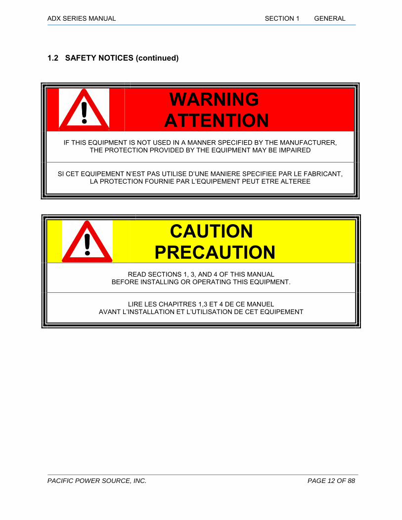
1.2 SAFETY NOTICES (continued)
CAUTION PRECAUTION
READ SECTIONS 1, 3, AND 4 OF THIS MANUAL
BEFORE INSTALLING OR OPERATING THIS EQUIPMENT.
LIRE LES CHAPITRES 1,3 ET 4 DE CE MANUEL
AVANT L’INSTALLATION ET L’UTILISATION DE CET EQUIPEMENT
WARNING ATTENTION
IF THIS EQUIPMENT IS NOT USED IN A MANNER SPECIFIED BY THE MANUFACTURER,
THE PROTECTION PROVIDED BY THE EQUIPMENT MAY BE IMPAIRED
SI CET EQUIPEMENT N’EST PAS UTILISE D’UNE MANIERE SPECIFIEE PAR LE FABRICANT,
LA PROTECTION FOURNIE PAR L’EQUIPEMENT PEUT ETRE ALTEREE

ADX SERIES MANUAL SECTION 1 GENERAL
PACIFIC POWER SOURCE, INC. PAGE 13 OF 88
1.2 SAFETY NOTICES (continued)
SAFETY SYMBOLS SIGNIFICATION DES SYMBOLES DE SECURITE
1 Alternating current
Courant Alternatif
2
Earth (ground) Terminal
Borne de Terre
3
Protective Conductor Terminal
Borne Protectrice de Conducteur
4
On (Supply)
Allumé (On, sous tension)
5
Off (Supply)
Eteint (Off, hors tension)
6
Caution, risk of electric shock
Attention, risque de choc électrique
7
Caution, risk of danger
Attention, danger
Table 1-2: SAFETY SYMBOLS

ADX SERIES MANUAL SECTION 1 GENERAL
PACIFIC POWER SOURCE, INC. PAGE 14 OF 88
1.3 GENERAL PRODUCT DESCRIPTION The ADX Power Source is a high-performance AC power conversion instrument. It is intended for indoor use and the chassis is designed to fit into a standard 19 inch instrument rack or to be used on any test bench surface. The power source is suitable for use as a frequency converter as well as for sophisticated AC test power generation.
These power sources are configured with a digital controller. Controller type is a modified UPC1 version for sophisticated programmable control. This controller provides all of the manual control capability, plus a wide variety of additional features including program storage and remote interface (Serial standard or GPIB optional).
All ADX models have dual-range output voltage capability, able to operate at either 0-150 volts or 0-300 volts. When operated in the high voltage range, the output may be used as either a single-ended or split-phase configuration. The phase separation of L1 and L2 is fixed at 180 degrees in that case.
Output power is 1kVA at any nominal input voltage from 115 to 240 Vac.
External Voltage Sense capability is provided and will display the actual voltage at the remote sense location. The CSC (Continuous Self Calibration) feature will allow the controller to regulate the voltage at the sense location.(CSC)
Output voltage and current metering is provided on the system display. Specifications of the metering functions are described in the UPC Series Operation Manual.
Figure 1-1: 110ADX POWER SOURCE - FRONT VIEW

PACIFIC POWER SOURCE, INC. PAGE 15 OF 88
SECTION 2
SPECIFICATIONS
2 SPECIFICATIONS This section states the electrical and mechanical specifications of the ADX Power Source. Some specifications are controller dependent and are noted as such.
2.1 ELECTRICAL SPECIFICATIONS
2.1.1 INPUT POWER REQUIREMENTS The following input power forms are accepted by the ADX
INPUT VOLTAGE
The Model ADX accepts any single phase input voltage of 115-240 Vac, 50Hz or 60 Hz Nominal and is tolerant of transient overvoltages typically present on the AC MAINS power distribution lines.
INPUT CURRENT
The input current required by the ADX varies as a function of the nominal AC input line voltage applied. Input current at rated output power and recommended input service is shown in the table below. Overload conditions will result in higher input currents that still fall within the recommended input service. The AC input current is electronically limited at 25Arms. This allows full rated power down to 115V -10% or 103VAC L-N (Low Line Voltage).
NOTE: Under low voltage input conditions, the max input current is electronically limited to 25ARMS maximum. At least 12AWG input cable wire is recommended.
Vin INPUT CURRENT SERVICE RECOMMENDED
100 VAC 23 Arms 30 A 110 VAC 21 Arms 30 A 120 VAC 18 Arms 30 A 200 VAC 13 Arms 20 A 208 VAC 12 Arms 15 A 220 VAC 11 Arms 15 A 230 VAC 10 Arms 15 A 240 VAC 9 Arms 15 A
Table 2-1: AC INPUT CURRENT FOR MODEL 115ADX
FIGURE 2.1 INPUT CURRENT VS. OUTPUT POWER FOR MODEL 115ADX
0.0
5.0
10.0
15.0
20.0
25.0
30.0
0% 20% 40% 60% 80% 100% 120%
100V120V200V

ADX SERIES MANUAL SECTION 2 SPECIFICATIONS
PACIFIC POWER SOURCE, INC. PAGE 16 OF 88
2.1.2 OUTPUT POWER OUTPUT VOLTAGE RANGE The standard output voltage ranges of the ADX are:
• 0-150 Vac when operated in low range (FORM 1)
• 0-300 Vac when operated in high range (FORM 2)
OUTPUT CURRENT FULL-RATED CURRENT
The full-rated output current of the ADX Power Source by model:
1φ 2φ
Model Iout, rms Imax, rms Iout, pk Iout, rms Imax, rms Iout, pk 110ADX 11 A 16.5 A 22 A 5.5 A 8 A 11 A 115ADX 16 A 24 A 32 A 8 A 12 A 16 A
Table 2-2: RATED OUTPUT CURRENT BY MODEL
Refer to the Rating Curve charts of Figure 2-1 for maximum output current at a specific output form, voltage, or power factor by model number.
OVERLOAD OPERATION
The ADX Power Source can deliver up to 120% of rated RMS output current at 25°C ambient temperature with any input line voltage of 100 Vac or higher. Elevated ambient temperature, low input voltage, or power factors between 0.8 and 1.0 will increase the internal dissipation of the power source and can cause shutdown due to over-temperature conditions. Length of time to reach over-temperature varies with the above parameters.
NOTE: All ADX Models are equipped with an over power protection feature. See section 4.16 for more details.

ADX SERIES MANUAL SECTION 2 SPECIFICATIONS
PACIFIC POWER SOURCE, INC. PAGE 17 OF 88
Figure 2-1: ADX OUTPUT RATING CURVES BY MODEL
Rated continuous load current as a function of Power Factor and Output Voltage – Nominal Input Line. Short term overloads to 120% are permitted. Operating time before thermal shutdown or circuit breaker trip will vary from seconds to several minutes depending upon line and temperature conditions.
150V Range
300V Range

ADX SERIES MANUAL SECTION 2 SPECIFICATIONS
PACIFIC POWER SOURCE, INC. PAGE 18 OF 88
2.1.3 OUTPUT POWER FACTOR The ADX Power Source is designed to operate into any load power factor. However, the Rating Curve charts of Figure 2.2 should be consulted for system capabilities at specific output power factors. The amount of heat generated by the amplifier increases as the power factor approaches 1.
2.1.4 OUTPUT FREQUENCY The output frequency range of the ADX Power Source is from 15 Hz to 600.0 Hz. There are 3 frequency spans:
NO FREQUENCY SPAN WAVEFORM STEPS METERING SAMPLES
1 15.00 – 150 Hz. 1024 512 2 15.00 – 300 Hz. 512 256 3 (default) 15.00 – 600 Hz. 256 128
2.1.5 OUTPUT DISTORTION The output distortion of the ADX Power Source is typically:
• less than 0.25% THD for output frequencies in the range of 15 to 200 Hz • less than 0.50% THD for output frequencies in the range of 200 to 600 Hz
Distortion specification applies under full Resistive load condition.
2.1.6 OUTPUT LOAD REGULATION Uncompensated load regulation of the ADX Power Source is typically:
• less than 1.5% for output frequencies in the range of 15 to 200 Hz • less than 2.0% for output frequencies in the range of 200 to 600 Hz
2.1.7 INPUT LINE REGULATION Input line regulation of the ADX Power Source is less than 0.1% for a ±10% change in line voltage (provided, input line voltage remains within the specified range).
2.1.8 OUTPUT BANDWIDTH The output bandwidth of the ADX Power Source is: Full Power: 15 to 200 Hz (±0.10 dB [± 1%])
200 to 600 Hz (±0.25 dB[± 3%])
Small Signal: 5 to 5,000 Hz (±0.5 dB [±6%]) ( rated at 10% of full-scale output voltage)
2.1.9 LOAD TRANSIENT RESPONSE Output load transient response and recovery time is approximately: 80 μsec. for a 10-90% load induced step transient
ADX SERIES MANUAL SECTION 2 SPECIFICATIONS
PACIFIC POWER SOURCE, INC. PAGE 19 OF 88
2.1.10 OUTPUT DC OFFSET The DC offset present on the output is: < 20 mVDC.
2.1.11 OUTPUT PROTECTION The output of the ADX Power Source is protected through the use of electronic current limiting. The output will automatically recover when the output fault is removed. Thermal overload protection is also provided. Refer to paragraph 4.11 for details.
The universal AC output socket that is located on the front of the ADX is limited to 10 A(RMS) operation. It is protected by a 10A circuit breaker located at the rear of the power source. If the current draw at the socket exceeds the 10A rating, the circuit breaker will disconnect power to the socket. Reduce the load at the socket and press the circuit breaker button to reset.
NOTE: The digital controller also provides programmable current limit. Refer to sections 4.14 and 4.15
2.1.12 OUTPUT CONTROL CHARACTERISTICS Output control characteristics, sync I/O signals, and metering capabilities are determined by the controller which is installed.
2.1.13 OUTPUT ISOLATION
The output of the ADX is galvanically isolated from the chassis and input power. Output Neutral to Chassis voltage is allowed to be 150 VAC, maximum. See paragraph 3.4, Output Power Connection, for grounding information.
2.2 MEASUREMENT SPECIFICATIONS The ADX Power Source controller is equipped with a precision measurement system that measures the output voltage, current and power of the power source.
2.2.1 VOLTAGE MEASUREMENT (Vrms) Vrms Meter Range: 354 VLN, 708 VLL A.C.
Display Resolution: 0.1 VAC rms.
The Remote interface may provide up to 3 digits of precision (digits to the right of the decimal point).
Accuracy: ± 0.2% of Full Scale, ± calibration reference @ 25ºC.
NOTE: Some load voltage may be displayed with NO LOAD attached due to the sensitivity of the metering circuits.
NOTE: Power source voltmeter scaling is internally fixed at 50:1 e.g. 50 VAC at load = 1 VAC input to UPC = 50 VAC displayed.:

ADX SERIES MANUAL SECTION 2 SPECIFICATIONS
PACIFIC POWER SOURCE, INC. PAGE 20 OF 88
2.2.2 CURRENT MEASUREMENT (Arms) Three ammeter inputs are provided, one per phase. Both Peak and RMS values are displayed. Current crest factor is displayed as the ratio: Ipk/Irms
Amp Meter range: Amps-to-Volts-Ratio x 10 (divided by 3 if 3 Ф form is used)
DISPLAY Range: 00.01 – 99.99 Amps rms or Peak
DISPLAY Resolution: 0.001 Amps rms or Peak.
Accuracy: ± 0.2% of Full Scale, ± calibration reference, @ 25ºC.
NOTE: The AMPS TO VOLTS RATIO is set and displayed with the UPC STATUS display (fn,3,3)
NOTE: Some load current may be displayed with NO LOAD attached due to the sensitivity of the metering circuits.
2.2.3 APPARENT POWER MEASUREMENT (VA) kVA metering is provided by multiplying the metered volts times the metered amps values. Display range and resolution is X.XXX kVA. The Remote interface may provide 3 digits of precision (digits to the right of the decimal point).
Accuracy is ± 1% of full scale over the full range of ambient conditions
2.2.4 TRUE POWER MEASUREMENT (W) True power metering is provided by integrating volts and amps measurements. Display range and resolution is X.XXX kW. The Remote interface may provide 3 digits of precision (digits to the right of the decimal point).
Accuracy is ± 1% of full scale over the full range of ambient conditions
2.2.5 POWER FACTOR MEASUREMENT (PF) Power factor is displayed as the ratio: kW / kVA. Display range and resolution is X.XXX. The Remote interface may provide 3 digits of precision (digits to the right of the decimal point).
Accuracy is ± 1% of full scale over the full range of ambient conditions.
2.2.6 FREQUENCY DISPLAY SPECIFICATIONS
The frequency in the metering display is calculated from program data. Internally, there are 3 Frequency Spans, each with a different resolution. The controller typically performs auto-ranging based on the selected frequency but the Frequency Span can be specified.
Range: 15.00 – 600 Hz.. Resolution: 10.00 to 99.99 Hz. 0.01 Hz.
100.0 to 600.0 Hz. 0.1 Hz.
Accuracy: (over the full range of ambient conditions) ± 0.01% of full scale

ADX SERIES MANUAL SECTION 2 SPECIFICATIONS
PACIFIC POWER SOURCE, INC. PAGE 21 OF 88
2.3 MECHANICAL SPECIFICATIONS The ADX Power Source mechanical characteristics are:
2.3.1 DIMENSIONS AND WEIGHT
Parameter Value Notes Height: 3.5" / 89 mm 2U rack mountable units Width: 19.00" / 483 mm Front panel with mounting brackets 16.75" / 426 mm Main chassis Depth: 23.62" / 600 mm Measured from back side of front panel, excludes
terminal blocks Weight: 40 lbs. / 18.2 kg
Table 2-3: DIMENSION AND WEIGHT

ADX SERIES MANUAL SECTION 2 SPECIFICATIONS
PACIFIC POWER SOURCE, INC. PAGE 22 OF 88
2.3.2 DIMENSIONS DRAWINGS
–
FRONT VIEW
RIGHT VIEW
REAR VIEW
Figure 2-2: OUTLINE DRAWINGS
AIR INTAKE
23.82 0.86 1.22
TB5: REMOTE CONTACTOR CONTROL
CIRCUIT BREAKER FOR UNIVERSAL AC OUTPUT SOCKET
EXHAUST AIR OUTPUT
AUX I/O
GPIB/RS232
INPUT TERMINAL COVER
3.00
3.50
INPUT AC CIRCUIT BREAKER
UPC CONTROLLER UNIVERSAL AC OUTPUT
16.75 18.34 19.00

ADX SERIES MANUAL SECTION 2 SPECIFICATIONS
PACIFIC POWER SOURCE, INC. PAGE 23 OF 88
2.3.3 INPUT POWER CONNECTION Input power is brought into the ADX at the Input Power terminal block on the rear panel.
2.3.4 OUTPUT POWER CONNECTION Output power is taken from the ADX Power Source via rear panel mounted terminal blocks. Remote Sense terminals are also provided at this terminal block.
Terminal block TB5 on the rear of the ADX may be used to remotely enable/disable the output of the power source. An electrical connection between terminals TB5-1 and TB5-3 enables the output of the ADX allowing normal operation from the front panel or remote interface. An open connection between TB5-1 and TB5-3, disables the output of the ADX. The ADX is supplied with a jumper installed in TB5 such that the output is enabled. That jumper may be replaced by a switch or relay which can operate as a safety interlock or remote disconnect.
2.3.5 CHASSIS SLIDE MOUNTS The ADX Power Source is designed to accept slide rails for mounting in a 19” Instrument Cabinet. These rack slides can be provided as a cost option. Contact your local sales representative or the Pacific Power Source Sales Office.
2.4 ENVIRONMENTAL SPECIFICATIONS
2.4.1 TEMPERATURE RANGE The ADX Power Source is rated for full operation in ambient temperatures of:
0 - 40°C, relative humidity in the range of 0 - 95%, non-condensing.
Operation from 40°C to 55°C is permitted with output power decreasing linearly with increasing ambient temperature. Available power at 55°C is 600W.
2.4.2 COOLING The ADX Power Source utilizes thermally regulated forced-air cooling to maintain proper temperatures throughout. The maximum airflow is 240 CFM.
2.4.3 ALTITUDE The ADX Power Source is rated for full operation at altitudes of: 0 – 10,000 feet/3,000m.
2.4.4 POLLUTION DEGREE The ADX Power Source is rated for full operation in environments of mild pollution severity and humidity referred to as Pollution Degree 2. These conditions are typically present in office, laboratory and ATE environments. Normally only nonconductive pollution occurs. Temporary conductivity caused by condensation is to be expected.
2.4.5 THERMAL PROTECTION Temperature sensors are installed in the power assemblies. If safe operating temperature is exceeded, the output is opened and the Shutdown LED on the front panel, is lighted. A shutdown fault must be reset to restore normal operation. See paragraph 4.5 for details.

PACIFIC POWER SOURCE, INC. PAGE 24 OF 88
SECTION 3
INSTALLATION
3 INSTALLATION This section describes the installation of the ADX AC Power Source.
3.1 CHASSIS PLACEMENT The ADX Power Source is designed to operate as a bench-top unit, or to fit into a standard 19-inch rack. Provisions for mounting slide rails are included on the chassis.
WARNING ATTENTION
THE ADX WEIGHS 40 lbs [18.2 kg] USE EXTREME CARE WHEN MOVING THE UNIT IN ORDER TO REDUCE CHANCE OF PHYSICAL INJURY.
WHEN MOUNTING SLIDE RAILS TO THE ADX CHASSIS, MAXIMUM SCREW LENGTH IS 8 mm.
LA ADX PESE 40 lbs [18.2Kg] VEILLEZ A PRENDRE TOUTES LES PRECAUTIONS NECESSAIRES DURANT LE TRANSPORT DE
L’EQUIPEMENT AFIN DE MINIMISER TOUT RISQUE D’ACCIDENT PHYSIQUE.
LA LONGUEUR MAXIMUM DES VIS DESTINEES A FIXER LES GLISSIERES SUR LE CHASSIS DE LA ADX EST DE 8MM.
- - - - - - - - P A C K I N G N O T I C E - - - - - -
It is the customer's responsibility to insure that units are adequately packaged when they are moved to a different location. The ADX should always be packaged in the original shipping container when moved or returned to the factory for service.
- - - - - - - - - - - - - - - - - - - - - - - - - - - - - - - - - -

ADX SERIES MANUAL SECTION 3 INSTALLATION
PACIFIC POWER SOURCE, INC. PAGE 25 OF 88
Once the unit has been removed from its shipping container, select an appropriate location for the unit. Key points to consider when locating the chassis are:
1. PROXIMITY TO THE LOAD - The power source should be located as close to the load as possible. This helps to reduce distribution losses. These losses increase as the output frequency increases.
2. VENTILATION - The chassis requires good ventilation to adequately cool the internal components. Airflow should allow 240 CFM. The air intake is located on both sides near the front. A minimum clearance of two inches on each side and 12 inches to the rear is required for proper operation.
When the unit is placed in a 19 inch rack, it must be supported by either chassis slides or full depth angle brackets. The front panel alone will not support the weight of the chassis. Chassis slides are available from Pacific Power Source as a cost option. Call factory service for details.
After the location for the chassis is selected, verify that the input voltage of the power source is correct. Input voltage is stated on the system ID label.
After the input voltage form has been verified as correct, slide the chassis into the rack or set it into its final position. Make input and output connections as stated in paragraphs 3.3 and 3.4, respectively.
If either the Remote Interface (GPIB or RS-232) or External Sense feature is to be used, refer to paragraphs 3.5 and 3.7 for connection information.
Before activating the ADX output, check that the output voltage is correct to prevent possible damage to any attached equipment.
3.2 OUTPUT RANGE CONFIGURATION The ADX is a dual-range power source. The output voltage range is selected by the FORM setting selected in the UPC controller. See the UPC Series Operation Manual for setup. The standard output configurations are:
FORM 1: 0 – 150 Vac
FORM 2: 0 – 300 Vac
AMPS TO VOLTS RATIO:
For accurate current meter display, the Amps to Volts Ratio Setting of the UPC is always set to 5 for the Model ADX.

ADX SERIES MANUAL SECTION 3 INSTALLATION
PACIFIC POWER SOURCE, INC. PAGE 26 OF 88
3.3 INPUT POWER CONNECTION The ADX Power Source has been designed to accept most standard single-phase input voltage forms. This is accomplished by incorporating an active wide-range power factor correction circuit. Any single-phase input voltage from 115 to 240 Vac ±10% can be applied. No range selection is required.
CAUTION PRECAUTION
CONNECTION OF THIS UNIT TO IMPROPER INPUT VOLTAGE
WILL CAUSE CATASTROPHIC DAMAGE TO THE POWER SOURCE. READ THE INPUT VOLTAGE LABEL AND CONNECT TO THAT INPUT VOLTAGE ONLY.
IF THERE ARE ANY QUESTIONS, CONTACT THE FACTORY
LE RACCORDEMENT A UNE TENSION D’ENTRÉE INCORRECTE PEUT CONDUIRE A DES DOMMAGES CATASTROPHIQUES DE L’EQUIPEMENT. LIRE L’ETIQUETTE INDIQUANT LA TENSION D’ENTRÉE ET
RACCORDER L’EQUIPEMENT A CETTE TENSION D’ENTRÉE UNIQUEMENT. POUR TOUTES QUESTIONS, CONTACTER L’USINE
WARNING ATTENTION
LETHAL VOLTAGE IS PRESENT AT INPUT TERMINALS OF THIS DEVICE.
ALWAYS CONNECT "PE or GND" TERMINAL TO EARTH POTENTIAL.
FAILURE TO DO SO WILL CREATE A SHOCK HAZARD. TENSION A CARACTERE MORTEL PRESENTE SUR LES BORNES DE SORTIE DE CET EQUIPEMENT.
LA MISE A LA TERRE DES BORNES ‘PE ou GND’ EST IMPERATIVE. UN MANQUEMEMT A CETTE REGLE PEUT ENTRAINER UN RISQUE DE CHOC.

ADX SERIES MANUAL SECTION 3 INSTALLATION
PACIFIC POWER SOURCE, INC. PAGE 27 OF 88
The ADX Power Source is provided with a terminal block for input power connection. This allows hard-wired connection for system applications or attachment of an appropriate input power cord. Refer to Paragraph 2.1.1 for minimum input service requirements for various input voltages and size the input cable wires accordingly.
Refer to the table below for the proper wire color of each connection.
Wire Color( USA) Wire Color( Europe) LINE ( HI ) Black Brown
NEUTRAL ( LO ) White Blue GROUND ( PE * ) Green Green-Yellow
* Protective Earth NOTE: It is the user's responsibility to meet all local and national electrical codes when installing
this equipment. This equipment is classified as a permanently connected device. As such, proper installation requires the use of a circuit breaker in the building wiring installation which is sized appropriately to protect the facility wiring. A switch or circuit breaker shall be in close proximity to the equipment and marked as the disconnecting device for the equipment.
Figure 3-1: INPUT AND OUTPUT CONNECTIONS
TO USER
GROUND
CHASSIS CONNECTION ATTACHED TO STUD AS SHOWN
INPUT LINE
PE/GND
HI
LO

ADX SERIES MANUAL SECTION 3 INSTALLATION
PACIFIC POWER SOURCE, INC. PAGE 28 OF 88
3.4 OUTPUT POWER CONNECTION The ADX provides output connections at both the front and rear of the chassis. Front panel load connection is through a universal outlet socket. Available current at this socket is 10 amps max., protected by a circuit breaker located at the rear of the unit. Rear panel load connection is available through a terminal block which is rated for the full output current of the ADX. Figure 3.3 illustrates connection of a single-phase load to the ADX rear-panel terminal. Refer to Paragraph 2.1.2 for minimum output service requirements for various output voltages and size the output wires accordingly.
NOTE: No metal parts should be touching the output terminals as dangerous voltage
may be present. It is the user's responsibility to meet all local and national electrical codes when installing this equipment.
For safe operation, the PE ground terminal should always be connected to the chassis of the load.
Output power should also be referenced to the chassis, unless otherwise demanded. The output is isolated but insulation specifications require that no more than 150 Vac be present between the output neutral (LINE2 or N) and chassis. For single-phase applications, a jumper should be attached between LINE2 and PE/GND. For applications using the high range as a split-phase configuration, the jumper should be attached between N and PE/GND.
Refer to Paragraph 3.7 for connection of the External Sense connection, when used.
The ADX Power Source output can be configured for single and split phase voltage forms. Figure 3.4 is a simplified block diagram of the possible output architectures.
The FORM1 (low range, 0-150 Vac) mode of operation is a one vector output form, single-phase only. The power amplifiers are connected in parallel to form one output vector. The load can be attached from LINE1 to LINE2 or LINE1 to N. In this form, LINE2 and Neutral are connected. This output form is capable of 0-150 VACl-n.
The FORM2 (high range, 0-300 Vac) mode of operation is a two vector output form where the vectors are separated by 180° and equal in amplitude. This output form uses power amplifiers in pairs, one for each vector.
For single phase 0-300 VACl-l, connect the load from LINE1 to LINE2.
For loads that require three connections (L1-N-L2), commonly referred to as "Split-Phase" power, LINE 1 and LINE 2 are equal in voltage and 180 degrees apart, referenced to Neutral. Loads can be connected from either LINE to Neutral or from LINE1 to LINE2.
WARNING ATTENTION
LETHAL VOLTAGES MAY BE PRESENT AT THE OUTPUT TERMINALS OF THIS DEVICE! REFER OUTPUT CONNECTION TO A QUALIFIED ELECTRICIAN.
DES TENSIONS A CARACTERE MORTEL PEUVENT ETRE PRESENTES SUR LES BORNES DE SORTIE DE CET EQUIPEMENT! VEUILLEZ VOUS REFERER A UN ELECTRICIEN QUALIFIE POUR LA
CONNECTION DES BORNES DE SORTIE

ADX SERIES MANUAL SECTION 3 INSTALLATION
PACIFIC POWER SOURCE, INC. PAGE 29 OF 88
FORM1 OUTPUT
SINGLE PHASE, LOW RANGE FORM2 OUTPUT
SINGLE PHASE, HIGH RANGE OR
SPLIT PHASE
Figure 3-2: ADX-SERIES SYSTEM ARCHITECTURE
3.5 REMOTE INTERFACE The ADX with the UPC Series programmable controller is supplied with an RS232 serial remote interface.
Interface Type Notes RS232 RS-232 Interface. D-Sub 9 Pin connector located on rear panel.
(Depicted in Figure 3.4) Pin out DB9 Connector: Pin 2: Receive Data Pin 3: Transmit Data Pin 5: Signal Ground All other pins are N/C
Table 3-1: RS232 PIN OUT
Connection and communication information relative to these interfaces can also be found in the UPC Series Operation Manual.
3.6 AUX I/O INSTALLATION On the rear panel J5, the AUX I/O (Auxiliary Input/Output) connector, contains synchronizing outputs (digital), external oscillator inputs (analog), and amplitude modulation inputs (AM, analog). These are extremely useful in certain test applications. The use of any of these signals is optional and connection to these points is required only when these features are used.
All signals contained within the AUX I/O connector are low-level (less than ±15 VDC) and are referenced to chassis (earth) ground reference.

ADX SERIES MANUAL SECTION 3 INSTALLATION
PACIFIC POWER SOURCE, INC. PAGE 30 OF 88
The AUX I/O connector is a DB-25S connector. A DB-25P connector is required for connection to AUX I/O connector.
Figure 3-3: AUX I/O DB25S PIN OUT DIAGRAM
ADX SERIES MANUAL SECTION 3 INSTALLATION
PACIFIC POWER SOURCE, INC. PAGE 31 OF 88
3.6.1 ANALOG INPUTS
Three Auxiliary Inputs are provided on J5, one per phase. The Auxiliary Inputs are AC coupled and algebraically summed to the Oscillator signals produced by the UPC. Note that the Auxiliary Inputs can be used as external oscillator inputs simply by programming the UPC for 0 VAC output.
Auxiliary Input voltage range (Vaux): ± 10Vpk (20Vpk-pk)
Input impedance: 600 ohms
Small Signal Gain Bandwidth: > 100 kHz. (auxiliary inputs)
Form 1:
Power source OUTPUT VOLTAGE = Vprogram + (Vaux x 25 x XFMRratio).
Form 2:
Power source OUTPUT VOLTAGE = Vprogram + (Vaux x 50 x XFMRratio).
Three AM Inputs are provided on J5, one per phase. Varying DC voltage may be used to Amplitude Modulate the output.
AM Input voltage range (Vam): ± 10Vdc (20Vpk-pk)
Input impedance: 600 ohms
Power source OUTPUT VOLTAGE = Vprogram + (Vam/10 x (204.5 x XFMRratio))
The maximum voltage is limited by the output voltage range of the power source
NOTE: Attempting to drive the OUTPUT VOLTAGE beyond the voltage range of the power source will result in a clipped (distorted) output waveform.
3.6.2 DIGITAL OUTPUTS
J5 digital outputs are 0 to 5 VDC, positive logic.
Logic outputs are:
Transient Pedestal: Not supported on ADX models
DRM: frequency generating clock, depending on FSPAN (4.6.4, 4.6.3.2)
SYNC OUT: Positive Zero Crossing (0º) of Phase A analog output

ADX SERIES MANUAL SECTION 3 INSTALLATION
PACIFIC POWER SOURCE, INC. PAGE 32 OF 88
3.7 EXTERNAL SENSE CONNECTION The ADX Power Source includes connections for external sense of the output voltage. This allows measurement of the output voltage at an external sense point. This feature can be completely disabled, so the wiring detailed in this paragraph is optional.
Figure 3.4 shows external sense wiring for the ADX. There is very little current flowing through the External Sense Feedback lines. Standard 22 AWG, 600 Volt control wire is recommended for this application. Twisting the External Sense wiring is recommended and, in some cases, can improve performance. In noisy environments, shielding may become necessary to minimize interference. If shielded cable is used, be sure to ground the shield at one end only to prevent the possibility of creating a ground loop.
WARNING ATTENTION
LETHAL VOLTAGES ARE PRESENT AT THE OUTPUT TERMINALS OF THIS DEVICE! WHEN EXTERNAL SENSE IS CONNECTED, THE SAME VOLTAGE APPEARS ON THE SENSE TERMINALS.
REFER OUTPUT CONNECTION TO A QUALIFIED ELECTRICIAN.
DES TENSIONS A CARACTERE MORTEL SONT PRESENTES SUR LES BORNES DE SORTIE DE CET EQUIPEMENT! SI LES SENSE EXTERNES SONT RACCORDEES, LES MEMES TENSIONS
SONT PRESENTES SUR LES BORNES DE SENSE. VEUILLEZ VOUS REFERER A UN ELECTRICIEN QUALIFIE POUR LA CONNECTION DES BORNES DE SORTIE
External Sense
Figure 3-4: EXTERNAL SENSE WIRING

PACIFIC POWER SOURCE, INC. PAGE 33 OF 88
SECTION 4
OPERATION
4 OPERATION This section describes the operation of the ADX AC Power Source UPC-1 controller.
4.1 OVERVIEW The ADX is operable either from its front panel keyboard (LOCAL CONTROL operation) or by its Data Bus (REMOTE CONTROL operation, Serial or IEEE-488/GPIB). A host computer can force REMOTE CONTROL when the ADX controller is displaying a Metering display. LOCAL CONTROL can be resumed either by a bus command (GoTo Local) or by manually pressing the LOCAL key. The host computer can force retention of REMOTE CONTROL by issuing a lockout command (Local LockOut (LLO), thereby preventing manual override.
When using the UPC controller, it is useful to think of it as being in one of 4 operating "modes" when in LOCAL CONTROL.
1. MANUAL OPERATE 2. PROGRAM OPERATE 3. PROGRAM EDIT 4. SETUP
MANUAL MODE is control of the operating characteristics via the front panel keyboard. Voltage and Frequency parameters are manually set from the front panel. Volts and Frequency may be directly entered through the numeric keyboard or they may be smoothly varied by use of the "slew" controls (up and down arrows). The V/I METER display (default display) shows both command values and metered values.
The PROGRAM OPERATE mode attempts to simplify certain test operations by allowing the operator to execute pre-stored setups (combinations of Volts, Frequency and Current limit). A stored program can be executed simply by pressing PROGRAM, entering a program number, then EXECUTE. Up to 99 programs can be stored as desired. After a program is called up by number, EXECUTE causes the base program parameters to be executed. These base parameters are commonly referred to as "Steady-state" parameters.
The PROGRAM EDIT mode allows the operator to create new programs, or change existing programs. It is noteworthy that programs other than any program actively executing, can be edited without disrupting power source output. For example, if program 15 is executing, program 23 can be edited without interrupting execution of program 15.
The SETUP MODE is used to make changes in system configuration. Examples are:
• Copy and Delete Programs • Set Min. and Max. Voltage Limits • Set Min. and Max. Frequency Limits • Engage and Disengage CSC (Continuous Self Calibration) • Set the Metering Sense Point – Internal or External • Set Slew rates • Change Frequency Span • Enable keyboard lockout • Set initial power on output voltage • Monitor Controller (UPC) and Power Source status • View Firmware Version

ADX SERIES MANUAL SECTION 4 OPERATION
PACIFIC POWER SOURCE, INC. PAGE 34 OF 88
• Enable Calibration Mode for Output and Metering • Set Serial Interface Parameters or GPIB Device Address • Erase Memory • Set Amps-to-Volts Current Metering Ratio
4.2 SELECTING OPERATING MODES On first turn-on the system will operate using a set of default parameters stored in memory. The display will be the V/I METER display. This is the default - and most frequently used - display. It shows all basic operating parameters, and in the lower left portion shows the operating mode. All operating modes can be accessed from the V/I METER display. If the V/I METER display is not active, pressing CLEAR a few times will always return to the V/I METER display.
MANUAL OPERATION (4.3) - is available by pressing V or F for voltage or frequency adjustments. An LED will light above a pressed key to indicate an active selection. The selected parameter can then be changed by typing a new value and pressing EXECUTE or holding one of the SLEW keys (︿ or ﹀).
PROGRAM OPERATION (4.4) -requires pressing PROGRAM, select a program number (1-99) and press ENTER to display the values stored in that program. Pressing EXECUTE will then cause the UPC to use those values. Note that pressing TRANS has no function on the ADX as this capability is not present.
PROGRAM EDIT (4.5) – is accessed by pressing PROGRAM, select a program number (1-99) and press ENTER to display the values stored in that program. Press EDIT to allow changes to the values stored in that program, ENTER to move the cursor through the screen, and STORE to save the values.
SETUP MODE (4.6) Pressing the fn key presents the menu list of SETUP features. It is used to copy and delete programs, erase memory, set meter sense points, toggle CSC on or off, min and max frequency and min and max voltage. Calibration for metering may also be performed. Status is given for system information such as firmware version, GPIB device address or Serial Interface parameters, transformer ratio, amps to volts ratio, number of Power Source amplifiers and current transformer location
NOTE: The five keys in the lower right portion of the keyboard (highlighted with a different color) are executive keys. Every attempt has been made to ensure that:
• In order to change power applied to the load one of these keys must be pressed.
• Whenever one of these keys is pressed, power to the load may be changed.
This operational feature has been designed to help keep the user from accidentally pressing the wrong key and unintentionally changing power to the load.
Remember! When you press a BLACK key something will probably happen to change output power.

ADX SERIES MANUAL SECTION 5 REMOTE CONTROL
PACIFIC POWER SOURCE, INC. PAGE 35 OF 88
4.3 FRONT PANEL CONTROLS
The location of the front panel controls and indicators of the ADX Power Source is shown below. A brief description of each is also given. Figure 4.1 is a front view of the ADX unit.
1. INPUT POWER SWITCH (Circuit Breaker @ 30A) Circuit Breaker used as the main input ON/OFF control and protects the power source from drawing excessive input current from the input AC line.
2. LCD Display. All settings and measurement data is display on the 4 x 40 character backlit LCD Display.
3. Numeric Keypad – Parameter values for any setting may be entered directly using the 0-9 keypad. A decimal point and a “+/-“ key is located in this area as well. The LOCAL/REMOTE, HELP, DISPLAY and FUNCTION (fn) key are located directly to the left of the numeric keypad.
4. EXECUTE, TRANS and OUTPUT ENABLE keys. Black keys are used to change the output. Note that the TRANS key functionality is not implemented in the ADX series.
5. OUTPUT ON/OFF Key. This switch opens the output relay and cannot be overridden by the remote control interface. It provides a means of physically disconnecting the power source from the load. This switch must be in the ON/AUTO position to control the output relay via either the OUTPUT ENABLE button or the remote control interface.
OUTPUT POWER SWITCH and INDICATORS Switch used to control the output relay of the ADX-Series Power Source. An indicator shows the status of the output. The power source will shut down for over-temperature or other internal faults if they occur. A shutdown state is reset when the Output Power Switch is set to OFF and the fault has cleared.
6. UNIVERSAL OUTLET SOCKET: This socket allows most plug to be used to connect a load. Note that this socket is fuse limited to 10A rms max. For full current output on higher power models, use the rear panel output terminals to connect the load.
Figure 4-1: FRONT PANEL CONTROLS
1 5
2
4
3
6

ADX SERIES MANUAL SECTION 4 OPERATION
PACIFIC POWER SOURCE, INC. PAGE 36 OF 88
4.4 MANUAL MODE This section describes operation in Manual Mode. In this mode you may slew or directly enter voltage or frequency values. Parameters other than volts and frequency can only be changed by editing and executing a steady-state Program.
The V/I METER display will indicate MANUAL MODE in the lower left corner of the display.
4.4.1 METERING DISPLAYS There are three primary metering displays. Pressing the DISPLAY key will cycle through the metering displays. If a display other than a metering display is active, pressing the DISPLAY key will abort common edit functions and return to a metering display.
The V/I METER display indicates FREQuency, metering SENSE point (INTernal or EXTernal) and MANUAL MODE or PROGRAM # executing. This display meters true RMS Voltage (line to neutral and line to line) and true RMS current.
V/I METER: ENTRY: 120.0 FREQ=60.00 Va=120.0 SENSE=INT MANUAL MODE Ia=00.00
The POWER METER display meters kVA, true kW and PF.
POWER METER: PHASE A KVA 0.000 KW 0.000 PF 1.000
The AMPS METER display meters RMS amps, PEAK amps and CREST FACTOR.
AMPS METER: PHASE A RMS 0.00 PEAK 0.00 CREST FACTOR 1.00

ADX SERIES MANUAL SECTION 5 REMOTE CONTROL
PACIFIC POWER SOURCE, INC. PAGE 37 OF 88
4.4.2 VOLTAGE ENTRY In MANUAL MODE, to change voltage from any meter display, light the V LED by pressing the V key.
Pressing an ARROW key (︿ or ﹀) causes selected voltages to slew up or down. Entering a number then pressing EXECUTE causes selected voltages to change to the new value. The upper right corner of the display shows the most recently entered voltage.
For example: To change to 125 volts, light the V LED by pressing the V key. Type 125 and press EXECUTE. The Power Source should now be generating 125 volts.
V/I METER: ENTRY: 125.0 FREQ=60.00 Va=125.0 SENSE=INT MANUAL MODE Ia=00.0
4.4.3 FREQUENCY CONTROL In MANUAL MODE, to change frequency from any meter display, light the F LED by pressing that key.
Pressing an ARROW key (︿ or ﹀) causes the frequency to slew up or down. Entering a number then pressing EXECUTE causes the frequency to change to the new value. The upper right corner of the display shows the most recently entered frequency.
For example to change to 60.50 Hz. light the F LED: enter 60.50 and press EXECUTE. The Power Source should now be generating 60.50 Hz.
V/I METER: ENTRY: 60.50 FREQ=60.50 Va=120.0 SENSE=INT MANUAL MODE Ia=00.0

ADX SERIES MANUAL SECTION 4 OPERATION
PACIFIC POWER SOURCE, INC. PAGE 38 OF 88
4.5 PROGRAM MODE Program Operate Mode allows pre-stored program execution including transients.
Not all Program Operate features are available on the of the ADX UPC1 controller. Transient programming is not available.
When the V/I METER display is active the lower left corner will indicate the number of the PROGRAM currently being executed
4.5.1 PROGRAM EXECUTION To achieve Program Operate Mode, from any meter display press the PROGRAM key. This will cause the PROGRAM display to become active. The last or currently executing program will be displayed. You may enter a new program number then press ENTER to view it.
PROGRAM: #1 FORM=1 COUPLING=DIRECT FREQ=60 Va=1200 WFa=1 #SEGS=0 Ilim=50
Pressing EXECUTE now will cause that program to be executed and the V/I METER display to be active.
V/I METER: FREQ=60.00 Va=120.0 SENSE=INT PROGRAM #1 Ia=00.0
4.5.2 PROGRAM EDITING The Program Edit Mode allows program definition and editing. To achieve Program Edit Mode, from any meter display press the PROGRAM key, program number, ENTER key then EDIT key. The cursor will move to FORM.
PROGRAM: #1 FORM=1 COUPLING=DIRECT FREQ=60 Va=120 WFa=1 #SEGS=0 Ilim=50
The following may be programmed:
FORM: Enter 1 or 2 Phase output FORM.
FORM 1 enables Single phase output and is connected to the 1 Phase Output Relay. Only the 1Ф Output Terminal will become active. 1 Phase loads must be connected between the 1Ф Terminal and the “N” (neutral) Terminal.
FORM 2 enables the high range Split/Single phase output. The Power Source output is connected to the 3 Phase Output Relay. Only ФA and ФB Output Terminals will

ADX SERIES MANUAL SECTION 5 REMOTE CONTROL
PACIFIC POWER SOURCE, INC. PAGE 39 OF 88
become active and are 180º out of phase. Voltages are programmed phase to phase. This may be called split phase and can be loaded between the ФA and ФB Output Terminals or from either phase to “N” (neutral) at half voltage.
COUPLING:
On ADX models, this setting is fixed to DIRECT.
FREQ:
Any desired output frequency from 15.00 to 1200 Hz. may be entered. The FREQUENCY SPAN must be set for the correct range before the Program can be EXECUTED.
RANGE RESOLUTION
15.00 - 99.99 Hz. 0.01 Hz.
100.0 – 600.0 Hz. 0.1 Hz.
Va, Vb:
Line to neutral voltages are entered for 1Ф while line to line voltages are entered for 2Ф Forms.
WFa1:
This field is fixed to Waveform 1. Waveform 1 is a sine wave and is the only waveform available.
#SEGS:
Not Editable. Fixed to zero (0).
Ilim:
Programmable current limit can be set as desired. The range will change depending upon which Power Source the UPC is controlling. This function is average responding, RMS programmed.
Pressing STORE at any time during editing will cause the program to be stored. The V/I METER display will become active.
Pressing EXECUTE at any time during editing will cause the program to be stored and executed. The V/I METER display will become active.

ADX SERIES MANUAL SECTION 4 OPERATION
PACIFIC POWER SOURCE, INC. PAGE 40 OF 88
4.6 SETUP MODE SETUP MODE is used to:
• Copy and Delete Programs • Set Min. and Max. Voltage Limits • Set Min. and Max. Frequency Limits • Engage and Disengage CSC (Continuous Self Calibration) • Set the Metering Sense Point – Internal or External • Set Slew rates • Change Frequency Span • Enable keyboard lockout • Set initial power on output voltage • Monitor UPC and Power Source status • View Firmware Version • Enable Calibration Mode for Metering • Set Serial Interface Parameters or GPIB Device Address • Erase Memory • Set Amps-to-Volts Current Metering Ratio • Define Current Transformer Location • Display the Number of Power Source Amplifiers
From any meter display, press the fn key to enter SETUP MODE.
SETUP MENU: 1 PROGRAM 2 GENERAL 3 CALIBRATION
NOTE: Holding the fn key while applying power to the UPC will bring up the SETUP MENU directly, without any Program executing and therefore no output. The SETUP functions can be accessed as described below. If CLEAR is pressed, the UPC will indicate “NO PROGRAM RUNNING”. Select a PROGRAM and EXECUTE to initiate normal operation and display the V/I screen

ADX SERIES MANUAL SECTION 5 REMOTE CONTROL
PACIFIC POWER SOURCE, INC. PAGE 41 OF 88
4.6.1 PROGRAM SETUP PROGRAM SETUP is used to copy and delete programs and erase memory.
From any METER display (V/I, AMPS or POWER), press the fn key to enter SETUP MODE. From the SETUP display, press 1 to enter PROGRAM SETUP.
PROGRAM MENU: 1 COPY PROGRAM 2 DELETE PROGRAM 3 INITIALIZE PROGRAMS, SETUP
COPY PROGRAM is used to copy Program data.
From any METER display (V/I, AMPS or POWER), press the fn key to enter SETUP MODE. From the SETUP display, press 1 to enter PROGRAM SETUP. From the PROGRAM SETUP display, press 1 to enter COPY PROGRAM.
COPY PROGRAM: RANGE SOURCE PROGRAM NUMBER=0 0-103 DESTINATION PROGRAM NUMBER=1 1-99 PRESS STORE TO COPY.
SOURCE PROGRAM NUMBER:
0 will copy the present MANUAL MODE operating parameters.
1-99 are user created programs that may be edited or copied to and from.
DESTINATION PROGRAM NUMBER:
1-99 are user created programs that may be edited or copied to and from.
NOTE: You cannot copy to a program that is currently executing.
DELETE PROGRAM is used to delete programs. This is useful to free up memory.
From any METER display (V/I, AMPS or POWER), press the fn key to enter SETUP MODE. From the SETUP display, press 1 to enter PROGRAM SETUP. From the PROGRAM SETUP display, press 2 to enter DELETE PROGRAM.
DELETE PROGRAM: RANGE PROGRAM TO DELETE=1 1-99 PRESS STORE TO ERASE.
NOTE: You cannot delete a program that is currently executing.
INITIALIZE PROGRAMS will erase all user entered programs and reset Program 1 and Setup values to their original factory defaults. This is convenient if you want to reset the UPC to the factory state without affecting the calibration.
ADX SERIES MANUAL SECTION 4 OPERATION
PACIFIC POWER SOURCE, INC. PAGE 42 OF 88
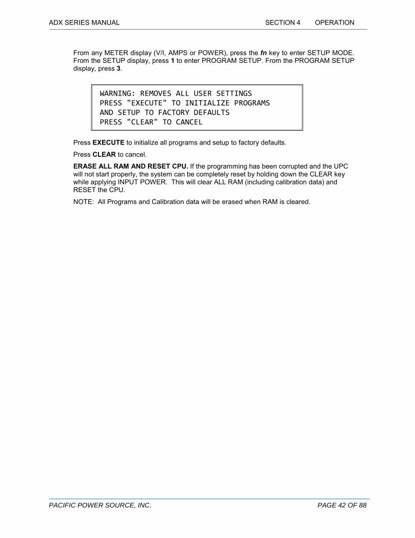
From any METER display (V/I, AMPS or POWER), press the fn key to enter SETUP MODE. From the SETUP display, press 1 to enter PROGRAM SETUP. From the PROGRAM SETUP display, press 3.
WARNING: REMOVES ALL USER SETTINGS PRESS "EXECUTE" TO INITIALIZE PROGRAMS AND SETUP TO FACTORY DEFAULTS PRESS "CLEAR" TO CANCEL
Press EXECUTE to initialize all programs and setup to factory defaults.
Press CLEAR to cancel.
ERASE ALL RAM AND RESET CPU. If the programming has been corrupted and the UPC will not start properly, the system can be completely reset by holding down the CLEAR key while applying INPUT POWER. This will clear ALL RAM (including calibration data) and RESET the CPU.
NOTE: All Programs and Calibration data will be erased when RAM is cleared.
ADX SERIES MANUAL SECTION 5 REMOTE CONTROL
PACIFIC POWER SOURCE, INC. PAGE 43 OF 88
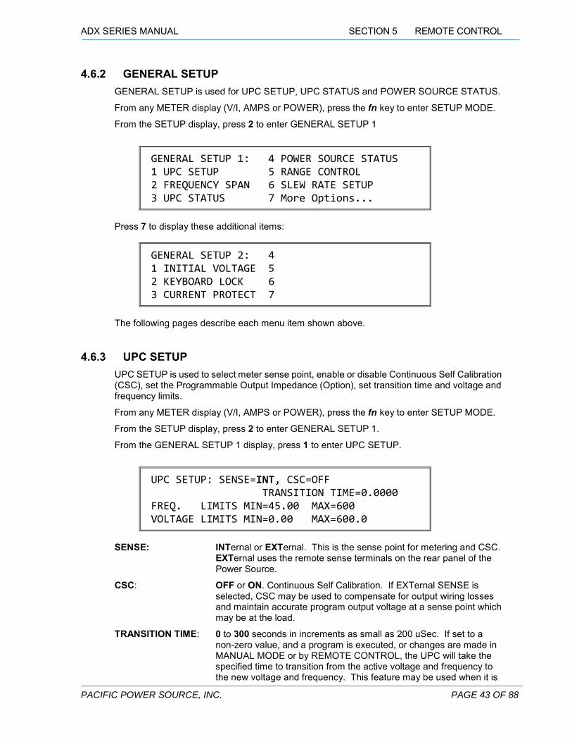
4.6.2 GENERAL SETUP GENERAL SETUP is used for UPC SETUP, UPC STATUS and POWER SOURCE STATUS.
From any METER display (V/I, AMPS or POWER), press the fn key to enter SETUP MODE.
From the SETUP display, press 2 to enter GENERAL SETUP 1
GENERAL SETUP 1: 4 POWER SOURCE STATUS 1 UPC SETUP 5 RANGE CONTROL 2 FREQUENCY SPAN 6 SLEW RATE SETUP 3 UPC STATUS 7 More Options...
Press 7 to display these additional items:
GENERAL SETUP 2: 4 1 INITIAL VOLTAGE 5 2 KEYBOARD LOCK 6 3 CURRENT PROTECT 7
The following pages describe each menu item shown above.
4.6.3 UPC SETUP UPC SETUP is used to select meter sense point, enable or disable Continuous Self Calibration (CSC), set the Programmable Output Impedance (Option), set transition time and voltage and frequency limits.
From any METER display (V/I, AMPS or POWER), press the fn key to enter SETUP MODE.
From the SETUP display, press 2 to enter GENERAL SETUP 1.
From the GENERAL SETUP 1 display, press 1 to enter UPC SETUP.
UPC SETUP: SENSE=INT, CSC=OFF TRANSITION TIME=0.0000 FREQ. LIMITS MIN=45.00 MAX=600 VOLTAGE LIMITS MIN=0.00 MAX=600.0
SENSE: INTernal or EXTernal. This is the sense point for metering and CSC.
EXTernal uses the remote sense terminals on the rear panel of the Power Source.
CSC: OFF or ON. Continuous Self Calibration. If EXTernal SENSE is selected, CSC may be used to compensate for output wiring losses and maintain accurate program output voltage at a sense point which may be at the load.
TRANSITION TIME: 0 to 300 seconds in increments as small as 200 uSec. If set to a non-zero value, and a program is executed, or changes are made in MANUAL MODE or by REMOTE CONTROL, the UPC will take the specified time to transition from the active voltage and frequency to the new voltage and frequency. This feature may be used when it is

ADX SERIES MANUAL SECTION 4 OPERATION
PACIFIC POWER SOURCE, INC. PAGE 44 OF 88
undesirable to cause abrupt changes to the output power signal. Transition Time does not affect transient operation.
FREQ LIMITS: 15.00 to 600 - Sets the MINimum and MAXimum programmable frequency limits of the UPC. The default MINimum is set to 45 Hz. for safe operation with output transformers. Before attempting to use very low frequencies with any magnetics, be aware of Volt-Second limitations.
VOLTAGE LIMITS: Sets the MINimum and MAXimum allowable voltage range. This is useful for protecting delicate loads. The voltage range is 0-150 Vac when the output is Direct Coupled and 0-(150 x XFMR Ratio) when XFMR Coupled.
4.6.4 FREQUENCY SPAN FREQUENCY SPAN sets the available frequency range and resolution of the output waveform and the number of samples per cycle used for metering data and harmonic analysis.
The FREQUENCY SPAN menu is accessed from the General Setup menu (fn,2,2).
FREQUENCY : PRESS 1 FOR 150 Hz SPAN=600Hz 2 FOR 300 Hz 3 FOR 600 Hz
PRESS FREQUENCY SPAN WAVEFORM STEPS METERING SAMPLES
1 15.00 – 150 Hz. 1024 512 2 15.00 – 300 Hz. 512 256 3 (default) 15.00 – 600 Hz. 256 128
4.6.5 UPC STATUS UPC STATUS indicates firmware part-number and version, SERIAL or GPIB interface status, and other system settings such as GPIB device address. The UPC SETUP menu is accessed from the General Setup menu (fn,2,1). The firmware part-number will vary depending on the model.
The UPC STATUS menu is accessed from the General Setup menu (fn,2,3).
If your UPC is configured with a serial port interface the UPC STATUS screen is:
UPC STATUS: FIRMWARE 141690 v5.25 BAUD:19200 PARITY:NONE LAST BYTE=00h TRANSFORMER RATIO 0.00 PAs=2 AMPS:VOLTS RATIO 5.00A=1 V SEC EOS=CR/LF

ADX SERIES MANUAL SECTION 5 REMOTE CONTROL
PACIFIC POWER SOURCE, INC. PAGE 45 OF 88
For systems equipped with a GPIB (IEEE-488) communication port, the display will be:
UPC STATUS: FIRMWARE 141690 v5.25 GPIB ADDRESS 1 IFC LAST DATA BYTE=00h TRANSFORMER RATIO 0.00 PAs=2 AMPS:VOLTS RATIO 5.00A=1 V SEC
For systems equipped with a manual controller (UPC-1M), the display will be:
UPC STATUS: FIRMWARE 141690 v5.25 TRANSFORMER RATIO 0.00 PAs=2 AMPS:VOLTS RATIO 5.00A=1 V SEC
To change any of these settings, press ENTER to move the cursor to each data field. Press EDIT when the cursor is positioned on the value to be changed. Type the new value, then press ENTER to continue editing or STORE to save and exit.
BAUD: 300, 1200, 2400, 4800, 9600, 19200, 38400. This is the serial port baud rate. The factory default value is 19200.
PARITY: NONE, ODD or EVEN. The default serial port parity value is NONE.
LAST BYTE= This field indicates the last data byte (DAB) received by the remote interface. The byte is shown in hexadecimal format. Hex 0D (Carriage Return) is displayed as Hex 0A (New Line). This is used for troubleshooting the remote interface.
GPIB ADDRESS: 0 to 30. This is the IEEE-488 device address for the UPC. The factory default address is 1.
IFC: “Interface Clear”. This is displayed only if an IEEE-488 Interface Clear message is received while this status display is shown. This display latches the IFC message. Press CLEAR to clear this display and the IFC field. It is used for troubleshooting the GPIB interface.
LAST DATA BYTE= Same as LAST BYTE=, above.
TRANSFORMER RATIO: Output Transformer Ratio: The value MUST match the ratio of the output transformer presently installed (3.7.1).
PAs= 2. This is the number of power amplifiers in the Power Source.
AMPS:VOLTS RATIO This sets the ratio of current to voltage for the UPC metering signals (3.7.2).
PRI/SEC: PRImary or SECondary. This is the current transformer location relative to an output transformer. To change this value, move the cursor to the field and press the +/- key (3.7.3).
EOS: CR/LF, LF or CR. The factory default Serial port End-Of-String character(s) value is CR/LF. Use the +/- key to select this value.

ADX SERIES MANUAL SECTION 4 OPERATION
PACIFIC POWER SOURCE, INC. PAGE 46 OF 88
4.6.6 POWER SOURCE STATUS POWER SOURCE STATUS indicates the state of internal control signals between the UPC and the Power Source circuits. See (2.3.4) OUTPUT CONTROL and (2.3.5) INPUT CONTROL for a description of these signals. This display is only used for technical diagnostics.
The POWER SOURCE STATUS menu is accessed from the General Setup menu (fn,2,4).
POWER SOURCE STATUS: 3PH 1PH CONNECTOR XFMR CMD FALSE TRUE TRUE FALSE CONF FALSE FALSE TRUE FALSE
CMD: Are Command signals sent from the UPC to the Power Source.
CONF: Are Confirmation signals sent from the Power Source to the UPC.
Pressing the +/- key toggles the Connector CMD signal state.
4.6.7 SLEW RATE SETUP
SLEW RATE SETUP allows the arrow key (︿ or ﹀) functions to transition at a predetermined rate. The SLEW RATE SETUP menu is accessed from the General Setup menu (fn,2,6).
SLEW RATE SETUP: VOLTS / SEC. = 1.00 HERTZ / SEC. = 1.00
Default values are 1 volt/second and 1.00 Hz./second.
Press EXECUTE to save the parameter entries.
NOTE: Slew rates are approximate.

ADX SERIES MANUAL SECTION 5 REMOTE CONTROL
PACIFIC POWER SOURCE, INC. PAGE 47 OF 88
4.6.8 INITIAL VOLTAGE INITIAL VOLTAGE SETUP allows you to specify the initial power up output voltage amplitude. The INITIAL VOLTAGE SETUP menu is accessed from the General Setup menu (fn,2,7,1).
INITIAL VOLTAGE SETUP: VOLTAGE=0 (Press +/- Key to Toggle Selection (Press ENTER or EXECUTE to Exit
VOLTAGE=: 0 or LAST EXECUTED. If 0 is chosen, the unit will set the output voltage to 0
regardless of output voltage prior to turning the unit off. Choosing LAST EXECUTED means the power source will automatically power on with the output voltage setting that existed prior to turning the unit off. The output relay will always be open at power-up unless an “Auto-Start” option has been installed.
NOTE: The default factory setting for INITIAL VOLTAGE is 0.
4.6.9 KEYBOARD LOCK KEYBOARD LOCK SETUP allows you to control the keyboard lock feature.
The KEYBOARD LOCK SETUP menu is accessed from the General Setup menu (fn,2,7,2).
KEYBOARD LOCK SETUP: LOCK=OFF (Press +/- Key to Toggle Selection (Press ENTER or EXECUTE to Exit
LOCK=: OFF or ON. If OFF is chosen, the keyboard is always enabled. If ON is
chosen, the keyboard is locked and disabled after pressing the DISPLAY key. Key presses are ignored when the keyboard is locked. The only exceptions are the CLEAR key and OUTPUT ENABLE key. To enable the keyboard, press the fn and EDIT keys at the same time. The keyboard remains enabled until you press the DISPLAY key.
NOTE: The default factory setting for KEYBOARD LOCK is off.

ADX SERIES MANUAL SECTION 4 OPERATION
PACIFIC POWER SOURCE, INC. PAGE 48 OF 88
4.7 INITIAL POWER-UP This paragraph describes the procedure used to power-on the ADX Power Source for the first time. The steps below are the recommended order of operation.
1. For new installations, check input connections (including proper input voltage). Do not
connect the load at this time. Also verify that the OUTPUT POWER switch is in the OFF position.
2. Switch the INPUT POWER switch to the ON position. The controller display will light up and begin to present output data.
3. Set the controller for the desired output voltage, frequency, etc.
4. Set the OUTPUT POWER switch of the ADX to the ON/AUTO position and press the UPC OUTPUT ENABLE switch to set it to the ON position.
CAUTION PRECAUTION
DO NOT CONNECT ANY LOADS TO THE OUTPUT OF THE POWER SOURCE UNTIL THE OUTPUT VOLTAGE AND FREQUENCY HAVE BEEN VERIFIED AS CORRECT.
APPLICATION OF IMPROPER VOLTAGE OR FREQUENCY CAN DAMAGE LOADS.
NE RACCORDER AUCUNE CHARGE SUR LA SORTIE DE L’EQUIPEMENT SANS AVOIR AU PREALABLE VERIFIE ET VALIDE LES PARAMETRES DE SORTIE TENSION ET FREQUENCE L’APPLICATION DE TENSION ET FREQUENCE INCORRECTES PEUT ENDOMMAGER LES CHARGES
CONNECTEES A L’EQUIPEMENT
5. Verify proper voltage, frequency and waveform at the output terminal block. If the output is
not correct, set the output to proper values.
6. When the desired output has been verified, turn the system OFF by first setting the OUTPUT POWER SWITCH to the OFF position and then opening the INPUT POWER SWITCH. Connect the load.
7. Re-start the unit beginning at step 2, above. Verify that the system delivers power to the load.
WARNING ATTENTION
LETHAL VOLTAGES ARE PRESENT AT THE INPUT AND OUTPUT TERMINALS OF THIS EQUIPMENT!
DES TENSIONS A CARACTERE MORTEL SONT PRESENTES SUR LES BORNES D’ENTRÉE ET DE SORTIE DE CET EQUIPEMENT!

ADX SERIES MANUAL SECTION 5 REMOTE CONTROL
PACIFIC POWER SOURCE, INC. PAGE 49 OF 88
4.8 ROUTINE POWER-UP After it has been verified that the installation is correct, follow the steps below for routine operation.
1. Set the OUTPUT POWER switch to the OFF position.
2. Switch the INPUT POWER switch to the ON position. The controller will light up and begin to display output data.
CAUTION PRECAUTION
DO NOT CONNECT ANY LOADS TO THE OUTPUT OF THE POWER SOURCE UNTIL THE OUTPUT VOLTAGE AND FREQUENCY HAVE BEEN VERIFIED AS CORRECT.
APPLICATION OF IMPROPER VOLTAGE OR FREQUENCY CAN DAMAGE LOADS.
NE RACCORDER AUCUNE CHARGE SUR LA SORTIE DE L’EQUIPEMENT SANS AVOIR AU PREALABLE VERIFIE ET VALIDE LES PARAMETRES DE SORTIE TENSION ET FREQUENCE L’APPLICATION DE TENSION ET FREQUENCE INCORRECTES PEUT ENDOMMAGER LES CHARGES
CONNECTEES A L’EQUIPEMENT
3. Set the OUTPUT POWER switch to the ON/AUTO position and press the UPC OUTPUT
ENABLE switch to set it to the ON position.
4.9 SYSTEM TURN-OFF The ADX Power Source is turned off by:
1. Set the OUTPUT POWER Switch to the OFF position.
2. Open the INPUT POWER circuit breaker.
4.10 SYSTEM SHUTDOWN This paragraph describes the conditions which will cause an automatic system shutdown and the procedure used to reset the ADX-Series Power Source.
WARNING ATTENTION
LETHAL VOLTAGES ARE PRESENT AT THE INPUT AND OUTPUT TERMINALS OF THIS EQUIPMENT!
DES TENSIONS A CARACTERE MORTEL SONT PRESENTES SUR LES BORNES D’ENTRÉE ET DE SORTIE DE CET EQUIPEMENT!

ADX SERIES MANUAL SECTION 4 OPERATION
PACIFIC POWER SOURCE, INC. PAGE 50 OF 88
4.10.1 SHUTDOWN CONDITIONS
The Output Contactor of the ADX-Series Power Source will be opened automatically when:
1. Excessive temperature is detected. Either the input power circuit or one of the power amplifiers has become too hot. Over-temperature is usually caused by either an overload on the system output or restricted air-flow (air inlets may be blocked, dirty fan filters, or a clogged or non-functioning fan).
2. The Output FORM (UPC controller) has been changed. While the Output Contactor is engaged, any change of FORM, low range to high range or high range to low range, will force the unit to open the output contactor so that the range can be changed safely.
When the Output Contactor has been opened due to one of the above faults, the red SHUTDOWN LED on the front panel of the power source will be lighted. The output contactor will remain open while the SHUTDOWN LED is lighted. This LED will remain lighted until the unit is reset.
If the Output Power Switch is in the ON/AUTO position when the unit is turned on, the SHUTDOWN LED will light. This is normal operation. The LED is turned off simply by placing the Output Power Switch into the OFF position.
4.10.2 RESETTING SHUTDOWN FAULTS A shutdown fault is reset as follows:
1. Set the OUTPUT POWER Switch to the OFF position. If the unit is controlled through the remote (GPIB or RS-232) port, command the output OFF (:OUTP OFF).
2. Wait for the SHUTDOWN LED to extinguish. This LED will remain lighted until the condition which caused the shutdown to occur has been corrected. In the case of shutdown due to over-temperature this may take some time while the unit cools. The output contactor cannot be engaged until the shutdown fault has been cleared.
3. After the SHUTDOWN LED has been extinguished, the unit will function normally.
NOTE: The SHUTDOWN LED is latched ON when a fault occurs. The OUTPUT POWER Switch or the Output Enable of the UPC MUST be placed in the OFF position before the SHUTDOWN LED will extinguish, even if the original fault no longer exists.
ADX SERIES MANUAL SECTION 5 REMOTE CONTROL
PACIFIC POWER SOURCE, INC. PAGE 51 OF 88
4.11 OUTPUT VOLTAGE FORMS The ADX is a dual-range power source. The output voltage range is selected by the FORM setting selected in the UPC controller. See the UPC Series Operation Manual for setup. The standard output configurations are:
FORM 1: 0 – 150 Vac
FORM 2: 0 – 300 Vac
A recommended strategy for selecting the optimum output voltage form is to select the minimum voltage range necessary to drive the load. That will provide the maximum available current and allows the power source to operate more efficiently. This results in less heat being created within the unit.
4.12 AUDIBLE ALERT An audible alert within the ADX will sound to indicate any of several conditions:
1) When power is applied, it will “beep” 2X indicating normal start-up.
2) If the AutoStart option has been ordered, the unit will “beep” several times indicating normal start-up and activation of the unit output. Power may be present at the output terminals immediately, depending on the active program settings. See the Modification insert if applicable to your unit for more information.
3) During operation a steady tone may be produced, indicating one of the following operational limits has been exceeded:
• Input AC voltage is too high or too low; not within the 90-264 Vac specification.
• Input current has exceeded 25 Arms. This could occur at low input voltage and high power output combination.
• Output power demand exceeds the specified 120% overload condition.

ADX SERIES MANUAL SECTION 4 OPERATION
PACIFIC POWER SOURCE, INC. PAGE 52 OF 88
4.13 CONSTANT CURRENT MODE The default mode of operation for the ADX is constant current mode. In this mode, the output voltage will be reduced once the set current limit is reached to maintain the current level drawn by the load. Once the load current demand drops below the set current limit level, the programmed output voltage is restored automatically. Thus, the AC Source continues to operate even if the UUT demands more current than the set current limit value. This current limit function is an average responding RMS current limit with a 50 msec response time. The current limit value can be set in the PROGRAM screen by entering the EDIT mode and using the ENTER key to scroll to the Ilim field value located at the bottom of this screen.
PROGRAM: #1 FROM=1 COUPLING=DIRECT FREQ=60.00 V=120.0 WF=1 #SEGS=0 Ilim=10.25
PROGRAM SCREEN Ilim SETTING NOTE: If the Ilim = value is set higher than the maximum available current for the range, the amplifier hardware limit will come in first so the Constant Current Mode does not engage.
CC Mode Specifications
Range: 0.1 – 50 Amps
Resolution: 0.05% of full scale
Accuracy: ±3% of full scale over the full range of ambient conditions
Table 4-1: CURRENT PROTECTION - CC MODE

ADX SERIES MANUAL SECTION 5 REMOTE CONTROL
PACIFIC POWER SOURCE, INC. PAGE 53 OF 88
4.14 CONSTANT VOLTAGE MODE (CURRENT PROTECTION MODE) When the CURRENT PROTECTION feature is enabled, the ADX will operate in a constant voltage mode. In this mode, if the load current exceeds the set current protection limit (IprA) for a specified period of time, the power source will generate a fault condition and open the output relay of the power source. This disconnects the load from the AC Source. An error message will be displayed on the screen when this event occurs. The programmable delay may be used to allow ride-through of temporary inrush current events and prevent nuisance tripping in this mode of operation. The protection delay (IprT=) can be set by the user in 100 msecs steps from 100msec (1) to 109.22 mins (65535) When the System Output is disabled due to Current Protect, the UPC will display
“ERROR – CURRENT PROTECTION TRIGGERED”
Either the CLEAR or DISPLAY button must be depressed to clear the fault before the OUTPUT ENABLE switch will operate.
To avoid conflicts with the constant current mode of operation, the protection mode has to be enabled by the user. It can be toggled ON or OFF from the CURRENT PROTECT MENU which is reached by pressing function key fn followed by:
Press 3 for GENERAL SETUP Press 7 for MORE OPTIONS… Press 3 for CURRENT PROTECT
(Sequence: fn 3 7 3)
CURRENT PROTECT SETUP: PROTECT=ON (Press +/- key to Toggle Selection) (Press ENTER or EXECUTE to Exit)
CURRENT PROTECTION MODE SETUP SCREEN To set the protection level and time delay for the constant voltage mode, the Ilim field in the PROGRAM screens can be toggled to the IprA and IprT fields by using the +/- toggle key. Once selected, use the ENTER key to proceed to the value field and use keypad to set Current Level and Delay in 100msec segments. Press EXECUTE to set the new values for the selected PROGRAM number.
PROGRAM: #1 FROM=1 COUPLING=DIRECT FREQ=60.00 V=120.0 WF=1 #SEGS=0 IprA=15.5
PROGRAM SCREEN IprA CURRENT LEVEL SETTING
+/- to Toggle field

ADX SERIES MANUAL SECTION 4 OPERATION
PACIFIC POWER SOURCE, INC. PAGE 54 OF 88
PROGRAM: #1 FROM=1 COUPLING=DIRECT FREQ=60.00 V=120.0 WF=1 #SEGS=0 IprT=1
PROGRAM SCREEN IprT TRIP DELAY SETTING CV Mode (CURRENT PROTECTION) Specifications
Level
Range: 0.1 – 50 Amps
Resolution: 0.05% of full scale
Accuracy: ± 0.2% of full scale + Calibration Reference
Delay
Range: 1 – 65535 (0.1 sec – 109.22 mins)
Resolution: 100 msecs (1 count = 100 msecs)
Accuracy ± 100 msecs
Table 4-2: CURRENT PROTECTION - CV MODE
Notes: 1. During system operation, the UPC must be metering system output for Current Protect to
operate. Current Protect (as with voltage and current metering) is disabled during program edit or UPC Setup mode for firmware revisions 5.2.2 or lower.
2. When the System Output is disabled due to Current Protect, the UPC will display, “ERROR – CURRENT PROTECTION TRIGGERED”. Either the CLEAR or DISPLAY button must be depressed to clear the fault before the UPC32 OUTPUT ENABLE switch will operate.
3. It is recommended the Current Limit (Ilim) be set to a value greater than Current Protect (IprA). Setting current limit at or below current protect value will prevent Current Protect from disabling the power source output.

ADX SERIES MANUAL SECTION 5 REMOTE CONTROL
PACIFIC POWER SOURCE, INC. PAGE 55 OF 88
4.15 POWER PROTECTION MODE All ADX models are furnished with an over power protection mode. If for whatever reason the ADX source is delivering considerably more true power than its maximum rating, the unit will shut down to protect itself from damage. Trip levels are typically set at 130% of rating and a two second delay is imposed to avoid nuisance tripping during temporary overloads or power inrush conditions. If the total output power drawn by the load exceeds the power trip level in Watts, the output is turned off and the following error message will be displayed:
ERROR – POWER PROTECTION TRIGGERED P= 2500W OUTPUT NOW DISABLED
The power protection trip level differs for each ADX model as shown in the table below. MODEL OPP TRIP LEVEL 110ADX 1300 W 115ADX 1950 W
Table 4-3: POWER PROTECTION TRIP LEVELS BY MODEL
Upon a triggering an over power fault, the ADX can be cleared by pressing the CLEAR button and the output can be re-enabled using the OUTPUT ENABLE button.

PACIFIC POWER SOURCE, INC. PAGE 56 OF 88
SECTION 5
REMOTE CONTROL OPERATION
5 REMOTE CONTROL OPERATION This section describes remote control functions of the ADX UPC controller for communication over the IEEE-488 BUS or Serial Remote Interface. To select the proper commands for accurate setup and control of the UPC/power-source system, a thorough understanding of the UPC capabilities is needed. It is strongly recommended that the user read (4.0) (Front Panel Operation) to become familiar with the features and capabilities of the UPC.
Most commands listed in this section are also used with both the Serial and optional GPIB Remote Interface.
5.1 PREFACE For GPIB communications, REMOTE CONTROL is established when control or programming commands are sent to the ADX controller by a Bus Controller with REN (remote enable) set true. The REN line on the bus interface must be held TRUE to maintain REMOTE CONTROL. REMOTE CONTROL can only be initiated and maintained while the UPC is displaying a Metering display or while in the UPC STATUS display, but not while manually editing any screen data. All front panel programming and signal controls are disabled while REMOTE CONTROL is active, but metering information is still accessible for viewing at the front panel display.
NOTE: Status and metered data queries do not place the UPC into REMOTE CONTROL.
The front panel LOCAL key allows the user to restore LOCAL CONTROL unless the Bus controller has sent the IEEE-488 - LOCAL LOCKOUT (LLO) message. The Bus Controller may restore LOCAL CONTROL by sending the IEEE-488 - GOTO LOCAL (GTL) message.
NOTE: Pacific Power Source has Instrument drivers available for use with National Instruments LabWindows, and LabView programming environments. These software drivers simplify programming and control of the ADX power source via the REMOTE interface. A sample application, UPC Interactive, written in LabView, including the source code, is provided.

ADX SERIES MANUAL SECTION 5 REMOTE CONTROL
PACIFIC POWER SOURCE, INC. PAGE 57 OF 88
5.2 PROGRAMMING CONVENTIONS 1. COMMANDS are shown in the left hand column in BOLD, beginning with an asterisk ( * ) or
colon ( : ) text with NO underline.
2. Command DESCRIPTIONS appear in the right hand column.
3. SCPI is "Standard Commands for Programmable Instruments -1992". Refer to the SCPI 1992 standard for more information. The full standard publication is available from the IVI Foundation at http://www.ivifoundation.org/
4. Some SCPI keywords are optional, and are ignored by the device. Optional keywords are enclosed in [ ] brackets.
5. Lowercase letters of commands shown are also optional.
6. The SCPI 1992 standard requires uppercase text in all SCPI commands (start with : ), however, the UPC is not case sensitive and will accept commands sent in lower case. It is recommended that programming formats follow the SCPI standard.
7. All SCPI commands have query command counterparts unless noted. A query command consists of the command immediately appended with a question mark ( ? ). Values cannot be sent with a query. IEEE-488.2 commands do not have query counterparts unless explicitly shown with a question mark appended.
8. IEEE-488.2 commands start with an asterisk ( * ) and are not case sensitive.
9. All required Functional Elements for devices are implemented.
10. Refer to the ANSI/IEEE-488.1 1987 and ANSI/IEEE-488.2 1987 standards for more information.
11. All numerical values are ASCII encoded decimal strings consisting of 1 or more ASCII digits. 8 and 16 bit register values are binary weighted values represented by an ASCII string of 1 or more decimal digits. One exception, the Serial Poll byte, is an 8 bit hexadecimal byte.
12. Multiple Commands and Queries may be sent in one Program Message but each must be separated by a semicolon ( ; ). The term 'Program Message' refers to one or more commands and/or queries sent to the controller as one continuous string and is not to be confused with Stored Programs (1-99) within the controller.
13. Multiple data parameter names and values must be separated by commas.
14. Multiple keyword' messages may be sent without duplicating the first level SCPI keyword (i.e., SOURce). e.g., :SOURce:VOLTage1,120; FREQuency,60 A keyword is a single word beginning with a colon (:).
15. Program Messages MUST be terminated with a LINE FEED (0Ahex, 10dec) or END (EOI) signal. This is referred to as an end-of-string <eos>. A Carriage Return character (0Dhex, 13dec) is converted to a LINE FEED by the UPC. Further SCPI commands shall begin with a first level keyword (i.e.,:SOURce:).
16. All values shown in angle brackets <> are examples of real values used with commands but labels are sometimes used to indicate a variable which is not known until actual time of use. e.g., <AMPS meter range> might actually be <50>. Units such as AAC, Hz. or % shown after the angle bracketed value are not to be included inside the value, but are shown as a reference to the units. The angle brackets are not part of the value.
17. The controller data input buffer is 8k bytes, as is its data output buffer. No program message may exceed this length.
18. All :SOURce: commands also support query. An alternate method of writing or reading the
ADX SERIES MANUAL SECTION 6 MAINTENANCE
PACIFIC POWER SOURCE, INC. PAGE 58 OF 88
presently active :SOURce:FORM, COUPLing, VOLTage, FREQuency, and CURRent:LIMit values is to use PROGram 0 (see examples). PROGram 0 contains the MANUAL MODE parameters. NOTE: Sending any :SOURce: command invokes MANUAL MODE and REMOTE CONTROL.
19. Command strings may contain spaces.
20. The controller interface accepts IEEE-488.2 NR1, NR2 and NR3 numeric formats. Most query responses are NR1 or NR2 types. i.e., NR1=120, NR2=120.0, NR3=1.2E+02.
21. Follow any command (in the same Program Message) with *OPC (5.5.3.1) to detect completion of the command or termination of a Transient event. An SRQ occurs when the command or Transient is complete (if ESB bit is set in SRE and OPC bit is set in ESE). *OPC? may be used in the same manner.
5.3 PROGRAM CONTROL PROGram:NAME <nn> Command: selects program “nn” for executing, deleting or copying.
nn = <0> to <99>
Query: returns the program number last selected.
PROGram[:SELected]:DEFine <program>
Command: defines the values stored in program “nn”. Both steady-state and transient segment parameter names and values may be sent. Program parameters are defined in the following sections.
NOTE: Only commas may separate the values, NO Carriage Returns or Line Feeds may separate the values within a single Command.
Query: returns steady-state values of selected program and segment values of most recently selected segment or multiple segments if specified by a previous NSEGS parameter. "LAST" is returned with segment data if the segment is the last segment in the program.
STEADY-STATE OUTPUT PARAMETERS
FORM,<n>, COUPLing,<s>, FREQuency,<n>, VOLTage,<n>, (1 is implied and may be omitted). VOLTage1,<n>, (or not) CURRent:LIMit,<n>, EVENTS,<n>,

ADX SERIES MANUAL SECTION 5 REMOTE CONTROL
PACIFIC POWER SOURCE, INC. PAGE 59 OF 88
5.3.1 STEADY STATE OUTPUT PARAMETERS FORM,<n> sets Output Power Form of selected program.
n = <1>Single Ф, <2>Split Ф, or <3>Three Ф
COUPLing,<s> sets Output coupling of selected program. s = <DIRECT> or <XFMR>
XFMRRATIO,<n.nn> sets Output XFMR ratio (n.nn:1) of selected program. n.nn = <0.05> to <5.00>
FREQuency,<n> sets Output Frequency of selected program. n = <:SOUR:FREQ:LIM:MIN> to <:SOUR:FREQ:LIM:MAX> Hz.
VOLTage,<n> sets Output VOLTAGE ФA of selected program. n = <0> to <150, or 150 x XFMRRATIO> Volts
VOLTage1,<n> sets Output VOLTAGE ФA of selected program. n = <0> to <150, or 150 x XFMRRATIO> Volts
CURRent:LIMit, <n> sets Output Current Limit of selected program. n = <0> to <AMPS meter range> Amps
NOTE: The value will revert back to 1 after each query.
Query: The NSEGS parameter of a :PROG:DEF? query on any ADX is always zero.
5.3.2 PROGRAM MEMORY CONTROL :PROGram:[SELected:]DELete Command: (No query) deletes selected program.
Attempting to DELete an EXECuting Program will report an Error.
:PROGram:DELete:ALL Command: (No query) deletes all programs, calibration data
and setup values. Performs device RESET, loads Program #1 with *RST default values (5.6.2), executes MANUAL MODE with *RST values. Attempting to DELete an EXECuting Program will report an Error. NOTE: Calibration values are deleted.
:PROGram:COPY <dest> Command: (No query) copies the selected program
(previously specified by :PROG:NAME <nn>) to <dest>. <dest> = 1 thru 99 NOTE: that the destination Program cannot be currently EXECuting.

ADX SERIES MANUAL SECTION 6 MAINTENANCE
PACIFIC POWER SOURCE, INC. PAGE 60 OF 88
5.4 SOURCE CONTROL
5.4.1 OUTPUT PROGRAMMING :PROGram:EXECute Command: executes selected Program steady-state values.
Selected program is specified by previous PROGram:NAME <nn> command. Query: returns the number of the currently executing program. If no program is executing, query returns -1.
:[SOURce:]VOLTage <n> sets Output VOLTAGE amplitude of all available Phases. n = <0> to <150, or 150 x XFMRRATIO> Volts
:[SOURce:]VOLTage1 <n> sets Output VOLTAGE ФA. n = <0> to <150, or 150 x XFMRRATIO> Volts
:[SOURce:]FREQuency <n> sets Output Frequency. n = <:SOUR:FREQ:LIM:MIN> to <:SOUR:FREQ:LIM:MAX> Hz. Query: Returns the programmed frequency value. For metered frequency, see :MEASure:FREQuency? (Page 86).
:[SOURce:]CURRent:LIMit <n> sets Output Current Limit. n = <0> to <Current meter range> RMS Amps
:[SOURce:]CURRent:LIMit:MAX? <n> query returns the maximum current limit allowed based on the present Form, Coupling and current transformer.
:[SOURce:]RAMP <t> sets Output TRANSITION TIME of voltage and frequency execution. t = <0> to <300> seconds in increments as small as .0002 Sec
:[SOURce:]FREQuency:SPAN <n> sets Output Frequency Span. n = <150>, <300>, <600> Hz. After sending, allow 8 seconds for UPC restart before sending any additional command or query. This setting changes the resolution of the output signal, metering and Harmonic Analysis option (2.1.1) and (4.3.1.1).
:[SOURce:]FREQuency:LIMit:MAXimum <n> sets Output Frequency max limit. n = <15.00> to <600> Hz., depending on Frequency Span
:[SOURce:]FREQuency:LIMit:MINimum <n> sets Output Frequency min limit. n = <15.00> to <600> Hz., depending on Frequency Span
:[SOURce:]FREQuency:LIMit:RANGe? <min,max> Query: Returns the minimum and maximum allowable frequency limits.
:[SOURce:]VOLTage:LIMit:MAXimum <n> sets Output Voltage max limit. n = <0.00> to <300> VAC RMS, must be greater than MIN
:[SOURce:]VOLTage:LIMit:MINimum <n> sets Output Voltage min limit. n = <0.00> to <600> VAC RMS, must be less than MAX
:[SOURce:]VOLTage:LIMit:RANGe? <min,max> query only. Returns the minimum and maximum allowable voltage limit.
:[SOURce:]VOLTage:INITial <b> sets initial output voltage at power up. b = <0> (0 volts) or <1> (last executed)
:[SOURce:]RANGe <n> sets Output Range Control (for power sources with Range

ADX SERIES MANUAL SECTION 5 REMOTE CONTROL
PACIFIC POWER SOURCE, INC. PAGE 61 OF 88
Control). n = <0> to <4>. 0 sets Range Control to AUTO
:OUTPut[:STATE] <b> Command: OUTPUT ENABLE. Opens or Closes the power source output relay. b = <OFF> or <0>, <ON> or <1>.
Query: returns actual state of output relays, <0>OFF or <1>ON, not the OUTPUT ENABLE value
NOTE: Setting the OUTPUT POWER ON-AUTO/OFF switch (front panel of the power source) to OFF, overrides the OUTPUT ENABLE command.
5.4.2 CONFIGURATION :[SOURce:]FORM <n> Sets Output power form.
n = <1>Single Ф, <2>Split Ф, or <3>Three Ф
:[SOURce:]COUPLing <s> Sets Output coupling. s = <DIRECT> or <XFMR>
:SENSe:PATH <s> Selects source location for metering and CSC. s = <0>Internal or <1>External

ADX SERIES MANUAL SECTION 6 MAINTENANCE
PACIFIC POWER SOURCE, INC. PAGE 62 OF 88
5.5 QUERY FUNCTIONS The following are 'query only' functions sent to the UPC through the communication bus
5.5.1 CONFIGURATION QUERIES These query parameters cannot be set via the remote communication port. The values of each are specific to the hardware configuration of the individual power source.
:[SOURce]:XFMRRATIO? Query: Output XFMR ratio. Returns <0.05> to <5.00>.
:[SOURce]:AVR? Query: Current transformer AMPS:VOLTS ratio. Returns <1> to <500>
:[SOURce]:CTLOC? Query: Current transformer location. Returns <1> (PRIMARY) or <0> (SECONDARY).
:[SOURce]:AMPLIFIERS? Query: Number of installed power amplifiers in Power Source
:SENSe:CURRent:RANGe? Query: AMPS meter range. Returns <0> to <AMPS meter range> RMS Amps
5.5.2 MEASUREMENT QUERIES Measurement occurs once per :MEASure: command. AC measurements are assumed.
• The SCPI :AC keyword following :MEASure is optional and is not shown here. • The “?” is optional, :MEASure: implies a query. Values following a command are ignored • 'Multiple keyword' queries may be performed to obtain values of simultaneous
measurements. e.g., :MEASure:VOLTage1;VOLTage2;VOLTage3?
:MEASure:VOLTage1? Query: metered voltage ФA. Returns <0> to <354> VAC RMS
:MEASure:VLL1? Query: metered Line to Line voltage ФA - ФB. Returns <0> to <354> VAC RMS
:MEASure:FREQuency? Query: Metered frequency value. Returns <15.00> to <600> Hz.
:MEASure:CURRent[:RMS]1? Query: metered RMS current ФA. Returns <0> to <current meter range> AAC RMS
:MEASure:CURRent:PEAK1? Query: metered peak current ФA. Returns <0> to <current meter range> AAC Peak
:MEASure:CURRent:CREST1? Query: metered current Crest Factor ФA. Returns <0> to <1000>
:MEASure:POWer1? Query: metered Kilowatts ФA. Returns <0> to <1000> KW
:MEASure:KVA1? Query: metered KiloVoltAmps ФA. Returns <0> to <1000> KVA
:MEASure:PF1? Query: metered power factor (KW/KVA) ФA. Returns <0> to <1.0>

ADX SERIES MANUAL SECTION 5 REMOTE CONTROL
PACIFIC POWER SOURCE, INC. PAGE 63 OF 88
5.5.3 EVENT AND STATUS REPORTING Events and device Status may be queried by the Bus Controller through the following registers and queues. Query commands are explicitly shown in this section for clarity.
NOTE: It is recommended that reading EVENT and STATUS registers and queues occur in the following order. Reading any register or queue is optional. Indents indicate a hierarchy.
1. STB register, read via Serial Poll or *STB?.
2. ESR register, read via *ESR?.
3. SYSTem:ERRor? queue.
4. STATus:OPERation:EVENt? register.
5. STATus:QUEStionable:EVENt? register.
NOTE: For most applications, the STB register and SYSTem:ERRor queue will satisfy status and error reporting.
5.5.3.1 IEEE488.2 STATUS REPORTING Both IEEE-488 and serial port communications with UPC support the status reporting standards. Query commands are explicitly shown for clarity. Refer to the ANSI/IEEE-488.2 1987 standard for more information.
NOTE: <NRf> indicates Numeric Response format.
STATUS BYTE REGISTER (STB)
STATUS conditions reported by the STATUS BYTE may be queried via the IEEE-488 Bus Serial Poll function, or read directly using *STB?. The SRQ function will be invoked to signal the Bus controller that service is requested, when an unmasked STATUS BYTE bit goes true. Note that no SRQ is generated while in LOCAL CONTROL. *CLS clears the ESR and the STB (Figure 5.1).
The IEEE-488.2 Common Commands for Status Reporting from the UPC are:
BIT NAME DEFINITION 7 SOS :STATus:OPERation register bit summary 6 MSS/RQS - MASTER SUMMARY
summarizes all STATUS BYTE bits (except bit 6) for *STB?, or, - REQUEST SERVICE indicates the device requested service when Serial Poll was performed.
5 ESB STANDARD EVENT STATUS REGISTER bit summary 4 MAV MESSAGE AVAILABLE indicates Query response data is available 3 SQS :STATus:QUEStionable register bit summary 2 EEQ ERROR/EVENT QUEUE indicates an SCPI Error/Event message is
available 1 BUSY indicates UPC front panel not in V/I mode 0 SHUTDOWN indicates Power Source SHUTDOWN
Table 5-1: IEEE-488.2 STATUS BITS
Setting a SERVICE REQUEST ENABLE (SRE) bit true unmasks the STATUS bit in the STB. Bit 6 of the SRE is not applicable as the MASTER SUMMARY bit of the STB cannot be masked. The STB, SRE, ESR and ESE registers are 8 bits each.

ADX SERIES MANUAL SECTION 6 MAINTENANCE
PACIFIC POWER SOURCE, INC. PAGE 64 OF 88
&
7 5
&
&
SOS ESB
6
RQS
MSS
7 ESB
*SRE <NRf>
34
&
&
2
&
*SRE?
&
1 0
SQS
3MAV
EEQ
2 1 0
Figure 5-1: STATUS BYTE MODEL

ADX SERIES MANUAL SECTION 5 REMOTE CONTROL
PACIFIC POWER SOURCE, INC. PAGE 65 OF 88
STANDARD EVENT STATUS REGISTER (ESR)
Events reported by the STANDARD EVENT STATUS register may be queried via the *ESR? command. Reading the ESR register clears it. The EVENT STATUS summary bit in the STATUS BYTE (STB) will be set when an unmasked EVENT STATUS bit goes true.
BIT NAME DEFINITION 7 PON POWER ON indicates Input power was just applied 6 URQ USER REQUEST indicates "LOCAL" key was just pressed 5 CME COMMAND ERROR indicates invalid command or query received 4 EXE EXECUTION ERROR indicates can't execute command with data
received 3 DDE DEVICE DEPENDANT ERROR indicates UPC not properly configured 2 QYE QUERY ERROR indicates cannot respond with data 1 RQC REQUEST CONTROL - not used 0 OPC OPERATION COMPLETE indicates previous operation complete
Table 5-2: STANDARD EVENTS STATUS REGISTER (ESR) BITS
Setting an EVENT STATUS ENABLE (ESE) bit true unmasks the EVENT bit in the ESR. Also see :SYSTem:ERRor? query for corresponding information.
5.5.4 SCPI STATUS REPORTING The following lists the SCPI Commands for Status Reporting from the UPC. Refer to the SCPI 1992 standard for more information. Query commands are explicitly shown in this section for clarity (Figure 5-2). See (5.2) Conventions regarding SCPI.
:SYSTem:ERRor? Query: system error
Returns one of the following types of messages, with details appended to it if possible. A maximum of 256 characters may be sent as a response to this query.
-0, "No error" No error detected
-100, "Command error" indicates invalid command or query received
-200, "Execution error" indicates can't execute command with parameters received
-300, "Device-specific error" indicates UPC not properly configured
-400, "Query error" indicates query aborted
NOTE: The SYSTem:ERRor query clears the corresponding error bit in the ESR.
:SYSTem:VERSion? Query: SCPI version. Returns <1992.0>.
:SYSTem:SERIALNUMber? Query: Returns serial number string (1-15 characters). Note: The serial number is also displayed on the LCD display at power up.

ADX SERIES MANUAL SECTION 6 MAINTENANCE
PACIFIC POWER SOURCE, INC. PAGE 66 OF 88
The STATus:OPERation and STATus:QUEStionable registers provide information about the present mode of operation.
• Transition of a CONDition bit to the true state causes the EVENt bit to be set true. • Unmasked ENABle bits allow an EVENt bit to be reported in the summary bit for that
EVENt register in the STATUS BYTE register. • Setting an ENABLe bit true unmasks the corresponding EVENt bit. • Reading an EVENt register clears it. • All :STATUS registers are 16 bits.
The STATus:OPERation registers provide information about the present mode of operation.
NOTE: Most bits in the following :STATus registers are not applicable to the UPC but are shown for reference and may be used for future product enhancements. The PROGram running bit (14) in the :STATus:OPERation registers indicates a stored program (PROGRAM# 1-99) is running.
:STATus:OPERation:CONDition? present condition query.
:STATus:OPERation:ENABle enables events to be reported in the SOS bit in the STB.
:STATus:OPERation:ENABle? STAT:OPER:ENABLE register query.
:STATus:OPERation:EVENt? latched condition query. The STATUS:QUESTIONABLE registers provide information about errors and questionable measurements.
NOTE: All bits in the following :STATus registers are not applicable to the UPC but are shown for reference and may be used for future product enhancements.
:STATus:QUEStionable:CONDition? present condition query.
:STATus:QUEStionable:ENABle enables events to be reported in the SQS bit in the STB.
:STATus:QUEStionable:ENABle? STAT:OPER:ENABLE register query.
:STATus:QUEStionable:EVENt? latched condition query.

ADX SERIES MANUAL SECTION 5 REMOTE CONTROL
PACIFIC POWER SOURCE, INC. PAGE 67 OF 88
Figure 5-2: SCPI STATUS REGISTERS MODEL

ADX SERIES MANUAL SECTION 6 MAINTENANCE
PACIFIC POWER SOURCE, INC. PAGE 68 OF 88
5.6 DEVICE CONTROL :SYSTem:BEEPer Command: sounds the front panel beeper once. No
query.
:SYSTem:KLOCK <b> Command: sets the keyboard lock enable state (4.6.3.8). b = .<1> enables keyboard lock; <0> disables keyboard lock. Query: returns present lock enable state.
:CALibrate:ZERO Command: resets all Metering correction factors. No query. ADX controller meters are then uncalibrated although still functional. See Externally Referenced Calibration (7.3) for details.
:CALibrate:DATA <meter_int_Va, meter_int_Vb, meter_int_Vc, meter_ext_Va, meter_ext_Vb, meter_ext_Vc, meter_Ia, meter_Ib, meter_Ic>
Command: loads values measured with an external DVM and Ammeter for calibration of UPC metering. No query
• The first 3 values are Voltages measured at the output relay of the power source.
• The second set of 3 values are Voltages measured at the EXTernal Sense point (at the load).
• The third set of 3 values are Currents measured to the load.
NOTE: If FORM=1 is currently selected, meter_Ia is the Phase 1 current. Loading a value of 0 will cause that metering parameter to be uncalibrated although it will still be functional. See Externally Referenced CALIBRATION (8.2) for more details.
:CALibrate:KFACTORS <k_int_Va, k_int_Vb, k_int_Vc, k_ext_Va, k_ext_Vb, k_ext_Vc, k_Ia, k_Ib, k_Ic k_oscA, k_oscB, k_oscC >
Command: directly loads calibration factors for UPC metering. The first 3 values are Voltage kFactors for the INTernal sense metering of the power source. The second set of 3 values are Voltage kFactors for the EXTernal Sense point (at the load). The third set of 3 values are current (amperes) kFactors The fourth set of 3 values are the oscillator gain kFactors

ADX SERIES MANUAL SECTION 5 REMOTE CONTROL
PACIFIC POWER SOURCE, INC. PAGE 69 OF 88
NOTE: The values apply only to the presently set output FORM. If FORM=1 is currently selected, k_Ia is the Phase 1 Current kFactor. Refer to (8.2.1) for more information about kFactors.
Query: Returns the presently stored kFactors.
:CALibrate:KFACTORS:ALL <k_int_V1, NAN, NAN, k_ext_V1, NAN, NAN, k_I1, NAN, NAN, k_osc1, NAN, NAN, k_int_V2, NAN, NAN, k_ext_V2, NAN, NAN, k_I2, NAN, NAN, k_osc2, NAN, NAN, k_int_Va, k_int_Vb, k_int_Vc, k_ext_Va, k_ext_Vb, k_ext_Vc, k_Ia, k_Ib, k_Ic,k_oscA, k_oscB, k_oscC >
Query: Returns all kFactors without having to specify the Form
5.6.1 IEEE-488.1 INTERFACE FUNCTIONS The following lists the IEEE-488.1 capabilities of the UPC. Refer to the ANSI/IEEE-488.1 1987 standard for more information.
FUNCTION MNEMONIC REMOTE MESSAGE RECEIVED / Description
SH1 Source handshake functions AH1 Acceptor handshake functions T6 MTAnn - Talker subset 6. nn is GPIB device address 0-30 L3 MLAnn - Listener subset 3. nn is GPIB device address 0-30
SR1 Service request/Serial Poll functions SPE - Serial Poll Enable SPD - Serial Poll Disable
RL1 Local/Remote functions GTL - Go To Local LLO - Local Lockout
DC1 Device clear functions DCL - causes a hardware RESET of the UPC SDC - Same as DCL but device must be addressed
DT1 Device Trigger function GET - Group Execute Trigger message executes Transient Events (if any), of currently executed program
PP0 No Parallel Poll functions C0 No Controller functions E1 Electrical interface Type 1 IFC InterFace Clear (IFC) sets the UPC IEEE-488 bus interface to an
idle state. The data input and data output buffers remain unchanged
Table 5-3: IEEE-488.1 INTERFACE FUNCTIONS

ADX SERIES MANUAL SECTION 6 MAINTENANCE
PACIFIC POWER SOURCE, INC. PAGE 70 OF 88
5.6.2 IEEE 488.2 COMMON COMMANDS The following lists the IEEE-488.2 Common Commands for Device Control of the UPC. Refer to the ANSI/IEEE-488.2 1987 standard for more information.
*RST Command: RESET. Initialize the UPC with the following parameters:
CSC OFF CURRENT LIMIT CURRENT METERING RANGE INITIAL VOLTAGE 0 KEYBOARD LOCK OFF MAX FREQUENCY 600 Hz. MAX VOLTS 600 V MIN FREQUENCY 45 Hz. MIN VOLTS 0 V MODE MANUAL OUTPUT DISABLED OUTPUT COUPLING DIRECT OUTPUT FORM 1 OUTPUT FREQUENCY 60 Hz. OUTPUT VOLTAGE(S) 0 RANGE CONTROL AUTO SENSE INTERNAL TRANSITION TIME 0 WAVEFORM ФA 1
Table 5-4: RESET STATE SETTING VALUES
NOTE: Stored programs are not erased. FREQUENCY SPAN is not changed.
*TST? Query: Self test. Test validity of non-volatile RAM. Returns 0 if no error.
*WAI Command: Wait-to-continue. Only useful following the :PROG:EXEC:TRANS or *TRG commands. All other commands are executed sequentially as the Program Message is parsed.
*TRG Command: IEEE-488.2 Device trigger function. Executes Transient Events (if any), of currently executed program.
*LLO Command: LOCAL LOCKOUT. Puts the UPC into REMOTE mode and disables local operation of the UPC keyboard.
*GTL Command: GOTO LOCAL. Enables local operation of the UPC keyboard.
*DCL Command: DEVICE CLEAR. Performs a hardware RESET of the UPC.

ADX SERIES MANUAL SECTION 5 REMOTE CONTROL
PACIFIC POWER SOURCE, INC. PAGE 71 OF 88
5.7 REMOTE CONTROL EXAMPLES The REN (remote enable) line on the bus interface must be kept true to maintain REMOTE CONTROL. REMOTE CONTROL can only be initiated while the UPC is displaying a Metering display or while in the UPC STATUS display, not while editing.
See (3.5) for setting up the SERIAL INTERFACE parameters.
If the GPIB option is installed, be sure that the UPC GPIB device address is set to a known unique address within any GPIB system. The factory default device address is 1. See (4.6.5) for configuration of the GPIB device address.
Optional keywords have been omitted throughout this section for clarity. The command strings may contain spaces.
NOTE: Un-address means to send the UNTALK and UNLISTEN messages. This is only applicable for the GPIB, NOT the serial option. With many programming languages that support GPIB communications, listener and talker addressing and un-addressing is handled automatically and is transparent to the user. Check your programming language or driver documentation for verification.
NOTE: <eos> should be a LINE FEED (0Ahex, 10dec). See GPIB convention #15 (5.2) for more details.
CAUTION
ALL :SOURce PARAMETERS SHOULD BE SET PRIOR TO ENABLING THE OUTPUT FOR THE FIRST TIME
AFTER POWER-ON OR AFTER RESETTING THE UNIT.
THE PARAMETERS MAY BE SET INDIVIDUALLY OR BY USING :DEFine AND :EXECute OF A STORED PROGRAM
SEE PARA. 5.7.1, 5.7.3 AND 5.7.5

ADX SERIES MANUAL SECTION 6 MAINTENANCE
PACIFIC POWER SOURCE, INC. PAGE 72 OF 88
5.7.1 EXAMPLE OF STORING A PROGRAM Step A. Address the UPC as a listener.
:PROGram:NAME 1 <eos> Step B. Select Program 1.
NOTE: <eos> is a LINE FEED (0Ahex, 10dec).
:PROGram:DEFine? <eos> Step C. Define program 1. Program 1 consists of steady-state parameter names and values. This Query returns steady-state values of the selected program and segment values of the most recently selected segment (see NOTE 1). "LAST" is returned with segment data if the segment is the last segment in the program.
Step D. Address the UPC as talker, read back the response string.
NOTE: Only commas separate the values, NO Carriage Returns or Line Feeds separate the values as received.
STEADY-STATE OUTPUT PARAMETERS returned FORM,3, COUPLing,DIRECT, XFMRRATIO,1.0, FREQuency,60, VOLTage1,115, VOLTage2,115, VOLTage3,115, CURRent:LIMit,10 PHASe2,120, PHASe3,240, WAVEFORM1,1, WAVEFORM2,1, WAVEFORM3,1, EVENTS,0, NSEGS,0,
Step E. Un-address UPC.
5.7.2 EXAMPLE OF EXECUTING A STORED PROGRAM Step A. Address the UPC as a listener.
:PROGram:NAME 1 <eos> Step B. Select Program 1.
NOTE: <eos> is a LINE FEED (0Ahex, 10dec)
:PROGram:EXECute <eos> Step C. Execute Program.
Step D. Un-address UPC.

ADX SERIES MANUAL SECTION 5 REMOTE CONTROL
PACIFIC POWER SOURCE, INC. PAGE 73 OF 88
5.7.3 EXAMPLE OF DIRECTLY CHANGING THE OUTPUT PARAMETERS Change Frequency and Volts for all phases then ENABLEs the OUTPUT.
Step A. Address the UPC as a listener.
:FREQuency 50 <eos> Step B. Change Frequency to 50 Hz.
:VOLTage 117 <eos> Step C. Change Volts to 117 VAC RMS for all phases.
:OUTPut ON <eos> Step D. ENABLES the OUTPUT.
The OUTPUT POWER switch must be in the ON/AUTO position to allow power to be applied to the load.
Step E. Un-address UPC.
An alternative to steps B, C and D above is:
:FREQ 50; :VOLT 117; :OUT ON<eos> This example uses all short form keywords in one Program Message. The OUTPUT POWER switch must be in the ON/AUTO position to allow power to be applied to the load.
- or -
:OUTPut OFF <eos> Turns the output OFF.
5.7.4 EXAMPLE OF VOLTAGE and CURRENT MEASUREMENT QUERY How to query the UPC for three phase RMS volts (Line to Neutral) and RMS current metered values.
LINE to LINE volts, KVA, KW, Power Factor, CURRENT Crest Factor, and Peak Current may also be queried in the same way.
See the :FETCH command and example for obtaining metered waveform data.
Step A. Address the UPC as a listener.
Step B. Select Voltages A,B,C and Load Current A,B,C for AC-RMS query by sending the following command.
:MEAS:VOLT1;VOLT2;VOLT3;CURR1;CURR2;CURR3? <eos>
NOTE: <eos> is a LINE FEED (0Ahex, 10dec).
All parameters will be measured simultaneously upon receipt of the :MEAS: command. This may take several hundred milliseconds depending upon Frequency and other factors. The values are not stored in the UPC and another :MEAS: command will re-measure the values, further delaying response.
Step C. Address the UPC as a talker to read back a query response string, similar to the following example, representing the three voltages and currents.
120.2,120.3,121.0,3.2,2.9,3.0<eos>
Step D. Un-address UPC.

ADX SERIES MANUAL SECTION 6 MAINTENANCE
PACIFIC POWER SOURCE, INC. PAGE 74 OF 88
SECTION 6
MAINTENANCE
6 MAINTENANCE This section describes the maintenance of the ADX Power Source.
6.1 MAINTENANCE INTERVAL Maintenance is required once every six months and consists of performing regular calibration. Refer to Section 6 for details. For critical applications or if system operation is suspect or operating conditions are extreme the calibration interval may be shortened.
It is recommended to check/clean the air intake and exhaust areas and the fans when calibrating, or more often as required by operating conditions.

PACIFIC POWER SOURCE, INC. PAGE 75 OF 88
SECTION 7
CALIBRATION
7 CALIBRATION This section describes the calibration requirements of the ADX AC Power Source.
7.1 CALIBRATION INTERVAL The ADX Power Source requires calibration once every six months or after service has been performed to the system.
7.1.1 TEST EQUIPMENT REQUIREMENTS The test equipment listed below is required for calibration of the ADX-Series Power Source.
1. Digital Voltmeter: 4½ Digit True-RMS responding 5000 Hz bandwidth, minimum 2. Frequency counter: 5 digit counter, minimum 3. Digital Ammeter: 3½ Digit True-RMS responding 5000 Hz bandwidth, minimum
(Alternate: Current transformer used in conjunction with the DVM.)
4. Oscilloscope: (Optional but recommended) 5. Load (Resistive): 10 Amps at 150 VAC, 5 amps at 300 VAC

ADX SERIES MANUAL SECTION 7 CALIBRATION
PACIFIC POWER SOURCE, INC. PAGE 76 OF 88
7.2 CALIBRATION PROCEDURE This calibration procedure verifies that system gains for output and metering are set properly and that the system performance, relative to output power capability is intact. Gains in various signal paths within the controller are adjusted by the procedure of Paragraph 6.3.1. Output power capability of the power source is tested by the procedure of Paragraph 6.3.2.
WARNING ATTENTION
THIS EQUIPMENT CONTAINS HIGH ENERGY, LOW IMPEDANCE CIRCUITS!! LETHAL POTENTIALS ARE CONTAINED WITHIN THE CABINET.
CARE MUST BE EXERCISED WHEN SERVICING THIS EQUIPMENT IN ORDER TO PREVENT SERIOUS OPERATOR INJURY OR EQUIPMENT DAMAGE.
VOLTAGE AT THE TERMINALS RESPONDS INSTANTLY WHEN THE OUTPUT IS ACTIVATED.
OBSERVE THE FOLLOWING WHEN SERVICE, MAINTENANCE, OR CALIBRATION ARE REQUIRED:
1. REMOVE ALL JEWELRY FROM HANDS, ARMS AND NECK WHEN SERVICING THIS EQUIPMENT. THIS PREVENTS THE POSSIBILITY OF SHORTING THROUGH THE JEWELRY AND CAUSING BURNS OR ELECTROCUTION OF THE OPERATOR.
2. WEAR SAFETY GLASSES WHEN SERVICING THIS EQUIPMENT TO PREVENT EYE INJURY DUE TO FLYING PARTICLES CAUSED BY ACCIDENTAL SHORT CIRCUIT CONDITIONS.
3. DO NOT REMOVE ANY PANEL OR COVER WITHOUT FIRST REMOVING THE INPUT SERVICE BY OPENING ALL CIRCUIT BREAKERS.
4. SERVICE OTHER THAN EXTERNAL CLEANING SHOULD BE REFERRED TO PERSONNEL AUTHORIZED BY THE FACTORY TO SERVICE THIS EQUIPMENT.
CET EQUIPEMENT CONTIENT DES CIRCUITS ELECTRIQUES DE FORTE ENERGIE ET A FAIBLE IMPEDANCE!! DES
POTENTIELS A CARACTERE MORTEL SONT CONTENUS A L’INTERIEUR DE L’EQUIPEMENT.
UNE ATTENTION PARTICULIERE EST IMPERATIVE DANS LE CADRE DU SERVICE DE CET EQUIPEMENT AFIN DE PREVENIR TOUT RISQUE POUVANT ENTRAINER UN ACCIDENT DE L’OPERATEUR OU UN DOMMAGE DE
L’EQUIPEMENT.
LA TENSION AUX BORNES DE SORTIE DE L’EQUIPEMENT EST PRESENTE INSTANTANEMENT LORSQUE LA SORTIE EST ACTIVEE.
LES REGLES DE SECURITE SUIVANTES DOIVENT ETRE SUIVIES DANS LE CADRE DU SERVICE, DE LA MAINTENANCE OU DE LA CALIBRATION DE L’EQUIPEMENT:
1. OTER TOUS LES BIJOUX DES MAINS, BRAS ET COU PENDANT LE SERVICE DE L’EQUIPEMENT AFIN DE PREVENIR TOUT RISQUE DE COURT-CIRCUIT PAR L’INTERMEDIAIRE DES BIJOUX QUI POURRAIT CONDUIRE A DES BRULURES OU ELECTROCUTION DE L’OPERATEUR
2. PORTER DES LUNETTES A VERRE DE SECURITE PENDANT LE SERVICE DE L’EQUIPEMENT AFIN DE PREVENIR TOUT RISQUE D’ACCIDENT OCULAIRE POUVANT PROVENIR DE PARTICULES VOLANTES CREEES DANS DES CONDITIONS DE COURT-CIRCUIT ACCIDENTELLES.
3. NE JAMAIS OTER OU RETIRER DES PANNEAUX OU COUVERCLES DE PROTECTION SANS AVOIR AU PREALABLE COUPER LE CIRCUIT D’ALIMENTATION DE L’EQUIPEMENT.
4. TOUT AUTRE SERVICE QUE LE NETTOYAGE EXTERNE DE L’EQUIPEMENT NECESSITE L’INTERVENTION DE PERSONNEL QUALIFIE ET AUTORISE PAR L’USINE POUR CETTE MAINTENANCE

ADX SERIES MANUAL SECTION 7 CALIBRATION
PACIFIC POWER SOURCE, INC. PAGE 77 OF 88
7.2.1 CONTROLLER CALIBRATION The first step in system calibration is to calibrate the UPC controller
To calibrate the ADX controller, it will be necessary to:
1. Set up the ADX to generate output voltage and current.
2. Measure the voltages and currents on all phases using an external Voltmeter and Current Meter that have been calibrated to a traceable standard (i.e., NBS, NIST), and are at least 2x as accurate as the ADX controller metering (see (2.1), SPECIFICATIONS)
3. Enter the measured values into the UPC via the keyboard or Remote Interface.
The ADX Controller then creates the required calibration factors (kFactors,) and stores them in memory. The kFactors can be viewed on the display by pressing fn, 4, 3, (7.2.2), or through the control bus (5.5.1), :CALibrate:KFACTORS).
Typically, calibration is performed with output settings of 60 Hz. and 120 volts. Because of the precision and stability of the system, the calibration factors are the same for all other values of volts and frequency. For convenience, or if precision at a particular setting is needed, the system may be calibrated at any frequency, voltage and current desired. Calibration of current metering is based on the Load Current set by the user. Therefore a nominal Load Current should be chosen for this calibration process.
NOTE: Only RMS voltages and currents are corrected.
WARNING
OBSERVE THE FOLLOWING WHEN CALIBRATION IS REQUIRED:
1) REMOVE ALL JEWELRY FROM ARMS AND NECK WHEN CALIBRATING EQUIPMENT. THIS PREVENTS THE POSSIBILITY OF SHORT CIRCUIT THROUGH THE JEWELRY, CAUSING BURNS TO, OR ELECTROCUTION OF, THE OPERATOR. 2) WEAR SAFETY GLASSES TO PREVENT EYE INJURY DUE TO FLYING PARTICLESCAUSED BY ACCIDENTAL SHORT CIRCUIT CONDITIONS.
3) DO NOT REMOVE ANY PANELS OR COVERS WITHOUT FIRST OPENING ALL CIRCUIT BREAKERS AND THEN REMOVING THE INPUT SERVICE.
To calibrate the ADX Controller:
1. Apply power to the power source and UPC.
2. Display the 'CALIBRATION' menu. Press fn, 4
CALIBRATION MENU: 1 RESET ALL KFACTORS 2 EXTERNALLY REFERENCED CALIBRATION 3 KFACTOR DISPLAY
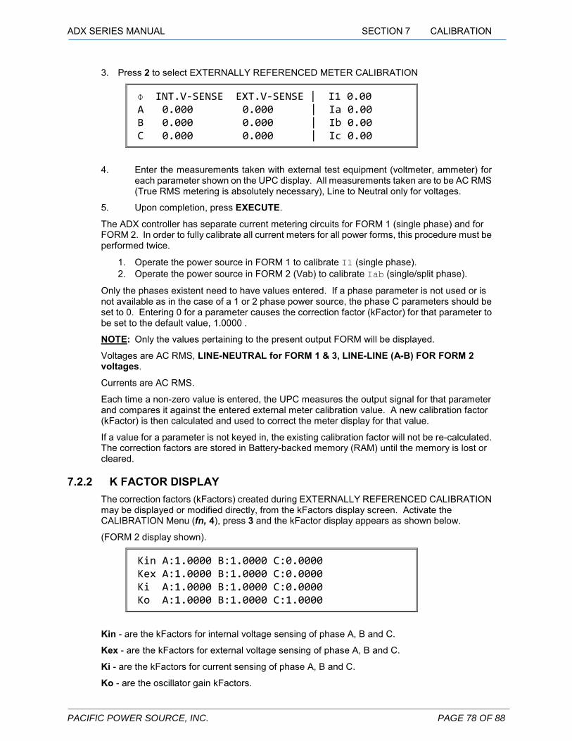
ADX SERIES MANUAL SECTION 7 CALIBRATION
PACIFIC POWER SOURCE, INC. PAGE 78 OF 88
3. Press 2 to select EXTERNALLY REFERENCED METER CALIBRATION
Ф INT.V-SENSE EXT.V-SENSE | I1 0.00 A 0.000 0.000 | Ia 0.00 B 0.000 0.000 | Ib 0.00 C 0.000 0.000 | Ic 0.00
4. Enter the measurements taken with external test equipment (voltmeter, ammeter) for each parameter shown on the UPC display. All measurements taken are to be AC RMS (True RMS metering is absolutely necessary), Line to Neutral only for voltages.
5. Upon completion, press EXECUTE.
The ADX controller has separate current metering circuits for FORM 1 (single phase) and for FORM 2. In order to fully calibrate all current meters for all power forms, this procedure must be performed twice.
1. Operate the power source in FORM 1 to calibrate I1 (single phase). 2. Operate the power source in FORM 2 (Vab) to calibrate Iab (single/split phase).
Only the phases existent need to have values entered. If a phase parameter is not used or is not available as in the case of a 1 or 2 phase power source, the phase C parameters should be set to 0. Entering 0 for a parameter causes the correction factor (kFactor) for that parameter to be set to the default value, 1.0000 .
NOTE: Only the values pertaining to the present output FORM will be displayed.
Voltages are AC RMS, LINE-NEUTRAL for FORM 1 & 3, LINE-LINE (A-B) FOR FORM 2 voltages.
Currents are AC RMS.
Each time a non-zero value is entered, the UPC measures the output signal for that parameter and compares it against the entered external meter calibration value. A new calibration factor (kFactor) is then calculated and used to correct the meter display for that value.
If a value for a parameter is not keyed in, the existing calibration factor will not be re-calculated. The correction factors are stored in Battery-backed memory (RAM) until the memory is lost or cleared.
7.2.2 K FACTOR DISPLAY
The correction factors (kFactors) created during EXTERNALLY REFERENCED CALIBRATION may be displayed or modified directly, from the kFactors display screen. Activate the CALIBRATION Menu (fn, 4), press 3 and the kFactor display appears as shown below.
(FORM 2 display shown).
Kin A:1.0000 B:1.0000 C:0.0000 Kex A:1.0000 B:1.0000 C:0.0000 Ki A:1.0000 B:1.0000 C:0.0000 Ko A:1.0000 B:1.0000 C:1.0000
Kin - are the kFactors for internal voltage sensing of phase A, B and C.
Kex - are the kFactors for external voltage sensing of phase A, B and C.
Ki - are the kFactors for current sensing of phase A, B and C.
Ko - are the oscillator gain kFactors.

ADX SERIES MANUAL SECTION 7 CALIBRATION
PACIFIC POWER SOURCE, INC. PAGE 79 OF 88
It is recommended that the kFactors are reset to 1.000 before calibration. The new kFactor is then the ratio of the external metered value to the UPC meter display value. This minimizes error and will provide the best results.
new kFactor = ( test equipment value ) UPC meter display value To manually calculate and revise a particular existing kFactor,
1. observe the UPC meter display value 2. use the following equation to calculate the new kFactor:
new kFactor = old kFactor X ( test equipment value ) UPC meter display value
7.2.3 RESET ALL KFACTORS
Resets all kFactors to the factory default (1.000). Activate the CALIBRATION Menu (fn, 4), press 1 and the kFactor reset warning appears as shown below.
WARNING: RECALIBRATION REQUIRED PRESS "EXECUTE" TO CONTINUE PRESS "CLEAR" TO CANCEL
WARNING: You will have to recalibrate your power source.
7.3 POWER SOURCE LOAD TEST These tests are used to verify that the power source is able to deliver full rated output power. Additionally, the output metering function of the controller is also checked.
1. Set the Power Source for FORM2 Output, CSC Enabled.
2. Attach a 6A, 2000W load to the rear panel Output Terminal.
3. Set the output for 300 V and close the Output Contactor.
4. Verify that the output voltage remains constant (within load regulation limits) and that
the Output metering reads correct values.
5. Open the Output Contactor.
6. Configure for FORM1 Output. Repeat above procedure with a 12A, 2000W load and
150 V.
7. Verify that the output voltage and Power Source meters read properly.

PACIFIC POWER SOURCE, INC. PAGE 80 OF 88
SECTION 8
SERVICE
8 SERVICE This section describes service of the ADX AC Power Source.
8.1 SERVICE PROCEDURE The ADX Power Source contains no user serviceable parts. Service is properly accomplished by returning the unit to the factory or authorized service center. Under some circumstances, the factory may authorize the user to perform limited sub-assembly or component changes as deemed allowable by the factory service representative. For this purpose, many sub-assembly and component level Pacific Power Source part numbers have been included here. Part numbers for various components are listed separately for each Model.
When questions regarding operation arise or service is required, call the factory for instructions. Pacific Power Source Corporation maintains a staff of highly trained technicians who are ready to assist. See the Pacific Power website for contact information (www.pacificpower.com ).
8.2 SYSTEM LEVEL FACTORY PART NUMBERS MODEL NAME PART No. MODEL 110ADX-UPC1 1.0 kVA AC Power Source with RS232 201706-AA MODEL 110ADX-UPC1/G 1.0 kVA AC Power Source with GPIB 201707-AA MODEL 115ADX-UPC1 1.5 kVA AC Power Source with RS232 201708-AA MODEL 115ADX-UPC1/G 1.5 kVA AC Power Source with GPIB 201709-AA
8.3 SUB-ASSEMBLY AND CHASSIS COMPONENT PART NUMBERS The factory part numbers given in the following list are provided to aid the user in obtaining spare or repair sub-assemblies and components where the factory has given permission, in advance, for the user to perform field repairs on the Power Source.
SUB-ASSEMBLY FACTORY PART No. UPC1 Programmable 1φ Controller: 141170 LCD Display Assembly: 139071 Power Amplifier Assembly: 200431 Input PFC Assembly: 200418 Keyboard Assembly: 200437 Input Filter Assembly: 200434 COMPONENT FACTORY PART No. Input Circuit Breaker: 716095 Front Panel Handle: 200526 Output Terminal Block: 705113 Input Terminal Block: 705113 Fan: 703200 Fuse: 712088
Table 8-1: SPARE PARTS LIST

PACIFIC POWER SOURCE, INC. PAGE 81 OF 88
SECTION 9
MODIFICATIONS AND CHANGE NOTICES
9 MODIFICATIONS AND CHANGE NOTICES In cases where customer specified modifications have been installed in the equipment, the modifications will be described on the following pages. If present, be sure to notice any special instructions relative to operation and calibration of the system.
Product change notices or manual errata will be provided in hard copy format. If you printed out this manual, please place these additional pages in this section.

ADX SERIES MANUAL SECTION 10 SERIAL REMOTE INTERFACE
PACIFIC POWER SOURCE, INC. PAGE 82 OF 88
SECTION 10
SERIAL REMOTE INTERFACE
10 SERIAL REMOTE INTERFACE This section describes using the optional Serial Remote Interface of the UPC. This section is intended to be used in conjunction with (5.0) of this Operation Manual.
10.1 GENERAL The Serial Remote Interface of the UPC is the standard communication port for the UPC-1. See (10.3) for setup information. An optional GPIB/IEEE-488 parallel communication port may be installed in place of the serial port. Check the connector label at the rear of the unit to determine which interface is installed.
10.2 SERIAL PORT SPECIFICATIONS The Serial Remote Interface of the UPC is compatible with the ANSI/IEEE-488.2, SCPI and RS-232C standards. It loosely adheres to the RS-232C standard as some interfacing requirements of that standard are not necessary.
This Remote Interface of the UPC has the following communication characteristics:
1. Selectable BAUD RATES of: 38400 BAUD 19200 BAUD (default) 9600 BAUD 4800 BAUD 2400 BAUD 1200 BAUD 300 BAUD
2. Selectable PARITY of ODD, EVEN or NONE (default).
3. Selectable EOS (End Of String) Terminator CR, LF or CR/LF (default): Sets the EOS sent from the UPC. The UPC accepts any of the above combinations when receiving.
4. 8 Data bits, 1 Start bit, 1 Stop bit.
5. HANDSHAKE: None.
Note: The Serial Remote interface of the UPC has no Handshake. This is a simple 2 wire interface.
6. Operation is HALF-DUPLEX (per IEEE-488.2).
Refer to (10.6) below for Pinouts and Signal names.

PACIFIC POWER SOURCE, INC. PAGE 83 OF 88
10.3 SETUP After installing the Serial Interface into the UPC - OR - after erasing all program memory – OR - after system RESET, the serial communication parameters must be set (BAUD RATE, PARITY and EOS Terminator) as follows:
1. Press the fn key, select GENERAL SETUP then UPC STATUS.
2. Press the EDIT key and type the desired BAUD RATE numerically, selected from the list above. Then press ENTER.
3. Select the PARITY by pressing the +/- key until the desired selection (NONE, ODD or EVEN) is shown. Then press ENTER.
4. Select EOS (End Of String) Terminator by pressing the +/- key until the desired selection (CR/LF, LF or CR) is shown. Then press ENTER.
5. Press STORE.
NOTE: Incorrect communication parameters may result in the UPC displaying a: PARITY ERROR, FRAMING ERROR, and/or OVERRUN ERROR.
Sending a BREAK signal will result in a BREAK RCVD message and will terminate data transmission in progress from the UPC.
10.4 OPERATION Operation of the UPC via Remote Serial Interface consists of utilizing the same commands available for the IEEE-488 interface (5.0) except as noted in (10.4.1), (10.4.2), and (10.4.3).
NOTE: Normally the UPC is in the LISTENER mode. When the UPC is Queried for information, the UPC automatically enters the Talker mode until the response data is sent or another command is sent from the Host.
10.4.1 COMMUNICATION MONITORING AID The UPC STATUS Display (fn,3,3) displays "LISTENER" while data is being received from the HOST, or "TALKER" if a Query response (Message Available) is available and has not yet been completely sent by the UPC.
The UPC STATUS Display will display the LAST DATA BYTE received from the HOST. Carriage Returns (0Dhex) are displayed as Line Feeds (0Ahex).
This monitoring aid is not updated as fast as serial communications can occur, therefore sudden changes on the Serial Interface may not be seen on the UPC display.
The ADX controller does not support RTS/CTS.
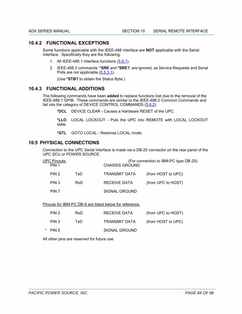
ADX SERIES MANUAL SECTION 10 SERIAL REMOTE INTERFACE
PACIFIC POWER SOURCE, INC. PAGE 84 OF 88
10.4.2 FUNCTIONAL EXCEPTIONS Some functions applicable with the IEEE-488 interface are NOT applicable with the Serial Interface. Specifically they are the following:
1. All IEEE-488.1 interface functions (5.6.1).
2. IEEE-488.2 commands: *SRE and *SRE?, are ignored, as Service Requests and Serial Polls are not applicable (5.5.3.1).
(Use *STB? to obtain the Status Byte.)
10.4.3 FUNCTIONAL ADDITIONS The following commands have been added to replace functions lost due to the removal of the IEEE-488.1 GPIB. These commands are similar to the IEEE-488.2 Common Commands and fall into the category of DEVICE CONTROL COMMANDS (5.6.2).
*DCL DEVICE CLEAR - Causes a Hardware RESET of the UPC. *LLO LOCAL LOCKOUT - Puts the UPC into REMOTE with LOCAL LOCKOUT state. *GTL GOTO LOCAL - Restores LOCAL mode.
10.5 PHYSICAL CONNECTIONS Connection to the UPC Serial Interface is made via a DB-25 connector on the rear panel of the UPC SCU or POWER SOURCE.
UPC Pinouts: (For connection to IBM-PC type DB-25) PIN 1
CHASSIS GROUND
PIN 2
TxD TRANSMIT DATA (from HOST to UPC)
PIN 3
RxD RECEIVE DATA (from UPC to HOST)
PIN 7
SIGNAL GROUND
Pinouts for IBM-PC DB-9 are listed below for reference. PIN 2
RxD RECEIVE DATA (from UPC to HOST)
PIN 3
TxD TRANSMIT DATA (from HOST to UPC)
* PIN 5
SIGNAL GROUND
All other pins are reserved for future use.

PACIFIC POWER SOURCE, INC. PAGE 85 OF 88
10.6 TESTING THE SERIAL REMOTE INTERFACE 1. Connect the UPC Serial Interface to a DTE serial port of a PC using a DB-25 cable. Most 25
pin connectors on PC's are DTE type. The UPC is a DCE type and must connect to a DTE port. If using a 9 pin connector on the PC, verify the pinouts of the cable match the UPC to the PC correctly.
2. Configure the PC Baud Rate to 19200 or 9600 Baud, No Parity, 8 Data bits, 1 stop, 1 start bit using a terminal emulation program. Ensure the UPC is configured the same (see (10.3) of this manual for setup). Leave the EOS set to CR/LF.
3. Enter the UPC STATUS display of the UPC (fn,3,3), do NOT press EDIT this time. See (10.4.1) for info on the COMMUNICATION MONITORING AID.
4. Send Executable commands from the PC such as :SYST:BEEP, :VOLTS 100, :FREQ 50, and verify that the UPC responds correctly.
5. Send Query commands from the PC such as *IDN?, FETCH:VOLT1?, and verify that the PC receives correct data from the UPC after each Query command is sent. No other operation is needed to cause the UPC to send the response data.

ADX SERIES MANUAL SECTION 10 SERIAL REMOTE INTERFACE
PACIFIC POWER SOURCE, INC. PAGE 86 OF 88
SECTION 10
11 INDEX
A
Airflow ............................................................ 23, 25 Altitude ................................................................. 23 Amps to Volts Ratio Setting .............................. 25 AUX I/O ............................................................... 29
B
Bandwidth ........................................................... 18
C
Caution .................................................... 12, 48, 49 CSC ...................................................................... 14 Current Limit ....................................................... 19
D
DC Offset............................................................. 19
E
External Sense ................................................... 32
I
Input Current ADX ................................................................. 15
Isolation ............................................................... 19
O
Output Current .................................................... 16 Overload .............................................................. 16
Over-temperature ............................................... 50
P
Pollution Degree .............................................. 23 Power Factor ................................................ 16, 18
R
Regulation ........................................................... 18 Remote Interface
GPIB ................................................................ 25 RS-232 ...................................................... 25, 29
S
Shutdown Conditions ...................................................... 50 Fault .......................................................... 23, 50 Reset ............................................................... 50
Split Phase .......................................................... 28
T
THD ...................................................................... 18 Transient Response .......................................... 18
V
Ventilation ........................................................... 25
W
Warning ............................................. 11, 12, 24, 28

PACIFIC POWER SOURCE, INC. PAGE 87 OF 88

ADX SERIES MANUAL SECTION 10 SERIAL REMOTE INTERFACE
PACIFIC POWER SOURCE, INC. PAGE 88 OF 88


![Method for unsupervised classification of multiunit neural signal …s-space.snu.ac.kr/bitstream/10371/7842/1/[2003-2] Method... · 2019-04-29 · IEEE TRANSACTIONS ON BIOMEDICAL](https://img.pdfslide.us/doc/110x75/5f3e972b0e9c6f55115e51d9/method-for-unsupervised-classification-of-multiunit-neural-signal-s-spacesnuackrbitstream10371784212003-2.jpg)