Embed Size (px)
Citation preview
AdventurerTM Balances
Service Manual

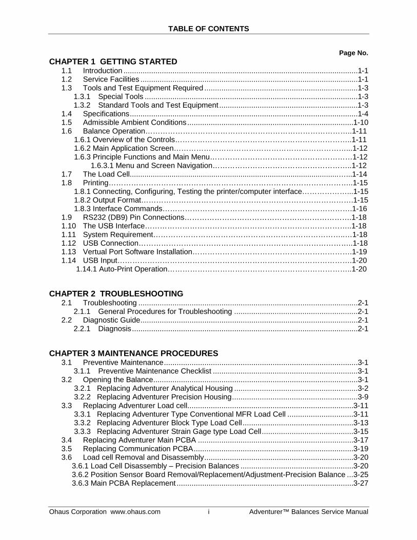
TABLE OF CONTENTS
Ohaus Corporation www.ohaus.com i Adventurer™ Balances Service Manual
Page No. CHAPTER 1 GETTING STARTED
1.1 Introduction ..............................................................................................................1-1 1.2 Service Facilities ......................................................................................................1-1 1.3 Tools and Test Equipment Required ........................................................................1-3
1.3.1 Special Tools ....................................................................................................1-3 1.3.2 Standard Tools and Test Equipment .................................................................1-3
1.4 Specifications ...........................................................................................................1-4 1.5 Admissible Ambient Conditions .............................................................................. 1-10 1.6 Balance Operation………………………………………………………………………..1-11 1.6.1 Overview of the Controls……………………………………………………………..1-11 1.6.2 Main Application Screen……………………………………………………………...1-12 1.6.3 Principle Functions and Main Menu…………………………………………………1-12 1.6.3.1 Menu and Screen Navigation………………………………………………..1-12 1.7 The Load Cell....................................................................................................…...1-14 1.8 Printing……………………………………………………………………………………..1-15 1.8.1 Connecting, Configuring, Testing the printer/computer interface………………...1-15 1.8.2 Output Format………………………………………………………………………….1-15 1.8.3 Interface Commands………………………………………………………………….1-16 1.9 RS232 (DB9) Pin Connections………………………………………………………….1-18 1.10 The USB Interface………………………………………………………………………..1-18 1.11 System Requirement…………………………………………………………………..…1-18 1.12 USB Connection…………………………………………………………………………..1-18 1.13 Vertual Port Software Installation……………………………………………………….1-19 1.14 USB Input………………………………………………………………………………….1-20 1.14.1 Auto-Print Operation………………………………………………………………..1-20
CHAPTER 2 TROUBLESHOOTING
2.1 Troubleshooting .......................................................................................................2-1 2.1.1 General Procedures for Troubleshooting ..........................................................2-1
2.2 Diagnostic Guide ......................................................................................................2-1 2.2.1 Diagnosis ..........................................................................................................2-1
CHAPTER 3 MAINTENANCE PROCEDURES
3.1 Preventive Maintenance ...........................................................................................3-1 3.1.1 Preventive Maintenance Checklist ....................................................................3-1
3.2 Opening the Balance ................................................................................................3-1 3.2.1 Replacing Adventurer Analytical Housing ..........................................................3-2 3.2.2 Replacing Adventurer Precision Housing ...........................................................3-9 3.3 Replacing Adventurer Load cell.............................................................................. 3-11 3.3.1 Replacing Adventurer Type Conventional MFR Load Cell ............................... 3-11 3.3.2 Replacing Adventurer Block Type Load Cell .................................................... 3-13 3.3.3 Replacing Adventurer Strain Gage type Load Cell ........................................... 3-15 3.4 Replacing Adventurer Main PCBA ......................................................................... 3-17 3.5 Replacing Communication PCBA ........................................................................... 3-19 3.6 Load cell Removal and Disassembly ...................................................................... 3-20 3.6.1 Load Cell Disassembly – Precision Balances ..................................................... 3-20 3.6.2 Position Sensor Board Removal/Replacement/Adjustment-Precision Balance ... 3-25 3.6.3 Main PCBA Replacement ................................................................................... 3-27
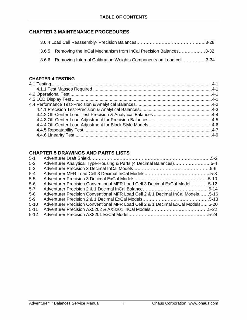
TABLE OF CONTENTS
Adventurer™ Balances Service Manual ii Ohaus Corporation www.ohaus.com
CHAPTER 3 MAINTENANCE PROCEDURES
3.6.4 Load Cell Reassembly- Precision Balances………………………………………..3-28
3.6.5 Removing the InCal Mechanism from InCal Precision Balances………………3-32
3.6.6 Removing Internal Calibration Weights Components on Load cell…………….3-34
CHAPTER 4 TESTING 4.1 Testing ...............................................................................................................................4-1 4.1.1 Test Masses Required ..............................................................................................4-1 4.2 Operational Test ................................................................................................................4-1 4.3 LCD Display Test ...............................................................................................................4-1 4.4 Performance Test-Precision & Analytical Balances ............................................................4-2 4.4.1 Precision Test-Precision & Analytical Balances .........................................................4-3 4.4.2 Off-Center Load Test Precision & Analytical Balances ..............................................4-4 4.4.3 Off-Center Load Adjustment for Precision Balances ..................................................4-5 4.4.4 Off-Center Load Adjustment for Block Style Models ..................................................4-6 4.4.5 Repeatability Test......................................................................................................4-7 4.4.6 Linearity Test .............................................................................................................4-9 CHAPTER 5 DRAWINGS AND PARTS LISTS 5-1 Adventurer Draft Shield……………………………………………………………………….5-2 5-2 Adventurer Analytical Type-Housing & Parts (4 Decimal Balances)…………………….5-4 5-3 Adventurer Precision 3 Decimal InCal Models…………………………………………….5-6 5-4 Adventurer MFR Load Cell 3 Decimal InCal Models……………………………………...5-8 5-5 Adventurer Precision 3 Decimal ExCal Models…………………………………………..5-10 5-6 Adventurer Precision Conventional MFR Load Cell 3 Decimal ExCal Model…………5-12 5-7 Adventurer Precision 2 & 1 Decimal InCal Balance……………………………………...5-14 5-8 Adventurer Precision Conventional MFR Load Cell 2 & 1 Decimal InCal Models…….5-16 5-9 Adventurer Precision 2 & 1 Decimal ExCal Models………………………………………5-18 5-10 Adventurer Precision Conventional MFR Load Cell 2 & 1 Decimal ExCal Models…...5-20 5-11 Adventurer Precision AX5202 & AX8201 InCal Models…………………………………5-22 5-12 Adventurer Precision AX8201 ExCal Model………………………………………………5-24
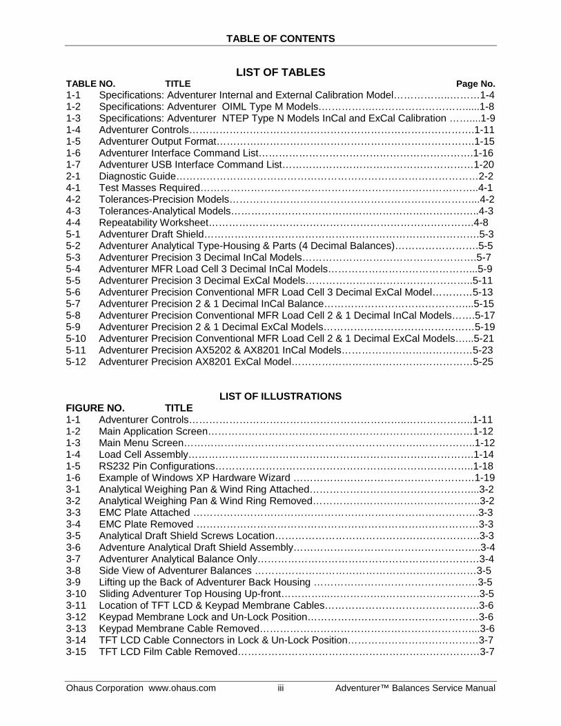
TABLE OF CONTENTS
Ohaus Corporation www.ohaus.com iii Adventurer™ Balances Service Manual
LIST OF TABLES TABLE NO. TITLE Page No. 1-1 Specifications: Adventurer Internal and External Calibration Model……………..………1-4 1-2 Specifications: Adventurer OIML Type M Models.…………….……………………….....1-8 1-3 Specifications: Adventurer NTEP Type N Models InCal and ExCal Calibration ……....1-9 1-4 Adventurer Controls………………………………………………………………………….1-11 1-5 Adventurer Output Format………….……………………………………………………….1-15 1-6 Adventurer Interface Command List……………………………………………………….1-16 1-7 Adventurer USB Interface Command List…………………………………………………1-20 2-1 Diagnostic Guide………………………………………………………………………………2-2 4-1 Test Masses Required………………………………………………………………………..4-1 4-2 Tolerances-Precision Models………………………………………………………………...4-2 4-3 Tolerances-Analytical Models………………………………………………………………..4-3 4-4 Repeatability Worksheet…………………………………………………………………….4-8 5-1 Adventurer Draft Shield……………………………………………………………………….5-3 5-2 Adventurer Analytical Type-Housing & Parts (4 Decimal Balances)…………………….5-5 5-3 Adventurer Precision 3 Decimal InCal Models…………………………………………….5-7 5-4 Adventurer MFR Load Cell 3 Decimal InCal Models……………………………………...5-9 5-5 Adventurer Precision 3 Decimal ExCal Models…………………………………………..5-11 5-6 Adventurer Precision Conventional MFR Load Cell 3 Decimal ExCal Model…………5-13 5-7 Adventurer Precision 2 & 1 Decimal InCal Balance……………………………………...5-15 5-8 Adventurer Precision Conventional MFR Load Cell 2 & 1 Decimal InCal Models…….5-17 5-9 Adventurer Precision 2 & 1 Decimal ExCal Models………………………………………5-19 5-10 Adventurer Precision Conventional MFR Load Cell 2 & 1 Decimal ExCal Models…...5-21 5-11 Adventurer Precision AX5202 & AX8201 InCal Models…………………………………5-23 5-12 Adventurer Precision AX8201 ExCal Model………………………………………………5-25
LIST OF ILLUSTRATIONS FIGURE NO. TITLE 1-1 Adventurer Controls………………………………………………………..………………..1-11 1-2 Main Application Screen……………………………………………………….……………1-12 1-3 Main Menu Screen…………………………………………………………….……………..1-12 1-4 Load Cell Assembly………………………………………………………………………….1-14 1-5 RS232 Pin Configurations…………………………………………………………………..1-18 1-6 Example of Windows XP Hardware Wizard ………………………………………………1-19 3-1 Analytical Weighing Pan & Wind Ring Attached…………………………………………...3-2 3-2 Analytical Weighing Pan & Wind Ring Removed…………………………………………..3-2 3-3 EMC Plate Attached ………………………………………………………………………….3-3 3-4 EMC Plate Removed …………………………………………………………………………3-3 3-5 Analytical Draft Shield Screws Location…………………………………………………….3-3 3-6 Adventure Analytical Draft Shield Assembly………………………………………………..3-4 3-7 Adventurer Analytical Balance Only…………………………………………………………3-4 3-8 Side View of Adventurer Balances …………………………………………………………3-5 3-9 Lifting up the Back of Adventurer Back Housing ………………………………………….3-5 3-10 Sliding Adventurer Top Housing Up-front…………...……………..……………………….3-5 3-11 Location of TFT LCD & Keypad Membrane Cables……………………………………….3-6 3-12 Keypad Membrane Lock and Un-Lock Position……………………………………………3-6 3-13 Keypad Membrane Cable Removed………………………………………………………...3-6 3-14 TFT LCD Cable Connectors in Lock & Un-Lock Position…………………………………3-7 3-15 TFT LCD Film Cable Removed………………………………………………………………3-7
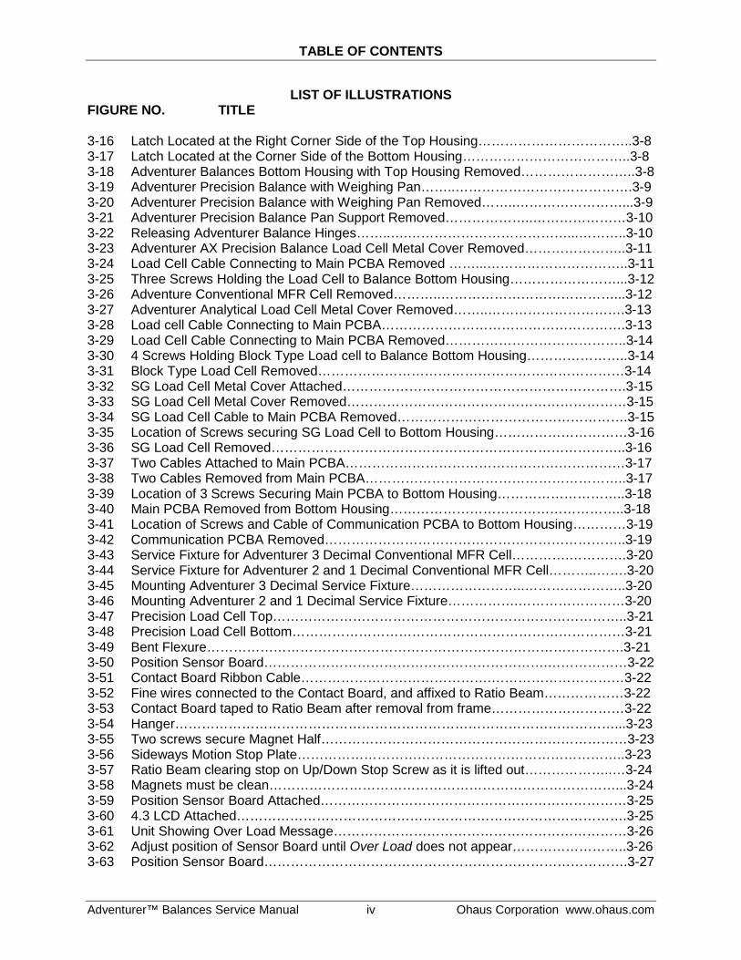
TABLE OF CONTENTS
Adventurer™ Balances Service Manual iv Ohaus Corporation www.ohaus.com
LIST OF ILLUSTRATIONS FIGURE NO. TITLE 3-16 Latch Located at the Right Corner Side of the Top Housing……………………………..3-8 3-17 Latch Located at the Corner Side of the Bottom Housing………………………………..3-8 3-18 Adventurer Balances Bottom Housing with Top Housing Removed……………………..3-8 3-19 Adventurer Precision Balance with Weighing Pan……..………………………………….3-9 3-20 Adventurer Precision Balance with Weighing Pan Removed……..……………………...3-9 3-21 Adventurer Precision Balance Pan Support Removed………………..…………………3-10 3-22 Releasing Adventurer Balance Hinges……..….………………………………...………..3-10 3-23 Adventurer AX Precision Balance Load Cell Metal Cover Removed…………………..3-11 3-24 Load Cell Cable Connecting to Main PCBA Removed ……...…………………………..3-11 3-25 Three Screws Holding the Load Cell to Balance Bottom Housing……………………...3-12 3-26 Adventure Conventional MFR Cell Removed………..…………………………………...3-12 3-27 Adventurer Analytical Load Cell Metal Cover Removed……..………………………….3-13 3-28 Load cell Cable Connecting to Main PCBA……………………………………………….3-13 3-29 Load Cell Cable Connecting to Main PCBA Removed…………………………………..3-14 3-30 4 Screws Holding Block Type Load cell to Balance Bottom Housing…………………..3-14 3-31 Block Type Load Cell Removed……………………………………………………………3-14 3-32 SG Load Cell Metal Cover Attached……………………………………………………….3-15 3-33 SG Load Cell Metal Cover Removed………………………………………………………3-15 3-34 SG Load Cell Cable to Main PCBA Removed…………………………………………….3-15 3-35 Location of Screws securing SG Load Cell to Bottom Housing…………………………3-16 3-36 SG Load Cell Removed……………………………………………………………………..3-16 3-37 Two Cables Attached to Main PCBA………………………………………………………3-17 3-38 Two Cables Removed from Main PCBA…………………………………………………..3-17 3-39 Location of 3 Screws Securing Main PCBA to Bottom Housing………………………..3-18 3-40 Main PCBA Removed from Bottom Housing……………………………………………..3-18 3-41 Location of Screws and Cable of Communication PCBA to Bottom Housing…………3-19 3-42 Communication PCBA Removed…………………………………………………………..3-19 3-43 Service Fixture for Adventurer 3 Decimal Conventional MFR Cell………….………….3-20 3-44 Service Fixture for Adventurer 2 and 1 Decimal Conventional MFR Cell………..…….3-20 3-45 Mounting Adventurer 3 Decimal Service Fixture……………………..…………………..3-20 3-46 Mounting Adventurer 2 and 1 Decimal Service Fixture…………….……………………3-20 3-47 Precision Load Cell Top……………………………………………………………………..3-21 3-48 Precision Load Cell Bottom…………………………………………………………………3-21 3-49 Bent Flexure………………………………………………………………………………….3-21 3-50 Position Sensor Board……………………………………………………….………………3-22 3-51 Contact Board Ribbon Cable…………………………………….…………………………3-22 3-52 Fine wires connected to the Contact Board, and affixed to Ratio Beam………………3-22 3-53 Contact Board taped to Ratio Beam after removal from frame…………………………3-22 3-54 Hanger………………………………………………………………………………………...3-23 3-55 Two screws secure Magnet Half……………………………………………………………3-23 3-56 Sideways Motion Stop Plate………………………………………………………………..3-23 3-57 Ratio Beam clearing stop on Up/Down Stop Screw as it is lifted out………………..…3-24 3-58 Magnets must be clean……………………………………………………………………...3-24 3-59 Position Sensor Board Attached……………………………………………………………3-25 3-60 4.3 LCD Attached…………………………………………………………………………….3-25 3-61 Unit Showing Over Load Message…………………………………………………………3-26 3-62 Adjust position of Sensor Board until Over Load does not appear……………………..3-26 3-63 Position Sensor Board……………………………………………………………………….3-27
TABLE OF CONTENTS
Ohaus Corporation www.ohaus.com v Adventurer™ Balances Service Manual
LIST OF ILLUSTRATIONS FIGURE NO. TITLE 3-64 Installing Ratio Beam, clearing the Up/down Stop Screw……………………………….3-28 3-65 Precision Load Cell 3 Decimal top, with Service Fixture attached…………………..….3-28 3-66 Service Fixture for 2 and 1 Decimal Precision Load Cell, attached to Hange…………3-28 3-67 Sideways Motion Stop Plate………………………………………………………………..3-29 3-68 Two screws secure Magnet Half……………………………………………………………3-29 3-69 Contact Board………………………………………………………………………………...3-29 3-70 Solder points on Position Sensor Board…………………………………………………..3-29 3-71 Precision Load Cell top……………………………………………………………………...3-30 3-72 Precision Load Cell bottom………………………………………………………………....3-30 3-73 Ratio Beam Flexures and Vertical Flexure……………………………………………..…3-30 3-74 Insert the 3 screws to secure Precision Load Cell in Bottom Housing…………………3-30 3-75 When Position Sensor Board shows normal weight, tighten its screws…………….…3-31 3-76 Location of the 4 screws holding the weight protection metal plate……………………3-32 3-77 Location of the two weight retainer………………………………………………………..3-32 3-78 Weight retainer removed……………………………………………………………………3-33 3-79 Picture showing InCal weight removed and showing the InCal mechanism….............3-33 3-80 Location of the two screws holding the weighing arm assembly in place……………...3-34 3-81 Weighing arm assembly removed………………………………………………………….3-34 4-1 Adventurer LCD Boot Up Screen………………………………….………………………...4-2 4-2 Analytical & Precision Balances Mass Placement Locations for Off-Center Load Test.4-4 4-3 Off-Center Load Adjustments on Adventurer Precisions Balance……...………………..4-5 4-4 Off-Center Load Adjustment Screws Hole on Adventurer Precision Balances……...….4-5 4-5 Using Needle File to Adjust Off-Center Load on Block Type Load Cell…………………4-6 5-1 Adventurer Draft Shield……………………………………………………………………….5-2 5-2 Adventurer Analytical Type-Housing & Parts (4 Decimal Balances)…………………….5-4 5-3 Adventurer Precision 3 Decimal InCal Models…………………………………………….5-6 5-4 Adventurer MFR Load Cell 3 Decimal InCal Models……………………………………...5-8 5-5 Adventurer Precision 3 Decimal ExCal Models…………………………………………..5-10 5-6 Adventurer Precision Conventional MFR Load Cell 3 Decimal ExCal Model…………5-12 5-7 Adventurer Precision 2 & 1 Decimal InCal Balance……………………………………...5-14 5-8 Adventurer Precision Conventional MFR Load Cell 2 & 1 Decimal InCal Models…….5-16 5-9 Adventurer Precision 2 & 1 Decimal ExCal Models………………………………………5-18 5-10 Adventurer Precision Conventional MFR Load Cell 2 & 1 Decimal ExCal Models…...5-20 5-11 Adventurer Precision AX5202 & AX8201 InCal Models…………………………………5-22 5-12 Adventurer Precision AX8201 ExCal Model………………………………………………5-24
TABLE OF CONTENTS
Adventurer™ Balances Service Manual vi Ohaus Corporation www.ohaus.com
LIST OF ILLUSTRATIONS FIGURE NO. TITLE A-1 Adventurer Overlay…….…………………………………………………………………….A-1 A-2 Service Mode Window 1……………………………………………………………………..A-2 A-3 Service Mode Window 2……………………………………………………………………..A-2 A-4 Service Mode Ramp…………………………………………………………………………..A-3 A-5 Service Mode Software Upgrade…………………………………………………………....A-4 A-6 Service Mode Software Upgrade Window, USB Connection and Software Version..…A-4 A-7 Service Mode 3 Point Linearity Calibration…………………………………………………A-5 A-8 Service Mode 5 Point Linearity Calibration………………………………………………...A-6 A-9 Service Mode Internal Weight Calibration………………………………………………….A-7 A-10 Service Mode Span Calibration…….………………………………………………………..A-7 A-11 Service Mode Internal Calibration…………………………………………………………..A-8 A-12 Service Mode Internal Repeatability Test………………………………………………….A-8 A-13 Service Mode Balance Information…………………………………………………………A-9 A-14 Service Mode Calibration Data……………………………………………………………...A-9 A-15 Service Mode Calibration Data Information Window…………………………………….A-10 B-1 Software Selection……………………………………………………………………..……..B-1 B-2 Product Selection……………………………………………………………………………..B-2 B-3 Restore EEPROM…………………………………………………………………………….B-3 B-4 Write Image File……………………………………………………………………………….B-3 B-5 COM Port Configuration……………………….,…………………………………………….B-4 B-6 Write Image File……………………………………………………………………………….B-5 B-7 Replace Load Cell Tab……………………………………………………………………….B-6 B-8 Function Selection Replace Load Cell………………………………………………………B-6 B-9 Replace Main PCB Tab………………………………………………………………………B-7 B-10 Function Selection Replace Main PCB……………………………………………………..B-7 B-11 Download Software Tab………………………………………………………………………B-8 B-12 Diagnostics Tab……………………………………………………………………………….B-9 B-13 Diagnostics Command Testing……………………………………………………………...B-9 Appendix A SERVICE MENU
A.1 Entering the Service Menu ...................................................................................... A-1 A.2 Service Ramp ......................................................................................................... A-3 A.3 Service Software Upgrade ...................................................................................... A-4 A.4 Service 3 Point Linearity Calibration ........................................................................ A-5 A.5 Service 5 Point Linearity Calibration ........................................................................ A-6 A.6 Service Internal Weight Calibration ......................................................................... A-7 A.7 Service Span Calibration ......................................................................................... A-7 A.8 Service Internal Calibration ..................................................................................... A-8 A.9 Service Internal Repeatability Test .......................................................................... A-8 A.10 Service Balance Information ................................................................................... A-9 A.11 Service Calibration Data ......................................................................................... A-9
TABLE OF CONTENTS
Ohaus Corporation www.ohaus.com vii Adventurer™ Balances Service Manual
Appendix B SOFTWARE SERVICE & REPAIR TOOLS INSTRUCTIONS B-1 Software Installation and Software Selection……………………………………..…… B-1 B.2 Product Selection……………………………………………………………..…….……...B-2 B.3 To Restore the EEPROM Data………………………………………………….………..B-2 B.4 COM Port Configuration…………………………………………………………………...B-4 B.5 To Replace a Load Cell………………………………………………………………...….B-5 B.6 Install New Main Printed Circuit Board (PCBA)…………………………………...…….B-7 B.7 Update the Software in the Balance……………………………………………..……….B-8 B.8 Diagnostics……………………………………………………………..…………...………B-9 B.9 InCal Weight Mechanism Testing……………………………………………….………B-10

CHAPTER 1 GETTING STARTED
Adventurer ™ Balances Service Manual 1-1 Ohaus Corporation www.ohaus.com
1.1 INTRODUCTION
This service manual contains the information needed to perform routine maintenance and service on the Ohaus Adventurer (AX) Precision and Analytical balances.
Before servicing the balance, you should be familiar with the Instruction Manual which is packed with every balance.
1.2 SERVICE FACILITIES
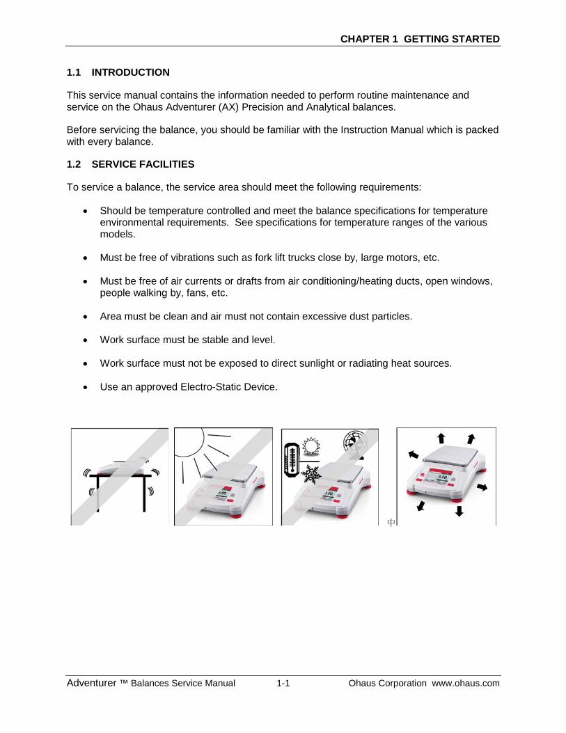
To service a balance, the service area should meet the following requirements:
• Should be temperature controlled and meet the balance specifications for temperature environmental requirements. See specifications for temperature ranges of the various models.
• Must be free of vibrations such as fork lift trucks close by, large motors, etc.
• Must be free of air currents or drafts from air conditioning/heating ducts, open windows, people walking by, fans, etc.
• Area must be clean and air must not contain excessive dust particles.
• Work surface must be stable and level.
• Work surface must not be exposed to direct sunlight or radiating heat sources.
• Use an approved Electro-Static Device.
中
CHAPTER 1 GETTING STARTED
Ohaus Corporation www.ohaus.com 1-2 Adventurer ™ Balances Service Manual
1.3 TOOLS AND TEST EQUIPMENT REQUIRED
1.3.1 Special Tools
1. Fixture P/N 923345 Corp. Item No. 00923345 for use with 150g to 410g Load Cells.
2. Fixture P/N 923389 Corp. Item No. 00923389 for use with 510g to 4100g Load Cells.
1.3.2 Standard Tools and Test Equipment
1. Digital Voltmeter (DVM) – Input impedance at least 10 megohms in 1 V DC position.
2. Nutdriver, 6mm.
3. Hex or Allen key wrenches, metric.
4. Other assorted hand tools, tweezers, adjustable open wrenches, etc.
5. Soldering iron (50 watt) and solder (rosin core solder, not acid core).
6. Solder remover.
CHAPTER 1 GETTING STARTED
Adventurer ™ Balances Service Manual 1-3 Ohaus Corporation www.ohaus.com
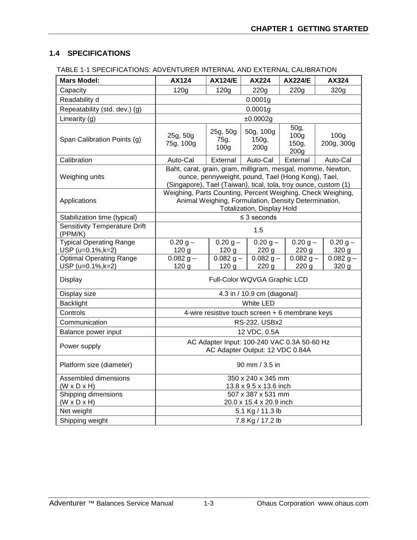
1.4 SPECIFICATIONS
TABLE 1-1 SPECIFICATIONS: ADVENTURER INTERNAL AND EXTERNAL CALIBRATION Mars Model: AX124 AX124/E AX224 AX224/E AX324 Capacity 120g 120g 220g 220g 320g Readability d 0.0001g Repeatability (std. dev.) (g) 0.0001g Linearity (g) ±0.0002g
Span Calibration Points (g) 25g, 50g 75g, 100g
25g, 50g 75g, 100g
50g, 100g 150g, 200g
50g, 100g 150g, 200g
100g 200g, 300g
Calibration Auto-Cal External Auto-Cal External Auto-Cal
Weighing units Baht, carat, grain, gram, milligram, mesgal, momme, Newton,
ounce, pennyweight, pound, Tael (Hong Kong), Tael, (Singapore), Tael (Taiwan), tical, tola, troy ounce, custom (1)
Applications Weighing, Parts Counting, Percent Weighing, Check Weighing,
Animal Weighing, Formulation, Density Determination, Totalization, Display Hold
Stabilization time (typical) ≤ 3 seconds Sensitivity Temperature Drift (PPM/K) 1.5
Typical Operating Range USP (u=0.1%,k=2)
0.20 g – 120 g
0.20 g – 120 g
0.20 g – 220 g
0.20 g – 220 g
0.20 g – 320 g
Optimal Operating Range USP (u=0.1%,k=2)
0.082 g – 120 g
0.082 g – 120 g
0.082 g – 220 g
0.082 g – 220 g
0.082 g – 320 g
Display Full-Color WQVGA Graphic LCD
Display size 4.3 in / 10.9 cm (diagonal) Backlight White LED Controls 4-wire resistive touch screen + 6 membrane keys Communication RS-232, USBx2 Balance power input 12 VDC, 0.5A
Power supply AC Adapter Input: 100-240 VAC 0.3A 50-60 Hz AC Adapter Output: 12 VDC 0.84A
Platform size (diameter) 90 mm / 3.5 in
Assembled dimensions (W x D x H)
350 x 240 x 345 mm 13.8 x 9.5 x 13.6 inch
Shipping dimensions (W x D x H)
507 x 387 x 531 mm 20.0 x 15.4 x 20.9 inch
Net weight 5.1 Kg / 11.3 lb Shipping weight 7.8 Kg / 17.2 lb
CHAPTER 1 GETTING STARTED
Ohaus Corporation www.ohaus.com 1-4 Adventurer ™ Balances Service Manual
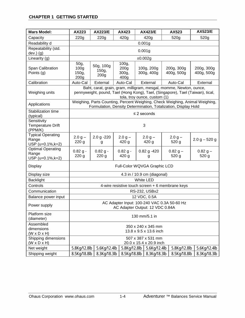
Mars Model: AX223 AX223/E AX423 AX423/E AX523 AX523/E Capacity 220g 220g 420g 420g 520g 520g Readability d 0.001g Repeatability (std. dev.) (g) 0.001g
Linearity (g) ±0.002g
Span Calibration Points (g)
50g, 100g 150g, 200g
50g, 100g 150g, 200g
100g, 200g 300g, 400g
100g, 200g 300g, 400g
200g, 300g 400g, 500g
200g, 300g 400g, 500g
Calibration Auto-Cal External Auto-Cal External Auto-Cal External
Weighing units Baht, carat, grain, gram, milligram, mesgal, momme, Newton, ounce,
pennyweight, pound, Tael (Hong Kong), Tael, (Singapore), Tael (Taiwan), tical, tola, troy ounce, custom (1)
Applications Weighing, Parts Counting, Percent Weighing, Check Weighing, Animal Weighing, Formulation, Density Determination, Totalization, Display Hold
Stabilization time (typical) ≤ 2 seconds
Sensitivity Temperature Drift (PPM/K)
3
Typical Operating Range USP (u=0.1%,k=2)
2.0 g – 220 g
2.0 g -220 g
2.0 g – 420 g
2.0 g – 420 g
2.0 g – 520 g 2.0 g – 520 g
Optimal Operating Range USP (u=0.1%,k=2)
0.82 g -220 g
0.82 g -220 g
0.82 g -420 g
0.82 g -420 g
0.82 g – 520 g
0.82 g – 520 g
Display Full-Color WQVGA Graphic LCD
Display size 4.3 in / 10.9 cm (diagonal) Backlight White LED Controls 4-wire resistive touch screen + 6 membrane keys Communication RS-232, USBx2 Balance power input 12 VDC, 0.5A
Power supply AC Adapter Input: 100-240 VAC 0.3A 50-60 Hz AC Adapter Output: 12 VDC 0.84A
Platform size (diameter) 130 mm/5.1 in
Assembled dimensions (W x D x H)
350 x 240 x 345 mm 13.8 x 9.5 x 13.6 inch
Shipping dimensions (W x D x H)
507 x 387 x 531 mm 20.0 x 15.4 x 20.9 inch
Net weight 5.8Kg/12.8lb 5.6Kg/12.4lb 5.8Kg/12.8lb 5.6Kg/12.4lb 5.8Kg/12.8lb 5.6Kg/12.4lb Shipping weight 8.5Kg/18.8lb 8.3Kg/18.3lb 8.5Kg/18.8lb 8.3Kg/18.3lb 8.5Kg/18.8lb 8.3Kg/18.3lb
CHAPTER 1 GETTING STARTED
Adventurer ™ Balances Service Manual 1-5 Ohaus Corporation www.ohaus.com
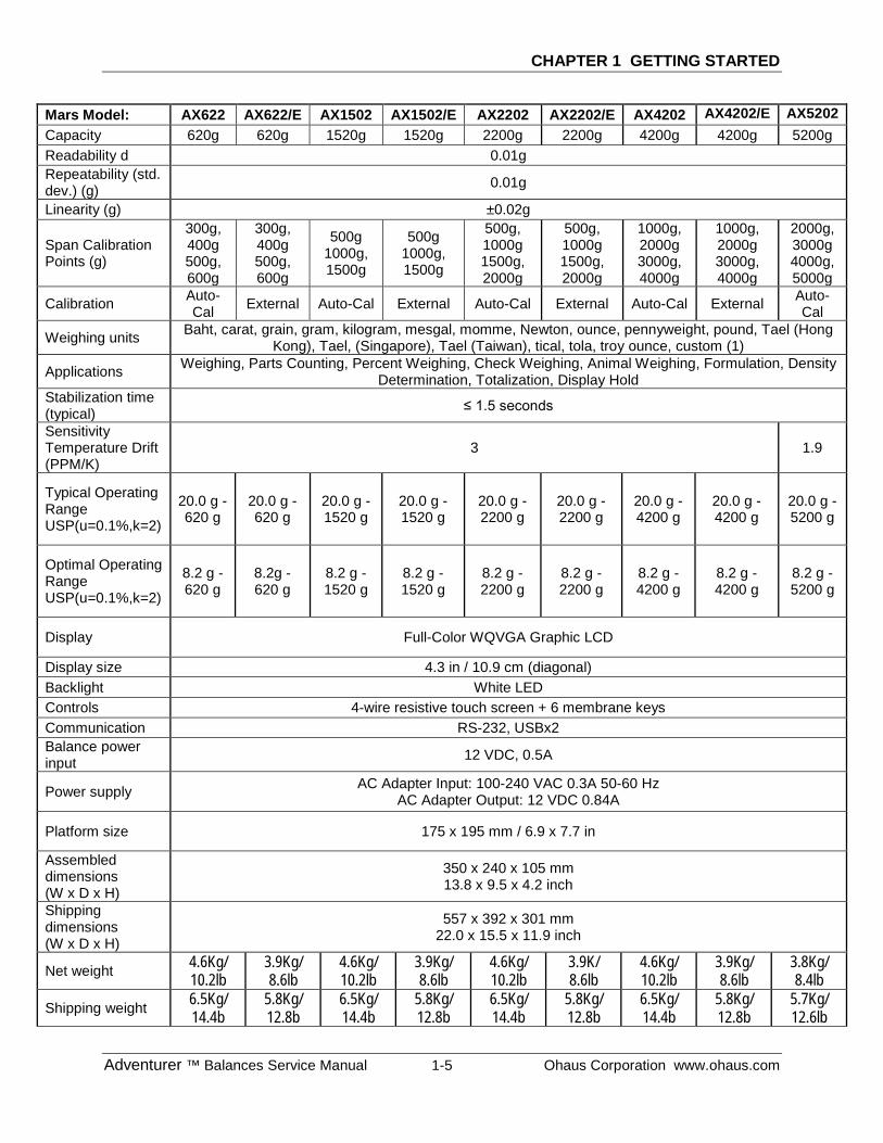
Mars Model: AX622 AX622/E AX1502 AX1502/E AX2202 AX2202/E AX4202 AX4202/E AX5202 Capacity 620g 620g 1520g 1520g 2200g 2200g 4200g 4200g 5200g Readability d 0.01g Repeatability (std. dev.) (g) 0.01g
Linearity (g) ±0.02g
Span Calibration Points (g)
300g, 400g 500g, 600g
300g, 400g 500g, 600g
500g 1000g, 1500g
500g 1000g, 1500g
500g, 1000g 1500g, 2000g
500g, 1000g 1500g, 2000g
1000g, 2000g 3000g, 4000g
1000g, 2000g 3000g, 4000g
2000g, 3000g 4000g, 5000g
Calibration Auto-Cal External Auto-Cal External Auto-Cal External Auto-Cal External Auto-
Cal
Weighing units Baht, carat, grain, gram, kilogram, mesgal, momme, Newton, ounce, pennyweight, pound, Tael (Hong Kong), Tael, (Singapore), Tael (Taiwan), tical, tola, troy ounce, custom (1)
Applications Weighing, Parts Counting, Percent Weighing, Check Weighing, Animal Weighing, Formulation, Density Determination, Totalization, Display Hold
Stabilization time (typical) ≤ 1.5 seconds
Sensitivity Temperature Drift (PPM/K)
3 1.9
Typical Operating Range USP(u=0.1%,k=2)
20.0 g -620 g
20.0 g -620 g
20.0 g -1520 g
20.0 g -1520 g
20.0 g -2200 g
20.0 g -2200 g
20.0 g -4200 g
20.0 g -4200 g
20.0 g -5200 g
Optimal Operating Range USP(u=0.1%,k=2)
8.2 g -620 g
8.2g -620 g
8.2 g -1520 g
8.2 g -1520 g
8.2 g -2200 g
8.2 g -2200 g
8.2 g -4200 g
8.2 g -4200 g
8.2 g -5200 g
Display Full-Color WQVGA Graphic LCD
Display size 4.3 in / 10.9 cm (diagonal) Backlight White LED Controls 4-wire resistive touch screen + 6 membrane keys Communication RS-232, USBx2 Balance power input 12 VDC, 0.5A
Power supply AC Adapter Input: 100-240 VAC 0.3A 50-60 Hz AC Adapter Output: 12 VDC 0.84A
Platform size 175 x 195 mm / 6.9 x 7.7 in
Assembled dimensions (W x D x H)
350 x 240 x 105 mm 13.8 x 9.5 x 4.2 inch
Shipping dimensions (W x D x H)
557 x 392 x 301 mm 22.0 x 15.5 x 11.9 inch
Net weight 4.6Kg/ 10.2lb
3.9Kg/ 8.6lb
4.6Kg/ 10.2lb
3.9Kg/ 8.6lb
4.6Kg/ 10.2lb
3.9K/ 8.6lb
4.6Kg/ 10.2lb
3.9Kg/ 8.6lb
3.8Kg/ 8.4lb
Shipping weight 6.5Kg/ 14.4b
5.8Kg/ 12.8b
6.5Kg/ 14.4b
5.8Kg/ 12.8b
6.5Kg/ 14.4b
5.8Kg/ 12.8b
6.5Kg/ 14.4b
5.8Kg/ 12.8b
5.7Kg/ 12.6lb
CHAPTER 1 GETTING STARTED
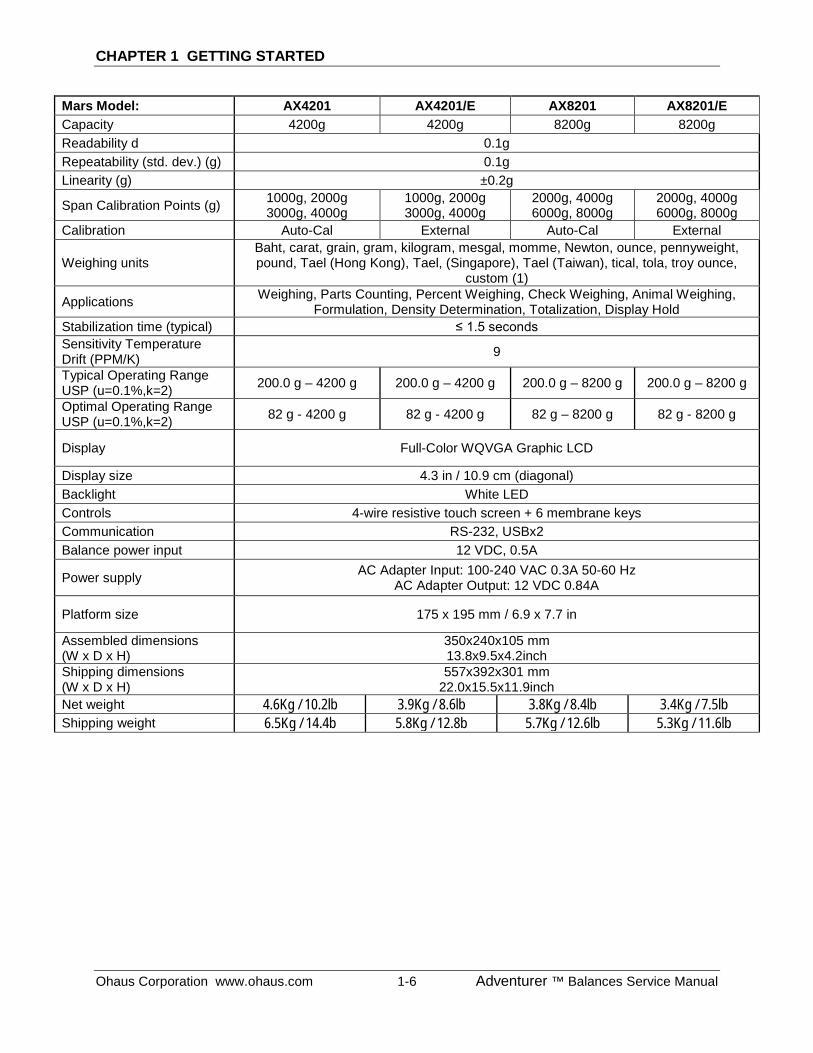
Ohaus Corporation www.ohaus.com 1-6 Adventurer ™ Balances Service Manual
Mars Model: AX4201 AX4201/E AX8201 AX8201/E Capacity 4200g 4200g 8200g 8200g Readability d 0.1g Repeatability (std. dev.) (g) 0.1g Linearity (g) ±0.2g
Span Calibration Points (g) 1000g, 2000g 3000g, 4000g
1000g, 2000g 3000g, 4000g
2000g, 4000g 6000g, 8000g
2000g, 4000g 6000g, 8000g
Calibration Auto-Cal External Auto-Cal External
Weighing units Baht, carat, grain, gram, kilogram, mesgal, momme, Newton, ounce, pennyweight, pound, Tael (Hong Kong), Tael, (Singapore), Tael (Taiwan), tical, tola, troy ounce,
custom (1)
Applications Weighing, Parts Counting, Percent Weighing, Check Weighing, Animal Weighing, Formulation, Density Determination, Totalization, Display Hold
Stabilization time (typical) ≤ 1.5 seconds Sensitivity Temperature Drift (PPM/K) 9
Typical Operating Range USP (u=0.1%,k=2) 200.0 g – 4200 g 200.0 g – 4200 g 200.0 g – 8200 g 200.0 g – 8200 g
Optimal Operating Range USP (u=0.1%,k=2) 82 g - 4200 g 82 g - 4200 g 82 g – 8200 g 82 g - 8200 g
Display Full-Color WQVGA Graphic LCD
Display size 4.3 in / 10.9 cm (diagonal) Backlight White LED Controls 4-wire resistive touch screen + 6 membrane keys Communication RS-232, USBx2 Balance power input 12 VDC, 0.5A
Power supply AC Adapter Input: 100-240 VAC 0.3A 50-60 Hz AC Adapter Output: 12 VDC 0.84A
Platform size 175 x 195 mm / 6.9 x 7.7 in
Assembled dimensions (W x D x H)
350x240x105 mm 13.8x9.5x4.2inch
Shipping dimensions (W x D x H)
557x392x301 mm 22.0x15.5x11.9inch
Net weight 4.6Kg / 10.2lb 3.9Kg / 8.6lb 3.8Kg / 8.4lb 3.4Kg / 7.5lb Shipping weight 6.5Kg / 14.4b 5.8Kg / 12.8b 5.7Kg / 12.6lb 5.3Kg / 11.6lb
CHAPTER 1 GETTING STARTED
Adventurer ™ Balances Service Manual 1-7 Ohaus Corporation www.ohaus.com
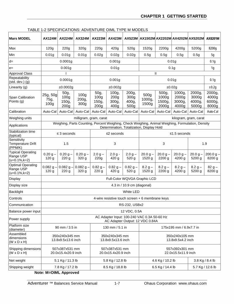
TABLE 1-2 SPECIFICATIONS: ADVENTURE OIML TYPE M MODELS
Mars MODEL AX124M AX224M AX324M AX223M AX423M AX523M AX1502M AX2202M AX4202M AX5202M AX8201M
Max 120g 220g 320g 220g 420g 520g 1520g 2200g 4200g 5200g 8200g
Min 0.01g 0.01g 0.01g 0.02g 0.02g 0.02g 0.5g 0.5g 0.5g 0.5g 5g
d= 0.0001g 0.001g 0.01g 0.1g
e= 0.001g 0.01g 0.1g 1g Approval Class I II Repeatability (std. dev.) (g) 0.0001g 0.001g 0.01g 0.1g
Linearity (g) ±0.0002g ±0.002g ±0.02g ±0.2g
Span Calibration Points (g)
25g, 50g 75g, 100g
50g, 100g 150g, 200g
100g 200g, 300g
50g, 100g 150g, 200g
100g, 200g 300g, 400g
200g, 300g 400g, 500g
500g 1000g, 1500g
500g, 1000g 1500g, 2000g
1000g, 2000g 3000g, 4000g
2000g, 3000g 4000g, 5000g
2000g, 4000g 6000g, 8000g
Calibration Auto-Cal Auto-Cal Auto-Cal Auto-Cal Auto-Cal Auto-Cal Auto-Cal Auto-Cal Auto-Cal Auto-Cal Auto-Cal
Weighing units milligram, gram, carat kilogram, gram, carat
Applications Weighing, Parts Counting, Percent Weighing, Check Weighing, Animal Weighing, Formulation, Density Determination, Totalization, Display Hold
Stabilization time (typical) ≤ 3 seconds ≤2 seconds ≤1.5 seconds
Sensitivity Temperature Drift (PPM/K)
1.5 3 3 1.9
Typical Operating Range USP (u=0.1%,k=2)
0.20 g – 120 g
0.20 g – 220 g
0.20 g – 320 g
2.0 g – 220g
2.0 g - 420 g
2.0 g – 520 g
20.0 g – 1520 g
20.0 g – 2200 g
20.0 g – 4200 g
20.0 g – 5200 g
200.0 g – 8200 g
Optimal Operating Range USP (u=0.1%,k=2)
0.082 g – 120 g
0.082 g – 220 g
0.082 g – 320 g
0.82 g – 220 g
0.82 g – 420 g
0.82 g – 520 g
8.2 g – 1520 g
8.2 g – 2200 g
8.2 g – 4200 g
8.2 g – 5200 g
82 g – 8200 g
Display Full-Color WQVGA Graphic LCD
Display size 4.3 in / 10.9 cm (diagonal)
Backlight White LED
Controls 4-wire resistive touch screen + 6 membrane keys
Communication RS-232, USBx2
Balance power input 12 VDC, 0.5A
Power supply AC Adapter Input: 100-240 VAC 0.3A 50-60 Hz AC Adapter Output: 12 VDC 0.84A
Platform size (diameter) 90 mm / 3.5 in 130 mm / 5.1 in 175x195 mm / 6.9x7.7 in
Assembled dimensions (W x D x H)
350x240x345 mm 13.8x9.5x13.6 inch
350x240x345 mm 13.8x9.5x13.6 inch
350x240x105 mm 13.8x9.5x4.2 inch
Shipping dimensions (W x D x H)
507x387x531 mm 20.0x15.4x20.9 inch
507x387x531 mm 20.0x15.4x20.9 inch
557x392x301 mm 22.0x15.5x11.9 inch
Net weight 5.1 Kg / 11.3 lb 5.8 Kg / 12.8 lb 4.6 Kg / 10.2 lb 3.8 Kg / 8.4 lb
Shipping weight 7.8 Kg / 17.2 lb 8.5 Kg / 18.8 lb 6.5 Kg / 14.4 lb 5.7 Kg / 12.6 lb Note: M=OIML Approved
CHAPTER 1 GETTING STARTED
Ohaus Corporation www.ohaus.com 1-8 Adventurer ™ Balances Service Manual
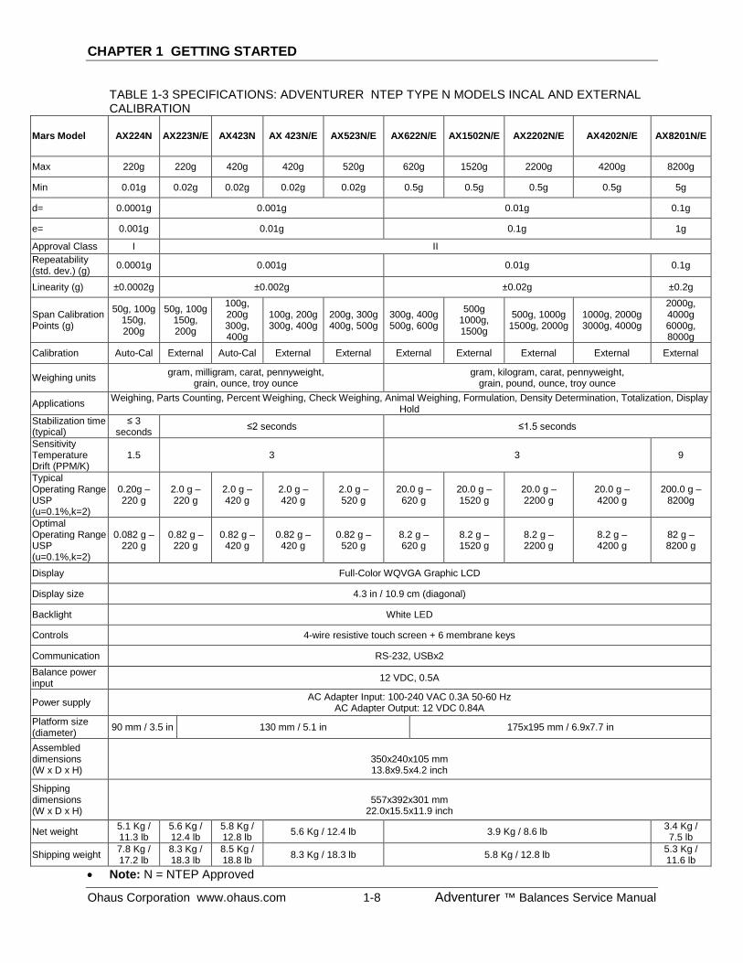
TABLE 1-3 SPECIFICATIONS: ADVENTURER NTEP TYPE N MODELS INCAL AND EXTERNAL CALIBRATION
Mars Model AX224N AX223N/E AX423N AX 423N/E AX523N/E AX622N/E AX1502N/E AX2202N/E AX4202N/E AX8201N/E
Max 220g 220g 420g 420g 520g 620g 1520g 2200g 4200g 8200g
Min 0.01g 0.02g 0.02g 0.02g 0.02g 0.5g 0.5g 0.5g 0.5g 5g
d= 0.0001g 0.001g 0.01g 0.1g
e= 0.001g 0.01g 0.1g 1g
Approval Class I II Repeatability (std. dev.) (g) 0.0001g 0.001g 0.01g 0.1g
Linearity (g) ±0.0002g ±0.002g ±0.02g ±0.2g
Span Calibration Points (g)
50g, 100g 150g, 200g
50g, 100g 150g, 200g
100g, 200g 300g, 400g
100g, 200g 300g, 400g
200g, 300g 400g, 500g
300g, 400g 500g, 600g
500g 1000g, 1500g
500g, 1000g 1500g, 2000g
1000g, 2000g 3000g, 4000g
2000g, 4000g 6000g, 8000g
Calibration Auto-Cal External Auto-Cal External External External External External External External
Weighing units gram, milligram, carat, pennyweight, grain, ounce, troy ounce
gram, kilogram, carat, pennyweight, grain, pound, ounce, troy ounce
Applications Weighing, Parts Counting, Percent Weighing, Check Weighing, Animal Weighing, Formulation, Density Determination, Totalization, Display Hold
Stabilization time (typical)
≤ 3 seconds ≤2 seconds ≤1.5 seconds
Sensitivity Temperature Drift (PPM/K)
1.5 3 3 9
Typical Operating Range USP (u=0.1%,k=2)
0.20g – 220 g
2.0 g – 220 g
2.0 g – 420 g
2.0 g – 420 g
2.0 g – 520 g
20.0 g – 620 g
20.0 g – 1520 g
20.0 g – 2200 g
20.0 g – 4200 g
200.0 g – 8200g
Optimal Operating Range USP (u=0.1%,k=2)
0.082 g – 220 g
0.82 g – 220 g
0.82 g – 420 g
0.82 g – 420 g
0.82 g – 520 g
8.2 g – 620 g
8.2 g – 1520 g
8.2 g – 2200 g
8.2 g – 4200 g
82 g – 8200 g
Display Full-Color WQVGA Graphic LCD
Display size 4.3 in / 10.9 cm (diagonal)
Backlight White LED
Controls 4-wire resistive touch screen + 6 membrane keys
Communication RS-232, USBx2 Balance power input 12 VDC, 0.5A
Power supply AC Adapter Input: 100-240 VAC 0.3A 50-60 Hz AC Adapter Output: 12 VDC 0.84A
Platform size (diameter) 90 mm / 3.5 in 130 mm / 5.1 in 175x195 mm / 6.9x7.7 in
Assembled dimensions (W x D x H)
350x240x105 mm 13.8x9.5x4.2 inch
Shipping dimensions (W x D x H)
557x392x301 mm
22.0x15.5x11.9 inch
Net weight 5.1 Kg / 11.3 lb
5.6 Kg / 12.4 lb
5.8 Kg / 12.8 lb 5.6 Kg / 12.4 lb 3.9 Kg / 8.6 lb 3.4 Kg /
7.5 lb
Shipping weight 7.8 Kg / 17.2 lb
8.3 Kg / 18.3 lb
8.5 Kg / 18.8 lb 8.3 Kg / 18.3 lb 5.8 Kg / 12.8 lb 5.3 Kg /
11.6 lb • Note: N = NTEP Approved
CHAPTER 1 GETTING STARTED
Adventurer ™ Balances Service Manual 1-9 Ohaus Corporation www.ohaus.com
1.5 ADMISSIBLE AMBIENT CONDITIONS
Ambient conditions • Indoor use only • Altitude: Up to 2000 m • Specified Temperature range: 10°C to 30°C • Humidity: maximum relative humidity 80 % for temperatures up to 30°C
decreasing linearly to 50% relative humidity at 40°C • Mains supply voltage fluctuations: up to ±10% of the nominal voltage • Installation category II • Pollution degree: 2 Materials • Bottom Housing; die-cast Aluminum, Painted • Top Housing: Plastic (ABS) • Weighing Platforms: 18/10 stainless steel • Draft Shield: Glass, plastic (ABS) • Feet: Plastic (ABS)
CHAPTER 1 GETTING STARTED
Ohaus Corporation www.ohaus.com 1-10 Adventurer ™ Balances Service Manual
1.6 BALANCE OPERATION
OPERATION
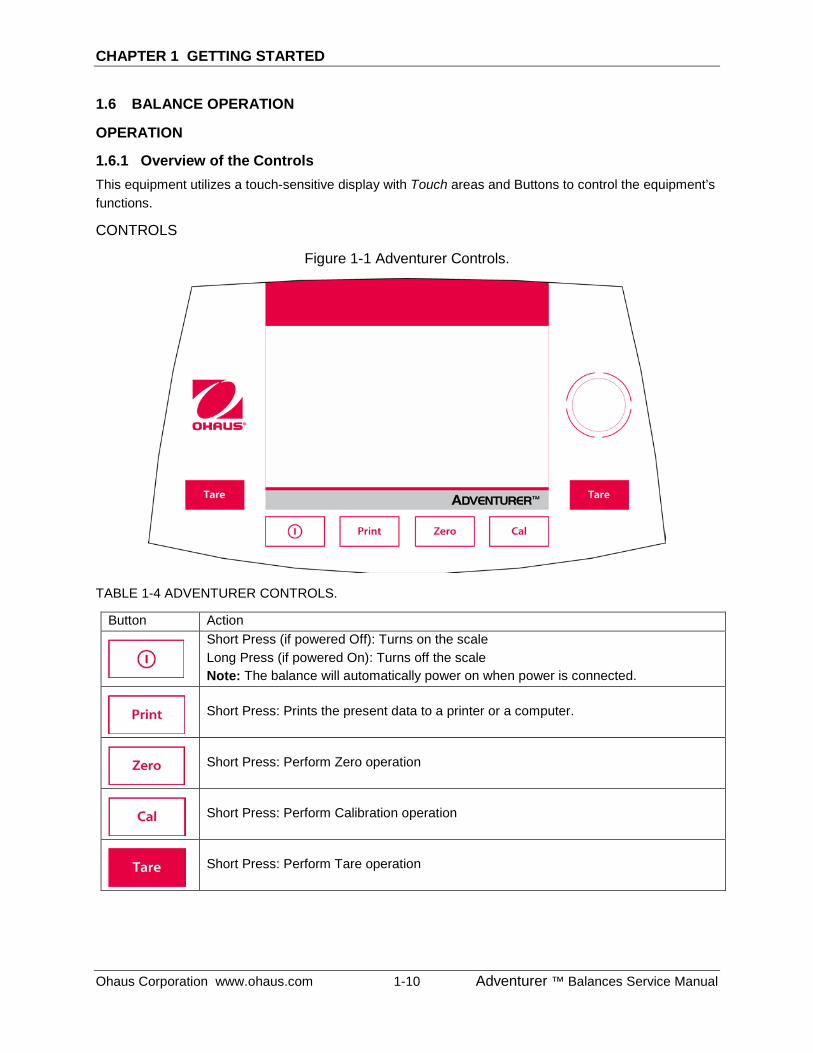
1.6.1 Overview of the Controls This equipment utilizes a touch-sensitive display with Touch areas and Buttons to control the equipment’s functions.
CONTROLS
Figure 1-1 Adventurer Controls.
TABLE 1-4 ADVENTURER CONTROLS.
Button Action
Short Press (if powered Off): Turns on the scale Long Press (if powered On): Turns off the scale Note: The balance will automatically power on when power is connected.
Short Press: Prints the present data to a printer or a computer.
Short Press: Perform Zero operation
Short Press: Perform Calibration operation
Short Press: Perform Tare operation
CHAPTER 1 GETTING STARTED
Adventurer ™ Balances Service Manual 1-11 Ohaus Corporation www.ohaus.com
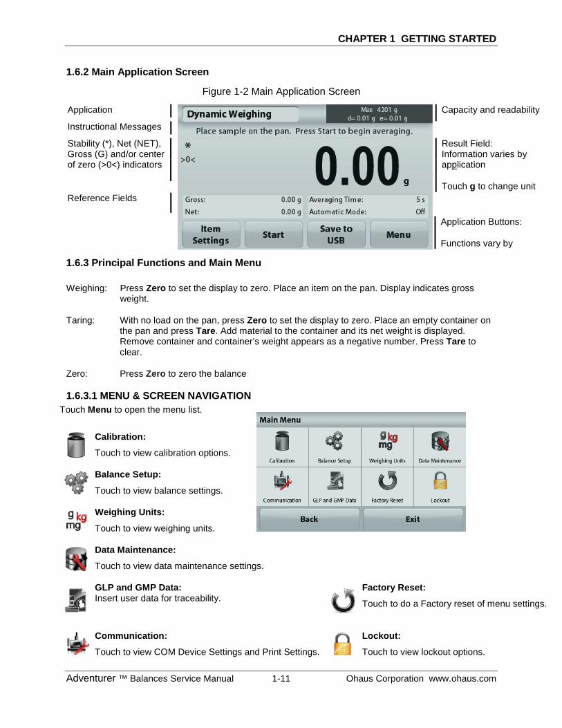
1.6.2 Main Application Screen
Figure 1-2 Main Application Screen
1.6.3 Principal Functions and Main Menu
Weighing: Press Zero to set the display to zero. Place an item on the pan. Display indicates gross weight.
Taring: With no load on the pan, press Zero to set the display to zero. Place an empty container on the pan and press Tare. Add material to the container and its net weight is displayed. Remove container and container’s weight appears as a negative number. Press Tare to clear.
Zero: Press Zero to zero the balance
1.6.3.1 MENU & SCREEN NAVIGATION Touch Menu to open the menu list.
Calibration:
Touch to view calibration options.
Balance Setup:
Touch to view balance settings.
Weighing Units:
Touch to view weighing units.
Data Maintenance:
Touch to view data maintenance settings.
GLP and GMP Data: Insert user data for traceability.
Factory Reset:
Touch to do a Factory reset of menu settings.
Communication:
Touch to view COM Device Settings and Print Settings.
Lockout:
Touch to view lockout options.
Application
Instructional Messages
Stability (*), Net (NET), Gross (G) and/or center of zero (>0<) indicators
Reference Fields
Application Buttons:
Functions vary by
Result Field: Information varies by application
Touch g to change unit
Capacity and readability
CHAPTER 1 GETTING STARTED
Ohaus Corporation www.ohaus.com 1-12 Adventurer ™ Balances Service Manual
1.7 The Load Cell
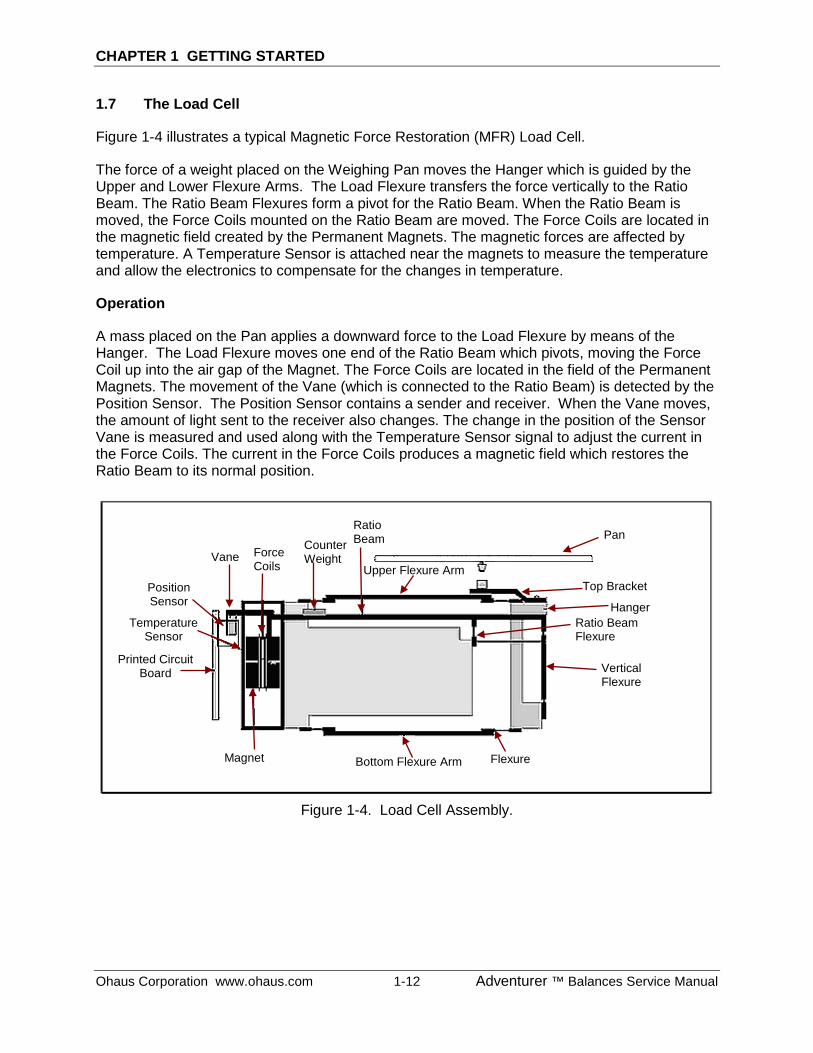
Figure 1-4 illustrates a typical Magnetic Force Restoration (MFR) Load Cell.
The force of a weight placed on the Weighing Pan moves the Hanger which is guided by the Upper and Lower Flexure Arms. The Load Flexure transfers the force vertically to the Ratio Beam. The Ratio Beam Flexures form a pivot for the Ratio Beam. When the Ratio Beam is moved, the Force Coils mounted on the Ratio Beam are moved. The Force Coils are located in the magnetic field created by the Permanent Magnets. The magnetic forces are affected by temperature. A Temperature Sensor is attached near the magnets to measure the temperature and allow the electronics to compensate for the changes in temperature.
Operation
A mass placed on the Pan applies a downward force to the Load Flexure by means of the Hanger. The Load Flexure moves one end of the Ratio Beam which pivots, moving the Force Coil up into the air gap of the Magnet. The Force Coils are located in the field of the Permanent Magnets. The movement of the Vane (which is connected to the Ratio Beam) is detected by the Position Sensor. The Position Sensor contains a sender and receiver. When the Vane moves, the amount of light sent to the receiver also changes. The change in the position of the Sensor Vane is measured and used along with the Temperature Sensor signal to adjust the current in the Force Coils. The current in the Force Coils produces a magnetic field which restores the Ratio Beam to its normal position.
Figure 1-4. Load Cell Assembly.
Ratio Beam Flexure
Vertical Flexure
Top Bracket
Hanger
Bottom Flexure Arm Flexure Magnet
Printed Circuit Board
Temperature Sensor
Position Sensor
Vane Force Coils
Ratio Beam Counter
Weight Upper Flexure Arm
Pan
CHAPTER 1 GETTING STARTED
Adventurer ™ Balances Service Manual 1-13 Ohaus Corporation www.ohaus.com
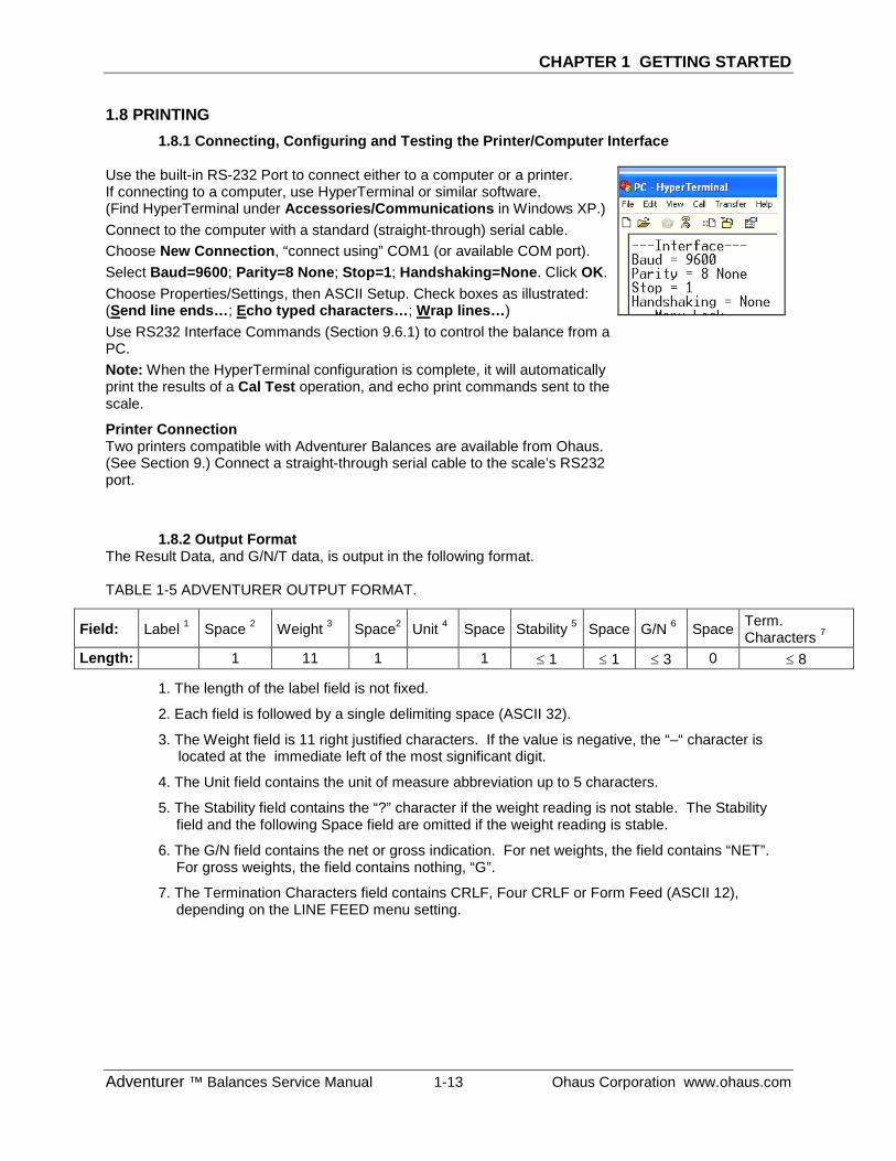
1.8 PRINTING 1.8.1 Connecting, Configuring and Testing the Printer/Computer Interface
Use the built-in RS-232 Port to connect either to a computer or a printer. If connecting to a computer, use HyperTerminal or similar software. (Find HyperTerminal under Accessories/Communications in Windows XP.) Connect to the computer with a standard (straight-through) serial cable. Choose New Connection, “connect using” COM1 (or available COM port). Select Baud=9600; Parity=8 None; Stop=1; Handshaking=None. Click OK. Choose Properties/Settings, then ASCII Setup. Check boxes as illustrated: (Send line ends…; Echo typed characters…; Wrap lines…) Use RS232 Interface Commands (Section 9.6.1) to control the balance from a PC. Note: When the HyperTerminal configuration is complete, it will automatically print the results of a Cal Test operation, and echo print commands sent to the scale.
Printer Connection Two printers compatible with Adventurer Balances are available from Ohaus. (See Section 9.) Connect a straight-through serial cable to the scale’s RS232 port.
1.8.2 Output Format The Result Data, and G/N/T data, is output in the following format. TABLE 1-5 ADVENTURER OUTPUT FORMAT.
Field: Label 1 Space 2 Weight 3 Space2 Unit 4 Space Stability 5 Space G/N 6 Space Term. Characters 7
Length: 1 11 1 1 ≤ 1 ≤ 1 ≤ 3 0 ≤ 8
1. The length of the label field is not fixed.
2. Each field is followed by a single delimiting space (ASCII 32).
3. The Weight field is 11 right justified characters. If the value is negative, the “–“ character is located at the immediate left of the most significant digit.
4. The Unit field contains the unit of measure abbreviation up to 5 characters.
5. The Stability field contains the “?” character if the weight reading is not stable. The Stability field and the following Space field are omitted if the weight reading is stable.
6. The G/N field contains the net or gross indication. For net weights, the field contains “NET”. For gross weights, the field contains nothing, “G”.
7. The Termination Characters field contains CRLF, Four CRLF or Form Feed (ASCII 12), depending on the LINE FEED menu setting.
CHAPTER 1 GETTING STARTED
Ohaus Corporation www.ohaus.com 1-14 Adventurer ™ Balances Service Manual
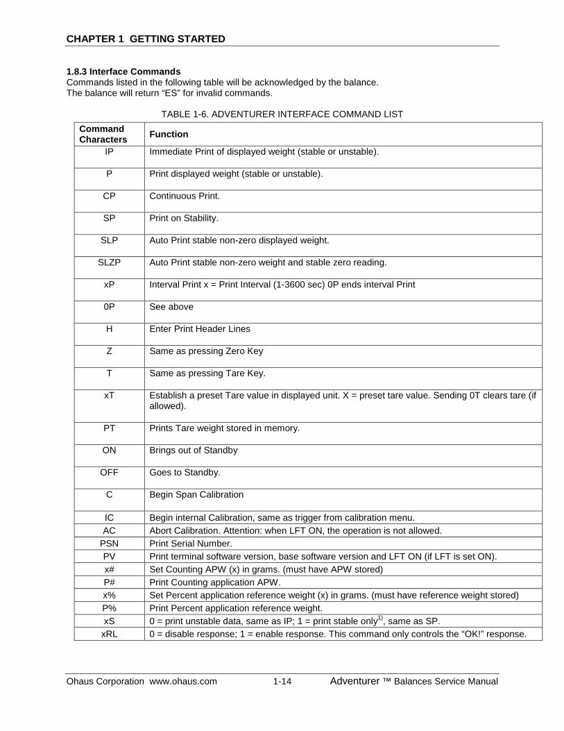
1.8.3 Interface Commands Commands listed in the following table will be acknowledged by the balance. The balance will return “ES” for invalid commands.
TABLE 1-6. ADVENTURER INTERFACE COMMAND LIST Command Characters Function
IP Immediate Print of displayed weight (stable or unstable).
P Print displayed weight (stable or unstable).
CP Continuous Print.
SP Print on Stability.
SLP Auto Print stable non-zero displayed weight.
SLZP Auto Print stable non-zero weight and stable zero reading.
xP Interval Print x = Print Interval (1-3600 sec) 0P ends interval Print
0P See above
H Enter Print Header Lines
Z Same as pressing Zero Key
T Same as pressing Tare Key.
xT Establish a preset Tare value in displayed unit. X = preset tare value. Sending 0T clears tare (if allowed).
PT Prints Tare weight stored in memory.
ON Brings out of Standby
OFF Goes to Standby.
C Begin Span Calibration
IC Begin internal Calibration, same as trigger from calibration menu. AC Abort Calibration. Attention: when LFT ON, the operation is not allowed.
PSN Print Serial Number. PV Print terminal software version, base software version and LFT ON (if LFT is set ON). x# Set Counting APW (x) in grams. (must have APW stored) P# Print Counting application APW. x% Set Percent application reference weight (x) in grams. (must have reference weight stored) P% Print Percent application reference weight. xS 0 = print unstable data, same as IP; 1 = print stable only1), same as SP.
xRL 0 = disable response; 1 = enable response. This command only controls the “OK!” response.
CHAPTER 1 GETTING STARTED
Adventurer ™ Balances Service Manual 1-15 Ohaus Corporation www.ohaus.com
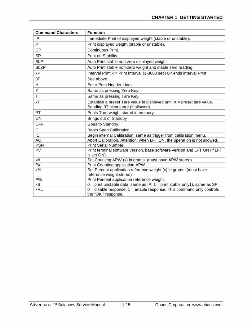
Command Characters Function IP Immediate Print of displayed weight (stable or unstable). P Print displayed weight (stable or unstable). CP Continuous Print. SP Print on Stability. SLP Auto Print stable non-zero displayed weight. SLZP Auto Print stable non-zero weight and stable zero reading. xP Interval Print x = Print Interval (1-3600 sec) 0P ends interval Print 0P See above H Enter Print Header Lines Z Same as pressing Zero Key T Same as pressing Tare Key. xT Establish a preset Tare value in displayed unit. X = preset tare value.
Sending 0T clears tare (if allowed). PT Prints Tare weight stored in memory. ON Brings out of Standby OFF Goes to Standby. C Begin Span Calibration IC Begin internal Calibration, same as trigger from calibration menu. AC Abort Calibration. Attention: when LFT ON, the operation is not allowed. PSN Print Serial Number. PV Print terminal software version, base software version and LFT ON (if LFT
is set ON). x# Set Counting APW (x) in grams. (must have APW stored) P# Print Counting application APW. x% Set Percent application reference weight (x) in grams. (must have
reference weight stored) P% Print Percent application reference weight. xS 0 = print unstable data, same as IP; 1 = print stable only1), same as SP. xRL 0 = disable response; 1 = enable response. This command only controls
the “OK!” response.
CHAPTER 1 GETTING STARTED
Ohaus Corporation www.ohaus.com 1-16 Adventurer ™ Balances Service Manual
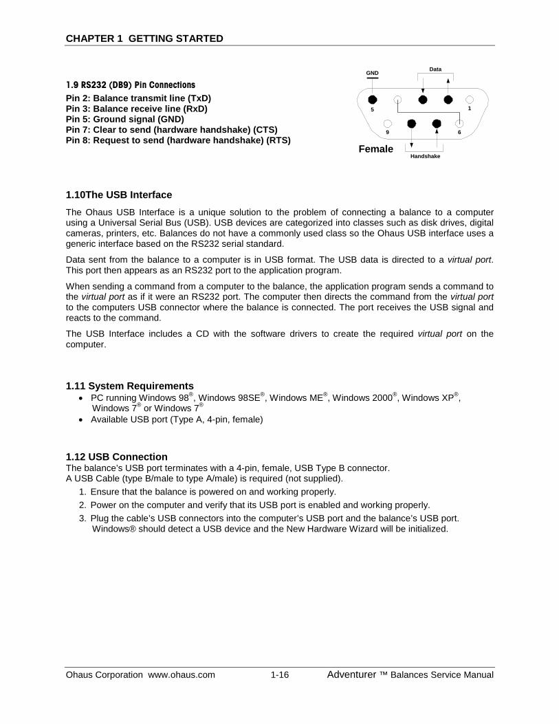
1.9 RS232 (DB9) Pin Connections Pin 2: Balance transmit line (TxD) Pin 3: Balance receive line (RxD) Pin 5: Ground signal (GND) Pin 7: Clear to send (hardware handshake) (CTS) Pin 8: Request to send (hardware handshake) (RTS)
1.10The USB Interface
The Ohaus USB Interface is a unique solution to the problem of connecting a balance to a computer using a Universal Serial Bus (USB). USB devices are categorized into classes such as disk drives, digital cameras, printers, etc. Balances do not have a commonly used class so the Ohaus USB interface uses a generic interface based on the RS232 serial standard.
Data sent from the balance to a computer is in USB format. The USB data is directed to a virtual port. This port then appears as an RS232 port to the application program.
When sending a command from a computer to the balance, the application program sends a command to the virtual port as if it were an RS232 port. The computer then directs the command from the virtual port to the computers USB connector where the balance is connected. The port receives the USB signal and reacts to the command.
The USB Interface includes a CD with the software drivers to create the required virtual port on the computer. 1.11 System Requirements
• PC running Windows 98®, Windows 98SE®, Windows ME®, Windows 2000®, Windows XP®, Windows 7® or Windows 7®
• Available USB port (Type A, 4-pin, female)
1.12 USB Connection The balance’s USB port terminates with a 4-pin, female, USB Type B connector. A USB Cable (type B/male to type A/male) is required (not supplied).
1. Ensure that the balance is powered on and working properly. 2. Power on the computer and verify that its USB port is enabled and working properly. 3. Plug the cable’s USB connectors into the computer’s USB port and the balance’s USB port.
Windows® should detect a USB device and the New Hardware Wizard will be initialized.
15
69
DataGND
HandshakeFemale
CHAPTER 1 GETTING STARTED
Adventurer ™ Balances Service Manual 1-17 Ohaus Corporation www.ohaus.com
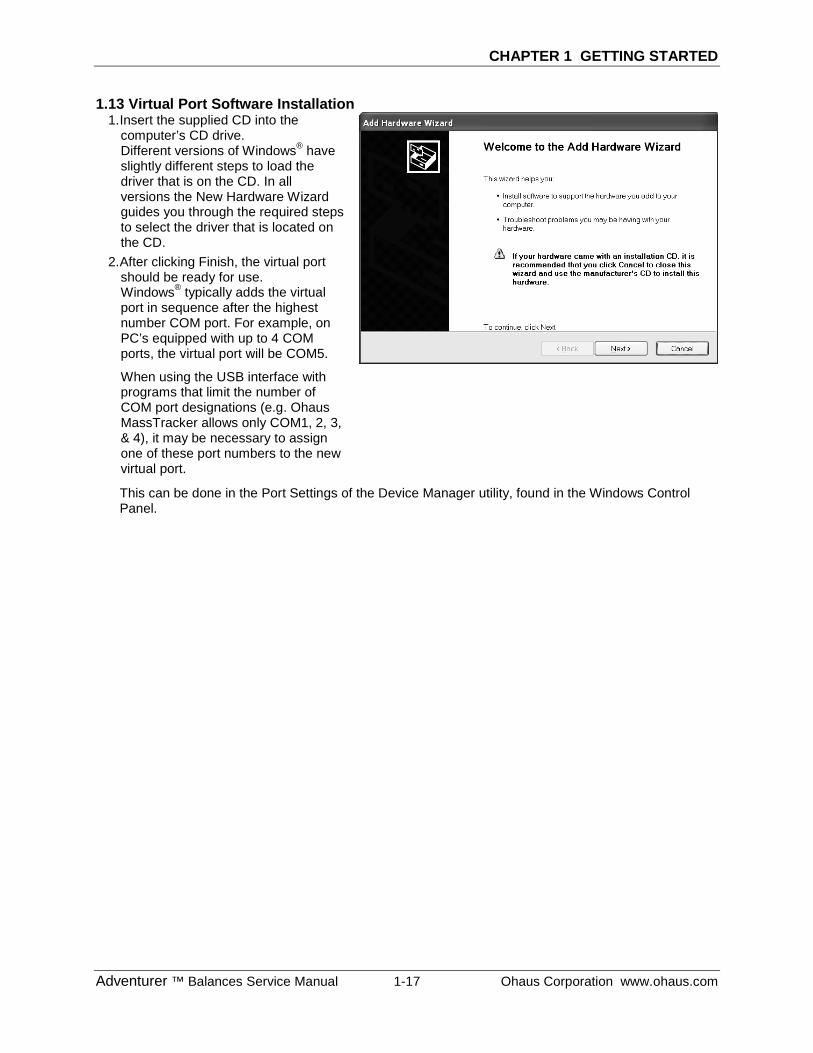
1.13 Virtual Port Software Installation 1. Insert the supplied CD into the
computer’s CD drive. Different versions of Windows® have slightly different steps to load the driver that is on the CD. In all versions the New Hardware Wizard guides you through the required steps to select the driver that is located on the CD.
2. After clicking Finish, the virtual port should be ready for use. Windows® typically adds the virtual port in sequence after the highest number COM port. For example, on PC’s equipped with up to 4 COM ports, the virtual port will be COM5.
When using the USB interface with programs that limit the number of COM port designations (e.g. Ohaus MassTracker allows only COM1, 2, 3, & 4), it may be necessary to assign one of these port numbers to the new virtual port.
This can be done in the Port Settings of the Device Manager utility, found in the Windows Control Panel.
CHAPTER 1 GETTING STARTED
Ohaus Corporation www.ohaus.com 1-18 Adventurer ™ Balances Service Manual
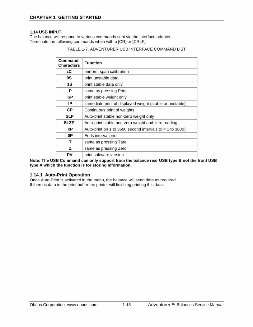
1.14 USB INPUT The balance will respond to various commands sent via the interface adapter. Terminate the following commands when with a [CR] or [CRLF].
TABLE 1-7. ADVENTURER USB INTERFACE COMMAND LIST
Command Characters Function
zC perform span calibration 0S print unstable data 1S print stable data only P same as pressing Print
SP print stable weight only IP immediate print of displayed weight (stable or unstable) CP Continuous print of weights SLP Auto-print stable non-zero weight only SLZP Auto-print stable non-zero weight and zero reading xP Auto-print on 1 to 3600 second intervals (x = 1 to 3600) 0P Ends interval print T same as pressing Tare Z same as pressing Zero PV print software version
Note: The USB Command can only support from the balance rear USB type B not the front USB type A which the function is for storing information. 1.14.1 Auto-Print Operation Once Auto-Print is activated in the menu, the balance will send data as required. If there is data in the print buffer the printer will finishing printing this data.
CHAPTER 2 DIAGNOSTIC GUIDE
Adventurer™ Balance Service Manual 2-1 Ohaus Corporation www.ohaus.com
2.1 TROUBLESHOOTING
This section of the manual provides guidelines for evaluating the condition and performance of a balance, and a standard troubleshooting methodology to follow. Follow all directions step by step. Make certain that the work area is clean. Handle balance components with care. Use an appropriate Electro-Static Device.
2.1.1 General Procedures for Troubleshooting
1. Do the most obvious, user-level remedies.
2. Perform Ramp check and Service Calibration.
3. Check that internal parts are clean and free of debris.
4. Inspect the motion of the Ratio Beam: it should move up and down freely. If not, determine if the cause is mechanical binding, or electrical malfunction.
5. Make an electrical check of the Ratio Beam: measure the resistance of the coils in the Ratio Beam.
6. Check the InCal Mechanism (if applicable). It should move up and down smoothly.
7. Inspect the Load Cell components. Be sure they are clean and that no Flexures are bent. (If they are, they must be replaced.)
2.2 DIAGNOSTIC GUIDE
Table 2-1 is a Diagnostic Guide designed to help locate the problem area quickly and easily. The probable causes are listed with the most common cause first. If the first remedy does not fix the problem, proceed to the next remedy. Before attempting to repair the balance, read all chapters of this manual to be familiar with the balance components and operation.
2.2.1 Diagnosis
1. Isolate and identify the symptom
2. Refer to Table 2-1, Diagnostic Guide and locate the symptom.
3. Follow the suggested remedies in the order they appear.
4. Perform the indicated checks, General Troubleshooting Procedures, or see the appropriate section of the manual.
5. Repair or replace the defective part of the balance.
NOTE: If more than one symptom is observed, approach one area at a time, and remember that the symptoms may be interrelated. If a problem arises that is not covered in this manual, contact Ohaus Corporation for further information.
CHAPTER 2 DIAGNOSTIC GUIDE
Ohaus Corporation www.ohaus.com 2-2 Adventurer ™ Balances Service Manual
2.2.1 Diagnosis
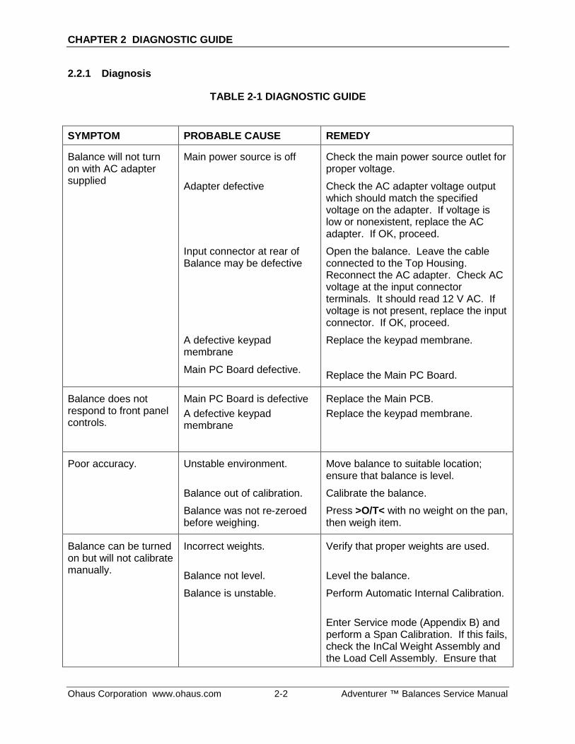
TABLE 2-1 DIAGNOSTIC GUIDE
SYMPTOM PROBABLE CAUSE REMEDY
Balance will not turn on with AC adapter supplied
Main power source is off
Adapter defective
Input connector at rear of Balance may be defective
A defective keypad membrane
Main PC Board defective.
Check the main power source outlet for proper voltage.
Check the AC adapter voltage output which should match the specified voltage on the adapter. If voltage is low or nonexistent, replace the AC adapter. If OK, proceed.
Open the balance. Leave the cable connected to the Top Housing. Reconnect the AC adapter. Check AC voltage at the input connector terminals. It should read 12 V AC. If voltage is not present, replace the input connector. If OK, proceed.
Replace the keypad membrane.
Replace the Main PC Board.
Balance does not respond to front panel controls.
Main PC Board is defective A defective keypad membrane
Replace the Main PCB. Replace the keypad membrane.
Poor accuracy.
Unstable environment.
Balance out of calibration.
Balance was not re-zeroed before weighing.
Move balance to suitable location; ensure that balance is level.
Calibrate the balance.
Press >O/T< with no weight on the pan, then weigh item.
Balance can be turned on but will not calibrate manually.
Incorrect weights.
Balance not level.
Balance is unstable.
Verify that proper weights are used.
Level the balance.
Perform Automatic Internal Calibration.
Enter Service mode (Appendix B) and perform a Span Calibration. If this fails, check the InCal Weight Assembly and the Load Cell Assembly. Ensure that
CHAPTER 2 DIAGNOSTIC GUIDE
Adventurer™ Balance Service Manual 2-3 Ohaus Corporation www.ohaus.com
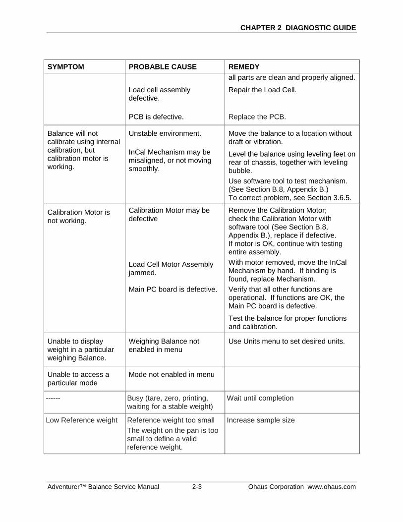
SYMPTOM PROBABLE CAUSE REMEDY
Load cell assembly defective. PCB is defective.
all parts are clean and properly aligned.
Repair the Load Cell. Replace the PCB.
Balance will not calibrate using internal calibration, but calibration motor is working.
Unstable environment. InCal Mechanism may be misaligned, or not moving smoothly.
Move the balance to a location without draft or vibration.
Level the balance using leveling feet on rear of chassis, together with leveling bubble. Use software tool to test mechanism. (See Section B.8, Appendix B.) To correct problem, see Section 3.6.5.
Calibration Motor is not working.
Calibration Motor may be defective
Load Cell Motor Assembly jammed. Main PC board is defective.
Remove the Calibration Motor; check the Calibration Motor with software tool (See Section B.8, Appendix B.), replace if defective. If motor is OK, continue with testing entire assembly. With motor removed, move the InCal Mechanism by hand. If binding is found, replace Mechanism. Verify that all other functions are operational. If functions are OK, the Main PC board is defective.
Test the balance for proper functions and calibration.
Unable to display weight in a particular weighing Balance.
Weighing Balance not enabled in menu
Use Units menu to set desired units.
Unable to access a particular mode
Mode not enabled in menu
------ Busy (tare, zero, printing, waiting for a stable weight)
Wait until completion
Low Reference weight Reference weight too small The weight on the pan is too small to define a valid reference weight.
Increase sample size
CHAPTER 2 DIAGNOSTIC GUIDE
Ohaus Corporation www.ohaus.com 2-4 Adventurer ™ Balances Service Manual
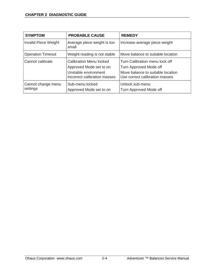
SYMPTOM PROBABLE CAUSE REMEDY
Invalid Piece Weight Average piece weight is too small
Increase average piece weight
Operation Timeout Weight reading is not stable Move balance to suitable location
Cannot calibrate Calibration Menu locked Approved Mode set to on Unstable environment Incorrect calibration masses
Turn Calibration menu lock off Turn Approved Mode off Move balance to suitable location Use correct calibration masses
Cannot change menu settings
Sub-menu locked Approved Mode set to on
Unlock sub-menu Turn Approved Mode off
CHAPTER 3 MAINTENANCE PROCEDURES
Adventurer ™ Balance Service Manual 3-1 Ohaus Corporation www.ohaus.com
3.1 PREVENTIVE MAINTENANCE
Ohaus balances are precision instruments and should be carefully handled, stored in a clean, dry, dust-free area, and cleaned periodically. Follow these precautionary steps:
– When a balance has had chemicals or liquids spilled on it, all exterior surfaces should be cleaned as soon as possible with warm water on a damp cloth.
– Do not leave a mass on the balance when the balance is not in use.
– Allow time for the balance to stabilize after moving it from an area which is at a different temperature than the area where it is to be operated. Allow one hour for each 5° F or 3° C temperature change before using the balance. Following temperature stabilization, allow an additional hour after connecting power to the balance, for the balance to stabilize.
3.1.1 Preventive Maintenance Checklist
The balance should be inspected and checked regularly, as follows:
1. Remove the Pan and Pan Support to inspect and clean the area beneath the Pan.
2. Clean the outside of the balance using a damp cloth with warm water.
CAUTION: DO NOT USE CHEMICAL CLEANERS OR SOLVENTS OF ANY TYPE. SOME CLEANERS ARE ABRASIVE AND MAY AFFECT THE BALANCE’S FINISH.
3. Check the Power Cord for broken or damaged insulation.
4. Make a visual inspection for faulty connectors, wiring, and loose hardware.
3.2 OPENING THE BALANCE
Opening the Adventurer (AX) balance varies slightly according to the specific model, as detailed below. Differences are detailed in the text. Use these procedures in order to:
– Replace Printed Circuit Boards
– Replace bent or broken Flexures
– Gain access to the Load Cell for removal, cleaning, parts replacement and alignment.
CHAPTER 3 MAINTENANCE PROCEDURES
Ohaus Corporation www.ohaus.com 3-2 Adventurer ™ Balances Service Manual
3.2.1 Removing Adventurer Analytical Housing
Turn the balance off and unplug the power cord before you begin.
Preliminary Steps:
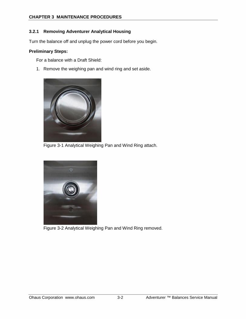
For a balance with a Draft Shield:
1. Remove the weighing pan and wind ring and set aside.
Figure 3-1 Analytical Weighing Pan and Wind Ring attach.
Figure 3-2 Analytical Weighing Pan and Wind Ring removed.
CHAPTER 3 MAINTENANCE PROCEDURES
Adventurer ™ Balance Service Manual 3-3 Ohaus Corporation www.ohaus.com
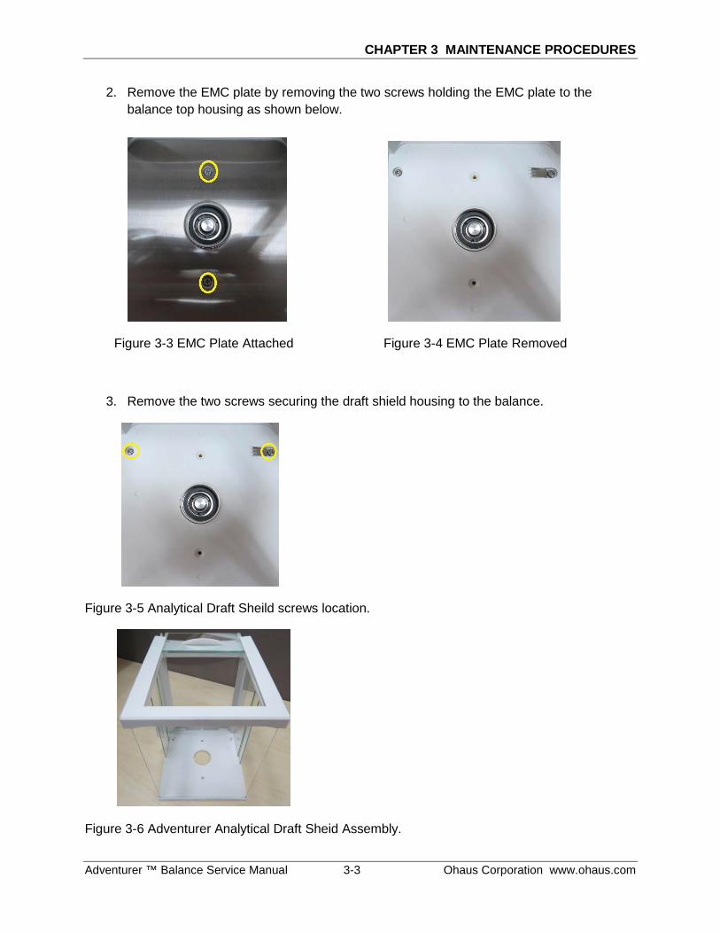
2. Remove the EMC plate by removing the two screws holding the EMC plate to the balance top housing as shown below.
Figure 3-3 EMC Plate Attached Figure 3-4 EMC Plate Removed
3. Remove the two screws securing the draft shield housing to the balance.
Figure 3-5 Analytical Draft Sheild screws location.
Figure 3-6 Adventurer Analytical Draft Sheid Assembly.
CHAPTER 3 MAINTENANCE PROCEDURES
Ohaus Corporation www.ohaus.com 3-4 Adventurer ™ Balances Service Manual
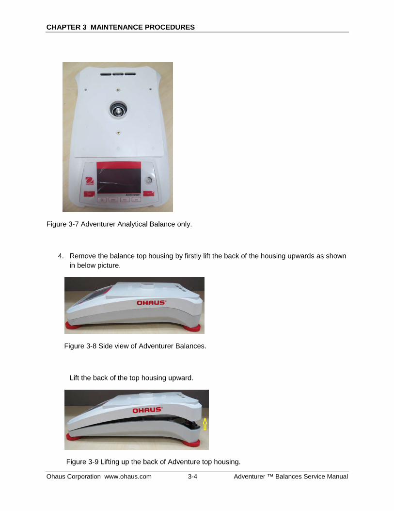
Figure 3-7 Adventurer Analytical Balance only.
4. Remove the balance top housing by firstly lift the back of the housing upwards as shown in below picture.
Figure 3-8 Side view of Adventurer Balances.
Lift the back of the top housing upward.
Figure 3-9 Lifting up the back of Adventure top housing.
CHAPTER 3 MAINTENANCE PROCEDURES
Adventurer ™ Balance Service Manual 3-5 Ohaus Corporation www.ohaus.com
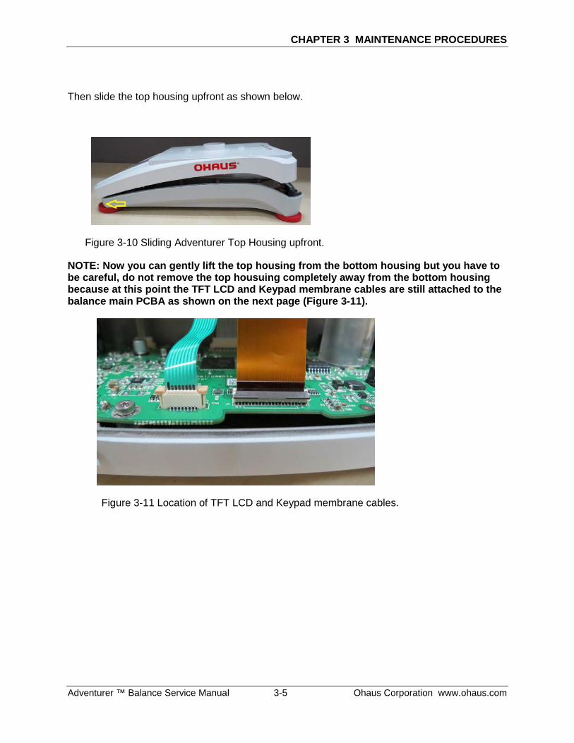
Then slide the top housing upfront as shown below.
Figure 3-10 Sliding Adventurer Top Housing upfront.
NOTE: Now you can gently lift the top housing from the bottom housing but you have to be careful, do not remove the top housuing completely away from the bottom housing because at this point the TFT LCD and Keypad membrane cables are still attached to the balance main PCBA as shown on the next page (Figure 3-11).
Figure 3-11 Location of TFT LCD and Keypad membrane cables.
CHAPTER 3 MAINTENANCE PROCEDURES
Ohaus Corporation www.ohaus.com 3-6 Adventurer ™ Balances Service Manual
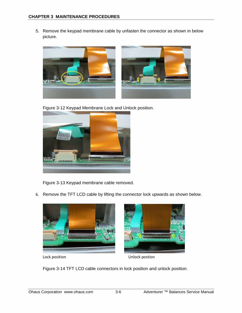
5. Remove the keypad membrane cable by unfasten the connector as shown in below picture.
Figure 3-12 Keypad Membrane Lock and Unlock position.
Figure 3-13 Keypad membrane cable removed.
6. Remove the TFT LCD cable by lifting the connector lock upwards as shown below.
Lock position Unlock postion Figure 3-14 TFT LCD cable connectors in lock position and unlock position.
CHAPTER 3 MAINTENANCE PROCEDURES
Adventurer ™ Balance Service Manual 3-7 Ohaus Corporation www.ohaus.com
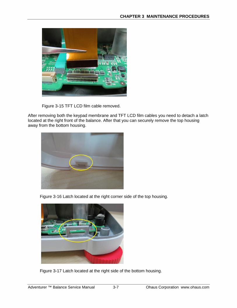
Figure 3-15 TFT LCD film cable removed.
After removing both the keypad membrane and TFT LCD film cables you need to detach a latch located at the right front of the balance. After that you can securely remove the top housing away from the bottom housing.
Figure 3-16 Latch located at the right corner side of the top housing.
Figure 3-17 Latch located at the right side of the bottom housing.
CHAPTER 3 MAINTENANCE PROCEDURES
Ohaus Corporation www.ohaus.com 3-8 Adventurer ™ Balances Service Manual
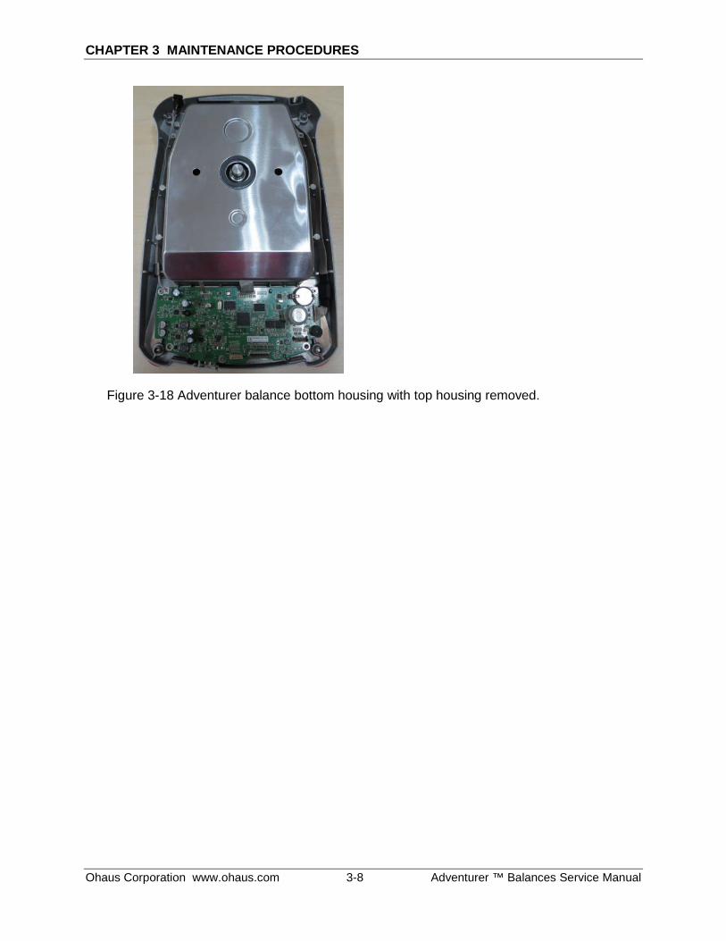
Figure 3-18 Adventurer balance bottom housing with top housing removed.
CHAPTER 3 MAINTENANCE PROCEDURES
Adventurer ™ Balance Service Manual 3-9 Ohaus Corporation www.ohaus.com
3.2.2 Removing Adventurer Precision Housing
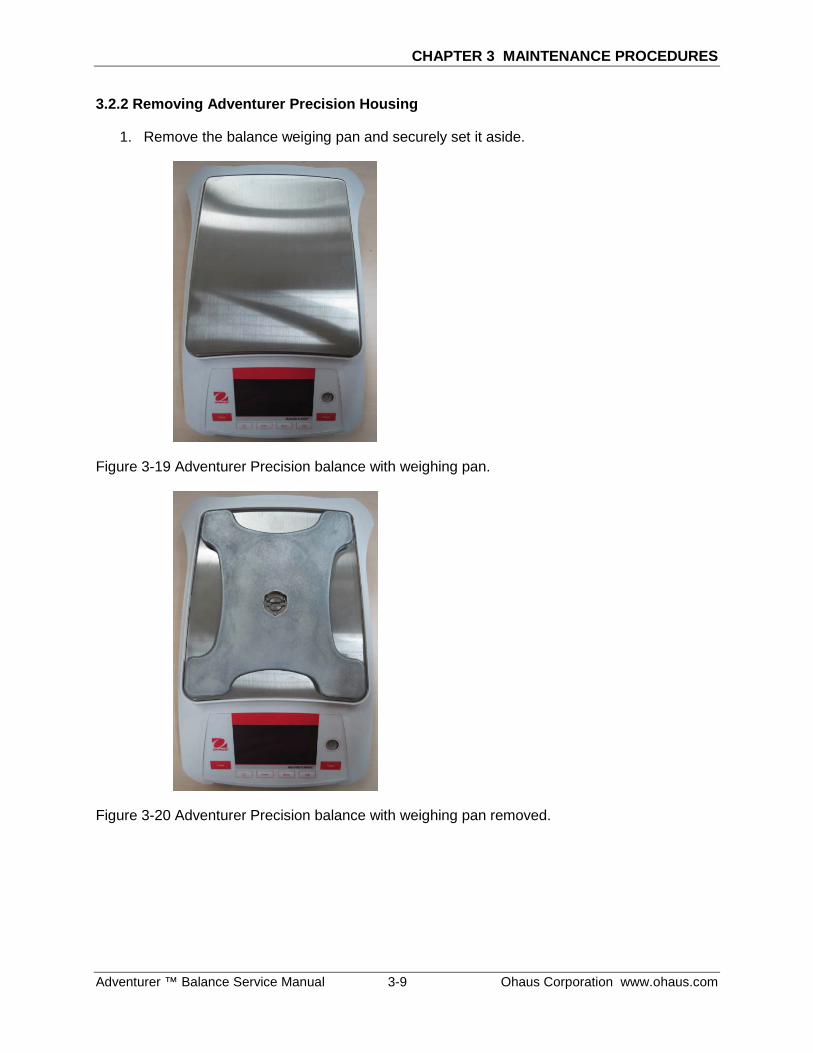
1. Remove the balance weiging pan and securely set it aside.
Figure 3-19 Adventurer Precision balance with weighing pan.
Figure 3-20 Adventurer Precision balance with weighing pan removed.
CHAPTER 3 MAINTENANCE PROCEDURES
Ohaus Corporation www.ohaus.com 3-10 Adventurer ™ Balances Service Manual
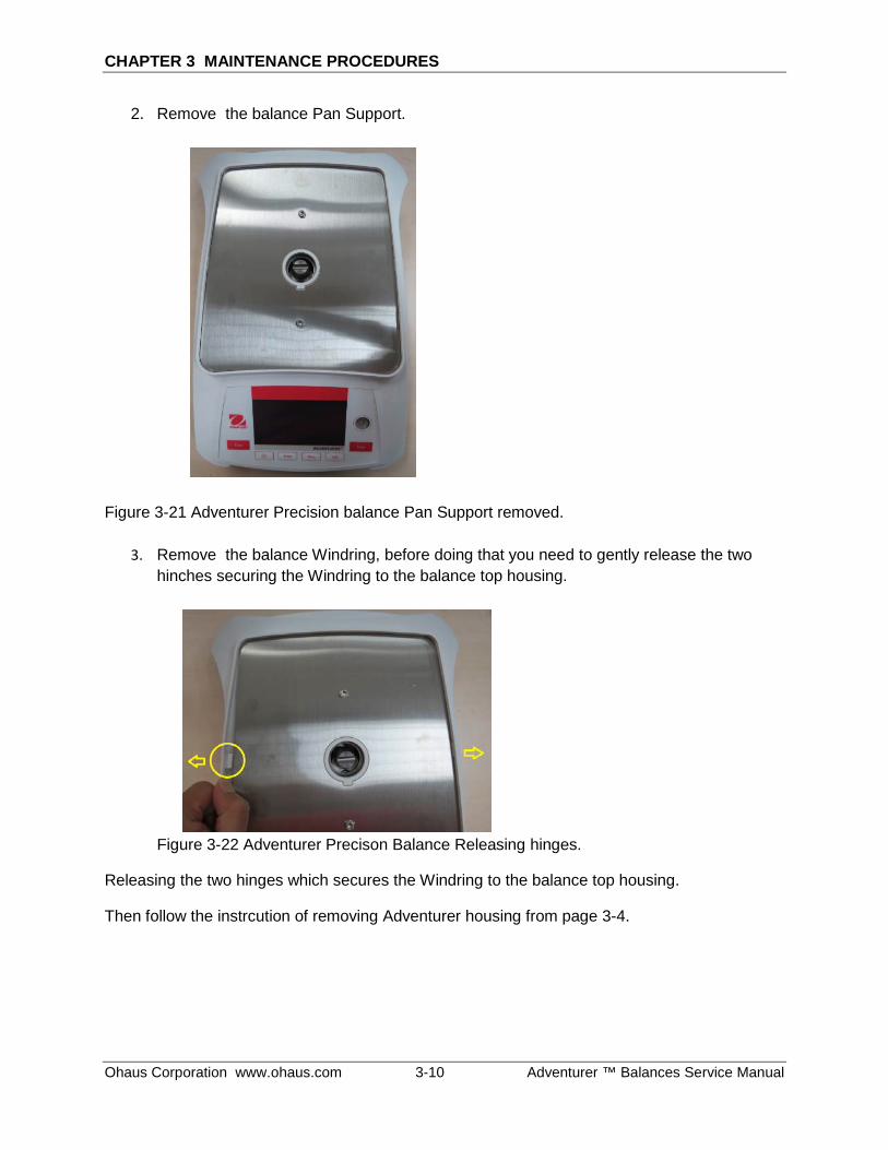
2. Remove the balance Pan Support.
Figure 3-21 Adventurer Precision balance Pan Support removed.
3. Remove the balance Windring, before doing that you need to gently release the two hinches securing the Windring to the balance top housing.
Figure 3-22 Adventurer Precison Balance Releasing hinges.
Releasing the two hinges which secures the Windring to the balance top housing.
Then follow the instrcution of removing Adventurer housing from page 3-4.
CHAPTER 3 MAINTENANCE PROCEDURES
Adventurer ™ Balance Service Manual 3-11 Ohaus Corporation www.ohaus.com
3.3 REPLACING ADVENTURER LOAD CELL
3.3.1 Replacing Adventurer Type conventional MFR load cell.
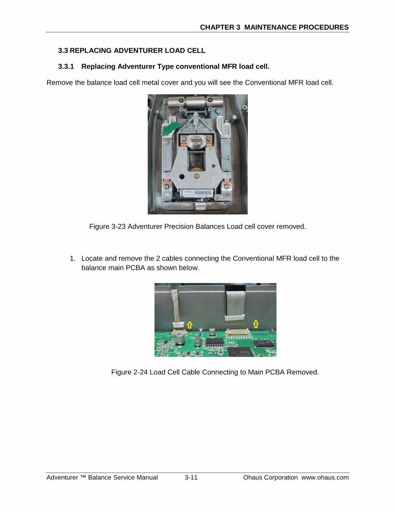
Remove the balance load cell metal cover and you will see the Conventional MFR load cell.
Figure 3-23 Adventurer Precision Balances Load cell cover removed.
1. Locate and remove the 2 cables connecting the Conventional MFR load cell to the balance main PCBA as shown below.
Figure 2-24 Load Cell Cable Connecting to Main PCBA Removed.
CHAPTER 3 MAINTENANCE PROCEDURES
Ohaus Corporation www.ohaus.com 3-12 Adventurer ™ Balances Service Manual
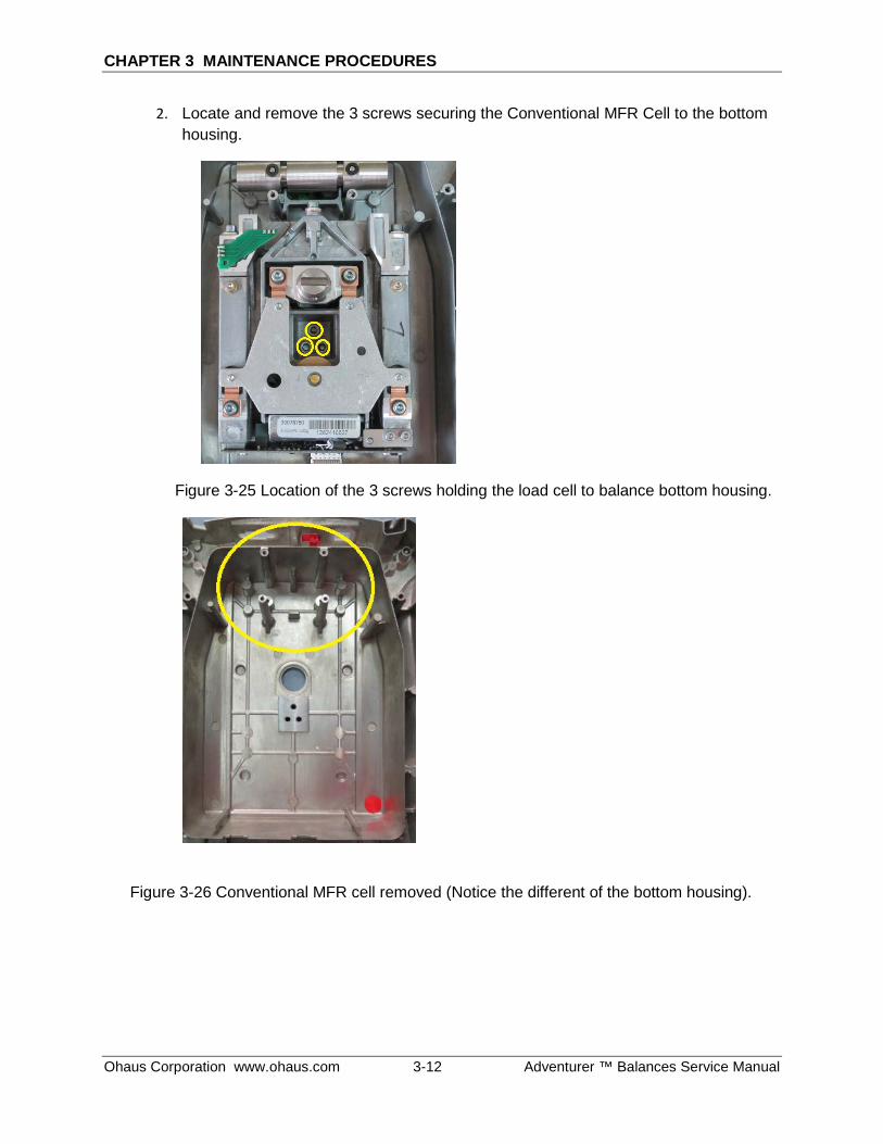
2. Locate and remove the 3 screws securing the Conventional MFR Cell to the bottom housing.
Figure 3-25 Location of the 3 screws holding the load cell to balance bottom housing.
Figure 3-26 Conventional MFR cell removed (Notice the different of the bottom housing).
CHAPTER 3 MAINTENANCE PROCEDURES
Adventurer ™ Balance Service Manual 3-13 Ohaus Corporation www.ohaus.com
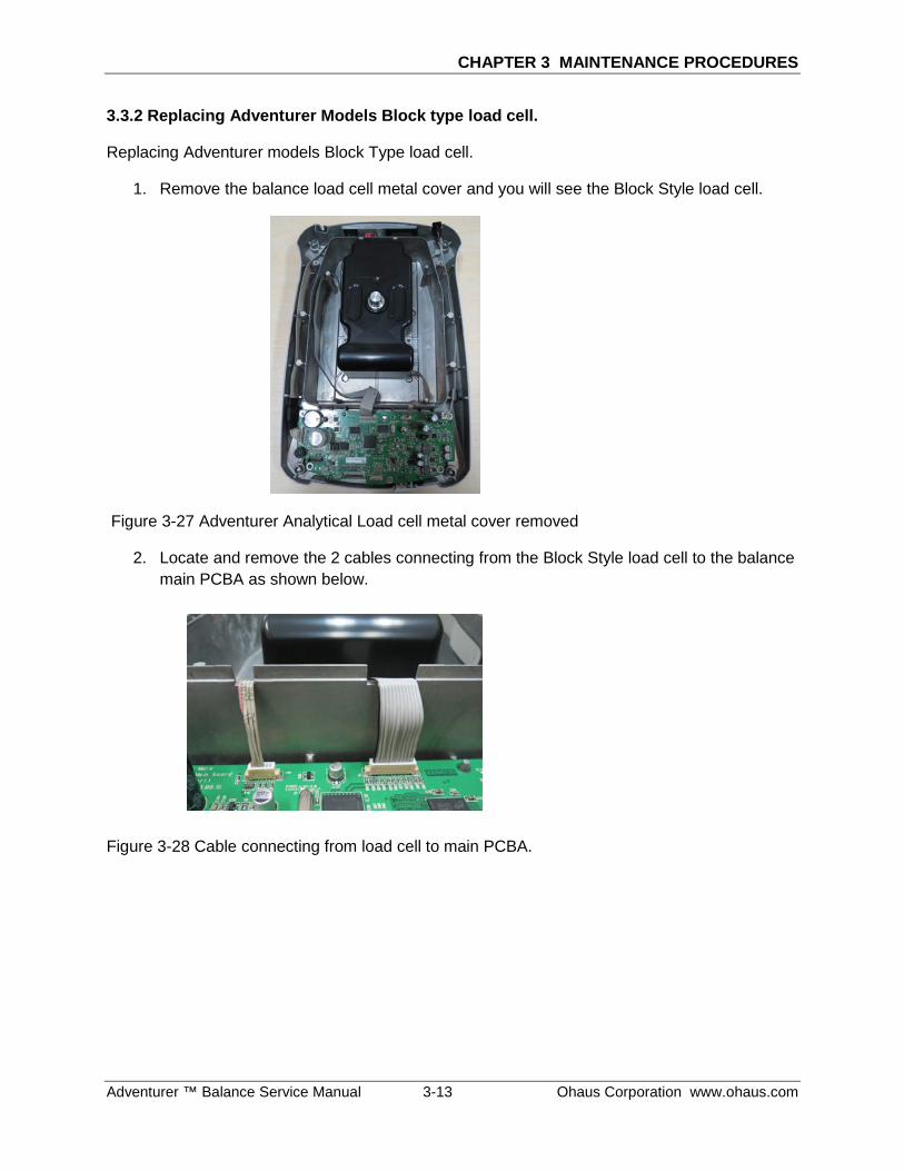
3.3.2 Replacing Adventurer Models Block type load cell.
Replacing Adventurer models Block Type load cell.
1. Remove the balance load cell metal cover and you will see the Block Style load cell.
Figure 3-27 Adventurer Analytical Load cell metal cover removed
2. Locate and remove the 2 cables connecting from the Block Style load cell to the balance main PCBA as shown below.
Figure 3-28 Cable connecting from load cell to main PCBA.
CHAPTER 3 MAINTENANCE PROCEDURES
Ohaus Corporation www.ohaus.com 3-14 Adventurer ™ Balances Service Manual
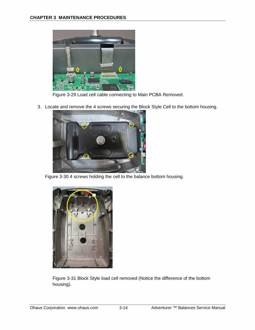
Figure 3-29 Load cell cable connecting to Main PCBA Removed.
3. Locate and remove the 4 screws securing the Block Style Cell to the bottom housing.
Figure 3-30 4 screws holding the cell to the balance bottom housing.
Figure 3-31 Block Style load cell removed (Notice the difference of the bottom housing).
CHAPTER 3 MAINTENANCE PROCEDURES
Adventurer ™ Balance Service Manual 3-15 Ohaus Corporation www.ohaus.com
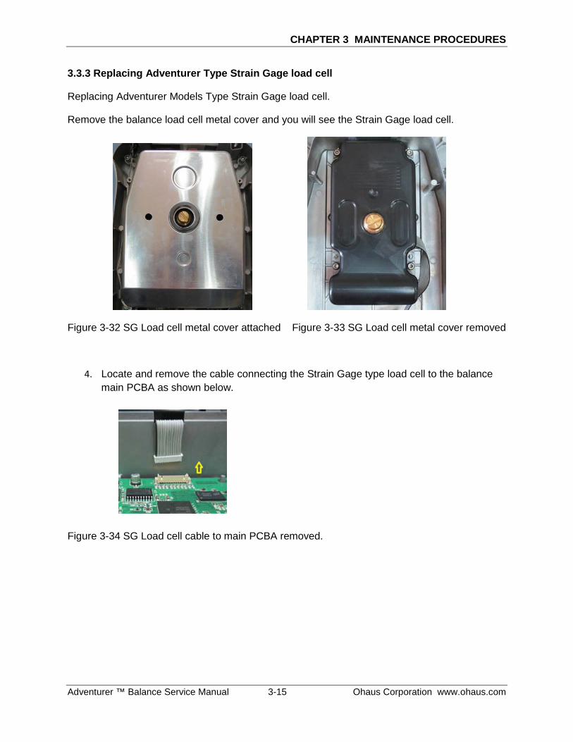
3.3.3 Replacing Adventurer Type Strain Gage load cell
Replacing Adventurer Models Type Strain Gage load cell.
Remove the balance load cell metal cover and you will see the Strain Gage load cell.
Figure 3-32 SG Load cell metal cover attached Figure 3-33 SG Load cell metal cover removed
4. Locate and remove the cable connecting the Strain Gage type load cell to the balance main PCBA as shown below.
Figure 3-34 SG Load cell cable to main PCBA removed.
CHAPTER 3 MAINTENANCE PROCEDURES
Ohaus Corporation www.ohaus.com 3-16 Adventurer ™ Balances Service Manual
5. Locate and remove the 4 screws securing the Strain gage Load Cell to the bottom housing.
Figure 3-35 Location of the 4 screws securing Strain Gage load cell to the balance bottom housing.
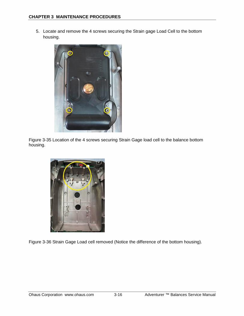
Figure 3-36 Strain Gage Load cell removed (Notice the difference of the bottom housing).
CHAPTER 3 MAINTENANCE PROCEDURES
Adventurer ™ Balance Service Manual 3-17 Ohaus Corporation www.ohaus.com
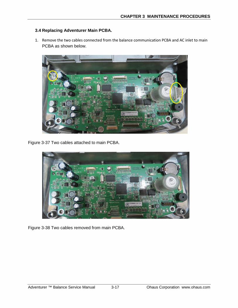
3.4 Replacing Adventurer Main PCBA.
1. Remove the two cables connected from the balance communication PCBA and AC inlet to main PCBA as shown below.
Figure 3-37 Two cables attached to main PCBA.
Figure 3-38 Two cables removed from main PCBA.
CHAPTER 3 MAINTENANCE PROCEDURES
Ohaus Corporation www.ohaus.com 3-18 Adventurer ™ Balances Service Manual
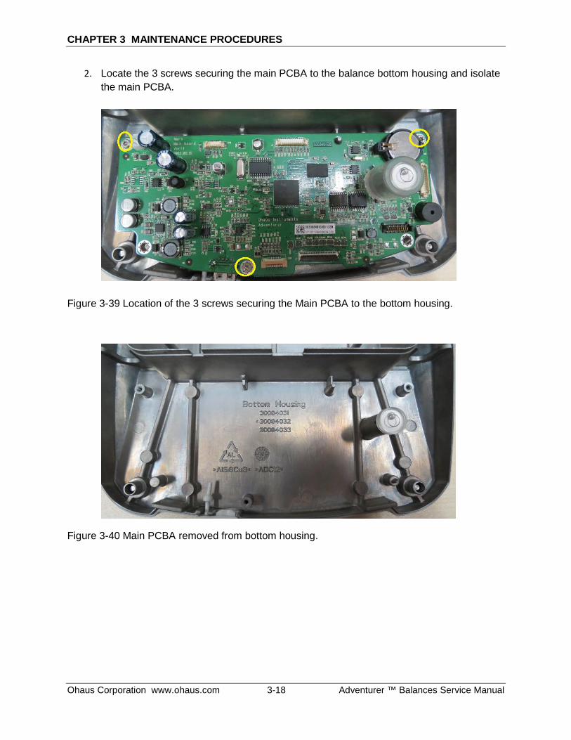
2. Locate the 3 screws securing the main PCBA to the balance bottom housing and isolate the main PCBA.
Figure 3-39 Location of the 3 screws securing the Main PCBA to the bottom housing.
Figure 3-40 Main PCBA removed from bottom housing.
CHAPTER 3 MAINTENANCE PROCEDURES
Adventurer ™ Balance Service Manual 3-19 Ohaus Corporation www.ohaus.com
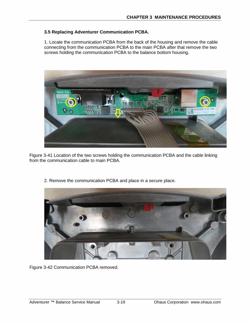
3.5 Replacing Adventurer Communication PCBA.
1. Locate the communication PCBA from the back of the housing and remove the cable connecting from the communication PCBA to the main PCBA after that remove the two screws holding the communication PCBA to the balance bottom housing.
Figure 3-41 Location of the two screws holding the communication PCBA and the cable linking from the communication cable to main PCBA.
2. Remove the communication PCBA and place in a secure place.
Figure 3-42 Communication PCBA removed.
CHAPTER 3 MAINTENANCE PROCEDURES
Ohaus Corporation www.ohaus.com 3-20 Adventurer™ Balances Service Manual
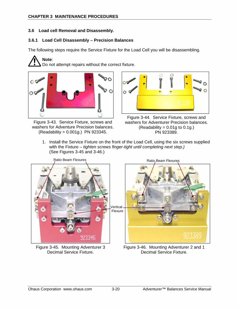
3.6 Load cell Removal and Disassembly.
3.6.1 Load Cell Disassembly – Precision Balances
The following steps require the Service Fixture for the Load Cell you will be disassembling.
Note: Do not attempt repairs without the correct fixture.
Figure 3-43. Service Fixture, screws and
washers for Adventure Precision balances. (Readability = 0.001g.) PN 923345.
Figure 3-44. Service Fixture, screws and
washers for Adventurer Precision balances. (Readability = 0.01g to 0.1g.)
PN 923389.
1. Install the Service Fixture on the front of the Load Cell, using the six screws supplied with the Fixture – tighten screws finger-tight until completing next step.) (See Figures 3-45 and 3-46.)
Figure 3-45. Mounting Adventurer 3
Decimal Service Fixture.
Figure 3-46. Mounting Adventurer 2 and 1
Decimal Service Fixture.
Ratio Beam Flexures
Vertical Flexure
Ratio Beam Flexures
CHAPTER 3 MAINTENANCE PROCEDURES
Adventurer™ Balance Service Manual 3-21 Ohaus Corporation www.ohaus.com
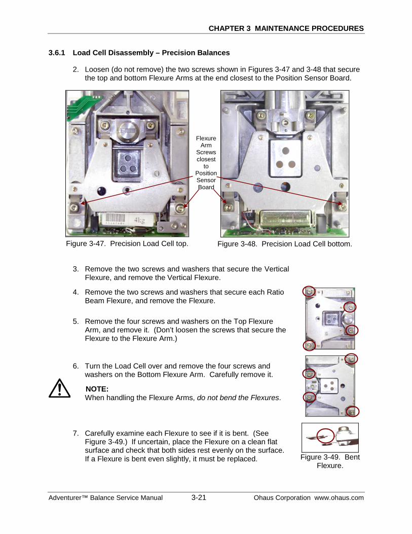
3.6.1 Load Cell Disassembly – Precision Balances
2. Loosen (do not remove) the two screws shown in Figures 3-47 and 3-48 that secure the top and bottom Flexure Arms at the end closest to the Position Sensor Board.
Figure 3-47. Precision Load Cell top.
Figure 3-48. Precision Load Cell bottom.
3. Remove the two screws and washers that secure the Vertical
Flexure, and remove the Vertical Flexure.
4. Remove the two screws and washers that secure each Ratio Beam Flexure, and remove the Flexure.
5. Remove the four screws and washers on the Top Flexure Arm, and remove it. (Don’t loosen the screws that secure the Flexure to the Flexure Arm.)
6. Turn the Load Cell over and remove the four screws and washers on the Bottom Flexure Arm. Carefully remove it.
NOTE: When handling the Flexure Arms, do not bend the Flexures.
7. Carefully examine each Flexure to see if it is bent. (See Figure 3-49.) If uncertain, place the Flexure on a clean flat surface and check that both sides rest evenly on the surface. If a Flexure is bent even slightly, it must be replaced.
Figure 3-49. Bent
Flexure.
Flexure Arm
Screws closest
to Position Sensor Board
CHAPTER 3 MAINTENANCE PROCEDURES
Ohaus Corporation www.ohaus.com 3-22 Adventurer™ Balances Service Manual
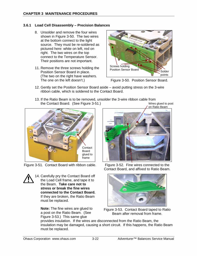
3.6.1 Load Cell Disassembly – Precision Balances
8. Unsolder and remove the four wires shown in Figure 3-50. The two wires at the bottom connect to the light source. They must be re-soldered as pictured here: white on left, red on right. The two wires on the top connect to the Temperature Sensor. Their positions are not important.
11. Remove the three screws holding the Position Sensor Board in place. (The two on the right have washers. The one on the left doesn’t.)
Figure 3-50. Position Sensor Board.
12. Gently set the Position Sensor Board aside – avoid putting stress on the 3-wire ribbon cable, which is soldered to the Contact Board.
13. If the Ratio Beam is to be removed, unsolder the 3-wire ribbon cable from the Contact Board. (See Figure 3-51.)
Figure 3-51. Contact Board with ribbon cable.
Figure 3-52. Fine wires connected to the
Contact Board, and affixed to Ratio Beam.
14. Carefully pry the Contact Board off the Load Cell frame, and tape it to the Beam. Take care not to stress or break the fine wires connected to the Contact Board. If they are broken, the Ratio Beam must be replaced.
Note: The fine wires are glued to a post on the Ratio Beam. (See Figure 3-53.) This same glue
Figure 3-53. Contact Board taped to Ratio
Beam after removal from frame.
provides insulation. If the wires are disconnected from the Ratio Beam, the insulation may be damaged, causing a short circuit. If this happens, the Ratio Beam must be replaced.
Screws holding Position Sensor Board
Contact Board glued to frame
Solder points
Wires glued to post on Ratio Beam
CHAPTER 3 MAINTENANCE PROCEDURES
Adventurer™ Balance Service Manual 3-23 Ohaus Corporation www.ohaus.com
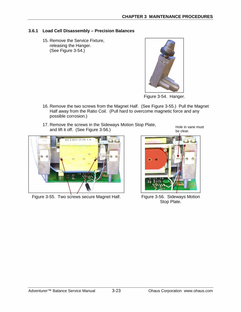
3.6.1 Load Cell Disassembly – Precision Balances
15. Remove the Service Fixture, releasing the Hanger. (See Figure 3-54.)
Figure 3-54. Hanger.
16. Remove the two screws from the Magnet Half. (See Figure 3-55.) Pull the Magnet Half away from the Ratio Coil. (Pull hard to overcome magnetic force and any possible corrosion.)
17. Remove the screws in the Sideways Motion Stop Plate, and lift it off. (See Figure 3-56.)
Figure 3-55. Two screws secure Magnet Half.
Figure 3-56. Sideways Motion
Stop Plate.
Hole in vane must be clear.
CHAPTER 3 MAINTENANCE PROCEDURES
Ohaus Corporation www.ohaus.com 3-24 Adventurer™ Balances Service Manual
3.6.1 Load Cell Disassembly – Precision Balances
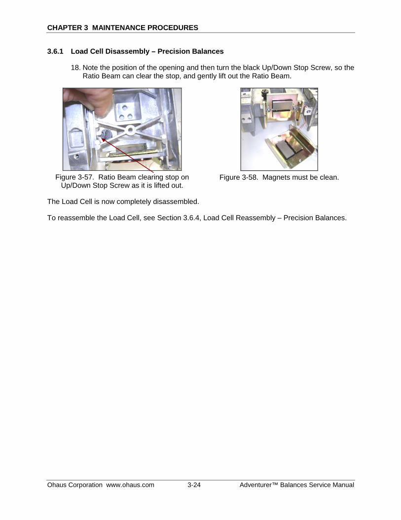
18. Note the position of the opening and then turn the black Up/Down Stop Screw, so the Ratio Beam can clear the stop, and gently lift out the Ratio Beam.
Figure 3-57. Ratio Beam clearing stop on
Up/Down Stop Screw as it is lifted out.
Figure 3-58. Magnets must be clean.
The Load Cell is now completely disassembled.
To reassemble the Load Cell, see Section 3.6.4, Load Cell Reassembly – Precision Balances.
CHAPTER 3 MAINTENANCE PROCEDURES
Adventurer™ Balance Service Manual 3-25 Ohaus Corporation www.ohaus.com
3.6.2 Position Sensor Board Removal/Replacement/Adjustment – Precision
If the Position Sensor Board is defective and requires replacement, proceed as follows:
1. Open the balance, and remove the Load Cell.
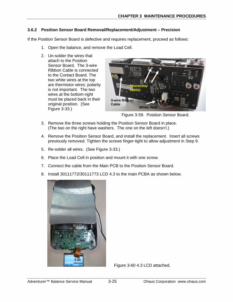
2. Un-solder the wires that attach to the Position Sensor Board. The 3-wire Ribbon Cable is connected to the Contact Board. The two white wires at the top are thermistor wires: polarity is not important. The two wires at the bottom-right must be placed back in their original position. (See Figure 3-33.)
Figure 3-59. Position Sensor Board.
3. Remove the three screws holding the Position Sensor Board in place. (The two on the right have washers. The one on the left doesn’t.)
4. Remove the Position Sensor Board, and install the replacement. Insert all screws previously removed. Tighten the screws finger-tight to allow adjustment in Step 9.
5. Re-solder all wires. (See Figure 3-33.)
6. Place the Load Cell in position and mount it with one screw.
7. Connect the cable from the Main PCB to the Position Sensor Board.
8. Install 30111772/30111773 LCD 4.3 to the main PCBA as shown below.
Figure 3-60 4.3 LCD attached.
3-wire Ribbon Cable
White, Red
Thermistor cables
CHAPTER 3 MAINTENANCE PROCEDURES
Ohaus Corporation www.ohaus.com 3-26 Adventurer™ Balances Service Manual
9. Operate the balance with the Weighing Pan in its normal position, but with the top cover off. Power on using the middle button on the PCB.
NOTE: The Position Sensor Board contains an Optical Sensor which must be positioned in the Ratio Beam’s center of travel for the balance to function properly.
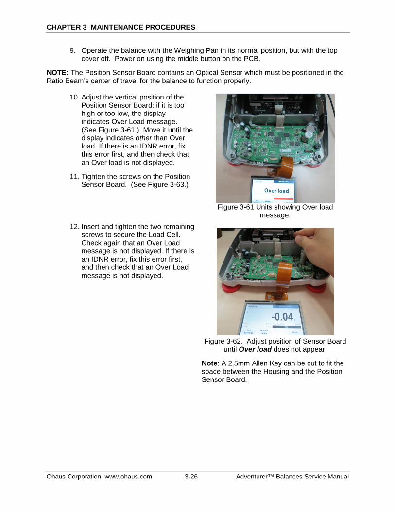
10. Adjust the vertical position of the Position Sensor Board: if it is too high or too low, the display indicates Over Load message. (See Figure 3-61.) Move it until the display indicates other than Over load. If there is an IDNR error, fix this error first, and then check that an Over load is not displayed.
11. Tighten the screws on the Position Sensor Board. (See Figure 3-63.)
12. Insert and tighten the two remaining screws to secure the Load Cell. Check again that an Over Load message is not displayed. If there is an IDNR error, fix this error first, and then check that an Over Load message is not displayed.
Figure 3-61 Units showing Over load
message.
Figure 3-62. Adjust position of Sensor Board
until Over load does not appear.
Note: A 2.5mm Allen Key can be cut to fit the space between the Housing and the Position Sensor Board.
CHAPTER 3 MAINTENANCE PROCEDURES
Adventurer™ Balance Service Manual 3-27 Ohaus Corporation www.ohaus.com
3.6.2 Position Sensor PC Board Removal/Replacement/Adjustment – Precision
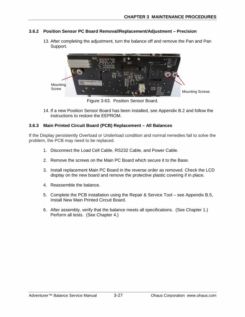
13. After completing the adjustment, turn the balance off and remove the Pan and Pan Support.
Figure 3-63. Position Sensor Board.
14. If a new Position Sensor Board has been installed, see Appendix B.2 and follow the instructions to restore the EEPROM.
3.6.3 Main Printed Circuit Board (PCB) Replacement – All Balances
If the Display persistently Overload or Underload condition and normal remedies fail to solve the problem, the PCB may need to be replaced.
1. Disconnect the Load Cell Cable, RS232 Cable, and Power Cable.
2. Remove the screws on the Main PC Board which secure it to the Base.
3. Install replacement Main PC Board in the reverse order as removed. Check the LCD display on the new board and remove the protective plastic covering if in place.
4. Reassemble the balance.
5. Complete the PCB installation using the Repair & Service Tool – see Appendix B.5, Install New Main Printed Circuit Board.
6. After assembly, verify that the balance meets all specifications. (See Chapter 1.) Perform all tests. (See Chapter 4.)
Mounting Screws
Mounting Screw
CHAPTER 3 MAINTENANCE PROCEDURES
Ohaus Corporation www.ohaus.com 3-28 Adventurer™ Balances Service Manual
3.6.4 Load Cell Reassembly – Precision Balances
Before re-assembly, take the following maintenance steps:
– Be sure all Flexures are straight, or replace them with new ones. Place each Flexure on a clean flat surface and check that both sides rest evenly on the surface. If a Flexure is bent even slightly, it must be replaced. (See Figure 3-23.)
– Be sure all parts are clean and free of debris.
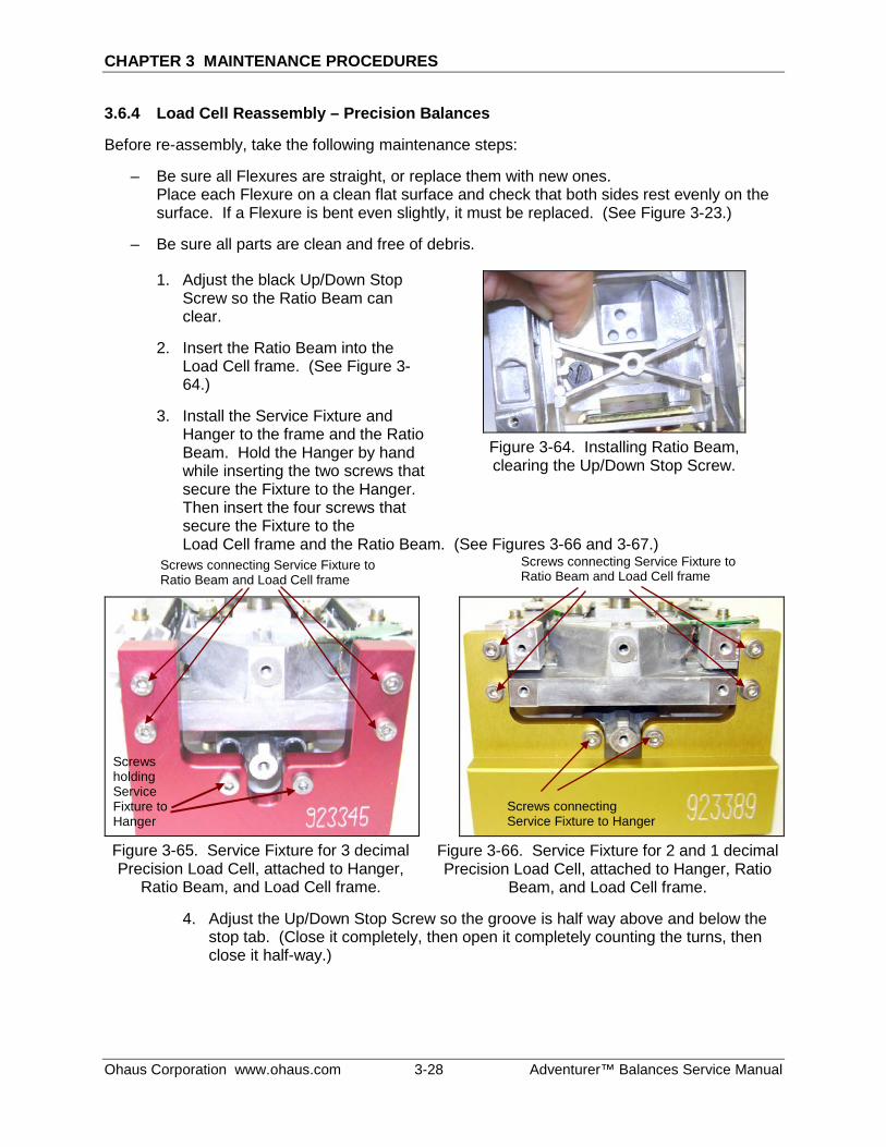
1. Adjust the black Up/Down Stop Screw so the Ratio Beam can clear.
2. Insert the Ratio Beam into the Load Cell frame. (See Figure 3-64.)
3. Install the Service Fixture and Hanger to the frame and the Ratio Beam. Hold the Hanger by hand while inserting the two screws that secure the Fixture to the Hanger. Then insert the four screws that secure the Fixture to the
Figure 3-64. Installing Ratio Beam, clearing the Up/Down Stop Screw.
Load Cell frame and the Ratio Beam. (See Figures 3-66 and 3-67.)
Figure 3-65. Service Fixture for 3 decimal Precision Load Cell, attached to Hanger,
Ratio Beam, and Load Cell frame.
Figure 3-66. Service Fixture for 2 and 1 decimal Precision Load Cell, attached to Hanger, Ratio
Beam, and Load Cell frame.
4. Adjust the Up/Down Stop Screw so the groove is half way above and below the stop tab. (Close it completely, then open it completely counting the turns, then close it half-way.)
Screws holding Service Fixture to Hanger
Screws connecting Service Fixture to Hanger
Screws connecting Service Fixture to Ratio Beam and Load Cell frame
Screws connecting Service Fixture to Ratio Beam and Load Cell frame
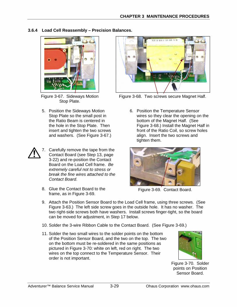
CHAPTER 3 MAINTENANCE PROCEDURES
Adventurer™ Balance Service Manual 3-29 Ohaus Corporation www.ohaus.com
3.6.4 Load Cell Reassembly – Precision Balances.
Figure 3-67. Sideways Motion
Stop Plate.
Figure 3-68. Two screws secure Magnet Half.
5. Position the Sideways Motion Stop Plate so the small post in the Ratio Beam is centered in the hole in the Stop Plate. Then insert and tighten the two screws and washers. (See Figure 3-67.)
6. Position the Temperature Sensor wires so they clear the opening on the bottom of the Magnet Half. (See Figure 3-68.) Install the Magnet Half in front of the Ratio Coil, so screw holes align. Insert the two screws and tighten them.
7. Carefully remove the tape from the Contact Board (see Step 13, page 3-22) and re-position the Contact Board on the Load Cell frame. Be extremely careful not to stress or break the fine wires attached to the Contact Board.
8. Glue the Contact Board to the frame, as in Figure 3-69.
Figure 3-69. Contact Board.
9. Attach the Position Sensor Board to the Load Cell frame, using three screws. (See Figure 3-63.) The left side screw goes in the outside hole. It has no washer. The two right-side screws both have washers. Install screws finger-tight, so the board can be moved for adjustment, in Step 17 below.
10. Solder the 3-wire Ribbon Cable to the Contact Board. (See Figure 3-69.)
11. Solder the two small wires to the solder points on the bottom of the Position Sensor Board, and the two on the top. The two on the bottom must be re-soldered in the same positions as pictured in Figure 3-70: white on left, red on right. The two wires on the top connect to the Temperature Sensor. Their order is not important.
Figure 3-70. Solder points on Position
Sensor Board.
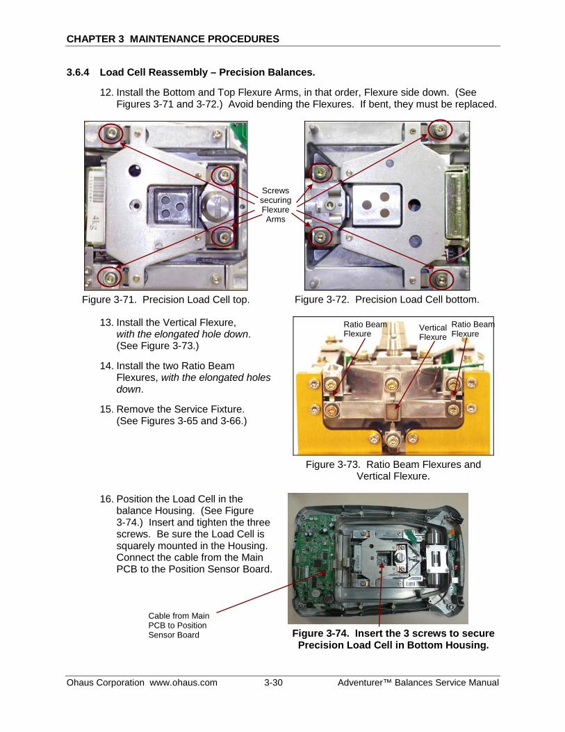
CHAPTER 3 MAINTENANCE PROCEDURES
Ohaus Corporation www.ohaus.com 3-30 Adventurer™ Balances Service Manual
3.6.4 Load Cell Reassembly – Precision Balances.
12. Install the Bottom and Top Flexure Arms, in that order, Flexure side down. (See Figures 3-71 and 3-72.) Avoid bending the Flexures. If bent, they must be replaced.
Figure 3-71. Precision Load Cell top.
Figure 3-72. Precision Load Cell bottom.
13. Install the Vertical Flexure, with the elongated hole down. (See Figure 3-73.)
14. Install the two Ratio Beam Flexures, with the elongated holes down.
15. Remove the Service Fixture. (See Figures 3-65 and 3-66.)
Figure 3-73. Ratio Beam Flexures and Vertical Flexure.
16. Position the Load Cell in the balance Housing. (See Figure 3-74.) Insert and tighten the three screws. Be sure the Load Cell is squarely mounted in the Housing. Connect the cable from the Main PCB to the Position Sensor Board.
Figure 3-74. Insert the 3 screws to secure
Precision Load Cell in Bottom Housing.
Screws securing Flexure Arms
Cable from Main PCB to Position Sensor Board
Ratio Beam Flexure
Vertical Flexure
Ratio Beam Flexure
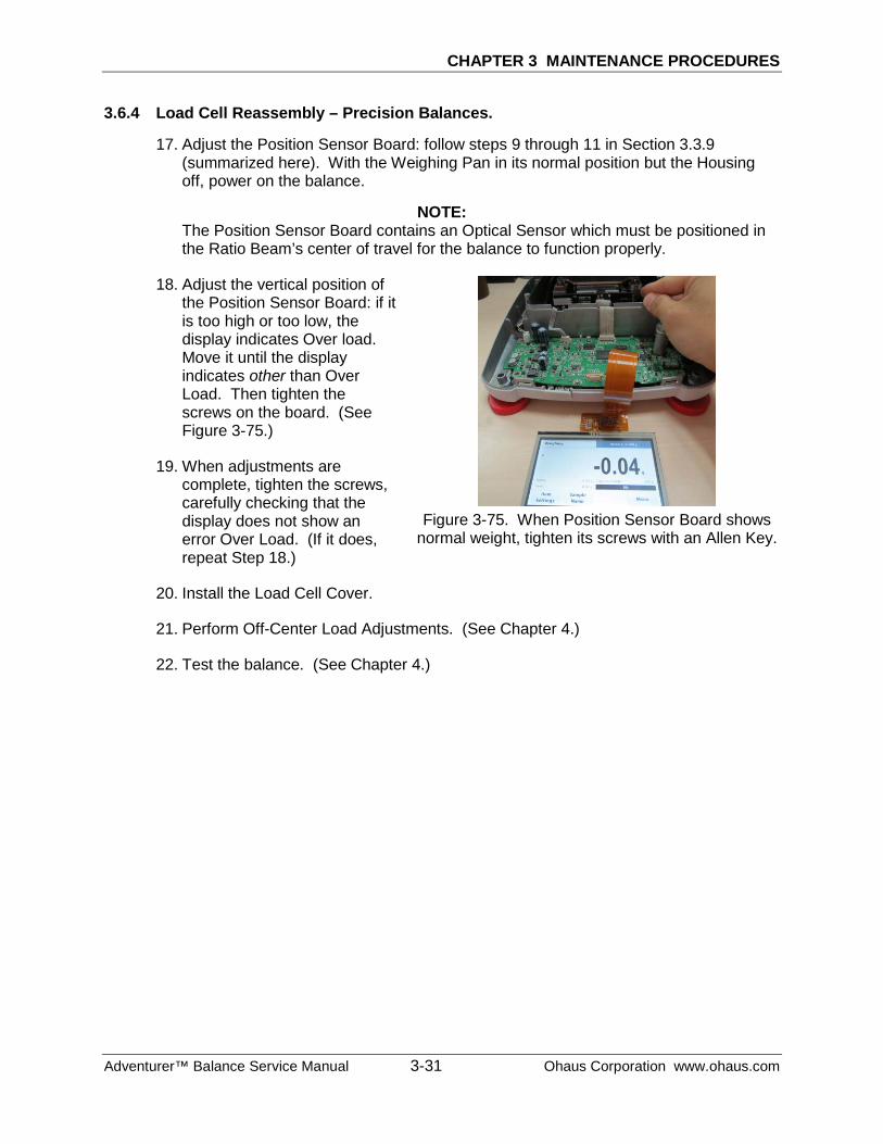
CHAPTER 3 MAINTENANCE PROCEDURES
Adventurer™ Balance Service Manual 3-31 Ohaus Corporation www.ohaus.com
3.6.4 Load Cell Reassembly – Precision Balances.
17. Adjust the Position Sensor Board: follow steps 9 through 11 in Section 3.3.9 (summarized here). With the Weighing Pan in its normal position but the Housing off, power on the balance.
NOTE: The Position Sensor Board contains an Optical Sensor which must be positioned in the Ratio Beam’s center of travel for the balance to function properly.
18. Adjust the vertical position of the Position Sensor Board: if it is too high or too low, the display indicates Over load. Move it until the display indicates other than Over Load. Then tighten the screws on the board. (See Figure 3-75.)
19. When adjustments are complete, tighten the screws, carefully checking that the display does not show an error Over Load. (If it does, repeat Step 18.)
Figure 3-75. When Position Sensor Board shows
normal weight, tighten its screws with an Allen Key.
20. Install the Load Cell Cover.
21. Perform Off-Center Load Adjustments. (See Chapter 4.)
22. Test the balance. (See Chapter 4.)
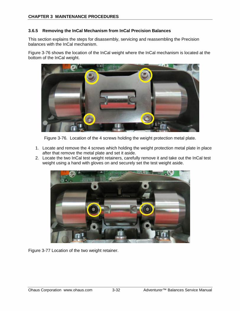
CHAPTER 3 MAINTENANCE PROCEDURES
Ohaus Corporation www.ohaus.com 3-32 Adventurer™ Balances Service Manual
3.6.5 Removing the InCal Mechanism from InCal Precision Balances
This section explains the steps for disassembly, servicing and reassembling the Precision balances with the InCal mechanism.
Figure 3-76 shows the location of the InCal weight where the InCal mechanism is located at the bottom of the InCal weight.
Figure 3-76. Location of the 4 screws holding the weight protection metal plate.
1. Locate and remove the 4 screws which holding the weight protection metal plate in place after that remove the metal plate and set it aside.
2. Locate the two InCal test weight retainers, carefully remove it and take out the InCal test weight using a hand with gloves on and securely set the test weight aside.
Figure 3-77 Location of the two weight retainer.
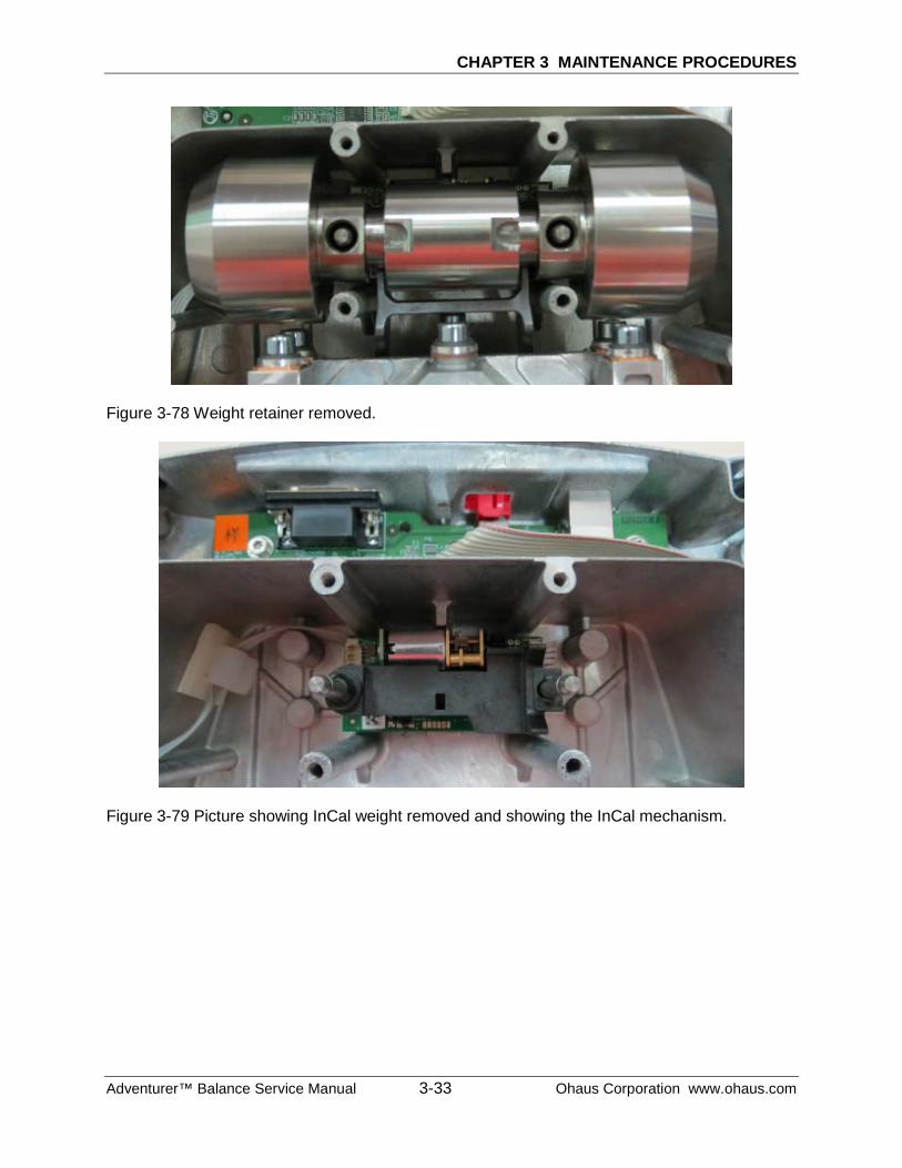
CHAPTER 3 MAINTENANCE PROCEDURES
Adventurer™ Balance Service Manual 3-33 Ohaus Corporation www.ohaus.com
Figure 3-78 Weight retainer removed.
Figure 3-79 Picture showing InCal weight removed and showing the InCal mechanism.
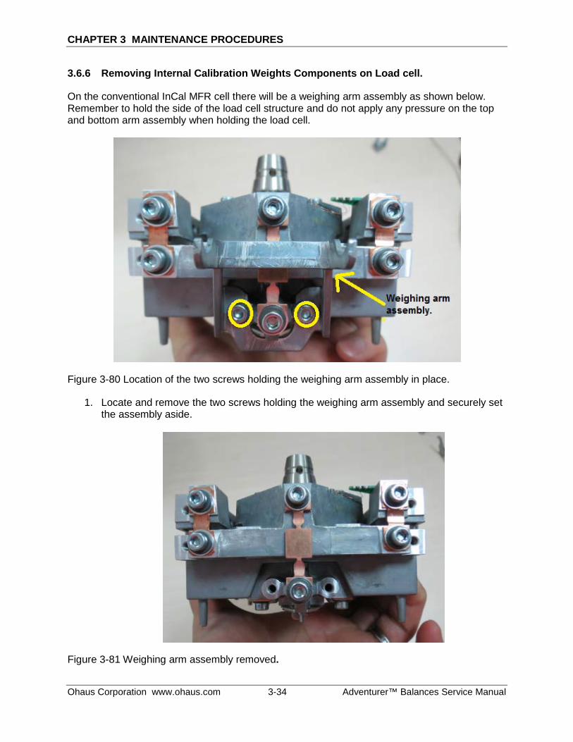
CHAPTER 3 MAINTENANCE PROCEDURES
Ohaus Corporation www.ohaus.com 3-34 Adventurer™ Balances Service Manual
3.6.6 Removing Internal Calibration Weights Components on Load cell.
On the conventional InCal MFR cell there will be a weighing arm assembly as shown below. Remember to hold the side of the load cell structure and do not apply any pressure on the top and bottom arm assembly when holding the load cell.
Figure 3-80 Location of the two screws holding the weighing arm assembly in place.
1. Locate and remove the two screws holding the weighing arm assembly and securely set the assembly aside.
Figure 3-81 Weighing arm assembly removed.
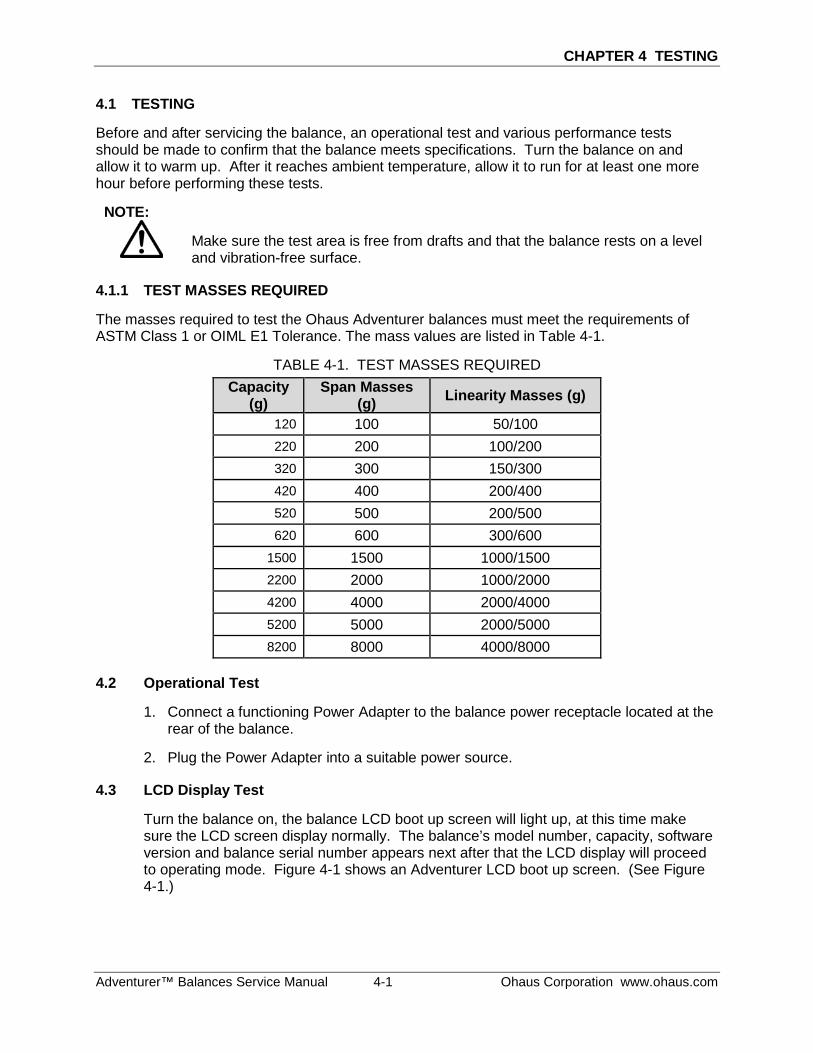
CHAPTER 4 TESTING
Adventurer™ Balances Service Manual 4-1 Ohaus Corporation www.ohaus.com
4.1 TESTING
Before and after servicing the balance, an operational test and various performance tests should be made to confirm that the balance meets specifications. Turn the balance on and allow it to warm up. After it reaches ambient temperature, allow it to run for at least one more hour before performing these tests.
NOTE:
Make sure the test area is free from drafts and that the balance rests on a level and vibration-free surface.
4.1.1 TEST MASSES REQUIRED
The masses required to test the Ohaus Adventurer balances must meet the requirements of ASTM Class 1 or OIML E1 Tolerance. The mass values are listed in Table 4-1.
TABLE 4-1. TEST MASSES REQUIRED Capacity
(g) Span Masses
(g) Linearity Masses (g)
120 100 50/100 220 200 100/200 320 300 150/300 420 400 200/400 520 500 200/500 620 600 300/600
1500 1500 1000/1500 2200 2000 1000/2000 4200 4000 2000/4000 5200 5000 2000/5000 8200 8000 4000/8000
4.2 Operational Test
1. Connect a functioning Power Adapter to the balance power receptacle located at the rear of the balance.
2. Plug the Power Adapter into a suitable power source.
4.3 LCD Display Test
Turn the balance on, the balance LCD boot up screen will light up, at this time make sure the LCD screen display normally. The balance’s model number, capacity, software version and balance serial number appears next after that the LCD display will proceed to operating mode. Figure 4-1 shows an Adventurer LCD boot up screen. (See Figure 4-1.)
CHAPTER 4 TESTING
Ohaus Corporation www.ohaus.com 4-2 Adventurer™ Balances Service Manual
Figure 4-1. Adventurer LCD boot up screen.
4.4 Performance Tests – Precision & Analytical Balances
Accurate performance of the Adventure balances is determined by a series of four performance tests. The displayed readings are compared with the tolerances listed in Tables 4-2 and 4-3. Tolerance values are expressed in counts. A one-count difference is shown in the last digit on the balance display.
TABEL 4-2. TOLERANCES-PRECISION MODELS
Performance Test TOLERANCE – COUNTS
AX223 AX423 AX523 AX622 AX1502 AX2202 AX4202 AX5202 AX4201 AX8201
Precision (counts) ±1 ±1 ±1 ±1 ±1 ±1 ±1 ±1 ±1 ±1
Off Center Load (mg) ±4 ±4 ±4 ±40 ±40 ±40 ±40 ±40 ±400 ±400
Repeatability (mg) ±1 ±1 ±1 ±10 ±10 ±10 ±10 ±10 ±100 ±100
Linearity (mg) ±2 ±2 ±2 ±20 ±20 ±20 ±20 ±20 ±200 ±200
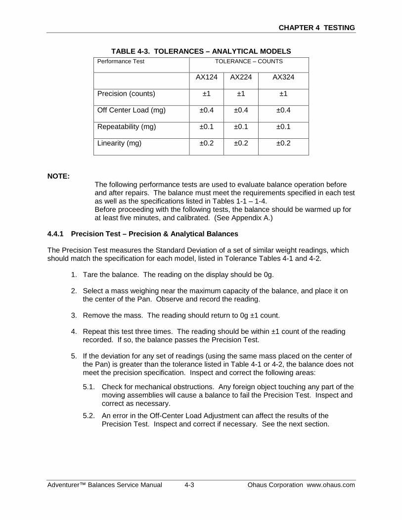
CHAPTER 4 TESTING
Adventurer™ Balances Service Manual 4-3 Ohaus Corporation www.ohaus.com
TABLE 4-3. TOLERANCES – ANALYTICAL MODELS Performance Test TOLERANCE – COUNTS
AX124 AX224 AX324
Precision (counts) ±1 ±1 ±1
Off Center Load (mg) ±0.4 ±0.4 ±0.4
Repeatability (mg) ±0.1 ±0.1 ±0.1
Linearity (mg) ±0.2 ±0.2 ±0.2
NOTE: The following performance tests are used to evaluate balance operation before and after repairs. The balance must meet the requirements specified in each test as well as the specifications listed in Tables 1-1 – 1-4. Before proceeding with the following tests, the balance should be warmed up for at least five minutes, and calibrated. (See Appendix A.)
4.4.1 Precision Test – Precision & Analytical Balances
The Precision Test measures the Standard Deviation of a set of similar weight readings, which should match the specification for each model, listed in Tolerance Tables 4-1 and 4-2.
1. Tare the balance. The reading on the display should be 0g.
2. Select a mass weighing near the maximum capacity of the balance, and place it on the center of the Pan. Observe and record the reading.
3. Remove the mass. The reading should return to 0g ±1 count.
4. Repeat this test three times. The reading should be within ±1 count of the reading recorded. If so, the balance passes the Precision Test.
5. If the deviation for any set of readings (using the same mass placed on the center of the Pan) is greater than the tolerance listed in Table 4-1 or 4-2, the balance does not meet the precision specification. Inspect and correct the following areas:
5.1. Check for mechanical obstructions. Any foreign object touching any part of the moving assemblies will cause a balance to fail the Precision Test. Inspect and correct as necessary.
5.2. An error in the Off-Center Load Adjustment can affect the results of the Precision Test. Inspect and correct if necessary. See the next section.
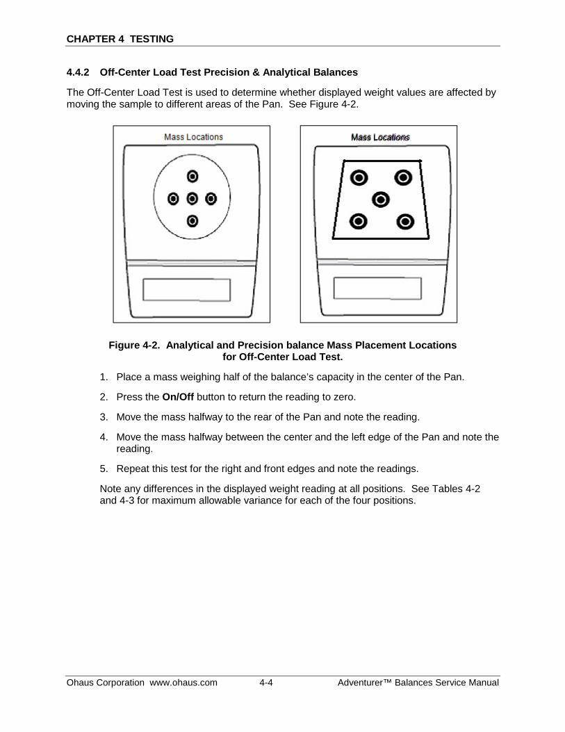
CHAPTER 4 TESTING
Ohaus Corporation www.ohaus.com 4-4 Adventurer™ Balances Service Manual
4.4.2 Off-Center Load Test Precision & Analytical Balances
The Off-Center Load Test is used to determine whether displayed weight values are affected by moving the sample to different areas of the Pan. See Figure 4-2.
Figure 4-2. Analytical and Precision balance Mass Placement Locations for Off-Center Load Test.
1. Place a mass weighing half of the balance’s capacity in the center of the Pan.
2. Press the On/Off button to return the reading to zero.
3. Move the mass halfway to the rear of the Pan and note the reading.
4. Move the mass halfway between the center and the left edge of the Pan and note the reading.
5. Repeat this test for the right and front edges and note the readings.
Note any differences in the displayed weight reading at all positions. See Tables 4-2 and 4-3 for maximum allowable variance for each of the four positions.
Mass Locations
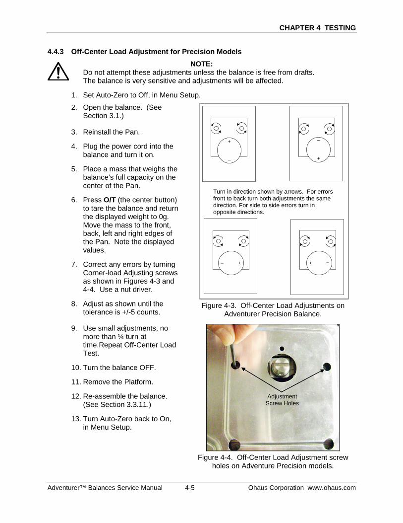
CHAPTER 4 TESTING
Adventurer™ Balances Service Manual 4-5 Ohaus Corporation www.ohaus.com
4.4.3 Off-Center Load Adjustment for Precision Models NOTE:
Do not attempt these adjustments unless the balance is free from drafts. The balance is very sensitive and adjustments will be affected.
1. Set Auto-Zero to Off, in Menu Setup.
2. Open the balance. (See Section 3.1.)
3. Reinstall the Pan.
4. Plug the power cord into the balance and turn it on.
5. Place a mass that weighs the balance’s full capacity on the center of the Pan.
6. Press O/T (the center button) to tare the balance and return the displayed weight to 0g. Move the mass to the front, back, left and right edges of the Pan. Note the displayed values.
7. Correct any errors by turning Corner-load Adjusting screws as shown in Figures 4-3 and 4-4. Use a nut driver.
8. Adjust as shown until the tolerance is +/-5 counts.
+
– +
–
+–
+ –
Figure 4-3. Off-Center Load Adjustments on
Adventurer Precision Balance.
9. Use small adjustments, no more than ¼ turn at time.Repeat Off-Center Load Test.
10. Turn the balance OFF.
11. Remove the Platform.
12. Re-assemble the balance. (See Section 3.3.11.)
13. Turn Auto-Zero back to On, in Menu Setup.
Figure 4-4. Off-Center Load Adjustment screw holes on Adventure Precision models.
Adjustment Screw Holes
Turn in direction shown by arrows. For errors front to back turn both adjustments the same direction. For side to side errors turn in opposite directions.
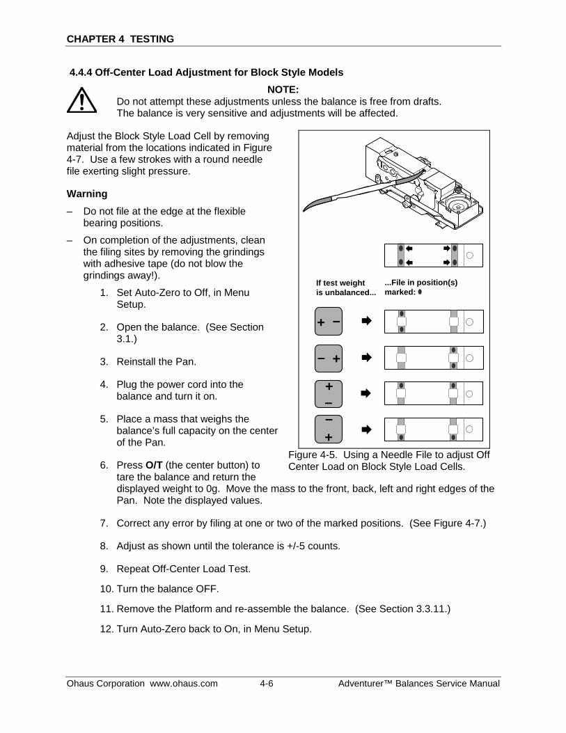
CHAPTER 4 TESTING
Ohaus Corporation www.ohaus.com 4-6 Adventurer™ Balances Service Manual
4.4.4 Off-Center Load Adjustment for Block Style Models NOTE:
Do not attempt these adjustments unless the balance is free from drafts. The balance is very sensitive and adjustments will be affected.
Adjust the Block Style Load Cell by removing material from the locations indicated in Figure 4-7. Use a few strokes with a round needle file exerting slight pressure.
Warning – Do not file at the edge at the flexible
bearing positions.
– On completion of the adjustments, clean the filing sites by removing the grindings with adhesive tape (do not blow the grindings away!).
1. Set Auto-Zero to Off, in Menu Setup.
2. Open the balance. (See Section 3.1.)
3. Reinstall the Pan.
4. Plug the power cord into the balance and turn it on.
5. Place a mass that weighs the balance’s full capacity on the center of the Pan.
6. Press O/T (the center button) to tare the balance and return the
+
+
+
+
Æ
Æ
Æ
Æ
If test weightis unbalanced...
Æ
Æ
Æ
Æ
–
–
–
–
...File in position(s) marked:
Figure 4-5. Using a Needle File to adjust Off Center Load on Block Style Load Cells.
displayed weight to 0g. Move the mass to the front, back, left and right edges of the Pan. Note the displayed values.
7. Correct any error by filing at one or two of the marked positions. (See Figure 4-7.)
8. Adjust as shown until the tolerance is +/-5 counts.
9. Repeat Off-Center Load Test.
10. Turn the balance OFF.
11. Remove the Platform and re-assemble the balance. (See Section 3.3.11.)
12. Turn Auto-Zero back to On, in Menu Setup.
CHAPTER 4 TESTING
Adventurer™ Balances Service Manual 4-7 Ohaus Corporation www.ohaus.com
4.4.5 Repeatability Test
Repeatability is the Standard Deviation of a set of similar weight readings.
Requirements: – To perform this test a single mass must be used for all readings.
– The test mass should be approximately ½ of the capacity of the instrument.
– Wear gloves when handling the mass.
Before starting a repeatability test, set up the instrument as follows:
Set Up: Enter the menu and adjust and record the following settings:
A. Set the Filter level to medium or the center of its range.
B. Set the AZT (Auto Zero Tracking) to .5d or its lowest setting. Do not turn it off.
C. Set the instrument to display the same units as the performance specifications. (Usually kg, g, or mg)
Record Settings: Filter Level Setting = ____________
Auto Zero Tracking Setting = ____________
Displayed Units = ____________
Mass Used = ____________
TEST PROCEDURE: 1. Zero the instrument, if it does not read zero.
2. Using a test mass approximately half the capacity of the instrument, place the mass on the center of platform. Record the reading on the worksheet provided.
3. Remove the mass from the platform.
4. Repeat this test starting at Step 1 until you record a total of ten readings
Fill in the worksheet (Table 4-4) with the ten (10) readings.
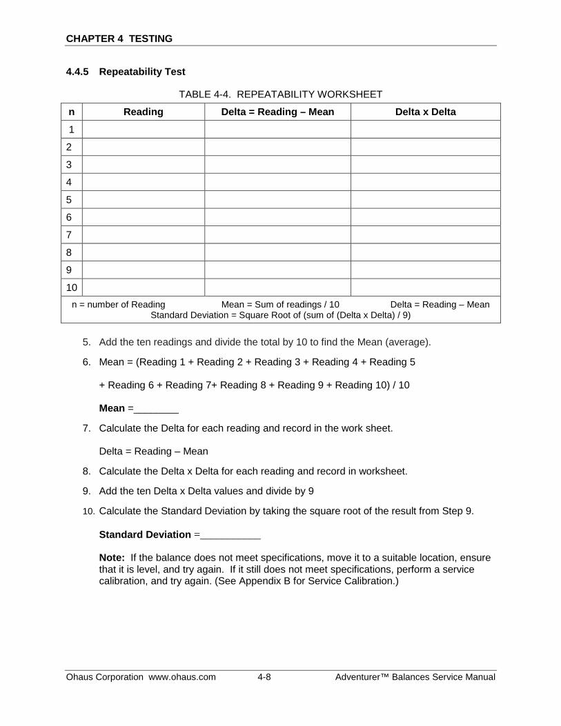
CHAPTER 4 TESTING
Ohaus Corporation www.ohaus.com 4-8 Adventurer™ Balances Service Manual
4.4.5 Repeatability Test
TABLE 4-4. REPEATABILITY WORKSHEET
n Reading Delta = Reading – Mean Delta x Delta
1
2
3
4
5
6
7
8
9
10 n = number of Reading Mean = Sum of readings / 10 Delta = Reading – Mean
Standard Deviation = Square Root of (sum of (Delta x Delta) / 9)
5. Add the ten readings and divide the total by 10 to find the Mean (average).
6. Mean = (Reading 1 + Reading 2 + Reading 3 + Reading 4 + Reading 5 + Reading 6 + Reading 7+ Reading 8 + Reading 9 + Reading 10) / 10 Mean =________
7. Calculate the Delta for each reading and record in the work sheet. Delta = Reading – Mean
8. Calculate the Delta x Delta for each reading and record in worksheet.
9. Add the ten Delta x Delta values and divide by 9
10. Calculate the Standard Deviation by taking the square root of the result from Step 9. Standard Deviation =___________
Note: If the balance does not meet specifications, move it to a suitable location, ensure that it is level, and try again. If it still does not meet specifications, perform a service calibration, and try again. (See Appendix B for Service Calibration.)
CHAPTER 4 TESTING
Adventurer™ Balances Service Manual 4-9 Ohaus Corporation www.ohaus.com
4.4.6 Linearity Test
This test is used to determine the linearity of the unit throughout its operating range. The displayed readings are compared with the tolerances listed in the specifications for the instrument. (See Specifications Tables, Chapter 1.) Tolerance values are expressed in counts. A one-count change is equal to the last digit shown on the scale display. The masses used to perform this test can be utility masses.
NOTE: The balance must be warmed up prior to performing these tests, and must pass the Precision, Off-Center Load Test and Repeatability Tests, and be calibrated before the Linearity Test may be performed.
The Reference Mass should be approximately 1/8 of the full capacity of the balance. USE THE SAME REFERENCE MASS THROUGHOUT THE LINEARITY TEST.
1. Press ZERO to zero the display.
2. Place the Reference Mass in the center of the pan and record the exact value (all decimal places) displayed.
3. Remove the Reference Mass and verify that the display returns to zero. If it does not, disregard the reading, press ZERO to re-zero the display, and repeat the process.
4. Place a mass equal to ¼ of the full scale capacity on the platform and press ZERO.
5. Add the Reference Mass to the center of the platform and record the value.
6. Remove the Reference Mass and verify that the display returns to zero. If it does not, disregard the reading, press ZERO to re-zero the display, and repeat the process.
7. Place a mass equal to ½ of the full-scale capacity on the platform and press ZERO.
8. Add the Reference Mass to the center of the platform and record the value.
9. Remove the Reference Mass and verify that the display returns to zero. If it does not, disregard the reading, press ZERO to re-zero the display, and repeat the process.
10. Place a mass equal to ¾ of the full scale capacity on the platform and press ZERO.
11. Add the Reference Mass to the center of the platform and record the value.
12. Remove the Reference Mass and verify that the display returns to zero. If it does not, disregard the reading, press ZERO to re-zero the display, and repeat the process.
13. Calculate the weight differences between the readings as shown below.
14. The maximum difference should be less than or equal to the Linearity specification for the instrument. (See Specification Tables, Chapter 1.)
CHAPTER 4 TESTING
Ohaus Corporation www.ohaus.com 4-10 Adventurer™ Balances Service Manual
4.4.6 Linearity Test
Record Readings
Reading 1 Reference Weight added to zero ________________
Reading 2 Reference Weight added at ¼ full-scale capacity: ________________
Reading 3 Reference Weight added at ½ full-scale capacity: ________________
Reading 4 Reference Weight added at ¾ full-scale capacity: ________________
Calculate Differences
Reading 1 – [(Reading 1 + Reading 2) / 2] = ________________
Reading 2 – [(Reading 2 + Reading 3) / 2] = ________________
Reading 3 – [(Reading 3 + Reading 4) / 2] = ________________
Maximum Difference _______________
The difference in the weights of the test mass should be within the tolerance in Table 1-2. If not, perform a Standard Calibration – both Span and Linearity (see Appendix A) and repeat the test.
If the balance remains out of tolerance, the Load Cell may need to be repaired.
CHAPTER 5 PARTS LISTS & DIAGRAMS
Adventurer™ Balances Service Manual 5-1 Ohaus Corporation www.ohaus.com
This section contains exploded views of the Adventurer (AX) series balances. The exploded view drawings are designed to identify the parts which can be serviced on the balance in the field.
There are many Adventurer (AX) models that have the same parts.
If further technical information is needed, please contact:
www.ohaus.com Ohaus Corporation 7 Campus Drive Suite 310 Parsippany, NJ 07054 USA Tel: (973) 377-9000 Fax: (973) 944-7177.
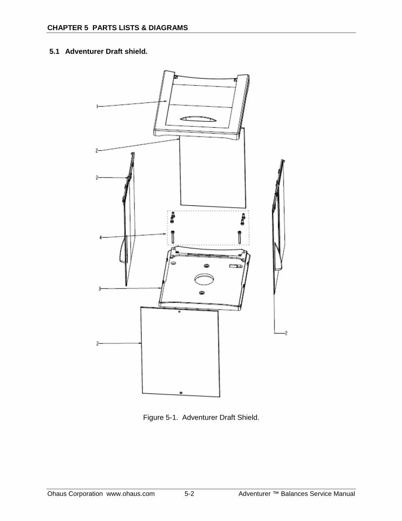
CHAPTER 5 PARTS LISTS & DIAGRAMS
Ohaus Corporation www.ohaus.com 5-2 Adventurer ™ Balances Service Manual
5.1 Adventurer Draft shield.
Figure 5-1. Adventurer Draft Shield.
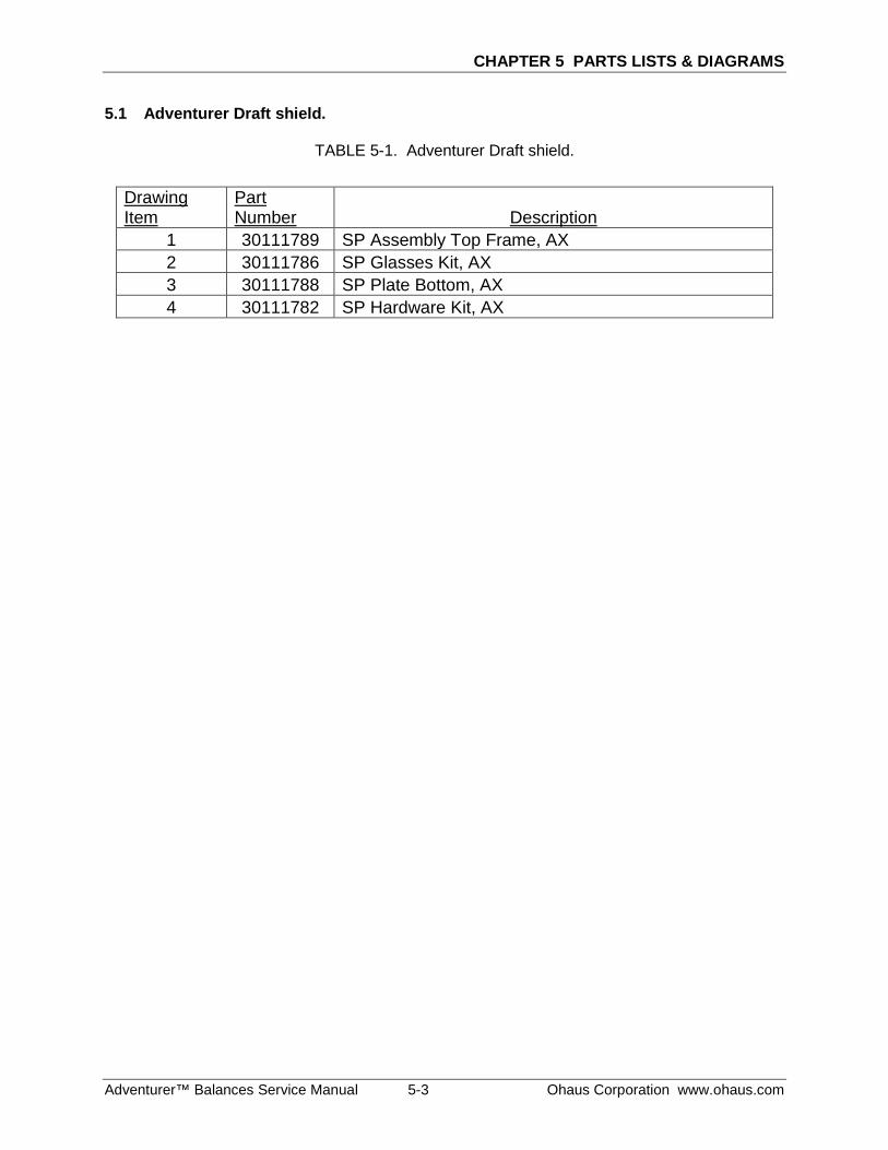
CHAPTER 5 PARTS LISTS & DIAGRAMS
Adventurer™ Balances Service Manual 5-3 Ohaus Corporation www.ohaus.com
5.1 Adventurer Draft shield.
TABLE 5-1. Adventurer Draft shield.
Drawing Item
Part Number Description
1 30111789 SP Assembly Top Frame, AX 2 30111786 SP Glasses Kit, AX 3 30111788 SP Plate Bottom, AX 4 30111782 SP Hardware Kit, AX
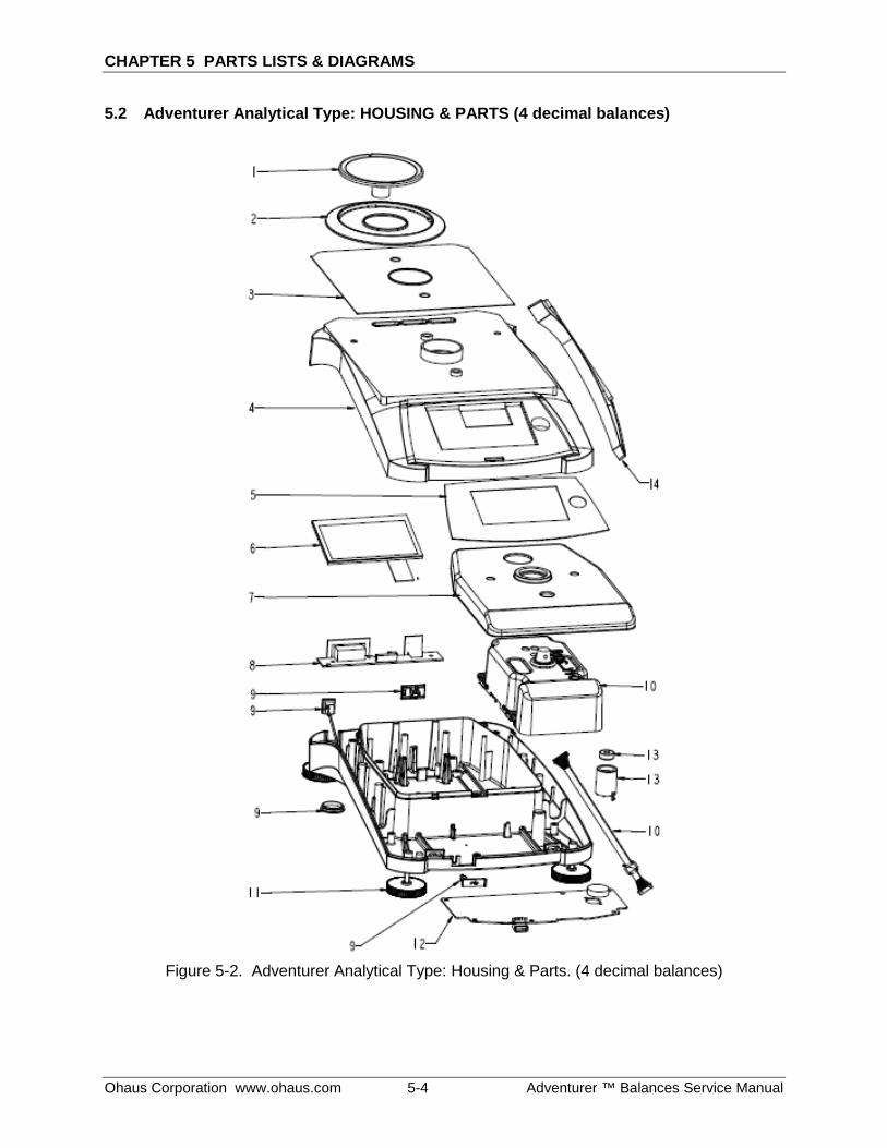
CHAPTER 5 PARTS LISTS & DIAGRAMS
Ohaus Corporation www.ohaus.com 5-4 Adventurer ™ Balances Service Manual
5.2 Adventurer Analytical Type: HOUSING & PARTS (4 decimal balances)
Figure 5-2. Adventurer Analytical Type: Housing & Parts. (4 decimal balances)
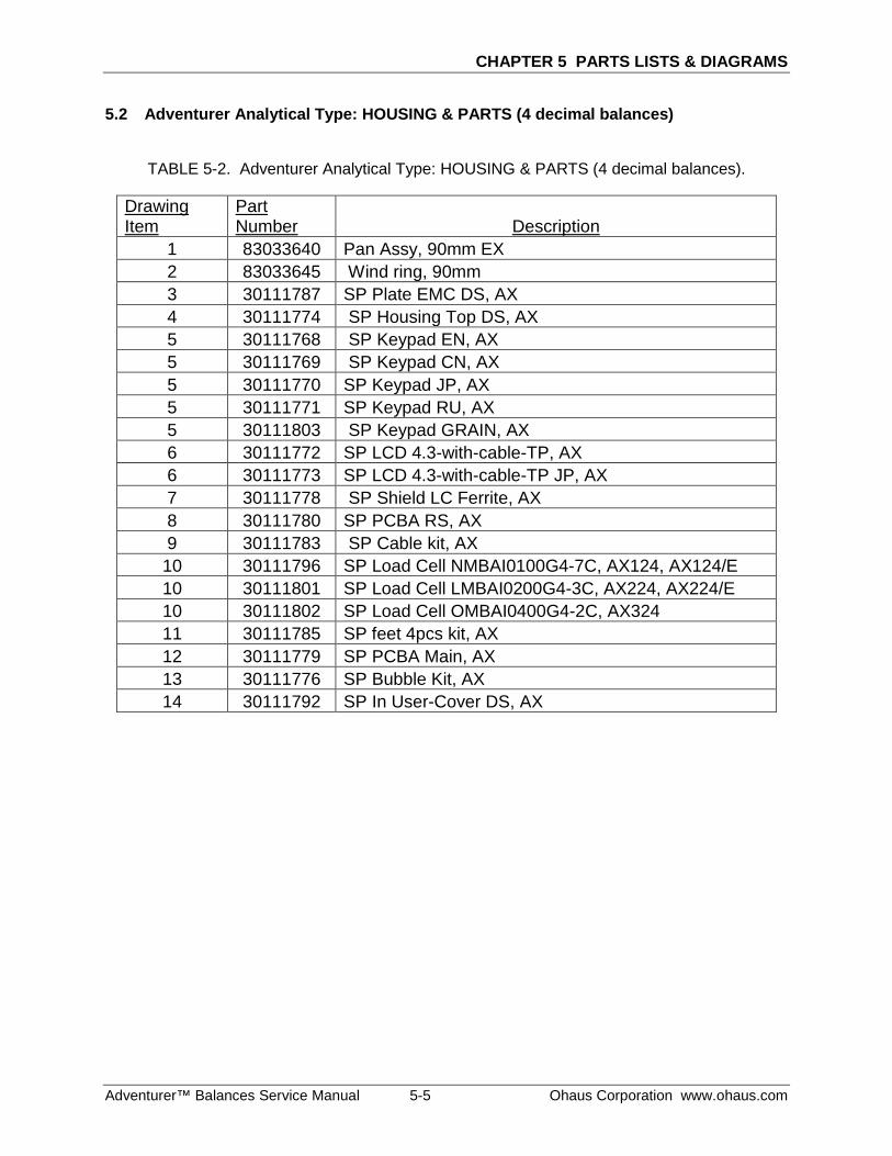
CHAPTER 5 PARTS LISTS & DIAGRAMS
Adventurer™ Balances Service Manual 5-5 Ohaus Corporation www.ohaus.com
5.2 Adventurer Analytical Type: HOUSING & PARTS (4 decimal balances)
TABLE 5-2. Adventurer Analytical Type: HOUSING & PARTS (4 decimal balances).
Drawing Item
Part Number Description
1 83033640 Pan Assy, 90mm EX 2 83033645 Wind ring, 90mm 3 30111787 SP Plate EMC DS, AX 4 30111774 SP Housing Top DS, AX 5 30111768 SP Keypad EN, AX 5 30111769 SP Keypad CN, AX 5 30111770 SP Keypad JP, AX 5 30111771 SP Keypad RU, AX 5 30111803 SP Keypad GRAIN, AX 6 30111772 SP LCD 4.3-with-cable-TP, AX 6 30111773 SP LCD 4.3-with-cable-TP JP, AX 7 30111778 SP Shield LC Ferrite, AX 8 30111780 SP PCBA RS, AX 9 30111783 SP Cable kit, AX 10 30111796 SP Load Cell NMBAI0100G4-7C, AX124, AX124/E 10 30111801 SP Load Cell LMBAI0200G4-3C, AX224, AX224/E 10 30111802 SP Load Cell OMBAI0400G4-2C, AX324 11 30111785 SP feet 4pcs kit, AX 12 30111779 SP PCBA Main, AX 13 30111776 SP Bubble Kit, AX 14 30111792 SP In User-Cover DS, AX
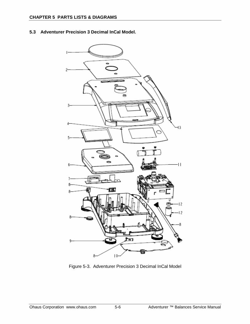
CHAPTER 5 PARTS LISTS & DIAGRAMS
Ohaus Corporation www.ohaus.com 5-6 Adventurer ™ Balances Service Manual
5.3 Adventurer Precision 3 Decimal InCal Model.
Figure 5-3. Adventurer Precision 3 Decimal InCal Model

CHAPTER 5 PARTS LISTS & DIAGRAMS
Adventurer™ Balances Service Manual 5-7 Ohaus Corporation www.ohaus.com
5.3 Adventurer Precision 3 Decimal InCal Model.
TABLE 5-3. Adventurer Precision 3 Decimal InCal Model.
Drawing Item
Part Number Description
1 30111793 SP Assembly Pan 130mm, AX 2 30111787 SP Plate EMC DS, AX 3 30111774 SP Housing Top DS, AX 4 30111768 SP Keypad EN, AX 4 30111769 SP Keypad CN, AX 4 30111770 SP Keypad JP, AX 4 30111771 SP Keypad RU, AX 4 30111803 SP Keypad GRAIN, AX 5 30111772 SP LCD 4.3-with-cable-TP, AX 5 30111773 SP LCD 4.3-with-cable-TP JP, AX 6 30111778 SP Shield LC Ferrite, AX 7 30111780 SP PCBA RS, AX 8 30111783 SP Cable kit, AX 9 30111785 SP feet 4pcs kit, AX 10 30111779 SP PCBA Main, AX 11 30042879 IntCal drive with cable IntCal drive (without weights) 12 30111776 SP Bubble Kit, AX 13 30111792 SP In User-Cover DS, AX

CHAPTER 5 PARTS LISTS & DIAGRAMS
Ohaus Corporation www.ohaus.com 5-8 Adventurer ™ Balances Service Manual
5.4 Adventurer Precision Conventional MFR Load Cell 3 Decimal InCal Model.
Figure 5-4. Conventional MFR Load Cell 3 Decimal InCal Model.
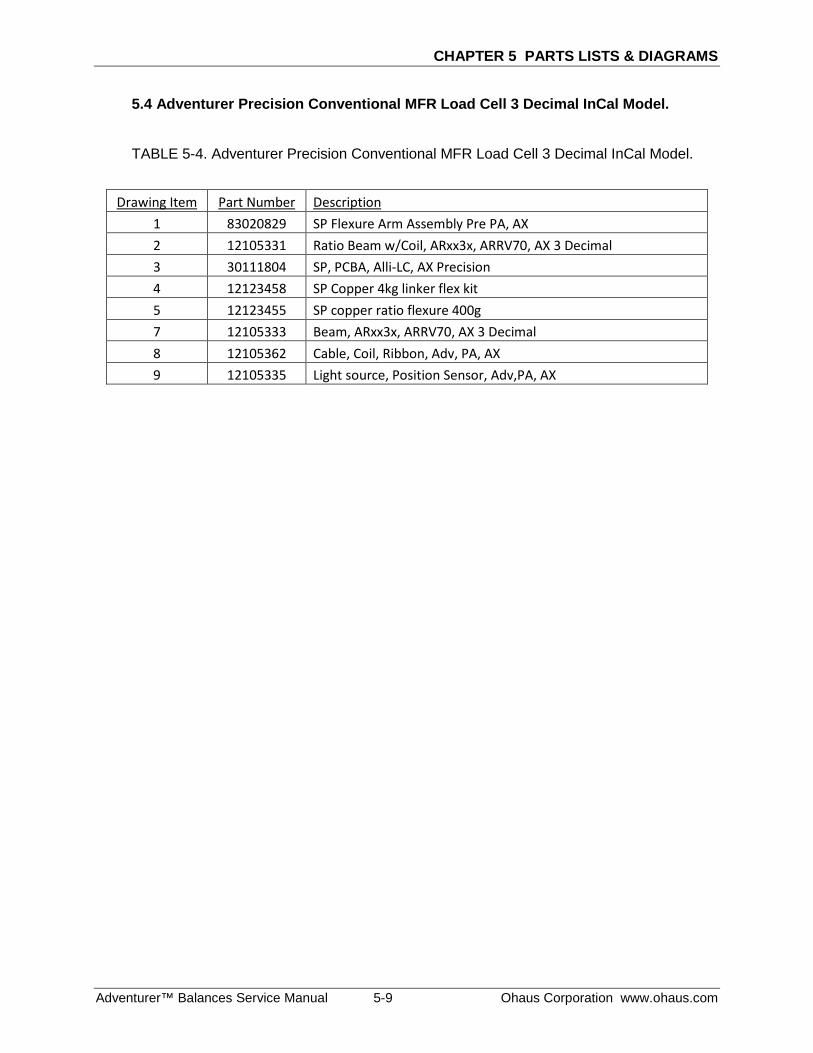
CHAPTER 5 PARTS LISTS & DIAGRAMS
Adventurer™ Balances Service Manual 5-9 Ohaus Corporation www.ohaus.com
5.4 Adventurer Precision Conventional MFR Load Cell 3 Decimal InCal Model.
TABLE 5-4. Adventurer Precision Conventional MFR Load Cell 3 Decimal InCal Model.
Drawing Item Part Number Description
1 83020829 SP Flexure Arm Assembly Pre PA, AX 2 12105331 Ratio Beam w/Coil, ARxx3x, ARRV70, AX 3 Decimal 3 30111804 SP, PCBA, Alli-LC, AX Precision 4 12123458 SP Copper 4kg linker flex kit 5 12123455 SP copper ratio flexure 400g 7 12105333 Beam, ARxx3x, ARRV70, AX 3 Decimal 8 12105362 Cable, Coil, Ribbon, Adv, PA, AX 9 12105335 Light source, Position Sensor, Adv,PA, AX
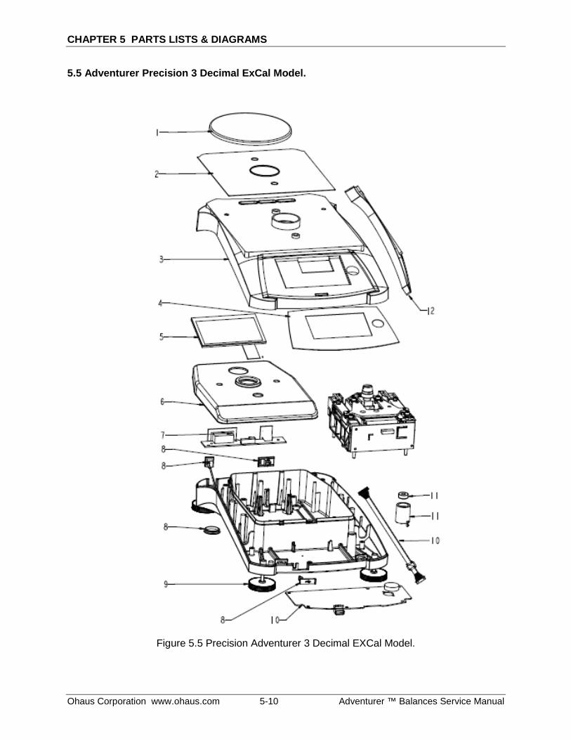
CHAPTER 5 PARTS LISTS & DIAGRAMS
Ohaus Corporation www.ohaus.com 5-10 Adventurer ™ Balances Service Manual
5.5 Adventurer Precision 3 Decimal ExCal Model.
Figure 5.5 Precision Adventurer 3 Decimal EXCal Model.
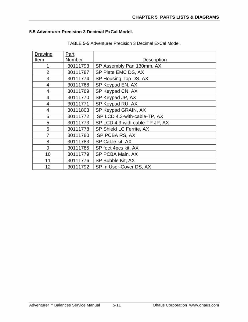
CHAPTER 5 PARTS LISTS & DIAGRAMS
Adventurer™ Balances Service Manual 5-11 Ohaus Corporation www.ohaus.com
5.5 Adventurer Precision 3 Decimal ExCal Model.
TABLE 5-5 Adventurer Precision 3 Decimal ExCal Model.
Drawing Item
Part Number Description
1 30111793 SP Assembly Pan 130mm, AX 2 30111787 SP Plate EMC DS, AX 3 30111774 SP Housing Top DS, AX 4 30111768 SP Keypad EN, AX 4 30111769 SP Keypad CN, AX 4 30111770 SP Keypad JP, AX 4 30111771 SP Keypad RU, AX 4 30111803 SP Keypad GRAIN, AX 5 30111772 SP LCD 4.3-with-cable-TP, AX 5 30111773 SP LCD 4.3-with-cable-TP JP, AX 6 30111778 SP Shield LC Ferrite, AX 7 30111780 SP PCBA RS, AX 8 30111783 SP Cable kit, AX 9 30111785 SP feet 4pcs kit, AX 10 30111779 SP PCBA Main, AX 11 30111776 SP Bubble Kit, AX 12 30111792 SP In User-Cover DS, AX
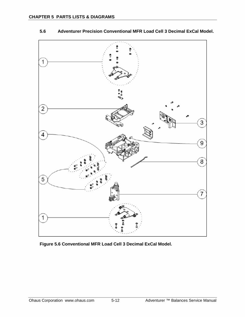
CHAPTER 5 PARTS LISTS & DIAGRAMS
Ohaus Corporation www.ohaus.com 5-12 Adventurer ™ Balances Service Manual
5.6 Adventurer Precision Conventional MFR Load Cell 3 Decimal ExCal Model.
Figure 5.6 Conventional MFR Load Cell 3 Decimal ExCal Model.
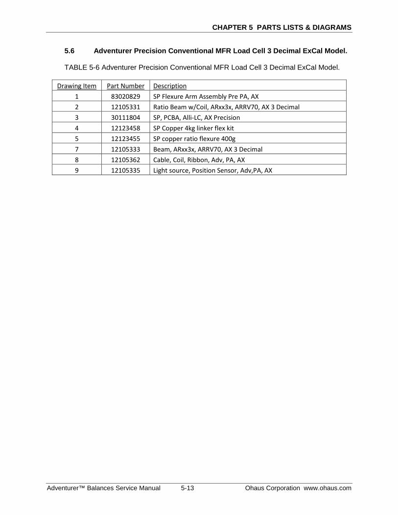
CHAPTER 5 PARTS LISTS & DIAGRAMS
Adventurer™ Balances Service Manual 5-13 Ohaus Corporation www.ohaus.com
5.6 Adventurer Precision Conventional MFR Load Cell 3 Decimal ExCal Model.
TABLE 5-6 Adventurer Precision Conventional MFR Load Cell 3 Decimal ExCal Model.
Drawing Item Part Number Description 1 83020829 SP Flexure Arm Assembly Pre PA, AX 2 12105331 Ratio Beam w/Coil, ARxx3x, ARRV70, AX 3 Decimal 3 30111804 SP, PCBA, Alli-LC, AX Precision 4 12123458 SP Copper 4kg linker flex kit 5 12123455 SP copper ratio flexure 400g 7 12105333 Beam, ARxx3x, ARRV70, AX 3 Decimal 8 12105362 Cable, Coil, Ribbon, Adv, PA, AX 9 12105335 Light source, Position Sensor, Adv,PA, AX
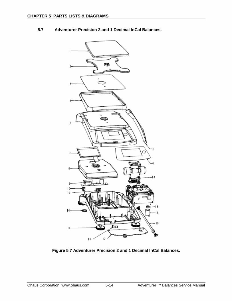
CHAPTER 5 PARTS LISTS & DIAGRAMS
Ohaus Corporation www.ohaus.com 5-14 Adventurer ™ Balances Service Manual
5.7 Adventurer Precision 2 and 1 Decimal InCal Balances.
Figure 5.7 Adventurer Precision 2 and 1 Decimal InCal Balances.
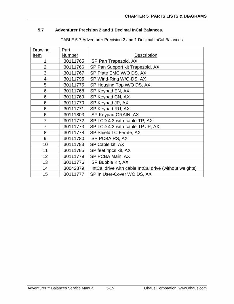
CHAPTER 5 PARTS LISTS & DIAGRAMS
Adventurer™ Balances Service Manual 5-15 Ohaus Corporation www.ohaus.com
5.7 Adventurer Precision 2 and 1 Decimal InCal Balances.
TABLE 5-7 Adventurer Precision 2 and 1 Decimal InCal Balances.
Drawing Item
Part Number Description
1 30111765 SP Pan Trapezoid, AX 2 30111766 SP Pan Support kit Trapezoid, AX 3 30111767 SP Plate EMC W/O DS, AX 4 30111795 SP Wind-Ring W/O-DS, AX 5 30111775 SP Housing Top W/O DS, AX 6 30111768 SP Keypad EN, AX 6 30111769 SP Keypad CN, AX 6 30111770 SP Keypad JP, AX 6 30111771 SP Keypad RU, AX 6 30111803 SP Keypad GRAIN, AX 7 30111772 SP LCD 4.3-with-cable-TP, AX 7 30111773 SP LCD 4.3-with-cable-TP JP, AX 8 30111778 SP Shield LC Ferrite, AX 9 30111780 SP PCBA RS, AX 10 30111783 SP Cable kit, AX 11 30111785 SP feet 4pcs kit, AX 12 30111779 SP PCBA Main, AX 13 30111776 SP Bubble Kit, AX 14 30042879 IntCal drive with cable IntCal drive (without weights) 15 30111777 SP In User-Cover WO DS, AX

CHAPTER 5 PARTS LISTS & DIAGRAMS
Ohaus Corporation www.ohaus.com 5-16 Adventurer ™ Balances Service Manual
5.8 Adventurer Precision Conventional MFR Load Cell 2 and 1 Decimal InCal Model.
Figure 5.8 Conventional MFR Load Cell 2 and 1 Decimal InCal Model.
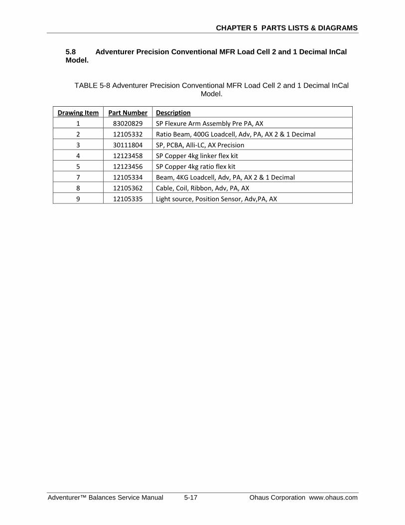
CHAPTER 5 PARTS LISTS & DIAGRAMS
Adventurer™ Balances Service Manual 5-17 Ohaus Corporation www.ohaus.com
5.8 Adventurer Precision Conventional MFR Load Cell 2 and 1 Decimal InCal Model.
TABLE 5-8 Adventurer Precision Conventional MFR Load Cell 2 and 1 Decimal InCal Model.
Drawing Item Part Number Description
1 83020829 SP Flexure Arm Assembly Pre PA, AX 2 12105332 Ratio Beam, 400G Loadcell, Adv, PA, AX 2 & 1 Decimal 3 30111804 SP, PCBA, Alli-LC, AX Precision 4 12123458 SP Copper 4kg linker flex kit 5 12123456 SP Copper 4kg ratio flex kit 7 12105334 Beam, 4KG Loadcell, Adv, PA, AX 2 & 1 Decimal 8 12105362 Cable, Coil, Ribbon, Adv, PA, AX 9 12105335 Light source, Position Sensor, Adv,PA, AX
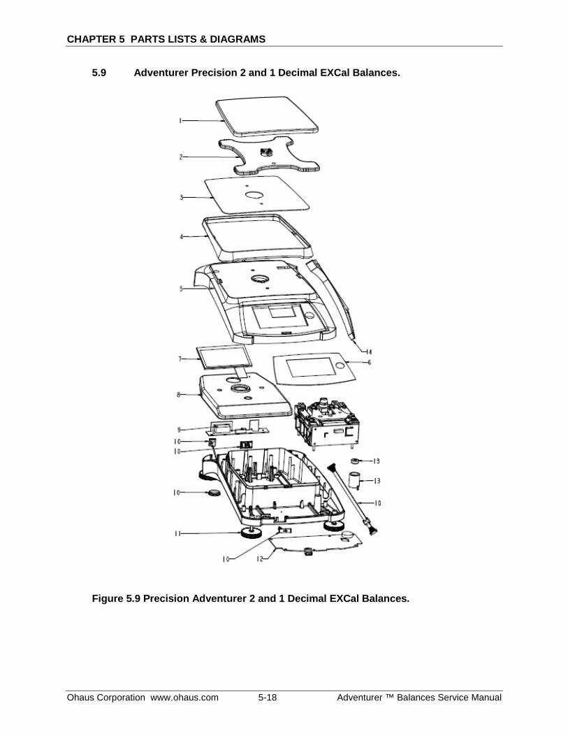
CHAPTER 5 PARTS LISTS & DIAGRAMS
Ohaus Corporation www.ohaus.com 5-18 Adventurer ™ Balances Service Manual
5.9 Adventurer Precision 2 and 1 Decimal EXCal Balances.
Figure 5.9 Precision Adventurer 2 and 1 Decimal EXCal Balances.
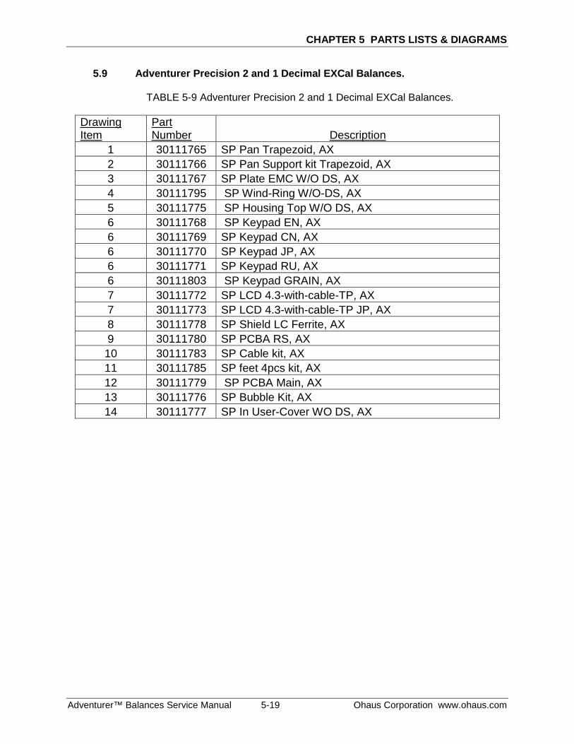
CHAPTER 5 PARTS LISTS & DIAGRAMS
Adventurer™ Balances Service Manual 5-19 Ohaus Corporation www.ohaus.com
5.9 Adventurer Precision 2 and 1 Decimal EXCal Balances.
TABLE 5-9 Adventurer Precision 2 and 1 Decimal EXCal Balances.
Drawing Item
Part Number Description
1 30111765 SP Pan Trapezoid, AX 2 30111766 SP Pan Support kit Trapezoid, AX 3 30111767 SP Plate EMC W/O DS, AX 4 30111795 SP Wind-Ring W/O-DS, AX 5 30111775 SP Housing Top W/O DS, AX 6 30111768 SP Keypad EN, AX 6 30111769 SP Keypad CN, AX 6 30111770 SP Keypad JP, AX 6 30111771 SP Keypad RU, AX 6 30111803 SP Keypad GRAIN, AX 7 30111772 SP LCD 4.3-with-cable-TP, AX 7 30111773 SP LCD 4.3-with-cable-TP JP, AX 8 30111778 SP Shield LC Ferrite, AX 9 30111780 SP PCBA RS, AX 10 30111783 SP Cable kit, AX 11 30111785 SP feet 4pcs kit, AX 12 30111779 SP PCBA Main, AX 13 30111776 SP Bubble Kit, AX 14 30111777 SP In User-Cover WO DS, AX
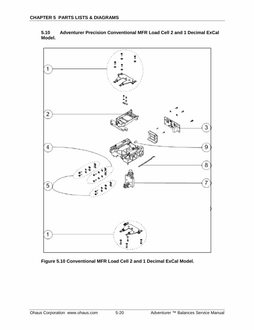
CHAPTER 5 PARTS LISTS & DIAGRAMS
Ohaus Corporation www.ohaus.com 5-20 Adventurer ™ Balances Service Manual
5.10 Adventurer Precision Conventional MFR Load Cell 2 and 1 Decimal ExCal Model.
Figure 5.10 Conventional MFR Load Cell 2 and 1 Decimal ExCal Model.
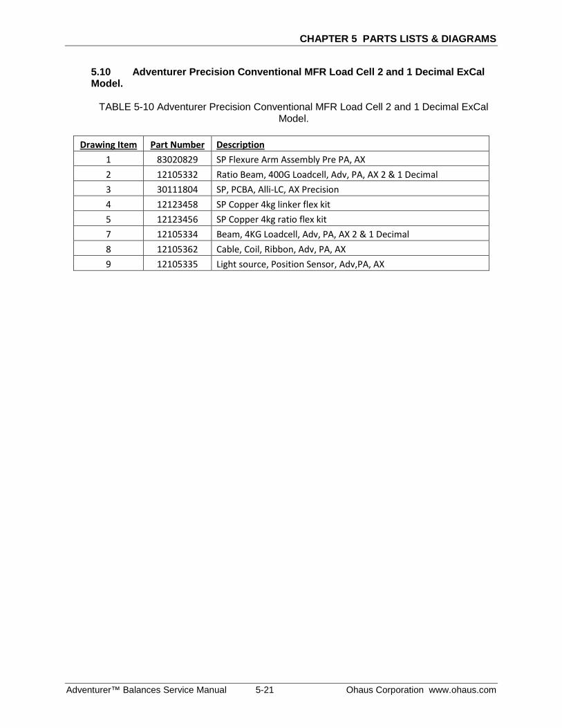
CHAPTER 5 PARTS LISTS & DIAGRAMS
Adventurer™ Balances Service Manual 5-21 Ohaus Corporation www.ohaus.com
5.10 Adventurer Precision Conventional MFR Load Cell 2 and 1 Decimal ExCal Model.
TABLE 5-10 Adventurer Precision Conventional MFR Load Cell 2 and 1 Decimal ExCal
Model.
Drawing Item Part Number Description 1 83020829 SP Flexure Arm Assembly Pre PA, AX 2 12105332 Ratio Beam, 400G Loadcell, Adv, PA, AX 2 & 1 Decimal 3 30111804 SP, PCBA, Alli-LC, AX Precision 4 12123458 SP Copper 4kg linker flex kit 5 12123456 SP Copper 4kg ratio flex kit 7 12105334 Beam, 4KG Loadcell, Adv, PA, AX 2 & 1 Decimal 8 12105362 Cable, Coil, Ribbon, Adv, PA, AX 9 12105335 Light source, Position Sensor, Adv,PA, AX
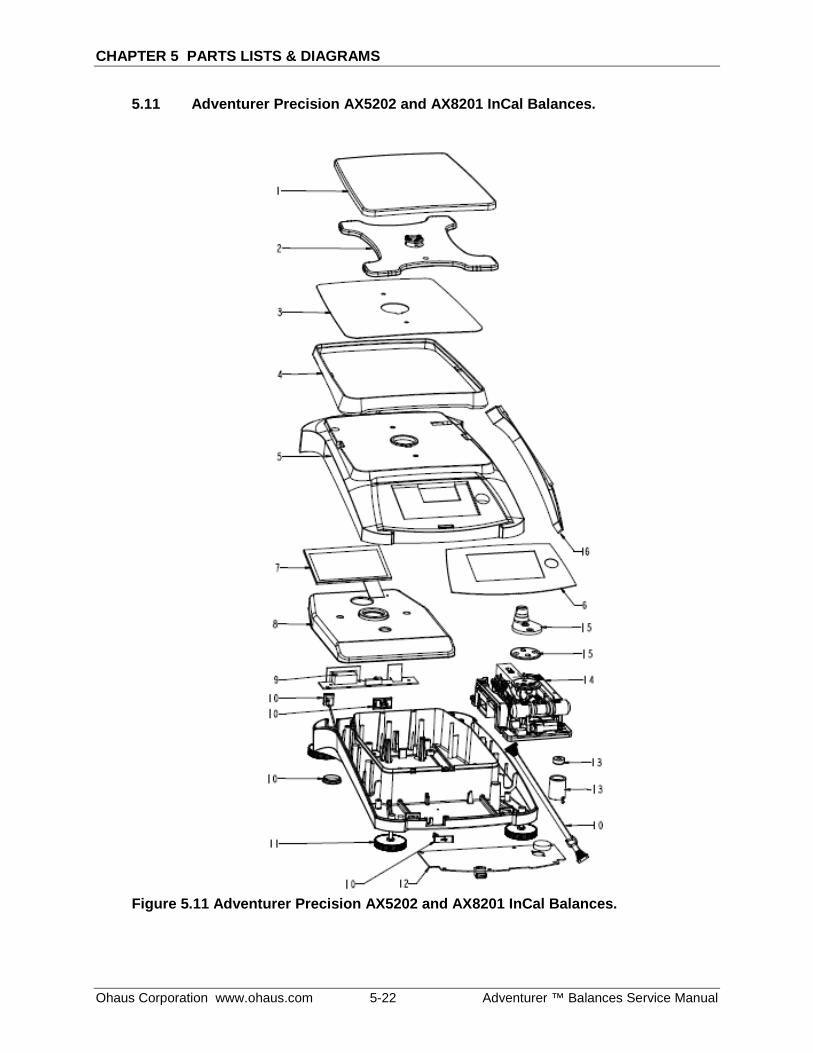
CHAPTER 5 PARTS LISTS & DIAGRAMS
Ohaus Corporation www.ohaus.com 5-22 Adventurer ™ Balances Service Manual
5.11 Adventurer Precision AX5202 and AX8201 InCal Balances.
Figure 5.11 Adventurer Precision AX5202 and AX8201 InCal Balances.
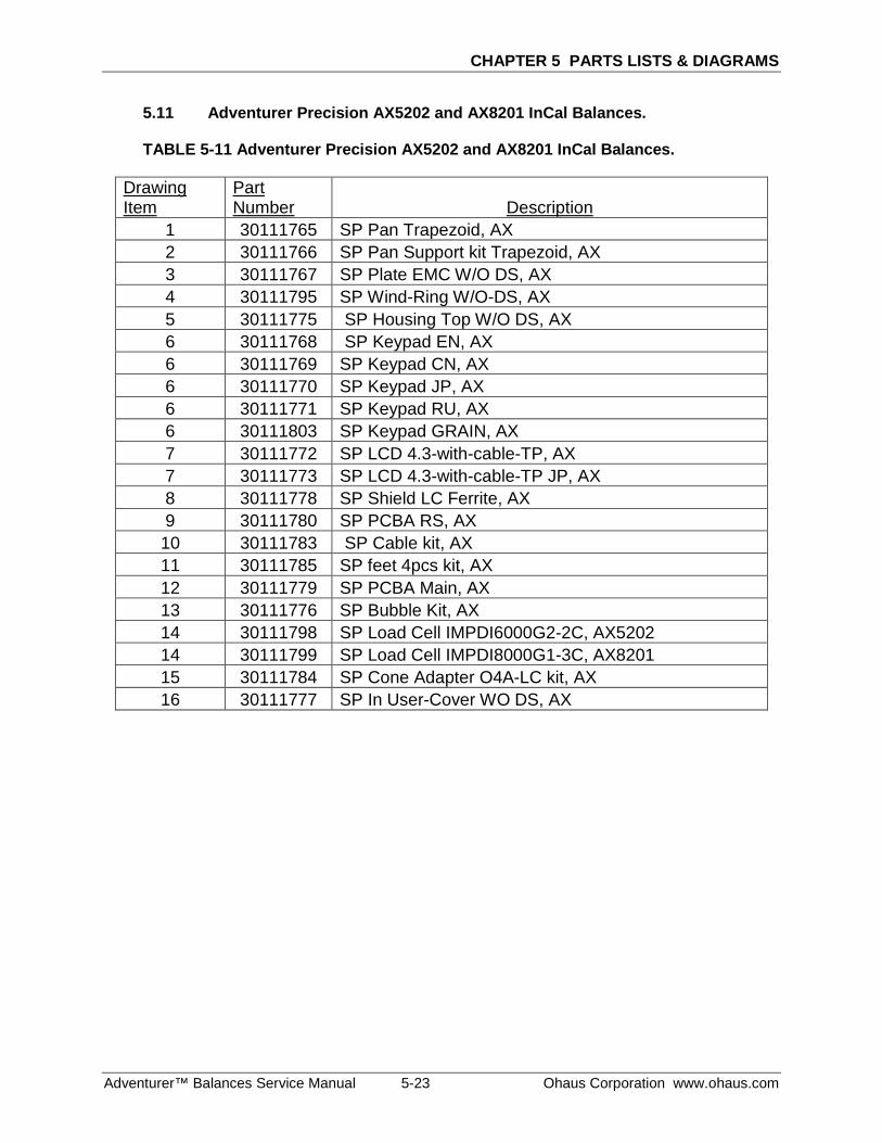
CHAPTER 5 PARTS LISTS & DIAGRAMS
Adventurer™ Balances Service Manual 5-23 Ohaus Corporation www.ohaus.com
5.11 Adventurer Precision AX5202 and AX8201 InCal Balances.
TABLE 5-11 Adventurer Precision AX5202 and AX8201 InCal Balances.
Drawing Item
Part Number Description
1 30111765 SP Pan Trapezoid, AX 2 30111766 SP Pan Support kit Trapezoid, AX 3 30111767 SP Plate EMC W/O DS, AX 4 30111795 SP Wind-Ring W/O-DS, AX 5 30111775 SP Housing Top W/O DS, AX 6 30111768 SP Keypad EN, AX 6 30111769 SP Keypad CN, AX 6 30111770 SP Keypad JP, AX 6 30111771 SP Keypad RU, AX 6 30111803 SP Keypad GRAIN, AX 7 30111772 SP LCD 4.3-with-cable-TP, AX 7 30111773 SP LCD 4.3-with-cable-TP JP, AX 8 30111778 SP Shield LC Ferrite, AX 9 30111780 SP PCBA RS, AX 10 30111783 SP Cable kit, AX 11 30111785 SP feet 4pcs kit, AX 12 30111779 SP PCBA Main, AX 13 30111776 SP Bubble Kit, AX 14 30111798 SP Load Cell IMPDI6000G2-2C, AX5202 14 30111799 SP Load Cell IMPDI8000G1-3C, AX8201 15 30111784 SP Cone Adapter O4A-LC kit, AX 16 30111777 SP In User-Cover WO DS, AX
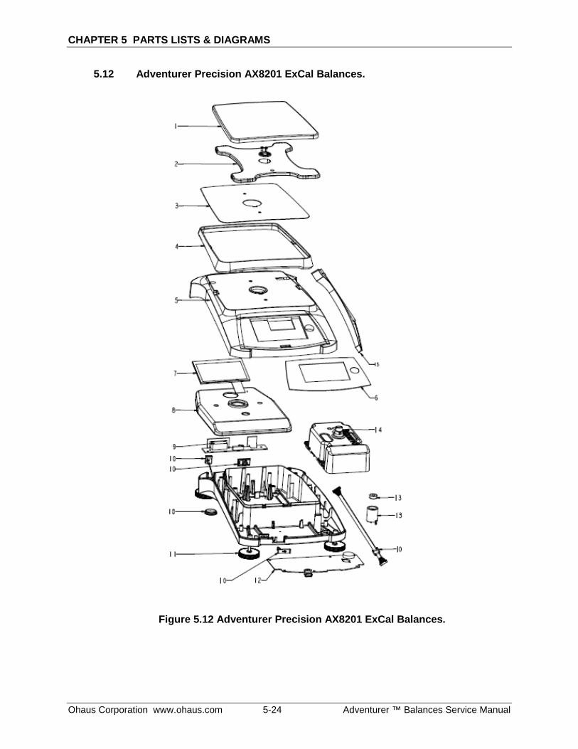
CHAPTER 5 PARTS LISTS & DIAGRAMS
Ohaus Corporation www.ohaus.com 5-24 Adventurer ™ Balances Service Manual
5.12 Adventurer Precision AX8201 ExCal Balances.
Figure 5.12 Adventurer Precision AX8201 ExCal Balances.
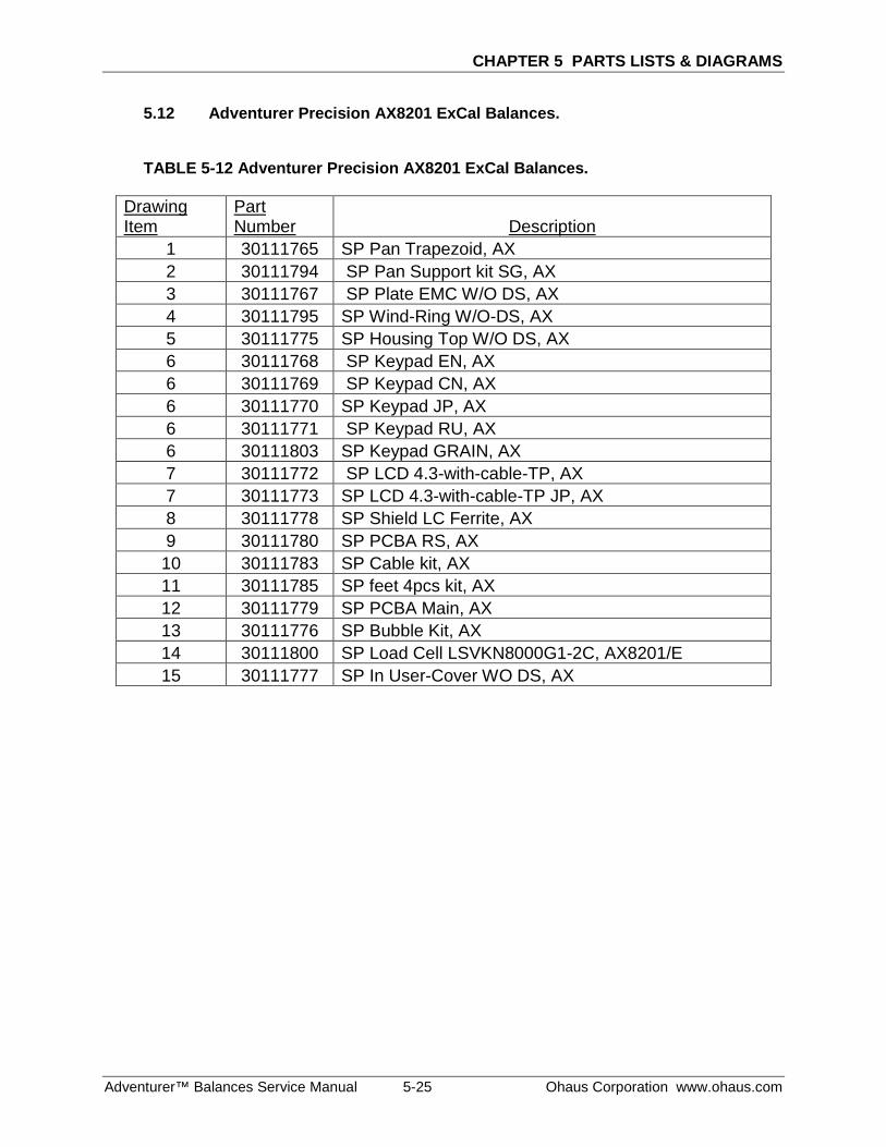
CHAPTER 5 PARTS LISTS & DIAGRAMS
Adventurer™ Balances Service Manual 5-25 Ohaus Corporation www.ohaus.com
5.12 Adventurer Precision AX8201 ExCal Balances.
TABLE 5-12 Adventurer Precision AX8201 ExCal Balances.
Drawing Item
Part Number Description
1 30111765 SP Pan Trapezoid, AX 2 30111794 SP Pan Support kit SG, AX 3 30111767 SP Plate EMC W/O DS, AX 4 30111795 SP Wind-Ring W/O-DS, AX 5 30111775 SP Housing Top W/O DS, AX 6 30111768 SP Keypad EN, AX 6 30111769 SP Keypad CN, AX 6 30111770 SP Keypad JP, AX 6 30111771 SP Keypad RU, AX 6 30111803 SP Keypad GRAIN, AX 7 30111772 SP LCD 4.3-with-cable-TP, AX 7 30111773 SP LCD 4.3-with-cable-TP JP, AX 8 30111778 SP Shield LC Ferrite, AX 9 30111780 SP PCBA RS, AX 10 30111783 SP Cable kit, AX 11 30111785 SP feet 4pcs kit, AX 12 30111779 SP PCBA Main, AX 13 30111776 SP Bubble Kit, AX 14 30111800 SP Load Cell LSVKN8000G1-2C, AX8201/E 15 30111777 SP In User-Cover WO DS, AX
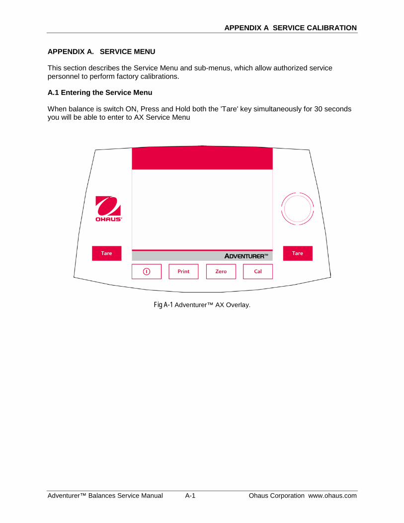
APPENDIX A SERVICE CALIBRATION
Adventurer™ Balances Service Manual A-1 Ohaus Corporation www.ohaus.com
APPENDIX A. SERVICE MENU
This section describes the Service Menu and sub-menus, which allow authorized service personnel to perform factory calibrations.
A.1 Entering the Service Menu
When balance is switch ON, Press and Hold both the 'Tare' key simultaneously for 30 seconds you will be able to enter to AX Service Menu
Fig A-1 Adventurer™ AX Overlay.
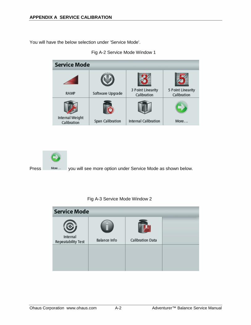
APPENDIX A SERVICE CALIBRATION
Ohaus Corporation www.ohaus.com A-2 Adventurer™ Balance Service Manual
You will have the below selection under 'Service Mode'.
Fig A-2 Service Mode Window 1
Press you will see more option under Service Mode as shown below.
Fig A-3 Service Mode Window 2
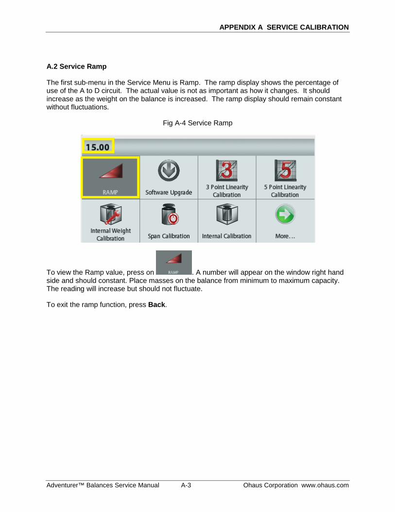
APPENDIX A SERVICE CALIBRATION
Adventurer™ Balances Service Manual A-3 Ohaus Corporation www.ohaus.com
A.2 Service Ramp
The first sub-menu in the Service Menu is Ramp. The ramp display shows the percentage of use of the A to D circuit. The actual value is not as important as how it changes. It should increase as the weight on the balance is increased. The ramp display should remain constant without fluctuations.
Fig A-4 Service Ramp
To view the Ramp value, press on . A number will appear on the window right hand side and should constant. Place masses on the balance from minimum to maximum capacity. The reading will increase but should not fluctuate.
To exit the ramp function, press Back.
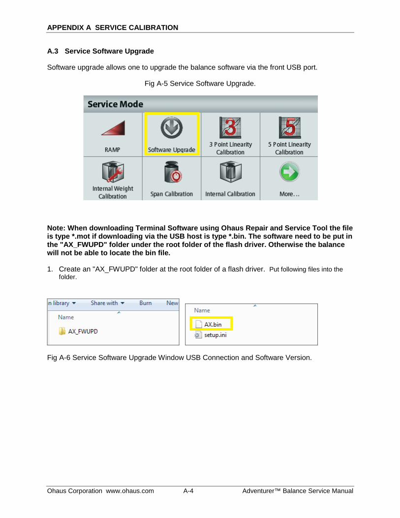
APPENDIX A SERVICE CALIBRATION
Ohaus Corporation www.ohaus.com A-4 Adventurer™ Balance Service Manual
A.3 Service Software Upgrade
Software upgrade allows one to upgrade the balance software via the front USB port.
Fig A-5 Service Software Upgrade.
Note: When downloading Terminal Software using Ohaus Repair and Service Tool the file is type *.mot if downloading via the USB host is type *.bin. The software need to be put in the "AX_FWUPD" folder under the root folder of the flash driver. Otherwise the balance will not be able to locate the bin file.
1. Create an "AX_FWUPD" folder at the root folder of a flash driver. Put following files into the folder.
Fig A-6 Service Software Upgrade Window USB Connection and Software Version.
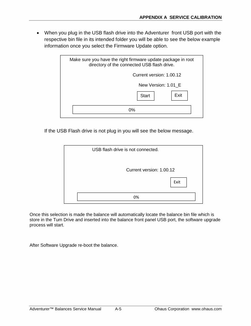
APPENDIX A SERVICE CALIBRATION
Adventurer™ Balances Service Manual A-5 Ohaus Corporation www.ohaus.com
• When you plug in the USB flash drive into the Adventurer front USB port with the respective bin file in its intended folder you will be able to see the below example information once you select the Firmware Update option. If the USB Flash drive is not plug in you will see the below message.
Once this selection is made the balance will automatically locate the balance bin file which is store in the Tum Drive and inserted into the balance front panel USB port, the software upgrade process will start.
After Software Upgrade re-boot the balance.
Make sure you have the right firmware update package in root directory of the connected USB flash drive.
Current version: 1.00.12
New Version: 1.01_E
USB flash drive is not connected.
Current version: 1.00.12
Exit
0%
Start Exit
0%
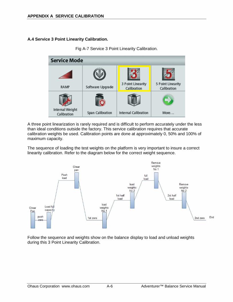
APPENDIX A SERVICE CALIBRATION
Ohaus Corporation www.ohaus.com A-6 Adventurer™ Balance Service Manual
A.4 Service 3 Point Linearity Calibration.
Fig A-7 Service 3 Point Linearity Calibration.
A three point linearization is rarely required and is difficult to perform accurately under the less than ideal conditions outside the factory. This service calibration requires that accurate calibration weights be used. Calibration points are done at approximately 0, 50% and 100% of maximum capacity.
The sequence of loading the test weights on the platform is very important to insure a correct linearity calibration. Refer to the diagram below for the correct weight sequence.
Follow the sequence and weights show on the balance display to load and unload weights during this 3 Point Linearity Calibration.
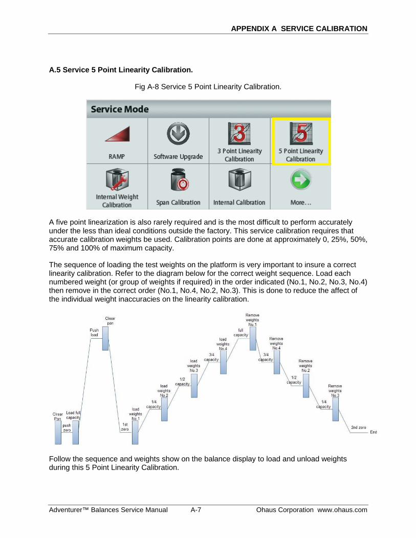
APPENDIX A SERVICE CALIBRATION
Adventurer™ Balances Service Manual A-7 Ohaus Corporation www.ohaus.com
A.5 Service 5 Point Linearity Calibration.
Fig A-8 Service 5 Point Linearity Calibration.
A five point linearization is also rarely required and is the most difficult to perform accurately under the less than ideal conditions outside the factory. This service calibration requires that accurate calibration weights be used. Calibration points are done at approximately 0, 25%, 50%, 75% and 100% of maximum capacity.
The sequence of loading the test weights on the platform is very important to insure a correct linearity calibration. Refer to the diagram below for the correct weight sequence. Load each numbered weight (or group of weights if required) in the order indicated (No.1, No.2, No.3, No.4) then remove in the correct order (No.1, No.4, No.2, No.3). This is done to reduce the affect of the individual weight inaccuracies on the linearity calibration.
Follow the sequence and weights show on the balance display to load and unload weights during this 5 Point Linearity Calibration.
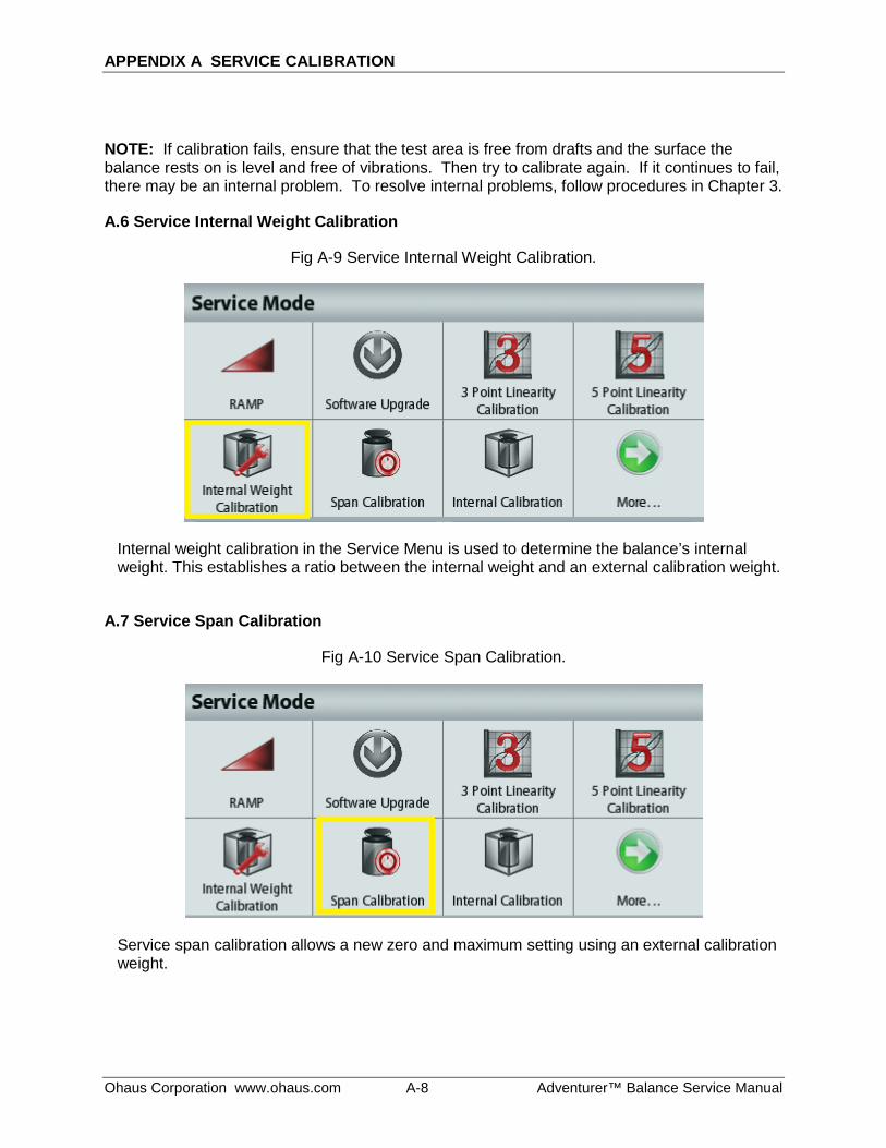
APPENDIX A SERVICE CALIBRATION
Ohaus Corporation www.ohaus.com A-8 Adventurer™ Balance Service Manual
NOTE: If calibration fails, ensure that the test area is free from drafts and the surface the balance rests on is level and free of vibrations. Then try to calibrate again. If it continues to fail, there may be an internal problem. To resolve internal problems, follow procedures in Chapter 3.
A.6 Service Internal Weight Calibration
Fig A-9 Service Internal Weight Calibration.
Internal weight calibration in the Service Menu is used to determine the balance’s internal weight. This establishes a ratio between the internal weight and an external calibration weight.
A.7 Service Span Calibration
Fig A-10 Service Span Calibration.
Service span calibration allows a new zero and maximum setting using an external calibration weight.
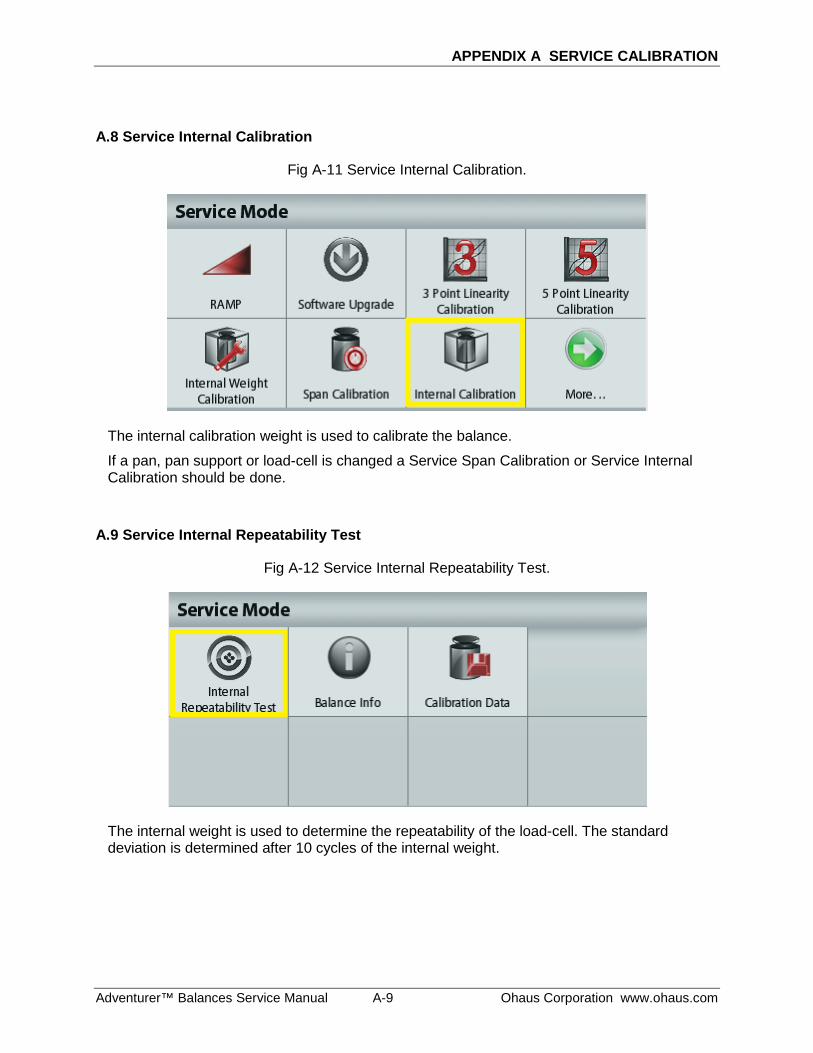
APPENDIX A SERVICE CALIBRATION
Adventurer™ Balances Service Manual A-9 Ohaus Corporation www.ohaus.com
A.8 Service Internal Calibration
Fig A-11 Service Internal Calibration.
The internal calibration weight is used to calibrate the balance.
If a pan, pan support or load-cell is changed a Service Span Calibration or Service Internal Calibration should be done.
A.9 Service Internal Repeatability Test
Fig A-12 Service Internal Repeatability Test.
The internal weight is used to determine the repeatability of the load-cell. The standard deviation is determined after 10 cycles of the internal weight.
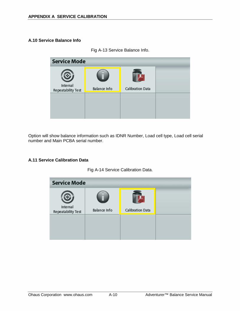
APPENDIX A SERVICE CALIBRATION
Ohaus Corporation www.ohaus.com A-10 Adventurer™ Balance Service Manual
A.10 Service Balance Info
Fig A-13 Service Balance Info.
Option will show balance information such as IDNR Number, Load cell type, Load cell serial number and Main PCBA serial number.
A.11 Service Calibration Data
Fig A-14 Service Calibration Data.
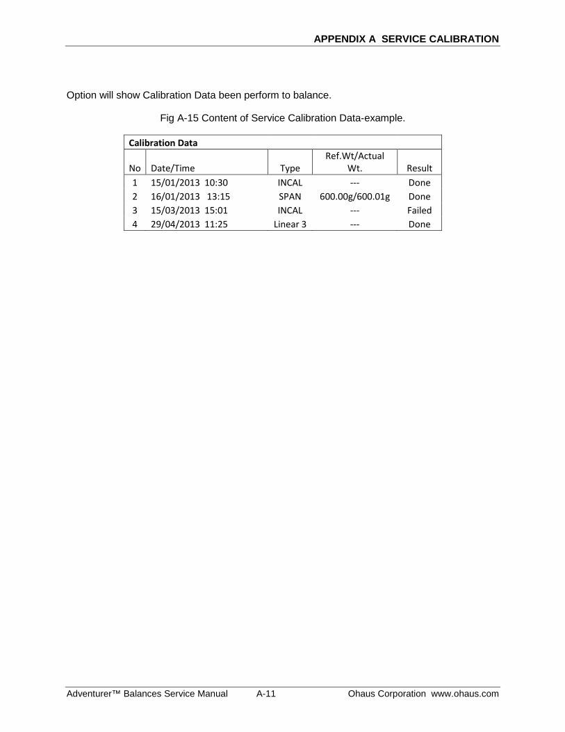
APPENDIX A SERVICE CALIBRATION
Adventurer™ Balances Service Manual A-11 Ohaus Corporation www.ohaus.com
Option will show Calibration Data been perform to balance.
Fig A-15 Content of Service Calibration Data-example.
Calibration Data
No Date/Time Type Ref.Wt/Actual
Wt. Result 1 15/01/2013 10:30 INCAL --- Done 2 16/01/2013 13:15 SPAN 600.00g/600.01g Done 3 15/03/2013 15:01 INCAL --- Failed 4 29/04/2013 11:25 Linear 3 --- Done
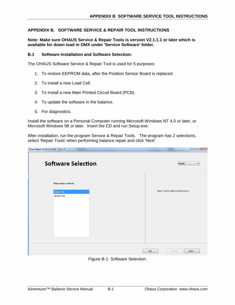
APPENDIX B SOFTWARE SERVICE TOOL INSTRUCTIONS
Adventurer™ Balance Service Manual B-1 Ohaus Corporation www.ohaus.com
APPENDIX B. SOFTWARE SERVICE & REPAIR TOOL INSTRUCTIONS Note: Make sure OHAUS Service & Repair Tools is version V2.1.1.1 or later which is available for down load in DMX under 'Service Software' folder. B.1 Software Installation and Software Selection: The OHAUS Software Service & Repair Tool is used for 5 purposes:
1. To restore EEPROM data, after the Position Sensor Board is replaced.
2. To install a new Load Cell.
3. To install a new Main Printed Circuit Board (PCB).
4. To update the software in the balance.
5. For diagnostics.
Install the software on a Personal Computer running Microsoft Windows NT 4.0 or later, or Microsoft Windows 98 or later. Insert the CD and run Setup.exe. After installation, run the program Service & Repair Tools. The program has 2 selections, select 'Repair Tools' when performing balance repair and click 'Next'.
Figure B-1. Software Selection.
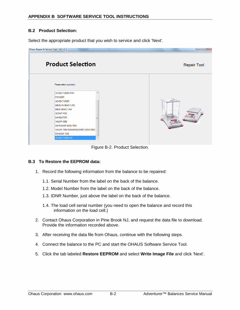
APPENDIX B SOFTWARE SERVICE TOOL INSTRUCTIONS
Ohaus Corporation www.ohaus.com B-2 Adventurer™ Balances Service Manual
B.2 Product Selection: Select the appropriate product that you wish to service and click 'Next'.
Figure B-2. Product Selection.
B.3 To Restore the EEPROM data:
1. Record the following information from the balance to be repaired:
1.1. Serial Number from the label on the back of the balance.
1.2. Model Number from the label on the back of the balance.
1.3. IDNR Number, just above the label on the back of the balance.
1.4. The load cell serial number (you need to open the balance and record this information on the load cell.)
2. Contact Ohaus Corporation in Pine Brook NJ, and request the data file to download. Provide the information recorded above.
3. After receiving the data file from Ohaus, continue with the following steps.
4. Connect the balance to the PC and start the OHAUS Software Service Tool.
5. Click the tab labeled Restore EEPROM and select Write Image File and click 'Next'.
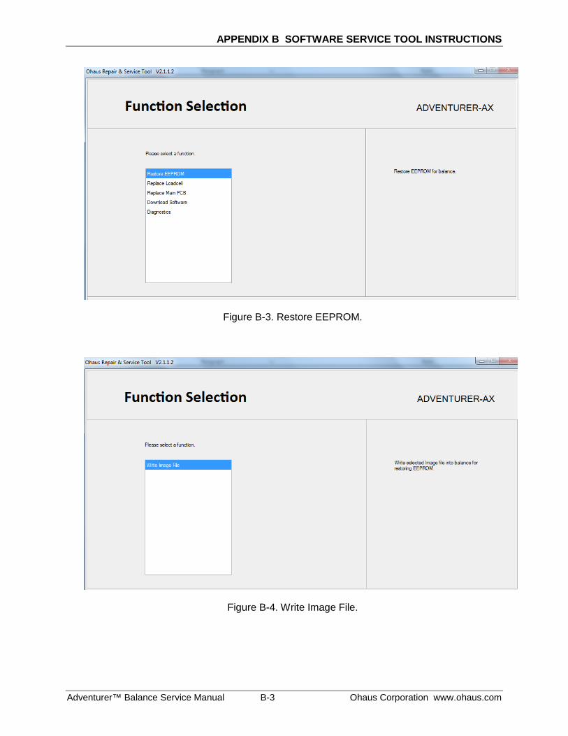
APPENDIX B SOFTWARE SERVICE TOOL INSTRUCTIONS
Adventurer™ Balance Service Manual B-3 Ohaus Corporation www.ohaus.com
Figure B-3. Restore EEPROM.
Figure B-4. Write Image File.
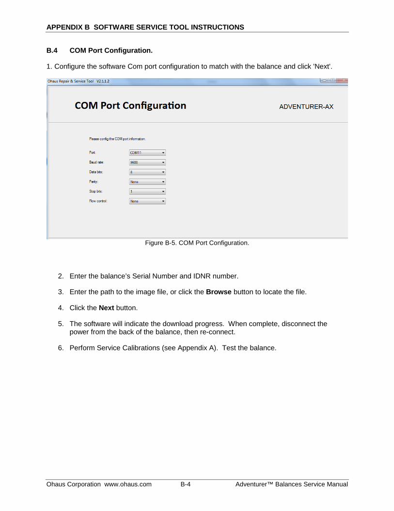
APPENDIX B SOFTWARE SERVICE TOOL INSTRUCTIONS
Ohaus Corporation www.ohaus.com B-4 Adventurer™ Balances Service Manual
B.4 COM Port Configuration.
1. Configure the software Com port configuration to match with the balance and click 'Next'.
Figure B-5. COM Port Configuration.
2. Enter the balance’s Serial Number and IDNR number.
3. Enter the path to the image file, or click the Browse button to locate the file.
4. Click the Next button.
5. The software will indicate the download progress. When complete, disconnect the power from the back of the balance, then re-connect.
6. Perform Service Calibrations (see Appendix A). Test the balance.
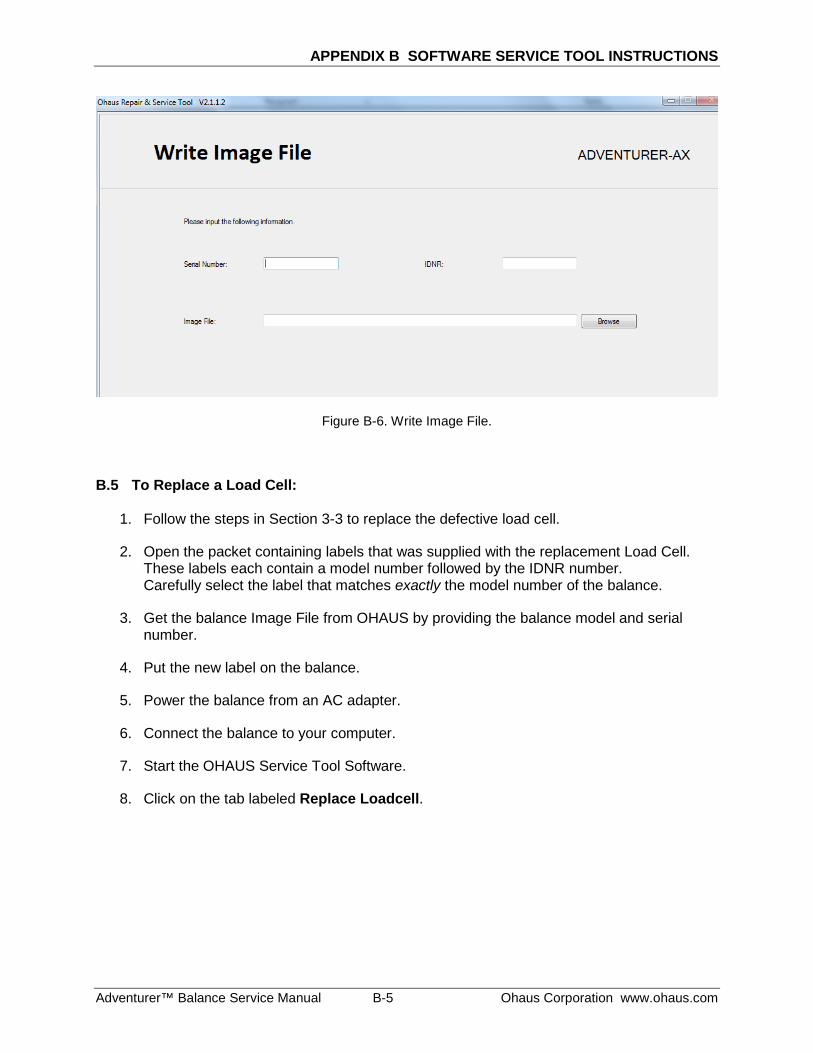
APPENDIX B SOFTWARE SERVICE TOOL INSTRUCTIONS
Adventurer™ Balance Service Manual B-5 Ohaus Corporation www.ohaus.com
Figure B-6. Write Image File.
B.5 To Replace a Load Cell:
1. Follow the steps in Section 3-3 to replace the defective load cell.
2. Open the packet containing labels that was supplied with the replacement Load Cell. These labels each contain a model number followed by the IDNR number. Carefully select the label that matches exactly the model number of the balance.
3. Get the balance Image File from OHAUS by providing the balance model and serial number.
4. Put the new label on the balance.
5. Power the balance from an AC adapter.
6. Connect the balance to your computer.
7. Start the OHAUS Service Tool Software.
8. Click on the tab labeled Replace Loadcell.
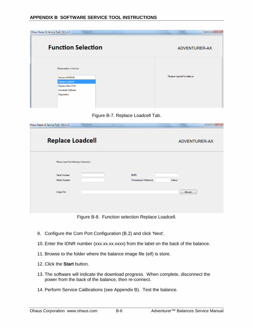
APPENDIX B SOFTWARE SERVICE TOOL INSTRUCTIONS
Ohaus Corporation www.ohaus.com B-6 Adventurer™ Balances Service Manual
Figure B-7. Replace Loadcell Tab.
Figure B-8. Function selection Replace Loadcell.
9. Configure the Com Port Configuration (B.2) and click 'Next'.
10. Enter the IDNR number (xxx.xx.xx.xxxx) from the label on the back of the balance.
11. Browse to the folder where the balance image file (eif) is store.
12. Click the Start button.
13. The software will indicate the download progress. When complete, disconnect the power from the back of the balance, then re-connect.
14. Perform Service Calibrations (see Appendix B). Test the balance.
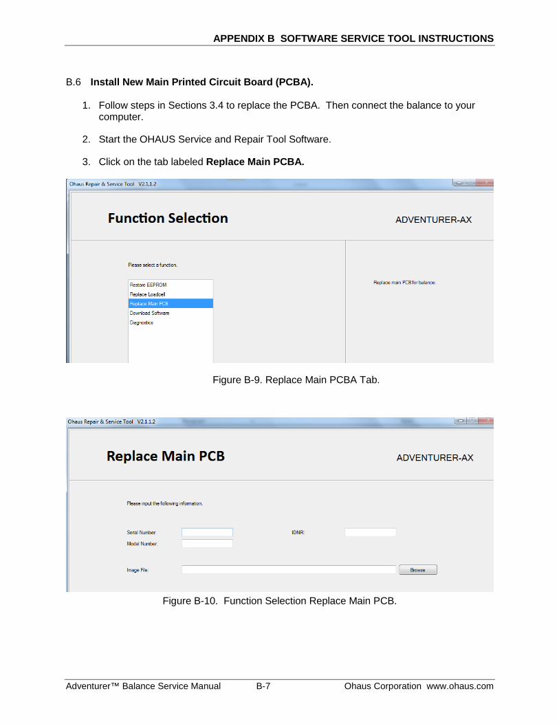
APPENDIX B SOFTWARE SERVICE TOOL INSTRUCTIONS
Adventurer™ Balance Service Manual B-7 Ohaus Corporation www.ohaus.com
B.6 Install New Main Printed Circuit Board (PCBA).
1. Follow steps in Sections 3.4 to replace the PCBA. Then connect the balance to your computer.
2. Start the OHAUS Service and Repair Tool Software.
3. Click on the tab labeled Replace Main PCBA.
Figure B-9. Replace Main PCBA Tab.
Figure B-10. Function Selection Replace Main PCB.
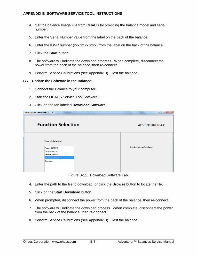
APPENDIX B SOFTWARE SERVICE TOOL INSTRUCTIONS
Ohaus Corporation www.ohaus.com B-8 Adventurer™ Balances Service Manual
4. Get the balance Image File from OHAUS by providing the balance model and serial number.
5. Enter the Serial Number value from the label on the back of the balance.
6. Enter the IDNR number (xxx.xx.xx.xxxx) from the label on the back of the balance.
7. Click the Start button
8. The software will indicate the download progress. When complete, disconnect the power from the back of the balance, then re-connect.
9. Perform Service Calibrations (see Appendix B). Test the balance.
B.7 Update the Software in the Balance:
1. Connect the Balance to your computer.
2. Start the OHAUS Service Tool Software.
3. Click on the tab labeled Download Software.
Figure B-11. Download Software Tab.
4. Enter the path to the file to download, or click the Browse button to locate the file.
5. Click on the Start Download button.
6. When prompted, disconnect the power from the back of the balance, then re-connect.
7. The software will indicate the download process. When complete, disconnect the power from the back of the balance, then re-connect.
8. Perform Service Calibrations (see Appendix B). Test the balance.
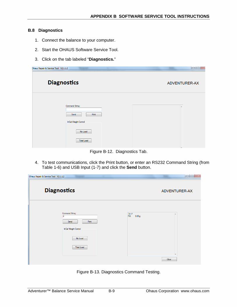
APPENDIX B SOFTWARE SERVICE TOOL INSTRUCTIONS
Adventurer™ Balance Service Manual B-9 Ohaus Corporation www.ohaus.com
B.8 Diagnostics
1. Connect the balance to your computer.
2. Start the OHAUS Software Service Tool.
3. Click on the tab labeled “Diagnostics.”
Figure B-12. Diagnostics Tab.
4. To test communications, click the Print button, or enter an RS232 Command String (from
Table 1-6) and USB Input (1-7) and click the Send button.
Figure B-13. Diagnostics Command Testing.
APPENDIX B SOFTWARE SERVICE TOOL INSTRUCTIONS
Ohaus Corporation www.ohaus.com B-10 Adventurer™ Balances Service Manual
5. The scale’s response will be shown in the box on the right.
B.9 Incal Weight Mechanism Testing
Note: This procedure is used to test that the Incal Weight(s) move(s) smoothly. When the weight(s) is in the lowered position, the display reading should be STABLE. 1. Click on one of the InCal Weight Control buttons: No Load or Total Load.
2. Observe weight displayed on the balance.
A fluctuating display value indicates the weight is not stable. This could be because the weight is not fully lowered and/or because it is touching something. To correct this symptom, follow the procedures in Section 3.6.5. – 3.6.6.


Ohaus Corporation 7 Campus Drive Suite 310 Parsippany, NJ 07054 Tel: (973) 377-9000 With offices worldwide www.ohaus.com
*30122672* P/N 30126672B © 2014 Ohaus Corporation, all rights reserved ™ Registered trademark of Ohaus Corporation. The information contained in this manual is believed to be accurate at the time of publication, but Ohaus Corporation assumes no liability arising from the use or misuse of this material. Reproduction of this material is strictly prohibited. Material in this manual is subject to change.