Embed Size (px)
Citation preview

2/9/2016
1
IMRT and VMAT Patient Specific QA Using 2D and “3D” Detector Arrays
Sotiri Stathakis
Outline
• Why IMRT/VMAT QA
• AAPM TG218 UPDATE • Tolerance Limits and Methodologies for IMRT Verification QA
• Common sources of error
• The ideal dosimeter
• Patient specific QA devices available
• IMRT QA evaluation considerations
• In the era of 3D…
SWAAPM 2013

2/9/2016
2
IMRT/VMAT QA, Why?
• Higher complexity of planning, calculation and delivery compared to 3DCRT
• “…there is evidence that IMRT treatments may not always be as accurate as practitioners believe.” (AAPM TG 119)
• “IMRT doses are calculated by dividing beams into smaller sections, called beamlets, that have varying intensities. Because the dimensions of the beamlets may be too small to establish electronic equilibrium within them, calculations based on corrections to broad-beam data will not suffice.” (Medical Physics, Vol. 30, No. 8, pp. 2089–2115)
SWAAPM 2013
IMRT/VMAT QA, Why?
We need to know if the plan delivered is an accurate
representation (dosimetricaly) of the calculated plan
SWAAPM 2013

2/9/2016
3
The (common) IMRT QA process
• IMRT/VMAT patient plan is approved.
• Plan parameters are copied to a phantom (Verification Plan)
• Plan is recalculated on the phantom geometry.
• Beams can remain as planed for the verification plan (composite verification plan)
• Beams can be arranged to remove gantry, collimator and table angle. (field-by-field verification)
• Calculated dose for a known plane location is exported.
SWAAPM 2013
The (common) IMRT QA process
• The phantom is setup
• Delivery of the plan
• Acquisition of the dose at the specified plane
• Comparison of the calculated and measured planar doses.
• Evaluation/Decision
SWAAPM 2013

2/9/2016
4
The ideal dosimeter should:
• Be accurate
• Be precise
• Show a linear response to dose
• Have minimal variation with radiation quality
• Have minimal variation with absolute dose
• Have minimal variation with dose rate
• Have minimal directional dependence
• Have a high spatial resolution
SWAAPM 2013
Detectors
• Vented parallel plate ionization chambers
• Diodes
• Liquid ionization chambers

2/9/2016
5
Angular dependence
SWAAPM 2013
Shimohigashi et al. JACMP, VOLUME 13, NUMBER5, 2012
• Almost all detector arrays experience angular dependence.
• Solutions
• Use inclinometer and internal angular dependence corrections
• Manufacture phantoms that account for the problem
• Irradiate only perpendicular to the detector
Absolute Dose
• Vented IC
• Can be calibrated and measure absolute dose
• Diodes
• Need cross calibration
• Liquid Filled IC
• Need cross calibration
SWAAPM 2013

2/9/2016
6
Detector size and resolution
• Vented IC
• Large compared to the other two solutions
• Volume averaging
• Diodes
• Smallest
• Liquid filled IC
• Smaller than vented IC
SWAAPM 2013
Energy Dependence
• Diodes experience energy dependence
• Solution
• Use of separate calibration files
• Ionization chambers have minimal energy dependence
SWAAPM 2013

2/9/2016
7
Failed IMRT/VMAT QA
• Device Setup errors/phantom setup errors
• Exported planar dose of the wrong plane or orientation (sagital instead of coronal)
• If TPS does not export using Patient name planar doses can be mixed
• Exclusion of the couch can introduce errors.
• Detector was not warmed up
• Detector was used with a different machine user factor
• Detector was not calibrated correctly
Failed IMRT/VMAT QA
• Wrong calibration curve was used (film/diodes)
• Detector does not have up to date calibration
• Incorrect tolerance criteria
• Connectivity issues
• Dose gradients too steep for detector resolution

2/9/2016
8
Failed IMRT/VMAT QA
• Re-measure
• Re-export
• Re-evaluate
• Re-Setup
• Re-measure
• Re-evaluate
SWAAPM 2013
The devices
SWAAPM 2013
2/9/2016
9
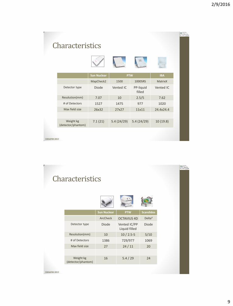
Characteristics
Sun Nuclear PTW IBA
MapCheck2 1500 1000SRS MatrixX
Detector type Diode Vented IC PP-liquid filled
Vented IC
Resolution(mm) 7.07 10 2.5/5 7.62
# of Detectors 1527 1475 977 1020
Max field size 26x32 27x27 11x11 24.4x24.4
Weight kg (detector/phantom)
7.1 (21) 5.4 (24/29) 5.4 (24/29) 10 (19.8)
SWAAPM 2013
Characteristics
Sun Nuclear PTW Scandidos
ArcCheck OCTAVIUS 4D Delta4
Detector type Diode Vented IC/PP Liquid filled
Diode
Resolution(mm) 10 10 / 2.5-5 5/10
# of Detectors 1386 729/977 1069
Max field size 27 24 / 11 20
Weight kg (detector/phantom)
16 5.4 / 29 24
SWAAPM 2013

2/9/2016
10
Software
Verisoft® SNC patient® OmniPro- I’mRT® Delta4®
SWAAPM 2013
Patient specific QA
Arc
Ch
eck
OC
TAV
IUS
4D
De
lta4
Map
Ch
eck
PTW
15
00
OC
TAV
IUS1
00
0SR
S
Mat
riX
X
Field by Field*
Composite (static gantry)
“True” Composite*
VMAT
with a dedicated phantom
SWAAPM 2013

2/9/2016
11
From Approved Plan to Verification Plan
At the TPS…
• TPS calculated verification plan on phantom
• Extraction of planar dose at the level of the detector
• Delivery of the plan to the phantom • Comparison of measurement vs.
calculated planar doses

2/9/2016
12
At the linac…
PTW Octavius II

2/9/2016
13
IBA I’mRT MatriXX
Scandidos Delta4

2/9/2016
14
PTW Octavius 4D Axial (γ=99.4%) Coronal (γ=97.2%) Sagittal (γ=98.6%)
PTW Octavius 1000SRS

2/9/2016
15
PTW Octavius 1000SRS
PTW Octavius 1000SRS

2/9/2016
16
CTRC experience - Point measurements
TomoTherapy Pinnacle Corvus
CTRC experience – overall γ index

2/9/2016
17
CTRC experience - Field by Field analysis
3%/3mm 2%/2mm 3%/3mm 2%/2mm 3%/3mm 2%/2mm
CTRC experience - Composite plan analysis

2/9/2016
18
CTRC experience
CTRC experience – RA Comparison 2D planar dose, 3%-3mm,10% threshold
Patient # SITE FILM IBA MatriXX PTW
Seven29
Scandidos ∆4
1 Brain 91.7 99.8 94.5 98.8
2 Brain 99.3 99.2 98.9 99.8
3 H&N 94.4 98.8 95.8 99
4 Liver 100 100 99.8 99.8
5 Lung 99.6 95.7 98.7 99.2
6 Lung 99.9 97.9 99.9 98.1
7 Prostate 94.9 98.3 96.0 97.2
8 Prostate 98.8 97.9 97.9 98.1
9 Prostate 94.2 96.2 96.8 98.1
10 Prostate 94.0 97.5 96.2 98.4
11 Prostate 98.4 98.4 97.8 96.5
12 Prostate 99.1 95.1 98.4 97.9
13 Prostate 92.9 96.7 99.4 97.4
14 Prostate 99.2 98.9 99.8 98.9
15 Spine 96.8 96.2 98.7 99.3
Average 96.9 97.8 97.9 98.4
SWAAPM 2013

2/9/2016
19
How to pass IMRT QA
Considerations for IMRT QA evaluation
Uncertainties - From AAPM TG218
• “There are many sources of uncertainty in IMRT planning and delivery.”
• In terms of treatment planning, the uncertainties include: • MLC leaf end modeling (MLC systems), • MLC tongue and groove effect, • leaf/collimator transmission, • collimators/MLC penumbra modeling, • compensator systems (scattering, beam hardening, alignment), • output factors for small field sizes, • head backscatter, • dose calculation grid size, • off-axis profiles and • heterogeneity corrections.

2/9/2016
20
Uncertainties - From AAPM TG218
• Spatial and dosimetric uncertainties of the delivery systems also have effects on IMRT dose distribution delivery accuracy.
• These uncertainties include: • MLC leaf position errors (random and
systematic), • MLC leaf speed acceleration/deceleration, • Gantry rotational stability, • Table motion stability, and • Beam stability (flatness, symmetry, output,
dose rate, segments with low MUs).
Uncertainties - From AAPM TG218
• Another source of uncertainty among clinics using measurement-based patient-specific IMRT QA programs are the measurement and analysis tools used to interpret the QA results.
• These software tools have several parameters that must be chosen to perform the analysis and the results can vary significantly depending on those choices.
• One example is the selection of whether to use global or local dose normalization to compare measured and calculated dose distributions.

2/9/2016
21
From AAPM TG218
From AAPM TG218-recommendations
• Global normalization should be used.
• Local normalization is more stringent than global normalization for routine IMRT QA. It can be used during the IMRT commissioning process and for troubleshooting IMRT QA.
• The dose threshold should be selected to exclude low dose areas that have no or little clinical relevance

2/9/2016
22
From AAPM TG218-recommendations
• IMRT QA, tolerance limits, and action limits
• Perpendicular field-by-field (PFF)
• Perpendicular composite (PC)
• True Composite (TC)
• This method most closely simulates the treatment delivery to the patient.
From AAPM TG218-recommendations
• IMRT QA measurements should be performed using the TC delivery method
• IMRT QA measurements should be performed using the PFF delivery method if the QA device is not suitable for TC measurements.
• IMRT QA measurements SHOULD NOT be performed using the PC delivery method which is prone to masking delivery errors.
• Analysis of IMRT QA measurements and the corresponding treatment plan should be performed in absolute dose mode
• A dose calibration measurement compared against a standard dose should be performed before each measurement session to factor the variation of the detector response and accelerator output into the IMRT QA measurement.

2/9/2016
23
From AAPM TG218-recommendations
• Tolerance limits: the γ passing rate should be ≥ 95%, with 3%/2mm and a 10% dose threshold.
• Action limits: the γ passing rate should be ≥ 90%, with 3%/2mm and a 10% dose threshold.
• Tighter criteria should be used, such as 2%/1mm or 1%/1mm to detect subtle regional errors
• A dose threshold below 10% should be considered if the critical structure dose tolerance is less than 10% of the prescription dose (e.g. IMRT re-irradiation cases) or the low dose region is clinically relevant.
From AAPM TG218-recommendations
• For IMRT QA performed with an IC and film, tolerance and action limits for the ion chamber measurement should be within ≤ 2% and ≤ 3%, respectively, and the film γ passing rate limits should be assessed as specified above.
• The IMRT treatment process should be monitored and thoroughly investigated if the γ passing rate is systematically lower than the tolerance limits and higher than the action limits.

2/9/2016
24
From AAPM TG218-recommendations
• For any case with γ passing rate less than 100%,
• the γ distribution should be carefully reviewed rather than relying ONLY on distilled statistical evaluations,
• review of γ results should include other relevant γ values (maximum, mean, minimum, median), as well as a histogram analysis.
• an analysis of the maximum γ value and the percentage of points that exceed a γ value of 1.5 should be performed.
From AAPM TG218-recommendations
• γ statistics should be reviewed on a structure by structure basis if the user software allows for it (vendors should include this feature in their future software development).
• Track γ passing rates across patients (vendors should support a tracking feature in their future software development).
• Whenever referring to a γ passing rate, always specify the dose difference (global or local) and DTA criteria and the dose threshold. Without these parameters, the passing rate is meaningless.
• Software tools that can provide a measure of the agreement between measured and calculated DVHs of patient structures are preferred over analysis in phantoms.

2/9/2016
25
2D γ index 3%, 3mm, Max dose, 10% threshold
SWAAPM 2013
3D γ index 3%, 3mm, Max dose, 10% threshold
SWAAPM 2013

2/9/2016
26
2D γ index 3%, 3mm, Local dose, 10% threshold
SWAAPM 2013
3D γ index 3%, 3mm, Local dose, 10% threshold
SWAAPM 2013

2/9/2016
27
2D γ index 3%, 3mm, Max dose, 0% threshold
SWAAPM 2013
2D γ index 3%, 3mm, Max dose, 0% threshold
SWAAPM 2013

2/9/2016
28
3D γ index 3%, 3mm, Max dose, 0% threshold
SWAAPM 2013
2D γ index 2%, 2mm, Max dose, 10% threshold
SWAAPM 2013

2/9/2016
29
3D γ index 2%, 2mm, Max dose, 10% threshold
SWAAPM 2013
Summary
• Electronic 2D detector arrays suffer from limited spatial resolution and angular dependence
• Provide fast and efficient methods of patient specific QA
• No direct correlation between γ index and plan quality
• 3D dose computation solutions are currently available and provide more information for plan evaluation.
SWAAPM 2013

2/9/2016
30
• Thank you