Embed Size (px)
Citation preview

1
Presented by
John S. Levine, P.E.
Levine Lectronics and Lectric, Inc.
www.L-3.com
Post Glover Resistors, Inc.
Advantages and Disadvantages of
Different Types of Neutral Grounding
Systems

2
OBJECTIVES
1. Discuss five types of grounding for power
systems.
2. Discuss advantages of high resistance grounding.
3. Show equipment
NEUTRAL GROUNDING OF POWER
SYSTEMS

3
POWER SYSTEM GROUNDING
Power system grounding is a connection between an
electrical circuit or equipment and the earth or to some
conducting body that serves in place of earth.
This presentation concerns the design of power system
grounding for industrial and commercial facilities – not
utility systems.

4
DISCUSSION OF GROUNDING
1. Ungrounded system
2. Solidly grounded system
3. Reactive grounded system
4. Low resistance grounded system
5. High resistance grounded system
5
Are You at Risk?NFPA70E
Do you use
electricity?
Electrical deficiencies
are the leading ignition
source and cause of
fire and explosion.

6
What is a Ground Fault?
Contact between ground and an energized conductor
Unleashes large amount of electrical energy
Dangerous toequipment and people

7
POWER SYSTEM GROUNDING
SYSTEM FAILURES – SHORT CIRCUITS
(FAULTS)
INDUSTRIAL POWER SYSTEMS
1. LINE TO GROUND
2. PHASE - PHASE
3. THREE PHASE
FAILURE MODE
PERCENTAGE
OF FAILURES
Most three phase faults are man-made:
I.E. Accidents caused by improper operating procedure.
98 %
<1.5 %
<.5 %

8
Two Types of Faults
Bolted FaultsSolid connection between two phases
or phase and ground resulting in high
fault current.
Stresses are well contained so fault
creates less destruction.
Arc FaultsUsually caused by insulation
breakdown, creating an arc between
two phases or phase to ground.
Intense energy is not well contained,
and can be very destructive.

10
600 Volt “THHN” Power Cable on “Ungrounded” System
Arcing
Fault

11
Arc FaultUsually caused by insulation breakdown, an arc
jumps between two phases or between one phase and a grounded metal surface.
The resulting fault current is smaller because of the relatively high resistance of the arc (25-40% of a bolted fault).
Protective devices may be slow in responding to the smaller fault current.
Arc faults can be the most destructive because of the intense energy that is concentrated in the small area of the arc.
The majority of the stresses (thermal and mechanical) are not confined within the bus-bar and associated supports, it extends to the space in the compartment.

12
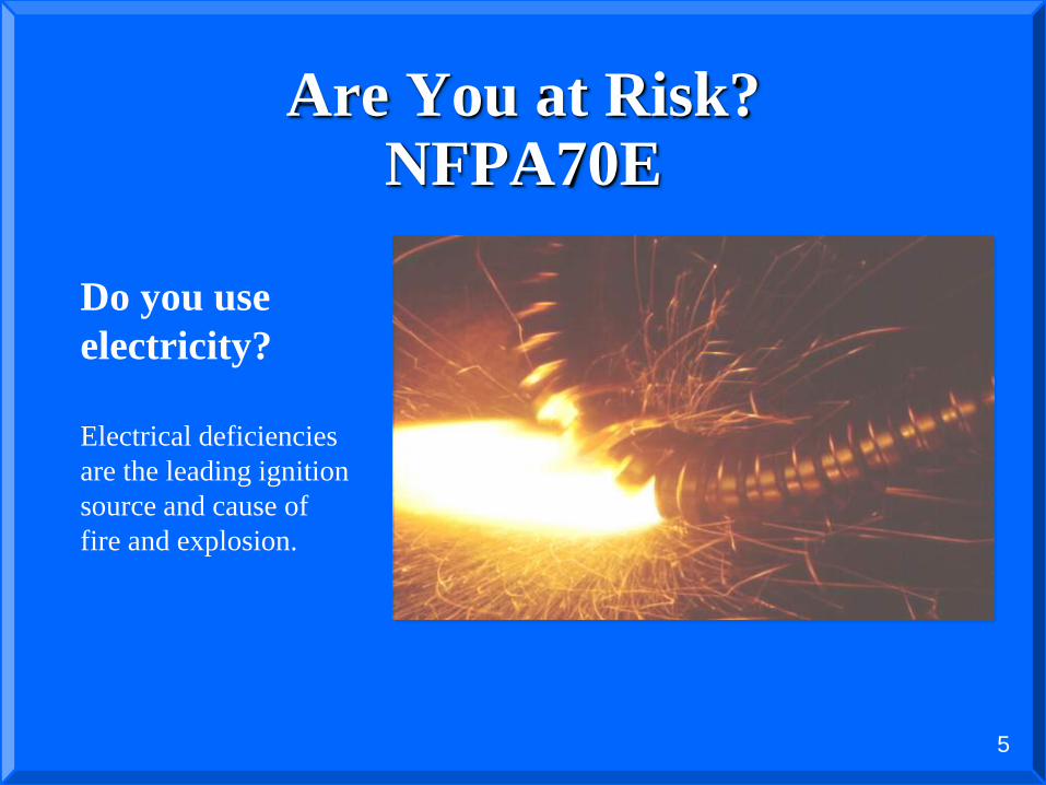
THE ARCING FAULT
An arcing fault is an intermittent failure between
phases or phase to ground. It is a discontinuous
current that alternately strikes, is extinguished and
restrikes again. For solidly grounded systems, the arc
currents are: in percent of bolted three phase faulted
FAULTS
THREE PHASE 89%
LINE-LINE 74%
LINE-GROUND 38%
13

14
Arcing Ground FaultsIntermittent or Re-strike
Intermittent ground fault: A re-striking ground fault can create a high frequency
oscillator (RLC circuit), independent of L and C values, causing high transient over-
voltages.
– i.e. re-striking due to ac voltage waveform or loose wire caused by vibration
V V
480V Delta Source
3Ø Load
Cb bC
Rfe
faS

15
Plot of transient over-voltage for an arcing ground fault
Arcing Ground Faults
Intermittent or Re-strike

16
Industry RecommendationsIEEE Std 242-2001 (Buff Book)
Recommended Practice for Protection and Coordination of Industrial and Commercial
Power Systems
8.2.5 If this ground fault is intermittent or allowed to continue, the system could be
subjected to possible severe over-voltages to ground, which can be as high as six to
eight times phase voltage. Such over-voltages can puncture insulation and result in
additional ground faults. These over-voltages are caused by repetitive charging of the
system capacitance or by resonance between the system capacitance and the inductance
of equipment in the system.
17
THE UNGROUNDED POWER SYSTEM

18
THE UNGROUNDEDED POWER SYSTEM

19
UNGROUNDED SYSTEM
NORMAL CONDITIONS

20
UNGROUNDED SYSTEM
NORMAL CONDITIONS

21
UNGROUNDED SYSTEMGROUND FAULT ON PHASE A

22
UNGROUNDED SYSTEM
GROUND FAULT ON PHASE A

23
THE UNGROUNDED POWER SYSTEM
GROUND DETECTION CIRCUIT

24
THE UNGROUNDED POWER SYSTEM
GROUND DETECTION CIRCUIT

26
THE UNGROUNDED POWER SYSTEM
ADVANTAGES
1. Low value of current flow for line to ground fault-
5 amps or less.
2. No flash hazard to personnel for accidental line to
ground fault.
3. Continued operation on the occurrence of first line to
ground fault.
4. Probability of line to ground arcing fault escalating to
line – line or three phase fault is very small.

27
THE UNGROUNDED POWER SYSTEM
DISADVANTAGES
1. Difficult to locate phase to ground fault.
2. The ungrounded system does not control transient
overvoltages.
3. Cost of system maintenance is higher due to labor of
locating ground faults.
4. A second ground fault on another phase will result in a
phase-phase short circuit.

28
THE SOLIDLY GROUNDED POWER
SYSTEM

29
THE SOLIDLY GROUNDED POWER SYSTEM

30
SOLIDLY GROUNDED SYSTEMTHREE PHASE SHORT CIRCUIT

31
SOLIDLY GROUNDED SYSTEMTHREE PHASE SHORT CIRCUIT

32
SOLIDLY GROUNDED SYSTEM LINE – GROUND SHORT CIRCUIT

33
SOLIDLY GROUNDED SYSTEM
LINE – GROUND SHORT CIRCUIT

34
SOLIDLY GROUNDED SYSTEMLINE-LINE SHORT CIRCUIT

35
THE SOLIDLY GROUNDED POWER SYSTEM
LINE TO GROUND FAULT

36
Industry Recommendations
IEEE Std 141-1993 (Red Book)
Recommended Practice for Electric Power Distribution for Industrial Plants
7.2.4 The solidly grounded system has the highest probability of escalating into a
phase-to-phase or three-phase arcing fault, particularly for the 480V and 600V systems.
The danger of sustained arcing for phase-to-ground fault probability is also high for the
480V and 600V systems, and low for the 208V systems. For this reason ground fault
protection is shall be required for system 1000A or more (NEC 230.95). A safety
hazard exists for solidly grounded systems from the severe flash, arc burning, and
blast hazard from any phase-to-ground fault.

37
THE SOLIDLY GROUNDED
POWER SYSTEM
ADVANTAGES
1. Controls transient over voltage between the neutral and
ground.
2. Not difficult to locate the fault.
3. Can be used to supply line-neutral loads

38
THE SOLIDLY GROUNDED
POWER SYSTEM
DISADVANTAGES
1. Severe flash hazard
2. Main breaker may be required
3. Loss of production
4. Equipment damage
5. High values of fault current
6. Single-phase fault escalation into 3 phase fault is likely
7. Creates problems on the primary system

39
NEUTRAL GROUNDING
RESISTOR

40
NEUTRAL GROUNDING
RESISTOR with Transformer

41
Reactive Grounding
Uses reactor not resistor
Fault values of transient-overvoltages are
unacceptable in industrial environments
Typically found in high voltage applications (>46
kV)

42
LOW RESISTANCE GROUNDING OF
POWER SYSTEMS

43
LOW RESISTANCE GROUNDING OF
POWER SYSTEMS
This design is generally for the following systems:
• At 2.4 kv through 35 kv.
• Systems serving motor loads
• Current is limited to 200 to 400 amps
• Systems typically designed to shut down in 10 seconds

44
LOW RESISTANCE GROUNDED
POWER SYSTEMS

45
LOW RESISTANCE GROUNDED
ZERO SEQUENCE RELAYING PARTIAL SINGLE LINE

46
LOW RESISTANCE GROUNDED
POWER SYSTEMS400 AMP GROUNDING
Disadvantages
• Relatively large ground fault is required and thermal damage and core restacking is possible
• The faulted machine is shutdown
• Starter fuse may also operate
• Must trip upstream circuit breaker.
Advantages
• 400 amp grounding does look at a large part of the machine winding.
• If the Maintenance team is poorly trained, will shut down system in 10 second

47
HIGH RESISTANCE GROUNDING
OF POWER SYSTEMS

48
THE HIGH RESISTANCE
GROUNDED
POWER SYSTEM

49
No Single Phase Loads
No line-to-neutral loads allowed, prevents Hazards.
AØ BØ
CØ
3Ø Load
HRG
480V Wye Source
N
0V
277V
Ground ≈ AØ
Line-to-neutral Voltage is backfed via
neutral wire, thus, not allowed.
0V
480V
480V
277V

50
HIGH RESISTANCE GROUNDING
EXAMPLE
51
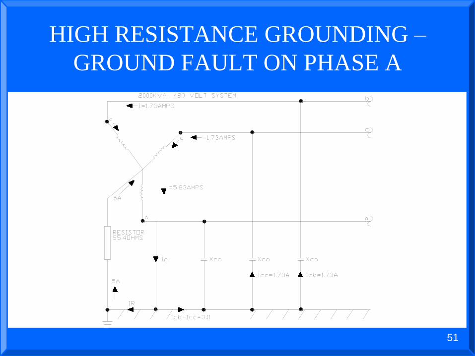
HIGH RESISTANCE GROUNDING –
GROUND FAULT ON PHASE A

52
HIGH RESISTANCE GROUNDING –
GROUND FAULT ON PHASE A

53
HIGH RESISTANCE GROUNDED SYSTEMLINE-GROUND SHORT CIRCUIT

54
THE HIGH RESISTANCE GROUNDED
POWER SYSTEMCONTROL OF TRANSIENT OVERVOLTAGE

55
How Modern High Resistance
Grounding Systems Calculate the
Capacitive Charging Current

57
THE HIGH RESISTANCE GROUNDED
POWER SYSTEMLINE – GROUND FAULTS – DELTA CONNECTED MOTORS

58
THE HIGH RESISTANCE GROUNDED
POWER SYSTEMLINE-GROUND FAULTS WYE CONNECTED MOTORS

59
HIGH RESISTANCE GROUNDING
OF A 2400 / 1385 VOLT SYSTEM

60
THE HIGH RESISTANCE GROUNDED
POWER SYSTEM
CHOOSING THE GROUND RESISTOR
Always specify a continuously rated resistor for 5 amps for all
system voltages.
SYSTEM
VOLTAGE
RESISTOR
AMPS
RESISTOR
OHMS
RESISTOR
WATTS
(CONTINUOUS)
380 5 43.88 1,097
415 5 47.92 1,198
480 5 55.4 1,385
600 5 69.3 1732
2400 5 277 6,925
3300 5 295 7,375
4160 5 480 12,000

61
THE HIGH RESISTANCE GROUNDED
POWER SYSTEM
ADVANTAGES
1. Low value of fault current
2. No flash hazard
3. Controls transient over voltage
4. No equipment damage
5. Service continuity
6. No impact on primary system
7. Easily find Grounds on the system

62
HOW DO YOU FIND
GROUND FAULTS?
Ungrounded
Solidly grounded
Low resistance grounded
High resistance grounded

63
PROCEDURE FOR LOCATING
GROUND FAULT
1. Alarm indicates ground fault.
2. Technician confirms ground
faults by visiting substation.
3. Voltage on meter relay
4. Current through ground resistor.
5. Substation zero sequence feeder
ammeters will indicate specific feeder
to MCC or Power Distribution Panel.
6.Go to specific MCC or PDP, open
wireway and use clamp-on ammeter
around outgoing leads to determine
failed circuit.
7. Evaluate need to replace or fix
component.

64
Ground Fault Location MethodRogowski Coil
NOTE: Tracking a ground fault can only be done on an
energized system. Due to the inherent risk of electrocution
this should only be performed by trained and competent
personnel wearing proper PPE clothing.

65
Fault Location
Method to quickly locate ground faults.
ZSCT
Meter
ZSCT
MeterMeter
ZSCT
0A
55A
50A
50A80A
80A
50A 50A 50A
50A50A55A30A 30A 30A
30A30A30A
MotorMotor
5A
5A0A
5A
HRG
5A
480V Wye Source85A
CØ
BØAØ
55.4
ohms
Meter reading will alternate from
5A to 10A every 2 seconds.
66
Per IEEE…TO HRG OR NOT TO HRG?
IEEE Std 142-1991 (Green Book)Recommended Practice for Grounding of Industrial and Commercial Power Systems
1.4.3 The reasons for limiting the current by resistance grounding may be one or more of the following.
1) To reduce burning and melting effects in faulted electric equipment, such as switchgear, transformers, cables, and rotating machines.
2) To reduce mechanical stresses in circuits and apparatus carrying fault currents.
3) To reduce electric-shock hazards to personnel caused by stray ground-fault currents in the ground return path.

67
Per IEEE…TO HRG OR NOT TO HRG?
IEEE Std 142-1991 (Green Book)Recommended Practice for Grounding of Industrial and Commercial Power Systems
1.4.3 The reasons for limiting the current by resistance grounding may be one or more of the following.
4) To reduce the arc blast or flash hazard to personnel who may have accidentally caused or who happen to be in close proximity to the ground fault.
5) To reduce the momentary line-voltage dip occasioned by the clearing of a ground fault.
6) To secure control of transient over-voltages while at the same time avoiding the shutdown of a faulty circuit on the occurrence of the first ground fault (high resistance grounding).

68
Per IEEE…
TO HRG OR NOT TO HRG?
IEEE Std 141-1993 (Red Book)
Recommended Practice for Electric Power Distribution for Industrial
Plants
7.2.2 There is no arc flash hazard, as there is with solidly
grounded systems, since the fault current is limited to
approximately 5A.
Another benefit of high-resistance grounded systems is
the limitation of ground fault current to prevent damage
to equipment. High values of ground faults on solidly
grounded systems can destroy the magnetic core of rotating
machinery.

69
Per IEEE…
TO HRG OR NOT TO HRG?
IEEE Std 242-2001 (Buff Book)
Recommended Practice for Electric Power Distribution for Industrial
Plants
8.2.5 Once the system is high-resistance grounded, over-
voltages are reduced; and modern, highly sensitive
ground-fault protective equipment can identify the
faulted feeder on the first fault and open one or both
feeders on the second fault before arcing burn down
does serious damage.
70
Design Considerations with
HRG Systems
National Electrical Code (2017)
250.36 High-impedance grounded neutral systems in which a grounding impedance, usually a resistor, limits the ground-fault current to a low value shall be permitted for 3-phase ac systems of 480 volts to 1000 volts where all the following conditions are met:
1. The conditions of maintenance and supervision ensure that only qualified persons service the installation.
2. Ground detectors are installed on the system.
3. Line-to-neutral loads are not served.

71
Duty Ratings for NGR’sIEEE Std 32
Time Rating and Permissible Temperature Rise for Neutral Grounding
Resistors
Time Rating (On Time) Temp Rise (deg C)
Ten Seconds (Short Time) 760oC
One Minute (Short Time) 760oC
Ten Minutes (Short Time) 610oC
Extended Time 610oC
Continuous 385oC
Increased Fault Time Requires Larger Resistor
Duration Must Be Coordinated With Protective Relay Scheme

72
COMPARISON OF THE FOUR
METHODS

73
HIGH RESISTANCE GROUNDING
OF A 2400 VOLT MOTOR SYSTEMCOMPARISON OF SOME CHARACTERISTICS
74
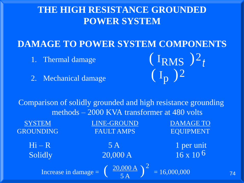
THE HIGH RESISTANCE GROUNDED
POWER SYSTEM
DAMAGE TO POWER SYSTEM COMPONENTS
Comparison of solidly grounded and high resistance grounding
methods – 2000 KVA transformer at 480 volts
1. Thermal damage
2. Mechanical damage
IRMS( )2
Ip( )2
SYSTEM
GROUNDING
LINE-GROUND
FAULT AMPS
DAMAGE TO
EQUIPMENT
Hi – R 5 A 1 per unit
Solidly 20,000 A 16 x 10 6
Increase in damage = = 16,000,00020,000 A
5 A
2( )
t

75
THE HIGH RESISTANCE GROUNDING
OF POWER SYSTEM
1. No shutdowns when a ground fault occurs
2. Quick identification of the problem
3. Safer for personnel & equipment
4. Offers all of advantages of the ungrounded & solidly
grounded systems
5. No known disadvantages
The high resistance grounded power system provides the
following advantages:

76
Should High Resistance
Grounding be used to help
prevent Arc Flash Hazards to
Personnel?

77
Absolutely!! Since 98% of faults
start off as a phase to ground
faults, this will lower the current
that is supplied to the fault.

78
Can I lower the Amps
Interrupting Capacity (AIC)
rating of my switchgear, if I have
a neutral grounding resistor?

79
No. You could still have a phase
to phase fault that could produce
the high current fault levels.

80
Retrofit from Solidly or
Ungrounded Grounded System
to High Resistance Design
Considerations1. Are cables rated line to line or line to neutral. On a
480 Volt system some old systems have installed 300
Volt cable.
2. Are there surge arrestors and MOV’s on the system.
Are they sufficiently rated?
3. Are the Neutrals on the transformers fully insulated?
4. Are there other sources of power on the circuit?
Generators or Tie Breakers
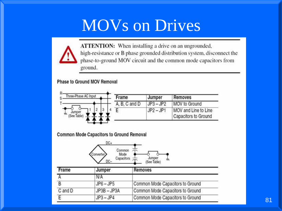
81
MOVs on Drives

82
Resolve NEC requirement
Add small 1:1
transformer and solidly
ground secondary for 1Φ
loads (i.e. lighting).

83
High Resistance Grounding
What if no neutral exists (i.e. delta systems)?
– A grounding transformer is installed (either a zig-zag or a wye-delta)
from all three phases to create an artificial neutral for grounding
purposes only.
HRG
Broken Delta
Grounding
Transformers
Wye-Delta
Grounding
Transformers
HRGHRG
Zig-Zag
Grounding
Transformer
CØBØAØ AØ BØ CØAØ BØ CØ

84
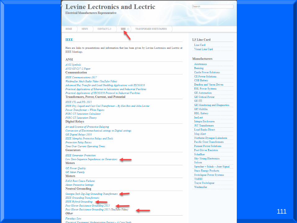
Zig-Zag Wiring
See Georgia Tech Zig-Zag Grounding Transformers paper at L-3.com, IEEE tab

85
Minimum Specifications
120 Volt Control Circuit
385ºC Temperature Rise Resistor
Line Disconnect Switch
Ground Bus (freestanding units only)
Pulser, Including Pulsing Contractor, Pulsing Timer, Normal/Pulse Selector Switch
Unit shall have method to determine Capacitive Charging Current
Relays for under and over voltage
Relays for under and over current measuring only fundamental
Auxiliary contacts
Test Push-button
Fault Reset Push-button
Green Indicating Light for “Normal” Indication
Red Indicating Light for “Fault” Indication

86
CHARGING CURRENT
CALULATIONS
Slides to Calculate are hidden due to
time allowed for Presentation
Some manufactures are now bringing in the 3 phase voltages and determining the capacitive
charging current on the actual system.

93
GENERATOR APPLICATONS
OF NEUTRAL GROUNDING
RESISTORS

94

95
GENERATOR APPLICATONS
OF NEUTRAL GROUNDING
RESISTORS
1. All generators should use a NGR.
2. If you have 2 generators on a system with different pitches you will need to use 2 NGRs to limit the harmonics that are generated.
3. On a delta generator you should use an NGR with a zig-zag transformer.
96
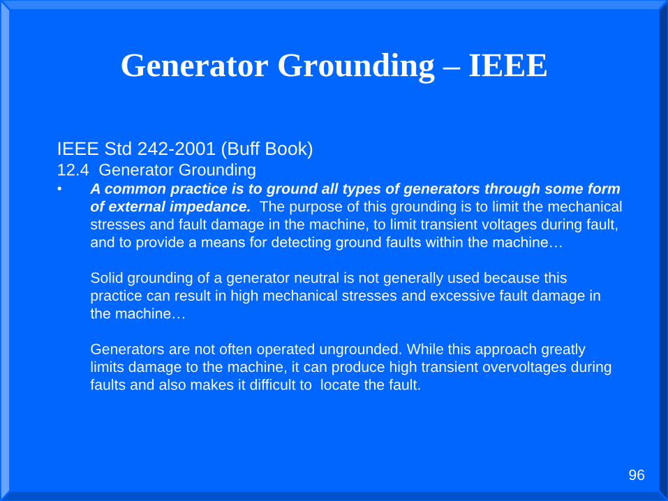
Generator Grounding – IEEE
IEEE Std 242-2001 (Buff Book)12.4 Generator Grounding• A common practice is to ground all types of generators through some form
of external impedance. The purpose of this grounding is to limit the mechanical
stresses and fault damage in the machine, to limit transient voltages during fault,
and to provide a means for detecting ground faults within the machine…
Solid grounding of a generator neutral is not generally used because this
practice can result in high mechanical stresses and excessive fault damage in
the machine…
Generators are not often operated ungrounded. While this approach greatly
limits damage to the machine, it can produce high transient overvoltages during
faults and also makes it difficult to locate the fault.

97
Generator Grounding – IEEEIEEE Std. 142-1991 (Green Book)1.8.1 Discussion of Generator Characteristics• …Unlike the transformer, the three sequence reactances of a generator are not equal.
The zero-sequence reactance has the lowest value, and the positive sequence
reactance varies as a function of time. Thus, a generator will usually have higher
initial ground-fault current than a three-phase fault current if the generator is
solidly grounded. According to NEMA, the generator is required to withstand
only the three-phase current level unless it is otherwise specified…
A generator can develop a significant third-harmonic voltage when loaded. A
solidly grounded neutral and lack of external impedance to third harmonic current will
allow flow of this third-harmonic current, whose value may approach rated current. If
the winding is designed with a two-thirds pitch, this third-harmonic voltage will be
suppressed but zero-sequence impedance will be lowered, increasing the ground-fault
current…
Internal ground faults in solidly grounded generators can produce large fault
currents. These currents can damage the laminated core, adding significantly to the
time and cost of repair…Both magnitude and duration of these currents should be
limited whenever possible.

98
AIC Rating
(Amps Interrupting Current)
This example is taken from lowzero.pdf by Power Systems Engineering (copy on the L-3 web site)
– 3 Phase Short Circuit Calculations for the Generator is 11.1 kA
– Line to Ground Fault Current for the Generator is 13.8 kA because the zero sequence impedance (X0) is lower than the positive sequence impedance (X1)
Line to Ground Fault Current is 125% of the Phase Current Fault in this example
Solution – Make sure you check your AIC rating of the equipment and use a Neutral Grounding Resistor.

99
GENERATOR APPLICATONS
OF NEUTRAL GROUNDING
RESISTORS
A large generator (> 20 MVA, 13,800 volt) may take 5 to 20 seconds to stop. An IEEE working group wrote a series of four papers. They proposed a hybrid system having a low resistance grounding system and when the fault occurred switch to a high resistance grounded system.

100
HYBRID SYSTEM

101
Pictures of Equipment

102
Common options
Enclosure rating
Enclosure finish
Current transformer
Potential transformer
Disconnect switch
Entrance/exit bushings
Elevating stand
Seismic rating
Hazardous area classification
Third party certification

103

104

105
Low Resistance Neutral
Grounding Resistor

106
Low Voltage Pulser

108
Medium Voltage Pulser

109

110
111

112
Thank You
Questions?