Embed Size (px)
Citation preview

Volume XVIMay 2019
Safety Innovations
AdvancingAutomation

Introduction
While automation continues to bring innovation and technologies that can enhance manufacturing efficiency and improve asset productivity, it is also a strong advocate for safety. In particular, worker safety is especially essential in the manufacturing and process industries, where employees are exposed to electrical, chemical or mechanical hazards.
This ebook is dedicated to promoting workplace safety strategies and new technologies. With articles and tips devoted to safety, this ebook has the tools and resources to help ensure an incident-free workplace.

Table of Contents
PAG E 3Advancing Automation eBook Vol. XVI
Performing a Storage Tank Risk Assessmentby: Dean Mallon, Endress+Hauser
Safety Instrumented Systems: The “Logic” of Single Loop Logic Solversby: Moore Industries-International, Inc.
Arc Flash Safety 101: Methods to Help Reduce Exposure to Electrical Hazards by: Glen Kampa, Bob Lau and John Turner, nVent HOFFMAN
10 Things to Consider when Specifying Tank Blanketingby: Bill Carlson, Neutronics, Inc.
Page 4
Page 9
Page 17
Page 25

PAG E 4Advancing Automation eBook Vol. XVI
Performing a Storage Tank
Risk Assessment
API 2350 gives tank owners and operators specific guidance on how to prevent tank overfills. The standard has been around for years, with the fourth edition published in 2012, and the fifth edition expected to be released in mid-2019.
Compliance with these new API practices can also improve normal operation and efficiency. Improved opera-tions are the result of specific, clear and actionable procedures understandable and accessible to operations personnel. Efficiency may improve because implementing API 2350 often results in an expansion of usable tank space.
Primary Points Covered by API 2350
API 2350 contains a series of recommended practices and procedures, including:
• Implement an overfill prevention process
• Apply preventive maintenance practices to overfill prevention system and equipment
• Develop written procedures for operating under normal, abnormal, startup and shutdown conditions—as well as communications between the supply and receiving companies
Are your petroleum storage tanks ready for updates to API 2350? Here’s how to find out and address any issues.
By: Dean Mallon, Level National Product ManagerEndress+Hauser, USA

Figure 1: API 2350 defines a properly instrumented and engineered tank. This tank, for example, has an Independent overfill protection system, a high-high point level switch and an emergency shutdown valve.
Figure 2: Numeric rankings of various factors that can lead to a potential overfill.
PAG E 5Advancing Automation eBook Vol. XVI
• Define initializing operating parameters for each tank. This covers equipment categories, levels of concern, response times and alarm procedures
• Implement and maintain a risk assessment system
Knowing the level of risk is catego-rized as risk assessment, and act-ing to reduce it is referred to as risk management. API 2350 specifically states that a risk assessment must be implemented and maintained, but it does not specify how this should be done.
There are different levels of risk associated with each tank because the filling rates are different, sensors have differing reliability and other fac-tors (Figure 1).
The risk assessment procedures described below are from the newly updated Endress+Hauser Risk Analysis Tool.
Performing a Risk Assessment
The first step is to appoint a team of engineers and operators from the tank farm, or from an outside agency, to perform the risk assessment. This person or team will survey every tank in the plant and assign a risk factor to each one.
The risk factors are arbitrary. Figure 2 shows one potential scenario of numbers, but these can be anything meaningful to the plant.

PAG E 6Advancing Automation eBook Vol. XVI
The ideal tank would be outfitted with instrumentation similar to that shown in Figure 1. The assessment person or team may want to designate this condition as ideal, and then assign risk factors to other tanks with missing instrumentation. Here’s a step by step process for an assessment:
Step 1: A tank group is determined—possibly the oldest group of tanks. Each tank is reviewed for its param- eters, operational procedures, emergency response, operator training and all other relevant factors influencing risk.
Step 2: A sheet is provided to grade or score six areas of concern regarding operations. Each grade is weighted based on the influence or importance of each area.
Step 3: A second sheet pertains to both the likelihood and consequences factors related to an overfill event. The likelihood factors are dependent on tank parameters such as the filling rate, flammability of liquid stored, calibration measures and tank category.
Step 4: Consequence factors are next. They are dependent on corporate values such as preventing flamma- bility, protecting public perception, environmental protection and the severity of an overfill due to tank flow rate.
Step 5: Once each likelihood and consequence factor has been graded by personnel or a tank surveyor, a final score is produced. If the risk score is high, then there is a strong likelihood of a severe risk event. The tanks with the largest risk scores pose the largest threat to a facility and should be addressed first.

ABOUT THE AUTHOR
Dean Mallon has more than 34 years of experience in chemical, petrochemical, refining and terminal automation, holding positions as a company owner to instrumentation sales and currently the Level National Product Manager for Endress+Hauser, USA. Dean has worked with the American Petroleum Institute since 2010. He was part of the working group for the API2350 4th edition on overfill protection and most recently the API2350 5th edition, expected to be published the fall of 2018.
Figure 3: Summary bar chart of risk factors for each tank. The tanks at the left have the highest risk of an overspill.
PAG E 7Advancing Automation eBook Vol. XVI
Step 6: A summary ranking sheet is created from the various risk factors (Figure 3). Once each tank is submitted into the ranking sheet, the result will be a bar graph of the risk score for each tank included in the risk analysis. The tanks with the highest risk scores have the highest bars.
The final outputs of this risk analysis spreadsheet are visual and quantitative representations of the risk associ-ated with each tank.
To request a free copy of Endress+Hauser’s Guidebook, or obtain more information on the risk assessment tool please visit: www.endressdirect.us/api.

Jon Eide Process Consultant for Terminal Management
Gain workflow continuity and streamline processes.
“We take pride in delivering high quality solutions including loading and unloading operations, tank gauging and inventory management systems, as well as overfill prevention.”
Learn more about our terminal management capabilities: go.endress.com/us/terminal-management-capabilities
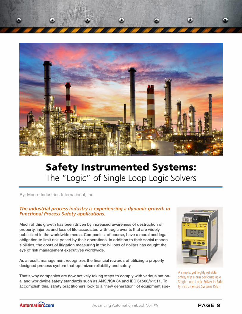
A simple, yet highly reliable, safety trip alarm performs as a Single Loop Logic Solver in Safe-ty Instrumented Systems (SIS).
PAG E 9Advancing Automation eBook Vol. XVI
The industrial process industry is experiencing a dynamic growth in Functional Process Safety applications.
Much of this growth has been driven by increased awareness of destruction of property, injuries and loss of life associated with tragic events that are widely publicized in the worldwide media. Companies, of course, have a moral and legal obligation to limit risk posed by their operations. In addition to their social respon-sibilities, the costs of litigation measuring in the billions of dollars has caught the eye of risk management executives worldwide.
As a result, management recognizes the financial rewards of utilizing a properly designed process system that optimizes reliability and safety.
That’s why companies are now actively taking steps to comply with various nation-al and worldwide safety standards such as ANSI/ISA 84 and IEC 61508/61511. To accomplish this, safety practitioners look to a “new generation” of equipment spe-
Safety Instrumented Systems: The “Logic” of Single Loop Logic Solvers
By: Moore Industries-International, Inc.

Figure 1: In addition to logic solvers, a typical Safety Instrumented System (SIS) is composed of any number or combination of sensors and final control elements.
PAG E 10Advancing Automation eBook Vol. XVI
cifically designed and approved for use in Safety Instrumented Systems that utilize Electrical and/or Electronic and/or Programmable (E/E/PE) technologies.
Safety Instrumented Systems
A Safety Instrumented System (SIS) is defined as an instrumented system used to implement one or more Safety Instrumented Functions (SIF). A SIS is composed of any combination of sensors, logic solvers and final control elements for the purpose of taking a process to a safe state when predetermined conditions are violat-ed (Figure 1).
A SIF is a function to be implemented by a SIS that is intended to achieve or maintain a safe state for the pro-cess with respect to a specific hazardous event.
Examples of SIF applications include:
• Shutdown in a Hazardous Chemical Process Plant
• Open a Valve to Relieve Excess Pressure
• On/Off Control to Prevent Tank Overflow
• Shutdown Fuel Supply to a Furnace
• Add Coolant to Arrest Exothermic Runaway
IEC 61508 Provides Guidelines
To help companies implement a SIS, the International Electrotechnical Commission (IEC) developed IEC 61508, the standard for “Functional Safety of Electrical/Electronic/Programmable Electronic Safety-Related Systems”.
• Automatic Shutdown When Operator Not Present
• Close a Feed Valve to Prevent Tank Overflow
• Initiate Release of a Fire Suppressant
• Initiate an Evacuation Alarm

Table 1: The SIL is a measure of the amount of risk reduction provided by a Safety Instrumented Function, with SIL 4 having the highest level of safety integrity, and SIL 1 the lowest. Table 1 describes safety in three columns—all mathematically related (e.g., RRF = 1/PFD).
PAG E 11Advancing Automation eBook Vol. XVI
The main objective of IEC 61508 is to provide a design standard for Safety Instrumented Systems to reduce risk to a tolerable level by following the overall hardware and software safety life cycle procedures, and by main-taining the associated stringent documentation.
IEC 61508 has become the benchmark used mainly by safety equipment suppliers to show that their equipment is suitable for use in Safety Integrity Level (SIL) rated systems.
For legacy products, suppliers are performing an Failure Modes, Effects and Diagnostic Analysis (FMEDA) hardware only assessment which provides failure data for SIS designers and may also provide proven-in-use data. This does not include any assessment of the product development process which contributes to system-atic faults in the product design.
New products that are fully compliant with IEC 61508 address systematic faults by a full assessment of fault avoidance and fault control measures during hardware and software development.
Safety Integrity Level (SIL)
To determine a SIL, the safety practitioner team RISK/PROCESS HAZARD ANALYSIS (PHA) procedure identifies all process hazards, estimate their risks and decide if that risk is tolerable. Once a SIL has been assigned to a process, the safety practitioner has to verify that the individual components (sensors, logic solvers, final ele-ments, etc.) that are working together to implement the individual Safety Instrumented Functions (SIF) comply with the constraints of the required SIL.
For any device used in a SIS, the team must pay close attention to each device’s Safety Failure Fraction (SFF) and Probability of Failure on Demand (PFDavg). See Tables 1 and 2 for additional information.

Table 2: To be considered for a specific SIL level application, a Type B “Complex” device (such as a microprocessor-based logic solver), must achieve a defined SFF rating. The higher SFF permits higher SIL suitability, plus specifies redundancy levels at each level.
PAG E 12Advancing Automation eBook Vol. XVI
For each device in the SIF, both of these num-bers have to be compared to the rules outlined in the safety standards to ensure that they are sufficient for use in the required SIL of the SIS. If these devices are classified as Type B, such as micro-processor based devices, the devel-opment process including software must also be assessed and approved for the required SIL level. While the standards do allow proven-in-use data as proof of a device’s reliability, such infor-mation is usually very hard to verify and docu-ment. For this reason many end users prefer fully assessed devices by third party organizations.
It is always the responsibility of the end user to perform or verify the calculations for the entire safety loop. Since a SIF relies on more than one device, it is imperative that all devices in the loop work together to meet the required SIL levels. The device’s SFF and the PFDavg values used for these calculations can be found in a FME-DA report.
FMEDA Reports
IEC 61508 requires a quantitative, as well as qualitative, assessment of risk. A Failure Modes, Effects and Diagnostic Analysis (FMEDA) provides a systematic way to assess the effects of all probable and known failure modes, including on-line monitoring and error checking, of a SIS component. It is a detailed circuit and perfor-mance evaluation that estimates failure rates, failure modes and diagnostic capability of a device. This data is provided to be used by a competent functional safety practitioner to determine a device’s applicability in a spe-cific safety-related application. It is best if the FMEDA report is certified by a well-qualified third-party agency that specializes in functional safety approvals.

Time
Input
Alarm StateNon-Alarm State
LIMIT ALARM TRIP
High Alarm
Trip Point
Deadband
High Alarm Trip Resets
Low AlarmTrip Point
Low AlarmTrip Resets
Deadband
Time
Input
ON Trip Point
Relay ONRelay OFF
ON/OFF CONTROLLER
OFF Trip Point
OFF Trip Point
Figure 2: Single Loop Logic Solvers (Safety Trip Alarms), with selectable dead-band to reduce false alarms, can be used to warn of unwanted process conditions or to provide emergency shutdown.
Figure 3: Safety Trip Alarms can be used as simple on/off controllers in level applications (pump/valve control) when filling, emptying or preventing overflow of a container or tank.
PAG E 13Advancing Automation eBook Vol. XVI
“Logical” Logic Solvers
Until recently, the thought of a safety system conjured up images of Triple Modular Redundant (TMR) systems that represent enormous capital expenditures. Today, however, manufacturers offer a wide gamut of safety-cer-tified devices that can be integrated into very cost-effective solutions. One simple, economical, yet highly dependable option is using a Safety Trip Alarm as a Single Loop Logic Solver
A Single Loop Logic Solver (or Safety Trip Alarm), monitors a temperature, pressure, level, flow, position or sta-tus variable. If the input exceeds a selected high or low trip point, one or multiple relay outputs warn of unwant-ed process conditions or provide emergency shutdown (Figure 2), or provide on/off control, such as in a level control application (Figure 3).
Sophisticated Advantages— The sophistication of alarm trips, and their applicability in SIS systems, has increased exponentially since their introduction. This includes programmable inputs; local configuration using on-board controls; safe password protection; a process display; transmitter excitation (the ability to power a transmitter eliminates an additional possible point of failure); and especially, comprehensive internal, input and sensor diagnostics.
Input/Instrument Diagnostics with Fault Alarm— Specially-engineered Safety Trip Alarms can check their own operation and configuration upon start up, and then continuously monitor this information, as well as the input signal. If internally diagnosed faults or external faults, such as loss of sensor or “bad quality input” occur, the alarm will trip a fault alarm.
SIL 2 and SIL 3 Applications— By using the “new generation” of Single Loop Logic Solvers, users realize many of the same advantages of larger and more expensive safety-certified PLCs at a fraction of the cost. If

NC1
CM1
NO1
NC2
CM2
NO2
NC3
CM3
NO3
Final Element
READY INPUT TRIP 1 TRIP 2 FAULT
SELECTDOWNUPCOM
STASAFETYTRIPALARM
TAG
126.39DEG C
ProcessTrip 1
ProcessTrip 2
FaultAlarm
Figure 4: Safety Trip Alarm in a High Integrity Architecture
NC1
CM1
NO1
NC2
CM2
NO2
NC3
CM3
NO3
SELECTDOWNUPCOM
READY INPUT TRIP 1 TRIP 2 FAULT
17.29MA
STASAFETYTRIPALARM
TAG
ProcessTrip 1
ProcessTrip 2
FaultAlarm Logic Solver/
SIF Alarm
Final Element
Figure 5: Safety Trip Alarm in a High Availability Architecture.
PAG E 14Advancing Automation eBook Vol. XVI
a microprocessor based Single Loop Logic Solver has a Safety Failure Fraction greater than or equal to 90%, and the PFDavg data falls within the required range, it is suitable for use in SIL 2 applications using a 1oo1 (no voting or redundancy required) architecture. In a 1oo2 architecture (redundancy) this same Single Loop Logic Solver could be suitable for use in a SIL 3 application provided the software is assessed and suitable for SIL 3 applications.
High Integrity Architecture— This configuration offers the highest trip integrity in a non-redundant applica-tion (Figure 4). Since all three relays are wired in series, any trip alarm or fault alarm will trip the final element or logic solver.
High Availability Architecture— In this configuration, the Safety Trip Alarm provides higher process or system availability (Figure 5). The fault alarm is wired separately to inform a safety system that there is a fault alarm and that this component’s ability to carry out its portion of the Safety Instrumented Function cannot be

NC1
CM1
NO1
NC2
CM2
NO2
NC3
CM3
NO3
READY INPUT TRIP 1 TRIP 2 FAULT
SELECTDOWNUPCOM
STASAFETYTRIPALARM
TAG
123.95DEG C
NC1
CM1
NO1
NC2
CM2
NO2
NC3
CM3
NO3
READY INPUT TRIP 1 TRIP 2 FAULT
SELECTDOWNUPCOM
STASAFETYTRIPALARM
TAG
DEG C
Sensor Input 1
Sensor Input 2
123.95
ProcessTrip 1
ProcessTrip 2
FaultAlarm
ProcessTrip 1
ProcessTrip 2
FaultAlarm
Final Element/Logic Solver
Figure 6: Safety Trip Alarms in a 1oo2 Redundant/Voting Architecture Are Applicable for Use in SIS Systems Up to a SIL 3 Architecture.
PAG E 15Advancing Automation eBook Vol. XVI
performed. This configuration would be used in applications where it is desirable to keep the process running should a fault occur because of a bad input or instrument fault. The output process trip relays are connected in a 1oo2 scheme to trip, providing security against a single relay failure. However, should the fault relay become active, the fault should be removed before the Safety Trip Alarm can provide proper safety coverage.
1oo2 Redundant Architecture— In this architecture, every component appears twice, and may be applica-ble for use in SIS systems up to SIL 3 (Figure 6). Advantages are improved reliability of trip action and reduced vulnerability to a single failure compared to a 1oo1 architecture. The logic in this configuration is an ‘OR’ state-ment for the safety function; if either sensor input reaches a trip condition or a fault relay is activated, the loop or function will reach a tripped state.
ABOUT MOORE INDUSTRIES-INTERNATIONAL, INC.
Moore Industries is a world leader in the design and manu-facture of exceptionally rugged, reliable and high quality field and DIN rail mounted instrumentation for the process moni-toring and control industries. Product lines include Tempera-ture Transmitters and Temperature assemblies and sensors, Functional Safety Instruments; Signal Isolators and Convert-ers; Alarm Trips and Trip Amplifiers; I/P and P/I Converters; Remote I/O and RTUs; HART® Gateways, Monitors and Interfaces; PID Controllers and Backup Stations; Indicators
and Displays; Fieldbus Device Couplers; and more. Our worldwide sales and support offices provide first rate customer service and solutions for the chemical; petrochemical; utilities; petroleum extraction, refining; pulp and paper; food and beverage; mining and metal refining; pharmaceuticals; and biotechnology industries.
PAG E 16Advancing Automation eBook Vol. XVI
Third-Party Safety Certifications
Today, some Single Loop Logic Solvers (Safety Trip Alarms) are designed “from the ground up” in accordance with IEC 61508. An essential requirement to verify their design is a third-party certification from TÜV, Exida or a similarly accredited approval body. This certification provides unbiased, verified evidence that the unit is appro-priate for use in specific SIS strategies. For example, the certification may verify that the device is appropriate for SIFs up to SIL 2 in a simplex or 1oo1 configuration. For increased process availability and/or higher SILs (such as SIL 3), the devices may be applied in 1oo2 or 2oo3 architectures (Figure 6). Hazardous area approvals, specifically Class 1, Division 2 for non-incendive (Type N) applications and Zone 2 applications are a must.
Just the Right Fit
Today, there are solutions for SIS strategies with hundreds of I/O and there are those for systems with just a handful of I/O—and everything in between. The “new generation” in safety-certified Single Loop Logic Solvers fits into this scenario nicely. They provide an extremely affordable option that delivers simple installation, easier validation and faster start-ups. Perpetual benefits that last for the life of the system include less maintenance, faster testing, easier documentation of the safety management reports and modular replacement strategies.

PAG E 17Advancing Automation eBook Vol. XVI
INTRODUCTION TO ELECTRICAL SAFETY
As automation and control systems continue to expand and become increasingly complex, the more crucial it is to take necessary precautions when it comes to electrical safety. Balancing productivity and system optimi-zation with worker safety is a challenging act that requires a disciplined approach. Because of the fatal nature of injuries and cost implications to the business of an electric shock or arc flash incident, the risks are too high to leave things to chance. It takes just one incident to change the life of a worker. The resulting damages are preventable if safety precautions are implemented and followed.
WHAT IS ARC FLASH?
Although not a new phenomenon, awareness of arc flash and protecting against it has become a growing con-cern in the electrical industry. Often, an arc flash event is triggered by operator movement or contact with the energized equipment. This is a particular threat when faults occur within an enclosure. A phase-to-ground or phase-to-phase fault that results in an explosion can cause fatal injuries, severe burns and produce consider-able property damage.
Arc Flash Safety 101: Methods to Help Reduce Exposure to Electrical Hazards
By: Glen Kampa, PE, Bob Lau, PE, and John TurnerAssociates at nVent HOFFMAN

1
5 10to ARC EXPLOSIONSoccur in
electric equipmentin the U.S. EVERY DAY.
2
2000More than
people are treated ANNUALLY in BURN CENTERSwith ARC FLASH INJURIES.
x 200
3
35,000°FElectrical arcs produce some of theHIGHEST TEMPERATURES known to occur on EARTH.
Up to
3.5X hotter than the SURFACE TEMPERATURE OF THE SUN!
4The air expands exponentially by
to the size of a refrigerator
Blast pressure waves have THROWN WORKERS across rooms
67,000times
5Molten METAL AND SHRAPNEL is sprayed at speeds thatexceed
700MPHThis is faster than a JET PLANE.
6The arc blast can have a SOUND MAGNITUDE
Resulting in HEARING LOSS
at a distance of 2 feet from the arc,
Of140dBSource: NFPA 70E - 2015 Edition, Creative Safety Supply (www.creativesafetysupply.com)
PAG E 18Advancing Automation eBook Vol. XVI
STATISTICS ON FATALITIES AND INJURIES DUE TO ARC FLASH
There are 5-10 arc explosions every day in the U.S., resulting in numerous deaths each year. Electrical arcs produce some of the highest temperatures known to occur on earth. Up to 35,000°F, which is 3.5X the surface tempera-ture of the sun. Even when several feet from the arc, fatal burns can occur, as clothing can be ignited from 10 feet away.
When victims do survive, estimates indicate that more than 30,000 non-fatal electrical shock accidents occur each year. According to NFPA 70E, typically, as much as 80 percent of hospital admissions from electrical incidents are a result of burns from an arc flash and ignition of flammable clothing, rather than electrical shock. Over 2,000 people are admitted to burn centers for severe arc flash burns each year.
The pressure from the blast also poses the potential for more injuries. The air expands exponentially as a result of being superheated by the arc current travelling through it. The particles that spray out from the arc, some at speeds that exceed 700 mph, are also superheated and could be a danger to workers.
To add to the list of injuries, the arc blast can have a sound magnitude of 140dB at a distance of 2 feet from the arc, similar to the sound of military jet afterburners. This results in hearing loss.
The numbers of deaths and injuries resulting from arc flash may actually be higher than reported. Burns caused by arc flash may not be classified as an electrical burn or arc flash burn, dwindling the perception of the occurrence of arc flash incidents.
STANDARDS FOR SAFE ELECTRICAL PRACTICE LAWS AND STANDARDS
The National Fire Protection Association (NFPA) 70E Standard for Electrical Safety in the Workplace was written to protect personnel by reducing exposure to major electrical hazards. Originally developed at the request of the Occupational Safety and Health Administration (OSHA), NFPA 70E helps companies and employees avoid workplace injuries and fatalities due to shock, electrocution, arc flash, and arc blast.
The NFPA 70E standard provides the roadmap to comply with OSHA 29 Code of Federal Regulations (CFR), 1910 Subpart S. To protect operators, the standards require an “arc flash boundary” and recommend that electrical work should only take place on de-energized equipment. The “arc flash boundary” is the distance where the incident energy is equal to 5 J/cm2 (1.2 cal/cm2), which is the energy level that unprotected skin will sustain a second degree burn. Access to potentially energized equipment capable of generating an arc flash must be limited to qualified personnel wearing the appropriate Personal Protective Equipment (PPE). Addition-

PAG E 19Advancing Automation eBook Vol. XVI
ally, NFPA 70E describes risk assessments and enclosure labeling. It also covers safety-related work practices, maintenance of electrical equipment/installations, the requirements of special equipment for electrical installa-tion, and employee training.
When safety guidelines are ignored or not enforced and a worker is injured or killed, companies face fines from OSHA. In addition to fines, companies can also face other costs due to destroyed equipment, operation disrup-tions, litigation, higher insurance costs, and worker compensation claims.
WORKPLACE PROCEDURES
The responsibility to ensure a safe workplace environment to protect employees and businesses from harm falls on facility managers, electricians, and control panel engineers. Even the best-designed safety program will not guarantee that it will be consistently implemented and adopted across all workplaces. Implementation of a safety program requires the support of management and the marshalling of many resources. Without this support, safety programs can fail due to urgent priorities, inconsistent training of the workforce and delayed implementation.
Best practices in meeting the OSHA and NFPA 70E safety standard requirements to establish a workplace free of unknown hazards in relation to the electrical system include:
• Risk assessments
• Training programs
• Lockout-tagout procedures
• Marking and identification systems
• PPE
Risk Assessments
Mitigating the risk of electrical hazards begins with shock and arc flash risk assessments. The shock risk as-sessment determines the voltage personnel could be exposed to, shock protection boundary, and appropriate PPE for shock protection. The arc-flash risk assessment determines if an arc-flash hazard exists. If so, it further determines the appropriate safety related work practices, arc-flash boundary, and appropriate PPE for arc-flash protection. The arc flash boundary is relevant to systems 50 volts and greater.
Risk assessments must be updated when a significant modification or renovation involving the electrical distri-bution system occurs or it must be reviewed at least every five years.
Training Programs
Training is critical for all workers who are exposed to electrical hazards. These workers must thoroughly un-derstand the requirements of the electrical safety program, which is required by NFPA 70E and OSHA 29 CFR 1910.147 for all industrial locations and must include safety principles, controls used to measure and monitor, and specific procedures regarding how to work within the safety boundaries.

PAG E 2 0Advancing Automation eBook Vol. XVI
NFPA 70 requires training for two types of groups: Qualified and Unqualified employees. A qualified person has demonstrated skills and knowledge relating to the construction and operation of electrical equipment and installations. This person is typically the electrician who is working on energized conductors. Unqualified per-sonnel are neither trained nor familiar with determining exposed energized conductors or determining nominal system voltage and the apparent hazard.
Qualified employee training includes the identification of specific electrical hazards and the potential risk for injury. It also discusses emergency procedures needed in the event of an incident and first aid care.Unqualified employee training only includes training on electrical safety practices necessary to avoid injury. Retraining or additional training is required when new technology is installed, job roles change, or every three years. It is important that the employer documents employee training.
Lockout/Tagout
Lockout/Tagout (LOTO) procedures are established to protect employees from accidental start-up of equip-ment or accidental release of hazardous energy.
NFPA 70E specifies that LOTO procedures be implemented as part of establishing an electrically safe working condition — see related specification OSHA 29 CFR 1910.147, The Control of Hazardous Energy. Annex G of NFPA 70E Handbook has a sample LOTO program that may be used as a template. A key principle of the LOTO procedure is that a circuit or panel is considered to be “live” until a test instrument is used by a qualified em-ployee wearing required PPE to verify the source(s) of energy are removed. Test instruments are to be verified that they are working properly by checking with a reference voltage source before and after an absence of volt-age test is performed. Wherever possible, verification includes visual inspection of the blades of disconnecting devices to insure they are in the fully disconnected position.
Marking and Labeling
Signage, labeling and identification systems form the backbone for safety information. Safety identification sys-tems can include:
• Signs and labels that indicate hazardous conditions
• Voltage markers, pipe markers, tapes and letters/numbers
• Custom markers
Labeling equipment plays a critical role to alert peo-ple of possible harm. NFPA 70 requires the labeling of switchboards, panel boards, industrial control panels, meter socket enclosures and motor control centers to warn about the potential for arc flash. All power sources for machines are potential sources of danger and are required to be appropriately labeled with information to perform shock and arc flash hazard risk assessments. Figure 1 is an example of an arc flash warning label.

PAG E 21Advancing Automation eBook Vol. XVI
Personal Protective Equipment (PPE)
The purpose of PPE is to reduce employee exposure to hazards when engineering and administrative controls are not feasible or effective to reduce the risks to acceptable levels.
PPE includes specialized clothing or equipment worn by employees to protect the body including the head, face, eyes, ears and hands. The level of PPE is determined by the degree of the shock and arc flash hazard. The arc flash PPE category is determined by the NFPA 70E tables 130.7(C)(15) and 130.7(C)(16) or the Incident Energy Analysis Method is used to decide the required PPE for the task.
The PPE is listed in Table 130.7(C)(16) and is arranged into Categories 1 through 4. Forty cal/cm2 is considered the upper boundary for the maximum anticipated exposure level. Above that, PPE is not able to sufficiently protect employees, which means energized work is prohibited. NFPA 70E Table 130.7(C)(14) lists the standards relevant to protective equipment.
BEST PRACTICES FOR REDUCING RISKS
While PPE is essential to the workplace in protecting against injury from arc flash, it does not eliminate the like-lihood of an incident occurring. To reduce the likelihood of an arc flash event from happening in the first place, modifying the design and configuration of electrical equipment is essential.
DESIGNS THAT KEEP WORKERS SAFE FROM POWERED ELECTRICAL ENCLOSURE
The design and configuration of electrical equipment can be constructed in such a way as to create physical obstructions intended to prevent contact with equipment or live electrical components. Examples of designs and configurations that can help achieve that include:
• Interlock mechanisms— When the power source is on, this mechanism prevents personnel from opening the enclosure. These mechanisms, which can be either mechanical or electrical, assure that power is physically turned off to allow the enclosure door to open. Once the enclosure door is closed, power can then be restored.
The label must include:
1. Nominal system voltage 2. Arc flash boundary
3. At least one of the following
a. Available incident energy and the corresponding working distance OR the arc flash PPE category, but not both
b. Minimum arc rating of clothing
c. Site-specific level of PPE

PAG E 2 2Advancing Automation eBook Vol. XVI
• External disconnect enclosures— An external disconnect enclosure attaches to the side of the control enclosure and houses only the disconnect switch or circuit breaker, physically removing it from the control enclosure. Power passes to the control enclosure via a terminal block mounted on the shared enclosure walls. When the disconnect is off, the line side of the switch, which is still hot, is isolated in the external dis- connect enclosure and there is no power coming into the control enclosure. Work can be done on the control enclosure without exposure to those live parts.
• Internal disconnect shield/enclosures— When the disconnect switch or circuit breaker cannot be moved externally, this provides another alternative to covering the switch when the control enclosure needs to be accessed. The shield on back panel of the control enclosure, enclosing the disconnect and preventing inci- dental contact with the live line side of the switch.
• Infrared (IR) windows— Windows can be installed on the enclosure to provide a view or inspect internal equipment. IR windows in particular allow technicians or thermographers to conduct maintenance tasks or thermal surveys without the need to open the enclosure or de-energize the equipment.
• Data ports— These are used to allow programming access as well as conduct diagnostics to devices inside an enclosure without opening the enclosure. These ports can be mounted on the outside of the enclosure door or wall, allowing personnel to program the device inside the enclosure.
• External data pockets— A data pocket that mounts on the outside of the enclosure to keep manuals and various worksheets outside the enclosure. It keeps these materials nearby for convenience and prevents the need to open the enclosure to access them.
• Lockouts— These are used when more than one person is servicing an enclosure and needs to secure the power source. Safety lockouts ensure that before any work on a machine or equipment is started, all appli cable energy sources have been rendered safe. Personnel can apply individual padlocks to secure the power source when servicing the enclosure and remove their own lock once completed. This ensures that the power source cannot be turned on by one person when another person is servicing the enclosure. The last person to complete the project removes the lock and restores the equipment to operation.

PAG E 2 3Advancing Automation eBook Vol. XVI
BENEFITS OF DESIGNING TO MITIGATE ARC FLASH INCIDENTS
The major benefit of designing to mitigate arc flash incidents is that it is a more effective approach to increase worker safety.
Looking at the main causes of arc flash incidents can help explain why designing for safety is more effective.
• Human error— naive or arrogant attitude on work procedures, amateur maintenance mistakes, and mishandling tools, wires, and metal covers
• Negligent preventive maintenance— not checking for loose terminals, allowing dust and debris build-up (critical in medium and high voltages), and not testing stored energy (e.g., spring-operated bolted pressure switches)
• Inadequate electrical equipment/system design— incorrect configurations or using legacy equipment that doesn’t take hazards into account
Unfortunately, human error is hard to eliminate and negligent preventative maintenance can only be improved to the extent that companies enforce safety programs. However, designing or configuring equipment and sys-tems to reduce the risk of arc flash incidents is very possible, if not a more reliable way to achieve that.
Maintenance is a key factor that should be considered in the system design phase. In high volume production facilities in particular, downtime is an expensive endeavor. Designing a system to avoid downtime includes inte-grating methods of operational verification. For example, infrared thermography is a widely common routine in the electrical maintenance procedures. “Hot spots” caused by defective electrical equipment can give an early indication of looming failure which can be easily identified utilizing infrared camera technology. The detection of these “hot spots” is dependent on the heat generated by the equipment when running or shortly thereafter, either exposing a worker to energized equipment or pressuring the worker into a rushed lockout-tagout pro-cedure to gain accurate data. Both of these scenarios increase the chance of an arc flash incident. Infrared windows, for these reasons, help reduce the likelihood of an arc flash incident and also reduce the time in per-forming routine inspections by eliminating the need for PPE and removal of enclosure covers.
Often, work must be done on an open enclosure. In these instances, external disconnect enclosures effectively mitigates arc flash incidents in two ways. One is through its interlocking mechanism which ensures that the control enclosure door cannot be opened when the disconnect is in the on position. This protects workers from exposure to energized components and complies with interlocking requirements of UL 508A, NFPA 79, IEC 60204 and HS 1738 – the most common electrical standards for industrial machinery. The human error of open-ing the control enclosure before turning the power off or forgetting to close the doors before turning power on is eliminated.
The second reason this system design is effective in mitigating arc flash incidents is because it moves the disconnect switch to an external enclosure. The line side of the switch is live even after the power has been turned off, which is an area with a potential for an arc flash. By physically isolating the risk area to an external location, technicians are able to work on the control enclosure without exposing themselves to live electrical components. As a result, this enables technicians to remove PPE, once a panel is verified power free, while working in the control enclosure.

ABOUT THE AUTHORS
Glen Kampa, PE, Senior Regulatory Engineer and Lab Manager at nVent HOFFMAN. Glen has a Bachelor of Mechanical Engineering degree from the University of Minne-sota and has nearly 30 years of experience with industrial control panel systems. As an active committee member of standard technical panels including UL 508, 508A, 50, and 50E, he holds a wealth of knowledge regarding certifications and standards related to industrial control panel systems.
Bob Lau, PE, Engineering Project Leader at nVent HOFFMAN. Bob has a Bache-lor of Mechanical Engineering degree from the University of Minnesota as well as a Masters of Engineering Management degree from the University of Evansville. In his nearly 30 years at HOFFMAN, Bob has led several innovative new product develop-ment projects. He is involved in the industry as chairman of NEMA 250 and member of IEEE 1584 and IEEE 1814, helping to stay in the forefront of new research and discussions related to standards in electrical safety.
John Turner, Global Product Manager at nVent HOFFMAN. John has a Bachelor of Mechanical Engineering degree from the University of Minnesota. As a product man-ager with an interest in electrical safety, John has sought to expand his understand-ing in the electrical safety landscape to help develop enclosure solutions that not only protect the valuable equipment inside, but also help reduce the risk to people who use the enclosure.
PAG E 2 4Advancing Automation eBook Vol. XVI
Although developing electrical equipment and system designs that eliminate hazards and reduce risks pres-ent an added initial cost upfront, it can be worthwhile investment when fully understanding the implications of not implementing this technology. If a single serious arc flash incident occurs, aside from the physical and emotional damage to the employee, it could cost and employer over $1,000,000 in fines, workers compensa-tion claims, legal fees and equipment downtime. Arc flash is preventable if all safety avenues are considered as a whole.

PAG E 2 5Advancing Automation eBook Vol. XVI
At Neutronics, we work closely with engineers, industrial technicians and process managers - helping them find the right tank blanketing and inerting control solutions for their particular needs across a wide range of indus-tries. If you are looking to specify blanketing or inerting in your process, then this is the right document for you. We’ve created it so we can take out some of the gotchas and head scratching regarding your decision making- sharing our industry expertise with the view to making life a little easier for you.
This guide is laid out in ten simple sections which will help you develop a working specification. This specifica-tion can then be used to help you focus on improving quality, safety, process efficiency and reduce your future costs and maintenance requirements.
10 Things to Consider when Specifying Tank Blanketing
By: Bill Carlson, Technical Services Director for the Gas Analysis division, Neutronics, Inc.
The benefits of tank blanketing include improved process safety, better product quality and longer equipment life. If you are looking to specify a tank blanketing solution for your application, here are ten things you need to consider.

PAG E 2 6Advancing Automation eBook Vol. XVI
01: Process application and descriptionA clear process application and description for your tank blanketing solution helps define the requirements. It should focus specifically on the scope of your project and also your risk management objective.
What’s your project scope?
Applications for tank blanketing and inerting control systems can be found in many of the steps of the man-ufacturing process, ranging from production and product storage to packaging and transportation. This is a widely used practice with applications in a variety of industries such as:
• Chemicals • Pharmaceuticals / nutraceuticals • Paints and coatings • Adhesives / sealants / composites • Personal care • Electronics / semiconductor • Food & beverage
Many of inerting applications involve process vessels, reactors, mixers, centrifuges, grinding mills, blenders, hoppers, separators, exhaust headers, and storage tanks. With a thorough understanding of your manufac-turing process, you will be able to make sure that your inerting control system meets all performance standards and minimizes your gas volume requirements.
The main benefits of using nitrogen or other gases to create inert gas atmospheres include improved safety in the workplace, better quality control, and higher manu-facturing efficiency. On top of that, tank blanketing and inerting control can help you deliver higher value prod-ucts, reduce operating costs, and minimize waste.
What are your key objectives?
Using tank blanketing in your process can be based on a number of different key objectives. It’s useful to take a moment to clarify which objectives are appropriate for your project:
• Eliminating the possibility of fire and preventing explosive atmospheres when handling and processing flammable or combustible materials • Ensuring plant and personnel safety during process start-up and shutdown • Preventing degradation of products that are affected by exposure to oxygen and moisture • Maintaining process quality standards by protecting against exposure to high relative humidity and oxygen levels • Reducing plant operating costs related to inert gas usage

PAG E 27Advancing Automation eBook Vol. XVI
Is your objective to improve process safety?
The National Fire Protection Association Standard on Explosion Protection Systems (NFPA 69) covers the mini-mum requirements for installing systems for the prevention of explosions in enclosures that contain concentra-tions of flammable gases, vapors, mists, dusts, or hybrid mixtures.
Within the standards, oxidant concentration reduction is recognized as a method based on preventing combus-tion. Chapter 7 of these standards, ‘Deflagration Prevention by Oxidant Concentration Reduction’, states that this technique is permitted where an oxidant and flammable material is confined to an enclosure within which the oxidant concentration can be controlled.
For further information on this risk management objective, see section 2 of this document “What O2 measure-ment range do you need?“.
Is your objective to improve quality control?
Many materials and products, especially in the food, pharmaceutical, nutraceutical, and plastics industries, are affected by exposure to oxygen and moisture.
This exposure can degrade the product, causing a reduction in its stability and altering color, flavor, and aroma. Using nitrogen to blanket vessels or shipping containers provides control of the level of oxygen in the vapor space. It can also create a slight positive pressure, preventing air from entering and causing degradation and spoilage.
In the production of high-value plastic products, various flaws frequently result from similar exposure of the material to moisture and oxygen. Inerting process equipment with nitrogen has been proven to reduce relative humidity and oxygen levels, resulting in a reduction of surface defects in molded plastics products.
Is your objective to improve production efficiency and reduce inert gas consumption?
Developing effective strategies to optimize nitrogen usage and to reduce hazardous air pollutants are high pri-ority challenges that need to be considered during safety reviews, plant upgrades, and project planning.
By utilizing continuous real-time oxygen monitoring, the inerting control system adds nitrogen or inert gas only when needed to keep oxygen at a safe level. This can dramatically reduce inert gas usage spending when compared with continuous purge, time-volume, and pressurization techniques.
QUESTIONS:
• How many sample streams do you need to monitor?
• What feed materials are used in the process?
• Are any materials flammable or combustible?
• What are your risk management objectives?

If... Then...
You are using flammable orcombustible materials andyou must improve workplacesafety
Follow the NFPA 69 standard and use continuous O2 monitoring andinerting control to maintain the system at a oxidant concentration that islow enough to prevent combustion
Use continuous O2 monitoring and inerting control to control the level ofoxygen in the vapor space to prevent product degradation
Use continuous O2 monitoring and inerting control to add nitrogen orinert gas only as needed to reduce inert gas consumption
Your product is affected byexposure to oxygen andmoisture and you mustimprove quality control
Your inert gas usage is toohigh and you must improveproduction efficiency
PAG E 2 8Advancing Automation eBook Vol. XVI
02: What O2 measurement range do you need?
Depending on your application process, you will need to decide what oxygen level you want to maintain. If your objective is to improve process safety, what is your target Limiting Oxidant Concentration (LOC) value?
As previously mentioned, the LOC is the concentration of oxidant in a fuel-oxidant-diluent mixture below which a deflagration cannot occur under specified conditions. The NFPA 69 standard includes examples of LOC values for flammable gases and combustible dusts. Paragraph 7.7.2.5 in NFPA 69 requires one of the following: (1) a safety margin of at least 2 volume percent below the worst credible case LOC shall be maintained; (2) the LOC shall be less than 5 percent, in which case the equipment shall be operated at no more than 60 percent of the LOC.
NFPA 69 includes reference tables with LOC values for common flam-mable gases and combustible dusts: https://www.nfpa.org/assets/files/AboutTheCodes/69/TIA_69_14_1.pdf
Blanketing the head-space above the product level in a tank or vessel will go a long way to preventing a reduction in the stability of a product that is affected by exposure to oxygen and moisture. Such exposure can degrade the product, allow unwanted polymerization reactions, or cause surface defects in molded products. By knowing how much O2
is present and by having control of the flow of inert gas to the process, you can greatly improve the quality of your product and maintain tight control of your manufacturing process.
QUESTION:
• If your objective is to prevent product degradation and improve quality control, what is your target maximum oxygen level based on controlling exposure to oxygen and moisture?

PAG E 2 9Advancing Automation eBook Vol. XVI
03: Vessel requirements
Depending on your process application, the type of vessel requirements can vary considerably.
Tank blanketing and inerting control systems are com-monly used in sealed or fixed roof tanks and vessels where the pressure is contained and also in unsealed vessels where the enclosed spaces do not hold pres-sure. Enclosures such as pneumatic conveyors, hoppers that contain powders and dust, or controlled-atmo-sphere containers are best suited for inert gas concen-tration control. With concentration control, the oxygen analyzer directly measures the oxygen concentration in the vapor head-space and uses it to control the flow of nitrogen to the tank.
The advantage of continuous concentration monitoring and control is that it conserves nitrogen by optimizing the inert gas usage. The inerting system measures the oxygen level in real-time and automatically adds inert gas as needed. When the oxygen concentration level drops to the low-level set-point, the nitrogen control valve is deactivated, stopping the flow of inert gas. Compared to a continuous purge, this translates into a reduction in inert gas usage and a subsequent cost savings, providing an accelerated payback on the cost of the monitoring and control equipment.
QUESTION:
• What process equipment details do you need to consider?
• Vessel or enclosure type: pressure vessel, reactor, mixer, centrifuge, grinding mill, blender, hopper, separator, exhaust header, storage tank, tote tank, exhaust header
• Stationary or portable: permanent installation with fixed piping connections or portable vessel requiring flexible connections
• Use: processing, mixing, heating, charging, drying, filtering, storing, etc.
• Materials of construction: carbon steel, stainless steel, Hastelloy, glass or epoxy-lined Volume: overall volume, minimum fill level, maximum fill level
• Vessel dimensions: diameter, length, width, height
• Location: indoors or outdoors
• Area rating: hazardous area (Class I, Div.1 or Div. 2, Class II, Div. 1 or Div. 2) or non-hazardous area

PAG E 3 0Advancing Automation eBook Vol. XVI
04: Operating pressure
Your tank blanketing system should be a complete solution, designed for sampling, sensing, analyzing and controlling oxygen, whatever the operating pressure.
Extractive sampling systems are available in a number of configurations suitable for a variety of different process operating pressures. For operating pressures above 5 PSIG, a pressure regulator should be included in the sample package. For pressures close to atmospheric pressure, an intrinsically safe aspirator should be used to draw the sample from the process. For vapor collection headers and higher vacuum conditions, a vac-uum pump should be included.
QUESTION:
• What are your process operating pressures? Normal, Minimum and Maximum.
05: Operating temperature
A key aspect of reliable oxygen monitoring is making sure that the sample gas temperatures are with-in the design limits of the sensor.
Preconditioning components such as pre-filters, demisters, heat exchangers, and scrubbers are typically used to remove contaminants and reduce sample gas temperatures as needed.
QUESTION:
• What are your process operating temperatures? Normal, Minimum and Maximum
PAG E 31Advancing Automation eBook Vol. XVI
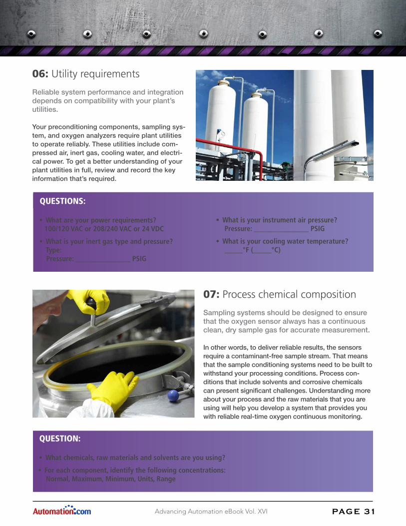
06: Utility requirements
Reliable system performance and integration depends on compatibility with your plant’s utilities.
Your preconditioning components, sampling sys-tem, and oxygen analyzers require plant utilities to operate reliably. These utilities include com-pressed air, inert gas, cooling water, and electri-cal power. To get a better understanding of your plant utilities in full, review and record the key information that’s required.
• What is your instrument air pressure? Pressure: _______________ PSIG
• What is your cooling water temperature? _____°F (_____°C)
QUESTIONS:
• What are your power requirements? 100/120 VAC or 208/240 VAC or 24 VDC
• What is your inert gas type and pressure? Type: Pressure: _______________ PSIG
07: Process chemical composition
Sampling systems should be designed to ensure that the oxygen sensor always has a continuous clean, dry sample gas for accurate measurement.
In other words, to deliver reliable results, the sensors require a contaminant-free sample stream. That means that the sample conditioning systems need to be built to withstand your processing conditions. Process con-ditions that include solvents and corrosive chemicals can present significant challenges. Understanding more about your process and the raw materials that you are using will help you develop a system that provides you with reliable real-time oxygen continuous monitoring.
QUESTION:
• What chemicals, raw materials and solvents are you using?
• For each component, identify the following concentrations: Normal, Maximum, Minimum, Units, Range
PAG E 3 2Advancing Automation eBook Vol. XVI
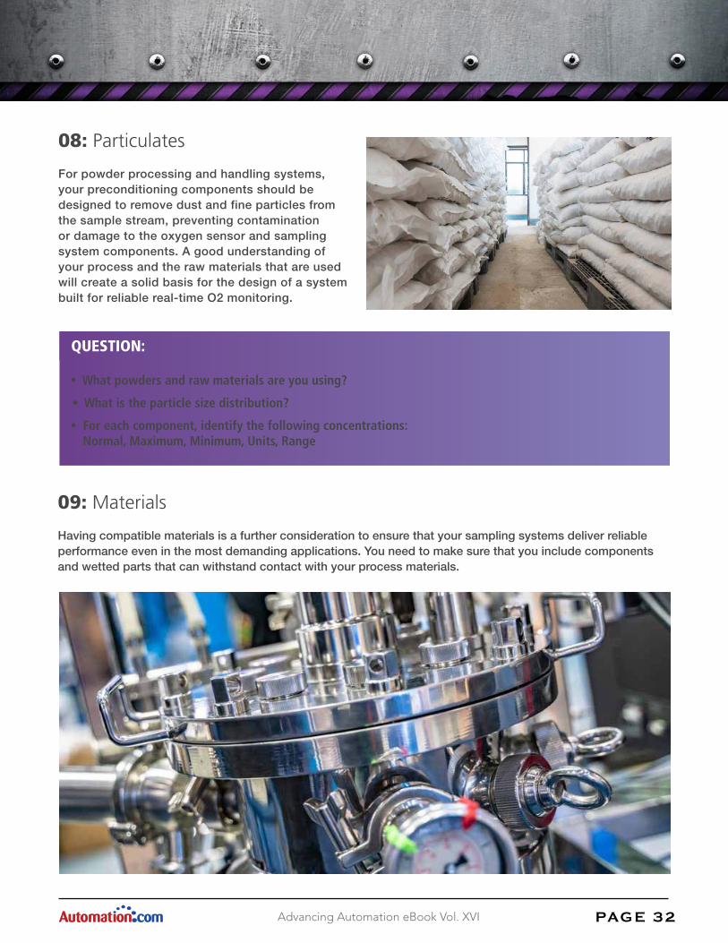
08: Particulates
For powder processing and handling systems, your preconditioning components should be designed to remove dust and fine particles from the sample stream, preventing contamination or damage to the oxygen sensor and sampling system components. A good understanding of your process and the raw materials that are used will create a solid basis for the design of a system built for reliable real-time O2 monitoring.
QUESTION:
• What powders and raw materials are you using?
• What is the particle size distribution?
• For each component, identify the following concentrations: Normal, Maximum, Minimum, Units, Range
09: Materials
Having compatible materials is a further consideration to ensure that your sampling systems deliver reliable performance even in the most demanding applications. You need to make sure that you include components and wetted parts that can withstand contact with your process materials.

PAG E 3 3Advancing Automation eBook Vol. XVI
For some process applications, your material compatibility is dictated by the materials that you are processing. Your previous experience and plant standards can also play a crucial role in this decision. Other variables such as plant operating conditions, ease of maintenance, and cleaning requirements are also important consider-ations to keep in mind.
QUESTION:
• What materials of construction are compatible with your process? Stainless steel, Teflon, Viton, Kynar, Kalrez, Glass, Hastelloy etc.
10: Process sketch or layout
A simple diagram or quick sketch of the process can really support the development of your system.
We’ve found that a simple system sketch is a valuable tool that you can use to collaborate and develop a com-prehensive solution for your application.

ABOUT THE AUTHOR
Bill Carlson is the technical services director for the Gas Analysis division of Neutronics Inc. (456 Creamery Way, Exton, PA 19341; 610-524-8800 x147; [email protected]). He has dedicated the majority of his 29 year tenure to the design and development of oxygen-based inert gas control systems for the chemical, pharmaceu-tical, paints and coatings, adhesives, and personal care industries.
PAG E 3 4Advancing Automation eBook Vol. XVI
Your tank blanketing specialists
We hope you’ve found this document useful for highlighting some of the considerations when speci-fying a tank blanketing solution.
If you would like any help or support in your tank blanketing process application, then please do not hesitate to get in touch and take advantage of our considerable knowledge and expertise.
To download your own free copy of the guide “10 Things to Consider When Specifying Tank Blanketing” then follow this link: https://neutronicsinc.com/resources/10-things-to-consider-when-specifying-tank-blanketing/