Embed Size (px)
Citation preview

CHAPTER 23
ADVANCES IN UNDERWATER ACOUSTIC
NETWORKING
Tommaso Melodia, Hovannes Kulhandjian, Li-Chung Kuo, and
Emrecan Demirors
State University of New York at Buffalo
The field of underwater acoustic networking is growing rapidly thanks to the key role itplays in many military and commercial applications. Among these are disaster preven-tion, tactical surveillance, offshore exploration, pollution monitoring and oceanographicdata collection. The underwater acoustic propagation channel presents formidable chal-lenges, including slow propagation of acoustic waves, limited bandwidth, high and vari-able propagation delay. Furthermore, it is affected by fading, Doppler spread and multipathpropagation. Therefore, efficient protocol design tailored for underwater acoustic sensornetworks entails many challenges across different layers of the networking protocol stack.The objective of this chapter is to provide an overview of therecent advances in underwateracoustic communication and networking. We briefly describethe typical communicationarchitecture of an underwater network followed by a discussion on the basics of underwa-ter acoustic propagation and the state of the art in acousticcommunication techniques atthe physical layer. We then present an overview of the recentadvances in protocol designat the medium access control and network layers as well as in cross-layer design. Finally,we provide a detailed discussion of the existing underwateracoustic platforms for experi-mental evaluation of underwater acoustic networks.
804Mobile Ad Hoc Networking: Cutting Edge Directions, Second Edition. Edited by Stefano Basagni,Marco Conti, Silvia Giordano and Ivan Stojmenovicc© 2013 by The Institute of Electrical and Electronics Engineers. Published 2013 by John Wiley & Sons, Inc.
INTRODUCTION 805
23.1 INTRODUCTION
It has been argued that the recent disastrous spill that followed the oil-rig explo-sion in the Gulf of Mexico in the Summer of 2010 could have beenprevented byacoustic sensing/actuating systems (recently mandated for example by Norway andBrazil) that can be triggered by acoustic control signals. This example is only oneof many demonstrating the importance of underwater acoustic networked sensing,communication, and control systems, and the potential thatthis technology can of-fer in addressing major problems of our times such as climatechange monitoring,pollution control and tracking, offshore exploration, study of marine life, disasterprevention, and tactical surveillance [126, 18].
Another example of recent initiatives is the joint IBM and Beacon Institute, Bea-con, NY announcement of a $15M funding plan from state and corporate sources tocreate an environmental-monitoringsystem for New York’s Hudson River by turningthe 315 miles of the river into a distributed network of sensors that will collect bio-logical, physical, and chemical information and transmit the data to a central locationto be processed by IBM’s data management center.
Unfortunately, radio frequency (RF) electromagnetic waves propagate over longdistances through conductive salty water only at extra low frequencies(30−300Hz),which require large antennas and high transmission power. Optical electromagneticwaves do not suffer from such high attenuation, but are affected by scattering andrequire high precision in pointing laser beams. Underwateroptical communicationshave therefore ranges of a few tens of meters only and are typically directional.
Acoustic communication is therefore the transmission technology of choice forunderwater networked systems [126]. Still, due to the physical properties of the prop-agation medium, underwater acoustic signals suffer from severe transmission loss,time-varying multipath propagation, Doppler spread, limited and distance-dependentbandwidth, and high propagation delay. For example, the slow propagation speedof sound underwater makes Doppler a significant effect when signals are scatteredfrom moving ocean wave surfaces and from mobile vehicles. These formidablechallenges limit the available bandwidth for underwater acoustic communications,while the rapidly varying channel causes communication links to be highly unreli-able, ultimately hindering advancement in underwater networked communications.As a consequence, currently available underwater acoustictechnology can supportmostly point-to-point, low-data-rate, delay-tolerant applications. Current experimen-tal point-to-point acoustic modems use signaling schemes that can achieve data rateslower than20 kbit/swith a link distance of1 km over horizontal links. Academic ex-perimental research activities have demonstrated modems for low-cost, short range,and low data rate (1 kbit/s) sensor networks [67]. Data rates as high as150 kbit/shave been reported, but only on very short-length (≈ 10m) vertical links, whichare unaffected by multipath [100]. Typical commercially available modems provideeven lower data rate waveforms [1, 2, 3].
In addition to advances in transmission techniques, the last few years are seeinga surge in research to attack these technical challenges from the perspective of net-working protocols. Architectures, protocols, and algorithms for underwater network-

806 ADVANCES IN UNDERWATER ACOUSTIC NETWORKING
ing are being actively discussed [94, 109, 142, 110, 73, 105,4, 22, 21, 31]. It is nec-essary, however, to state clearly upfront thatcurrently available underwater acoustictechnology can support only low-data-rate and delay-tolerant applications.Also,underwater networking experiments are expensive and hard to reproduce, and theresearch community still lacks affordable infrastructurefor rapid (and reproducible)experimental evaluation and prototyping of advanced underwater communicationsand networking methodologies. As a consequence, underwater communications andnetworking are far from being well understood. In spite of significant theoreticalresearch progress in the last decade, only limited experimental data are available tothe scientific community at large to work with.
The objective of this chapter is to provide a comprehensive account of recent ad-vances in underwater acoustic communications and networking. To do so, in Section23.2, we briefly describe the typical communication architecture of an underwaternetwork. In Section 23.3, we discuss key notions of underwater acoustic propaga-tion. In Section 23.4, we discuss the state of the art in acoustic communication tech-niques at the physical layer. In Sections 23.5 and 23.6 we discuss recent advancesin protocol design at the medium access and network layers ofthe protocol stack,respectively. In Section 23.7, we discuss advances in cross-layer design techniques.Finally, in Sections 23.8 and 23.9 we provide a detailed discussion of the existingunderwater acoustic platforms for experimental evaluation of underwater networks.
23.2 COMMUNICATION ARCHITECTURE
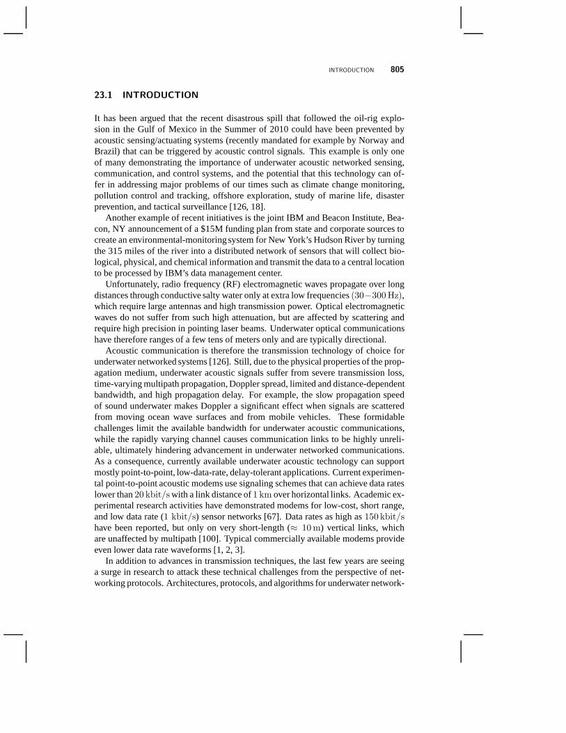
In typical underwater networks, a group of sensor nodes are anchored to the bottomof the ocean, and possibly interconnected to one or more underwater gateways bymeans of wireless acoustic links. The sensor network, usually through multi-hoppaths, relays data from the ocean bottom network to a surfacestation. Underwatergateways may be equipped with two acoustic transceivers, namely avertical and ahorizontal transceiver. The horizontal transceiver is used by the underwater gate-ways to communicate with the sensor nodes to send commands and configurationdata to the sensors and/or collect monitored data [111]. Thevertical link is used bythe underwater gateways to relay data to a surface station. In deep water applications,vertical transceivers are usually long-range transceivers. The surface station may beequipped with an acoustic transceiver able to handle multiple parallel communica-tions with the deployed underwater gateways and may communicate with anonshoresinkand/or to asurface sinkthrough a long-range radio transmitter and/or satellitetransmitter (see Fig. 23.1). Sensor nodes may float atdifferent depthsto observe agiven phenomenon. One possible solution is to attach each sensor node to a surfacebuoy, by means of wires whose length can be regulated to adjust the depth of eachsensor node. Although this solution enables easy and quick deployment of the sensornetwork, floating buoys may obstruct ships navigating on thesurface, or they can beeasily detected and deactivated by enemies in military settings. Furthermore, float-ing buoys are vulnerable to weather and tampering or pilfering. Typically, sensing
BASICS OF UNDERWATER COMMUNICATIONS 807
Figure 23.1 Architecture of an underwater acoustic sensor network.
devices are anchored to the bottom of the ocean, and are equipped with floatationcapabilities.
23.3 BASICS OF UNDERWATER COMMUNICATIONS
Typical physical carriers for underwater communication signals are RF electromag-netic waves, optical waves and acoustic waves. RF waves are affected by high atten-uation in water (especially at higher frequencies), thus requiring high transmissionpower and large antennas [16, 136, 61]. Therefore, RF waves are generally usedfor underwater communications over very short ranges (up to10 meters) [34, 68].Optical waves enable high data rate communications (in the order of a fewGbit/s)[55], but are rapidly scattered and absorbed in water, leading again to short-rangecommunications [41]. Acoustic waves, instead, may enable communications overlong-range links since they suffer from relatively low absorption. This has con-tributed to making acoustic transmission the most common underwater communica-tion technique since World War Two [17, 141, 126].
Still, Underwater Acoustic (UW-A) communications are severely affected byhighpath loss, noise, multipath, high and variable propagation delayandDoppler spread.The combined effect of these phenomena causes the UW-A channel to betemporallyandspatially variable. This limits the available bandwidth and makes it dramati-
808 ADVANCES IN UNDERWATER ACOUSTIC NETWORKING
cally dependent on both range and frequency. Short-range systems that operate overseveral tens of meters may have more than100 kHz of bandwidth, while long-rangesystems that operate over several tens of kilometers may have bandwidths of only afew kHz. Therefore, UW-A communication system mostly have low bit rates, whichare in the order of tens ofkbit/s [32].
Depending on their range, UW-A communication links can be classified asverylong, long, medium, short andvery short[126]. Typical bandwidths of underwaterlinks for various ranges are presented in Table 23.1. Acoustic links can also beroughly classified asvertical andhorizontalaccording to the direction of the soundray with respect to the ocean bottom. Propagation characteristics of the links varyconsiderably on multipath spreads, time dispersion and delay variance. The oceanicliterature typically refers toshallow wateras water with depth lower than100 m,while deep wateris used for deeper oceans [18].
Table 23.1 Available bandwidth for different ranges in UW-A channels.
Range [km] Bandwidth [kHz]
Very long 1000 < 1Long 10 - 100 2 - 5Medium 1 - 10 ≈10Short 0.1 - 1 20 - 50Very Short < 0.1 > 100
Below, we provide a detailed discussion of the factors that influence UW-A com-munications. These include:
• Transmission (Path) Loss:
Transmission loss is mainly caused by two phenomena:geometric spreadinglossandattenuation. Transmission loss for a signal of frequencyf [kHz] overa transmission distanced [m] can be expressed in [dB] as
10 logTL(d, f) = k · 10 log(d) + d · α(f) +A, (23.1)
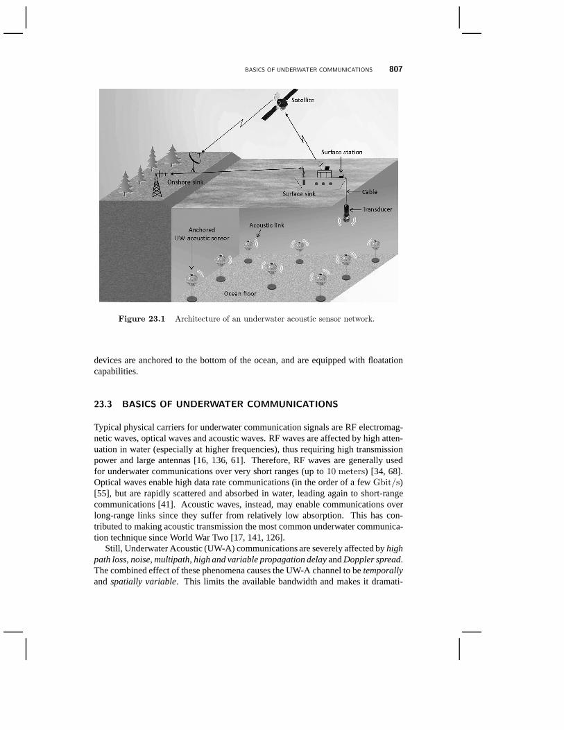
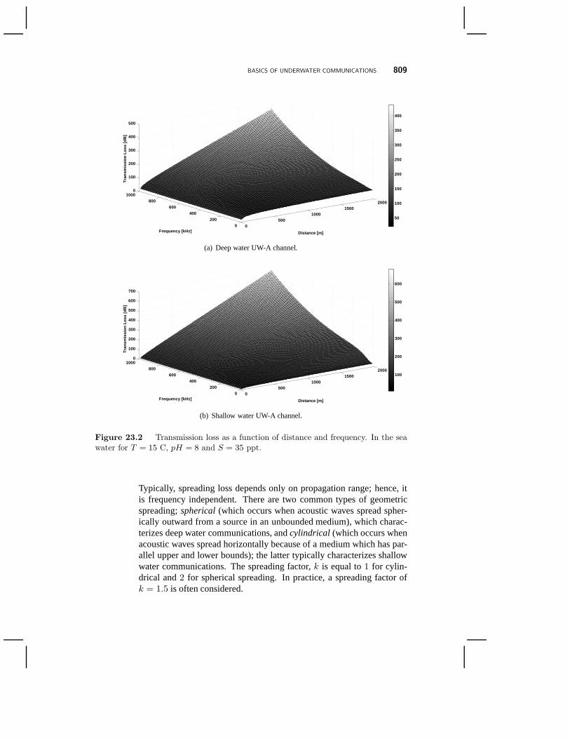
wherek is thespreading factor, which describes the geometry of propagation,α(f) [dB/m] is theabsorption coefficientandA [dB] is the so-calledtrans-mission anomalywhich accounts for factors other than absorption includingmultipath propagation, refraction, diffraction and scattering [141, 107]. Fig-ure 23.2 shows the transmission loss with varying frequencyand distance forshallow and deep water UW-A channels. The shallow water UW-Achannelhas higher values of attenuation than the deep water UW-A channel, whiletransmission loss increases with distance and frequency for both.
– Geometric Spreading Loss:Geometric Spreading Loss is caused by the spreading of acoustic energyto a larger surface as a consequence of the expansion of acoustic waves.
BASICS OF UNDERWATER COMMUNICATIONS 809
0500
10001500
2000
0200
400600
8001000
0
100
200
300
400
500
Distance [m] Frequency [kHz]
Tra
nsm
issi
on L
oss
[dB
]
50
100
150
200
250
300
350
400
(a) Deep water UW-A channel.
0500
10001500
2000
0200
400600
8001000
0
100
200
300
400
500
600
700
Distance [m] Frequency [kHz]
Tra
nsm
issi
on L
oss
[dB
]
100
200
300
400
500
600
(b) Shallow water UW-A channel.
Figure 23.2 Transmission loss as a function of distance and frequency. In the seawater for T = 15 C, pH = 8 and S = 35 ppt.
Typically, spreading loss depends only on propagation range; hence, itis frequency independent. There are two common types of geometricspreading;spherical(which occurs when acoustic waves spread spher-ically outward from a source in an unbounded medium), which charac-terizes deep water communications, andcylindrical (which occurs whenacoustic waves spread horizontally because of a medium which has par-allel upper and lower bounds); the latter typically characterizes shallowwater communications. The spreading factor,k is equal to1 for cylin-drical and2 for spherical spreading. In practice, a spreading factor ofk = 1.5 is often considered.

810 ADVANCES IN UNDERWATER ACOUSTIC NETWORKING
– Attenuation:
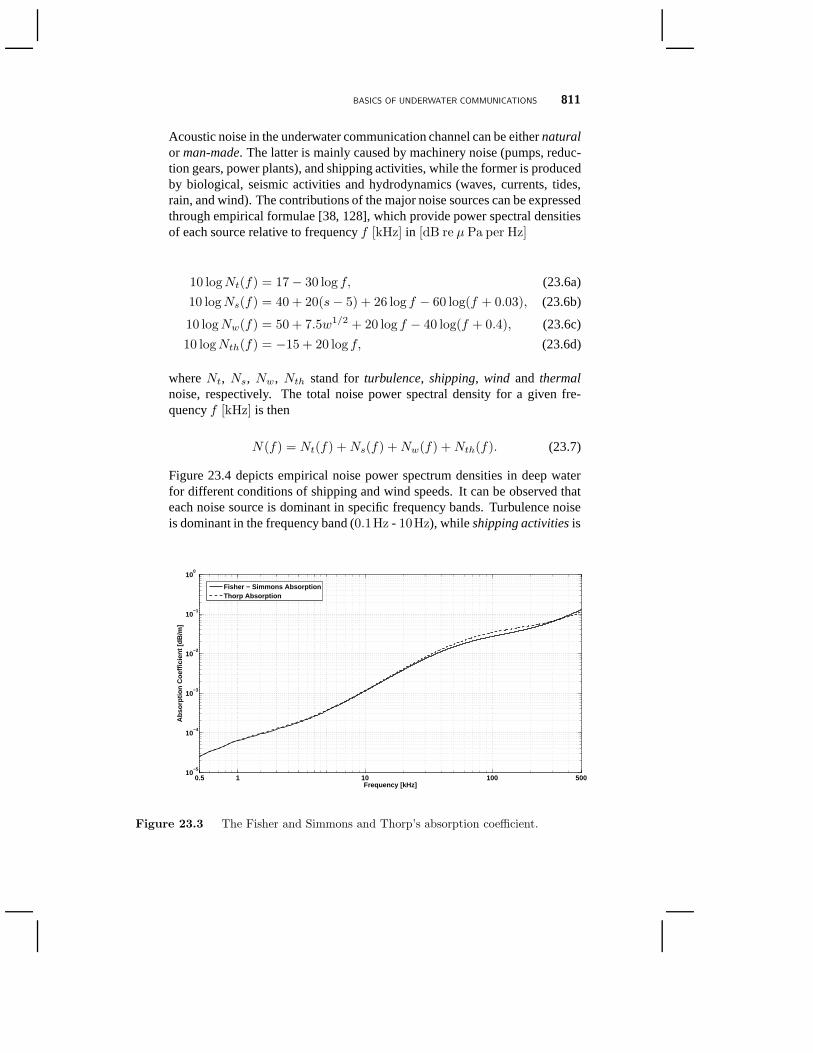
Attenuation can be mainly attributed to absorption, causedby conversionof energy of the propagating acoustic wave into heat (also referred to asabsorption loss). The absorption coefficient for frequencies above a fewhundredHz can be expressed empirically using Thorp’s formula [139],which definesα(f) [dB/m] as a function off [kHz]
α(f) = (0.11f2
f2 + 1+ 44
f2
f2 + 4100+ 2.75 · 10−4f2 +
+0.003) · 10−3. (23.2)
For lower frequencies, the absorption coefficient can be expressed as[128]
α(f) = (0.002 + 0.11f2
f2 + 1+ 0.011f2) · 10−3. (23.3)
An alternative expression for the absorption coefficientα(f) [dB/m] isgiven by the Fisher and Simmons formula [42]
α(f) = (A1P1
f2
f2
1+ f2
f1+A2P2
f2
f2
2+ f2
f2+A3P3f2)·10−3, (23.4)
where the three terms account for the effects of boric acid, magnesiumsulphate, and pure water, respectively. The termsA1, A2, A3, f1, andf2are somewhat complex functions of temperature, whileP1, P2, andP3
are functions of water pressure [141].
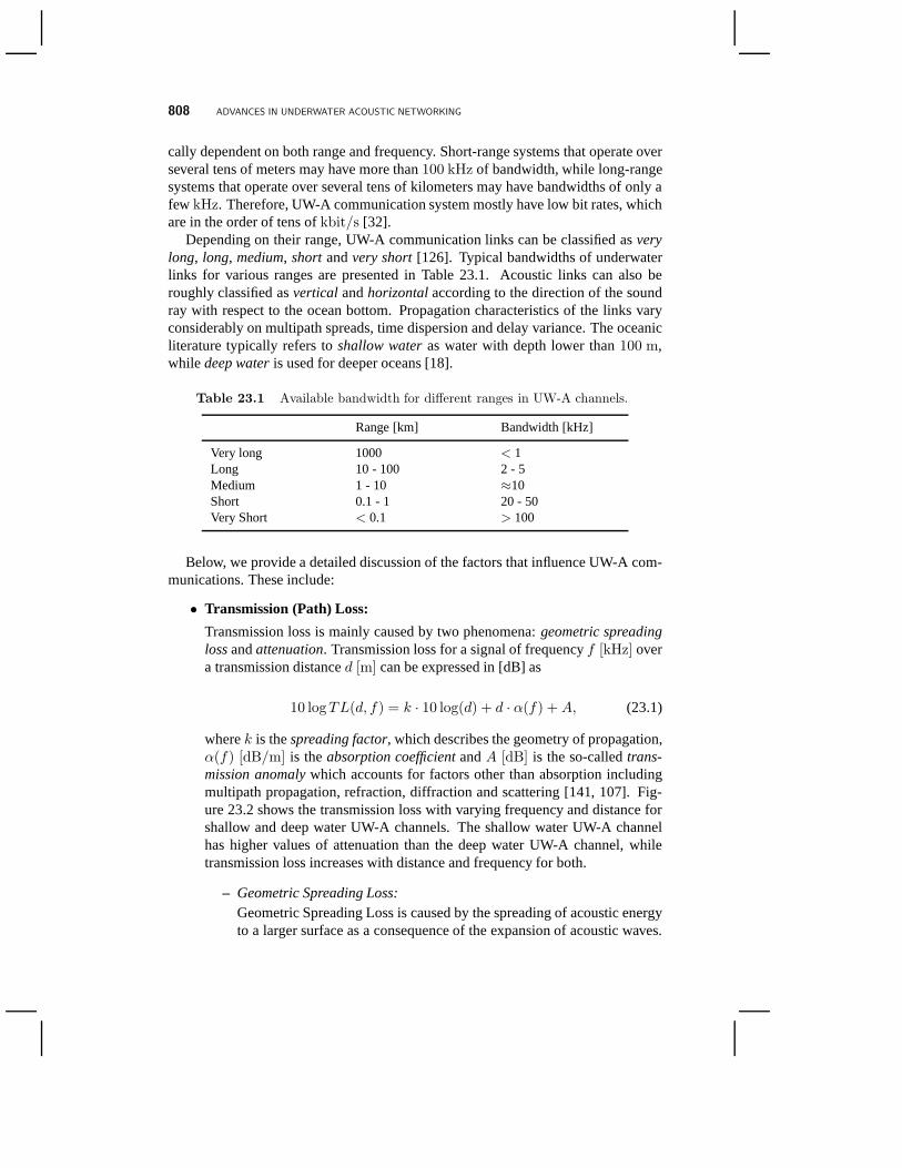
As seen in Fig. 23.3, the absorption coefficient is proportional to theoperating frequency. Therefore, absorption loss is strongly dependent onfrequency and distance. Moreover, water depth also plays a key role indetermining the level of attenuation, as absorption is affected by waterpressure [43]. This phenomenon can be modeled as
αd = α0(1− 1.93 · 10−5d), (23.5)
whereα0 andαd are the absorption coefficients at depth zero (d = 0)andd meters respectively at a water temperature of4 oC. Hence, the ab-sorption loss decreases in deep water [118]. As mentioned earlier, atten-uation is also provoked by multipath propagation, refraction, diffractionand scattering.
• Noise:
BASICS OF UNDERWATER COMMUNICATIONS 811
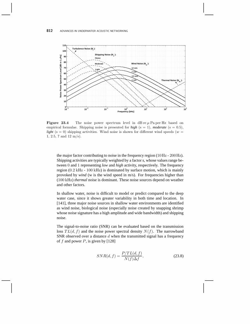
Acoustic noise in the underwater communication channel canbe eithernaturalor man-made. The latter is mainly caused by machinery noise (pumps, reduc-tion gears, power plants), and shipping activities, while the former is producedby biological, seismic activities and hydrodynamics (waves, currents, tides,rain, and wind). The contributions of the major noise sources can be expressedthrough empirical formulae [38, 128], which provide power spectral densitiesof each source relative to frequencyf [kHz] in [dB re µ Pa per Hz]
10 logNt(f) = 17− 30 log f, (23.6a)
10 logNs(f) = 40 + 20(s− 5) + 26 log f − 60 log(f + 0.03), (23.6b)
10 logNw(f) = 50 + 7.5w1/2 + 20 log f − 40 log(f + 0.4), (23.6c)
10 logNth(f) = −15 + 20 log f, (23.6d)
whereNt, Ns, Nw, Nth stand forturbulence, shipping, wind and thermalnoise, respectively. The total noise power spectral density for a given fre-quencyf [kHz] is then
N(f) = Nt(f) +Ns(f) +Nw(f) +Nth(f). (23.7)
Figure 23.4 depicts empirical noise power spectrum densities in deep waterfor different conditions of shipping and wind speeds. It canbe observed thateach noise source is dominant in specific frequency bands. Turbulence noiseis dominant in the frequency band (0.1Hz - 10Hz), whileshipping activitiesis
1 10 100 5000.510
−5
10−4
10−3
10−2
10−1
100
Frequency [kHz]
Abs
orpt
ion
Coe
ffici
ent [
dB/m
]
Fisher − Simmons AbsorptionThorp Absorption
Figure 23.3 The Fisher and Simmons and Thorp’s absorption coefficient.
812 ADVANCES IN UNDERWATER ACOUSTIC NETWORKING
10−3
10−2
10−1
100
101
102
103
0
10
20
30
40
50
60
70
80
90
100
110
Frequency [kHz]
Noi
se P
ower
Spe
ctru
m L
evel
[dB
re
1 µP
a]
Thermal Noise (Nth
):
Turbulence Noise (Nt ):
Shipping Noise (Ns ):
Heavy
Moderate
Light
Wind Noise (Nw
):
12 m/s
7 m/s
2.5 m/s
1 m/s
Figure 23.4 The noise power spectrum level in dB re µ Pa per Hz based onempirical formulae. Shipping noise is presented for high (s = 1), moderate(s = 0.5),light (s = 0) shipping activities. Wind noise is shown for different wind speeds (w =1, 2.5, 7 and 12 m/s).
the major factor contributing to noise in the frequency region (10Hz - 200Hz).Shipping activities are typically weighted by a factors, whose values range be-tween0 and1 representinglow andhighactivity, respectively. The frequencyregion (0.2 kHz - 100 kHz) is dominated by surface motion, which is mainlyprovoked bywind (w is the wind speed in m/s). For frequencies higher than(100 kHz) thermalnoise is dominant. These noise sources depend on weatherand other factors.
In shallow water, noise is difficult to model or predict compared to the deepwater case, since it shows greater variability in both time and location. In[141], three major noise sources in shallow water environments are identifiedas wind noise, biological noise (especially noise created by snapping shrimpwhose noise signature has a high amplitude and wide bandwidth) and shippingnoise.
The signal-to-noise ratio (SNR) can be evaluated based on the transmissionlossTL(d, f) and the noise power spectral densityN(f). The narrowbandSNR observed over a distanced when the transmitted signal has a frequencyof f and powerP , is given by [128]
SNR(d, f) =P/TL(d, f)
N(f)∆f, (23.8)
BASICS OF UNDERWATER COMMUNICATIONS 813
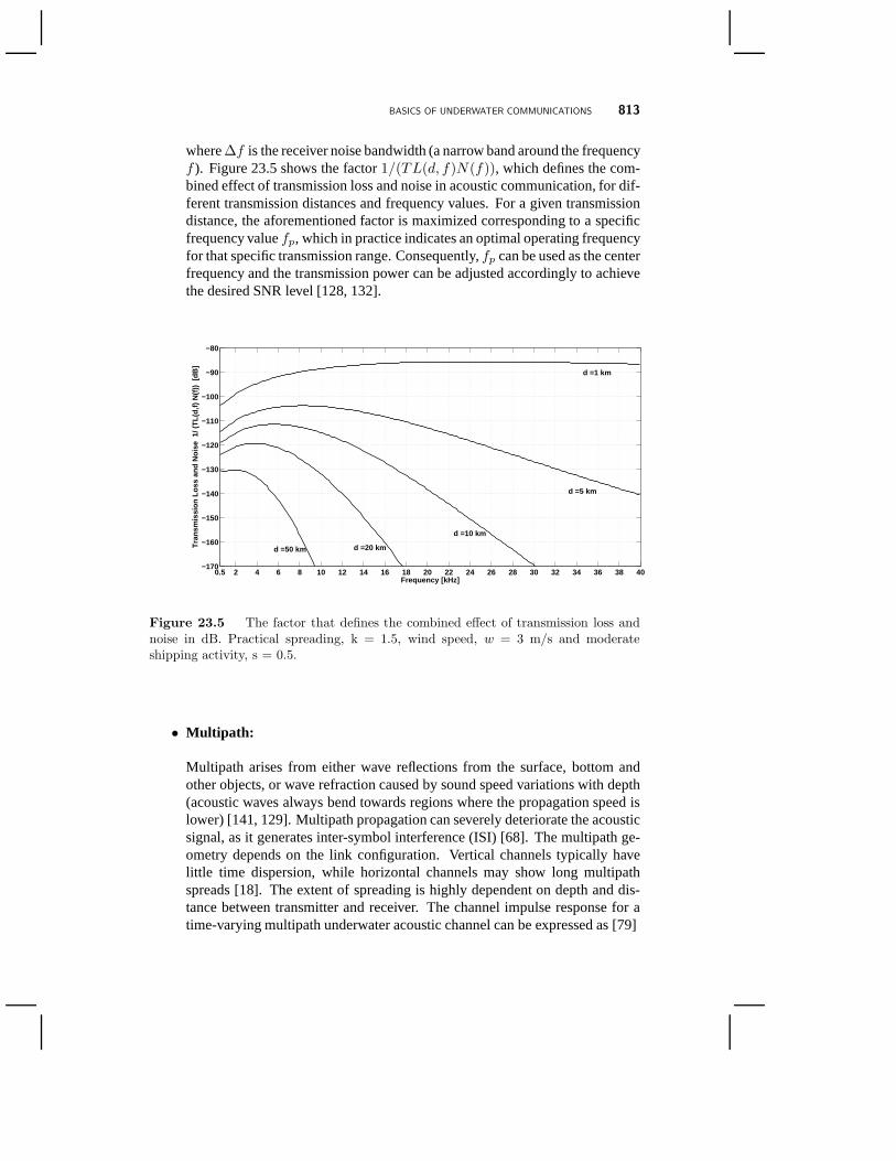
where∆f is the receiver noise bandwidth (a narrow band around the frequencyf ). Figure 23.5 shows the factor1/(TL(d, f)N(f)), which defines the com-bined effect of transmission loss and noise in acoustic communication, for dif-ferent transmission distances and frequency values. For a given transmissiondistance, the aforementioned factor is maximized corresponding to a specificfrequency valuefp, which in practice indicates an optimal operating frequencyfor that specific transmission range. Consequently,fp can be used as the centerfrequency and the transmission power can be adjusted accordingly to achievethe desired SNR level [128, 132].
0.5 2 4 6 8 10 12 14 16 18 20 22 24 26 28 30 32 34 36 38 40−170
−160
−150
−140
−130
−120
−110
−100
−90
−80
Frequency [kHz]
Tra
nsm
issi
on L
oss
and
Noi
se 1
/ (T
L(d,
f) N
(f))
[dB
] d =1 km
d =5 km
d =10 km
d =50 km d =20 km
Figure 23.5 The factor that defines the combined effect of transmission loss andnoise in dB. Practical spreading, k = 1.5, wind speed, w = 3 m/s and moderateshipping activity, s = 0.5.
• Multipath:
Multipath arises from either wave reflections from the surface, bottom andother objects, or wave refraction caused by sound speed variations with depth(acoustic waves always bend towards regions where the propagation speed islower) [141, 129]. Multipath propagation can severely deteriorate the acousticsignal, as it generates inter-symbol interference (ISI) [68]. The multipath ge-ometry depends on the link configuration. Vertical channelstypically havelittle time dispersion, while horizontal channels may showlong multipathspreads [18]. The extent of spreading is highly dependent ondepth and dis-tance between transmitter and receiver. The channel impulse response for atime-varying multipath underwater acoustic channel can beexpressed as [79]
814 ADVANCES IN UNDERWATER ACOUSTIC NETWORKING
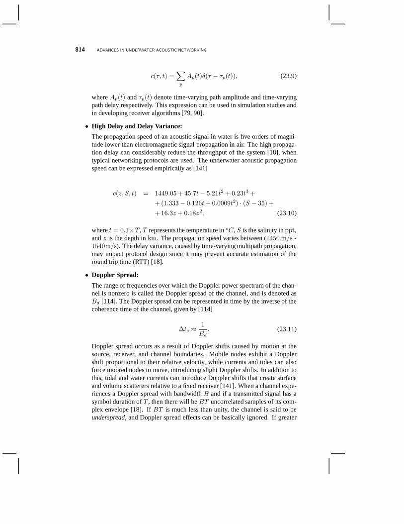
c(τ, t) =∑
p
Ap(t)δ(τ − τp(t)), (23.9)
whereAp(t) andτp(t) denote time-varying path amplitude and time-varyingpath delay respectively. This expression can be used in simulation studies andin developing receiver algorithms [79, 90].
• High Delay and Delay Variance:
The propagation speed of an acoustic signal in water is five orders of magni-tude lower than electromagnetic signal propagation in air.The high propaga-tion delay can considerably reduce the throughput of the system [18], whentypical networking protocols are used. The underwater acoustic propagationspeed can be expressed empirically as [141]
c(z, S, t) = 1449.05 + 45.7t− 5.21t2 + 0.23t3 +
+(1.333− 0.126t+ 0.0009t2) · (S − 35) +
+16.3z + 0.18z2, (23.10)
wheret = 0.1×T ,T represents the temperature inoC, S is the salinity inppt,andz is the depth inkm. The propagation speed varies between (1450 m/s -1540m/s). The delay variance, caused by time-varying multipath propagation,may impact protocol design since it may prevent accurate estimation of theround trip time (RTT) [18].
• Doppler Spread:
The range of frequencies over which the Doppler power spectrum of the chan-nel is nonzero is called the Doppler spread of the channel, and is denoted asBd [114]. The Doppler spread can be represented in time by the inverse of thecoherence time of the channel, given by [114]
∆tc ≈1
Bd. (23.11)
Doppler spread occurs as a result of Doppler shifts caused bymotion at thesource, receiver, and channel boundaries. Mobile nodes exhibit a Dopplershift proportional to their relative velocity, while currents and tides can alsoforce moored nodes to move, introducing slight Doppler shifts. In addition tothis, tidal and water currents can introduce Doppler shiftsthat create surfaceand volume scatterers relative to a fixed receiver [141]. When a channel expe-riences a Doppler spread with bandwidthB and if a transmitted signal has asymbol duration ofT , then there will beBT uncorrelated samples of its com-plex envelope [18]. IfBT is much less than unity, the channel is said to beunderspread, and Doppler spread effects can be basically ignored. If greater
PHYSICAL LAYER 815
than unity, it is said to beoverspread[68]. The Doppler spread can be signifi-cant in UW-A channels [126], thus causing degradation in theperformance ofdigital communications. ISI occurs at the receiver with high data rate transmis-sion. Doppler spreading generates two different effects onsignals: a simplefrequency translation, which is relatively easy for a receiver to compensate for,and a continuous spreading of frequencies that creates a non-shifted signal.
23.4 PHYSICAL LAYER
The physical (PHY) layer encompasses functionalities likemodulation, error correc-tion and channel equalization for reliable transmission ofdigital bit streams. The keychallenge underlying the PHY layer is to design spectrally efficient yet robust modu-lation schemes and receivers to exploit the limited bandwidth available in the under-water acoustic channel. This challenging objective has resulted in extensive research,whose developments we describe in this section. Specifically, in Section 23.4.1, wediscuss non-coherent modulation techniques, which were initially used as a low-complexity, practical technique for underwater acoustic communications. In Section23.4.2, we discuss coherent modulation methods, which are used to increase thespectral efficiency with respect to non-coherent methods. In Section 23.4.3, we dis-cuss recent developments on channel equalization techniques. In Section 23.4.4, welook at the state of the art in direct-sequence spread-spectrum transmission schemesapplied to underwater communications, while in Section 23.4.5, we discuss multi-carrier modulation schemes. Finally, in Section 23.4.6, wereview advancements inspatial-modulation techniques.
23.4.1 Non-Coherent Modulation
In the early years of underwater acoustic communications researchers in the fieldmainly focused on non-coherent modulation methods due to their simplicity, reliabil-ity and robustness. In particular, frequency-shift keying(FSK) modulation schemesbased on energy detection were favored since FSK modulationdoes not requirecarrier-phase tracking. Shallow water as well as long- and medium-range underwa-ter acoustic channels show rapid phase variations mainly due to the Doppler spreadcaused by mobility of the acoustic medium and as a result phase tracking is very chal-lenging [125, 18]. Multipath effects in underwater acoustic channel, which result inISI, can be suppressed by inserting guard times between successive symbols to en-sure that all the reverberations caused by the rough ocean surface and bottom vanishbefore the next symbol is received [18]. To adapt the communication to the Dopplerspread of the underwater acoustic channel dynamic frequency guards with varyingguard times may be used [18]. The insertion of guard intervals evidently diminishesthe overall achievable data rate. Selection of an appropriate length of the guard inter-val is therefore very important to identify the right tradeoff between ISI suppressionand achievable data rates. Moreover, since fading is correlated among frequenciesseparated by less than the coherence bandwidth,Bc = 1/Tm (whereTm repre-
816 ADVANCES IN UNDERWATER ACOUSTIC NETWORKING
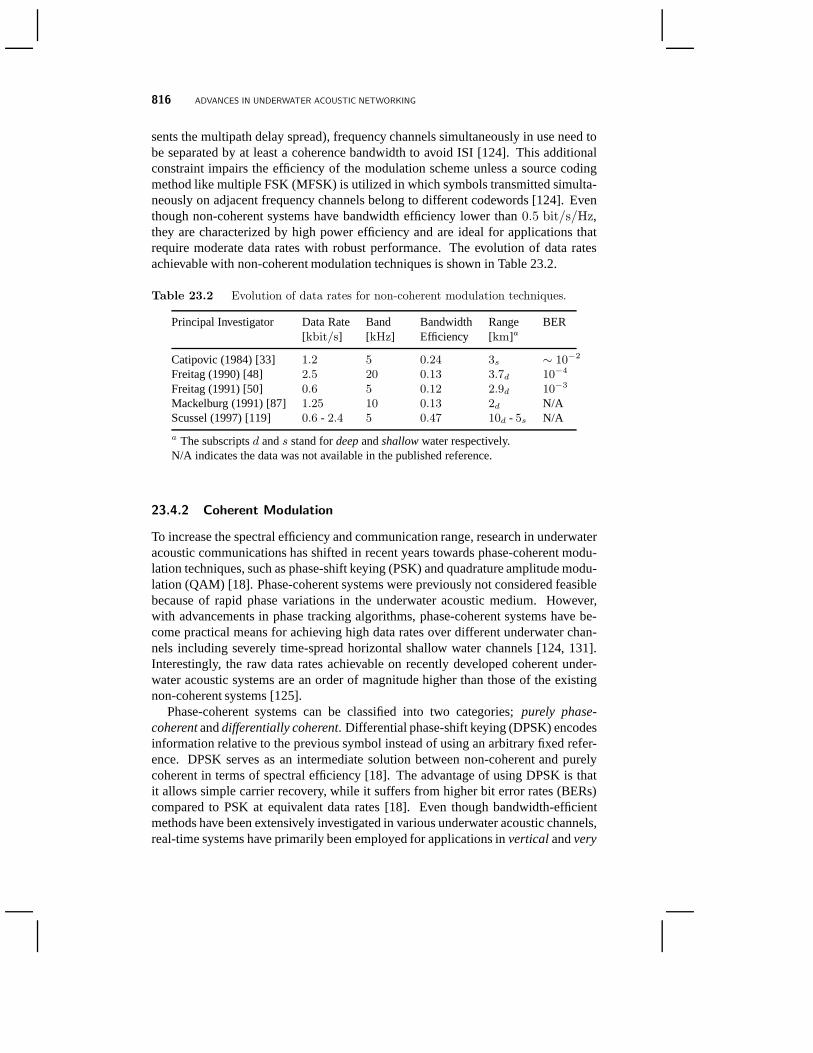
sents the multipath delay spread), frequency channels simultaneously in use need tobe separated by at least a coherence bandwidth to avoid ISI [124]. This additionalconstraint impairs the efficiency of the modulation scheme unless a source codingmethod like multiple FSK (MFSK) is utilized in which symbolstransmitted simulta-neously on adjacent frequency channels belong to differentcodewords [124]. Eventhough non-coherent systems have bandwidth efficiency lower than0.5 bit/s/Hz,they are characterized by high power efficiency and are idealfor applications thatrequire moderate data rates with robust performance. The evolution of data ratesachievable with non-coherent modulation techniques is shown in Table 23.2.
Table 23.2 Evolution of data rates for non-coherent modulation techniques.
Principal Investigator Data Rate[kbit/s]
Band[kHz]
BandwidthEfficiency
Range[km]a
BER
Catipovic (1984) [33] 1.2 5 0.24 3s ∼ 10−2
Freitag (1990) [48] 2.5 20 0.13 3.7d 10−4
Freitag (1991) [50] 0.6 5 0.12 2.9d 10−3
Mackelburg (1991) [87] 1.25 10 0.13 2d N/AScussel (1997) [119] 0.6 - 2.4 5 0.47 10d - 5s N/A
a The subscriptsd ands stand fordeepandshallowwater respectively.N/A indicates the data was not available in the published reference.
23.4.2 Coherent Modulation
To increase the spectral efficiency and communication range, research in underwateracoustic communications has shifted in recent years towards phase-coherent modu-lation techniques, such as phase-shift keying (PSK) and quadrature amplitude modu-lation (QAM) [18]. Phase-coherent systems were previouslynot considered feasiblebecause of rapid phase variations in the underwater acoustic medium. However,with advancements in phase tracking algorithms, phase-coherent systems have be-come practical means for achieving high data rates over different underwater chan-nels including severely time-spread horizontal shallow water channels [124, 131].Interestingly, the raw data rates achievable on recently developed coherent under-water acoustic systems are an order of magnitude higher thanthose of the existingnon-coherent systems [125].
Phase-coherent systems can be classified into two categories; purely phase-coherentanddifferentially coherent. Differential phase-shift keying (DPSK) encodesinformation relative to the previous symbol instead of using an arbitrary fixed refer-ence. DPSK serves as an intermediate solution between non-coherent and purelycoherent in terms of spectral efficiency [18]. The advantageof using DPSK is thatit allows simple carrier recovery, while it suffers from higher bit error rates (BERs)compared to PSK at equivalent data rates [18]. Even though bandwidth-efficientmethods have been extensively investigated in various underwater acoustic channels,real-time systems have primarily been employed for applications inverticalandvery
PHYSICAL LAYER 817
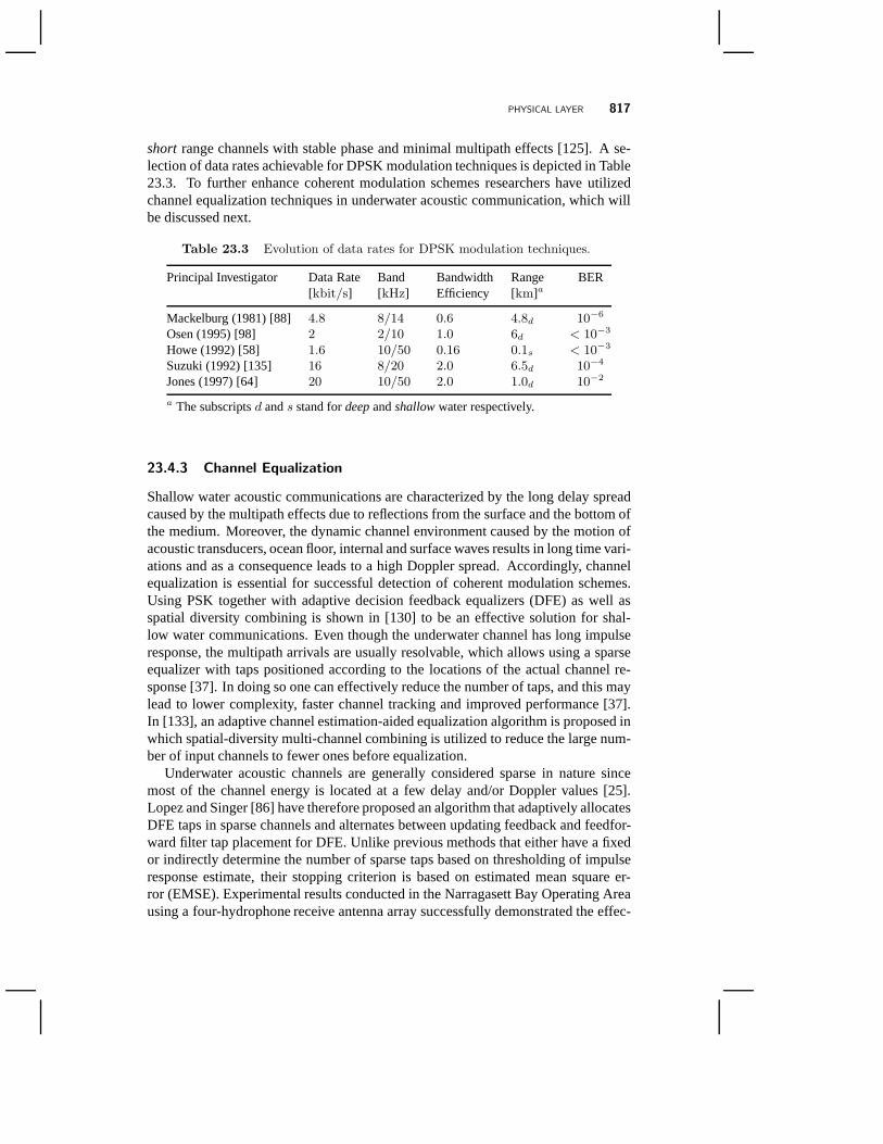
short range channels with stable phase and minimal multipath effects [125]. A se-lection of data rates achievable for DPSK modulation techniques is depicted in Table23.3. To further enhance coherent modulation schemes researchers have utilizedchannel equalization techniques in underwater acoustic communication, which willbe discussed next.
Table 23.3 Evolution of data rates for DPSK modulation techniques.
Principal Investigator Data Rate[kbit/s]
Band[kHz]
BandwidthEfficiency
Range[km]a
BER
Mackelburg (1981) [88] 4.8 8/14 0.6 4.8d 10−6
Osen (1995) [98] 2 2/10 1.0 6d < 10−3
Howe (1992) [58] 1.6 10/50 0.16 0.1s < 10−3
Suzuki (1992) [135] 16 8/20 2.0 6.5d 10−4
Jones (1997) [64] 20 10/50 2.0 1.0d 10−2
a The subscriptsd ands stand fordeepandshallowwater respectively.
23.4.3 Channel Equalization
Shallow water acoustic communications are characterized by the long delay spreadcaused by the multipath effects due to reflections from the surface and the bottom ofthe medium. Moreover, the dynamic channel environment caused by the motion ofacoustic transducers, ocean floor, internal and surface waves results in long time vari-ations and as a consequence leads to a high Doppler spread. Accordingly, channelequalization is essential for successful detection of coherent modulation schemes.Using PSK together with adaptive decision feedback equalizers (DFE) as well asspatial diversity combining is shown in [130] to be an effective solution for shal-low water communications. Even though the underwater channel has long impulseresponse, the multipath arrivals are usually resolvable, which allows using a sparseequalizer with taps positioned according to the locations of the actual channel re-sponse [37]. In doing so one can effectively reduce the number of taps, and this maylead to lower complexity, faster channel tracking and improved performance [37].In [133], an adaptive channel estimation-aided equalization algorithm is proposed inwhich spatial-diversity multi-channel combining is utilized to reduce the large num-ber of input channels to fewer ones before equalization.
Underwater acoustic channels are generally considered sparse in nature sincemost of the channel energy is located at a few delay and/or Doppler values [25].Lopez and Singer [86] have therefore proposed an algorithm that adaptively allocatesDFE taps in sparse channels and alternates between updatingfeedback and feedfor-ward filter tap placement for DFE. Unlike previous methods that either have a fixedor indirectly determine the number of sparse taps based on thresholding of impulseresponse estimate, their stopping criterion is based on estimated mean square er-ror (EMSE). Experimental results conducted in the Narragasett Bay Operating Areausing a four-hydrophone receive antenna array successfully demonstrated the effec-
818 ADVANCES IN UNDERWATER ACOUSTIC NETWORKING
tiveness of the algorithm, which utilizes on average10 feedforward taps per arrayelement and25 feedback taps. For shallow water environments, this numberof tapsis considerably smaller than the required taps for conventional DFE. More recently,Weichang and Preisig [84] developed a sparse channel estimation technique basedon the delay-Doppler spread function representation of thechannel to account forthe time variation of the impulse response. The channel impulse response is con-secutively estimated by selecting the dominant componentsthat minimize the meansquare error. The benefit of this method is that it captures the channel structure andits dynamics simultaneously without the need for explicit channel modeling. Theproposed method is compared with non-sparse recursive least square (RLS) estima-tion and sparse channel impulse response estimation. Through experimental resultsthe proposed method demonstrated a3 dB reduction in signal prediction error.
Conventional equalization algorithms are supervised and require transmission ofa training data sequence to enable the receiver to estimate the channel. In applica-tions where long streams of data packets are transmitted over time invariant channelthe overhead incurred by the pilot bits is insignificant. On the other hand, if shortdata packets are preferred for transmission or the channel is strongly time-varying,then the overhead from the training sequence could be significant. In such applica-tions unsupervised (blind) equalization algorithms may beused. However, the latternormally converge slower than supervised ones and as a result their use is limited totransmission of long streams of data packets. In [76], the authors demonstrated thatfor short data record combining blind adaptive DFE with an iterative algorithm mayreduce BER, hence performance may be improved.
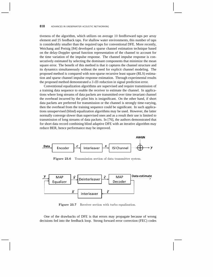
Figure 23.6 Transmission section of data transmitter system.
Figure 23.7 Receiver section with turbo equalization.
One of the drawbacks of DFE is that errors may propagate because of wrongdecisions fed into the feedback loop. Strong forward error correction (FEC) codes
PHYSICAL LAYER 819
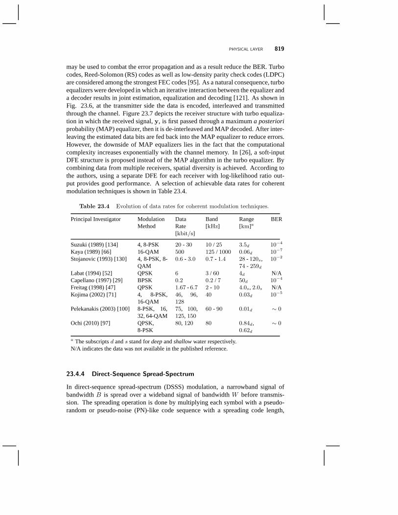
may be used to combat the error propagation and as a result reduce the BER. Turbocodes, Reed-Solomon (RS) codes as well as low-density parity check codes (LDPC)are considered among the strongest FEC codes [95]. As a natural consequence, turboequalizers were developed in which an iterative interaction between the equalizer anda decoder results in joint estimation, equalization and decoding [121]. As shown inFig. 23.6, at the transmitter side the data is encoded, interleaved and transmittedthrough the channel. Figure 23.7 depicts the receiver structure with turbo equaliza-tion in which the received signal,y, is first passed through a maximuma posterioriprobability (MAP) equalizer, then it is de-interleaved andMAP decoded. After inter-leaving the estimated data bits are fed back into the MAP equalizer to reduce errors.However, the downside of MAP equalizers lies in the fact thatthe computationalcomplexity increases exponentially with the channel memory. In [26], a soft-inputDFE structure is proposed instead of the MAP algorithm in theturbo equalizer. Bycombining data from multiple receivers, spatial diversityis achieved. According tothe authors, using a separate DFE for each receiver with log-likelihood ratio out-put provides good performance. A selection of achievable data rates for coherentmodulation techniques is shown in Table 23.4.
Table 23.4 Evolution of data rates for coherent modulation techniques.
Principal Investigator ModulationMethod
DataRate[kbit/s]
Band[kHz]
Range[km]a
BER
Suzuki (1989) [134] 4, 8-PSK 20 - 30 10 / 25 3.5d 10−4
Kaya (1989) [66] 16-QAM 500 125 / 1000 0.06d 10−7
Stojanovic (1993) [130] 4, 8-PSK, 8-QAM
0.6 - 3.0 0.7 - 1.4 28 - 120s,74 - 259d
10−2
Labat (1994) [52] QPSK 6 3 / 60 4d N/ACapellano (1997) [29] BPSK 0.2 0.2 / 7 50d 10−4
Freitag (1998) [47] QPSK 1.67 - 6.7 2 - 10 4.0s, 2.0s N/AKojima (2002) [71] 4, 8-PSK,
16-QAM46, 96,128
40 0.03d 10−5
Pelekanakis (2003) [100] 8-PSK, 16,32, 64-QAM
75, 100,125, 150
60 - 90 0.01d ∼ 0
Ochi (2010) [97] QPSK,8-PSK
80, 120 80 0.84d,0.62d
∼ 0
a The subscriptsd ands stand fordeepandshallowwater respectively.N/A indicates the data was not available in the published reference.
23.4.4 Direct-Sequence Spread-Spectrum
In direct-sequence spread-spectrum (DSSS) modulation, a narrowband signal ofbandwidthB is spread over a wideband signal of bandwidthW before transmis-sion. The spreading operation is done by multiplying each symbol with a pseudo-random or pseudo-noise (PN)-like code sequence with a spreading code length,

820 ADVANCES IN UNDERWATER ACOUSTIC NETWORKING
L = W/B and transmitting the generated signal at a higher rate. At the receiver side,the received signal is de-spread, using the same spreading code, before decoding.Multiuser communication may be supported by assigning eachuser with a uniquespreading sequence with good autocorrelation and cross-correlation properties thatcan resist interference from multiple users. DSSS, also known as direct-sequencecode-division multiple-access (DS-CDMA), has many characteristics that make it anappealing modulation (and multiple access) scheme for underwater acoustic commu-nications. One of the properties of DS-CDMA is that it is resilient to adversary jam-mer and can therefore enable covert communications. Besides, DS-CDMA has morerelaxed synchronization requirements compared to Time Division Multiple Access(TDMA) schemes. Moreover, DS-CDMA combined with a RAKE receiver may beused to combat the multipath fading acoustic channel. In non-coherent DS-CDMA,each user detects the signal of interest by matched-filtering the received signal andperforming energy detection. Coherent DS-CDMA is more involved as it may re-quire channel estimation and phase tracking before de-spreading and decoding theinformation bits [49]. The spreading operation of DS-CDMA may affect the achiev-able data rates. For bandwidths of severalkHz, the data rates are in the order ofhundreds ofbit/s, which results in bandwidth efficiency lower than0.5 bit/s/Hz[85].
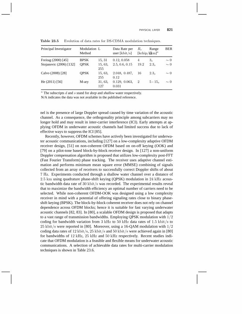
Due to the highly-frequency selective distortion caused bymultipath propagation,it would be useful, if not essential, to employ DFE in DS-CDMAreceiver design. In[132], Stojanovic and Freitag propose two types of DFEs, a symbol decision feed-back (SDF) receiver and a chip hypothesis feedback (CHF) receiver. SDF feedbackequalization is adapted at the symbol level, which makes useof the symbol decisionsafter being de-spread on the feedback path. For highly time varying channels, CHFfeedback equalization is utilized instead. The latter tracks the channel at the chip rate,Rc, at the price of an increase in computational complexity. Inmore recent workthe authors in [19] proposed two iterative DFE receivers, DFE-IDMA (interleave-division multiple access) and DFE-CDMA. Both of the single-element receivers uti-lize chip-level adaptive DFE, carrier phase tracking together with iterative interfer-ence cancellation (IC) and channel coding. The experimental results show that theproposed adaptive receivers outperform channel estimation based RAKE receiversand maintain lower complexity. The achievable data rates ofsome DS-CDMA mod-ulation techniques is shown in Table 23.5.
23.4.5 Multi-Carrier Modulation
A possible way to overcome the long delay-spread in underwater communicationis to use multi-carrier modulation schemes such as orthogonal frequency-divisionmultiplexing (OFDM) [120]. Multi-carrier processing mapsthe frequency selectivechannel into a set of flat-fading sub channels. Accordingly,equalization may be doneby multiplying each flat-fading channel output by a single complex tap value. As aresult, long equalization filters required to combat ISI maybe avoided and hence thecomplexity of the receiver design may be reduced significantly [120]. However, themajor challenge in applying multi-carrier modulation for underwater acoustic chan-
PHYSICAL LAYER 821
Table 23.5 Evolution of data rates for DS-CDMA modulation techniques.
Principal Investigator ModulationMethod
L Data Rate peruser [kbit/s]
Rc
[kchip/s]Range[km]a
BER
Freitag (2000) [45] BPSK 15, 31 0.12, 0.058 4 3s ∼ 0
Stojanovic (2006) [132] QPSK 15, 63,255
2.5, 0.6, 0.15 19.2 2.3s ∼ 0
Calvo (2008) [28] QPSK 15, 63,255
2.048, 0.487,0.12
16 2.3s ∼ 0
He (2011) [56] M-ary 31, 63,127
0.129, 0.063,0.031
2 5 - 15s ∼ 0
a The subscriptsd ands stand fordeepandshallowwater respectively.N/A indicates the data was not available in the published reference.
nel is the presence of large Doppler spread caused by time variation of the acousticchannel. As a consequence, the orthogonality principle among subcarriers may nolonger hold and may result in inter-carrier interference (ICI). Early attempts at ap-plying OFDM in underwater acoustic channels had limited success due to lack ofeffective ways to suppress the ICI [85].
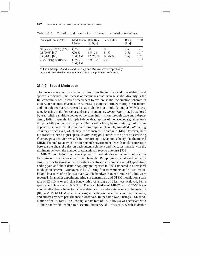
Recently, however, OFDM schemes have actively been investigated for underwa-ter acoustic communications, including [127] on a low-complexity adaptive OFDMreceiver design, [51] on non-coherent OFDM based on on-off keying (OOK) and[79] on a pilot-tone based block-by-block receiver design.In [127] a non-uniformDoppler compensation algorithm is proposed that utilizes low-complexity post-FFT(Fast Fourier Transform) phase tracking. The receiver usesadaptive channel esti-mation and performs minimum mean square error (MMSE) combining of signalscollected from an array of receivers to successfully correct Doppler shifts of about7 Hz. Experiments conducted through a shallow water channel over a distance of2.5 km using quadrature phase-shift keying (QPSK) modulation in24 kHz acous-tic bandwidth data rate of30 kbit/s was recorded. The experimental results revealthat to maximize the bandwidth efficiency an optimal number of carriers need to beselected. While non-coherent OFDM-OOK was designed using alow complexityreceiver in mind with a potential of offering signaling rates close to binary phase-shift keying (BPSK). The block-by-block coherent receiverdoes not rely on channeldependence across OFDM blocks; hence it is suitable for fastvarying underwateracoustic channels [82, 83]. In [80], a scalable OFDM design is proposed that adaptsto a vast range of transmission bandwidths. Employing QPSK modulation with1/2coding for bandwidth variation from3 kHz to 50 kHz data rates of1.5 kbit/s to25 kbit/s were reported in [80]. Moreover, using a 16-QAM modulation with 1/2coding data rates of12 kbit/s, 25 kbit/s and50 kbit/s were achieved again in [80]for bandwidths of12 kHz, 25 kHz and50 kHz respectively. Recent studies indi-cate that OFDM modulation is a feasible and flexible means forunderwater acousticcommunications. A selection of achievable data rates for multi-carrier modulationtechniques is shown in Table 23.6.
822 ADVANCES IN UNDERWATER ACOUSTIC NETWORKING
Table 23.6 Evolution of data rates for multi-carrier modulation techniques.
Principal Investigator ModulationMethod
Data Rate[kbit/s]
Band [kHz] Range[km]a
BER
Stojanovic (2006) [127] QPSK 30 24 2.5s ∼ 0
Li (2008) [80] QPSK 1.5 - 25 3 - 50 0.5d 10−5
Li (2008) [80] 16-QAM 12, 25, 50 12, 25, 50 0.5d 10−5
J.-Z. Huang (2010) [60] QPSK,16-QAM
5.2, 10.4 9.77 1s 10−3
a The subscriptsd ands stand fordeepandshallowwater respectively.N/A indicates the data was not available in the published reference.
23.4.6 Spatial Modulation
The underwater acoustic channel suffers from limited bandwidth availability andspectral efficiency. The success of techniques that leverage spatial diversity in theRF community has inspired researchers to explore spatial modulation schemes inunderwater acoustic channels. A wireless system that utilizes multiple transmittersand multiple receivers is referred to as multiple-input-multiple-output (MIMO) sys-tem. By using multiple receive and transmit antennas,diversity gainmay be exploredby transmitting multiple copies of the same information through different indepen-dently fading channels. Multiple independent replicas of the received signal increasethe probability of correct reception. On the other hand, by transmitting multiple in-dependent streams of information through spatial channels, so-calledmultiplexinggainmay be achieved, which may lead to increase in data rate [146]. However, thereis a tradeoff since a higher spatialmultiplexing gaincomes at the price of sacrificingdiversity gainand vice versa [146]. According to Shannon’s theory, the theoreticalMIMO channel capacity in a scattering-rich environment depends on the correlationbetween the channel gains on each antenna element and increases linearly with theminimum between the number of transmit and receive antennas[53].
MIMO modulation has been explored in both single-carrier and multi-carriertransmission in underwater acoustic channels. By applyingspatial modulation onsingle carrier transmission with existing equalization techniques, a5 dB space-timecoding gain and about double capacity are reported in [69] compared to a temporalmodulation scheme. Moreover, in [117] using four transmitters and QPSK modu-lation, data rates of48 kbit/s over23 kHz bandwidth over a range of2 km werereported. In another experiment using six transmitters andQPSK modulation a datarate of12 kbit/s over3 kHz bandwidth over a range of2 km was achieved, i.e., aspectral efficiency of4 bit/s/Hz. The combination of MIMO with OFDM is yetanother attractive scheme to increase data rates in underwater acoustic channels. In[81], a MIMO-OFDM scheme is designed with two transmitters and four receivers,and almost errorless performance is observed. In the same work, using QPSK mod-ulation after 1/2 rate LDPC coding, a data rate of12.18 kbit/s was achieved with12 kHz bandwidth leading to a spectral efficiency of1 bit/s/Hz, which is double
MEDIUM ACCESS CONTROL LAYER 823
the efficiency compared to single transmission in [83] with the same modulation andcoding scheme.
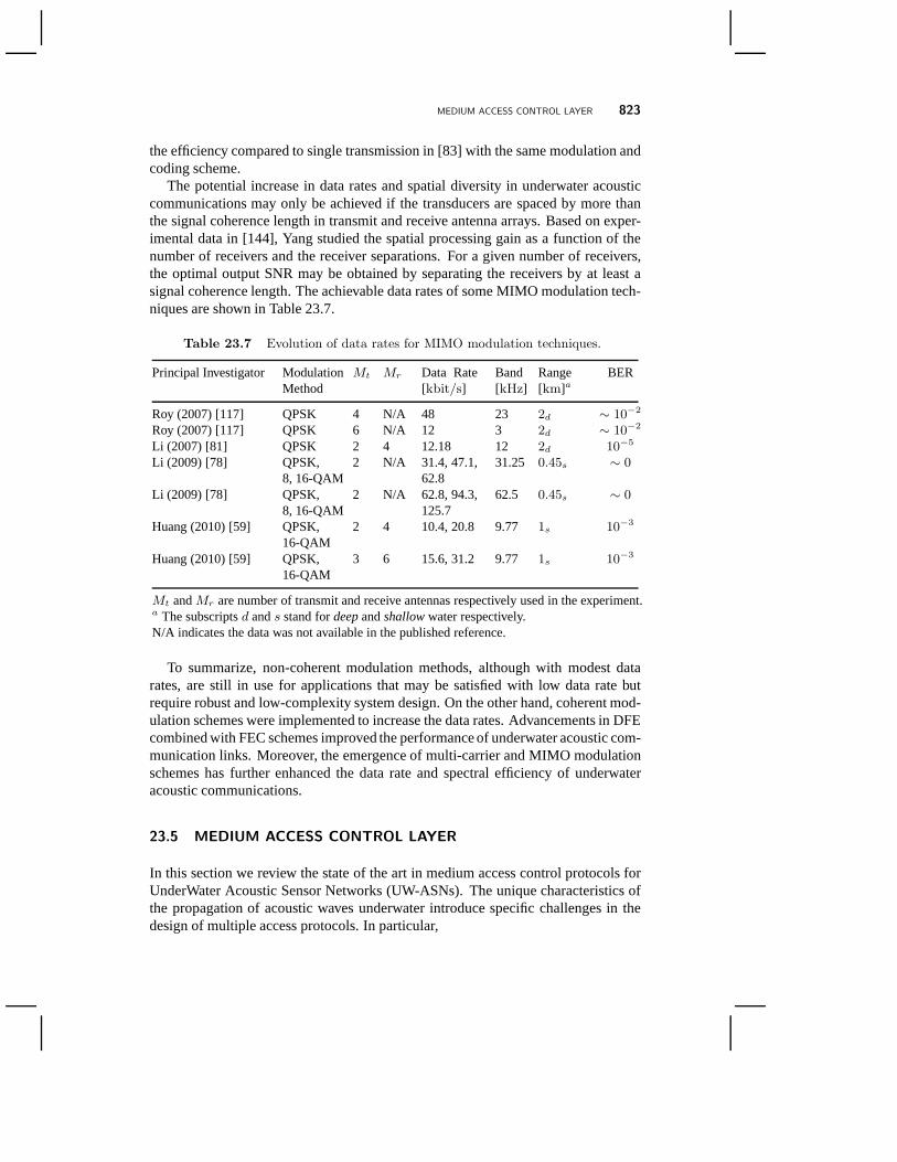
The potential increase in data rates and spatial diversity in underwater acousticcommunications may only be achieved if the transducers are spaced by more thanthe signal coherence length in transmit and receive antennaarrays. Based on exper-imental data in [144], Yang studied the spatial processing gain as a function of thenumber of receivers and the receiver separations. For a given number of receivers,the optimal output SNR may be obtained by separating the receivers by at least asignal coherence length. The achievable data rates of some MIMO modulation tech-niques are shown in Table 23.7.
Table 23.7 Evolution of data rates for MIMO modulation techniques.
Principal Investigator ModulationMethod
Mt Mr Data Rate[kbit/s]
Band[kHz]
Range[km]a
BER
Roy (2007) [117] QPSK 4 N/A 48 23 2d ∼ 10−2
Roy (2007) [117] QPSK 6 N/A 12 3 2d ∼ 10−2
Li (2007) [81] QPSK 2 4 12.18 12 2d 10−5
Li (2009) [78] QPSK,8, 16-QAM
2 N/A 31.4, 47.1,62.8
31.25 0.45s ∼ 0
Li (2009) [78] QPSK,8, 16-QAM
2 N/A 62.8, 94.3,125.7
62.5 0.45s ∼ 0
Huang (2010) [59] QPSK,16-QAM
2 4 10.4, 20.8 9.77 1s 10−3
Huang (2010) [59] QPSK,16-QAM
3 6 15.6, 31.2 9.77 1s 10−3
Mt andMr are number of transmit and receive antennas respectively used in the experiment.a The subscriptsd ands stand fordeepandshallowwater respectively.N/A indicates the data was not available in the published reference.
To summarize, non-coherent modulation methods, although with modest datarates, are still in use for applications that may be satisfiedwith low data rate butrequire robust and low-complexity system design. On the other hand, coherent mod-ulation schemes were implemented to increase the data rates. Advancements in DFEcombined with FEC schemes improved the performance of underwater acoustic com-munication links. Moreover, the emergence of multi-carrier and MIMO modulationschemes has further enhanced the data rate and spectral efficiency of underwateracoustic communications.
23.5 MEDIUM ACCESS CONTROL LAYER
In this section we review the state of the art in medium accesscontrol protocols forUnderWater Acoustic Sensor Networks (UW-ASNs). The uniquecharacteristics ofthe propagation of acoustic waves underwater introduce specific challenges in thedesign of multiple access protocols. In particular,
824 ADVANCES IN UNDERWATER ACOUSTIC NETWORKING
• The available bandwidth is severely limited;
• The propagation delay is five orders of magnitude higher thanin RF terrestrialchannels, and possibly variable;
• High BERs and temporary losses of connectivity are frequently experienced.
Multiple access techniques can be broadly classified into two main categories: i)schedule-based, such as frequency-division multiple access (FDMA) and TDMAand ii) random-access based, such as ALOHA and carrier-sense multiple access(CSMA). Moreover, CDMA-based MAC protocols can be used in both scheduledand random-access based environments and possibly improvethe system perfor-mance by allowing simultaneous code-division transmissions from multiple stations.
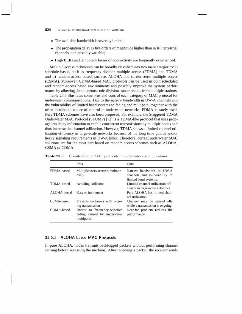
Table 23.8 illustrates some pros and cons of each category ofMAC protocol forunderwater communications. Due to the narrow bandwidth in UW-A channels andthe vulnerability of limited band systems to fading and multipath, together with theoften distributed nature of control in underwater networks, FDMA is rarely used.Pure TDMA schemes have also been proposed. For example, the Staggered TDMAUnderwater MAC Protocol (STUMP) [72] is a TDMA-like protocol that uses prop-agation delay information to enable concurrent transmissions by multiple nodes andthus increase the channel utilization. However, TDMA showsa limited channel uti-lization efficiency in large-scale networks because of the long time guards and/orheavy signaling requirements in UW-A links. Therefore, current underwater MACsolutions are for the most part based on random access schemes such as ALOHA,CSMA or CDMA.
Table 23.8 Classification of MAC protocols in underwater communications.
Pros Cons
FDMA-based Multiple users access simultane-ously
Narrow bandwidth in UW-Achannels and vulnerability oflimited band systems.
TDMA-based Avoiding collisions Limited channel utilization effi-ciency in large-scale networks.
ALOHA-based Easy to implement Pure ALOHA has limited chan-nel utilization.
CSMA-based Prevents collisions with ongo-ing transmission
Channel may be sensed idlewhile a transmission is ongoing.
CDMA-based Robust to frequency-selectivefading caused by underwatermultipaths
Near-far problem reduces theperformance.
23.5.1 ALOHA-based MAC Protocols
In pure ALOHA, nodes transmit backlogged packets without performing channelsensing before accessing the medium. After receiving a packet, the receiver sends
MEDIUM ACCESS CONTROL LAYER 825
an acknowledgment to inform the transmitter that the data has been received suc-cessfully. If a collision happens, the transmitter will notreceive the acknowledgmentand instead it will retransmit the packet. However, the efficiency of Pure ALOHA islow [70]. Slotted ALOHA is an improved version of Pure ALOHA that introducesdiscrete time slots. A node can transmit data only at the beginning of a time slot.Collisions are consequently reduced, resulting in increased throughput.
In [36], two ALOHA-based protocols, called ALOHA with collision avoidance(ALOHA-CA) and ALOHA with advance notification (ALOHA-AN),are proposedfor underwater acoustic networks. In ALOHA-CA, the sender-receiver informationextracted from the overheard packet along with the propagation delay of the packetis used to estimate for how long the channel will be busy. Based on these calcula-tions, each node decides the time for transmitting its packet to avoid collisions. Eachpacket is divided into two distinct segments, a header segment and a data segment.By overhearing a packet, each node monitors the states of every neighboring nodeand updates its local database table. A node checks its database table before trans-mitting a packet to ensure that the transmission would not result in a collision at anyother node. ALOHA-AN is an improved version of ALOHA-CA; it transmits a smalladvance NoTiFication (NTF) packet prior to transmitting the data packet so that othernodes have prior information about the data packet arrival.The sender will then waitfor a period of time, called thelag time, before sending the actual data packet. Themain advantage of having a lag time between the NTF and the data packets is thata node extracts information from multiple NTF packets and makes better decisionsin trying to avoid collisions. Small lag time prevents nodesfrom acquiring enoughNTF packets from their neighbors, thus resulting in higher collisions and as a conse-quences lower throughput. Conversely, a long lag time results in nodes wasting a lotof time listening to NFT packets, hence bandwidth is underutilized. In conclusion,with a suitable selection of the lag time, ALOHA-AN offers better throughput thanALOHA-CA.
23.5.2 CSMA-based MAC Protocols
CSMA [39] prevents collisions with ongoing transmissions at the transmitter side. Anode wishing to transmit data first listens to the medium for acertain amount of time.If it does not hear a transmission from another node, the nodeis allowed to begin itstransmission. However, due to the high propagation delay ofUW-A channels, whencarrier sense is used, the channel may be sensed idle while a transmission is ongoing,since the signal may not have reached the receiver yet. Thus,collisions are morelikely to occur.
In [94], slotted floor acquisition multiple access (SlottedFAMA) is proposed,which combines carrier sensing (CS) and a dialogue between the source and receiverprior to data transmission. During the initial dialogue, control packets are exchangedbetween the source node and the intended destination node toavoid multiple trans-missions at the same time. A node wishing to transmit data waits until the next slotand transmits an request to send (RTS) packet. The RTS packetis received by thedestination node and the neighboring nodes of the source node within the slot time.
826 ADVANCES IN UNDERWATER ACOUSTIC NETWORKING
Unlike IEEE 802.11 protocol, the destination node then sends a clear to send (CTS)packet at the beginning of the next time slot. The CTS packet will be received bythe source node and the neighboring nodes of the destinationnode within the slottime. Once the source node has received the CTS packet, it knows that it is allowedto transmit. The source node waits until the beginning of thenext slot and then startstransmitting the data packet. After the destination node has received the entire datapacket, it sends an ACK packet to indicate that the transmission has ended success-fully. Moreover, time slotting eliminates the asynchronous nature of the protocol andthe need for excessively long control packets, thus saving energy.
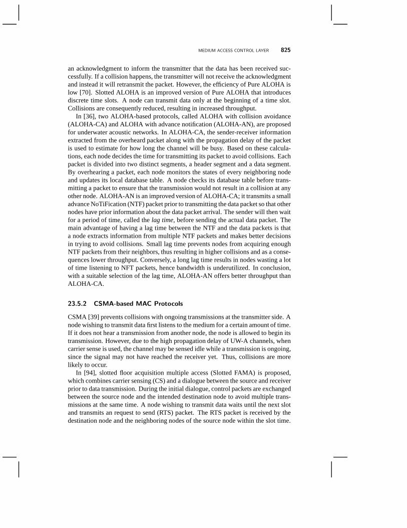
Figure 23.8 Illustration of the reservation procedure in ST-Lohi.
T-Lohi [137] is a tone-based contention mechanism that exploits space-time un-certainty and high latency to detect collisions and count contenders. Nodes sendshort reservation tones and then listen for the duration of the contention round (CR)to prevent data packet collisions. If they do not overhear tones sent by other nodes,the reservation is successful and then they transmit data atthe end of the CR. Ifmultiple nodes compete in a CR, each of them will hear the tones from other nodes,and thus will back off and try again in a later CR. T-Lohi uses alow-power wake-uptone receiver to reduce the energy consumption. The modem’sdata receiver and thehost central processing unit (CPU) are off as often as possible. They are activatedwhen a tone is detected by the low-power wake-up receiver. The authors define threeflavors of T-Lohi that vary the reservation mechanism with different implementationrequirements and performance results. Synchronized T-Lohi (ST-Lohi), as shown inFig. 23.8, assumes that all nodes are time synchronized. ST-Lohi exploits synchro-nization to estimate contender behavior, at the cost of requiring distribution of somereference time. In Conservative Unsynchronized T-Lohi (cUT-Lohi), nodes can startcontending any time they know the channel is idle. cUT-Lohi avoids the complexityof synchronization but its long contention time reduces throughput. Aggressive un-synchronized T-Lohi (aUT-Lohi) follows cUT-Lohi, howevercuts the duration of itscontention round. The channel utilization of aUT-Lohi is better than cUT-Lohi, butthe packet loss of aUT-Lohi is higher due to collisions.
A detailed comparison and performance evolution of CSMA-based protocols ispresented in [103]. The throughput efficiency and the packetlatency are compared.

MEDIUM ACCESS CONTROL LAYER 827
The performance of these protocols is evaluated from tracesrecorded during exten-sive tests off Pianosa island. The authors investigated theimpact on performance ofdifferent possible packet sizes. The results show that larger packet sizes can lead tosignificantly better system performance in terms of throughput efficiency, at a cost ofincreased packet latency, especially for low traffic loads.The authors also show howacoustic modem operations and limitations can strongly affect at-sea performanceand how overcoming some of these limitations can strongly improve the networkperformance in terms of throughput efficiency and packet latency.
23.5.3 CDMA-based MAC Protocols
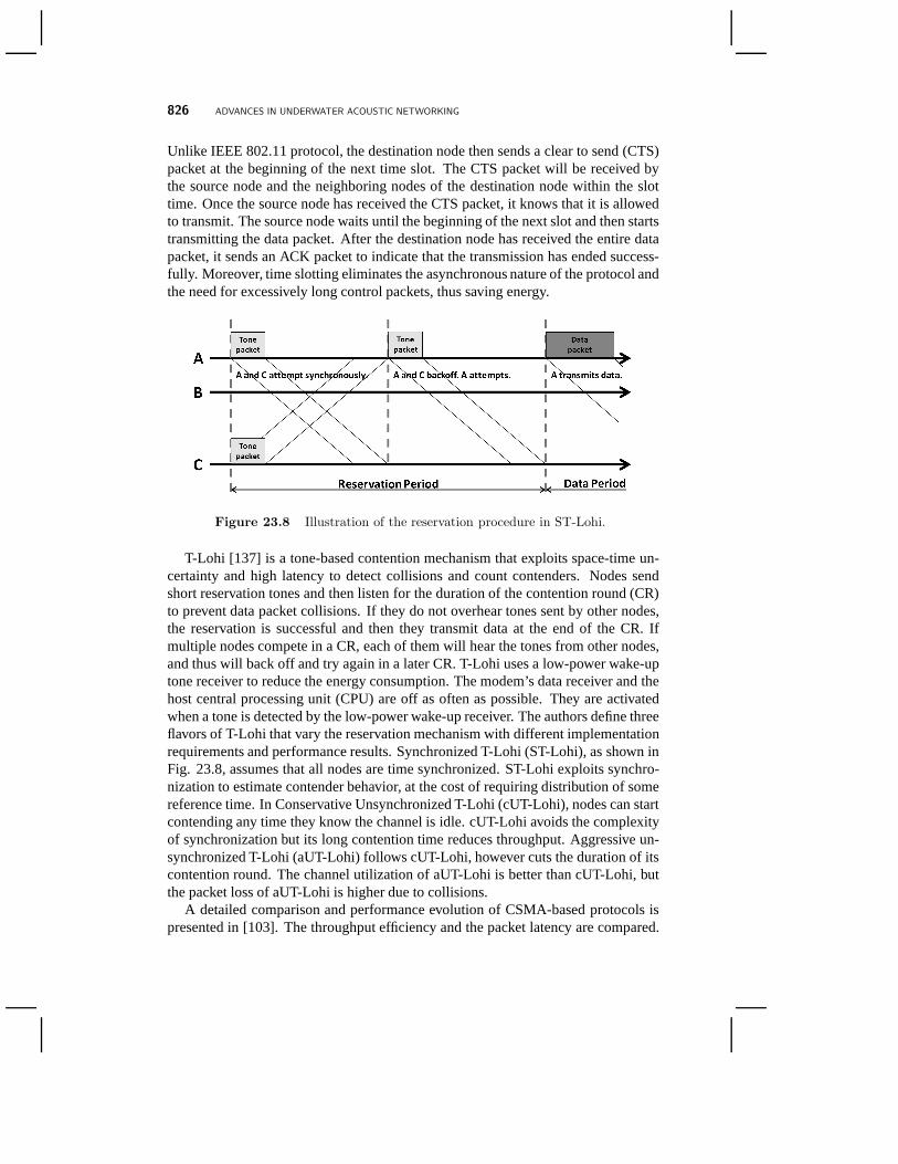
Figure 23.9 Message transmissions in UW-MAC.
CDMA transmission techniques, as discussed in Section 23.4.4, are robust tofrequency-selective fading caused by underwater multipaths. In [110], a distributedMAC protocol named UW-MAC tailored for UW-ASNs is proposed.Extensive sim-ulations demonstrate that UW-MAC achieves high network throughput, low chan-nel access delay, and low energy consumption. UW-MAC simultaneously achievesthese three objectives in deep water communications, whichusually are not severelyaffected by multipath. In shallow water communications, which may be heavilyinfluenced by multipath, it dynamically finds the optimal tradeoff among these ob-jectives according to the application requirements. UW-MAC is a transmitter-basedCDMA scheme that incorporates a novel closed-loop distributed algorithm to set theoptimal transmit power and code length.
In UW-MAC, nodes randomly access the channel transmitting ashort headercalled Extended Header (EH), which is sent using a common pseudo-random codeknown by all devices at the maximum rate (minimum code length). The EH con-tains information about the chosen next hop, and the subset of parameters that thesender will use to generate the chaotic spreading code for the actual data packet.Immediately after transmission of the EH, the sender transmits the data packet onthe channel using the optimal transmit power and code lengthset by a power andcode self-assignment algorithm. If no collision occurs during the reception of the
828 ADVANCES IN UNDERWATER ACOUSTIC NETWORKING
EH, the chosen next hop will be able to 1) synchronize to the signal from the sender,2) despread the EH using the common code, and 3) acquire the carried information.At this point, if the EH is successfully decoded, the receiver will be able to locallygenerate the chaotic code that is used by the sender to send its data packet, and setits decoder according to this chaotic code. Once the receiver has correctly receivedthe data packet from the sender, it acknowledges it by sending an ACK packet to thesender. For the distributed power and code self-assignmentproblem, UW-MAC pe-riodically collects information on the state of the channelfrom the neighborhood andfeeds the algorithm with the required information, as shownin Fig. 23.9. In orderto set the transmit power and spreading factor, a node needs to leverage informationon the multiple access interference (MAI) and normalized receiving spread signal ofneighboring nodes. This information is broadcast periodically by active nodes.
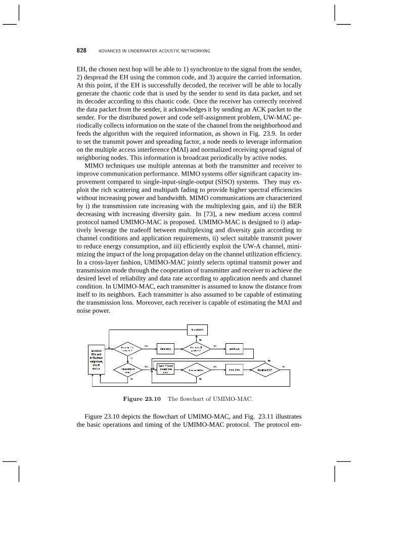
MIMO techniques use multiple antennas at both the transmitter and receiver toimprove communication performance. MIMO systems offer significant capacity im-provement compared to single-input-single-output (SISO)systems. They may ex-ploit the rich scattering and multipath fading to provide higher spectral efficiencieswithout increasing power and bandwidth. MIMO communications are characterizedby i) the transmission rate increasing with the multiplexing gain, and ii) the BERdecreasing with increasing diversity gain. In [73], a new medium access controlprotocol named UMIMO-MAC is proposed. UMIMO-MAC is designed to i) adap-tively leverage the tradeoff between multiplexing and diversity gain according tochannel conditions and application requirements, ii) select suitable transmit powerto reduce energy consumption, and iii) efficiently exploit the UW-A channel, mini-mizing the impact of the long propagation delay on the channel utilization efficiency.In a cross-layer fashion, UMIMO-MAC jointly selects optimal transmit power andtransmission mode through the cooperation of transmitter and receiver to achieve thedesired level of reliability and data rate according to application needs and channelcondition. In UMIMO-MAC, each transmitter is assumed to know the distance fromitself to its neighbors. Each transmitter is also assumed tobe capable of estimatingthe transmission loss. Moreover, each receiver is capable of estimating the MAI andnoise power.
Figure 23.10 The flowchart of UMIMO-MAC.
Figure 23.10 depicts the flowchart of UMIMO-MAC, and Fig. 23.11 illustratesthe basic operations and timing of the UMIMO-MAC protocol. The protocol em-

MEDIUM ACCESS CONTROL LAYER 829
Figure 23.11 The UMIMO-MAC protocol, where R1 is the lowest transmissionrate and R∗ is the assigned transmission rate.
ploys Intent to Send(ITS) andMode to Send(MTS) control packets to negotiateand regulate channel access among competing nodes. Note that while this may seemto be analogous to the IEEE 802.11-like carrier sense multiple access with colli-sion avoidance protocols (CSMA-CA), the analogy with CSMA-CA is limited to thetwo-way handshake - UMIMO-MAC does not employ carrier sense, and there is nocollision avoidance mechanism. In addition, unlike IEEE 802.11-like protocols, asingle ITS-MTS handshake is used to transmit a block of consecutive packets. Thisis done to improve the utilization efficiency of the underwater channel. ITS andMTS are transmitted using a common spreading code which is known by all nodes.The ITS contains i) the parameters that will be used by the transmitter to generatethe spreading code for the data packet, ii) the upper bound onthe transmit power,and iii) the total number of packets that will be transmittedback-to-back. Basedon this information, the receiver will be able to locally generate the spreading codethat the transmitter will use to send data packets. The receiver will calculate theappropriate transmission mode and transmit power for the transmitter. Besides, byoverhearing the ITS, the transmitter’s neighbors can become aware of the time whenthe transmitter will end its transmission. The MTS containsi) the chosen trans-mission mode, i.e., the multiplexing and diversity tradeoff, ii) the assigned transmitpower, iii) the receiver’s interference tolerance, and iv)the finish receive time. Thechosen transmission mode and the assigned transmit power will be used by the trans-mitter to generate the signal. However, power and transmission mode are selectedat the receiver, since the latter can be responsive to the dynamics of the channelbased on local measurements and consequently control loss recovery and rate adap-tation. With suitable transmission mode and transmit powerobtained by ITS/MTShandshake, neither the transmitter will impair nor the receiver will be impaired by
830 ADVANCES IN UNDERWATER ACOUSTIC NETWORKING
ongoing communications. Therefore, the retransmission probability is reduced, thusavoiding feedback overheads and latency. The receiver’s interference tolerance andfinish receive time are used by the neighbors of the receiver to determine their ownupper bound on transmission power. DATA and ACK are then transmitted using theassigned spreading code.
23.6 NETWORK LAYER
Because of the unique nature of the underwater environment and applications, manyexisting RF routing solutions developed for ad hoc and sensor networks show poorperformance in underwater networks. Existing routing protocols are usually dividedinto three categories, namelyproactive, reactiveandgeographicalrouting protocols:
• Proactive protocols(e.g., destination-sequenced distance vector (DSDV)[102], optimized link state routing (OLSR) [62]). These protocols attemptto minimize the message latency by maintaining up-to-date routing informa-tion at all times from each node to every other node. This is obtained bybroadcasting control packets that contain routing table information (e.g., dis-tance vectors). These protocols provoke a large signaling overhead to estab-lish routes for the first time and each time the network topology is modifiedbecause of mobility or node failures, since updated topology information hasto be propagated to all the nodes in the network. Scalabilityand excessive useof bandwidth are major issues in these families of protocols, which make themunsuitable for dynamic underwater networks.
• Reactive protocols(e.g., ad hoc on-demand distance vector (AODV) [101],dynamic source routing (DSR) [63]). A node initiates a routediscovery pro-cess only when a route to a destination is required. Once a route has beenestablished, it is maintained by a route maintenance procedure until it is nolonger desired. These protocols are more appropriate for dynamic environ-ments but incur a higher latency and still require source-initiated flooding ofcontrol packets to establish paths. Reactive protocols areconsidered unsuit-able for underwater networks because they cause a high latency in the es-tablishment of paths, which is amplified by the slow propagation of acousticsignals underwater. Furthermore, links are likely to be asymmetrical, due tobottom characteristics and variability in sound speed channel. Hence, proto-cols that rely on symmetrical links, like most reactive protocols, may not befeasible.
• Geographical routing protocols(e.g., greedy-face-greedy (GFG) [27], partial-topology knowledge forwarding (PTKF) [91]). These protocols establishsource-destination paths by leveraging localization information, i.e., each nodeselects its next hop based on the position of its neighbors and of the destina-tion node. These techniques are very promising for their scalability and lim-ited signaling requirements. However, global positioningsystem (GPS) radio
NETWORK LAYER 831
receivers do not work underwater. Therefore, ad-hoc designed accurate local-ization techniques are essential. For example, in [93], theSufficient DistanceMap Estimation (SDME) scheme provides an energy efficient self-localizationapproach for underwater mobile networks. In [138], the Underwater SensorPositioning (USP) scheme is proposed to improve localization capabilities inthree-dimensional underwater sensor networks.
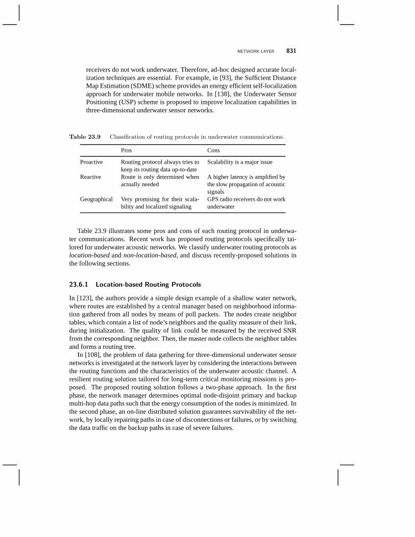
Table 23.9 Classification of routing protocols in underwater communications.
Pros Cons
Proactive Routing protocol always tries tokeep its routing data up-to-date
Scalability is a major issue
Reactive Route is only determined whenactually needed
A higher latency is amplified bythe slow propagation of acousticsignals
Geographical Very promising for their scala-bility and localized signaling
GPS radio receivers do not workunderwater
Table 23.9 illustrates some pros and cons of each routing protocol in underwa-ter communications. Recent work has proposed routing protocols specifically tai-lored for underwater acoustic networks. We classify underwater routing protocols aslocation-basedandnon-location-based, and discuss recently-proposed solutions inthe following sections.
23.6.1 Location-based Routing Protocols
In [123], the authors provide a simple design example of a shallow water network,where routes are established by a central manager based on neighborhood informa-tion gathered from all nodes by means of poll packets. The nodes create neighbortables, which contain a list of node’s neighbors and the quality measure of their link,during initialization. The quality of link could be measured by the received SNRfrom the corresponding neighbor. Then, the master node collects the neighbor tablesand forms a routing tree.
In [108], the problem of data gathering for three-dimensional underwater sensornetworks is investigated at the network layer by considering the interactions betweenthe routing functions and the characteristics of the underwater acoustic channel. Aresilient routing solution tailored for long-term critical monitoring missions is pro-posed. The proposed routing solution follows a two-phase approach. In the firstphase, the network manager determines optimal node-disjoint primary and backupmulti-hop data paths such that the energy consumption of thenodes is minimized. Inthe second phase, an on-line distributed solution guarantees survivability of the net-work, by locally repairing paths in case of disconnections or failures, or by switchingthe data traffic on the backup paths in case of severe failures.

832 ADVANCES IN UNDERWATER ACOUSTIC NETWORKING
In [112], a new geographical routing algorithms designed todistributively meetthe requirements of delay-insensitive and delay-sensitive sensor network applicationsfor the 3D underwater environment is proposed. The proposedrouting solutions al-low each node to select the optimal next hop, transmit power,and strength of theforward error correction algorithm, with the objective of minimizing the energy con-sumption. The proposed routing solution allows a node to select the next hop thatsatisfies the following two requirements: 1) it is closer to the surface station than thesender, and 2) it minimizes the energy required to successfully transmit a payloadbit from the sender to the sink. The proposed routing solutions are tailored for thecharacteristics of the 3D underwater environment, e.g., they take into account thevery high propagation delay, which may vary in horizontal and vertical links, thedifferent components of the transmission loss, the impairment of the physical chan-nel, the limited bandwidth, and the high BER. These characteristics lead to a verylow utilization of the underwater acoustic channel when communication protocolsnot specifically designed for this environment are adopted.The proposed routingsolutions allow achieving two conflicting objectives, i.e., 1) increasing the efficiencyof the acoustic channel and 2) limiting the packet error rateon each link. In otherwords, this conflict is between achieving high channel efficiency (which requireslonger packets) and maintaining low packet error rate (which requires smaller pack-ets). This problem is resolved by letting a sender transmit atrain of short packetsback-to-back without releasing the channel.
In [148], the authors propose a class of routing schemes designed to take intoaccount all major effects that characterize underwater communications and studytradeoffs in the design of energy efficient routing protocols for underwater networks.The proposed routing scheme is a geographic forwarding approach that chooses thenext hop toward the destination, and only requires local positioning information. Theoptimal per-hop distance can be calculated off-line according to different applicationrequirements, and announced to all nodes at network setup. In dynamic scenarios,one or more specific nodes are in charge of periodically calculating the optimal per-hop distance information and broadcasting it to all nodes inthe network.
In [20], the authors present a new distributed cross-layer Channel-Aware RoutingProtocol (CARP) for multi-hop delivery of data in UW-ASNs. CARP exploits linkquality information for cross-layer relay selection. Nodes are selected as relays ifthey have a history of successful transmissions to the sink through multi-hop paths.CARP combines link quality with simple topology information to find routes aroundconnectivity voids and shadow zones. CARP is also designed to take advantage ofmodem power control for selecting robust and reliable links.
23.6.2 Non-location-based Routing Protocols
In [143], a depth-based routing protocol is developed, which does not require full-dimensional location information of sensor nodes and only needs local depth infor-mation. The depth of forwarding nodes decreases while a packet is delivered to thesink if no void zone is present. In the presence of a void zone arecovery algorithm isperformed to route the packet around the void zone. A sensor node makes decisions
NETWORK LAYER 833
on packet forwarding based on its own depth and the depth of the previous sender.After receiving a packet, a node checks if it is qualified to forward the packet basedon the depth information. If the node is qualified and the packet is not in the packethistory buffer, it calculates the sending time for the packet based on the current sys-tem time and the holding time.
In [74], the authors introduce a tier-based distributed routing algorithm. The ob-jective of the proposed algorithm is to reduce the energy consumption through ade-quate selection of the next hop subject to requirements on the end-to-end packet errorrate and delay. The protocol is based on lightweight messageexchange, and the per-formance targets are achieved through the cooperation of transmitter and availablenext hops.
In particular, an analysis is conducted that shows the strong dependence of theavailable bandwidth on the transmission distance, which isa peculiar characteris-tic of the underwater environment. Two types of receivers that utilize multichannelprocessing of asynchronous multiuser signals are proposedin [132]. Both of the re-ceivers proposed offer a realistic platform for a next generation system that needs tosupport wideband acoustic CDMA communications. Other significant recent studiesconsider delay-reliability tradeoff analysis [145], the benefits achievable with coop-erative communications [30], multipath routing and pressure routing for underwatersensor networks.
In [147], a new multipath power-control transmission (MPT)scheme is proposedto guarantee certain end-to-end packet error rate while achieving a good balancebetween the overall energy efficiency and the end-to-end packet delay. MPT com-bines power control with multipath routing and packet combining at the destina-tion. Through the proposed power-control strategies, MPT consumes less energythan the conventional one-path transmission scheme without retransmission. More-over, MPT, for which retransmissions are not allowed, introduces shorter delays thanthe traditional one-path scheme with retransmission. MPT assumes that underwa-ter sensor nodes with acoustic modems are densely distributed in a 3D underwaterenvironment, and multiple gateway nodes with both acousticand RF modems aredeployed on the water surface. Each underwater sensor node monitors local eventsand reports the data to one or multiple surface gateway nodesthrough acoustic links,and the surface gateway nodes transmit the data to the destination through the RFmodem. MPT can be divided into multipath routing, source initiated power-controltransmission, and destination packet combining. First, the source node initiates amultipath routing process to find paths from the source to thesurface gateway nodes.Through this routing process, the source node selects some paths and calculates theoptimal transmit power for each node along the selected paths. Then, the source nodesends the same packet along the selected paths. The relay nodes on these selectedpaths will read the packet header and obtain the specified transmit power parametersfor relaying the packet. Finally, the destination receivesall copies of the packet andperforms packet combining to recover the original packet.
In [77], a hydraulic pressure based anycast routing protocol named HydroCast isproposed to report time-critical sensor data to the sonobuoys on the ocean surfaceusing acoustic multi-hopping. The major challenges in thiswork are the ocean cur-
834 ADVANCES IN UNDERWATER ACOUSTIC NETWORKING
rent and the limited bandwidth and energy in underwater acoustic communications.HydroCast is a 2D geographic route discovery method in a vertical direction to theocean surface using the depth information from a pressure sensor. The path is froma mobile sensor to any one of the sonobuoys on the ocean surface. The tagging ofthe sensed data with its location can be performed when the data come to the sur-face monitoring center, and the off-line localization method is performed by localneighbor information collected from each node. An efficientrecovery method withdelivery guarantee is used in HydroCast to recover from a dead end. Instead of usingexpensive 3D flooding, the authors present a local lower-depth-first recovery methodthat guarantees the delivery using 2D surface flooding. The number of packet trans-missions in underwater sensor deployments challenged by ocean currents, unreliableacoustic channels and voids is reduced.
The Void Aware Pressure Routing (VAPR) protocol [96] sets upthe next hop di-rection with periodic beacons, which include sequence number, hop count and depthinformation. A directional trail to the closest sonobuoy isbuilt, and the opportunisticdirectional forwarding can be efficiently performed even inthe presence of voids. Atthe beginning, sonobuoys broadcast their reachability information to sensor nodesvia periodic beacons. Each node updates the received beaconvariables includingminimal hop to the surface, sequence number, data forwarding direction, and nexthop data forwarding direction. Then, the updated beacon is broadcasted to neigh-bors. After receiving multiple beacon messages from different nodes, a node choosesthe node with minimal hop count as the next hop.
23.7 CROSS-LAYER DESIGN
In a traditional layered architecture, each layer interacts only with the adjacent lay-ers in the protocol stack through well-defined interfaces. Although strictly layeredarchitectures have served well the development of wired networks, they are knownto be less than ideally suited for energy constrained wireless applications includingUW-ASNs. While a layered architecture may achieve high performance in terms ofmetrics associated with each individual layer, it does not allow joint optimizationof functionalities at different layers of the protocol to maximize the overall networkthroughput or minimize the energy consumption [92]. Cross-layer design breaksthe barrier of rigid interaction only among neighboring layers, by allowing interac-tions among different layers that may lead to higher networkefficiency and flexibleQuality of Service (QoS) support. The highly dynamic natureof underwater acous-tic channel calls for cross-layer design for efficient data delivery. Since underwateracoustic networks are power constrained and as routing and medium access deci-sions have strong impact on power consumption, joint decisions of both may lead tomore efficient power usage for UW-ASNs.
In [65], the proposed Focused Beam Routing (FBR) protocol, based on loca-tion information, considers energy-efficient multi-hop communications in underwa-ter acoustic networks. Data packets are routed with minimumenergy in a cone-shaped region whose axis passes through the sender and the receiver. The transmis-
CROSS-LAYER DESIGN 835
sion power is increased until an intermediate relay node is found. By coupling rout-ing and MAC functionalities with power control, the next relay is selected at eachstep of the path. The proposed FBR protocol is suitable for underwater networkscontaining both static and mobile nodes.
In [106], the authors explore cross-layer design techniques to make efficient useof the bandwidth-limited acoustic channel. The objective of their work is: 1) studythe interactions of key underwater communication functionalities such as modu-lation, forward error correction, medium access control, and routing; and 2) de-velop a distributed cross-layer communication solution that allows multiple devicesto efficiently and fairly share the bandwidth-limited high-delay underwater acous-tic medium. The authors develop a resource allocation framework that accuratelymodels every aspect of the layered network architecture. Efficient underwater com-munication is achieved by a distributed optimization problem to jointly control therouting, MAC, and physical functionalities. The proposed solution combines a 3Dgeographical routing algorithm (routing functionality),a novel hybrid distributedCDMA/ALOHA-based scheme to access the bandwidth-limited high-delay sharedacoustic medium (MAC functionality), and an optimized solution for the joint selec-tion of modulation, FEC, and transmit power (physical functionalities). The authorsgroup underwater multimedia applications into four trafficclasses and highlight theirdifferent requirements. The authors integrate the CDMA/ALOHA-based MAC andlocation-based routing functionalities and control different communication function-alities in a distributed manner.
Multimedia underwater sensor networks would enable new applications for un-derwater multimedia surveillance, undersea explorations, video-assisted navigationand environmental monitoring. However, these applications require much higherdata rates than currently available with acoustic technology, and more flexible pro-tocol design to accommodate heterogeneous traffic demands in terms of bandwidth,delay, and end-to-end reliability. To accommodate such traffic demands, UMIMO-Routing [75] is proposed to leverage the potential of MIMO transmission techniqueson acoustic links, leverage the potential of OFDM to reduce inter-carrier interfer-ence, and develop a new cross-layer routing protocol to flexibly exploit the potentialperformance increase offered by MIMO-OFDM links under the unique challengesposed by the underwater environment. For these reasons, theobjective of UMIMO-Routing is to explore the capabilities of underwater MIMO-OFDM links, and toleverage these from the perspective of higher layer protocols, and in particular at therouting layer, with a cross-layer design approach.
UMIMO-Routing considers multimedia underwater monitoring applications withheterogeneous traffic demands in terms of bandwidth and end-to-end reliability. Dis-tributed routing algorithms are introduced for delay-insensitive and delay-sensitiveapplications, with the objective of reducing the energy consumption by i) leverag-ing the tradeoff between multiplexing and diversity gain that characterizes MIMOlinks, and ii) allocating transmit power on suitable subcarriers according to channelconditions and application requirements. To achieve the above objective, each nodejointly i) selects the next hop, ii) chooses a suitable transmission mode, and iii) as-

836 ADVANCES IN UNDERWATER ACOUSTIC NETWORKING
signs optimal transmit power on different subcarriers to achieve a target level of QoSin a cross-layer fashion.
23.8 EXPERIMENTAL PLATFORMS
In addition to simulation studies, extensive field experimentation is needed to vali-date underwater transmission schemes and networking protocols. Unfortunately, set-ting up an experimental platform for underwater acoustic networks is very expensivecompared to establishing an RF wireless sensor network testbed. Not only are acous-tic modems expensive, but also the deployment and maintenance of the testbed itselfare costly. As a natural consequence, deployment of underwater acoustic sensorsin general are less dense, fewer sensors are utilized and with longer communicationrange compared to deployments in terrestrial wireless sensor networks [57]. A lim-ited number of experimental platforms have been deployed sofar. In Section 23.8.1we discuss some of the available commercial acoustic modems, while in Section23.8.2 we discuss some of the available experimental acoustic modems. Finally, inSection 23.8.3 we review recent progress in developing underwater acoustic testbeds.
23.8.1 Commercial Acoustic Modems
There are only a handful of companies involved in manufacturing of commercialacoustic modems. Some of the leading companies include Teledyne Benthos,LinkQuest, EvoLogics, DSPComm and Tritech; as well as a few platforms devel-oped within the research community, most notably the WHOI Micro-Modem. In thefollowing section, we review the state-of-the-art in commercial acoustic modemsin terms of modulation schemes, transmission capacity, power efficiency, operatingdepth and range, and networking capabilities.
Teledyne Benthos. Teledyne Benthos [5] is a leading manufacturer of under-water acoustic modems located in the United States. Benthosoffers a wide varietyof underwater acoustic equipments; ranging from acoustic modems, acousticreleases and Smart Modem Acoustic Release Technology (SMART) products.We focus on some of their acoustic modems including ATM-900 series, SMARTmodems and surface unit UDB-9000. ATM-900 series acoustic telemetry modemsprovide high data capacity logging capability through datastorage and usercommand line interfaces to real-time clock integration. The SMART modemseries provides release functionalities and enables real-time communication withsubsea devices. The SM-75 product in the line of SMART modem series is anall-in-one design that provides float and release capabilities. The RS-232 serialinterface enables modem connection to an attached sensors.The Universal DeckBox, UDB-9000 is a multi-receive deck box that operates withTeledyne Benthosacoustic modems and releases. The acoustic data modulationmethods provided bythe modems are PSK and MFSK. Table 23.10 summarizes some of the importantcharacteristics of both conventional and SMART acoustic modems provided by

EXPERIMENTAL PLATFORMS 837
Teledyne Benthos. In addition, Teledyne Benthos modems mayallow playing andrecording an arbitrary waveform, and provide substantial support for networkedoperations - see also discussion in Section 23.9.
Table 23.10 A selection of commercial acoustic modems offered by TeledyneBenthos [5].
Product Depth [m] Data Rate [bit/s] Range [km] BER
ATM-920 2000 140 - 15, 360 2 - 6 < 10−7
ATM-960 6000 140 - 15, 360 2 - 6 < 10−7
SR-100 6700 140 - 15, 360 max.10 < 10−7
SR-50 305 140 - 15, 360 max.10 < 10−7
SM-75 6700 140 - 15, 360 max.10 < 10−7
LinkQuest. LinkQuest Inc. [3] is another manufacturer of precision acoustic instru-ments including underwater acoustic modems and tracking systems. LinkQuest pro-duces a number of acoustic modems ranging from short range, low power modems(UWM 1000) for shallow water communications to long range, high power modems(UWM 10000) for deep ocean communications. Each of their acoustic modems istailored for a specific application. Data rates vary depending on the range of com-munication and power mode. LinkQuest acoustic modems may beused for near-vertical, horizontal and extreme horizontal underwater environments. In addition,the acoustic modems are equipped with RS-232 connections that may be used toconnect to underwater sensors. Table 23.11 summarizes someof the acoustic prod-ucts characteristics provided by LinkQuest.
Table 23.11 A selection of commercial acoustic modems offered byLinkQuest [3].
Product Depth [m] Data Rate [bit/s] Range [km] BER
UWM 1000 2000 960 - 19200 0.35 < 10−9
UWM 2000 2000/4000 1960 - 19200 1.2/1.5 < 10−9
UWM 3000 2000/4000/7000 2500 - 5000 3/5 < 10−9
UWM 4000 3000/7000 4800 - 9600 3/6 < 10−9
UWM 10000 2000/4000/7000 2500 - 5000 7/10 < 10−9
EvoLogics. EvoLogics [6] is a manufacturer of underwater modems based in Ger-many. EvoLogics provides advanced underwater acoustic solutions including un-derwater acoustic modems, sonobots, subsea gliders and bionik robotics. We focuson the underwater acoustic modems. The R-series are software-configurable un-derwater acoustic modems that offer full-duplex acoustic transmission utilizing S2C(Sweep-Spread Carrier) scheme. The R-series modems provide solutions for short-
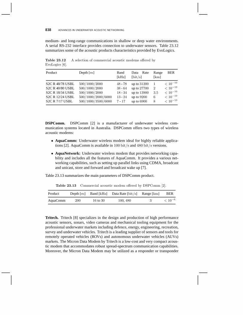
838 ADVANCES IN UNDERWATER ACOUSTIC NETWORKING
medium- and long-range communications in shallow or deep water environments.A serial RS-232 interface provides connection to underwater sensors. Table 23.12summarizes some of the acoustic products characteristics provided by EvoLogics.
Table 23.12 A selection of commercial acoustic modems offered byEvoLogics [6].
Product Depth [m] Band[kHz]
Data Rate[bit/s]
Range[km]
BER
S2C R 48/78 USBL 500/1000/2000 48 - 78 up to31200 1 < 10−10
S2C R 40/80 USBL 500/1000/2000 38 - 64 up to27700 2 < 10−10
S2C R 18/34 USBL 500/1000/2000 18 - 34 up to13900 3.5 < 10−10
S2C R 12/24 USBL 500/1000/2000/6000 13 - 24 up to9200 6 < 10−10
S2C R 7/17 USBL 500/1000/3500/6000 7 - 17 up to6900 8 < 10−10
DSPComm. DSPComm [2] is a manufacturer of underwater wireless com-munication systems located in Australia. DSPComm offers two types of wirelessacoustic modems:
• AquaComm: Underwater wireless modem ideal for highly reliable applica-tions [2]. AquaComm is available in100 bit/s and480 bit/s versions.
• AquaNetwork: Underwater wireless modem that provides networking capa-bility and includes all the features of AquaComm. It provides a various net-working capabilities, such as setting up parallel links using CDMA, broadcastand unicast, store and forward and broadcast wake up [7].
Table 23.13 summarizes the main parameters of DSPComm product.
Table 23.13 Commercial acoustic modem offered by DSPComm [2].
Product Depth [m] Band [kHz] Data Rate [bit/s] Range [km] BER
AquaComm 200 16 to 30 100, 480 3 < 10−6
Tritech. Tritech [8] specializes in the design and production of highperformanceacoustic sensors, sonars, video cameras and mechanical tooling equipment for theprofessional underwater markets including defence, energy, engineering, recreation,survey and underwater vehicles. Tritech is a leading supplier of sensors and tools forremotely operated vehicles (ROVs) and autonomous underwater vehicles (AUVs)markets. The Micron Data Modem by Tritech is a low-cost and very compact acous-tic modem that accommodates robust spread-spectrum communication capabilities.Moreover, the Micron Data Modem may be utilized as a responder or transponder
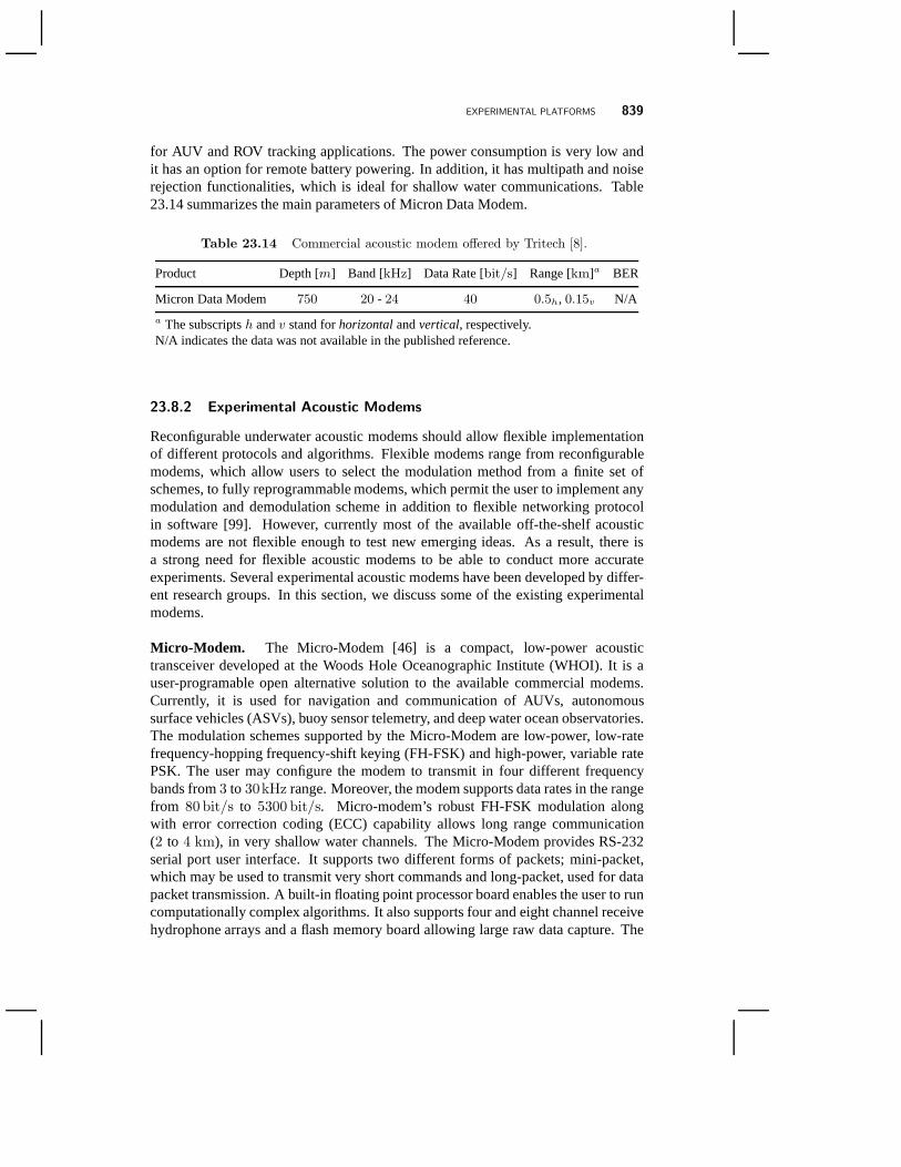
EXPERIMENTAL PLATFORMS 839
for AUV and ROV tracking applications. The power consumption is very low andit has an option for remote battery powering. In addition, ithas multipath and noiserejection functionalities, which is ideal for shallow water communications. Table23.14 summarizes the main parameters of Micron Data Modem.
Table 23.14 Commercial acoustic modem offered by Tritech [8].
Product Depth [m] Band [kHz] Data Rate [bit/s] Range [km]a BER
Micron Data Modem 750 20 - 24 40 0.5h, 0.15v N/A
a The subscriptsh andv stand forhorizontalandvertical, respectively.N/A indicates the data was not available in the published reference.
23.8.2 Experimental Acoustic Modems
Reconfigurable underwater acoustic modems should allow flexible implementationof different protocols and algorithms. Flexible modems range from reconfigurablemodems, which allow users to select the modulation method from a finite set ofschemes, to fully reprogrammable modems, which permit the user to implement anymodulation and demodulation scheme in addition to flexible networking protocolin software [99]. However, currently most of the available off-the-shelf acousticmodems are not flexible enough to test new emerging ideas. As aresult, there isa strong need for flexible acoustic modems to be able to conduct more accurateexperiments. Several experimental acoustic modems have been developed by differ-ent research groups. In this section, we discuss some of the existing experimentalmodems.
Micro-Modem. The Micro-Modem [46] is a compact, low-power acoustictransceiver developed at the Woods Hole Oceanographic Institute (WHOI). It is auser-programable open alternative solution to the available commercial modems.Currently, it is used for navigation and communication of AUVs, autonomoussurface vehicles (ASVs), buoy sensor telemetry, and deep water ocean observatories.The modulation schemes supported by the Micro-Modem are low-power, low-ratefrequency-hopping frequency-shift keying (FH-FSK) and high-power, variable ratePSK. The user may configure the modem to transmit in four different frequencybands from3 to 30kHz range. Moreover, the modem supports data rates in the rangefrom 80 bit/s to 5300 bit/s. Micro-modem’s robust FH-FSK modulation alongwith error correction coding (ECC) capability allows long range communication(2 to 4 km), in very shallow water channels. The Micro-Modem providesRS-232serial port user interface. It supports two different formsof packets; mini-packet,which may be used to transmit very short commands and long-packet, used for datapacket transmission. A built-in floating point processor board enables the user to runcomputationally complex algorithms. It also supports fourand eight channel receivehydrophone arrays and a flash memory board allowing large rawdata capture. The

840 ADVANCES IN UNDERWATER ACOUSTIC NETWORKING
power consumption of the Micro-Modem is very low. Moreover,it includes somebasic built-in networking capabilities, which supports upto 16 units in a polled orrandom-access mode and its acknowledgement scheme may be used to guaranteesuccessful packet delivery.
rModem. rModem [122] is a reconfigurable acoustic modem developed atthe Massachusetts Institute of Technology (MIT). rModem isdesigned to allowthe user to reconfigure functionalities across different layers of protocol stack withpossibility of cross-layer optimization. It contains a digital signal processor, (DSP)and a field-programmable gate array (FPGA). The FPGA allows the user to operateat any carrier frequency and bandwidth within the1kHz to 100kHz range, while theDSP running at255 MHz enables floating point arithmetic computation. Moreover,it has32 Mbytes of internal flash RAM for persistent program and data storageand32 Mbytes of SD-RAM for program and memory storage. rModem allows MIMOtransmission schemes to be implemented using the four configurable input andoutput channels. The embedded analog anti-aliasing filter with 1 kHz to 100 kHzbandwidth may be used for various applications while the56 pin daughter cardport accommodates future expansions. rModem provides a graphical user interface(GUI), which may be used to control the rModem’s hardware, send and receivepackets, and log events and data.
UANT Platform. The Underwater Acoustic Networking plaTform (UANT)[140] is a software-defined research platform designed at the University of Califor-nia, Los Angeles (UCLA). The objective is to provide a flexible software-definedreconfigurable platform for researchers to experiment new protocols and modulationschemes on a fully functional underwater network. UANT usesGNU Radio, asoftware-defined framework, for physical layer design configurations and TinyOSfor network protocol stack design. UANT allows real time configuration of theacoustic modem. Hence, it may adapt to constantly changing underwater acousticenvironment. UANT provides a Gaussian Minimum Shift Keying(GMSK) mod-ulation scheme and allows data rate configuration from244 bit/s to 500 kbit/s,while the central frequency may be varied from0.1 Hz to 30 MHz. UANT maybe reconfigured at the physical, MAC, and application layers. However, one of thedrawbacks of UANT platform is that it needs to run on a personal computer.
SWDAM Project. UW SWDAM [54] is a Software Defined Acoustic Mo-dem project developed at the University of Washington. The general idea is to getthe software as close to the antennas as possible so that researchers can implementthe entire modem stack in software using general purpose processors. To achievethis, an Intel D945GCLF2 mini-ITX motherboard and an Avnet Memec’s Spartan-II200 PCI development kit board in cooperation with Avnet Memec’s P160 AnalogModule daughter-board are utilized. A linear amplifier and aprojector are usedfor the transmitter, and a hydrophone and a preamplifier are used for the receiver.Moreover, common operating systems such as Linux or Microsoft Windows can be
EXPERIMENTAL PLATFORMS 841
implemented on the ITX platforms, which enables researchers to port algorithmsfrom their desktops.
23.8.3 Experimental Testbeds
Building real experimental systems and conducting actual experiments in underseais very expensive. Although simulations may be considered as an alternativesolution, it is very difficult to accurately model the underwater acoustic channel.Consequently, simulations may lead to inaccurate results.An intermediate solutionthat overcomes the limitations of simulations is using experimental testbeds toadequately evaluate algorithms and protocols in real-world scenarios. In this sectionwe present some of the existing experimental testbed platforms as well as ongoingprojects.
Seaweb Project. Seaweb [116] is among the first experimental platforms pri-marily designed for military applications. Seaweb is funded by Office of NavalResearch (ONR) and it is run by Spawar Systems Center (SSC) San Diego and NavalPostgraduate School (NPS) with Teledyne Benthos as the maincontractor. Seawebis a wide-area network with DSP-based telesonar underwateracoustic modems thatconnects autonomous and fixed nodes together. Backbone nodes are autonomous,stationary sensors and telesonar repeaters. Peripheral nodes include unmannedundersea vehicles (UUVs) and specialized devices such as low-frequency sonarprojectors. Gateway nodes provide interfaces with commandcenters afloat, sub-merged, ashore, and aloft, including access to terrestrial, airborne, and space-basednetworks. Seaweb is an organized network for command, control, communica-tions, and navigation (C3N ) of deployable autonomous undersea systems [116].Throughout the years many networking protocols have been developed and usingSeaweb platform numerous field tests have been carried out tovalidate the protocols.
CMRE NATO Facility. The Centre for Maritime Research and experimenta-tion (CMRE) [9], formerly known as the NATO Undersea Research Centre (NURC)[113, 115, 23] is a scientific research and experimentation NATO facility. Amongother research areas, CMRE is engaged in conducting research on off-board LowFrequency Active (LFA) sensors that could be used in Cooperative distributedAnti-Submarine Warfare (CASW) [23] to create a scalable andautonomous systemthat would potentially remove vulnerable personnel from high risk areas such asdeep oceans. Moreover, CMRE is involved in standardizing channel modelingschemes and networking architecture design that supports cross-layer interactions[113]. CMRE also runs and maintains an underwater networking testbed withheterogeneous modems [24].
Ocean-TUNE Testbed. A community Ocean Testbed for Underwater Net-works Experiments (Ocean-TUNE) is presented in [40]. Ocean-TUNE is acollaborative work from four institutions namely, University of Connecticut,University of Washington, University of California, Los Angeles, and Texas A&M
842 ADVANCES IN UNDERWATER ACOUSTIC NETWORKING
University. Ocean-TUNE is an open testbed suite comprised of four testbedsremotely accessible to the public at four different sites that will enable advancementof research in the areas of underwater communications, networking, engineering,and marine science communities. The testbeds provide flexible choices of surfacenodes, bottom nodes, and mobile nodes (gliders and drifters). Three of the testbedsinclude reconfigurable modems with MIMO capabilities that may allow the user toexperiment various acoustic communication strategies. The network nodes in eachtestbed are equipped with OFDM acoustic modems that could provide high datarates and strong networking support.
SUNSET Framework. The Sapienza University Networking framework forunderwater Simulation Emulation and real-life Testing (SUNSET), developed bythe UWSN Group [10], is a collaborative effort between the WHOI, the NATOUndersea Research Centre (NURC) and the University of “Sapienza”. SUNSETprovides a framework based on open source network simulatorns-2 [11] software,for simulating and testing at sea underwater acoustic communication protocols.The framework contains a number of commercial acoustic modems models thatallows simulation and emulation of actual underwater acoustic channel conditions.Moreover, the simulator code written in ns-2 may be ported onto a small computer-on-module hardware device like Gumstix [12], which may be embedded inside anacoustic modem or AUV’s housing to control their functionalities. In addition to thatthe framework allows interfacing software communication modules with varioushardware and commercial acoustic modems, and at the same time having an openarchitecture to allow integration with different acousticmodems and AUV’s. Theframework is a powerful tool that may be used to validate, test and implement newalgorithms and protocols [104].
DESERT Underwater. DESERT Underwater is an NS-Miracle based frame-work to DEsign, Simulate, Emulate and Realize Test-beds forUnderwater networkprotocols [89] developed at the University of Padova. The objective of this frame-work is to realize a complete set of public C/C++ libraries tosupport the design andimplementation of underwater network protocols. DESERT Underwater extends theNS-Miracle [13] simulation software library, an ns2-basedsimulation platform alsodeveloped at the University of Padova, to accommodate a number of protocol stacksfor underwater networks, and to support routines essentialfor the development ofnew protocols.
WHOI UAN Testbed. The WHOI is developing an underwater acoustic network(UAN) testbed [44], which will provide a valuable infrastructure for evaluating anddeveloping network protocols for shallow and deep water communications. Thetestbed can be made available for collaborative experiments with the UAN researchcommunity. The acoustic nodes in the testbed can remotely becontrolled throughthe serial port over the Internet for most of the experimental configurations. Eachtestbed node includes a WHOI Micro-Modem, which is controlled by a Gumstix,an embedded computer, on which network protocols are implemented and executed.
UW-BUFFALO: AN UNDERWATER ACOUSTIC TESTBED AT THE UNIVERSITY AT BUFFALO 843
The center frequency of the transducer is25 kHz with 5 kHz bandwidth and the datarates range from80 bit/s to 5300 bit/s. Moreover, the testbed includes buoy nodesthat operate at both10 kHz and25 kHz, and are equipped with GPS receivers andFreewave radios to provide gateway routing capabilities.
CPS Lab Project. The Cyber Physical Systems (CPS) Laboratory [14] atRutgers University is developing an acoustic communication substrate to supportcross-layer underwater communication strategies for AUV inter-communicationswhile supporting traffic with different QoS requirements. Ademonstration ofunderwater vehicle team formation and steering algorithmsusing CPS underwatertestbed are described in [35]. The testbed allows the user toconfigure ocean currentsand underwater communication parameters through a GUI. With a multi-inputmulti-output audio interface installed on a Personal Computer (PC), the user canadjust the signal gains, introduce propagation delay, mix the acoustic signals, andadd ambient and man-made noise as well as interference in real time.
23.9 UW-BUFFALO: AN UNDERWATER ACOUSTIC TESTBED AT
THE UNIVERSITY AT BUFFALO
The underwater acoustic networking testbed at the University at Buffalo (UW-Buffalo) [15] is designed to bridge the gap between experimentation and theoreticaldevelopments in underwater communications and networking, and is the result of ajoint venture between the University at Buffalo and Teledyne Benthos. The objectiveof the project is to provide the research community with a versatile and shared recon-figurable platform to enable experimental evaluation of underwater communicationsand networking protocols.
The testbed, which is being developed under sponsorship of the US National Sci-ence Foundation, is based on the Teledyne Benthos TelesonarSM-75 modem, which,in its many configurations, is also a key component in multiple U.S. Navy programsand of many wireless tsunami warning systems worldwide.
In the commercial implementation of the SM-75 Benthos modem, all networkingfunctionalities, including channel access negotiation, selective repeat request (SRQ),and waveform selection, reside within the core DSP of the individual modem, andcannot be reconfigured by the end-user. Similarly, the existing network layer im-plements static routing tables at each node in the network within the main modemboard, and is not separable from it. Therefore, in the current on-board networkingimplementation, all packet processing occurs completely within the modem CPU andfirmware. This does not allow for external implementation ofalternate networkingand MAC schemes, and this logic is only accessible by Teledyne Benthos personnel.
The SM-75 has been modified to allow the research community toperformadvanced networking and communication experiments as follows. First, a pro-grammable Gumstix network processor is being interfaced with the SM-75 modem

844 ADVANCES IN UNDERWATER ACOUSTIC NETWORKING
through a newly designed interface that defines communication primitives betweenthe modem board and the external processor. A reconfigurable, software-definedprotocol stack, including medium access control, IP network layer with reconfig-urable ad hoc routing, network self-configuration primitives (e.g., neighbor discov-ery, DHCP), is being implemented on the Gumstix board to enable the definitionof complex networking experiments with reconfigurable, cross-layer designed pro-tocol stacks. Second, the modified platform allows playing and recording customdefined acoustic waveforms to allow reconfigurable physical-layer experimentationwith arbitrary transmission schemes. The testbed architecture is modeled after thearchitecture illustrated in Fig. 1.1. The modems are based on SM-75 with embeddedGumstix inside the housing, while the surface station is based on UDB-9000 (alsofrom Teledyne Benthos).
23.10 CONCLUSIONS
In this chapter, we provided a comprehensive account of recent advances in underwa-ter acoustic communications and networking. We described the typical communica-tion architecture of an underwater network. We discussed key notions of underwateracoustic propagation and the state of the art in acoustic communication techniques atthe physical layer. We described the challenges posed by thepeculiarities of the un-derwater channel with particular reference to monitoring applications for the oceanenvironment. We presented an overview of the recent advances in protocol design atthe medium access control and network layers in addition to cross-layer design. Fi-nally, we provided a detailed discussion of the existing underwater acoustic platformsfor experimental evaluation of underwater networks. The objective of this chapter isto encourage research efforts to lay down fundamental basisfor the development ofnew advanced communication techniques for efficient underwater communicationand networking for enhanced ocean monitoring and exploration applications.
Acknowledgements
This chapter is based on material supported by the US National Science Foundationunder grants CNS-1055945 and CNS-1126357.
REFERENCES
1. AQUAmodem Technology Overview. [Online]. Available:http://www.aquatecgroup.com.
2. DSPComm, AquaComm: Underwater wireless modem. [Online]. Available:http://www.dspcomm.com.
3. LinkQuest, Underwater Acoustic Modem Models. [Online].Available: http://www.link-quest.com.
4.
5. Teledyne-Benthos, Acoustic Modems. [Online]. Available: http://www.benthos.com.
6. EvoLogics, Underwater Acoustic Modems. [Online]. Available:http://www.evologics.de.
7. DSPComm, AquaNetwork: Underwater wireless modem with networking capability.[Online]. Available: http://www.dspcomm.com.
8. Tritech, Micron Data Modem. [Online]. Available: http://www.tritech.co.uk.
9. NATO S&T Organization: Centre for Maritime Research and Experimentation. [On-line]. Available: http://www.cmre.nato.int/.
10. SUNSET: Sapienza University Networking framework for underwa-ter Simulation, Emulation and real-life Testing. [Online]. Available:http://reti.dsi.uniroma1.it/UWSNGroup/.
11. The VINT Project, The Network Simulator Manual. [Online]. Available:http://www.isi.edu/nsnam/ns/.
Mobile Ad Hoc Networking: Cutting Edge Directions, Second Edition. Edited by Stefano Basagni,Marco Conti, Silvia Giordano and Ivan Stojmenovicc© 2013 by The Institute of Electrical and Electronics Engineers. Published 2013 by John Wiley & Sons, Inc.
845
846 REFERENCES
12. Gumstix Inc. [Online]. Available: http://www.gumstix.com.
13. The Network Simulator - NS-Miracle. [Online]. Available:http://telecom.dei.unipd.it/pages/read/58/.
14. Communication and Coordination among Autonomous Underwater Vehicles. [Online].Available: http://nsfcac.rutgers.edu/CPS/.
15. T. Melodia, S. Batalama, D. Pados, W. Su, J. Atkinson. UW-Buffalo: AnUnderwater Acoustic Testbed at the University at Buffalo. [Online]. Available:http://www.eng.buffalo.edu/wnesl/underwatertestbed.html.
16. I. F. Akyildiz, T. Melodia, and K. R. Chowdhury. A Survey on Wireless MultimediaSensor Networks.Computer Networks (Elsevier), 51(4):921–960, March 2007.
17. I. F. Akyildiz, D. Pompili, and T. Melodia. Challenges for Efficient Communication inUnderwater Acoustic Sensor Networks.ACM SIGBED Review, 1(2), July 2004.
18. I. F. Akyildiz, D. Pompili, and T. Melodia. Underwater Acoustic Sensor Networks:Research Challenges.Ad Hoc Networks (Elsevier), 3(3):257–279, May 2005.
19. S. A. Aliesawi, C. C. Tsimenidis, B. S. Sharif, and M. Johnston. Iterative MultiuserDetection for Underwater Acoustic Channels.IEEE Journal of Oceanic Engineering,36(4):728–744, October 2011.
20. S. Basagni, C. Petrioli, R. Petroccia, and D. Spaccini. Channel-aware Routing for Un-derwater Wireless Networks. InProc. of MTS/IEEE OCEANS 2012, pages 1–9, Yeosu,South Korea, May 2012.
21. S. Basagni, C. Petrioli, R. Petroccia, and M. Stojanovic. Optimizing Network Perfor-mance through Packet Fragmentation in Multi-hop Underwater Communications. InProc. of MTS/IEEE OCEANS 2010, pages 1–7, Sydney, Australia, May 2010.
22. S. Basagni, C. Petrioli, R. Petroccia, and M. Stojanovic. Optimized packet size se-lection in underwater WSN communications.IEEE Journal of Oceanic Engineering,37(3):321–337, 2012.
23. R. Been, D. T. Hughes, J. R. Potter, and C. Strode. Cooperative anti-submarine warfareat NURC moving towards a net-centric capability. InProc. of MTS/IEEE OCEANS2010, pages 1–10, Sydney, Australia, May 2010.
24. R. Been, D. T. Hughes, and A. Vermeij. Heterogeneous underwater networks for ASW:technology and techniques. InProc. of Underwater Defence Technology (UDT), Glas-gow, UK, June 2008.
25. C. R. Berger, S. Zhou, J. C. Preisig, and P. Willett. Sparse channel estimation for mul-ticarrier underwater acoustic communication: From subspace methods to compressedsensing. InProc. of MTS/IEEE OCEANS 2009, pages 1–8, Bremen, Germany, May2009.
26. F. Blackmon, E. Sozer, and J. Proakis. Iterative equalization, decoding, and soft diversitycombining for underwater acoustic channels. InProc. of MTS/IEEE OCEANS 2002,volume 4, pages 2425–2428, October 2002.
27. P. Bose, P. Morin, I. Stojmenovic, and J. Urrutia. Routing with Guaranteed Delivery inAd Hoc Wireless Networks.ACM Wireless Networks, 7(6):609–616, November 2001.
28. E. Calvo and M. Stojanovic. Efficient channel-estimation-based multiuser detection forunderwater CDMA systems.IEEE Journal of Oceanic Engineering, 33(4):502–512,October 2008.
REFERENCES 847
29. V. Capellano. Performance improvements of a 50 km acoustic transmission throughadaptive equalization and spatial diversity. InProc. of MTS/IEEE OCEANS 1997, vol-ume 1, page 569573, Halifax, Nova Scotia, Canada, 1997.
30. C. Carbonelli, S.-H. Chen, and U. Mitra. Error Propagation Analysis for Underwa-ter Cooperative Multihop Communications.Journal on Ad Hoc Networks (Elsevier),7(4):759–769, June 2009.
31. P. Casari and M. Zorzi. Protocol design issues in underwater acoustic networks.Com-puter Communications (Elsevier), 34(17):2013–2025, November 2011.
32. J. Catipovic. Performance Limitations in Underwater Acoustic Telemetry.IEEE Journalof Oceanic Engineering, 15(3):205–216, July 1990.
33. J. Catipovic, A. B. Baggeroer, K. Von Der Heydt, and D. Koelsch. Design and per-formance analysis of a digital acoustic telemetry system for the short range underwaterchannel.IEEE Journal of Oceanic Engineering, OE-9(4):242–252, 1984.
34. M. U. Cella, R. Johnstone, and N. Shuley. Electromagnetic wave wireless communica-tion in shallow water coastal environment: Theoretical analysis and experimental results.In ACM International Workshop on UnderWater Networks (WUWNet), pages 9:1–9:8,Berkeley, California, USA, November 2009.
35. B. Chen and D. Pompili. A Testbed for Performance Evaluation of Underwater VehicleTeam Formation and Steering Algorithms. InProc. of IEEE Conf. on Sensor, Mesh andAd Hoc Communications and Networks (SECON), pages 1–3, Boston, MA, USA, June2010.
36. N. Chirdchoo, W. Soh, and K. Chua. Aloha-Based MAC Protocols with Collision Avoid-ance for Underwater Acoustic Networks. InProc. of IEEE Conference on ComputerCommunications (INFOCOM), pages 2271–2275, Anchorage, Alaska, USA, May 2007.
37. M. Chitre, S. Shahabudeen, and M. Stojanovic. Underwater Acoustic Communicationsand Networking: Recent Advances and Future Challenges.Marine Technology SocietyJournal, 42(1):103–116, 2008.
38. R. Coates.Underwater Acoustic Systems. Wiley, NY, 1989.
39. A. Colvin. CSMA with Collision Avoidance.Computer Communications, 6(5):227–235, 1983.
40. J.-H. Cui, Z. Shi S. Zhou, J. ODonnell, Z. P. S. Roy, P. Arabshahi, M. Gerla, B. Baschek,and X. Zhang. Ocean-TUNE: A Community Ocean Testbed for Underwater WirelessNetworks. InProc. of ACM International Conference on UnderWater Networks andSystems (WUWNet), pages 1–2, Los Angeles, CA, USA, November 2012.
41. N. Farr, A. Bowen, J. Ware, C. Pontbriand, and M. Tivey. Anintegrated, underwateroptical/acoustic communications system. InProc. of MTS/IEEE OCEANS 2010, pages1–6, Sydney, Australia, May 2010.
42. F. H. Fisher and V. P. Simmons. Sound Absorption in Sea Water. Journal of AcousticalSociety of America, 62(3):558–564, 1977.
43. R. H. Fisher. Effect of high pressure on sound absorptionand chemical equilibrium.Journal of the Acoustical Society of America, 30:442, 1958.
44. L. Freitag, K. Ball, J. Partan, E. Gallimore, S. Singh, and P. Koski. Extended Abstract:Underwater Acoustic Network Testbed. InProc. of ACM International Workshop onUnderWater Networks (WUWNet), pages 1–2, Seattle, WA, USA, December 2011.
848 REFERENCES
45. L. Freitag, M. Grund, S. Singh, and M. Johnson. Acoustic communication in very shal-low water: results from the 1999 AUV fest. InProc. of MTS/IEEE OCEANS Conferenceand Exhibition 2000, volume 3, pages 2155–2160, Providence, RI, USA, 2000.
46. L. Freitag, M. Grund, S. Singh, J. Partan, P. Koski, and K.Ball. The WHOI Micro-Modem: An Acoustic Communications and Navigation System for Multiple Platforms.In Proc. of MTS/IEEE OCEANS 2005, volume 2, pages 1086–1092, Nice, France, 2005.
47. L. Freitag, M. Grund, S. Singh, S. Smith, R. Christenson,L. Marquis, and J. Catipovic.A Bidirectional coherent acoustic communication system for underwater vehicles. InProc. of MTS/IEEE OCEANS 1998, volume 1, page 482486, Nice, France, September1998.
48. L. Freitag and J. S. Merriam. Robust 5000 bit per second underwater communicationsystem for remote applications. InProc. of Marine Instrumentation, Marine TechnologySociety, pages 201–207, San Diego, CA, USA, February 1990.
49. L. Freitag, M. Stojanovic, S. Singh, and M. Johnson. Analysis of channel effects ondirect-sequence and frequency-hopped spreadspectrum acoustic communications.IEEEJournal of Oceanic Engineering, 26(4):586–593, 2001.
50. L. E. Freitag, J. S. Merriam, D. E. Frye, and J. A. Catipovic. A long term deep wateracoustic telemetry experiment. InProc. of MTS/IEEE OCEANS 1991, pages 254–260,Honolulu, Hawaii, USA, September 1991.
51. P. J. Gendron. Orthogonal frequency division multiplexing with on-off-keying: Nonco-herent performance bounds, receiver design and experimental results.U.S. Navy Journalof Underwater Acoustics, 56(2):267–300, April 2006.
52. A. Goalic, J. Labat, J. Trubuil, S. Saoudi, and D. Rioualen. Toward a digital acousticunderwater phone. InProc. of MTS/IEEE OCEANS 1994, volume 3, pages 489–494,Brest, France, September 1994.
53. A. Goldsmith, S. A. Jafar, N. Jindal, and S. Vishwanath. Capacity limits of MIMOchannels. IEEE Journal on Selected Areas in Communications, 21(5):684–702, June2003.
54. A. Gray, P. Arabshahi, S. Roy, N. Jensen, L. Tracy, N. Parrish, and C. Hsieh. Ex-tended Abstract: Tradeoffs and Design Choices for a Software Defined Acoustic Mo-dem: A Case Study. InProc. of ACM International Workshop on UnderWater Networks(WUWNet), page 15:115:2, Berkeley, CA, USA, November 2009.
55. F. Hanson and S. Radic. High bandwidth underwater optical communication.AppliedOptics, 47(2):227–283, January 2008.
56. ChengBing He, Jianguo Huang, ZhengHua Yan, and QunFei Zhang. M-ary CDMAmultiuser underwater acoustic communication and its experimental results.SCIENCECHINA Information Sciences, 54(8):1747–1755, 2011.
57. J. Heidemann, M. Stojanovic, and M. Zorzi. Underwater Sensor Networks: Applica-tions, Advances, and Challenges.Phil. Trans. R. Soc. A, 370(1958):158–175, January2012.
58. G. S. Howe, O. R. Hinton, A. E. Adams, and A. G. J. Holt. Acoustic burst transmissionof high rate data through shallow underwater channels.Electron. Lett., 28(5):449–451,1992.
REFERENCES 849
59. J. Huang, J.-Z. Huang, C. R. Berger, S. Zhou, and P. Willett. Iterative sparse channelestimation and decoding for underwater MIMO-OFDM.EURASIP Journal on Advancesin Signal Processing, 2010, Article ID 460379, 2010.
60. J.-Z. Huang, S. Zhou, J. Huang, C. R. Berger, and P. Willett. Progressive inter-carrierinterference equalization for OFDM transmission over timevarying underwater acousticchannels.IEEE Journal of Selected Topics in Signal Processing, 5(8):1524–1536, 2011.
61. A. Harris III, M. Stojanovic, and M. Zorzi. When underwater acoustic nodes shouldsleep with one eye open: Idle-time power managment in underwater sensor networks.In Proc. ACM Intl. Workshop on Underwater Networks (WUWNet), pages 105–108, LosAngeles, CA, USA, September 2006.
62. P. Jacquet, P. Muhlethaler, T. Clausen, A. Laouiti, A. Qayyum, and L. Viennot. Op-timized Link State Routing Protocol for Ad Hoc Networks. InProc. of IEEE INMIC,pages 62–68, Pakistan, December 2001.
63. D. B. Johnson, D. A. Maltz, and J. Broch. DSR: The Dynamic Source Routing Protocolfor Multi-Hop Wireless Ad Hoc Networks. InAd Hoc Networking, C. E. Perkins (Ed.),pages 139–172, Addison-Wesley, 2001.
64. J. C. Jones, A. DiMeglio, L. S. Wang, R. F. W. Coates, A. Tedeschi, and R. J. Stoner.The design and testing of a DSP, half-duplex, vertical DPSK communication link. InProc. of MTS/IEEE OCEANS 1997, volume 1, pages 259–266, Halifax, Nova Scotia,Canada, 1997.
65. J. M. Jornet, M. Stojanovic, and M. Zorzi. Focused Beam Routing Protocol for Un-derwater Acoustic Networks. InProc. of ACM International Workshop on UnderWaterNetworks (WUWNet), pages 75–82, San Francisco, CA, USA, September 2008.
66. A. Kaya and S. Yauchi. An acoustic communication system for subsea robot. InProc.of MTS/IEEE OCEANS 1989, pages 765–770, Seattle, WA, USA, September 1989.
67. M. O. Khan, A. Syed, W. Ye, J. Heidemann, and J. Wills. Bringing Sensor NetworksUnderwater with Low-Power Acoustic Communications. InProc. of ACM Confer-ence on Embedded Networked Sensor Systems (Sensys) (Demo Session), pages 379–380,Raleigh, NC, USA, November 2008.
68. D. B. Kilfoyle and A. B. Baggeroer. The State of the Art in Underwater AcousticTelemetry.IEEE Journal of Oceanic Engineering, 25(1):4–27, January 2000.
69. D. B. Kilfoyle, J. C. Preisig, and A. B. Baggeroer. Spatial modulation experiments inthe underwater acoustic channel.IEEE Journal of Oceanic Engineering, 30(2):406–415,April 2005.
70. L. Kleinrock and F. A. Tobagi. Packet Switching in Radio Channels: Part I - Car-rier Sense Multiple-Access Modes and Their Throughput-Delay Characteristics.IEEETrans. on Communications, 23(12):1400–1416, December 1975.
71. J. Kojima, T. Ura, H. Ando, and K. Asakawa. InProc. IEEE Intl. Symp. on UnderwaterTechnology, pages 278–283, Tokyo, Japan, April.
72. K. Kredo, P. Djukic, and P. Mohapatra. STUMP: ExploitingPosition Diversity in theStaggered TDMA Underwater MAC Protocol. InProc. of IEEE INFOCOM Mini-Conference, pages 2961–2965, Rio de Janeiro, Brazil, April 2009.
73. L. Kuo and T. Melodia. Distributed Medium Access ControlStrategies for MIMO Un-derwater Acoustic Networking.IEEE Trans. Wireless Communications, 10(8):2523–2533, August 2011.
850 REFERENCES
74. L. Kuo and T. Melodia. Tier-Based Underwater Acoustic Routing for Applications withReliability and Delay Constraints. InProc. of IEEE Intl. Workshop on Wireless Meshand Ad Hoc Networks (WiMAN), pages 1–6, Maui, HI, USA, July 2011.
75. L. Kuo and T. Melodia. Cross-layer Routing on MIMO-OFDM Underwater Acous-tic Links. In Proc. of IEEE Conf. on Sensor, Mesh and Ad Hoc CommunicationsandNetworks (SECON), Seoul, Korea, June 2012.
76. J. Labat, G. Lapierre, and J. Trubuil. Iterative equalization for underwater acousticchannels potentiality for the TPIDENT system. InProc. of MTS/IEEE OCEANS 2003,volume 3, pages 1547–1553, September 2003.
77. U. Lee, P. Wang, Y. Noh, L. F. M. Vieira, M. Gerla, and J. Cui. Pressure Routing for Un-derwater Sensor Networks. InProc. of IEEE Conference on Computer Communications(INFOCOM), pages 1–9, San Diego, CA, USA, March 2010.
78. B. Li, J. Huang, S. Zhou, and et al. MIMO-OFDM for high rateunderwater acousticcommunications.IEEE Journal of Oceanic Engineering, 34(4):634–644, April 2009.
79. B. Li, M. Stojanovic, L. Freitag, and P. Willett. Multicarrier communication over un-derwater acoustic channels with nonuniform Doppler shifts. IEEE Journal of OceanicEngineering, 33(2):198–209, April 2008.
80. B. Li, S. Zhou, J. Huang, and P. Willett. Scalable OFDM design for underwater acousticcommunications. InProc. of International Conference on Acoustics, Speech andSignalProcessing (ICASSP), pages 5304–5307, Las Vegas, NV, USA, March 2008.
81. B. Li, S. Zhou, M. Stojanovi, L. Freitag, J. Huang, and P. Willett. MIMO-OFDM overan underwater acoustic channel. InProc. of MTS/IEEE OCEANS 2007, Vancouver, BC,Canada, September 2007.
82. B. Li, S. Zhou, M. Stojanovic, and L. Freitag. Pilot-tonebased ZP-OFDM demodulationfor an underwater acoustic channel. InProc. of MTS/IEEE OCEANS 2006, pages 1–5,Boston, MA, USA, September 2006.
83. B. Li, S. Zhou, M. Stojanovic, L. Freitag, and P. Willett.Non-uniform Doppler compen-sation for zero-padded OFDM over fast-varying underwater acoustic channels. InProc.of MTS/IEEE OCEANS 2007, pages 1–6, Aberdeen, Scotland, June 2007.
84. W. Li and J. C. Preisig. Estimation of rapidly time-varying sparse channels.IEEEJournal of Oceanic Engineering, 32(4):927–939, October 2007.
85. L. Liu, S. Zhou, and J.-H. Cui. Prospects and Problems of Wireless Communication forUnderwater Sensor Networks.Wireless Comm. and Mobile Computing, 8(8):977–994,2008.
86. M. J. Lopez and A. C. Singer. A DFE coefficient placement algorithm for sparse re-verberant channels.IEEE Transactions on Communications, 49(8):1334–1338, August2001.
87. G. R. Mackelburg. Acoustic data links for UUVs. InProc. of MTS/IEEE OCEANS 1991,pages 1400–1406, Honolulu, Hawaii, USA, September 1991.
88. G. R. Mackelburg, S. J. Watson, and A. Gordon. Benthic 4800 bps acoustic telemetry.In Proc. of MTS/IEEE OCEANS 1981, pages 72–72, Boston, MA, USA, 1981.
89. R. Masiero, S. Azad, F. Favaro, M. Petrani, G. Toso, F. Guerra, P. Casari, and M. Zorzi.DESERT Underwater: an NS-Miracle-based framework to DEsign, Simulate, Emu-late and Realize Test-beds for Underwater network protocols. In Proc. of MTS/IEEEOCEANS 2012, pages 1–10, Yeosu, Korea, 2012.
REFERENCES 851
90. S. F. Mason, C. R. Berger, S. Zhou, and P. Willet. Detection, synchronization, anddoppler scale estimation with multicarrier waveforms in underwater acoustic communi-cation. IEEE Journal of Selected Areas in Communications, 26(9):1638–1649, Decem-ber 2008.
91. T. Melodia, D. Pompili, and I. F. Akyildiz. Optimal LocalTopology Knowledge for En-ergy Efficient Geographical Routing in Sensor Networks. InProc. of IEEE Conferenceon Computer Communications (INFOCOM), volume 3, pages 1705–1716, Hong Kong,China, March 2004.
92. T. Melodia, M. C. Vuran, and D. Pompili. The State of the Art in Cross-layer Design forWireless Sensor Networks. InProc. of EuroNGI Workshops on Wireless and Mobility.Springer Lecture Notes in Computer Science 3883, pages 78–92, Como, Italy, July 2005.
93. D. Mirza and C. Schurgers. Energy-Efficient Ranging for Post-Facto Self-Localizationin Mobile Underwater Networks.IEEE Journal on Selected Areas in Communication,26(9):1697–1707, December 2008.
94. M. Molins and M. Stojanovic. Slotted FAMA: a MAC protocolfor underwater acousticnetworks. InProc. of MTS/IEEE OCEANS 2006, pages 1159–1167, Boston, MA, USA,September 2006.
95. R. H. Morelos-Zaragoza.The Art of Error Correcting Codes. John Wiley and Sons,New York, NY, September 2006.
96. Y. Noh, U. Lee, P. Wang, B. S. C. Choi, and M. Gerla. VAPR: Void Aware PressureRouting for Underwater Sensor Networks.IEEE Trans. Mobile Computing, 12(5):895–908, May 2013.
97. H. Ochi, Y. Watanabe, T. Shimura, and T. Hattori. The acoustic communication experi-ment at 1,600 m depth using QPSK and 8PSK. InProc. of MTS/IEEE OCEANS 2010,pages 1–5, Seattle, Washington, USA, September 2010.
98. L. O. Olson, J. L. Backes, and J. B. Miller. Communication, control and data acquisitionsystems on the ISHTE lander.IEEE Journal of Oceanic Engineering, OE-10(1):5–16,1985.
99. R. Otnes, T. Jenserud, J. E. Voldhaug, and C. Soldberg. A Roadmap to UbiquitousUnderwater Acoustic Communications and Networking. InProc. Underwater Acous-tic Measurement: Technologies and Results, pages 1–8, Nafplion, Crete, Greece, June2009.
100. C. Pelekanakis, M. Stojanovic, and L. Freitag. High rate acoustic link for underwatervideo transmission. InProc. of MTS/IEEE OCEANS 2003, volume 2, pages 1091–1097,San Diego, CA, USA, September 2003.
101. C. Perkins, E. Belding-Royer, and S. Das. Ad hoc On-Demand Distance Vector (AODV)Routing. IETF RFC 3561, July 2003.
102. C. E. Perkins and P. Bhagwat. Highly Dynamic Destination-Sequenced Distance-VectorRouting (DSDV) for Mobile Computers. InProc. of ACM SIGCOMM, pages 234–244,New York, NY, USA, October 1994.
103. C. Petrioli, R. Petroccia, and J. Potter. Performance Evaluation of Underwater MACProtocols: From Simulation to At-sea Testing. InProc. of MTS/IEEE OCEANS 2011,pages 1–10, Santander, Spain, June 2011.
852 REFERENCES
104. C. Petrioli, R. Petroccia, J. Shusta, and L. Freitag. From underwater simulation to at-seatesting using the ns-2 network simulator. InProc. of MTS/IEEE OCEANS 2011, pages1–9, Santander, Spain, June 2011.
105. C. Petrioli, R. Petroccia, and M. Stojanovic. A comparative performance evaluation ofMAC protocols for underwater sensor networks. InProc. of MTS/IEEE OCEANS 2008,pages 1–10, Quebec City, Canada, September 2008.
106. D. Pompili and I. F. Akyildiz. A Multimedia Cross-LayerProtocol for UnderwaterAcoustic Sensor Networks.IEEE Trans. Wireless Communications, 9(9):2924 – 2933,September 2010.
107. D. Pompili and T. Melodia. Three-dimensional Routing in Underwater Acoustic SensorNetworks. InProc. of ACM PE-WASUN, pages 214–221, Montreal, Canada, October2005.
108. D. Pompili, T. Melodia, and I. F. Akyildiz. A Resilient Routing Algorithm for Long-term Applications in Underwater Sensor Networks. InProc. of Mediterranean Ad HocNetworking Workshop (Med-Hoc-Net), Lipari, Italy, June 2006.
109. D. Pompili, T. Melodia, and I. F. Akyildiz. Routing Algorithms for Delay-insensitiveand Delay-sensitive Applications in Underwater Sensor Networks. InProc. of ACM Intl.Conf. on Mobile Computing and Networking (MobiCom), pages 1–12, Los Angeles, LA,USA, September 2006.
110. D. Pompili, T. Melodia, and I. F. Akyildiz. A CDMA-basedMedium Access ControlProtocol for Underwater Acoustic Sensor Networks.IEEE Trans. Wireless Communica-tions, 8(4):1899–1909, April 2009.
111. D. Pompili, T. Melodia, and I. F. Akyildiz. Three-dimensional and Two-dimensionalDeployment Analysis for Underwater Acoustic Sensor Networks. Ad Hoc Networks,7(4):778–790, June 2009.
112. D. Pompili, T. Melodia, and I. F. Akyildiz. DistributedRouting Algorithms for Underwa-ter Acoustic Sensor Networks.IEEE Trans. Wireless Communications, 9(9):2934–2944,September 2010.
113. J. R. Potter, A. Berni, J. Alves, D. Merani, G. Zappa, andR. Been. Underwater com-munications protocols and architecture developments at NURC. InProc. of MTS/IEEEOCEANS 2011, pages 1–6, Santander, Spain, June 2011.
114. J. Proakis.Digital Communications. McGraw-Hill, New York, 1995.
115. M. A. Rella, A. Maguer, R. Stoner, D. Galletti, and E. Molinari. NURC within glidersensors calibration, validation and monitoring facilities. InProc. of MTS/IEEE OCEANS2011, pages 1–12, Santander, Spain, June 2011.
116. J. A. Rice, R. K. Creber, C. L. Fletcher, P. A. Baxley, D. C. Davison, and K. E. Rogers.Seaweb Undersea Acoustic Nets.Biennial Review 2001, SSC San Diego Technical Doc-ument TD 3117, pages 234–250, 2001.
117. S. Roy, T. M. Duman, V. McDonald, and J. G. Proakis. High rate communication for un-derwater acoustic channels using multiple transmitters and space-time coding: Receiverstructures and experimental results.IEEE Journal of Oceanic Engineering, 32(3):663–688, July 2007.
118. M. Schulkin and H. W. Marsh. Absorption of sound in sea water. Radio and ElectronicEngineer, 25(6):493–500, June 1963.
REFERENCES 853
119. K. F. Scussel, J. A. Rice, and S. Merriam. A new MFSK acoustic modem for operationin adverse underwater channels. InProc. of MTS/IEEE OCEANS 1997, volume 1, pages247–254, Halifax, NS, Canada, October 1997.
120. A. C. Singer, J. K. Nelson, and S. S. Kozat. Signal processing for underwater acousticcommunications.IEEE Communications Magazine, 47(1):90–96, January 2009.
121. E. M. Sozer, J. G. Proakis, and F. Blackmon. Iterative equalization and decoding tech-niques for shallow water acoustic channels. InProc. of MTS/IEEE OCEANS 2001,volume 4, pages 2201–2208, Honolulu, HI, USA, September 2001.
122. E. M. Sozer and M. Stojanovic. Reconfigurable acoustic modem for underwater sen-sor networks. InProc. of ACM International Workshop on UnderWater Networks(WUWNet), page 101104, Los Angeles, CA, USA, September 2006.
123. E. M. Sozer, M. Stojanovic, and J.G. Proakis. Underwater Acoustic Networks.IEEEJournal of Oceanic Engineering, 25(1):72–83, January 2000.
124. M. Stojanovic. Recent advances in high-speed underwater acoustic communications.IEEE Journal of Oceanic Engineering, 21(2):125–136, April 1996.
125. M. Stojanovic. Underwater Acoustic Communications. In John G. Webster, editor,Encyclopedia of Electrical and Electronics Engineering, volume 22, pages 688–698.John Wiley and Sons, 1999.
126. M. Stojanovic. Acoustic (Underwater) Communications. In John G. Proakis, editor,Encyclopedia of Telecommunications. John Wiley and Sons, 2003.
127. M. Stojanovic. Low complexity OFDM detector for underwater acoustic channels. InProc. of MTS/IEEE OCEANS 2006, pages 1–6, Boston, MA, USA, September 2006.
128. M. Stojanovic. On the Relationship Between Capacity and Distance in an UnderwaterAcoustic Channel. InProc. ACM Intl. Workshop on Underwater Networks (WUWNet),pages 41–47, September 2006.
129. M. Stojanovic. Underwater acoustic communications: Design considerations on thephysical layer. InProc. IEEE / IFIP Fifth Annual Conference on Wireless On demandNetwork Systems and Services (WONS 2008), pages 1–10, Garmisch-Partenkirchen,Germany, January 2008.
130. M. Stojanovic, J. A. Catipovic, and J. G. Proakis. Adaptive multichannel combining andequalization for underwater acoustic communications.Journal of the Acoustical Societyof America, 94(3):1621–1631, 1993.
131. M. Stojanovic, J. A. Catipovic, and J. G. Proakis. Reduced Complexity Spatial andTemporal Processing of Underwater Acoustic CommunicationSignals. Journal of theAcoustical Society of America, 98(2):961–972, August 1995.
132. M. Stojanovic and L. Freitag. Multichannel Detection for Wideband Underwater Acous-tic CDMA Communications.Journal of Oceanic Engineering, 31(3):685–695, 2006.
133. M. Stojanovic, L. Freitag, and M. Johnson. Channel-estimation-based adaptive equaliza-tion of underwateracoustic signals. InProc. MTS/IEEE OCEANS 1999, pages 985–990,September 1999.
134. M. Suzuki, K. Nemoto, T. Tsuchiya, and T. Nakanishi. Digital acoustic telemetry ofcolor video information. InProc. of MTS/IEEE OCEANS 1989, volume 3, pages 893–896, Seattle, WA, USA, September 1989.

854 REFERENCES
135. M. Suzuki, T. Sasaki, and T. Tsuchiya. Digital acousticimage transmission system fordeep-sea research submersible. InProc. of MTS/IEEE OCEANS 1992, volume 2, pages567–570, Newport, RI, USA, 1992.
136. A. A. Syed and J. Heidemann. Time synchronization for high latency acoustic networks.In Proc. of IEEE Conference on Computer Communications, (INFOCOM), pages 1–12,Barcelona, Spain, April 2006.
137. A. A. Syed, W. Ye, and J. Heidemann. T-Lohi: A New Class ofMAC Protocols forUnderwater Acoustic Sensor Networks. InProc. of the IEEE Conference on ComputerCommunications (INFOCOM), pages 231–235, Phoenix, Arizona, USA, April 2008.
138. A. Y. Teymorian, W. Cheng, L. Ma, X. Cheng, X. Lu, and Z. Lu. 3D Underwater SensorNetwork Localization. IEEE Trans. Mobile Computing, 8(12):1610–1621, December2009.
139. W. H. Thorp. Analytic description of the low frequency attenuation coefficient.Journalof Acoustical Society of America, 42(1):270270, 1967.
140. D. Torres, J. Friedman, T. Schmid, and M. B. Srivastava.Software-defined underwateracoustic networking platform. InACM International Workshop on UnderWater Net-works (WUWNet), page 7:17:8, Berkeley, CA, USA, November 2009.
141. Robert J. Urick.Principles of Underwater Sound. McGraw-Hill, 1983.
142. I. Vasilescu, K. Kotay, D. Rus, M. Dunbabin, and P. Corke. Data Collection, Storage,and Retrieval with an Underwater Sensor Network. InProc. of ACM Conference onEmbedded Networked Sensor Systems (Sensys), pages 154–165, San Diego, CA, USA,November 2005.
143. H. Yan, Z. Shi, and J.-H. Cui. DBR: Depth-Based Routing for Underwater Sensor Net-works. InProc. of IFIP Networking, pages 72–86, Singapore, May 2008.
144. T. C. Yang. A Study of Spatial Processing Gain in Underwater Acoustic Communica-tions. IEEE Journal of Oceanic Engineering, 32(3):689–709, July 2007.
145. W. Zhang and U. Mitra. A Delay-Reliability Analysis forMultihop Underwater Acous-tic Communication. InProc. of the 2nd ACM International Workshop on UnderWaterNetworks (WUWNet), pages 57–64, Montreal, Quebec, Canada, September 2007.
146. L. Zheng and D. N. C. Tse. Diversity and multiplexing: A fundamental tradeoff inmultiple-antenna channels.IEEE Trans. Inform. Theory, 49(5):1073–1096, May 2003.
147. Z. Zhou, Z. Peng, J. Cui, and Z. Shi. Efficient Multipath Communication for Time-Critical Applications in Underwater Acoustic Sensor Networks. IEEE Trans. Network-ing, 19(1):28–41, February 2011.
148. M. Zorzi, P. Casari, N. Baldo, and A. F. Harris III. Energy-Efficient Routing Schemes forUnderwater Acoustic Networks.IEEE Journal on Selected Areas in Communications,26(9):1754–1766, December 2008.