Embed Size (px)
Citation preview
407
AdvancesinProductionEngineering&Management ISSN1854‐6250
Volume14|Number4|December2019|pp407–420 Journalhome:apem‐journal.org
https://doi.org/10.14743/apem2019.4.337 Originalscientificpaper
Femtosecond laser helical drilling of nickel‐base single‐crystal super‐alloy: Effect of machining parameters on geometrical characteristics of micro‐holes
Yin, C.P.a, Wu, Z.P.a, Dong, Y.W.a,b,*, You, Y.C.a, Liao, T.a aSchool of Aerospace Engineering, Xiamen University, Xiamen, P.R. China bShenzhen Research Institute, Xiamen University, Shenzhen, P.R. China
A B S T R A C T A R T I C L E I N F O
Laser micro‐hole processing has been widely used in industry. Many laserprocessing parameters can affect the processing results. The relationshipbetweenthegeometricalshapesofmicro‐holesand the laserprocessingpa‐rametershasnotbeendeterminedaccurately. In thispaper,experimentsonthe femtosecond laser drilling of the nickel‐base single‐crystal super‐alloy(DD6)materialswere conducted todetermine the relationshipbetween theparameters, such as the laser single‐pulse energy, rotation rate, and down‐wardfocusrate,andthegeometricalcharacteristicsofthemicro‐holes,suchas the diameter, and roundness. A group of orthogonal experiments wereconductedtodeterminetheeffectsof thecomprehensive influencing factorson the geometrical characteristicsof themicro‐holes.After the experimentswere conductedandanalysed, the experimental resultsweremodelledby abackpropagationneuralnetwork,andthemappingrelationshipbetweenthelaser parameters and the geometricalmorphologies of themicro‐holeswasconstructed. Themodel establishedby thebackpropagationneural networkcouldobtainaccuratepredictionresults,andthepredictionsofthediametersofthemicro‐holeswerebetterthanthoseoftheroundness.
©2019CPE,UniversityofMaribor.Allrightsreserved.
Keywords:Femtosecondlaser;Micro‐holemachining;Helicaldrilling;Nickel‐basesingle‐crystalsuper‐alloy(DD6);Orthogonalexperiment;Artificialneuralnetworks(ANN)
*Correspondingauthor:[email protected](Dong,Y.W.)
Articlehistory:Received26November2019Revised10December2019Accepted11December2019
1. Introduction
Lasermicromachininghasmanyapplicationsinmaterialprocessing,andithasreceivedconsid‐erableattentionbecauseitcanbeusedinnearlyallofthemanufacturingsectors[1],suchasinthe fields of aerospace, the electronics industry [2], biomedical engineering [3],measurementinstruments,andtheautomotiveindustry[4].Withtherapiddevelopmentofallthesemanufac‐turing sectors, the accuracy requirements of the laser technology have become stricter. Theshortpulseorevenultarshortpulselaser(pulseduration<10ps)hasbecomeareliabletech‐nologyformanufacturingandproduction[5]andconsideredtobeabetterchoiceformicro‐holedrillingduetoitshighefficiency,lowloss,noncontactprocessionwithoutanyspecialfixturesfortheworkpiece[6].
Laserdrilling isoneof theearliest lasermachiningtechnologiesused in industry.Sincetheendofthe1990s,femtosecondlasershavebeenpowerfultoolsinsolidmaterialsmachining[7].Comparedwith traditional longpulse lasers, femtosecond lasershaveadvantages inultra‐fineprocessing,fromthesubmicronscaletothenanoscale,duetotheirextremelyhighpeakpowerandmultiphotonprocesswiththematerials.Thisadvantageliesinlimitingtherangeofenergy

Yin, Wu, Dong, You, Liao
408 Advances in Production Engineering & Management 14(4) 2019
inasmallinterspaceinthecenteroffocus,andnotthewholeareaofirradiationbyadjustingtheincidentenergy.Furthermore,anotheradvantageistheversatilityinthetypesofmaterialsthatcanbeprocessedbyfemtosecondlasermicromachining,suchasmetals,glasses,polymers,plas‐tics, andsemiconductor [8].Themultiphotonabsorptionand ionization thresholdonlyhingesupontheatomicpropertiesofthematerials,nottheconcentrationoffreeelectrons.Theoretical‐lyspeaking,therangeoftheheat‐affectedzoneinfemtosecondlasermicromachiningprocessingisnegligible [9], and thus,non‐hotmeltprocessingwithhighprecision is available.Due to itsultrashortpulsedurationactingonthematerialsinshortperiodsoftimewithhighpowerdensi‐ties,theenergyabsorptioncanbecontrolledonlyinthemachiningregionandcausematerialstoentertheplasmastatewhilematerialsoutsidethemachiningregionremainscoldwithoutheatdiffusion.
Thelaserdrillingprocessisapreferredmethodduetoitsuniquepropertiesofnotoolwear,flexibility,andhighrates[10].Laserprocessingparametershaveimportantinfluencesonquali‐ty,efficiency,andcost.Themainresearchparametersincludethewavelength,puleswidth,spotradius,pulesenergy,repeatfrequency,androtationrate[11,12],whichdirectlyaffectsthedi‐mensionalandshapeaccuracyoftheprocessedmicro‐holes.Furthermore,therearefourcom‐monstrategiesinlaserdrilling:singlepulsepercussiondrilling,multiplepulsepercussiondrill‐ing, rotary trepanning and helical drilling [13] as shown in Fig. 1 [14]. In percussion drilling,laserpulsesshapedasvoxelsofaparticularsizearefocusedonadesiredlocationforthedesiredtimetoablatematerialswiththesamegeometricdimensionsasthoseofthevoxels.Fortrepan‐ningandhelicaldrilling,thelaserpulsemovesinacircularroutetotherequireddiameterofthepresupposedmicro‐hole[15].
Althoughtheapplicationoffemtosecondlaserindrillinghasattractedconsiderableattentioninacademiaandindustry,therearefewaccuratequantitativemodelsthatcandescribetherela‐tionshipbetweenthelaserparametersandgeometricalshapeofthemicro‐holes.Inpractice,theselectionofparametersalwaysdependsonexperiencesofpreviousexperiments,and thegeo‐metricalparametersofthemicro‐holesaredifficulttoforecastbeforemachining.Therefore,itisvital toestablishcertainmappingrelationsbetweentheprocessingparametersandgeometricfeatures.
Fig.1Fourmicro‐holedrillingstrategies:Fromthelefttorightaresinglepulsepercussiondrilling,multiplepulsepercussiondrilling,rotarytrepanning,andhelicaldrilling
2. Materials and methods
2.1 Experimental equipment and methods
Inthefirstexperiment,laserswithdifferentsingle‐pulseenergies,rotationrates,anddownwardfocusrateswereusedtoperformhelicaldrilling.Inaddition,agroupofL25(54)orthogonalex‐perimentsareprocessedtodeterminethecomprehensiveinfluencesofthesingle‐pulseenergy,rotationrate,anddownwardfocusrateonthegeometricalparametersofthemicro‐holes.Themachinedmaterialwasanickel‐basesinglecrystalsuper‐alloy(DD6)withathicknessof1mm.Thebasicparametersof the lasersystemare listed inTable1.AKH7040A‐15‐axisnumericalcontrolmachinewithPHAROShighpowerandenergyfemtosecondlaserswasused,asshowninFig.2.TheschematicdiagramofthefemtosecondlasermachiningsystemisshowninFig.3.Alt‐houghthepolarizationstateofthelightmainlyaffectstheroundnessandthesurfaceaccuracyof
Femtosecond laser helical drilling of nickel‐base single‐crystal super‐alloy: Effect of machining parameters on geometrical …
Advances in Production Engineering & Management 14(4) 2019 409
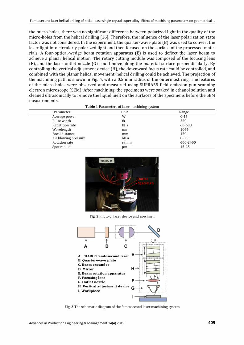
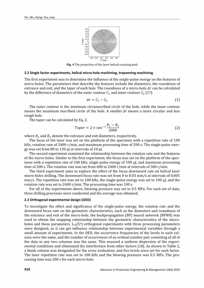
themicro‐holes,therewasnosignificantdifferencebetweenpolarizedlightinthequalityofthemicro‐holesfromthehelicaldrilling[16].Therefore,theinfluenceofthelaserpolarizationstatefactorwasnotconsidered.Intheexperiment,thequarter‐waveplate(B)wasusedtoconvertthelaserlightintocircularlypolarizedlightandthenfocusedonthesurfaceoftheprocessedmate‐rials. A four‐optical‐wedge beam rotation apparatus (E) is used to deflect the laser beam toachieveaplanarhelicalmotion.Therotarycuttingmodulewascomposedof the focusing lens(F), and the laseroutletnozzle (G)couldmovealong thematerial surfaceperpendicularly.Bycontrollingtheverticaladjustmentdevice(H),thedownwardfocusratecouldbecontrolled,andcombinedwiththeplanarhelicalmovement,helicaldrillingcouldbeachieved.TheprojectionofthemachiningpathisshowninFig.4,witha0.5mmradiusoftheoutermostring.Thefeaturesof themicro‐holeswere observed andmeasured using SUPRA55 field emission gun scanningelectronmicroscope(SEM).Aftermachining,thespecimensweresoakedinethanolsolutionandcleanedultrasonicallytoremovetheliquidmeltonthesurfacesofthespecimensbeforetheSEMmeasurements.
Table1ParametersoflasermachiningsystemParameter Unit RangeAveragepower W 0‐15Pulsewidth fs 250Repetitionrate kHz 60‐600Wavelength nm 1064Focaldistance mm 150Airblowingpressure MPa 0‐0.5Rotationrate r/min 600‐2400Spotradius μm 15‐25
Fig.2Photooflaserdeviceandspecimen
Fig.3Theschematicdiagramofthefemtosecondlasermachiningsystem
Yin, Wu, Dong, You, Liao
410 Advances in Production Engineering & Management 14(4) 2019
Fig.4Theprojectionofthelaserhelicalscanningpath
2.2 Single factor experiments, helical micro‐hole machining, trepanning machining
Thefirstexperimentwastodeterminetheinfluenceofthesingle‐pulseenergyonthefeaturesofmicro‐holes.Theparametersthatdescribethefeaturesincludethediameters,theroundnessofentranceandexit,andthetaperofeachhole.Theroundnessofamicro‐hole canbecalculatedbythedifferenceofdiametersoftheoutercontour andinnercontour [17].
(1)
Theoutercontouristheminimumcircumscribedcircleofthehole,whiletheinnercontourmeans themaximum inscribedcircleof thehole.A smaller meansamorecircularand lessroughhole.
ThetapercanbecalculatedbyEq.2.
22000
(2)
where and denotetheentranceandexitdiameters,respectively.Thefocusofthelaserwassetontheplatformofthespecimenwitharepetitionrateof100
kHz,rotationrateof2400r/min,andmaximumprocessingtimeof200s.Thesingle‐pulseener‐gywassetfrom80to130μJatintervalsof10μJ.
Thesecondexperimentexaminedtherelationshipbetweentherotationrateandthefeaturesofthemicro‐holes.Similartothefirstexperiment,thefocuswassetontheplatformofthespec‐imenwitharepetitionrateof100kHz,singlepulseenergyof100μJ,andmaximumprocessingtimeof200s.Therotationratewassetfrom600to2400r/minatintervalsof300r/min.
Thethirdexperimentaimstoexploretheeffectofthefocusdownwardrateonhelicallasermicro‐holesdrilling.Thedownwardfocusratewassetfrom0to0.03mm/satintervalsof0.005mm/s.Therepetitionratewassetto100kHz,thesingle‐pulseenergywassetto100μJ,andtherotationratewassetto2400r/min.Theprocessingtimewas100s.
Foralloftheexperimentsabove,blowingpressurewassetto0.5MPa.Foreachsetofdata,threedrillingprocesseswereconductedandtheaveragewasobtained.
2.3 Orthogonal experimental design (OED)
To investigate the effect and significance of the single‐pulse energy, the rotation rate and thedownwardfocusrateonthegeometriccharacteristics,suchasthediametersandroundnessoftheentranceandexitofthemicro‐hole,thebackpropagation(BP)neuralnetwork(BPNN)wasused to obtain themapping relationship between the geometric characteristics of themicro‐holesandtheseparameters.L25(54)orthogonalexperimentswiththreeprocessingparameterswere designed, as it can get influence relationship between experimental variables through asmallamountofexperiments. IntheOED,theoccurrencefrequenciesofthelevels ineachcol‐umnwerethesame,andthenumberofoccurrencesofanordinalnumberpairconsistingofallofthe data in any two columnswas the same. This ensured a uniformdispersion of the experi‐mentalconditionsandeliminatedtheinterferencefromotherfactors[18].AsshowninTable2,ablankcolumnwasdesignatedfortheerrorevaluation,andfivelevelsweresetforeachfactor.The laserrepetitionratewasset to100kHzand theblowingpressurewas0.5MPa.Thepro‐cessingtimewas200sforeachmicro‐hole.
Femtosecond laser helical drilling of nickel‐base single‐crystal super‐alloy: Effect of machining parameters on geometrical …
Advances in Production Engineering & Management 14(4) 2019 411
Table2 Factorsandlevelsoforthogonalexperiments Factor
Level
ASinglepulseenergy,
μJ
BRotationrate,(r·min‐1)
CFocusdownwardrate,
(mm·s‐1) Blank
1 60 1600 0.005 2 70 1800 0.013 80 2000 0.015 4 90 2200 0.025 100 2400 0.025
3. Results and discussion
3.1 Effect of single pulse energy
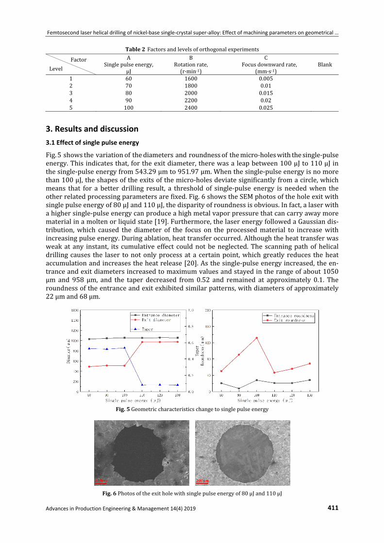
Fig.5showsthevariationofthediametersandroundnessofthemicro‐holeswiththesingle‐pulseenergy.Thisindicatesthat,fortheexitdiameter,therewasaleapbetween100μJto110μJinthesingle‐pulseenergyfrom543.29μmto951.97μm.Whenthesingle‐pulseenergyisnomorethan100μJ,theshapesoftheexitsofthemicro‐holesdeviatesignificantlyfromacircle,whichmeans that for a better drilling result, a threshold of single‐pulse energy is neededwhen theotherrelatedprocessingparametersarefixed.Fig.6showstheSEMphotosoftheholeexitwithsinglepulseenergyof80μJand110μJ,thedisparityofroundnessisobvious.Infact,alaserwithahighersingle‐pulseenergycanproduceahighmetalvaporpressurethatcancarryawaymorematerialinamoltenorliquidstate[19].Furthermore,thelaserenergyfollowedaGaussiandis‐tribution,which caused the diameter of the focus on the processedmaterial to increasewithincreasingpulseenergy.Duringablation,heattransferoccurred.Althoughtheheattransferwasweakat any instant, its cumulative effect couldnotbeneglected.The scanningpathofhelicaldrillingcauses the laser tonotonlyprocessat a certainpoint,whichgreatly reduces theheataccumulationandincreasestheheatrelease[20].Asthesingle‐pulseenergyincreased,theen‐tranceandexitdiametersincreasedtomaximumvaluesandstayedintherangeofabout1050μm and 958 μm, and the taper decreased from 0.52 and remained at approximately 0.1. Theroundnessoftheentranceandexitexhibitedsimilarpatterns,withdiametersofapproximately22μmand68μm.
Fig.5Geometriccharacteristicschangetosinglepulseenergy
Fig.6Photosoftheexitholewithsinglepulseenergyof80μJand110μJ
Yin, Wu, Dong, You, Liao
412 Advances in Production Engineering & Management 14(4) 2019
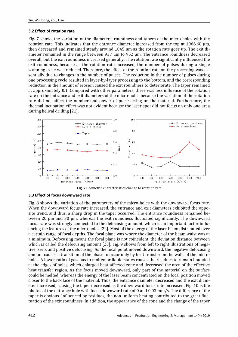
3.2 Effect of rotation rate
Fig.7 shows thevariationof thediameters, roundnessand tapersof themicro‐holeswith therotationrate.This indicatesthattheentrancediameter increasedfromthetopat1066.68μm,thendecreasedandremainedsteadyaround1045μmastherotationrategoesup.Theexitdi‐ameterremainedintherangebetween937μmto952μm.Theentranceroundnessdecreasedoverall,buttheexitroundnessincreasedgenerally.Therotationratesignificantlyinfluencedtheexit roundness, because as the rotation rate increased, the number of pulses during a singlescanningcyclewasreduced.Therefore,theeffectoftherotationrateontheprocessingwases‐sentiallyduetochangesinthenumberofpulses.Thereductioninthenumberofpulsesduringoneprocessingcycleresultedinlayer‐by‐layerprocessingtothebottom,andthecorrespondingreductionintheamountoferosioncausedtheexitroundnesstodeteriorate.Thetaperremainedatapproximately0.1.Comparedwithotherparameters,therewaslessinfluenceoftherotationrateontheentranceandexitdiametersofthemicro‐holesbecausethevariationoftherotationrate did not affect the number and power of pulse acting on the material. Furthermore, thethermalincubationeffectwasnotevidentbecausethelaserspotdidnotfocusononlyoneareaduringhelicaldrilling[21].
Fig.7Geometriccharacteristicschangetorotationrate
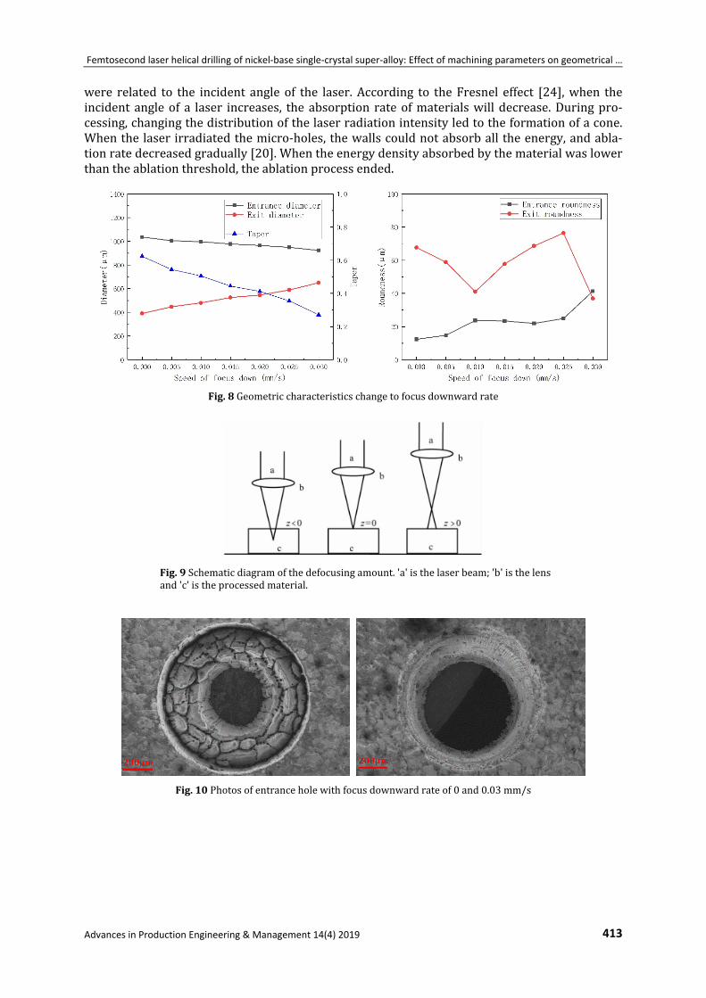
3.3 Effect of focus downward rate
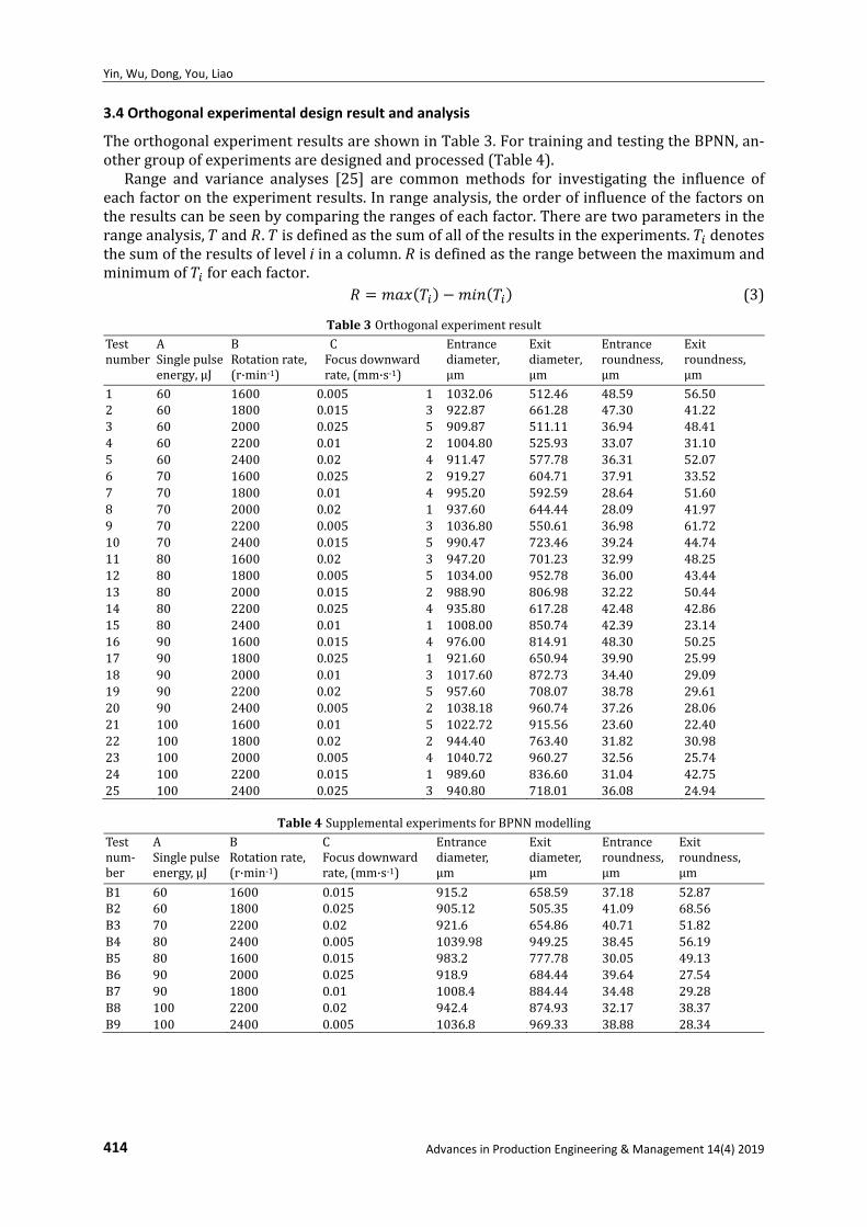
Fig.8showsthevariationoftheparametersofthemicro‐holeswiththedownwardfocusrate.Whenthedownwardfocusrateincreased,theentranceandexitdiametersexhibitedtheoppo‐sitetrend,andthus,asharpdropinthetaperoccurred.Theentranceroundnessremainedbe‐tween20μm and 30μm,whereas the exit roundness fluctuated significantly. The downwardfocusratewasstronglyconnectedtothedefocusingamount,whichisanimportantfactorinflu‐encingthefeaturesofthemicro‐holes[22].Mostoftheenergyofthelaserbeamdistributedoveracertainrangeoffocaldepths.Thefocalplanewaswherethediameterofthebeamwaistwasataminimum.Defocusingmeansthefocalplaneisnotcoincident,thedeviationdistancebetweenwhichiscalledthedefocusingamount[23].Fig.9showsfromlefttorightillustrationsofnega‐tive,zero,andpositivedefocusing.Asthefocalpointmoveddownward,thenegativedefocusingamountcausesatransitionofthephasetooccuronlybyheattransferonthewallsofthemicro‐holes.Alowerratioofgaseoustomoltenorliquidstatescausestheresiduestoremainboundedattheedgesofholes,whichenlargedheat‐affectedzoneanddecreasedtheareaoftheeffectiveheat transfer region. As the focusmoved downward, only part of thematerial on the surfacecouldbemelted,whereastheenergyofthelaserbeamconcentratedonthefocalpositionmovedclosertothebackfaceofthematerial.Thus,theentrancediameterdecreasedandtheexitdiam‐eterincreased,causingthetaperdecreasedasthedownwardfocusrateincreased.Fig.10isthephotosoftheentranceholewithfocusdownwardrateof0and0.03mm/s.Thedifferenceofthetaperisobvious.Influencedbyresidues,thenon‐uniformheatingcontributedtothegreatfluc‐tuationoftheexitroundness.Inaddition,theappearanceoftheconeandthechangeofthetaper
Femtosecond laser helical drilling of nickel‐base single‐crystal super‐alloy: Effect of machining parameters on geometrical …
Advances in Production Engineering & Management 14(4) 2019 413
were related to the incident angle of the laser.According to theFresnel effect [24],when theincident angleof a laser increases, theabsorption rateofmaterialswilldecrease.Duringpro‐cessing,changingthedistributionofthelaserradiationintensityledtotheformationofacone.Whenthelaserirradiatedthemicro‐holes,thewallscouldnotabsorball theenergy,andabla‐tionratedecreasedgradually[20].Whentheenergydensityabsorbedbythematerialwaslowerthantheablationthreshold,theablationprocessended.
Fig.8Geometriccharacteristicschangetofocusdownwardrate
Fig.9Schematicdiagramofthedefocusingamount.'a'isthelaserbeam;'b'isthelensand'c'istheprocessedmaterial.
Fig.10Photosofentranceholewithfocusdownwardrateof0and0.03mm/s
Yin, Wu, Dong, You, Liao
414 Advances in Production Engineering & Management 14(4) 2019
3.4 Orthogonal experimental design result and analysis
TheorthogonalexperimentresultsareshowninTable3.FortrainingandtestingtheBPNN,an‐othergroupofexperimentsaredesignedandprocessed(Table4).
Range and variance analyses [25] are commonmethods for investigating the influence ofeachfactorontheexperimentresults.Inrangeanalysis,theorderofinfluenceofthefactorsontheresultscanbeseenbycomparingtherangesofeachfactor.Therearetwoparametersintherangeanalysis, and . isdefinedasthesumofalloftheresultsintheexperiments. denotesthesumoftheresultsofleveliinacolumn. isdefinedastherangebetweenthemaximumandminimumof foreachfactor.
(3)
Table3OrthogonalexperimentresultTestnumber
ASinglepulseenergy,μJ
BRotationrate,(r·min‐1)
CFocusdownwardrate,(mm·s‐1)
Entrancediameter,μm
Exitdiameter,μm
Entranceroundness,μm
Exitroundness,μm
1 60 1600 0.005 1 1032.06 512.46 48.59 56.502 60 1800 0.015 3 922.87 661.28 47.30 41.223 60 2000 0.025 5 909.87 511.11 36.94 48.414 60 2200 0.01 2 1004.80 525.93 33.07 31.105 60 2400 0.02 4 911.47 577.78 36.31 52.076 70 1600 0.025 2 919.27 604.71 37.91 33.527 70 1800 0.01 4 995.20 592.59 28.64 51.608 70 2000 0.02 1 937.60 644.44 28.09 41.979 70 2200 0.005 3 1036.80 550.61 36.98 61.7210 70 2400 0.015 5 990.47 723.46 39.24 44.7411 80 1600 0.02 3 947.20 701.23 32.99 48.2512 80 1800 0.005 5 1034.00 952.78 36.00 43.4413 80 2000 0.015 2 988.90 806.98 32.22 50.4414 80 2200 0.025 4 935.80 617.28 42.48 42.8615 80 2400 0.01 1 1008.00 850.74 42.39 23.1416 90 1600 0.015 4 976.00 814.91 48.30 50.2517 90 1800 0.025 1 921.60 650.94 39.90 25.9918 90 2000 0.01 3 1017.60 872.73 34.40 29.0919 90 2200 0.02 5 957.60 708.07 38.78 29.6120 90 2400 0.005 2 1038.18 960.74 37.26 28.0621 100 1600 0.01 5 1022.72 915.56 23.60 22.4022 100 1800 0.02 2 944.40 763.40 31.82 30.9823 100 2000 0.005 4 1040.72 960.27 32.56 25.7424 100 2200 0.015 1 989.60 836.60 31.04 42.7525 100 2400 0.025 3 940.80 718.01 36.08 24.94
Table4SupplementalexperimentsforBPNNmodellingTestnum‐ber
ASinglepulseenergy,μJ
BRotationrate,(r·min‐1)
CFocusdownwardrate,(mm·s‐1)
Entrancediameter,μm
Exitdiameter,μm
Entranceroundness,μm
Exitroundness,μm
B1 60 1600 0.015 915.2 658.59 37.18 52.87B2 60 1800 0.025 905.12 505.35 41.09 68.56B3 70 2200 0.02 921.6 654.86 40.71 51.82B4 80 2400 0.005 1039.98 949.25 38.45 56.19B5 80 1600 0.015 983.2 777.78 30.05 49.13B6 90 2000 0.025 918.9 684.44 39.64 27.54B7 90 1800 0.01 1008.4 884.44 34.48 29.28B8 100 2200 0.02 942.4 874.93 32.17 38.37B9 100 2400 0.005 1036.8 969.33 38.88 28.34
Femtosecond laser helical drilling of nickel‐base single‐crystal super‐alloy: Effect of machining parameters on geometrical …
Advances in Production Engineering & Management 14(4) 2019 415
ThegreaterthevalueofRofthefactoris,thegreatertheinfluenceofthefactorisontheresult.Therangeanalysiscanbeusedtodeterminetheimpactorderofthe factors intuitively,but
the experimental error cannot be estimated. Moreover, the impactmagnitudes of the factorscannotbeindicated,especiallyfortheOEDwithmorethanthreelevels.Consideringthelimita‐tionofrangeanalysis,varianceanalysisisnecessarytodeterminetheimpactdegreesormagni‐tudesofthefactorsontheresults.Themostimportantparametersinthevarianceanalysisarethesumofsquareddeviationsforthetotal,foreachcolumn,anderror.
Thetotalsumofsquareddeviation( )andthetotalfreedom( )aredefinedasfollows:
(4)
1 (5)Thesumofsquareddeviationsforeachfactor( )andthefreedomforeach( )aredefined
asfollows:1
(6)
1 1,2, … , 1 (7)
Thesumofsquareddeviationsfortheexperimentalerror(SSE)anditsfreedom( )arede‐finedasfollows:
SSE SST (8)
(9)
Thevariancesofeachfactor( )andtheoneofexperimentalerror( )canbecalculatedbyasfollows:
(10)
(11)
wheretheFvalueisusedtoillustratethemagnitudesoftheeffectsonthefactors.Thisreflectstheratioofthesumofsquareddeviationsofeachfactortothatoftheexperimentalerror.Thus,theFvalueofeachfactorisasfollows:
(12)
InEqs.4to12, 25, 5, 4,and / 5forL25(54)OED.In theF‐distribution table, comparing with thevalueof ( , ) candeterminewhether
thefactoreffectontheresultsisprominentornot,whichiscalledtheF‐test.If islargerthan,thefactoreffectontheresultsisprominentandviceversa.Usually,α=0.05isthedemarca‐
tionofprominence,andα=0.01isthedemarcationofhighprominence[26].Inaddition,ifthevarianceofafactorislessthandoublethevarianceoftheexperimentalerror( <2 ),thisfactorcanbeseenasanerroranditssquareddeviationandfreedomwillbeaddedtothoseoftheerror.Intheresulttables,thefactorsmeetingthiscriterionaremarkedwithanasterisk'*'.
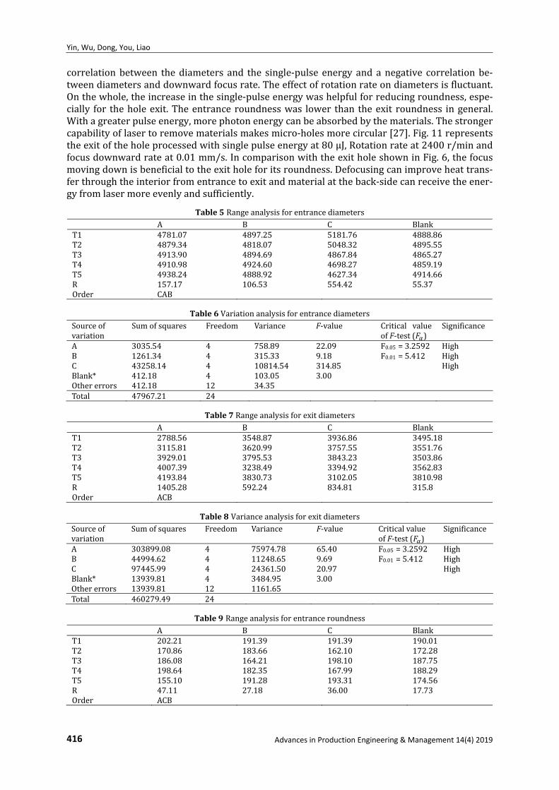
TheresultsoftherangeandvarianceanalysisareshowninTable5‐12.Allofthethreefactorshavesignificantinfluencesontheholediameters,whilethedownwardfocusrateandthesingle‐pulse energy are themost important factors affecting the entrance and exit diameter results,respectively.For theroundness, therotationratewastheweakest factor,andthesingle‐pulseenergywasthemaininfluencingfactor.Intherangeofexperimentaldata,therewasapositive
Yin, Wu, Dong, You, Liao
416 Advances in Production Engineering & Management 14(4) 2019
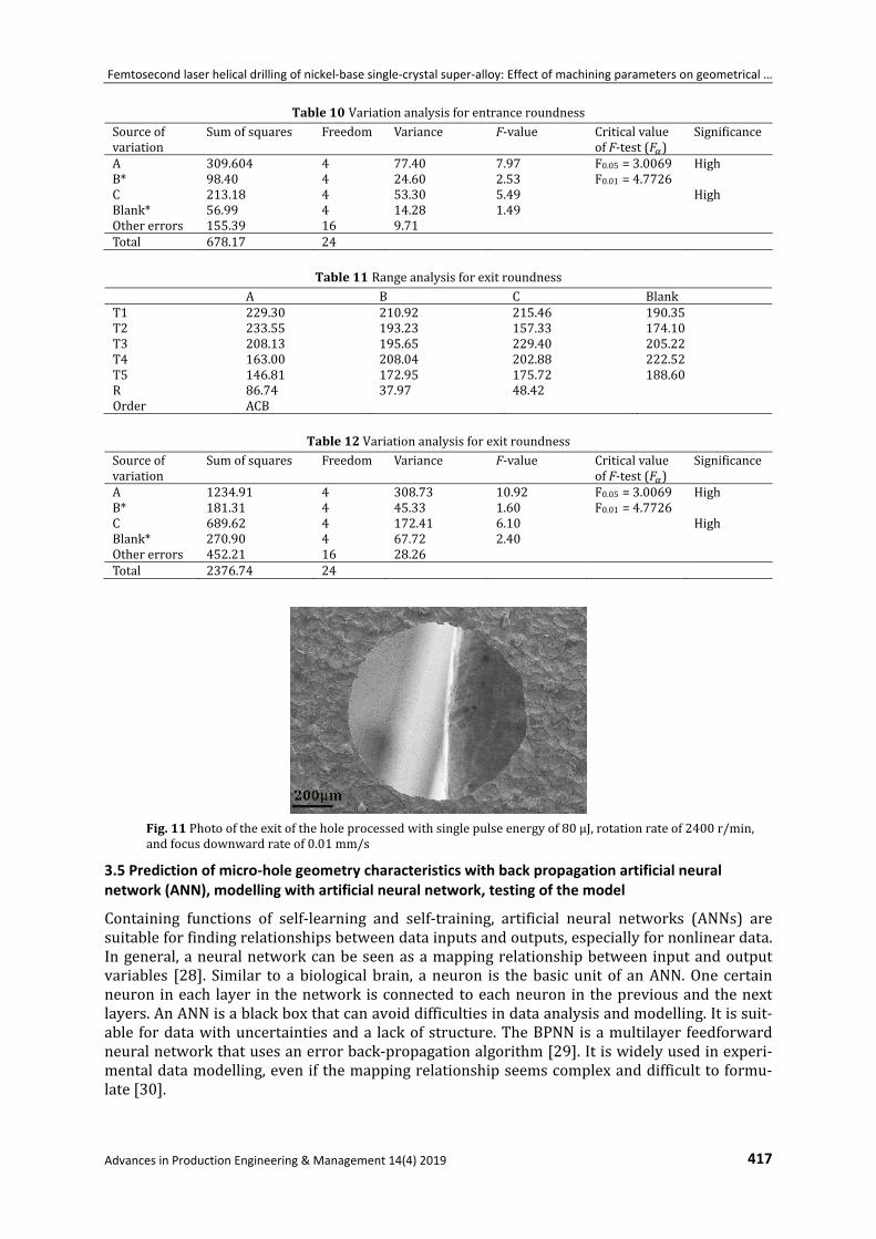
correlationbetween thediameters and the single‐pulse energy and anegative correlationbe‐tweendiametersanddownwardfocusrate.Theeffectofrotationrateondiametersisfluctuant.Onthewhole,theincreaseinthesingle‐pulseenergywashelpfulforreducingroundness,espe‐cially for theholeexit.Theentranceroundnesswas lower than theexit roundness ingeneral.Withagreaterpulseenergy,morephotonenergycanbeabsorbedbythematerials.Thestrongercapabilityoflasertoremovematerialsmakesmicro‐holesmorecircular[27].Fig.11representstheexitoftheholeprocessedwithsinglepulseenergyat80μJ,Rotationrateat2400r/minandfocusdownwardrateat0.01mm/s.IncomparisonwiththeexitholeshowninFig.6,thefocusmovingdownisbeneficialtotheexitholeforitsroundness.Defocusingcanimproveheattrans‐ferthroughtheinteriorfromentrancetoexitandmaterialattheback‐sidecanreceivetheener‐gyfromlasermoreevenlyandsufficiently.
Table5Rangeanalysisforentrancediameters A B C BlankT1 4781.07 4897.25 5181.76 4888.86T2 4879.34 4818.07 5048.32 4895.55T3 4913.90 4894.69 4867.84 4865.27T4 4910.98 4924.60 4698.27 4859.19T5 4938.24 4888.92 4627.34 4914.66R 157.17 106.53 554.42 55.37Order CAB
Table6Variationanalysisforentrancediameters
Sourceofvariation
Sumofsquares Freedom Variance F‐value Critical valueofF‐test( )
Significance
A 3035.54 4 758.89 22.09 F0.05=3.2592 HighB 1261.34 4 315.33 9.18 F0.01=5.412 HighC 43258.14 4 10814.54 314.85 HighBlank* 412.18 4 103.05 3.00 Othererrors 412.18 12 34.35 Total 47967.21 24
Table7Rangeanalysisforexitdiameters
A B C BlankT1 2788.56 3548.87 3936.86 3495.18T2 3115.81 3620.99 3757.55 3551.76T3 3929.01 3795.53 3843.23 3503.86T4 4007.39 3238.49 3394.92 3562.83T5 4193.84 3830.73 3102.05 3810.98R 1405.28 592.24 834.81 315.8Order ACB
Table8Varianceanalysisforexitdiameters
Sourceofvariation
Sumofsquares Freedom Variance F‐value CriticalvalueofF‐test( )
Significance
A 303899.08 4 75974.78 65.40 F0.05=3.2592 HighB 44994.62 4 11248.65 9.69 F0.01=5.412 HighC 97445.99 4 24361.50 20.97 HighBlank* 13939.81 4 3484.95 3.00 Othererrors 13939.81 12 1161.65 Total 460279.49 24
Table9Rangeanalysisforentranceroundness
A B C BlankT1 202.21 191.39 191.39 190.01T2 170.86 183.66 162.10 172.28T3 186.08 164.21 198.10 187.75T4 198.64 182.35 167.99 188.29T5 155.10 191.28 193.31 174.56R 47.11 27.18 36.00 17.73Order ACB
Femtosecond laser helical drilling of nickel‐base single‐crystal super‐alloy: Effect of machining parameters on geometrical …
Advances in Production Engineering & Management 14(4) 2019 417
Table10Variationanalysisforentranceroundness Sourceofvariation
Sumofsquares Freedom Variance F‐value CriticalvalueofF‐test( )
Significance
A 309.604 4 77.40 7.97 F0.05=3.0069 HighB* 98.40 4 24.60 2.53 F0.01=4.7726 C 213.18 4 53.30 5.49 HighBlank* 56.99 4 14.28 1.49 Othererrors 155.39 16 9.71 Total 678.17 24
Table11Rangeanalysisforexitroundness A B C BlankT1 229.30 210.92 215.46 190.35T2 233.55 193.23 157.33 174.10T3 208.13 195.65 229.40 205.22T4 163.00 208.04 202.88 222.52T5 146.81 172.95 175.72 188.60R 86.74 37.97 48.42 Order ACB
Table12VariationanalysisforexitroundnessSourceofvariation
Sumofsquares Freedom Variance F‐value CriticalvalueofF‐test( )
Significance
A 1234.91 4 308.73 10.92 F0.05=3.0069 HighB* 181.31 4 45.33 1.60 F0.01=4.7726 C 689.62 4 172.41 6.10 HighBlank* 270.90 4 67.72 2.40 Othererrors 452.21 16 28.26 Total 2376.74 24
Fig.11Photooftheexitoftheholeprocessedwithsinglepulseenergyof80μJ,rotationrateof2400r/min,andfocusdownwardrateof0.01mm/s
3.5 Prediction of micro‐hole geometry characteristics with back propagation artificial neural network (ANN), modelling with artificial neural network, testing of the model
Containing functions of self‐learning and self‐training, artificial neural networks (ANNs) aresuitableforfindingrelationshipsbetweendatainputsandoutputs,especiallyfornonlineardata.Ingeneral,aneuralnetworkcanbeseenasamappingrelationshipbetweeninputandoutputvariables [28]. Similar to a biologicalbrain, aneuron is thebasicunit of anANN.One certainneuron ineach layer in thenetwork isconnectedtoeachneuron in thepreviousandthenextlayers.AnANNisablackboxthatcanavoiddifficultiesindataanalysisandmodelling.Itissuit‐able fordatawithuncertaintiesanda lackofstructure.TheBPNNisamultilayer feedforwardneuralnetworkthatusesanerrorback‐propagationalgorithm[29].Itiswidelyusedinexperi‐mentaldatamodelling,evenifthemappingrelationshipseemscomplexanddifficulttoformu‐late[30].
Yin, Wu, Dong, You, Liao
418 Advances in Production Engineering & Management 14(4) 2019
BeforeestablishingtheBPNNmodel,experimentaldatashouldbenormalizedtoimprovetheefficiency and sensitivity while training and to prevent overfitting. To ensure that the BPNNmodelhastheidealextrapolationcapability,normalizedpre‐treatmentvaluesshouldbeintherangeof0.2to0.8.
Thedatapre‐treatmentcanbycalculatedasfollows:
0.8 0.2 0.2 (13)
Thereversedatapre‐treatmentcanbycalculatedasfollows:
0.20.8 0.2
(14)
InEqs.13and14, representsacertainvalueintheoriginaldataofeachfactor,and isthecorrespondingvalueinthepre‐treatmentdataofeachfactor, and arethemaxi‐mumandminimumvaluesinoriginaldataofeachfactor,respectively.
Ofallof the trainingalgorithmsused inBPNN, theLevenberg‐Marquardtalgorithmwasanoptionalone,asitcanadjustthenetworktrainingparametersautomaticallytoensurethenet‐workhasreal‐timeupdatingforitsapplicabletrainingmethods[31].Thecommontransferfunc‐tionsused inBPNNs include thehyperbolic tangentsigmoid function(tansig), logarithmicsig‐moidfunction(logsig),and linear function( ).Basedonpreviousresearch[32],usingthetansigfunctionasthetransferfunctionintheinput‐hiddenlayerandthelinearfunctioninhid‐den‐output layer can obtain thebest optimization inmostBPNNmodelling. For aBPNNwiththereormorelayers,thenetworkmodelcanapproximateanonlinearfunctioninfinitelyaslongastherearesufficientneurons[33].Therefore,theBPNNconfigurationusedinthisstudycon‐tainedone input layer,onehidden layerandoneoutput layer.Theneuralnetwork toolbox inMATLABwasusedtoestablishtheBPNNmodel.
Itisimportanttodeterminethepropernumberofneuronsinthehiddenlayers.Includingtoomanyneuronsmayleadtotheproblemslikeover‐fittingand localminima.Toensurethenet‐workperformanceandgeneralizationabilityaresufficientlyhigh,thestructureofthenetworkshould be as compact as possible to achieve high precision.With the experimental formulas∑ (where isforthenumberofdatafortheinputlayer, isthenumberofneuronsinhiddenlayer,and isthenumberofneuronsintheinputlayer), √ (where isthenumberofneuronsintheoutputlayer, ∈ 1,10 )[34],and log [35],thenumberofneuronswasselectedas26.Asaresult,theBPNNwiththetopologicalstructureof3‐26‐4waschosen.Aftertrainingthemodel49times,thenetworkconverged.
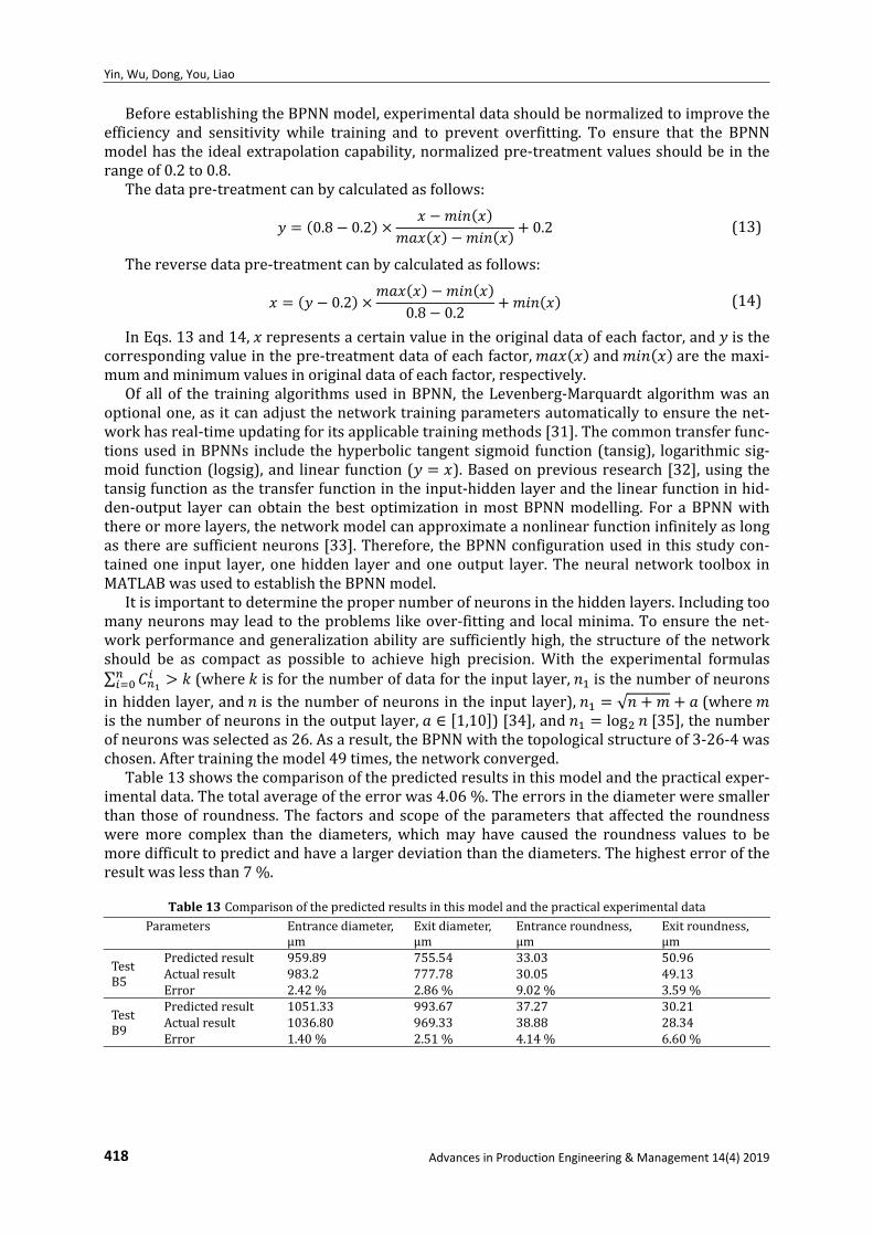
Table13showsthecomparisonofthepredictedresultsinthismodelandthepracticalexper‐imentaldata.Thetotalaverageoftheerrorwas4.06%.Theerrorsinthediameterweresmallerthan thoseof roundness.The factorsandscopeof theparameters thataffected theroundnessweremore complex than the diameters, whichmay have caused the roundness values to bemoredifficulttopredictandhavealargerdeviationthanthediameters.Thehighesterroroftheresultwaslessthan7%.
Table13ComparisonofthepredictedresultsinthismodelandthepracticalexperimentaldataParameters Entrancediameter,
μmExitdiameter,μm
Entranceroundness,μm
Exitroundness,μm
TestB5
Predictedresult 959.89 755.54 33.03 50.96Actualresult 983.2 777.78 30.05 49.13Error 2.42% 2.86 % 9.02 % 3.59%
TestB9
Predictedresult 1051.33 993.67 37.27 30.21Actualresult 1036.80 969.33 38.88 28.34Error 1.40% 2.51 % 4.14 % 6.60%
Femtosecond laser helical drilling of nickel-base single-crystal super-alloy: Effect of machining parameters on geometrical …
4. Conclusion By laser helical drilling experiments, rules for the machining parameters and geometric morpho-logical characteristics of micro-holes were determined in this study. In the range of 80 μJ to 130 μJ, with the single pulse energy increasing, the diameters increased. The Diameter and round-ness of the entrance and exit tended to be stable, while the taper exhibited a slight change. The increase in the rotation rate of the laser can lead to a fluctuation in a range in the values of diam-eters, but the taper remained almost invariant. The downward focus rate had a remarkable in-fluence on the characteristics of the micro-holes. With the defocusing rate increasing, the diame-ters changed greatly.
The OED shows that when the single-pulse energy was in the range of 60 μJ to 100 μJ, the fo-cus downward rate had the most significant effect on the entrance diameter. The single-pulse energy effect has the most significant effect on the exit diameter and the roundness.
In addition, a BP neural network was used to establish a mapping relationship based on the laser parameters and characteristics of micro-holes with an average error of less than 5 % and the maximum error of less than 7 %. Thus, the results of the laser drilling experiments were predictable, and this process was convenient for optimizing the process parameters, which could be applied to industrial practice.
Further research may concentrate on exploring the effect of other laser processing parame-ters, and different modelling methods for constructing the mapping relationship between the laser parameters and the geometrical morphologies of the micro-holes.
Acknowledgement The authors are grateful for the financial support provided by the National Natural Science Foundation of China (grant number 51705440), the Fundamental Research Funds for the Central Universities XMU (grant number 20720180072), the Aeronautical Science Foundation of China (grant number 20170368001), the Shenzhen Funda-mental Research Program (grant number JCYJ20170818141303656), and the Natural Science Foundation of Fujian Province, China (grant number 2019J01044).
References [1] Huang, H., Yang, L.-M., Liu, J. (2014). Micro-hole drilling and cutting using femtosecond fiber laser, Optical Engi-
neering, Vol. 53, No. 5, Article No. 051513, doi: 10.1117/1.OE.53.5.051513. [2] Rihakova, L., Chmelickova, H. (2017). Laser drilling of alumina ceramics using solid state Nd: YAG laser and QCW
fiber laser: Effect of process parameters on the hole geometry, Advances in Production Engineering & Manage-ment, Vol. 12, No. 4, 412-420, doi: 10.14743/apem2017.4.268.
[3] Shaegh, S.A.M., Pourmand, A., Nabavinia, M., Avci, H., Tamayol, A., Mostafalu, P., Ghavifekr, H.B., Aghdam, E.N., Dokmeci, M.R., Khademhosseini, A., Zhang, Y.S. (2018). Rapid prototyping of whole-thermoplastic microfluidics with built-in microvalves using laser ablation and thermal fusion bonding, Sensors and Actuators B: Chemical, Vol. 255, Part 1, 100-109, doi: 10.1016/j.snb.2017.07.138.
[4] Padmanabham, G., Bathe, R. (2018). Laser materials processing for industrial applications, Proceedings of the National Academy of Sciences, India Section A: Physical Sciences, Vol. 88, No. 3, 359-374, doi: 10.1007/s40010-018-0523-5.
[5] Ciurana, J., Arias, G., Ozel, T. (2009). Neural network modeling and particle swarm optimization (PSO) of process parameters in pulsed laser micromachining of hardened AISI H13 steel, Materials and Manufacturing Processes, Vol. 24, No. 3, 358-368, doi: 10.1080/10426910802679568.
[6] Dubey, A.K., Yadava, V. (2008). Laser beam machining – A review, International Journal of Machine Tools and Manufacture, Vol. 48, No. 6, 609-628, doi: 10.1016/j.ijmachtools.2007.10.017.
[7] Kamlage, G., Bauer, T., Ostendorf, A., Chichkov, B.N. (2003). Deep drilling of metals by femtosecond laser pulses, Applied Physics A, Vol. 77, No. 2, 307-310, doi: 10.1007/s00339-003-2120-x.
[8] Zoubir, A., Shah, L., Richardson, K., Richardson, M. (2003). Practical uses of femtosecond laser micro-materials processing, Applied Physics A, Vol. 77, No. 2, 311-315, doi: 10.1007/s00339-003-2121-9.
[9] Gruner, A., Schille, J., Loeschner, U. (2016). Experimental study on micro hole drilling using ultrashort pulse laser radiation, Physics Procedia, Vol. 83, 157-166, doi: 10.1016/j.phpro.2016.08.030.
[10] Wang, X.C., Zheng, H.Y., Chu, P.L., Tan, J.L., Teh, K.M., Liu, T., Ang, B.C.Y., Tay, G.H. (2010). Femtosecond laser drill-ing of alumina ceramic substrates, Applied Physics A, Vol. 101, No. 2, 271-278, doi: 10.1007/s00339-010-5816-8.
[11] Yang, L., Kong, X., Wang, Y., Ding, Y., Zhang, H., Chi, G. (2016). Laser micro-holes machining technology and its application, Aeronautical Manufacturing Technology, No. 19, 271-278, doi: 10.16080/j.issn1671-833x.2016.19. 032.
Advances in Production Engineering & Management 14(4) 2019 419
Yin, Wu, Dong, You, Liao
[12] Liu, Y., Zhang, R., Li, W., Wang, J., Yang, X., Cheng, L., Zhang, L. (2018). Effect of machining parameter on femto-second laser drilling processing on SiC/SiC composites, The International Journal of Advanced Manufacturing Technology, Vol. 96, No. 5-8, 1795-1811, doi: 10.1007/s00170-017-1163-7.
[13] Dausinger, F. (2002). Femtosecond technology for precision manufacturing: Fundamental and technical aspects, In: Proceedings of Third International Symposium on Laser Precision Microfabrication, Osaka, Japan, doi: 10.1117/ 12.486506.
[14] Abeln, T., Radtke, J., Dausinger, F. (1999). High precision drilling with short-pulsed solid-state lasers, In: Laser Institute of America – Proceedings – LIA, Vol. 88, 195-203, doi: 10.2351/1.5059302.
[15] Liao, C., Anderson, W., Antaw, F., Trau, M. (2018). Maskless 3D ablation of precise microhole structures in plas-tics using femtosecond laser pulses, ACS Applied Materials & Interfaces, Vol. 10, No. 4, 4315-4323, doi: 10.1021/ acsami.7b18029.
[16] Kraus, M., Ahmed, M.A., Michalowski, A., Voss, A., Weber, R., Graf, T. (2010). Microdrilling in steel using ultra-short pulsed laser beams with radial and azimuthal polarization, Optics Express, Vol. 18, No. 21, 22305-22313, doi: 10.1364/OE.18.022305.
[17] ISO 1101:2017 Geometrical product specifications (GPS) — Geometrical tolerancing — Tolerances of form, orientation, location and run-out, from https://www.iso.org/standard/66777.html, accessed October 27, 2019.
[18] Zhu, J., Chew, D.A.S., Lv, S., Wu, W. (2013). Optimization method for building envelope design to minimize carbon emissions of building operational energy consumption using orthogonal experimental design (OED), Habitat In-ternational, Vol. 37, 148-154, doi: 10.1016/j.habitatint.2011.12.006.
[19] Wang, C., Xue, S., Chen, G., Luan, D., Wang, S., Wang, Y., Wang, S., Liu, J., Wang, Z., Zhang, P. (2018). Influence of laser parameters on micro-hole drilling of Cu50Zr50 amorphous alloys foil, Ferroelectrics, Vol. 523, No. 1, 61-66, doi: 10.1080/00150193.2018.1391557.
[20] Fan, N.-N., Xia, Z.-D., Sun, X.-Y., Hu, Y.-W. (2016). Experimental study on stainless steel micro-hole trepanned by femtosecond laser, Laser & Infrared, Vol. 46, No. 10, 1200-1205, doi: 10.3969/j.issn.1001-5078.2016.10.006.
[21] Fornaroli, C., Holtkamp, J., Gillner, A. (2013). Laser-beam helical drilling of high quality micro holes, Physics Procedia, Vol. 41, 661-669, doi: 10.1016/j.phpro.2013.03.130.
[22] Wang, G.-A., Zhang, Y.-Z., Ni, X.-W., Lu, J. (2007). Effect of deviation distance to focal spot on nanosecond-pulsed-laser drilling rates in air, Chinese Journal of Lasers, Vol. 34, No. 12, 1621-1624.
[23] Zou, Z.-Q., Li, J., Hu, L.-Y. (2017). Diameter changing regularity with the laser parameters of nanosecond laser drilling, Optics & Optoelectronic Technology, Vol. 15, No. 5, 58-61.
[24] Verbeeck, J., Bertoni, G., Schattschneider, P. (2008). The Fresnel effect of a defocused biprism on the fringes in inelastic holography, Ultramicroscopy, Vol. 108, No. 3, 263-269, doi: 10.1016/j.ultramic.2007.06.007.
[25] Wu, X., Leung, D.Y.C. (2011). Optimization of biodiesel production from camelina oil using orthogonal experi-ment, Applied Energy, Vol. 88, No. 11, 3615-3624, doi: 10.1016/j.apenergy.2011.04.041.
[26] Li, X.J., Dong, Y.W., Yin, C.P., Zhao, Q., You, Y.C. (2018). Geometric parameters evolution experiment of hole during femtosecond laser helical drilling, Chinese Journal of Lasers, Vol. 45, No. 5, doi: 10.3788/CJL201845.0502008.
[27] Ren, N., Zhang, L., Wang, H., Xia, K., Shi, C. (2017). Orthogonal experiments and variance analysis in Nd:YAG pulsed laser trepanning drilling, Laser & Optoelectronics Progress, Vol. 54, No. 6, doi: 10.3788/LOP54.061408.
[28] Dhara, S.K., Kuar, A.S., Mitra, S. (2008). An artificial neural network approach on parametric optimization of laser micro-machining of die-steel, The International Journal of Advanced Manufacturing Technology, Vol. 39, No. 1-2, 39-46, doi: 10.1007/s00170-007-1199-1.
[29] Casalino, G. (2018). [INVITED] Computational intelligence for smart laser materials processing, Optics & Laser Technology, Vol. 100, 165-175, doi: 10.1016/j.optlastec.2017.10.011.
[30] Majumder, A. (2010). Comparison of ANN with RSM in predicting surface roughness with respect to process parameters in Nd:YAG laser drilling, International Journal of Engineering Science and Technology, Vol. 2, 5175-5186.
[31] Li, M., Wu, H., Wang, Y., Handroos, H., Carbone, G. (2017). Modified Levenberg–Marquardt algorithm for back-propagation neural network training in dynamic model identification of mechanical systems, Journal of Dynamic Systems, Measurement, and Control, Vol. 139, No. 3, Article No. 031012, doi: 10.1115/1.4035010.
[32] Guo, Q.-C., He, Z.-F. (2014). Economic forecasting model based on artificial neural network, Computing Technolo-gy and Automation, Vol. 33, No. 1, 132-136.
[33] Zhang, Y., Gao, X., Katayama, S. (2015). Weld appearance prediction with BP neural network improved by genetic algorithm during disk laser welding, Journal of Manufacturing Systems, Vol. 34, 53-59, doi: 10.1016/j.jmsy.2014. 10.005.
[34] Ding, S., Su, C., Yu, J. (2011). An optimizing BP neural network algorithm based on genetic algorithm, Artificial Intelligence Review, Vol. 36, No. 2, 153-162, doi: 10.1007/s10462-011-9208-z.
[35] Ai, J.L., Yang, X.Z. (2017). Fault diagnosis of aero-engine based on self-adaptive neural network, Scientia Sinica Technologica, Vol. 48, No. 3, 326-335, doi: 10.1360/N092017-00224.
420 Advances in Production Engineering & Management 14(4) 2019


![Advances in Production Engineering Management ISSN 1854 6250apem-journal.org/Archives/2017/APEM12-4_337-352.pdf · numbers [8] for each day in advance, and this is where artificial](https://img.pdfslide.us/doc/110x75/5f03db5d7e708231d40b1af8/advances-in-production-engineering-management-issn-1854-6250apem-numbers-8-for.jpg)