Embed Size (px)
Citation preview
Advances in generation of high-repetition-rateburst mode laser output
Naibo Jiang, Matthew C. Webster, and Walter R. Lempert*Departments of Mechanical Engineering and Chemistry, The Ohio State University,
201 West 19th Avenue, Columbus, Ohio 43210, USA
*Corresponding author: [email protected]
Received 10 July 2008; accepted 2 September 2008;posted 22 September 2008 (Doc. ID 98568); published 20 October 2008
It is demonstrated that the incorporation of variable pulse duration flashlamp power supplies into an Nd:YAG burst mode laser system results in very substantial increases in the realizable energy per pulse, thetotal pulse train length, and uniformity of the intensity envelope. As an example, trains of 20 pulses atburst frequencies of 50 and 20kHz are demonstrated with individual pulse energy at 1064nm of 220 and400mJ, respectively. Conversion efficiency to the second- (532nm) and third- (355nm) harmonic wave-lengths of∼50% and 35–40%, respectively, is also achieved. Use of the third-harmonic output of the burstmode laser as a pump source for a simple, home built optical parametric oscillator (OPO) produces pulsetrains of broadly wavelength tunable output. Sum-frequency mixing of OPO signal output at 622nmwithresidual output from the 355nm pump beam is shown to produce uniform bursts of tunable output at∼226nm, with individual pulse energy of∼0:5mJ. Time-correlated NO planar laser induced fluorescence(PLIF) image sequences are obtained in a Mach 3 wind tunnel at 500kHz, representing, to our knowl-edge, the first demonstration of NO PLIF imaging at repetition rates exceeding tens of hertz. © 2009Optical Society of America
OCIS codes: 190.4970, 190.7110, 280.2490, 120.1740.
1. Introduction
While there has been enormous progress in recentyears in the development and application of a varietyof optical diagnostic imaging techniques, the abilityto capture time-resolved or volumetric information isseverely constrained by limitations of available lasertechnology. Over the past several years, there hasbeen considerable effort expended to develop the cap-ability of generating “trains” of ∼20–30, or more,high-energy—high-repetition-rate Nd:YAG pulses,using the “pulse burst” approach [1–6]. While re-ported burst mode Nd:YAG systems differ in the de-tails of their design, they all share certain basiccharacteristics. Specifically, reported systems typi-cally utilize a low-power (of the order of 100mW, typ-ically) master oscillator (typically Nd:YAG) that is“sliced” into a burst train using either a pair of elec-
tro-optic Pockel cells [1–4] or an acousto-optic deflec-tor [5]. An exception is the system reported byDen Hartog et al. [6] in which a repetitively Q-switched diode-pumped Nd:YVO4 laser is used asthe master oscillator. The burst train is then ampli-fied in a series of flashlamp-pumped Nd:YAG or Nd:glass [6] amplifiers. Typical reported burst sequencesconsist of ∼8–40 pulses, with interpulse spacing aslow as 1 μs and individual pulse duration of between6 and 25ns. For all reported experimental resultsprevious to that which will be presented here, signif-icant energy pulses were demonstrated for burst se-quences no longer than ∼100−150 μs in duration,limited by the temporal gain profile resulting fromthe use of conventional fixed pulse duration flash-lamp power supplies, such as those which are usedfor ordinary Q-switched Nd:YAG laser systems. Thetotal energy per burst sequence was also limited tothe order of ∼1:5 J at 1064nm, divided approxi-mately equally but with not insignificant (typically�10–30% or more) modulation of the intensity
0003-6935/09/040B23-09$15.00/0© 2009 Optical Society of America
1 February 2009 / Vol. 48, No. 4 / APPLIED OPTICS B23
envelope. Burst trains typically have repetition ratesas high as 10Hz, although at high energy, operationat a few hertz (1–2) results in better beam quality.In this paper we report significant enhancement of
the achievable individual pulse energy, to as high as∼400mJ=pulse, the pulse train length, to∼1ms, anduniformity (�5%, or better) of the intensity enveloperesulting from incorporation of variable pulse dura-tion flashlamp power supplies. We also demonstrateplanar laser induced fluorescence (PLIF) imaging ofNO [7–9] at burst frequencies as high as 500kHzusing tunable ultraviolet burst mode output derivedfrom an optical parametric oscillator (OPO) [10]pumped by the third-harmonic output of the burstmode Nd:YAG system. To our knowledge, this workrepresents the first demonstration of NO PLIF ima-ging at repetition rates exceeding tens of hertz. Theonly comparable capability, to our knowledge, is thatreported by Kaminski et al. [11] and Kittler andDreizler [12]. Kaminski et al. used four individualand independent double-pulsed Nd:YAG lasers topump a single commercial dye laser, which was usedfor OH PLIF imaging. Starting with 270mJ per in-dividual pulse at 532nm, Kaminski et al. were ableto generate eight pulses at 282nm, with an averageenergy of ∼1mJ=pulse and a repetition rate of∼8kHz, constrained by the high-intensity pumpingrequirement of the dye laser. Kittler and Dreizlerused a frequency-doubled dye laser pumped by a5kHz Nd:YLF laser to obtain UV light at 283nmfor turbulent flame studies [12]. They obtained22 μJ=pulse at 283nm.
2. Experiments
A. Laser System
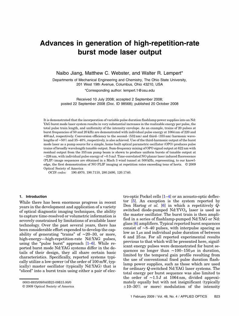
The burst mode Nd:YAG laser has been described indetail previously [1,2] and will therefore only be sum-marized here. As illustrated in Fig. 1, a continuouswave diode-pumped Nd:YAG ring laser serves asthe primary oscillator, the output of which is pream-plified in a double-pass flashlamp-pumped pulsedamplifier. The amplifier rod is 100mm in length by
6:3mm in diameter and is wedged at a few degreesto mitigate self-lasing. The resulting smooth pulse isformed into a “burst” train using a custom, dualPockel cell “slicer,” the output of which is furtheramplified in a series of four additional flashlamp-pumped amplifiers, with 6.3, 6.3, 9, and12:7mmdiameter × 100mmlength rods, respec-tively. While our previous work has utilized powersupplies with fixed pulse duration of∼300 μs (AnalogModules 8800 Series) to drive the amplifier flash-lamps, the measurements to be reported in this pa-per utilize new flashlamp supplies (Analog Modules8800V Series). These supplies have variable pulsewidth, between 0.3 and 2:0ms and maximum flash-lamp energy of 300, 400, and 600 J, respectively, forpumping the 6.3, 9, and 12:7mm rods. For typicallaser operation the lamp energy utilized scales ap-proximately linearly with burst duration. The funda-mental output at 1:06 μm is converted to either thesecond-harmonic wavelength (532nm), using a typeII KTP second-harmonic generation (SHG) crystal, orto the third-harmonic wavelength (355nm), using apair of noncritically phase matched type I LBO crys-tals, as described by Dergachev et al. [13]. As de-scribed in detail previously [2] a stimulated Brillouinscattering phase conjugate mirror (PCM), similar tothat which has been employed in pulsed dye lasers toremove amplified spontaneous emission [14], is in-serted between the third and the fourth amplifiers,the purpose of which is to eliminate a low intensitypedestal resulting from finite on/off contrast of thepulse slicer and to suppress amplified spontaneousemission growth in the forward direction. The finaloutput is a flexible “burst” of pulses, with interpulsespacing as short as 1 μs and individual pulse dura-tion as short as 4ns. The number and spacing ofthe pulses is quite flexible, limited by the 0:3–2:0msperiod for which the flashlamp-pumped amplifiershave significant gain. The spectral linewidth at532nm is ∼160MHz (FWHM) when measured usinga scanning Fabry–Perot etalon in front of the PCM,which is a factor of approximately 2 greater than theFourier transform limit of ∼55MHz for the 8:2ns(FWHM) duration of the individual pulses [15]. Itis additionally broadened to ∼320MHz by the PCMdue to the stimulated Brillouin scattering process[16,17]. The repetition rate of the burst sequenceis as high as 10Hz but is typically limited to1–4Hz when operating with burst envelopes exceed-ing ∼0:5ms due to thermal loading of the ampli-fier rods.
B. OPO System
NOPLIFmeasurements employ a simple, home built355nm pumped cavity that has been described in de-tail previously [10]. The “gain” medium consists of apair of 12mm long type I BBO crystals that are5mm × 7mm in cross section and arranged in a lin-ear cavity configuration. The crystals are oriented toprovide walk-off compensation between the pumpand the signal/idler beams, which provides higherFig. 1. Schematic diagram of the pulse burst laser system.
B24 APPLIED OPTICS / Vol. 48, No. 4 / 1 February 2009
effective gain for the relatively small cross-sectionalarea (∼3mm diameter) pump beam [18,19]. The cav-ity employs a broadband high reflector and outputcoupler coated for 20–30% reflectivity in the wave-length range of 600–850nm. This low-finesse cavityprovides feedback at both the signal and the idlerwavelengths, with measured round trip gain exceed-ing 104 at 18mJ of 355nm pump [10], greatly exceed-ing the cavity losses for both signal and idler waves.The 355nm pump beam is coupled into and out of thecavity using a pair of dichroic mirrors. In some casesthe pump beam is retroreflected, producing OPOgain for both directions of signal and idler propaga-tion, which otherwise, due to the phase matching re-quirement, occurs only in the propagation directionparallel to that of the pump. The total cavity lengthis ∼100mm, limited by the size of the current pump-mirror mounts. A single-frequency external-cavitydiode laser can be used to injection seed the cavity atthe idler [20,21] wavelength, which results in OPOoutput pulses with a time averaged linewidth of∼300MHz [16], as determined using a commercial(High Finesse SP7) Fizeau wavemeter system withresolution of ∼100MHz, according to manufacturer’sspecification. The seed radiation is injected throughthe output coupler using a Faraday-rotation opticalisolator in a manner similar to that employed pre-viously for injection seeding of a titanium:sapphirelaser [22]. The required 226nm radiation is producedby sum-frequency mixing of the signal output of theOPO, at 622nm, with residual from the 355nm pumpbeam.
C. Camera System
PLIF image sequences are captured using a Prince-ton Scientific Instruments PSI-IV framing ICCDcamera [23]. The basic PSI-IV image sensor consistsof an 80 × 160 array of 115 μm × 115 μm pixels, eachof which has its own integrated 28 element memorybuffer. Charge is shifted from the photo active area,which constitutes approximately 50% of the totalpixel area, to memory at a maximum frame rate of1MHz. After acquisition of the desired sequence,the image set is transferred to a PC. The PSI-IV isdesigned to enable up to four 80 × 160 image sensorsto be incorporated into a single camera, for a maxi-mum resolution of 160 × 320 pixels. The version usedfor this work consisted of a pair of sensors, with totalavailable resolution of 160 × 160 pixels. While not yetstudied in detail, the dynamic range of the PSI-IV,according to manufacturer’s specification, is ∼3000.A lens coupled UV sensitive microchannel plate in-tensifier with fast decaying phosphor (∼160ns ac-cording to manufacturer’s specification) providestime gating capability with minimum exposure timeof approximately 10ns. While also not yet studied indetail, it is noted that in the absence of well depthsaturation no spillover of intensity from one frameto the next has been observed.
3. Results and Discussion
A. Small Signal Gain and Sample Burst Trains
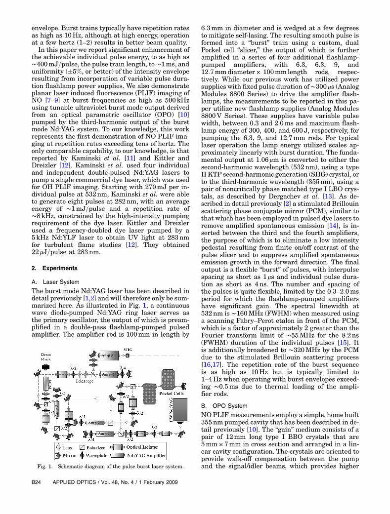
As a first step toward characterizing the perfor-mance of the new variable pulse width flashlamppower supplies Fig. 2 shows “small signal” gain ata variety of flashlamp driver pulse energies and timedurations. The data were obtained by substitution ofthe 8800V for the fixed pulse width power supplythat was previously used to pump the first amplifierin the chain, which is located between the master os-cillator and the pulse slicer. Note that the data shownin Fig. 2 were obtained for the same two-pass geome-try that is used in the actual laser system (quarter-wave plate, retroreflector, polarizer, and opticalisolator). The data given correspond to the net gain,including losses from the two-pass geometry optics.For comparison purposes, the time-dependent smallsignal gain is also given for the old, fixed pulse lengthpower supply, which has a nominal pulse duration of300 μs and energy input to the flashlamp of 40 J (thisamplifier has a single lamp). To improve the clarity ofthe display the time axis for this amplifier is shiftedby ∼100 μs. It can be seen that the original amplifierachieves a net two-pass gain of approximately 600,although the single pass gain, measured with no op-tical losses, is approximately 30–35. The new supply,operated with 300 μs pulse width and 40 J of energyinput to the lamp, has slightly higher net two-passpeak gain, approximately 700.
It can be seen in Fig. 2 that reasonably flat two-pass gain, exceeding ∼1000×, can be obtained forpulse durations as long as ∼1ms. Note that for theselong temporal envelopes the power supply is continu-ally recharging the Nd:YAG rods, which in somesense act as “optical capacitors,” storing photons fortime periods as long as ∼230 μs, the spontaneousradiative decay time of the 4F3=2 upper level of the1064nm lasing transition. For longer flashlampdurations the gain is continuously replenished asit is lost to stimulated and/or spontaneous emission.As will be shown below, for individual pulse spacingof the order of 20 μs or greater, there is very
Fig. 2. Two-pass small signal gain of analog modules model8800V variable pulse width power supply for a variety of lamp en-ergies and lamp charging pulse widths. The graph labeled “old”corresponds to fixed pulse width supply currently used for ampli-fier 1.
1 February 2009 / Vol. 48, No. 4 / APPLIED OPTICS B25
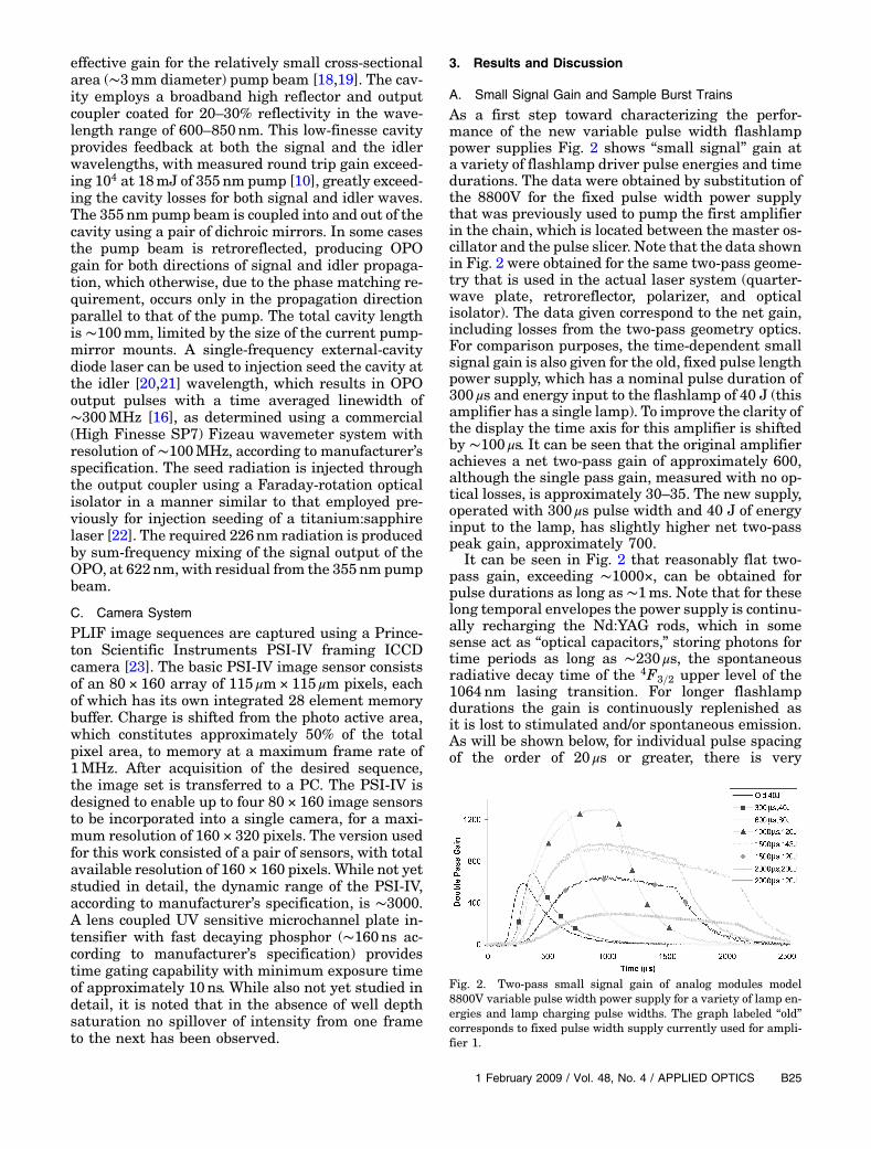
substantial refilling of the gain between pulses, lead-ing to higher individual pulse energies than those ty-pically achieved with the old fixed duration powersupplies.As an example, Fig. 3 shows four representative
burst sequences for the fundamental output at1064nm using the new power supplies. Note thatin all cases the uniformity of the envelope shownis representative of that obtained for any randomburst sequence. The upper left trace shows a tenpulse burst with 10 μs interpulse spacing (100kHzrepetition rate). The average energy per pulse is83mJ, but it is anticipated that this number canbe increased by a factor of approximately 2 by moreoptimal selection of flashlamp pulse durations foreach of the individual amplifiers and by optimizingthe relative delay between them.The upper right trace shows a burst of 20 pulses
with 20 μs spacing (50kHz). The average individualpulse energy for this case is 233mJ and, as can beseen, the uniformity of the individual pulses withinthe burst is quite good ð∼� 5%Þ. At this repetitionrate, similar to commercial “double pulse” Nd:YAGsystems, the time interval between the pulses is suf-ficient to allow partial refilling of the gain prior to thenext pulse, resulting in higher and more uniformpulse energy. In this regard we note that a customdesigned variable pulse width flashlamp supply willbe incorporated into a similar system currently un-der development as a source for high-repetition-rateThompson scattering [6]. By taking advantage ofgain refilling, and by adding high-energy Nd:glass fi-nal amplifier stages, individual pulse energies of
∼1–2 J, at 1064nm, are anticipated at burst frequen-cies of the order of 50kHz.
The lower left trace in Fig. 3 shows a sequence con-sisting of 20 pulses at 50 μs spacing (20kHz). Theaverage pulse energy is 400mJ=pulse, correspondingto a total extracted energy of 8 J. Such burst energiesare readily achievable due to increased gain refillingbetween the pulses. In this case, however, the unifor-mity of the intensity envelope, while still good, issomewhat degraded as the total burst duration(1ms) is now equal to the nominal duration of theflashlamp pulse, which for this case is 1ms. Finallythe bottom right trace shows a 99 pulse burst at 10 μsspacing, with an average individual pulse energy ofapproximately 27mJ. While this is somewhat low, itis more than enough for a variety of scattering baseddiagnostics. For example, we have recently employedthe planar Doppler velocimetry method to performquantitative velocity imaging at frame rates upto 250kHz using pulse bursts of ∼1–10mJ=individual pulse (at 532nm) [24]. Finally it is notedthat, due to limited sampling capability of our digital
Fig. 3. Representative burst sequences at 1064nm. The upper left is a 10 pulse sequence with 10 μs spacing and average individual pulseenergy of 83mJ. Upper right is a 20 pulse sequence with 20 μs spacing and 233mJ=pulse. The lower left is 20 pulses with 50 μs spacing. Theaverage individual pulse energy is 420mJ. The lower right is a 99 pulse sequence with 10 μs spacing, and the average individual pulseenergy is 27mJ.
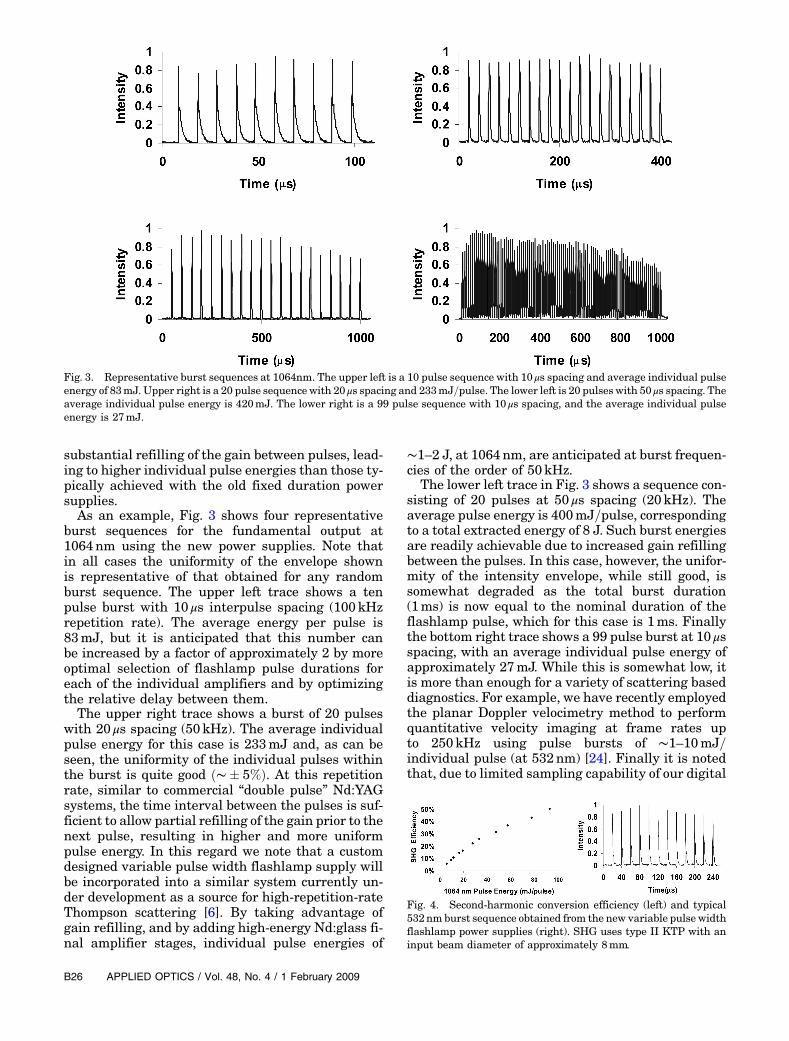
Fig. 4. Second-harmonic conversion efficiency (left) and typical532nm burst sequence obtained from the new variable pulse widthflashlamp power supplies (right). SHG uses type II KTP with aninput beam diameter of approximately 8mm.
B26 APPLIED OPTICS / Vol. 48, No. 4 / 1 February 2009
oscilloscope, a relatively high input impedance(∼10kΩ) was used to capture the burst sequencespresented in Fig. 3. The true individual pulse dura-tions are∼6, 4, and 4ns, for the 1064nm, OPO signal(see Fig. 5), and 226nm wavelengths (see Fig. 6), re-spectively.
B. Harmonic Conversion, OPO Output, and 226 nm Bursts
Figure 4 shows average second-harmonic conversionefficiency (left) and a typical 532nm burst (right) con-sisting of 12 pulses with 20 μs spacing and an approx-imate beam diameter of 8mm. For this case, SHGdata were obtained with a 10mm × 10mm × 10mmtype II KTP crystal at room temperature. It can beseen that the conversion efficiency reaches ∼50%for 1064 pulse energies of just under 100mJ, a resultwhich is similar to that previously reported usingtype I LBO [2]. It can also be seen that the second-harmonic pulse envelope is quite flat (�10%), verysimilar to that of the input 1064 pulse train. Longerpulse envelopes, while not shown, exhibit similar be-havior. It also appears that the conversion efficiencyis still increasing with increasing pulse energy,although due to concerns about potential damageto the KTP crystal the average single pulse energywas restricted to less than ∼100mJ.Figure 5 shows typical bursts for the Nd:YAG third
harmonic (left) and OPO signal (right). In this casethe signal burst is at 452nm, but other wavelengths,including the idler waves, are essentially identical.Similar to Fig. 4, the burst sequences in Fig. 5 consistof 12 pulses with 20 μs separation. For this case sec-ond- and third-harmonic wavelengths are generatedusing noncritically phase matched type I LBO, as
discussed above. Conversion efficiency, from funda-mental to third harmonic, is typically in the range35–40%, as per our previous work using type I LBO.Figure 6 shows a typical 20 pulse, 10 μs spacing burstsequence at 226nm, obtained from a 355nm OPO
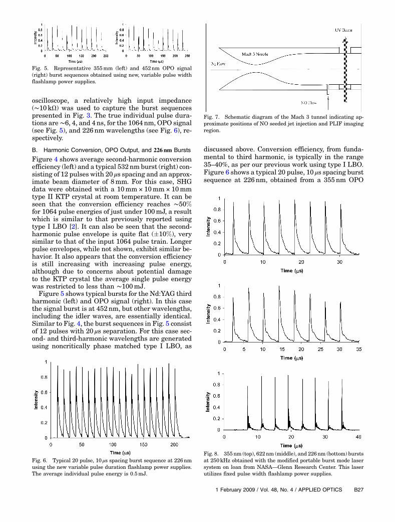
Fig. 5. Representative 355mm (left) and 452nm OPO signal(right) burst sequences obtained using new, variable pulse widthflashlamp power supplies.
Fig. 6. Typical 20 pulse, 10 μs spacing burst sequence at 226nmusing the new variable pulse duration flashlamp power supplies.The average individual pulse energy is 0:5mJ.
Fig. 7. Schematic diagram of the Mach 3 tunnel indicating ap-proximate positions of NO seeded jet injection and PLIF imagingregion.
Fig. 8. 355nm (top), 622nm (middle), and 226nm (bottom) burstsat 250kHz obtained with the modified portable burst mode lasersystem on loan from NASA—Glenn Research Center. This laserutilizes fixed pulse width flashlamp power supplies.
1 February 2009 / Vol. 48, No. 4 / APPLIED OPTICS B27
pump train with an average single pulse energy of34mJ. The corresponding individual pulse energyof the 622nm OPO signal is ∼4:8mJ, which whenmixed with the residual 355nm pump energy of∼11mJ results in an average single pulse energyof ∼0:5mJ at 226nm. As can be seen, the temporalenvelope of the 226nm burst is, again, uniform towithin approximately �10%. In this case the OPOwas operated without injection seeding, althoughseeded burst trains are essentially identical. Whilenot measured, the spectral linewidth at 226 whenthe OPO is operated broadband is estimated to be∼20 cm−1, limited by the acceptance bandwidth ofthe BBO sum-frequency generation step.
C. NO PLIF Demonstration
As a demonstration of the capabilities of the up-graded laser system, we have obtained some initialNO PLIF imaging sequences in the Mach 3 windtunnel shown in Fig. 7, which was used in previous
studies of supersonic magnetohydrodynamic flowcontrol [25]. As indicated in Fig. 7, the wind tunnelwas slightly modified by utilizing what was a pres-sure tap, located in the vicinity of the Mach 3 nozzleexit plane, as a small orifice with which a sonic jetorthogonal to the principal flow axis could be intro-duced. For the image sequences to be displayedbelow the primary stream stagnation pressure was350Torr of pure N2, corresponding to a static pres-sure of 10Torr at Mach 3. The NO seeded N2 jetwas operated with a back pressure of∼700Torr, withan NO seed fraction of 20%. This high seed fractionwas utilized for convenience, enabling an existingpremixed NO=N2 cylinder to be used. Note thatthe actual average seed fraction in the flow wasmuchsmaller (∼1%) due to the small jet orifice (1mm dia-meter) as compared to the ∼4:3mm ðheightÞ ×38mm ðspanÞ dimensions of the throat of the Mach3 nozzle.
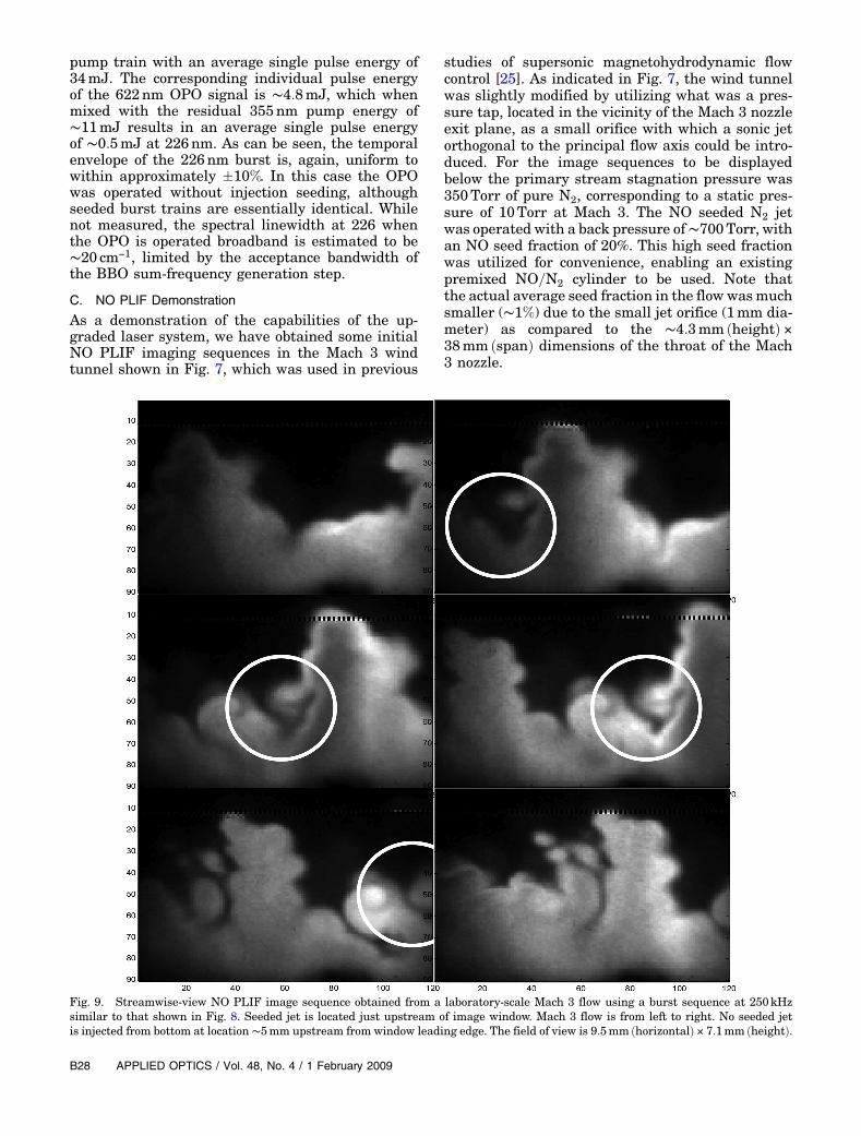
Fig. 9. Streamwise-view NO PLIF image sequence obtained from a laboratory-scale Mach 3 flow using a burst sequence at 250kHzsimilar to that shown in Fig. 8. Seeded jet is located just upstream of image window. Mach 3 flow is from left to right. No seeded jetis injected from bottom at location∼5mm upstream from window leading edge. The field of view is 9:5mm ðhorizontalÞ × 7:1mm ðheightÞ.
B28 APPLIED OPTICS / Vol. 48, No. 4 / 1 February 2009
Laser excitation employs the well-known A 2Σðv0 ¼0Þ←X 2
Q1=2ðv00 ¼ 0Þ transition in the vicinity of
226nm [7], which is generated by sum-frequencymixing of the OPO signal output at 622nm with re-sidual output from the 355nm OPO pump beam.Note that, as alluded to above, for the images tobe displayed below the OPO was operated with a sin-gle pass of the 355nm pump and without injectionseeding. In addition, for convenience, since the Mach3 flow facility was located in a different laboratorythan the burst mode laser, the NASA–Glenn Re-search Center portable burst mode system describedin [3], which has been loaned to our laboratory, wasutilized for the proof of concept measurements. In or-der to obtain sufficient individual pulse energy atburst frequencies exceeding 100kHz, the NASA–Glenn system was modified by the addition of a sec-ond 12:7mm YAG amplifier (for a total of seven).Figure 8 (top) shows a typical 355nm burst sequenceobtained from this system at 250kHz. The individual
pulse energy, similar to that of Fig. 6, is ∼35mJ. Themiddle and bottom traces show the OPO signal out-put at 622mm and final 226nm output (∼0:5mJ), re-spectively. Note that this laser system utilizes fixedpulse width flashlamp power supplies, with a pulseduration of ∼300 μs.
Figure 9 shows a typical sequence of NO PLIFimages obtained at a 250kHz burst frequency. Thefield of view is ∼9:5mm ðhorizontalÞ × 7:1mmðverticalÞ, centered 13mm downstream from the lo-cation of the 1mm diameter NO seeded sonic jet. TheMach 3 flow is from left to right, and the jet is in-jected from the bottom at a location approximately5mmupstream of the leading edge of the observationwindow. The sheet was formed with the combinationof a positive 20mm focal length cylindrical lens and apositive 150mm focal length spherical lens, produ-cing a sheet with thickness estimated to be∼50–100 μm. The PLIF signal was captured withan f =4:5–105mm focal length UV lens, with an
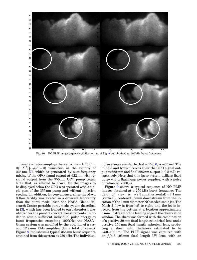
Fig. 10. NO PLIF image sequence similar to that of Fig. 9 but obtained at 500kHz burst frequency.
1 February 2009 / Vol. 48, No. 4 / APPLIED OPTICS B29
approximate 1∶1 imaging conjugate ratio and collec-tion f number equal to approximately 9. The inten-sifier was operated with gain equal to approximately85% of its maximum and gate duration of 100ns.While this facility was not designed as a “jet in crossflow,” the evolution and downstream progression oflarge scale structures formed by the interaction be-tween the jet and the main flow are clearly evident.Despite the relatively low single pulse laser energy,the NO containing portion of the images exhibits asignal intensity level of approximately 60–80% ofthe full quantum well, which for the PSI-IV camerais ∼30; 000 photoelectrons. (The read noise, accord-ing to manufacturer’s specification, is ∼5–10 photo-electrons.) Figure 10 shows an image sequenceobtained at 500kHz burst frequency. Despite thesomewhat limited spatial resolution of the framingCCD camera, the evolution and downstream propa-gation of large scale turbulent structures is veryclearly captured at this higher imaging frame rate.
4. Conclusions
Very significant enhancement of the achievable indi-vidual pulse energy of burst mode Nd:YAG laser sys-tems has been demonstrated by incorporation ofvariable pulse duration flashlamp power suppliesto as high as 230mJ=pulse for interpulse spacingof 20 μs and 400mJ=pulse for interpulse spacing of50 μs. An increase in the achievable pulse train dura-tion to ∼1ms and train uniformity to ∼� 5% or bet-ter have also been demonstrated. In combinationwith a simple home built optical parametric oscilla-tor system, planar laser induced fluorescence ima-ging of NO has been achieved in a Mach 3 windtunnel at burst frequencies as high as 500kHz. Toour knowledge, this work represents the first demon-stration of NO PLIF imaging at repetition rates ex-ceeding tens of hertz.
The authors acknowledge Mark Wernet for provid-ing the opportunity to utilize the NASA Glenn Re-search Center burst mode laser system for thiswork. The authors also acknowledge the support ofNASA Langley Research Center—Paul DanehyTechnical Monitor, the U.S. Air Force Research La-boratory—Propulsion Directorate, the Air Force Of-fice of Scientific Research—Program in UnsteadyAerodynamics and Hypersonics, and PrincetonScientific Instruments, Inc.
References1. P. Wu, W. R. Lempert, and R. B. Miles, “MHz pulse-burst laser
system and visualization of shock-wave boundary-layer inter-action in aMach 2.5 wind tunnel,”AIAA J. 38, 672–679 (2000).
2. B. Thurow, N. Jiang, M. Samimy, and W. Lempert, “Narrow-linewidth megahertz-rate pulse-burst laser for high-speedflow diagnostics,” Appl. Opt. 43, 5064–5073 (2004).
3. M. Wernet and A. B. Opalskii, “Development and applicationof a MHz frame rate digital Particle Image Velocimetry sys-tem,” in 24th Aerodynamic Measurement Technology &Ground Testing Conference Rep. AIAA-2004-2184 (AmericanInstitute of Aeronautics and Astronautics, 2004).
4. A. L. Kastengren, J. C. Dutton, and G. S. Elliott, “Large-scalestructure visualization and convection velocity in supersonicblunt-base cylinder wakes,” Phys. Fluids 19, 015103(2007).
5. B. Thurow and A. Satija, “A design of MHz repetitionrate pulse burst laser system at Auburn University,” in44th AIAA Aerospace Sciences Meeting, Rep. AIAA-2006-1384 (American Institute of Aeronautics and Astronau-tics, 2004).
6. D. J. Den Hartog, N. Jiang, and W. R. Lempert, “A pulseburst laser system for high repetition rate Thomsonscattering diagnostic,” accepted for publication in Rev. Sci.Instrum.
7. G. Kychakoff, K. Knapp, R. D. Howe, and R. K. Hanson, “Flowvisualization in combustion gases using nitric oxide fluores-cence,” AIAA J. 22, 153–154 (1984).
8. B. K. McMillan, J. L. Palmer, and R. K. Hanson, “Temporallyresolved, two-line fluorescence imaging of NO temperature ina transverse jet in a supersonic cross flow,” Appl. Opt. 32,7532–7545 (1993).
9. J. S. Fox, A. F. P. Houwing, P. M. Danehy, M. J. Gaston,N. R. Muidford, and S. L. Gai, “Mole-fraction-sensitive ima-ging of hypermixing shear layers,” J. Propul. Power 17,284–292 (2001).
10. N. Jiang, W. R. Lempert, G. L. Switzer, T. R. Meyer, andJ. R. Gord, “A narrow-linewidth MHz-repetition-rate opticalparametric oscillator for high-speed flow and combustion di-agnostics,” Appl. Opt. 47, 64–71 (2008).
11. C. F. Kaminski, J. Hult, and M. Alden, “High repetition rateplanar laser induced fluorescence of OH in a non-premixedflame,” Appl. Phys. B. 68, 757–760 (1999).
12. C. Kittler and A. Dreizler, “Cinematographic imaging of hy-droxyl radicals in turbulent flames by planar laser-inducedfluorescence up to 5kHz repetition rate,” Appl. Phys. B. 89,163–166 (2007).
13. A. Y. Dergachev, B. Pati, and P. F. Moulton, “Efficient third-harmonic generation with a Ti:sapphire laser,” in AdvancedSolid State Lasers, 1999 OSA Technical Digest Series (OpticalSociety of America, 1999), paper PD3.
14. C. K. Ni and A. H. Kung, “Effective suppression of amplifiedspontaneous emission by stimulated Brillouin scatteringphase conjugation,” Opt. Lett. 21, 1673–1675 (1996).
15. R. N. Bracewell, The Fourier Transform and Its Applications,2nd ed.(McGraw-Hill, 1986).
16. H. Yoshida, V. Kmetik, H. Fujita, M. Nakatsuka, T. Yamanaka,and K. Yoshida, “Heavy fluorocarbon liquids for a phase-conjugated stimulated Brillouin scattering mirror,” Appl.Opt. 36, 3739–3744 (1997).
17. A. L. Gaeta and R. W. Boyd, “Stochastic dynamics of stimu-lated Brillouin scattering in an optical fiber,” Phys. Rev A44, 3205–3209 (1991).
18. D. J. Armstrong, W. J. Alford, T. D. Raymond, A. V. Smith, andM. S. Bowers, “Parametric amplification and oscillation withwalkoff-compensating crystals,” J. Opt. Soc. Am. B 14, 460–474 (1997).
19. W. R. Bosenberg, W. S. Pelouch, and C. L. Tang, “High-efficiency and narrow-linewidth operation of a two-crystalβ-BaB2O4optical parametric oscillator,” Appl. Phys. Lett. 55,1952–1954 (1989).
20. W. D. Kulatilaka, T. N. Anderson, T. L. Bougher, andR. P. Lucht, “Development of injection-seeded, pulsedoptical parametric generator/oscillator systems for high-resolution spectroscopy,” Appl. Phys. B 80, 669–680(2005).
21. J. A. J. Fitzpatrick, O. V. Checkhlov, J. M. F. Elks, andC. M. Western, “An injection seeded narrow bandwidth pulsedoptical parametric oscillator and its application to the
B30 APPLIED OPTICS / Vol. 48, No. 4 / 1 February 2009

investigation of hyperfine structure in the PF radical,”J. Chem. Phys. 115, 6920–6930 (2001).
22. W. Lee and W. Lempert, “Enhancement of spectral purity ofinjection-seeded titanium:sapphire laser by cavity lockingand stimulated Brillouin scattering,” Appl. Opt. 42, 4320–4326 (2003).
23. W. R. Lempert, P. Wu, B. Zhang, R. B. Miles, J. L. Lowrance,V. Mastracola, and W. F. Kosonocky, “Pulse-burst lasersystem for high speed flow diagnostics,” in 34th AIAA
Aerospace Sciences Meeting, Rep. AIAA-1996-0500 (AmericanInstitute of Aeronautics and Astronautics, 1996).
24. B. Thurow, N. Jiang, W. Lempert, and M. Samimy, “Develop-ment of megahertz-rate planar Doppler velocimetry for highspeed flows,” AIAA J. 43, 500–511 (2005).
25. M. Nishihara, N. Jiang, J. W. Rich, W. R. Lempert,I. V. Adamovich, and S. Gogineni, “Low-temperature superso-nic boundary layer control using repetitively pulsed MHD for-cing,” Phys. Fluids 17, 106102 (2005).
1 February 2009 / Vol. 48, No. 4 / APPLIED OPTICS B31