Embed Size (px)
Citation preview
Advances in CMP Pad Conditioning A Scott Lawing, PhD Technology Director, Kinik North America/Europe Elbert Chou Managing Director, Kinik Company Asa Yamada Business Director, Kinik North America/Europe
Pyradia is registered trademark of the Kinik Company
NCCAVS CMPUG Symposium on CMP Technology and Market Trends July 16, 2015, Semicon West, SanFrancisco, CA
Outline
• Pad Conditioning Background
• The Importance of Conditioning
• Texture Generation
• Process Interactions
• The Evolution of Conditioning Technology
• The State of the Art and the Future of Conditioning
• Conclusions
CMP Pad Conditioning Fundamentals
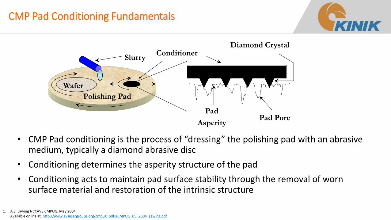
• CMP Pad conditioning is the process of “dressing” the polishing pad with an abrasive medium, typically a diamond abrasive disc
• Conditioning determines the asperity structure of the pad
• Conditioning acts to maintain pad surface stability through the removal of worn surface material and restoration of the intrinsic structure
Polishing Pad
Wafer
Conditioner Slurry
Pad
Asperity Pad Pore
Diamond Crystal
1. A.S. Lawing NCCAVS CMPUG, May 2004. Available online at: http://www.avsusergroups.org/cmpug_pdfs/CMPUG_05_2004_Lawing.pdf
Surface Height Probability Distributions
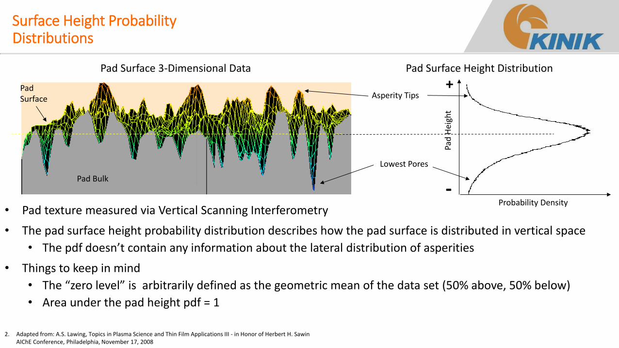
• Pad texture measured via Vertical Scanning Interferometry
• The pad surface height probability distribution describes how the pad surface is distributed in vertical space
• The pdf doesn’t contain any information about the lateral distribution of asperities
• Things to keep in mind
• The “zero level” is arbitrarily defined as the geometric mean of the data set (50% above, 50% below)
• Area under the pad height pdf = 1
Lowest Pores
Asperity Tips
Pad
Hei
ght
Probability Density
Pad Surface 3-Dimensional Data Pad Surface Height Distribution
Pad Bulk
Pad Surface
+
-
2. Adapted from: A.S. Lawing, Topics in Plasma Science and Thin Film Applications III - in Honor of Herbert H. Sawin AIChE Conference, Philadelphia, November 17, 2008
The Three Components of Pad Texture
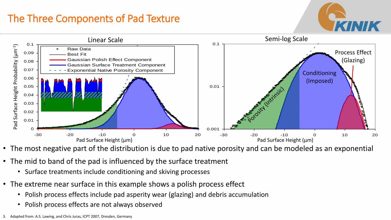
• The most negative part of the distribution is due to pad native porosity and can be modeled as an exponential
• The mid to band of the pad is influenced by the surface treatment • Surface treatments include conditioning and skiving processes
• The extreme near surface in this example shows a polish process effect • Polish process effects include pad asperity wear (glazing) and debris accumulation
• Polish process effects are not always observed
0.001
0.01
0.1
-30 -20 -10 0 10 20
0
0.01
0.02
0.03
0.04
0.05
0.06
0.07
0.08
0.09
0.1
-30 -20 -10 0 10 20
Raw Data
Best Fit
Gaussian Polish Effect Component
Gaussian Surface Treatment Component
Exponential Native Porosity Component
Pad
Su
rfac
e H
eigh
t P
rob
abili
ty (
µm
-1)
Pad Surface Height (µm) Pad Surface Height (µm)
Semi-log Scale Linear Scale
Conditioning (Imposed)
Process Effect (Glazing)
3. Adapted from: A.S. Lawing, and Chris Juras, ICPT 2007, Dresden, Germany
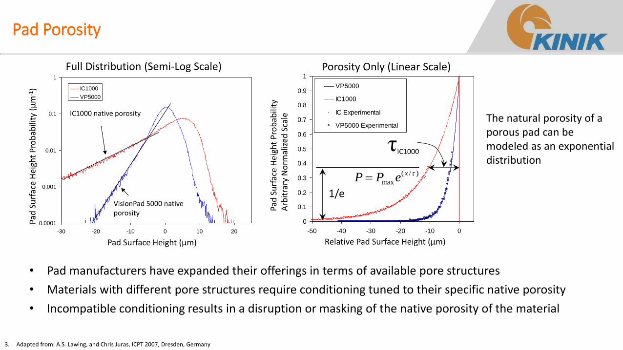
Pad Porosity
• Pad manufacturers have expanded their offerings in terms of available pore structures
• Materials with different pore structures require conditioning tuned to their specific native porosity
• Incompatible conditioning results in a disruption or masking of the native porosity of the material
0.0001
0.001
0.01
0.1
1
-30 -20 -10 0 10 20
IC1000
VP5000
Pad
Su
rfac
e H
eigh
t P
rob
abili
ty (
µm
-1)
Pad Surface Height (µm)
IC1000 native porosity
VisionPad 5000 native porosity
Full Distribution (Semi-Log Scale)
0
0.1
0.2
0.3
0.4
0.5
0.6
0.7
0.8
0.9
1
-50 -40 -30 -20 -10 0
VP5000
IC1000
IC Experimental
VP5000 Experimental
1/e
τIC1000
Relative Pad Surface Height (µm)
Pad
Su
rfac
e H
eigh
t P
rob
abili
ty
Arb
itra
ry N
orm
aliz
ed S
cale
)/(
max
xePP
Porosity Only (Linear Scale)
The natural porosity of a porous pad can be modeled as an exponential distribution
3. Adapted from: A.S. Lawing, and Chris Juras, ICPT 2007, Dresden, Germany
-50 -30 -10 10 30
Height (µm)
Fre
quen
cy (
arb.
uni
ts)
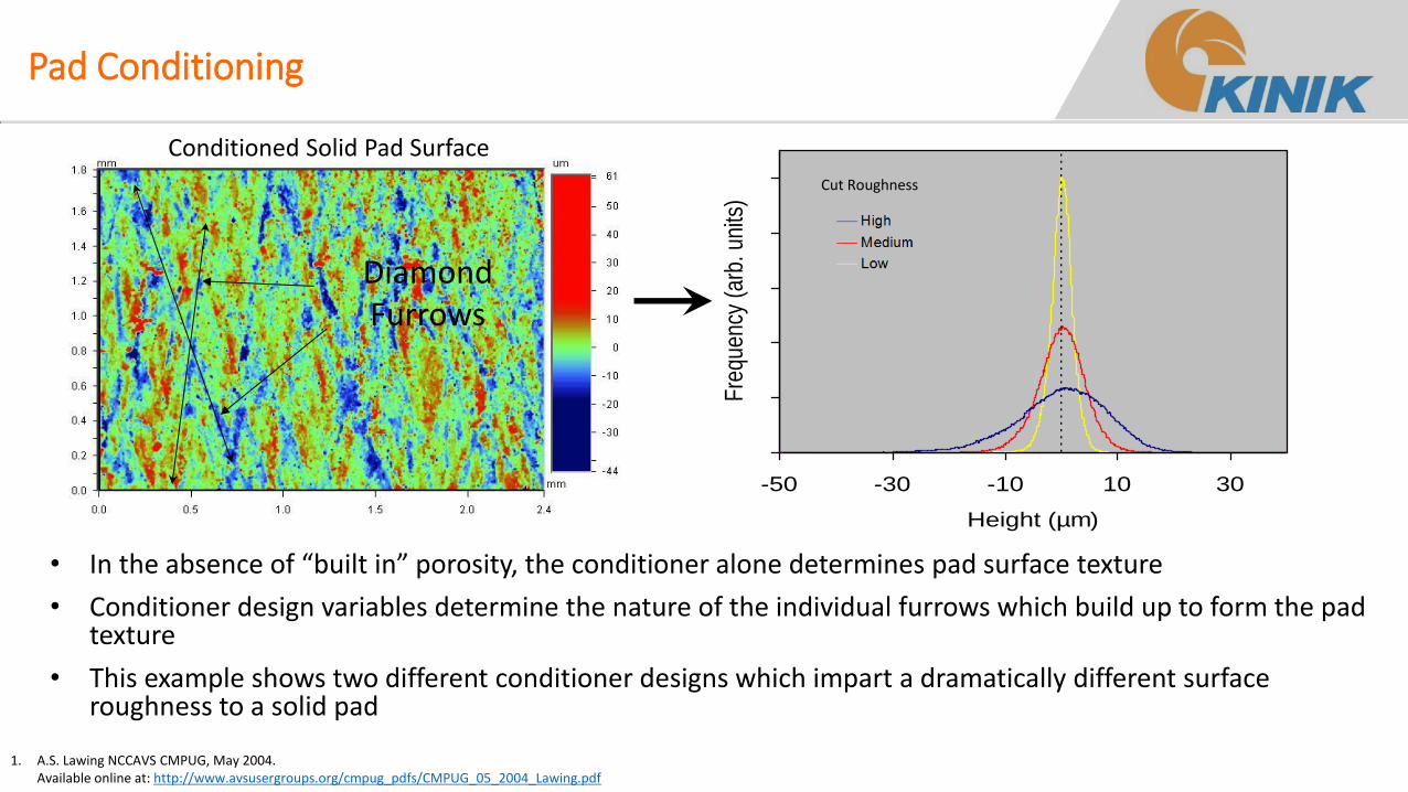
Pad Conditioning
• In the absence of “built in” porosity, the conditioner alone determines pad surface texture
• Conditioner design variables determine the nature of the individual furrows which build up to form the pad texture
• This example shows two different conditioner designs which impart a dramatically different surface roughness to a solid pad
Diamond Furrows
Conditioned Solid Pad Surface
Cut Roughness
1. A.S. Lawing NCCAVS CMPUG, May 2004. Available online at: http://www.avsusergroups.org/cmpug_pdfs/CMPUG_05_2004_Lawing.pdf
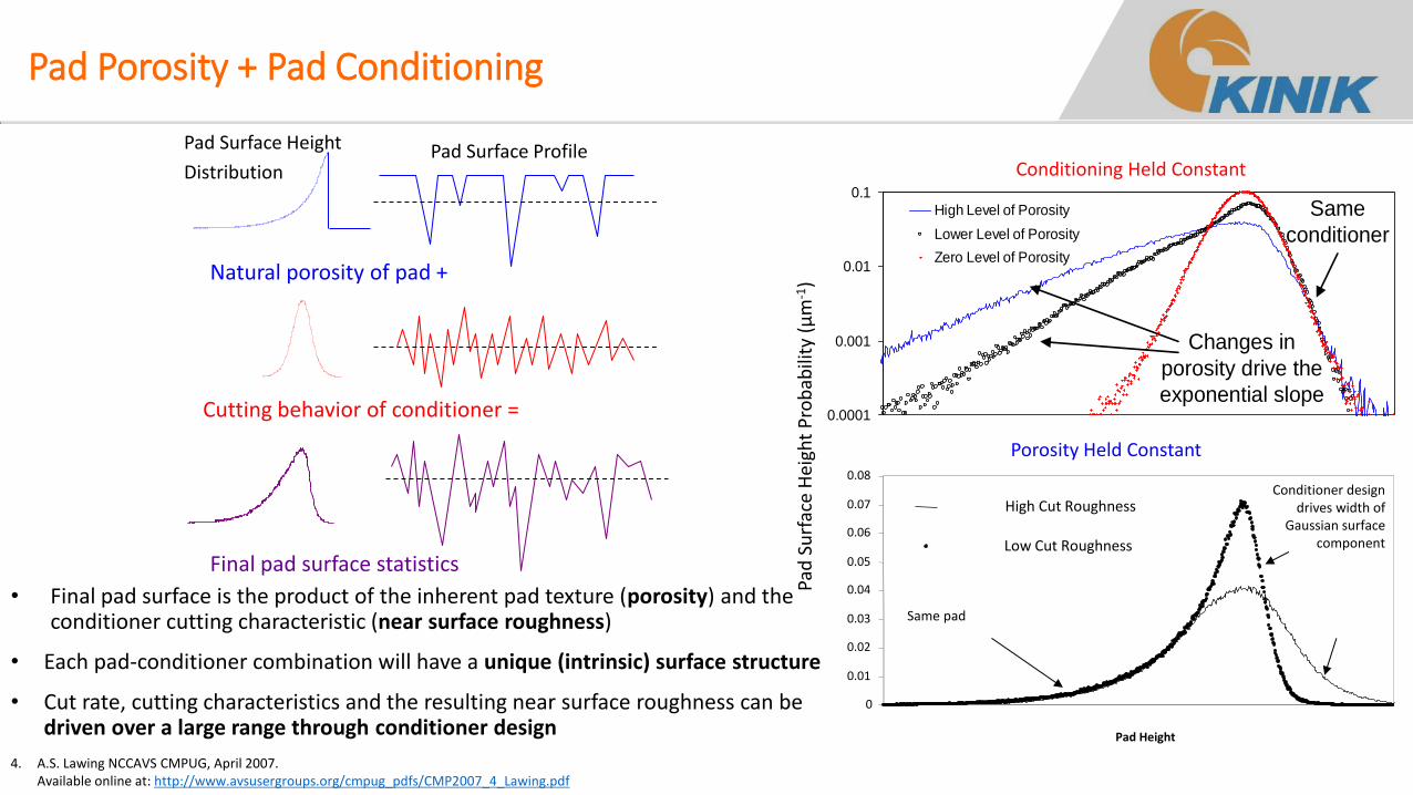
Pad Porosity + Pad Conditioning
Natural porosity of pad +
Cutting behavior of conditioner =
Final pad surface statistics
Pad Surface Profile Pad Surface Height
Distribution
• Final pad surface is the product of the inherent pad texture (porosity) and the conditioner cutting characteristic (near surface roughness)
• Each pad-conditioner combination will have a unique (intrinsic) surface structure
• Cut rate, cutting characteristics and the resulting near surface roughness can be driven over a large range through conditioner design
0.0001
0.001
0.01
0.1
High Level of Porosity
Lower Level of Porosity
Zero Level of Porosity
Changes in
porosity drive the
exponential slope
Same
conditioner
Conditioning Held Constant
Porosity Held Constant
0
0.01
0.02
0.03
0.04
0.05
0.06
0.07
0.08
Pad Height
High Cut Roughness
Low Cut Roughness
Conditioner design drives width of
Gaussian surface component
Same pad
Pad
Su
rfac
e H
eigh
t P
rob
abili
ty (
µm
-1)
4. A.S. Lawing NCCAVS CMPUG, April 2007. Available online at: http://www.avsusergroups.org/cmpug_pdfs/CMP2007_4_Lawing.pdf
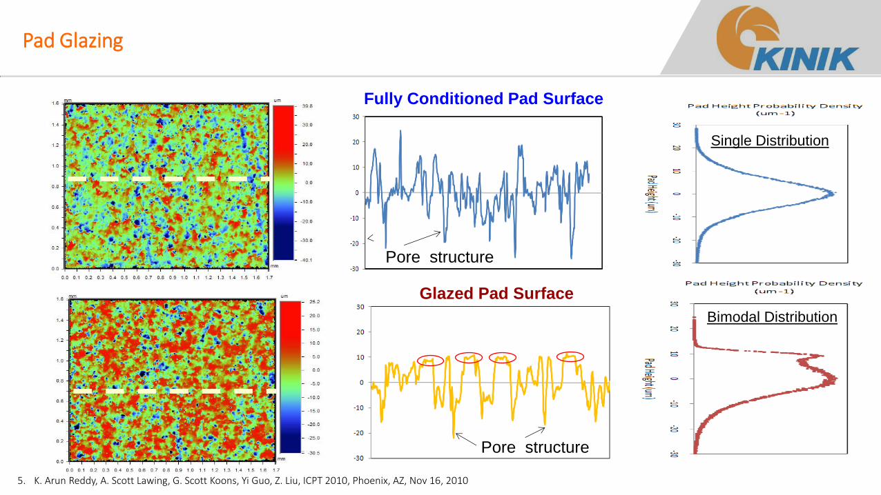
Glazed Pad Surface
Pad Glazing
Pore structure
Pore structure
Single Distribution
Bimodal Distribution
Fully Conditioned Pad Surface
5. K. Arun Reddy, A. Scott Lawing, G. Scott Koons, Yi Guo, Z. Liu, ICPT 2010, Phoenix, AZ, Nov 16, 2010
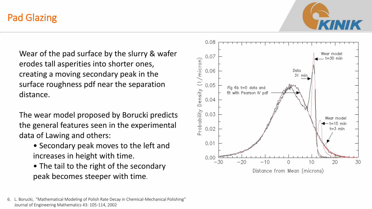
Pad Glazing
6. L. Borucki, “Mathematical Modeling of Polish Rate Decay in Chemical-Mechanical Polishing” Journal of Engineering Mathematics 43: 105-114, 2002
Wear of the pad surface by the slurry & wafer erodes tall asperities into shorter ones, creating a moving secondary peak in the surface roughness pdf near the separation distance. The wear model proposed by Borucki predicts the general features seen in the experimental data of Lawing and others:
• Secondary peak moves to the left and increases in height with time. • The tail to the right of the secondary peak becomes steeper with time.
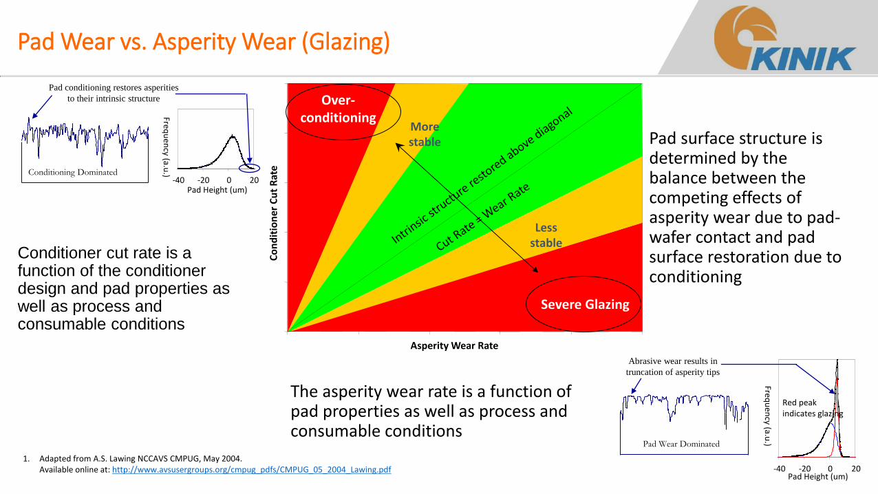
Pad Wear vs. Asperity Wear (Glazing)
The asperity wear rate is a function of pad properties as well as process and consumable conditions
Asperity Wear Rate
Co
nd
itio
ner
Cu
t R
ate
Over-conditioning
Severe Glazing
More stable
Less stable
Conditioning Dominated
Pad conditioning restores asperities
to their intrinsic structure
-40 -20 0 20 Pad Height (um)
Frequ
ency (a.u
.)
Pad Wear Dominated
Abrasive wear results in
truncation of asperity tips
-40 -20 0 20 Pad Height (um)
Frequ
ency (a.u
.)
Red peak indicates glazing
Conditioner cut rate is a function of the conditioner design and pad properties as well as process and consumable conditions
Pad surface structure is determined by the balance between the competing effects of asperity wear due to pad-wafer contact and pad surface restoration due to conditioning
1. Adapted from A.S. Lawing NCCAVS CMPUG, May 2004. Available online at: http://www.avsusergroups.org/cmpug_pdfs/CMPUG_05_2004_Lawing.pdf
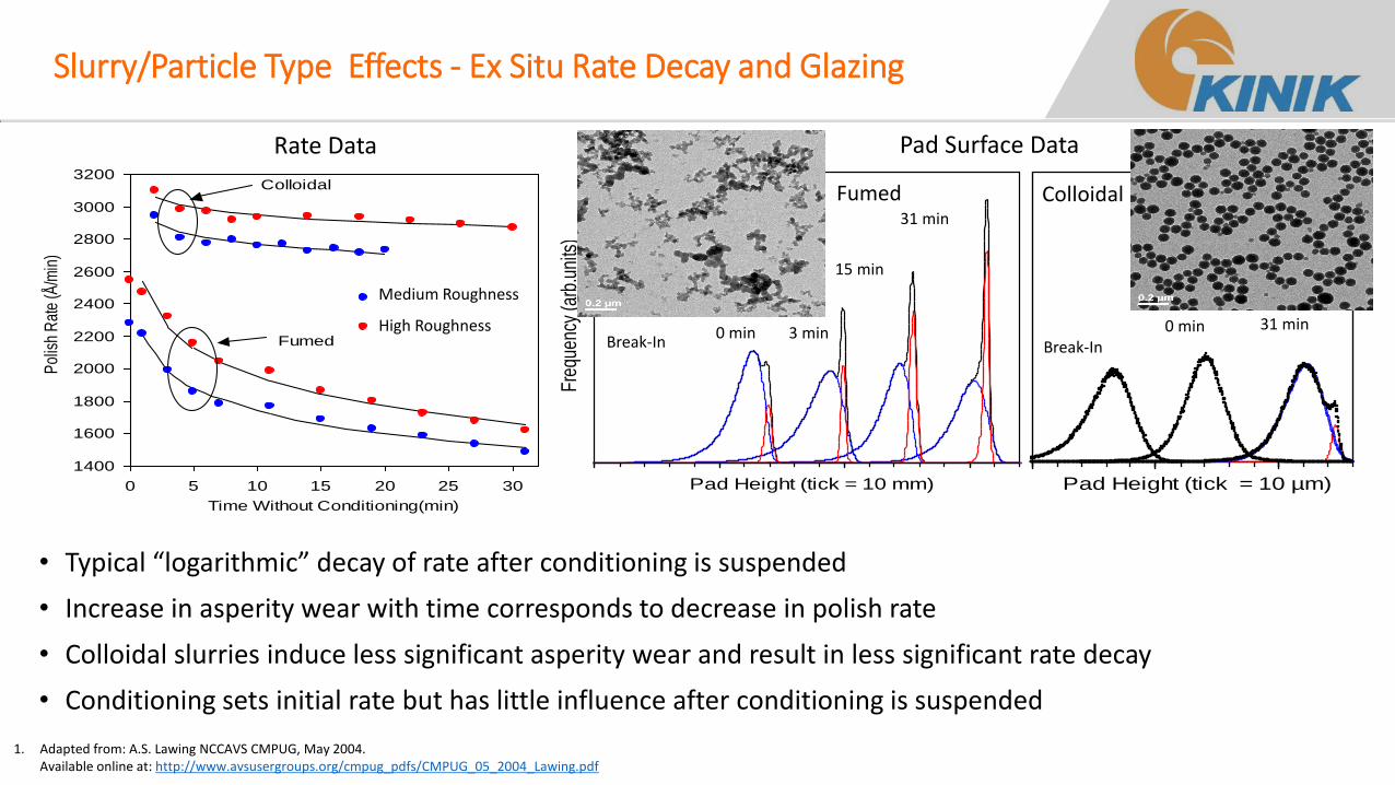
Slurry/Particle Type Effects - Ex Situ Rate Decay and Glazing
• Typical “logarithmic” decay of rate after conditioning is suspended
• Increase in asperity wear with time corresponds to decrease in polish rate
• Colloidal slurries induce less significant asperity wear and result in less significant rate decay
• Conditioning sets initial rate but has little influence after conditioning is suspended
1400
1600
1800
2000
2200
2400
2600
2800
3000
3200
0 5 10 15 20 25 30
Time Without Conditioning(min)
Pol
ish
Rat
e (Å
/min
)
Medium Aggressive
High AggressiveFumed
Colloidal
Pad Height (tick = 10 mm)
Freq
uenc
y (a
rb.u
nits
)
Pad Height (tick = 10 µm)
Fumed - Medium Colloidal
Break-In 0 min
3 min
15 min
31 min
Break-In 0 min 31 min
Rate Data Pad Surface Data
3 min
Fumed
1. Adapted from: A.S. Lawing NCCAVS CMPUG, May 2004. Available online at: http://www.avsusergroups.org/cmpug_pdfs/CMPUG_05_2004_Lawing.pdf
Medium Roughness
High Roughness
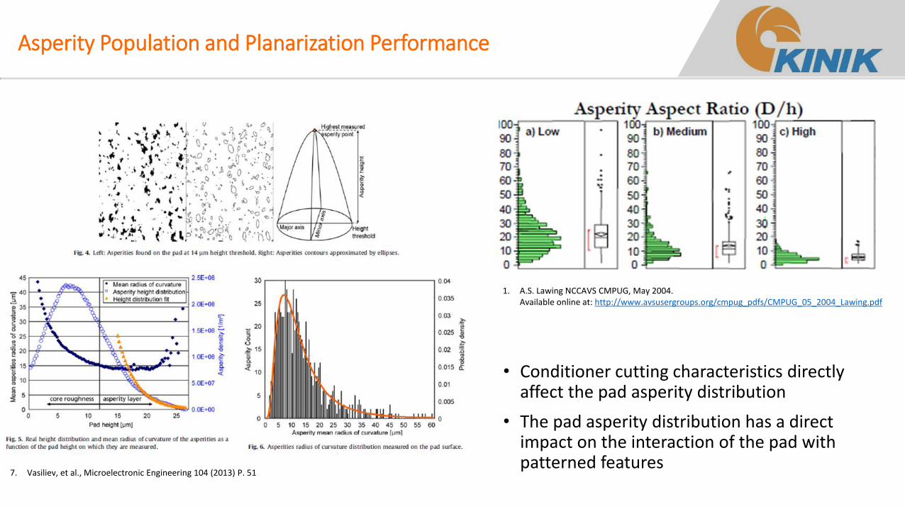
Asperity Population and Planarization Performance
7. Vasiliev, et al., Microelectronic Engineering 104 (2013) P. 51
• Conditioner cutting characteristics directly affect the pad asperity distribution
• The pad asperity distribution has a direct impact on the interaction of the pad with patterned features
1. A.S. Lawing NCCAVS CMPUG, May 2004. Available online at: http://www.avsusergroups.org/cmpug_pdfs/CMPUG_05_2004_Lawing.pdf
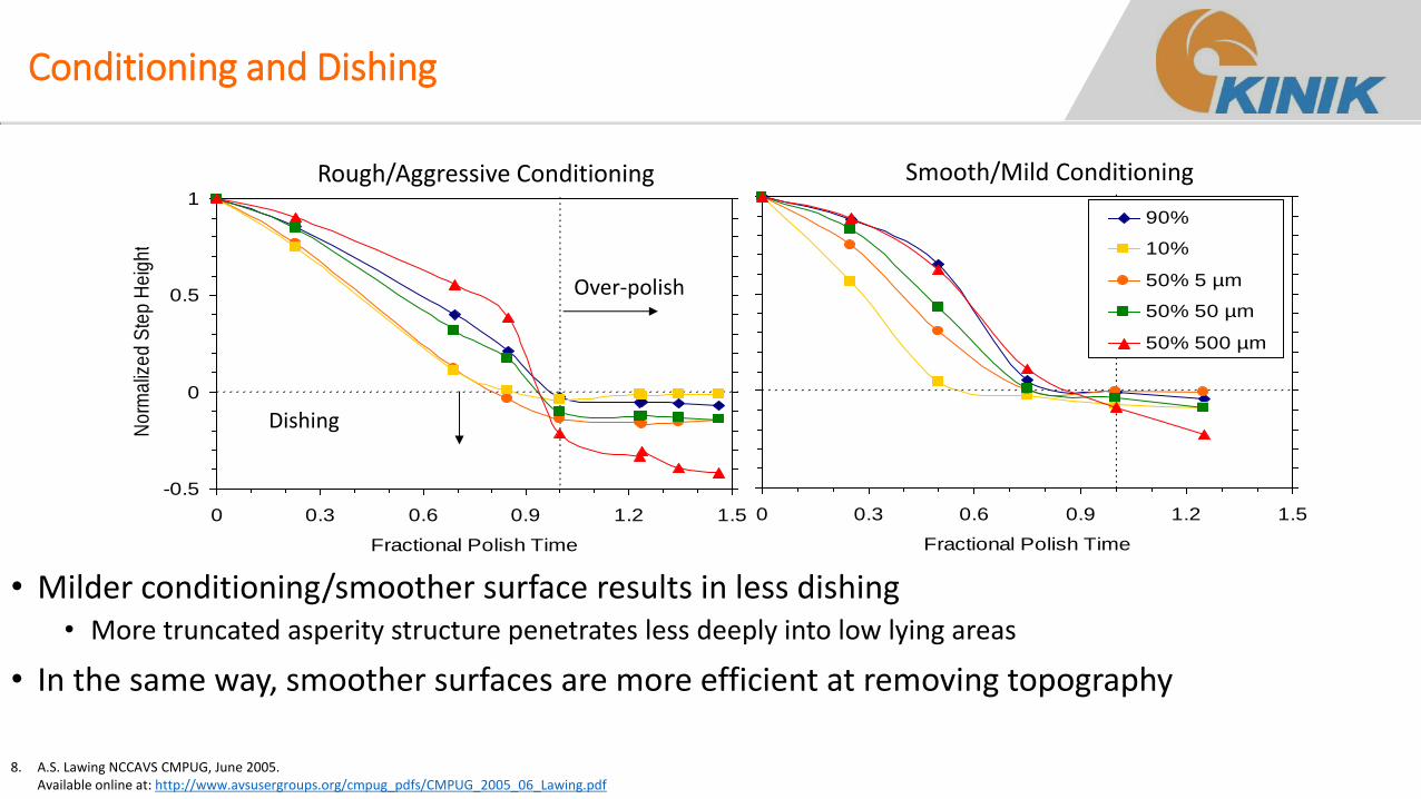
Conditioning and Dishing
-0.5
0
0.5
1
0 0.3 0.6 0.9 1.2 1.5
Fractional Polish Time
No
rma
lize
d S
tep
He
igh
t
-0.5
0
0.5
1
0 0.3 0.6 0.9 1.2 1.5
Fractional Polish Time
No
rma
lize
d S
tep
He
igh
t
90%
10%
50% 5 µm
50% 50 µm
50% 500 µm
Over-polish
Dishing
Rough/Aggressive Conditioning Smooth/Mild Conditioning
8. A.S. Lawing NCCAVS CMPUG, June 2005. Available online at: http://www.avsusergroups.org/cmpug_pdfs/CMPUG_2005_06_Lawing.pdf
• Milder conditioning/smoother surface results in less dishing • More truncated asperity structure penetrates less deeply into low lying areas
• In the same way, smoother surfaces are more efficient at removing topography
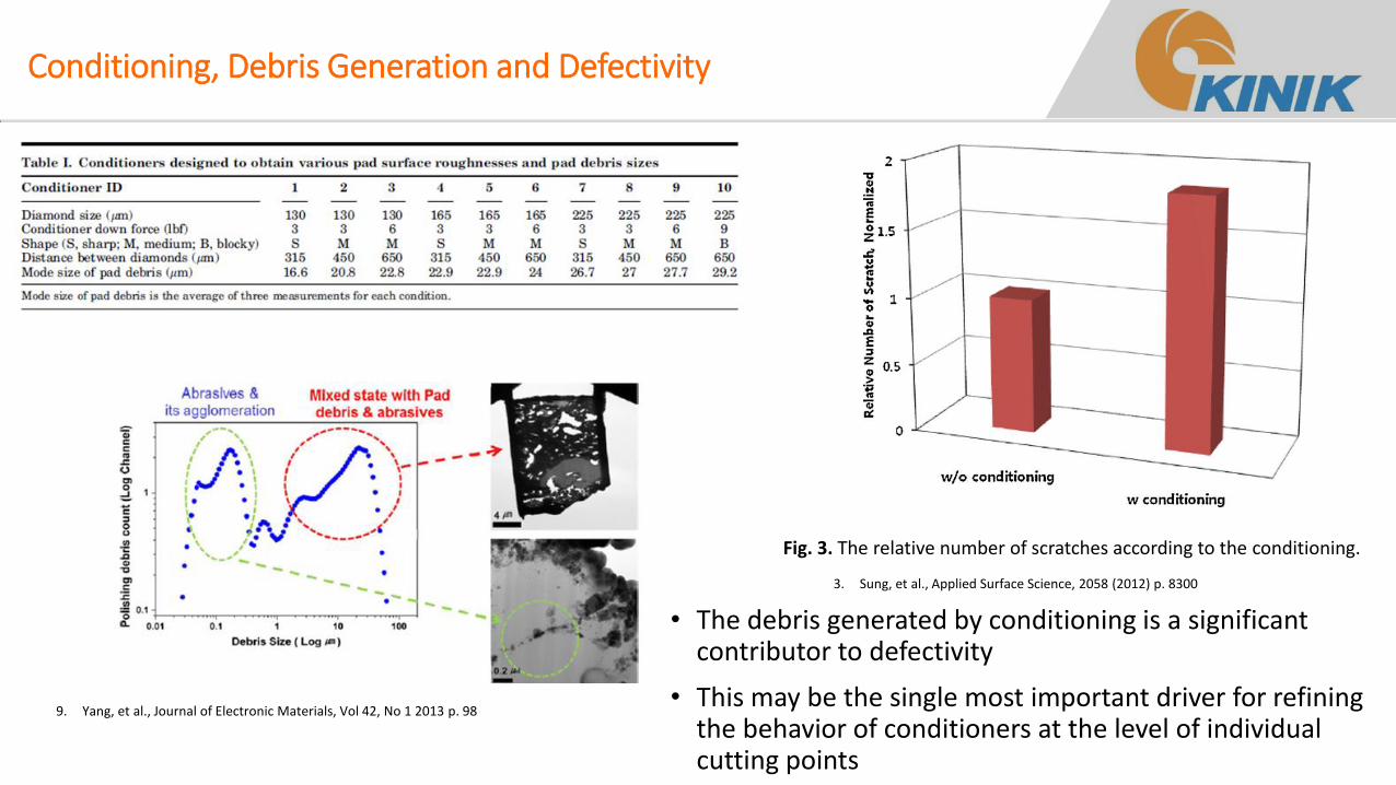
Conditioning, Debris Generation and Defectivity
9. Yang, et al., Journal of Electronic Materials, Vol 42, No 1 2013 p. 98
Fig. 3. The relative number of scratches according to the conditioning.
3. Sung, et al., Applied Surface Science, 2058 (2012) p. 8300
• The debris generated by conditioning is a significant contributor to defectivity
• This may be the single most important driver for refining the behavior of conditioners at the level of individual cutting points
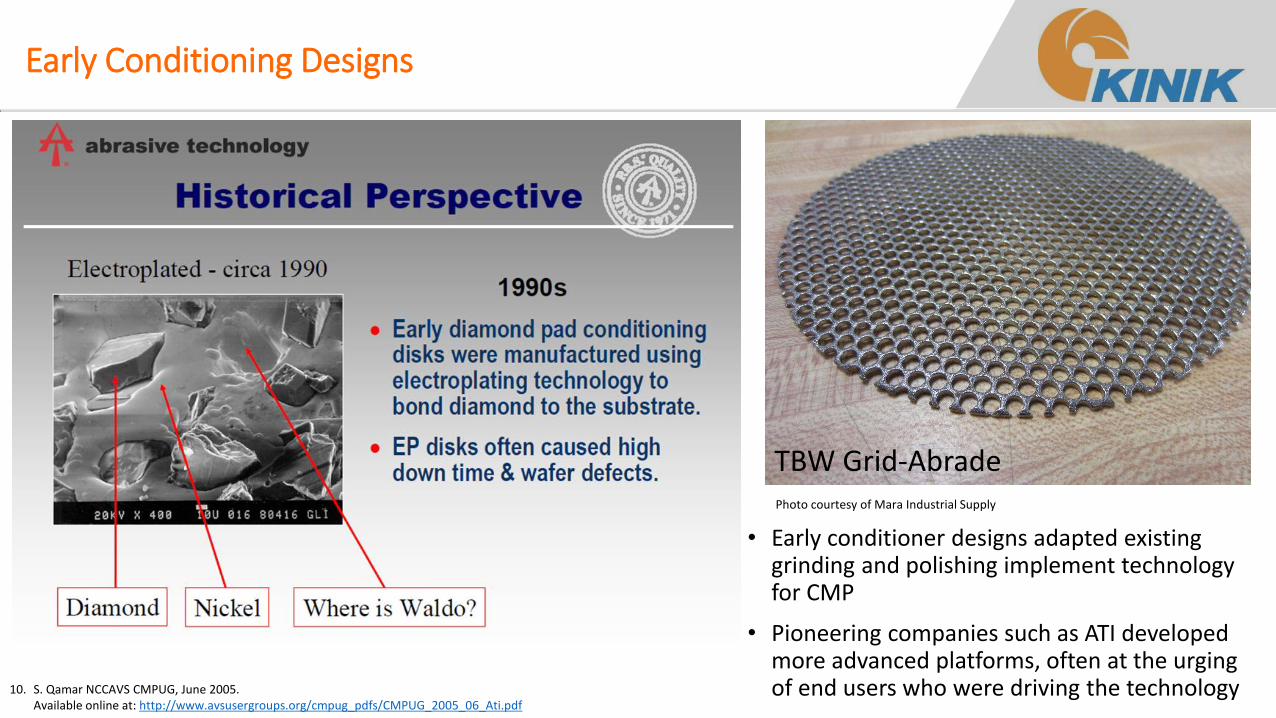
Early Conditioning Designs
10. S. Qamar NCCAVS CMPUG, June 2005. Available online at: http://www.avsusergroups.org/cmpug_pdfs/CMPUG_2005_06_Ati.pdf
TBW Grid-Abrade Photo courtesy of Mara Industrial Supply
• Early conditioner designs adapted existing grinding and polishing implement technology for CMP
• Pioneering companies such as ATI developed more advanced platforms, often at the urging of end users who were driving the technology
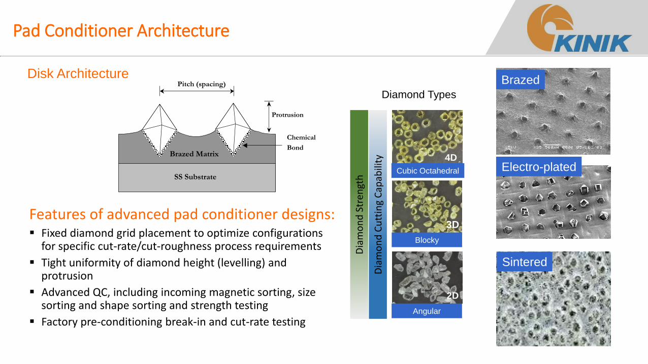
Pad Conditioner Architecture
SS Substrate
Brazed Matrix
Protrusion
Pitch (spacing)
Chemical
Bond
Features of advanced pad conditioner designs: Fixed diamond grid placement to optimize configurations
for specific cut-rate/cut-roughness process requirements
Tight uniformity of diamond height (levelling) and protrusion
Advanced QC, including incoming magnetic sorting, size sorting and shape sorting and strength testing
Factory pre-conditioning break-in and cut-rate testing
Disk Architecture
4D
Cubic Octahedral
3D
Blocky
2D
Angular
Diamond Types
Dia
mo
nd
Str
engt
h
Dia
mo
nd
Cu
ttin
g C
apab
ility
Brazed
Electro-plated
Sintered
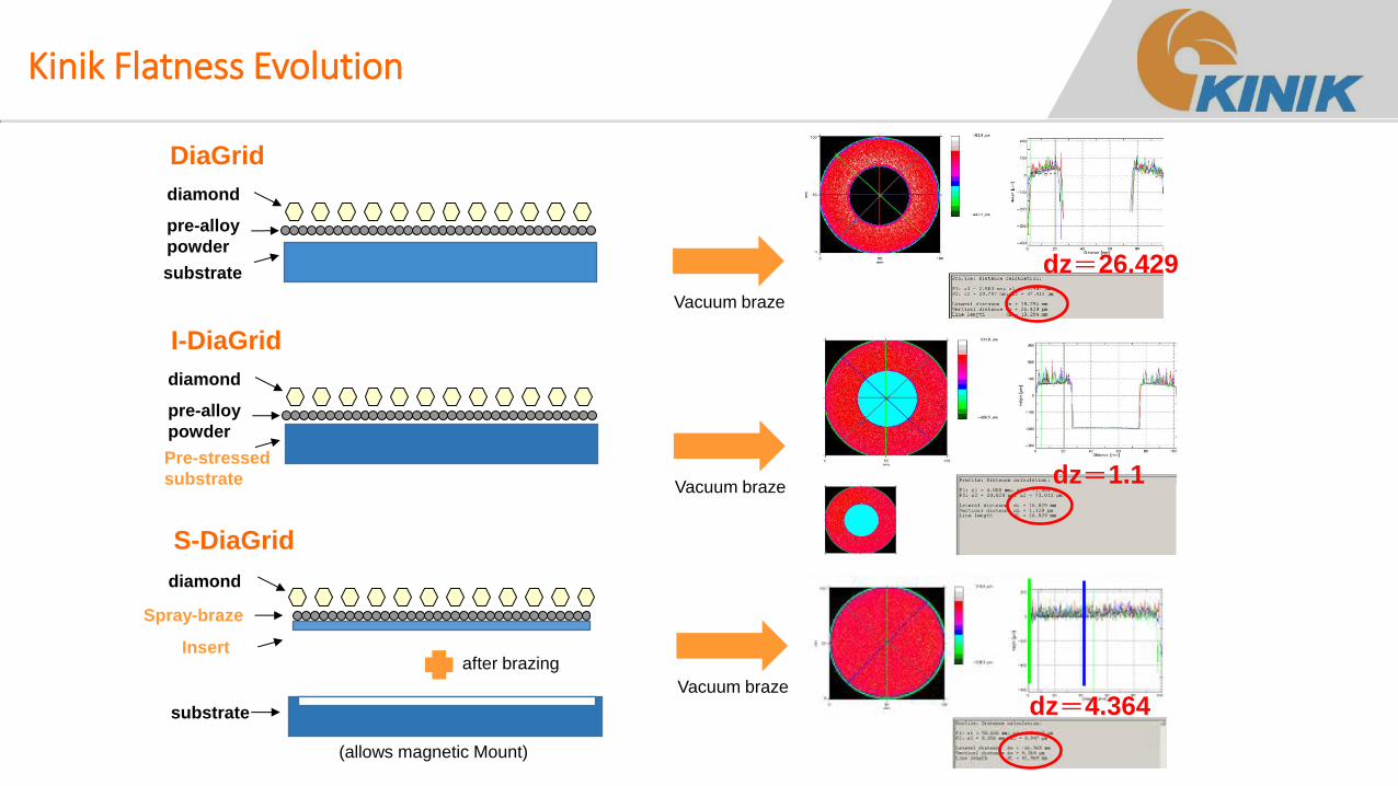
Kinik Flatness Evolution
DiaGrid
I-DiaGrid
S-DiaGrid
diamond
substrate
pre-alloy
powder
diamond
Pre-stressed
substrate
pre-alloy
powder
diamond
Insert
Spray-braze
substrate
after brazing
(allows magnetic Mount)
Vacuum braze
Vacuum braze
Vacuum braze
dz=1.1
dz=26.429
dz=4.364
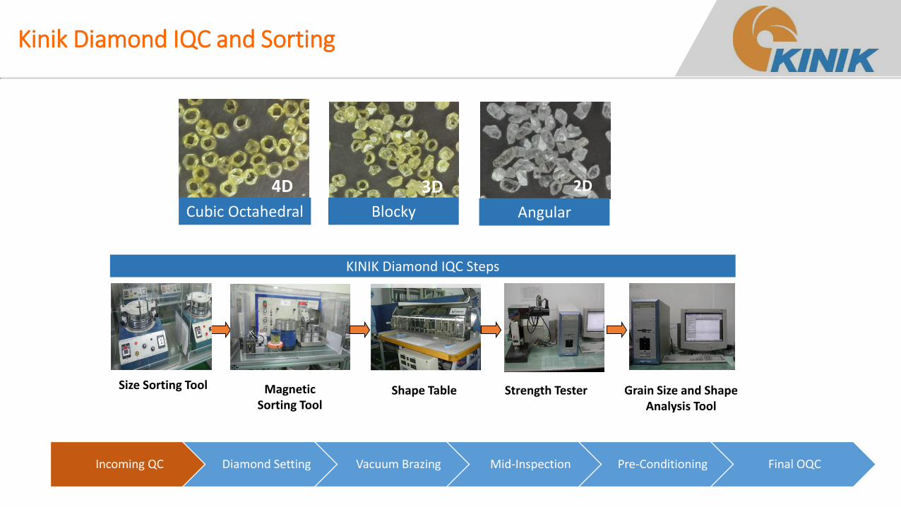
Kinik Diamond IQC and Sorting
Incoming QC Diamond Setting Vacuum Brazing Mid-Inspection Pre-Conditioning Final OQC
4D
Cubic Octahedral
3D
Blocky
2D
Angular
Size Sorting Tool Grain Size and Shape Analysis Tool
Shape Table Strength Tester
KINIK Diamond IQC Steps
Magnetic Sorting Tool
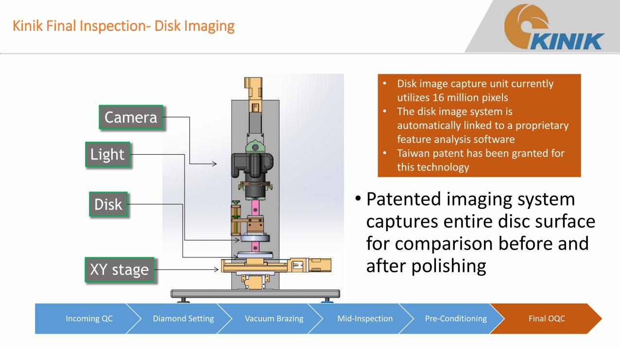
Kinik Final Inspection- Disk Imaging
Camera
Light
Disk
XY stage
Incoming QC Diamond Setting Vacuum Brazing Mid-Inspection Pre-Conditioning Final OQC
• Disk image capture unit currently utilizes 16 million pixels
• The disk image system is automatically linked to a proprietary feature analysis software
• Taiwan patent has been granted for this technology
• Patented imaging system captures entire disc surface for comparison before and after polishing
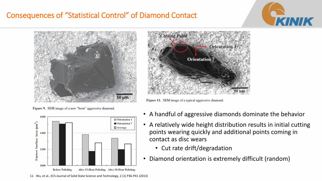
Consequences of “Statistical Control” of Diamond Contact
• A handful of aggressive diamonds dominate the behavior
• A relatively wide height distribution results in initial cutting points wearing quickly and additional points coming in contact as disc wears
• Cut rate drift/degradation
• Diamond orientation is extremely difficult (random)
11. Wu, et al., ECS Journal of Solid State Science and Technology, 2 (1) P36-P41 (2013)
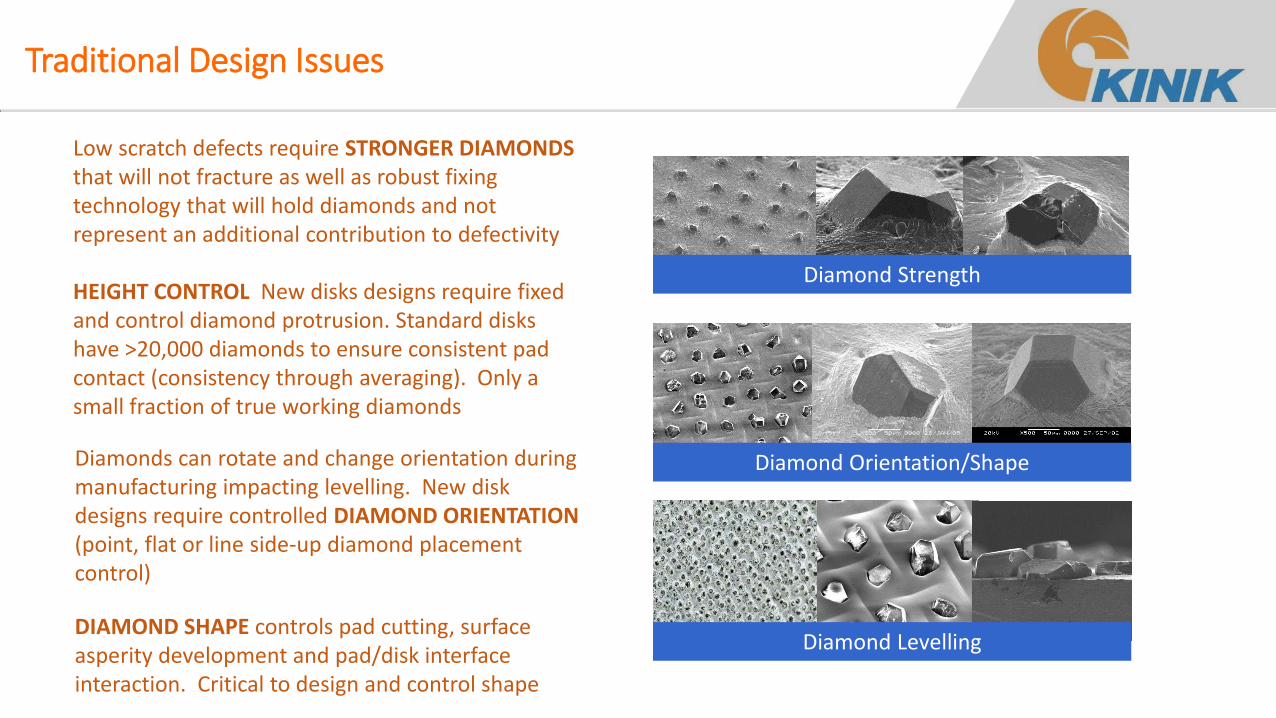
Traditional Design Issues
HEIGHT CONTROL New disks designs require fixed and control diamond protrusion. Standard disks have >20,000 diamonds to ensure consistent pad contact (consistency through averaging). Only a small fraction of true working diamonds
Diamonds can rotate and change orientation during manufacturing impacting levelling. New disk designs require controlled DIAMOND ORIENTATION (point, flat or line side-up diamond placement control)
Low scratch defects require STRONGER DIAMONDS that will not fracture as well as robust fixing technology that will hold diamonds and not represent an additional contribution to defectivity
Diamond Levelling DIAMOND SHAPE controls pad cutting, surface asperity development and pad/disk interface interaction. Critical to design and control shape
Diamond Orientation/Shape
Diamond Strength
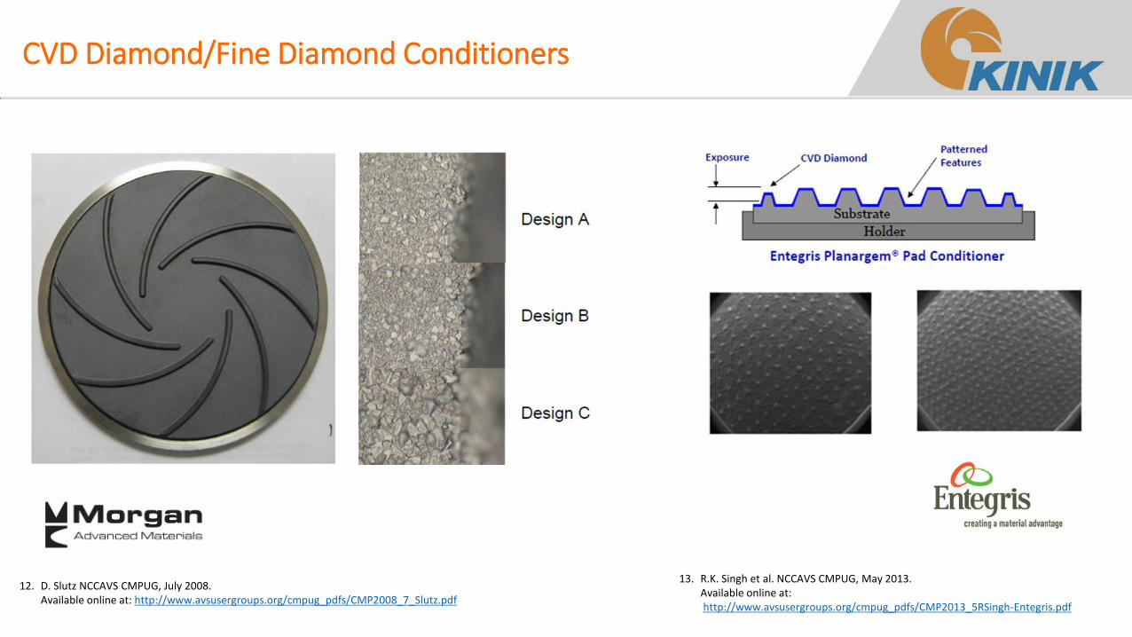
CVD Diamond/Fine Diamond Conditioners
12. D. Slutz NCCAVS CMPUG, July 2008. Available online at: http://www.avsusergroups.org/cmpug_pdfs/CMP2008_7_Slutz.pdf
13. R.K. Singh et al. NCCAVS CMPUG, May 2013. Available online at: http://www.avsusergroups.org/cmpug_pdfs/CMP2013_5RSingh-Entegris.pdf
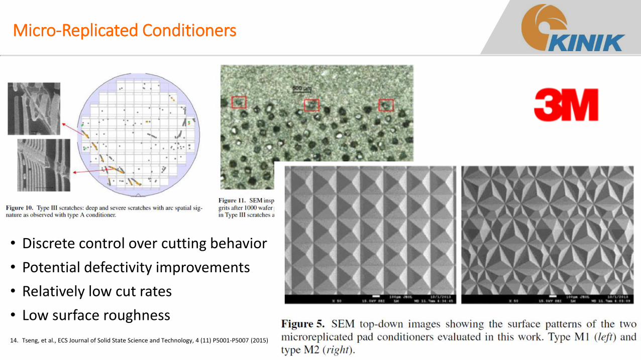
Micro-Replicated Conditioners
14. Tseng, et al., ECS Journal of Solid State Science and Technology, 4 (11) P5001-P5007 (2015)
• Discrete control over cutting behavior
• Potential defectivity improvements
• Relatively low cut rates
• Low surface roughness
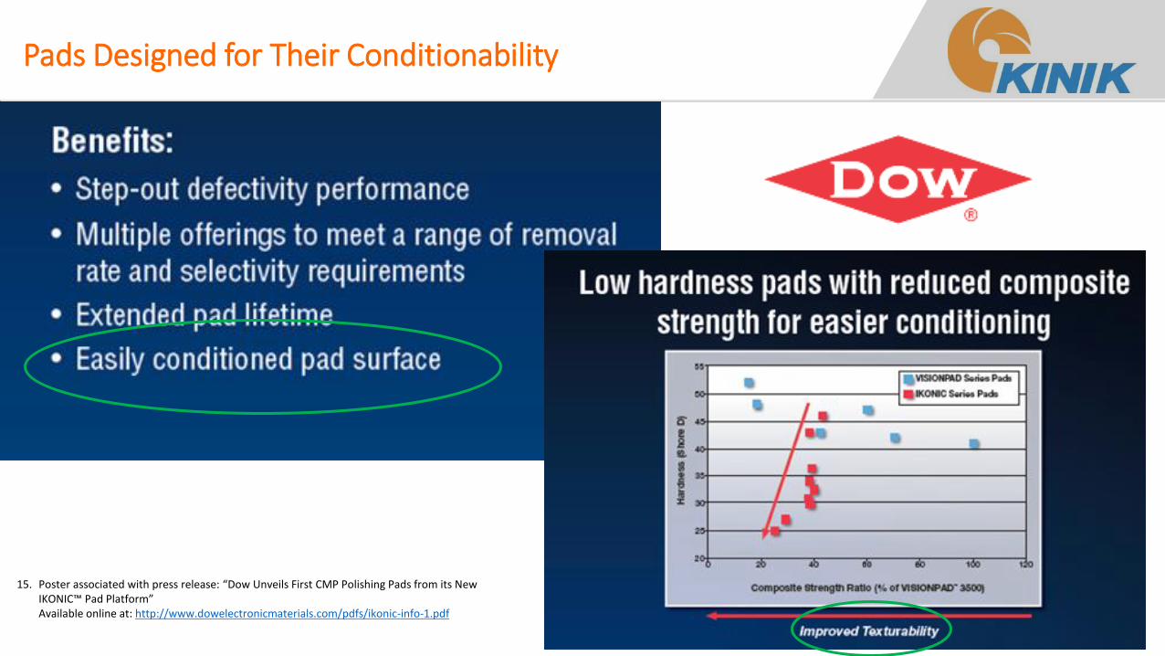
Pads Designed for Their Conditionability
15. Poster associated with press release: “Dow Unveils First CMP Polishing Pads from its New IKONIC™ Pad Platform” Available online at: http://www.dowelectronicmaterials.com/pdfs/ikonic-info-1.pdf
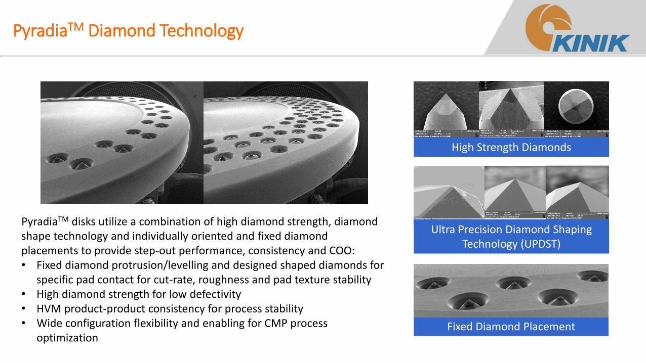
PyradiaTM Diamond Technology
PyradiaTM disks utilize a combination of high diamond strength, diamond shape technology and individually oriented and fixed diamond placements to provide step-out performance, consistency and COO: • Fixed diamond protrusion/levelling and designed shaped diamonds for
specific pad contact for cut-rate, roughness and pad texture stability • High diamond strength for low defectivity • HVM product-product consistency for process stability • Wide configuration flexibility and enabling for CMP process
optimization Fixed Diamond Placement
High Strength Diamonds
Ultra Precision Diamond Shaping Technology (UPDST)
Conventional
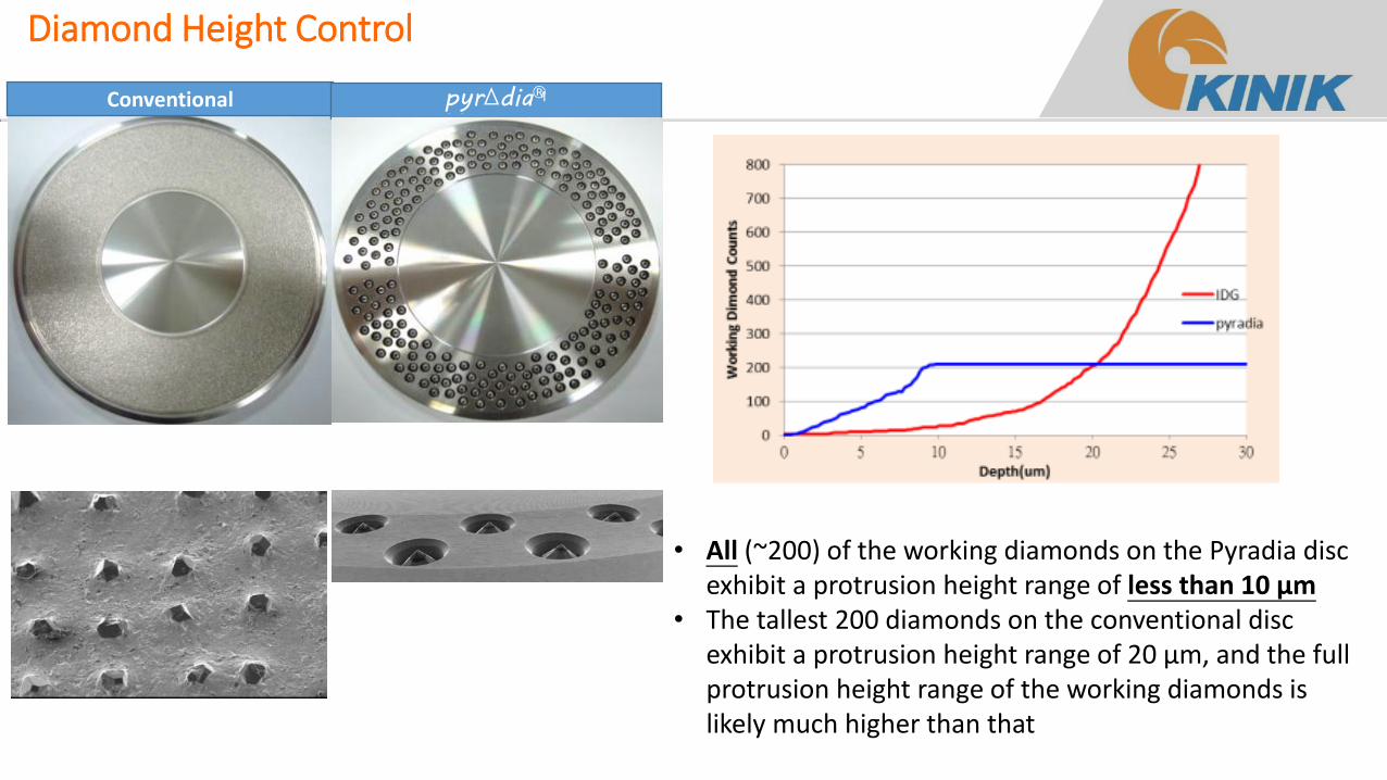
• All (~200) of the working diamonds on the Pyradia disc exhibit a protrusion height range of less than 10 µm
• The tallest 200 diamonds on the conventional disc exhibit a protrusion height range of 20 µm, and the full protrusion height range of the working diamonds is likely much higher than that
Diamond Height Control
pyr∆diaTM pyr∆dia®
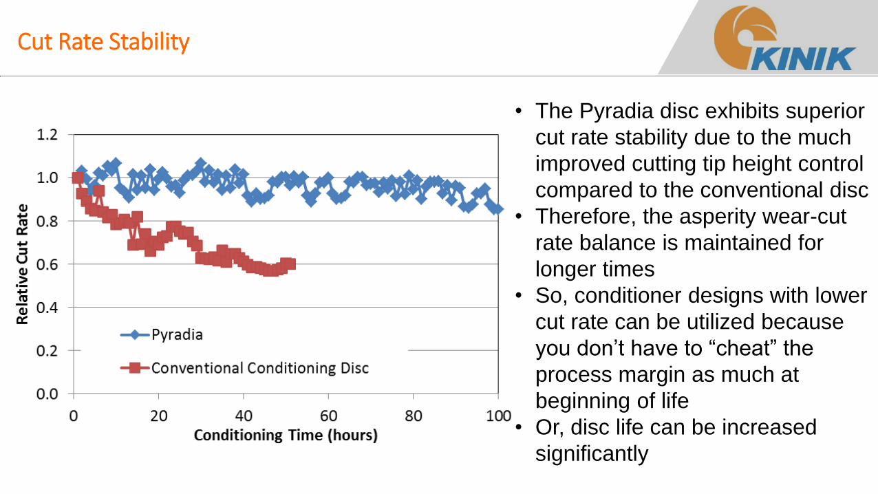
Cut Rate Stability
• The Pyradia disc exhibits superior
cut rate stability due to the much
improved cutting tip height control
compared to the conventional disc
• Therefore, the asperity wear-cut
rate balance is maintained for
longer times
• So, conditioner designs with lower
cut rate can be utilized because
you don’t have to “cheat” the
process margin as much at
beginning of life
• Or, disc life can be increased
significantly
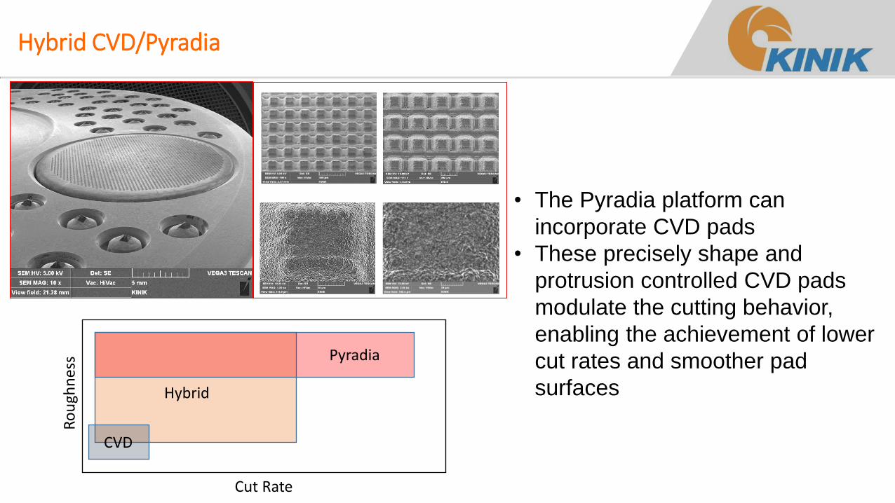
Hybrid CVD/Pyradia
• The Pyradia platform can
incorporate CVD pads
• These precisely shape and
protrusion controlled CVD pads
modulate the cutting behavior,
enabling the achievement of lower
cut rates and smoother pad
surfaces Hybrid
Pyradia
CVD
Ro
ugh
nes
s
Cut Rate
Summary
• Pad conditioning is critical to CMP performance both in terms of absolute metrics (polish rate, planarization, defectivity) and the stability of those metrics over time
• The surface texture of the pad can be analyzed, quantified, decoupled and tied to polish performance
• Pad conditioner cutting behavior drives the pad near surface
• Pad properties and conditioner design combine and interact to determine the overall structure of the pad surface
• These factors can be taken into account to drive and support next generation conditioner and process design
• As the process understanding of conditioning has evolved, so has the sophistication of conditioner hardware
• From the initial adoption of available technologies, to the development of specialized platforms and advanced statistical control
• State of the Art and Next Generation conditioning platforms aim to improve discrete control of cutting behavior
• Future advances will improve the synergy between pad, conditioner and process design