Embed Size (px)
Citation preview

Advances in Applied Superconductivity
leading Frontiers of particle accelerators and physics
Akira Yamamoto (KEK/CERN )
A Seminar at LAL, 21 Oct., 2016

Acknowledgmentsn I would thank
n M. Benedikt, L. Bottura and H. ten Kate of CERN, for their presentations at ASC2016 ( Denver) referred here.
n N. Ohuchi, K. Sasaki, M. Yoshida, T. Tomaru of KEK for their personal information,
n to prepare for this presentation.

Outlinen Introduction n Advances in particle accelerators
n Superconducting magnets and SRF
n Advances in particle detectors n Solenoid magnets in collider detectors n A unique application for scientific ballooning
n Recent advances in Japan

ISR
SppS
Tevatron
LHCp-p
HERA
PRIN-STANVEPP2ADONE
SPEAR
DORISCESR
PETRAPEP
TRISTANSLC LEPII
RHIC
LHClead-lead
0.1
1
10
100
1000
10000
100000
1960 1970 1980 1990 2000 2010 2020
Centre-of-m
asscollision
ene
rgy(GeV
)
Year
HadronCollidersElectron-ProtonCollidersLeptonCollidersHeavyIonColliders
Progress in Collider Accelerators Constructed and Operated
Colliderswithsuperconduc1ngarc
magnetsystem
Colliderswithsuperconduc1ngRF
system
Colliderswithsuperconduc1ngmagnet&RF
M. Benedikt

High Energy Colliders under study
100TeVpp→10-19mdiscoveryofnewpar7clesat10TeVmassscale
100TeV
M. Benedikt

Outlinen Introduction n Advances in particle accelerators
n Superconducting magnets and SRF n Advances in particle detectors
n Solenoid magnets in collider detectors n A unique application for scientific ballooning
n Recent advances in Japan
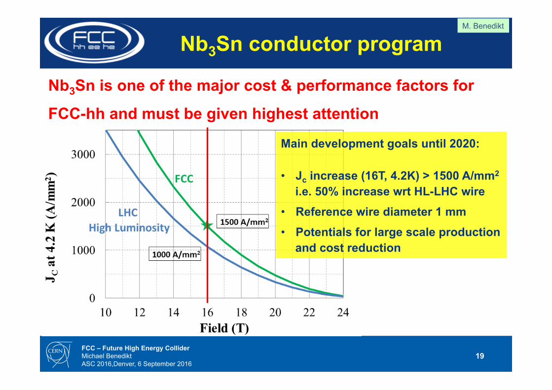
ProgressinPar1cle(Hadron)AcceleratorsbasedonSuperconduc1ngMagnetTechnology
Location Accelerator (proton)
Energy[TeV]
B Field [T] Operation
Fermilab Tevatron 2 x 0.9 4.0 1983-2011
DESY HERA 0.82 4.68 1990-2007
BNL RHIC 2 x 0.1 3.46 2000 -
CERN LHC 2 x 7 8.36 2009 -
CERN HL/HE-LHC, FCC
2 x 14 2 x 50
16 16 Study

Step 1: HL-LHC upgrade – ongoing
HL-LHCsignificantlyincreasesdataratetoimprovesta7s7cs,measurementprecision,andenergyreachinsearchofnewphysicsGainofafactor5inrate,factor10inintegraldatawrtini7aldesign
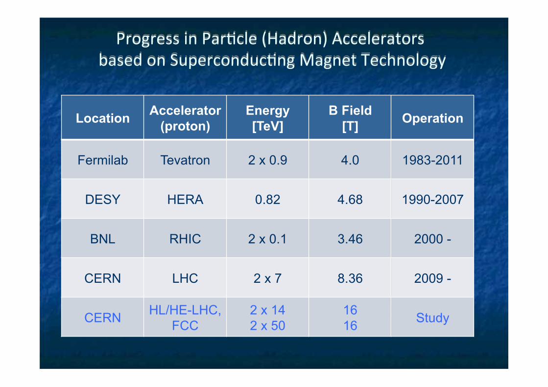
L. Rossi
High Luminosity LHC project scope
Morethan100newSCmagnets36largemagnetsinNb3Sn
PoweringviaSCLinksandHTSCurrentLeads
20newRFcavi1esNewtunnelandsurfaceinfrastructures
Newandupgradedcryoplants
L. Rossi

Superconductor performance at 4.2 K • magnets usually work in
boiling liquid helium, so the critical surface is often represented by a curve of current versus field at 4.2K
• niobium tin Nb3Sn has a much higher performance than NbTi
• but Nb3Sn is a brittle intermetallic compound with poor mechanical properties
1
10
100
1000
10000
0 10 20 30Field (T)
Crit
ical
cur
rent
den
sity
J c (
A m
m -2
)niobium titanium
niobium tin
Conventional magnet
• both the field and current density of both superconductors are way above the capability of conventional electromagnets�
NbTI� Nb3Sn�
M. Wison

11TdipoleinHL-LHC• CreatespaceinthedispersionsuppressorregionsofLHC,toinstalladdi7onal
collimatorsneededtocopewithbeamintensi1eslargerthannominal• ReplaceastandardMainDipolebyapairof11TDipolesproducingthesame
integratedfieldof119T·mat11.85kA
InterconnectSpaceforCollimator
11TdipolecoldmassBy-passcryostat 15660 mm
LS2
LS3
F. Savary

MBH (11T) dipole
5.5 m long coil
7000
8000
9000
10000
11000
12000
13000
14000
0 5 10 15 20 25 30 35
Quen
chcu
rrent(A
)
Quenchnumber
MBHSP101ThermalcycleSP101MBHSP102ThermalcycleSP102MBSP103MBHDP101ThermalcycleDP101
12T- Ultimate
11.2T- Nominal
12.37 T
By courtesy of F. Savary (CERN)
0.0
2.0
4.0
6.0
8.0
10.0
12.0
14.0
16.0
0 5 10 15
Ic [k
A]
Bp [T]
Ic (1.9K) REF - 5% (kA) Magnet Load Line Operational point
F. Savary

Reducingbeam-sizeatIPwithLargeApertureQuadrupoles
Smallerβ*⇒largerITaperture

LHC IR Quadruple with KEK-Fermilab Collaboration to be replaced

G. Chlachidze, S. Stoynev
MQXF quadrupole G. Ambrosio (FNAL),
P. Ferracin (CERN)

17 FCC – Future High Energy Collider Michael Benedikt ASC 2016,Denver, 6 September 2016
FCC SC main magnet options and requirements
LHC 27 km, 8.33 T 14 TeV (c.o.m.) 1300 tons NbTi
FCC-hh 80 km, 20 T
100 TeV (c.o.m.) 2000 tons HTS 8000 tons LTS
FCC-hh baseline 100 km, 16 T
100 TeV (c.o.m.) 10000 tons Nb3Sn
HE-LHC baseline 27 km, 16 T
26 TeV (c.o.m.) 2500 tons Nb3Sn
Geneva
PS
SPS
LHC
M. Benedict

18 FCC – Future High Energy Collider Michael Benedikt ASC 2016,Denver, 6 September 2016
parameter FCC-hh HE-LHC* (HL) LHC collision energy cms [TeV] 100 >25 14 dipole field [T] 16 16 8.3 circumference [km] 100 27 27
# IP 2 main & 2 2 & 2 2 & 2
beam current [A] 0.5 1.12 (1.12) 0.58
bunch intensity [1011] 1 1 (0.2) 2.2 (2.2) 1.15 bunch spacing [ns] 25 25 (5) 25 25 beta* [m] 1.1 0.3 0.25 (0.15) 0.55 luminosity/IP [1034 cm-2s-1] 5 20 - 30 >25 (5) 1 events/bunch crossing 170 <1020 (204) 850 (135) 27 stored energy/beam [GJ] 8.4 1.2 (0.7) 0.36 synchrotron rad. [W/m/beam] 30 3.6 (0.35) 0.18
*tentative
Hadron collider parameters M. Benedikt
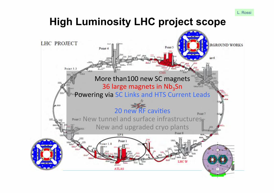
19 FCC – Future High Energy Collider Michael Benedikt ASC 2016,Denver, 6 September 2016
Nb3Sn conductor program
Nb3Sn is one of the major cost & performance factors for
FCC-hh and must be given highest attention
Main development goals until 2020: • Jc increase (16T, 4.2K) > 1500 A/mm2
i.e. 50% increase wrt HL-LHC wire • Reference wire diameter 1 mm • Potentials for large scale production
and cost reduction
M. Benedikt

20 FCC – Future High Energy Collider Michael Benedikt ASC 2016,Denver, 6 September 2016
16 T dipole options under consideration
Cos-theta
Blocks
Common coils
Down-selection of options end 2016 for more detailed design work
Swisscontribu7onviaPSI
Canted Cos-theta
1LOr3C-02, 2PL-01, 2LPo1A-10, 2LPo1D-02, 2LPo1D-03, 2LPo1D-05, 2LPo1D-07, 2LPo1D-08
M. Benedikt

High field magnets – Neolithic
Magnets with bore HL-LHC
LBNL HD1 (16 T at 4.2 K)
CERN RMC (16.2 T at 1.9 K)
Record fields for SC magnets in “dipole” configuration
L. Bottura

FCC CDR (EuroCirCol) propose a new energy frontier accelerator
16 T magnet model(s)
2016
2017
2018
2019
2020
2025
2030
2035
2040
2015
End of LHC useful life
20 T magnet model(s)
LHC Run-II provides results to define future HEP roadmap
(European Strategy 2018)
HL-LHC demonstrates large-scale use of Nb3Sn
FCC construction decision
Accelerator-grade HTS 5 T demo
12 T accelerator technology
16 T accelerator technology
L. Bottura

N. Ohuchi
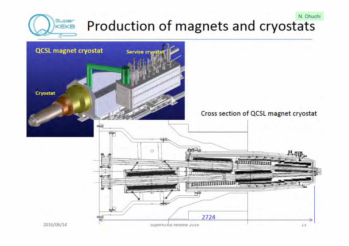
N. Ohuchi

N. Ohuchi

N. Ohuchi

Outlinen Introduction n Advances in particle accelerators
n Superconducting magnets and SRF n Advances in particle detectors
n Solenoid magnets in collider detectors n A unique application for scientific ballooning
n Recent advances in Japan

Progress in lepton Colliders �Great Steps with TRISTAN and LEP�

Progress in Particle (Lepton) Accelerators based on SRF Technology
Location Acc. Energy E [MV/m]
Freq. [GHz] Operation
KEK TRISTAN 2 x 30 5 0.5 1986-1995
CERN LEP 2 x 10⁵ 5 0.5 1989-2000
JLab CEBAF 6 7 1.3 1995~
KEK KEKB 8 5 0.5 1999~2007
DESY EXFEL* 14 24 1.3 construction
Fermilab PIP* 8 ~20 1.3 Plan
--- ILC* 2 x 250 31.5 1.3 Plan

main linacbunchcompressor
dampingring
source
pre-accelerator
collimation
final focus
IP
extraction& dump
KeV
few GeV
few GeVfew GeV
250-500 GeV
SRFTechnology
- ElectronandPositronSources(e-,e+):- DampingRing(DR):- RingtoMLbeamtransport(RTML):- MainLinac(ML):SCRFTechnology- BeamDeliverySystem(BDS)
SRF Technology

EuropeanXFELSRFbeingCompleted
1.3 GHz / 23.6 MV/m 800+4 SRF acc. Cavities 100+3 Cryo-Modules (CM)
Progress:2013:Construc1onstarted2015:SRFcav.(100%)completedCM(70%)progressed
FurtherPlan:2016:E-XFELacc.comple1on2016/E:E-XFELbeamtostartAcc.:~1/10scaletoILC-MLSRFsystem:~1/20scaletoILC-SRF
XFEL
DESY
XFELsite DESY
Media.xfel.au,Dec.2015
1kmSRFLinac
31
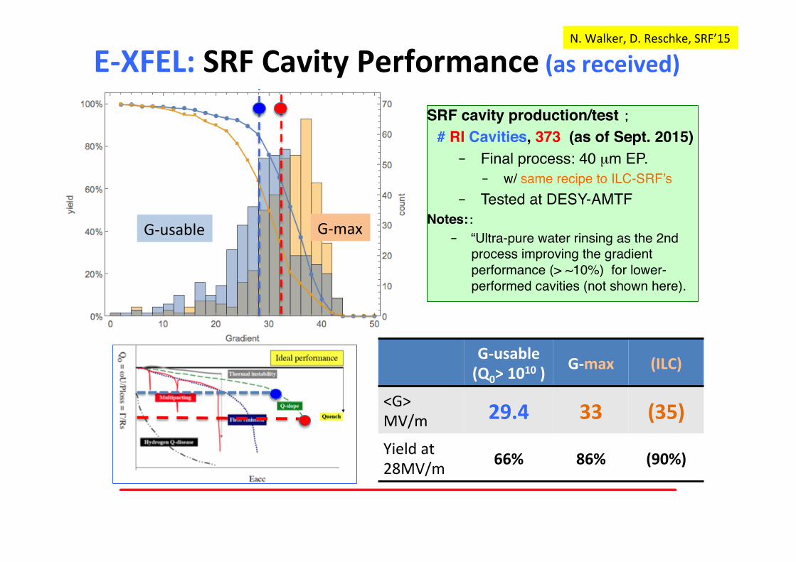
SRF cavity production/test ;
# RI Cavities, 373 (as of Sept. 2015) ‒ Final process: 40 µm EP.
‒ w/ same recipe to ILC-SRF’s ‒ Tested at DESY-AMTF
Notes::‒ “Ultra-pure water rinsing as the 2nd
process improving the gradient performance (> ~10%) for lower-performed cavities (not shown here).
E-XFEL:SRFCavityPerformance(asreceived)N.Walker,D.Reschke,SRF’15
G-maxG-usable
G-usable(Q0>1010)
G-max (ILC)
<G>MV/m 29.4 33 (35)Yieldat28MV/m 66% 86% (90%)

47 of 420 cavities of RI cavity production exceed 40 MV/m
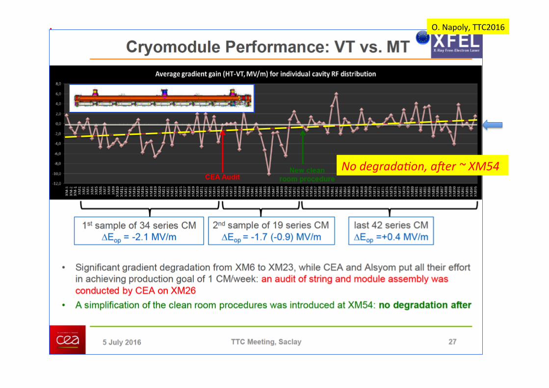
Nodegrada)on,a,er~XM54
O.Napoly,TTC2016

Fermilab:CM2reached<31.5MV/m>
CryomoduletestatFermilabreached<31。5>MV/m,exceedingILCspecifica1on
E.Harms,TTC2014
ILCMilestone31.5MV/m

KEK-STF: Cavity/CM Performance, and RF and Beam Test Preparation
FY14:CM1+CM2a(8+4)assemblyFY15:CavityindividuallytestedinCMRFpowersysteminprepara1onFY16:8-cavitystringtobeRFtestedFY17:BeamAccelera1onexpected(toreach>250MeV)
SRF cavity Gradient (MV/m) before/after CM Assembly
Module CM1a CM1b CM2a
Cav. # 1 2 3 4 5 6 7 8 9 10 11 12
V. Test (CW) 37 36 38 36 37 35 39 36 12 36 32 32
in CM (pulse) 39 37 35 36 26 16 26 32 18 34 33 32
Gradient stable Degraded Gradient stable
*<G>:30MV/m(12Cav.),35MV/m(best8)
Y.Yamamoto,E.Kako,H.Hayano

ILCAcc.DesignOverview(TDR)
e- Source
e+ Main Liinac
e+ Source
e- Main Linac
Item � Parameters �
C.M.Energy� 500GeV �
Length� 31km �
Luminosity� 1.8x1034cm-2s-1�
Repe77on� 5Hz �
BeamPulsePeriod� 0.73ms�
BeamCurrent� 5.8mA�
Beamsize(y)atFF� 5.9nm �
SRFCavityG.Q0�
31.5MV/mQ0=1x1010�main linacbunch
compressor
dampingring
source
pre-accelerator
collimation
final focus
IP
extraction& dump
KeV
few GeV
few GeVfew GeV
250-500 GeV
Nano-beamTechnology
SRFAccelera1ngTechnology
KeyTechnologies
PhysicsDetectors
Damping Ring

• Nano-beamTechnology:KEK-ATF2:FFbeamsize(v)of41nmat1.3GeV(togo37nmasaprimarygoal) FFbeamposi1onstabilityof67nm(limitedbymonitorresolu1on)
• SRFTechnology:SRFcavitygrad.inTDR:reachedG-max=37MV/mandanYieldof94%at>28MV/mBeamaccelera7on:DESY-FLASHandKEK-STFrealized9mA,and1msEuropeanXFEL:Cavityproduc1onatRI/EZ,100%(800+4)completed,<G>=~30MV/m.‒ Cryomodule(CM)assembly,100%(100+3)completed,<G>=~28MV/m.
» {lastCM,deliveredfromCEA-SaclaytoDESYon29July,2016}Fermilab:CMreachedtheILCgradientspecifica1on:G≥31.5MV/mKEK-STF2:Thebest8-cavitystringforbeamaccelera1on:G≥31.5MV/m.
• ADI:AcceleratorDesignandIntegra7onLCC-ILC:workingforfurtherrobustandcost-effec1vedesignandR&D
ProgressinAcc.KeyTechnologiesfortheILC

KEK-ILCAc7onPlanIssued,Jan.2016hhps://www.kek.jp/en/NewsRoom/Release/20160106140000/
ILCProgressandProspect
Pre-Preparation Stage Main Preparation Stage
present (we are here) P1 P2 P3 P4
ADI Establish main parameters Verify parameters w/ simulations
SRF Beam acc. with SRF cavity string,Cost Reduction R&D (proposed)
Demonstrate mass-production technology, stability, hub-lab functioning, and global sharing
Nano-beam Achieve the ILC beam-size goal Demonstrate the nanobeam size and stabilize the beam position
e+ Demonstrate technological feasibility Demonstrate both the undulator and e-driven e+ sources
CFS Pre-survey and basic design Geology survey, engineering design, specification, and drawings

New potential breakthrough: very high Q at very high gradients with low temperature (120C) nitrogen treatment
4/12/16Alexander Romanenko | FCC Week 2016 - Rome34
- Record Q at fields > 30 MV/m
- Preliminary data indicates potential 15% boost in achievable quench fields
- Can be game changer for ILC!
NewLowTNitrogenTreatmentforHigh-Qand–GstudiedanddemonstratedatFermilab
• Samecavity,sequen1allyprocessed,noEPinb/w
• Achieved:45.6MV/mQat~35MV/m:~2.3e10
0
100
200
300
400
500
600
700
800
900
1.00E‐10
1.00E‐09
1.00E‐08
1.00E‐07
1.00E‐06
1.00E‐05
1.00E‐04
1.00E‐03
1.00E‐02
1.00E‐01
4/12/2016 12:00
4/13/2016 0:00
4/13/2016 12:00
4/14/2016 0:00
4/14/2016 12:00
4/15/2016 0:00
4/15/2016 12:00
4/16/2016 0:00
4/16/2016 12:00
Temperature (°C)
Pressure (torr)
TE1PAV007 ‐ with caps ‐ Process12 April 2016 ‐ IB4 Furnace
Chamber Pressure
Cavity Temperature
800C 2 hrscooldown to 120C120C 48 hrs w N2 @ 25 mTorrcooldown
Rate of Rise:7.33E‐05 microns/min
A. Grassellino, S. Aderhold, TTC-2016
ILCProgressandProspect

AplanforILCCost-Reduc7onR&DinJapanandUSfocusingonSRFTechnology,in2~3years
Basedonrecentadvancesintechnologies;• Nbmaterialprepara1on
-w/op1mumRRRandcleansurface• SRFcavityfabrica1onforhigh-Qandhigh-G
-w/anewbakingrecipeprovidedbyFermilab
• Powerinputcouplerfabrica1on-w/new(lowSEE)ceramicwithoutcoa1ng
• Cavitychemicalprocess-w/ver1calEPandnewchemical(nonHF)solu1on
• Others
New potential breakthrough: very high Q at very high gradients with low temperature (120C) nitrogen treatment
4/12/16Alexander Romanenko | FCC Week 2016 - Rome34
- Record Q at fields > 30 MV/m
- Preliminary data indicates potential 15% boost in achievable quench fields
- Can be game changer for ILC!
ILCProgressandProspect
S.Michizono,S.Belomestnykh

Outlinen Introduction n Advances in particle accelerators
n Superconducting magnets and SRF n Advances in particle detectors
n Solenoid magnets in collider detectors n A unique application for scientific ballooning
n Recent advances in Japan
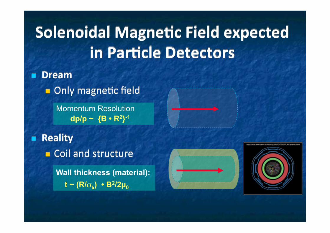
SolenoidalMagne7cFieldexpectedinPar7cleDetectors
n Dreamn Onlymagne1cfield
n Realityn Coilandstructure
Momentum Resolution dp/p ~ {B • R2}-1
Wall thickness (material): t ~ (R/σh) • B2/2µ0

History of Detector Solenoids

Technical Progress, since 1970~ : Al-soldered to NbTi/Cu ISR, CelloSecondary winding TPCAl co-extrusion w/ NbTi/Cu CDFInner winding Topaz, Thermo-siphon Aleph, Delphi2-layer-coil w/ grading Zeus, CleoHigh-str. Al. stab. ATLAS, BESSPure-Al strip Q. propagatorHybrid conductor CMSShunted w/ SUS mandrel CMD-2-----Radially self-supporting BESS-PolarNo outer support cylinder (for ballooning)
Technical Progress in Particle Detector Solenoid
Focusing on ATLAS-CS and BESS, in this talk

Issues and technical development in Thin Solenoid Magnets
n Thickness: t ∝ RB2/ (E/M) ∝ RB2 (γ / σ ) n High E/M (stored energy / coil-mass) n Light (low Z, γ) stabilizer (Cu à Al)
n Al provide long radiation length (Xo): (Cu) = 14 mm�à (Al) = 89 mmn Al provide high stability à high MQE (to be discussed in the next talk)
n High mechanical strength to be improved n High-strength Al stabilizer or reinforcement required n à Micro-alloying (Al + Si, Zn, Mg, Ni, …) + Cold-work hardening n à Reinforcement using hybrid configuration
n Quench safety: thermo-mechanical stability n Fast quench propagation and uniform energy absorption
n Pure-Al strip contributing fast thermal propagation n à Minimizing thermal stress/strain, above 80 K
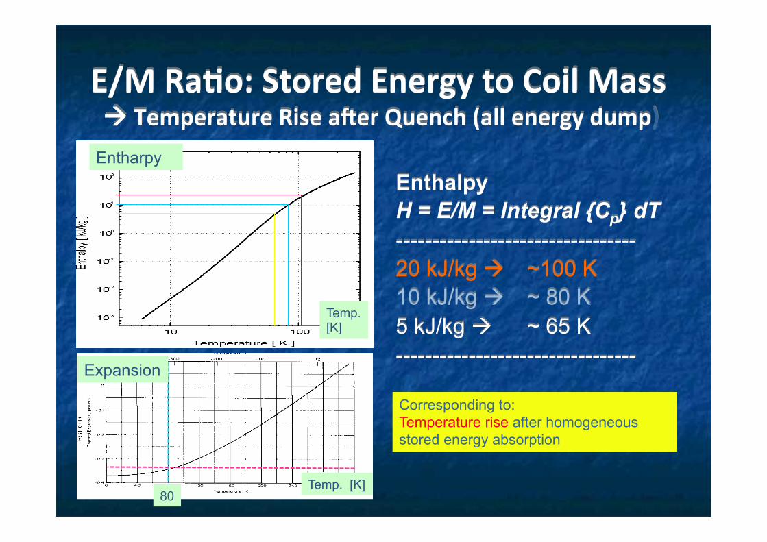
E/MRa7o:StoredEnergytoCoilMassàTemperatureRiseaperQuench(allenergydump)
Enthalpy H = E/M = Integral {Cp} dT --------------------------------- 20 kJ/kg à ~100 K 10 kJ/kg à ~ 80 K 5 kJ/kg à ~ 65 K --------------------------------- Corresponding to: Temperature rise after homogeneous stored energy absorption
80
Expansion
Entharpy
Temp. [K]
Temp. [K]

Al-stabilized Conductor Technology reached with
LHC-ATLAS and – CMS n Reinforcement of Al
n with keeping low resistivity
n Uniform reinforcement n Micro-alloying and cold work n ATLAS-CS
n Hybrid reinforcement n Welding Al-Alloy with pure-Al n CMS

Micro-alloying with pure-Al with ATLAS-CS and BESS
Additve metal A Dens. Solubility resistivity contribution (in solution / crystal.) [g/cm3] [w-%] [10-12 Ωm/wppm]
Solid solution: Si 28 2.6 1.65 0.7 0.088 Zn 65 7.1 83 @ 400C 0.10 0.023 Crystallization / Precipitation: Ni 59 8.8 0.05 @640C 0.81 0.061
<0.006 @<500C
Ni:BestreinforcementwithkeepingLowresis1vity.
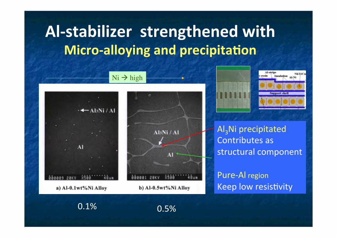
Al3NiprecipitatedContributesasstructuralcomponentPure-AlregionKeeplowresis1vity
Ni à high
0.1% 0.5%
Al-stabilizerstrengthenedwithMicro-alloyingandprecipita7on

E/M: Progress and Future
0
5
10
15
0.1 1 10 100 1000 104
WASABESS
CMD-2D0
ZEUS
VENUS
TOPAZCLEO-II
BABAR
CDF
BELLEDELPHI
ALEPHH1
SDC-proto
ATLAS-CS (2 T)
CMS (4 T)under construction
BessP-Proto
E/M
(k
J/kg
)
Stored energy (MJ)
BessP (1 .05T) C
CMS (4T) w/ half energy extracted
Full E absorbed Half E absorbed
Future
Progress

Progress in Thickness of Solenoid Coil Wall in terms of Radiation Length [X]
0
0.5
1
1.5
2
2.5
3
0 1 2 3 4 5 6 7 8
Thickness [X]Transparency [X]
Thic
knes
s in
Rad
iatio
n Le
ngth
[X]
B2 x R [Tesla2 • m]
ATLAS
SDC-PT
ZEUS
BESSWASA
VENUS
ALEPH
H1
DELPHI
TOPAZCELLO
CDF
D0
PEP4
CLEO-II
BESS-Polar
Thinness not required Thinness required

Progress of Al-Stabilizer Superconductor in Colliding-Detector Magnets
0
50
100
150
200
250
300
TOPAZ SDC ATLAS/CS CMS-overall
YS(MPa) @4.2K
RRR/100

Development to further optimize “Strength” and “RRR” for future Detectors
Rein-force
Feature Al Y. S. (MPa)
Full cond. Y.S.
Full cond. RRR
ATLAS-CS
Uniform Ni-0.1% Al 110 MPa 146 MPa 590
CMS Hybrid Pure-Al & A6082-T6
26 / 428 258 (1400)
Future
Hybrid Ni-Al & A6082-T6
110 / 428 300 400
Future Hybrid Ni-Al & A7020-T6
110 / 677 400 400
CMS structure and ATLAS-CS alloy may be combined

Future Prospects for Collider Detector Solenoids
n Magnet Parameters n Field: 4 ~ 6 Tesla n Diameter: 4 ~ 8 m n E/M: 10 ~ 12 (< 15) kJ/kg
n Reinforcement n Target:
Y.S.(0.2%) = 400 MPa RRR = 400
n Issue: quench safety n Energy Extraction n Uniform E. Absorption
n Fast Q. propagation, n Quench back
ATLAS CS
Bess P CMS
Improved CMS
050
100150200250300350400450500
0 400 800 1200 1600
RRR
Equ
ival
ent y
ield
str
engt
h /M
Pa
Sgobba et al. (MT-19)
ILC: SiD ILD FCC (Courtesy, H. ten Kate)

Outlinen Introduction n Advances in particle accelerators
n Superconducting magnets and SRF n Advances in particle detectors
n Solenoid magnets in collider detectors n A unique application for scientific ballooning
n Recent advances in Japan

Scientific Objectives
Cosmic-ray Antiparticles provide important information on …
Elementary particle phenomena in the early universe
Fluxes are extremely small
Fundamental data of Cosmic-ray
Matter/Antimatter symmetry, SUSY darkmatter, Primordial Black hole, etc.
Production, propagation Solar modulation Interaction in the atmosphere
No positive signals before late 1970’s.
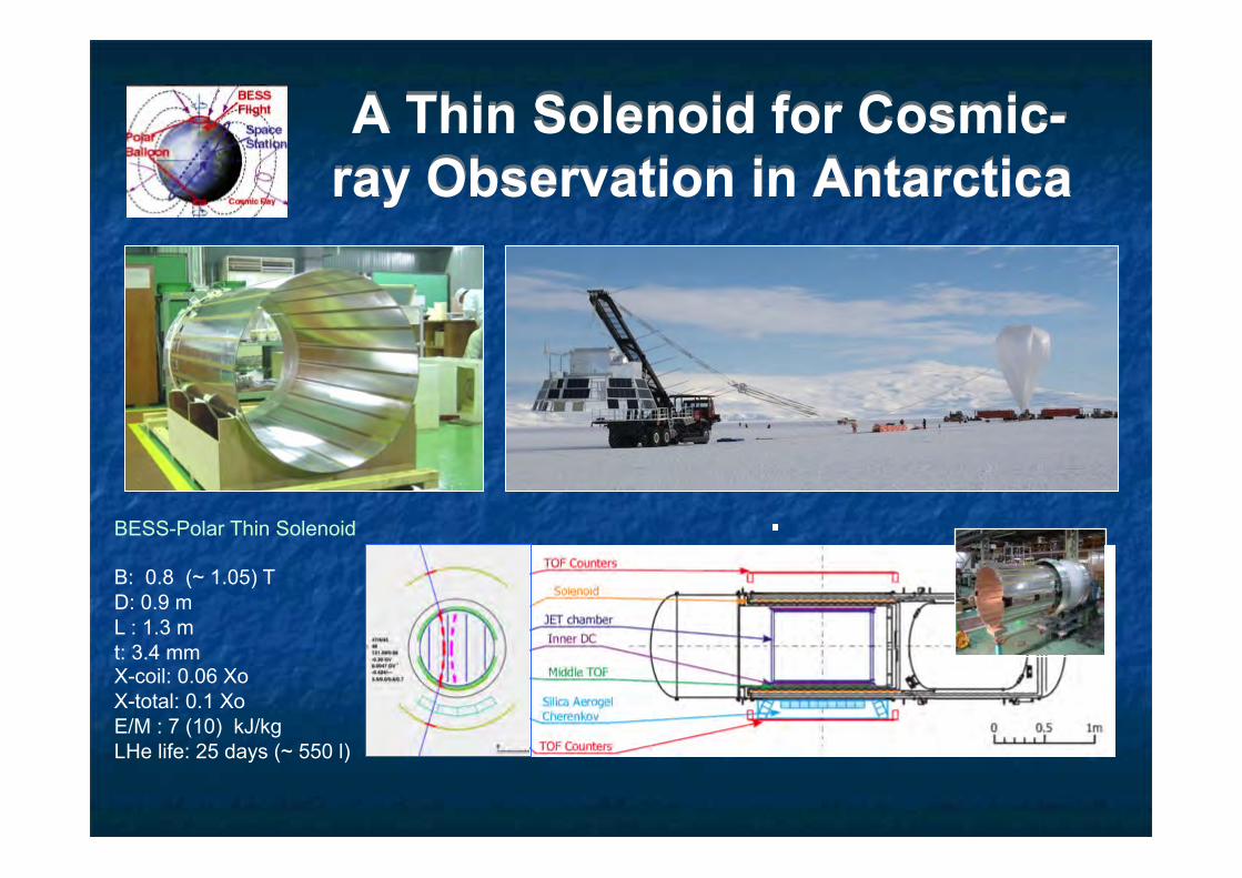
A Thin Solenoid for Cosmic-ray Observation in Antarctica
BESS-Polar Thin Solenoid B: 0.8 (~ 1.05) T D: 0.9 m L : 1.3 m t: 3.4 mm X-coil: 0.06 Xo X-total: 0.1 Xo E/M : 7 (10) kJ/kg LHe life: 25 days (~ 550 l)

Williams Field,McMurdo, in Antarctica 12/23 2007
Scientific Ballooning of BESS Detector at Antarctica - for Cosmic-Ray Observation -

End of BESS-Polar II Flight
• Flight termination January 20, 2008 ~30 days • Location 83 ° 51.23’ S, 73° 5.47’ W
• On West Antarctic ice sheet - 225 nm from Patriot Hills Camp, 185 nm from AGO-2, 357 nm from South Pole • Data successfully recovered February 3, 2008!

Outlinen Introduction n Advances in particle accelerators
n Superconducting magnets and SRF n Advances in particle detectors
n Solenoid magnets in collider detectors n A unique application for scientific ballooning
n Recent advances in Japan


PrimaryProtonBeamLineforJPARCNeutrinoExperiments

Superconduc7ngCombinedFunc7onMagnets�
ORDipole
Quadrupole Combined
x
By
Δx
BD
Dipole: 2.6 TQuadrupole: 19 T/mPeak Field: 4.2 T
grad
grad
grad
)(
QB
x
xxQ
xQBB
D
Dy
−=Δ
Δ−=
×+=

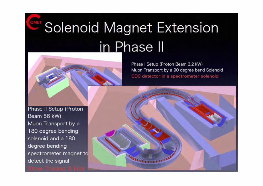
COMETExperiment
• J-PARCE21• 8GeVx7µA• stoppingµ-àMuonic
atom
nucleus�
µ-�
µ− + (A,Z)→νµ + (A,Z −1)
nuclear muon capture�decay in orbit�
µ− → e−νν
µ− + (A,Z)→ e− + (A,Z)µàe conversion�
( ) ( )( )NN
eNNNeNBʹ→Γ
→Γ=→ −−
νµµ
µ
Detect monoenergetic electrons from µ-e conversion
Physics Reach: Br<10-16 à 2x10¹⁸ muon stops
à 1011 µ-/sec


KeyIssue
• Radia1ontoleranceofmagnetmaterials
• Organicmaterial– Strength– Outgas
• Metal– Electricalconduc1on– Thermalconduc1on
• Radioac1va1onofHe
MARS2010+nuc.lib.
Nuclear Heating : >100W Peak dose rate in Al : ~1MGy Neutron fluence : >1021 n/m2
1022 1020 1018 1016 1014 1012 101010241026
n/m2
Peak: 3~5x10²¹ n/m2


muong-2/EDMmeasurements
⎥⎥⎦
⎤
⎢⎢⎣
⎡⎟⎟⎠
⎞⎜⎜⎝
⎛+×+
×⎟⎟⎠
⎞⎜⎜⎝
⎛
−−−−=
cEB
cEaBa
me
!!!
!!!!
βηβ
γω µµ 21
12
( )⎥⎦⎤
⎢⎣
⎡ ×+−= BBame !!!!
βη
ω µ 2
In uniform magnetic field, muon spin rotates ahead of momentum due to g-2 = 0
ω = −
em
aµB+η
2
β ×B+Ec
#
$%
&
'(
)
*+
,
-.
BNL E821 approachγ=30 (P=3 GeV/c)
J-PARC approach E = 0 at any γ
Proposed at J-PARC with 0.1ppm precision
general form of spin precession vector:
Continuation at FNAL with 0.1ppm precision
Anomalous magnetic moment (g-2) aµ= (g-2)/2 = 11 659 208.9 (6.3) x 10-10 (BNL E821 exp) 0.5 ppm 11 659 182.8 (4.9) x 10-10 (standard model) Δaµ= Exp - SM = 26.1 (8.0) x 10-10 3σ anomaly
from T. Mibe


BNLE821Superconduc1ngMagnet
ToroidalField
DipoleField
B=0B=1.5T
µStorageRingOrbit
µInjec7onOrbit
SCCoil
SCLamina7on
YokeofDipoleRingMagnet
RingSCCoilCross-Sec1onViewofStorageRing

Resonant Laser Ionization of Muonium (~106 µ+/s)
Graphite target (20 mm)
3 GeV proton beam ( 333 uA)
Surface muon beam (28 MeV/c, 4x10⁸/s)
Muonium Production (300 K ~ 25 meV⇒2.3 keV/c)
Silicon Tracker
66 cm
Super Precision Storage Magnet (3T, ~1ppm local precision)
from T. Mibe

Features in
KAGRA Underground
Cryogenic Mirror System
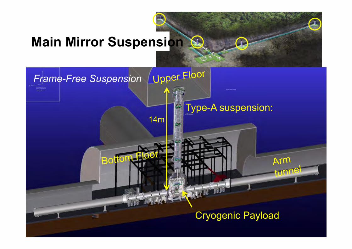
Upper Floor
Bottom FloorArm tunnel
14m
We excavate upper-floors and vertical holes for Vibration Isolation System. Base of the VIS is put on the upper-floor
Type-A suspension: 4-stage GAS filters @ room temperature
Cryogenic Payload
Main mirror parts
Frame-Free Suspension
Main Mirror Suspension
Type-A: Takahasi-san’s talk

Cryogenic Payload CryostatUnder developing in KEK and ICRR
Platform
Marionette & Recoil mass
Intermediate mass & recoil mass
Mirror & Recoil mass Prototype Cryo-Payload
Type-A
Cryogenics Talks -> Kumar, Miyamoto, Ushiba and Craig

KAGRA CryogenicsCryostat assembly
KAGRA cryostat
Vibration-Free cryocooler
Thermal radiation reduction by cryogenic “black” pipe
6N Al thermal conductor

Hoshikawa et al. ICEC-ICMC 2012
Size effect dominates conductivity of 6N Al thin wire at low temp.
Bulk Φ1.0mm Φ0.15mm
6N ~22,000 ~14,000 ~4,000
5N ~6,000 ~5,000 ~2,700
4N ~390 ~390 -
Estimated RRR
by Sakakibara
Es1matedthermalconduc1vityof6NAlw/Φ0.15mmisabout17,000,whichisabout1.51meslargerthanthatof5NAl.
Very soft thermal conductor