Embed Size (px)
Citation preview
Chinese Journal of Aeronautics, (2016), 29(2): 305–315
Chinese Society of Aeronautics and Astronautics& Beihang University
Chinese Journal of Aeronautics
REVIEW ARTICLE
Advances and trends in plastic forming technologies
for welded tubes
* Corresponding authors. Tel.: +86 29 88460212 805 (M. Zhan),
+86 29 88495632 (H. Yang).E-mail addresses: [email protected] (M. Zhan), gkyike@163.
com (K. Guo), [email protected] (H. Yang).
Peer review under responsibility of Editorial Committee of CJA.
Production and hosting by Elsevier
http://dx.doi.org/10.1016/j.cja.2015.10.0111000-9361 � 2015 The Authors. Production and hosting by Elsevier Ltd. on behalf of CSAA & BUAA.This is an open access article under the CC BY-NC-ND license (http://creativecommons.org/licenses/by-nc-nd/4.0/).
Zhan Mei *, Guo Kun, Yang He *
State Key Laboratory of Solidification Processing, School of Materials Science and Engineering,Northwestern Polytechnical University, Xi’an 710072, China
Received 29 June 2015; revised 31 July 2015; accepted 7 September 2015Available online 2 November 2015
KEYWORDS
Constraint effects;
Deformation coordination;
Finite element modeling;
Forming;
Forming limit;
Inhomogeneous deforma-
tion;
Material characteristics;
Welded tube
Abstract With the implementation of environmental protection, sustainable development and
conservation-oriented policies, components and parts of thin-walled welded tubes have gained
increasing application in the aircraft and automotive industries because of their advantages: easily
achieving forming and manufacturing process at low cost and in a short time. The current research
on welded tube plastic forming is mainly concentrated on tube internal high-pressure forming, tube
bending forming, and tube spinning forming. The focuses are on the material properties and char-
acterization of welded tubes, finite element modeling for welded tube forming, and inhomogeneous
deformation behavior and the mechanism and rules of deformation coordination in welded tube
plastic forming. This paper summarizes the research progress in welded tube plastic forming from
these aspects. Finally, with a focus on the urgent demand of the aviation, aerospace and automotive
industries for high-strength and light-weight tubes, this paper discusses the development trends and
challenges in the theory and technology of welded tube plastic forming in the future. Among them,
laser tailor-welded technology will find application in the manufacture of high-strength steel tubes.
Tube-end forming technology, such as tube flaring and flanging technology, will expand its appli-
cation in welded tubes. Therefore, future studies will focus on the FE modeling regarding how to
consider effects of welding on residual stresses, welding distortions and microstructure, the inhomo-
geneous deformation and coordination mechanism of the plastic forming process of tailor-welded
tubes, and some end-forming processes of welded tubes, and more comprehensive research on the
forming mechanism and limit of welded tubes.� 2015 The Authors. Production and hosting by Elsevier Ltd. on behalf of CSAA & BUAA. This is an
open access article under the CC BY-NC-ND license (http://creativecommons.org/licenses/by-nc-nd/4.0/).
1. Introduction
Compared with seamless tubes, welded tubes have advantages,
such as low production cost, high production efficiency,stable quality and variety, etc. With the implementation ofenvironmental protection, sustainable development and
306 M. Zhan et al.
conservation-oriented policies and the rapid development oflightweight structure forming manufacturing technology inthe aviation, aerospace and automotive industry, all types of
thin-wall welded tube parts and components are findingincreasingly extensive application.1–4 Especially in the aviationindustry, the tubing system is the core part of the aircraft.
Because of high material utilization rate, high production effi-ciency, and the properties of expanding and bending forminghaving little difference with seamless tube, welded tube is find-
ing wide application in aircraft environmental control anddrain line system. From the perspective of plastic forming,welded tube plastic forming belongs to the category of inho-mogeneous materials forming. The welded tube forming pro-
cess is similar to that of homogeneous tubes with wrinkling,cracking and other possible defects, while inhomogeneousmaterials and the performance of the parent metal, the weld
seam (weld line or weld bead) and the heat-affected zone(HAZ) of welded tubes lead to a complicated nonlinear mate-rials problem. The width of the weld seam and the HAZ and
their positions in the plastic forming process will result in acomplicated geometrical nonlinear problem. Material and per-formance differences among the weld seam, the HAZ and the
parent metal in the plastic forming process may also lead to acomplex contact with the tool and die and boundary nonlinearconditions. These nonlinear problems and their couplingeffects enhance the restriction of the weld (including the weld
seam and the HAZ) on the plastic forming quality of weldedtubes and make the plastic forming quality and forming per-formance/forming limit of welded tubes more sensitive to the
rules of constraints and deformation coordination among theweld seam, the HAZ and the parent metal. When the effectof inhomogeneous deformation among these zones is so strong
that they cannot deform in a coordinated fashion, defects suchas wrinkling and fracture may occur. Furthermore, thesedefects will constrain the normal plastic forming process of
welded tubes and the improvement in their forming perfor-mance. When each zone of the welded tubes can be deformedin a coordinated fashion, it is likely that the plastic formingprocess can be carried out smoothly, thereby improving the
forming quality of the welded tubes and fully exploiting thetubes’ deformation potential and improving their forming per-formance. These characteristics make the plastic forming
behavior of welded tubes different from those of homogeneoustubes. Therefore, it is important to perform research on weldedtube plastic forming theory and technology. This research will
provide a practical engineering theory basis for improving thequality of plastic forming of welded tubes and for exploringthe deformation potential of these tubes. It is significant andimportant for improving the level and capability of the high-
quality, low-cost, and short-cycle manufacturing technologyof welded tubes.
To date, the welded tube plastic forming research mainly
concentrates on three aspects, including internal high pres-sure forming, bending forming and spinning forming. Thefocus is on material properties and the characterization of
welded tubes, finite element modeling for welded tube form-ing, and inhomogeneous deformation behavior in weldedtube plastic forming and the mechanism and rules of
deformation coordination. Based on these aspects, this papersummarizes the research progress in welded tube plasticforming.
2. Material properties and constitutive modeling of welded tubes
Different welding technologies and processes will produceweld seams and HAZs with different appearances, sizes and
mechanical properties. This has a significant effect on theforming performance. Therefore, it is necessary to performresearch on welded tube performance and its characterization.
2.1. Weld characteristics of welded tubes
The appearance, size, mechanical properties and plastic form-
ing performance of the weld line and the HAZ are closelyrelated to the welding process, the speed, the temperature,the extrusion force and the thickness of the tube. Through met-allographic analysis and tensile testing, Chen5 investigated the
mechanical non-uniformity of a 304 (SUS304) austenitic stain-less steel welded joint of tailor-welded tubes that were madeusing tungsten inert gas (TIG) welding technology. He ana-
lyzed the variations and differences in the microstructure andmechanical properties of different zones of welded joints andascertained that the width of the weld was approximately
5 mm, and divided the welded joints into four regions, includ-ing parent metal, HAZ, fusion zone (or in some cases only afusion line) and weld seam. Khalfallah6 ascertained that theweld seam width of a low-carbon steel S235JR tube welded
by high-frequency induction welding was approximately1 mm and that the width of each HAZ was approximately2 mm. The weld region in their study was characterized by
much higher hardness (approximately HV= 198) than thatof the parent metal (approximately HV= 115). The yieldand tensile strength stresses of the weld specimen were higher
than those of the parent metal, whereas the strain hardeningexponent and the uniform elongation were lower for specimenscontaining the weld than those of the parent metal.6 Ghoo
et al.7 and Panda et al.8 also obtained similar findings. Yanget al.9 ascertained that the weld width of a QSTE340 weldedtube produced by resistance welding was 4 mm and the widthof each HAZ was 6 mm by analyzing the weld joint
microstructure and microhardness distribution. For high-frequency electric resistance welding (HF-ERW)10 and extru-sion welding11, the weld is always funnel-form. Ren et al.12
observed the weld shape to be like a typical drum by meansof microhardness distribution and microstructure analysis.They found that the difference among the parent material,
the HAZ and the fusion zone was apparent and determinedthat the weld seam width of 60 mm � 4.0 mm (d � t:d-tubeoutside diameter, t-wall thickness) and 78 mm � 2.7 mmQSTE340 HF ERW tubes were both 0.4 mm and the width
of the HAZ of both tubes was 2.4 mm. Li et al.13 used tensiletests and microhardness tests to study the mechanical perfor-mance of a CP3 pure titanium thin-walled welded tube which
would be used in the drain line system of a civil aircraft. Theirresults show that compared with the parent metal, the yieldstrength and tensile strength of the weld were higher, but the
elongation of the weld was obviously lower, and a large hard-ness gradient appeared in the HAZ. Ren14 also obtained sim-ilar conclusions in the research on QSTE340 steel welded
tubes. A large number of studies show that welding caused achange in the hardness of the weld area. For example, in laserwelding, the weld area hardness increased by 50%15 to
Advances and trends in plastic forming technologies for welded tubes 307
250%16. In most cases, the weld hardness increased by approx-imately 120%17.
2.2. Material modeling of welded tubes
The material properties of the weld seam and the HAZ have aclose relationship with the constitutive model of welded tubes.
Therefore, accurate constitutive modeling of the welding seamand HAZ is necessary for evaluating the welded tubes’ plasticformability through theory and finite element analysis (FEA).
There are four main methods for determining the materialproperties and constitutive relationship of the weld seam andthe HAZ of welded tubes.
The first method is to obtain the material properties of theweld seam and the HAZ through uniaxial tensile testing ofstandard specimen or non-standard small specimens madeonly of the weld seam and the HAZ18,19. In this method, the
results obtained from using a non-standard specimen are dif-ferent from those using a standard specimen. This is becauseas the specimen size increases, the resistance tensile stress of
the weld is weakened; thus, the material properties of the weldand the HAZ are particularly sensitive to the specimen size20.When the relative size of the weld on the specimen cross sec-
tion increases, the stress–strain curve of the specimen tendsto be closer to the stress–strain curve of the weld seam, somany researchers choose to use small specimens or micro-specimens to determine the material properties of weld
tubes21,22. However, it is difficult to cut the specimen whichcontains only the weld or the HAZ because of the narrowwidth of the welding seam and the HAZ and their irregular
cross sectional shape. Davies et al.23 showed that the plasticdeformation ability of the tensile specimen decreases as theproportion of the weld in the cross section of the specimen
increases by tensile testing different sizes of samples. Thismeans that the results obtained by this method have a greatdegree of dispersion.
The second method is to use an empirical formula based onmicrohardness; i.e., the material properties of the weld and theHAZ are determined according to the microhardness distribu-tion of the weld and its surrounding area, and, using the
directly proportional relationship between the flow stress andmicrohardness, the material properties of the weld and HAZare determined.24 The microhardness method is simple, conve-
nient, and fast; it does not cause damage to the specimen. Andthis method is often used for obtaining weld joint materialproperties. However, this method neglects the effect of the
welding method and welding parameters on the weld proper-ties, and there is no mature hardness criterion for the widthof the weld seam and HAZ.
The third method is commonly used in obtaining the weld
joint material properties and constitutive relationship basedon the rule of mixtures.25–27 This method uses a mixture of ten-sile specimens that include the weld and the surrounding mate-
rial. Then, based on the strain mixture rule of the weld seam,the parent metal and the HAZ, the constitutive relation of theweld and HAZ can be determined. This method is an indirect
method for obtaining the characteristics of the weld material,avoiding the disadvantages of the first method. When adoptingthe rule of mixtures to confirm the plastic constitutive relation-
ship of the weld material, the cross-sectional size must be accu-rately determined. Because there are no distinct boundaries
among the weld bead, the HAZ and the parent metal in themacrostructure, it is difficult to distinguish between them.20
Furthermore, during the preparation of the mixed specimen
according to the standard sample requirements, it is inevitablethat some HAZ and parent metal will be included in the mixedspecimen. Thus, the properties determined from the tensile test
of the mixed specimen are not only those of the weld seam andHAZ but also partly those of the parent metal. In view of theabove shortcomings, Zhan et al.20 proposed a microhardness
measurement method using cross-sectional samples of the tubeto truly represent the microhardness distribution characteris-tics along the thickness direction throughout the weld zone,HAZ and parent metal. They also proposed a new method
for establishing the constitutive relation of inhomogeneousmaterials based on the rule of mixtures and subdividing theHAZ into strips. This modified rule of mixtures diminished
the effects of the width of a mixed specimen on the flowstress–strain to some degree, and it could accurately and con-tinuously reveal the variation in flow stress across the HAZ.
Using this method, a more precise constitutive model of aQ215 welded tube was obtained by Zhan et al.20 Using thismethod, Ren et al.28 established a high-precision material con-
stitutive model of a QSTE340 welded tube.The fourth method is the digital image correlation (DIC)
method. This method was initially proposed by Reynoldsand Duvall29 based on the iso-stress load assumption. It is easy
to capture strain distributions in the local area near the weldline and in the whole deformation area using DIC.30,31 Sincethen, this method has been frequently used for characterization
of the mechanical properties of friction stir welds (FSW)32–37
and laser welds.38,39 Louedec et al.40 proposed an inverse pro-cedure based on DIC and the virtual fields method to accu-
rately identify the evolution of the mechanical propertiesthroughout the weld. They applied the method to determinethe local elasto-plastic properties of an Al 5456 FSW weld.
Their results indicated that the plastic parameters in the centerof the weld underwent a significant change even at a low strainrate. Two-dimensional (2D) DIC can only measure the surfacedisplacement of the object surface. To solve the error caused
by the displacement of the plane in the process of the 2D cor-relation operation, Chao et al.41 realized the three-dimensional(3D) displacement measurement of the curved surface by com-
bining computer vision theory and the 2D digital imagespeckle technique. Li et al.42 proposed an identificationmethod for the mechanical properties of the weld and HAZ
by combining the 3D DIC technique with a genetic algorithm(GA)-driven inverse approach. They applied the method todual-phase high-strength steels (DP600 and DP980) with athickness of 2 mm. Dick and Korkolis43 used 3D DIC technol-
ogy to probe the full strain fields during the Ring Hoop Ten-sion Test (RHTT) of an extruded Al-6061-T4 tube. Bycoupling this information with extensive FEA, they decoupled
the effects of the tube wall thickness eccentricity, tube-mandrelfriction and specimen preparation from the recorded response.Fu et al.44 proposed a refined method for identifying the mate-
rial parameters of a weld line based on the DIC technique andthe hardness test. The material parameters of the power expo-nent material hardening model of the weld zone and two
HAZs were obtained indirectly by the DIC technique andthe hardness test. Their comparison of FEA and experimentsshows that the refined method was better than the traditionalmethod. Chen and Lin 45 proposed a performance parameter
308 M. Zhan et al.
identification partition allocation method of a tailor-weldedblank (TWB) based on the DIC technique. In this method,the weld was divided into the weld seam and the HAZ, the per-
formance of the HAZ was regarded as continuously varying,and a calculation model of the weld performance parameterswas established.
2.3. Existing problems and development directions
An in-depth study of inhomogeneous deformation behaviors
of the weld seam, HAZ and parent metal of welded tubesand their plastic forming properties in the plastic forming pro-cess requires a constitutive model that can accurately describe
material plastic flow and deformation behavior. However, dueto the non-uniformity in the materials of welded tubes, narrowweld seams and HAZ widths and their complicated shape, it isdifficult to directly capture tensile samples of the weld and
HAZ to obtain its material property parameters and constitu-tive model. Therefore, at present, the most widely establishedconstitutive model of welded tubes is the rule of mixtures
and its improvement. However, even though by using theimproved rule of mixtures method the material propertiesacross the weld seam and HAZ can be obtained by subdividing
the HAZ, and it is still difficult to identify the material proper-ties across the weld seam and HAZ with a smooth transition.Therefore, because of the superiority of DIC technology,which is a non-contact and whole field measurement, a grow-
ing number of studies choose the DIC method to determine thematerial properties of welded tubes and to establish their con-stitutive model. The accuracy of DIC technology is mainly
influenced by the load system, the imaging system and the cor-relation algorithm; therefore, how to select the appropriatealgorithm is the primary problem for the application of DIC
technology in the stress–strain measurement of welded tubes.Meanwhile, due to the complex inhomogeneous material prop-erties in the weld, the HAZ and the parent metal, develop-
ments are under way to establish a more accurateconstitutive model combining DIC with other methods andconsidering the characteristics of welded tubes.
3. Weld characterization in FE modeling
In recent years, the finite element method has been widely usedin the studies of welded tube plastic forming. This research
Fig. 1 Finite element mo
mainly focuses on establishing the corresponding finite elementmodels of internal high-pressure forming, numerical control(NC) bending, and spinning forming of welded tubes. How-
ever, the differing appearances, sizes and mechanical proper-ties of the welds and the HAZs resulting from differentwelding processes increase the complexity of the finite element
modeling of welded tube plastic forming process.
3.1. FE modeling for welded tubes
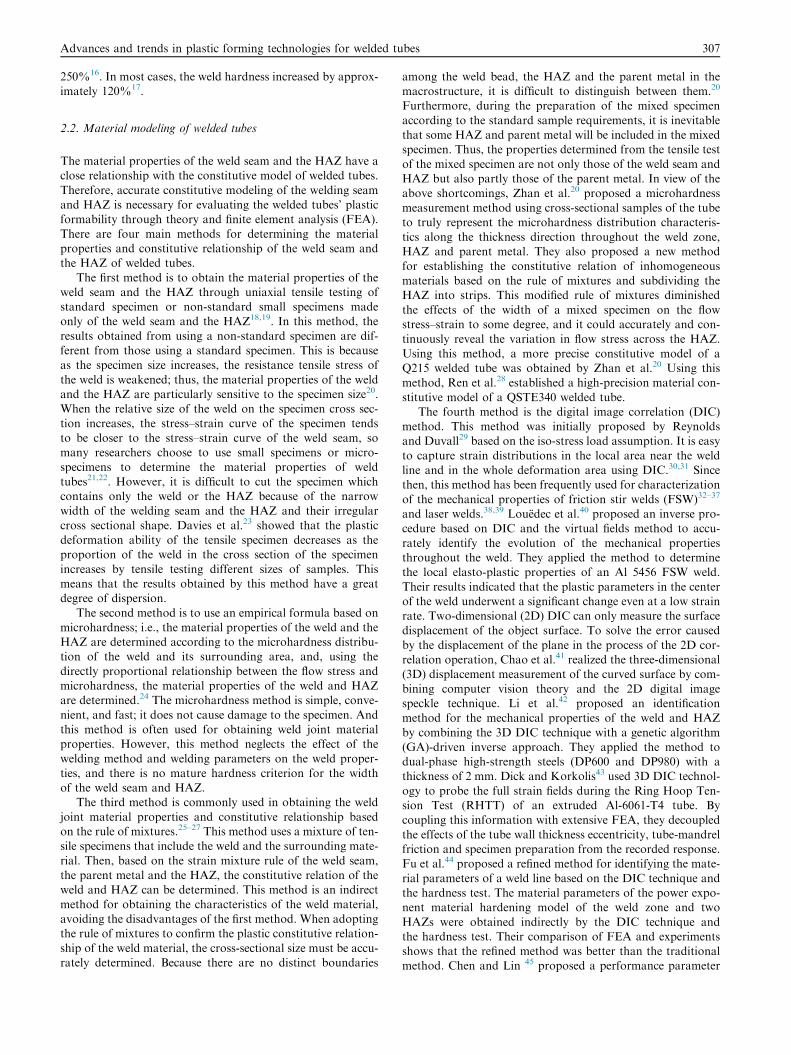
According to the treatment methods for the weld seam and theHAZ, the finite element models for welded tubes can be classi-fied into the following four categories.
The first category can be called the pure parent metal FEmodel. As shown in Fig. 1(a), the model neglects the weldand the HAZ, and the whole tube is regarded as a homoge-neous tube endowed with the material properties of the parent
metal.3 This simplified modeling method will result in incorrectresults in some cases.46 Kim et al.3 established a finite elementmodel of the welded tube free-bulging process without consid-
ering the weld and the HAZ. The simulation results show thatthe fracture integral value along the middle tube ring changedlittle. Therefore, it was difficult to predict the fracture failure
location of the welded tube free-bulging process.The second category is the FE model that includes both the
parent metal and the weld. As shown in Fig. 1(b), this modelonly considers the effect of the weld material properties and
ignores the existence of the HAZ.3 There are three methodsfor establishing the model of the weld seam.47–55 In the firstmethod, solid elements based on the size, shape and material
parameters of the weld are adopted to establish accuratelythe model of the weld. In the second method, shell elementsare used to establish a model of the weld. In the third method,
changes in the weld material properties are ignored, and con-sidering only the weld position, the weld is replaced by arow of beam elements or shell mesh elements or the weld is
treated as a rigid pivot. Zhao et al.48 described the weld usinga rigid pivot, a shell element and a solid element. Comparisonof the simulation results of these models for a free-bend test,stretch-bend test and limited dome-height test with experimen-
tal results show that the simulation accuracy was the lowestwhen the weld was simplified to a rigid pivot, and the accuracywas quite similar when the weld was simplified to shell ele-
ments and solid elements. In general, although the FE model,
dels of welded tubes.3
Advances and trends in plastic forming technologies for welded tubes 309
including both the parent metal and the weld, is closer to theactual situation than the pure parent metal model, it can stillcannot accurately predict the wall thickness variation, rupture
and failure of the HAZ in the plastic forming process,56 whilethe HAZ is always a high-failure area with low strength, poorplasticity and many inclusions and other defects.
The third category is the model that includes the weld, asingle HAZ and the parent metal. As shown in Fig. 1(c), in thismodel, the differences of the material properties of the weld
seam, the HAZ and the parent metal are considered.3 Com-pared with the previous two models, this method can accu-rately simulate the deformation characteristics of the weldjoint plastic forming. Kim et al.3 created three finite element
models for the parent metal alone (Model A), for includingthe weld and the HAZ as well (Model B), and for includingthe weld only (Model C) to numerically predict bursting failure
during the bulging process of a seamed tube. The results showthat for model B, the maximum value of the potential initialfracture site occurred near the weld line, which coincided with
one of the actual bulging tests. Therefore, the finite elementmodel containing the weld and the HAZ was the best modelamong the three models in describing the bursting behavior
numerically. Rogue et al.57 created two models of a welded-tailor tube, with and without a HAZ, to compare differentapproaches to modeling of the HAZ. They show that theresults were clearly influenced by the presence of the HAZ
and that by increasing the difference between thicknesses, thepresence of a well-defined HAZ could have greater influenceon the final results.
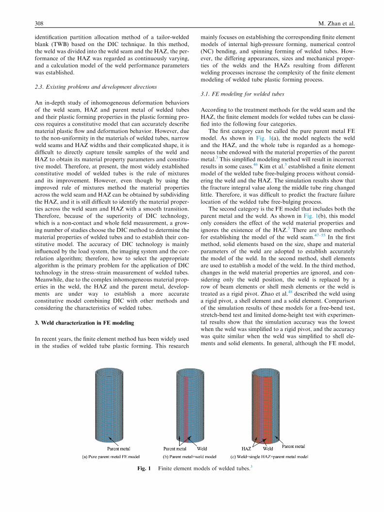
The fourth category has an FE model that includes theweld, the subdivided HAZs and the parent material (seeFig. 2). This model considers not only the differences in the
material properties between the weld and the HAZ but alsothe gradual change in the material properties of the HAZ.28
Using this method, Galdos and Garcia56 subdivided the weld
and HAZ into seven subzones. Their simulation results showthat the thickness distribution of the weld and the HAZ wereconsistent with the experimental results. Liu et al.58 studiedan FE simulation of NC bending of 60 mm � 4 mm welded
tubes. They showed that the results obtained by the simulationof the subdivided HAZ model were closer to the experimentalresults. Ren et al.28 established an FE model including the
weld, a subdivided HAZ and the parent material that consid-ered the varied material properties of each HAZ for the NC
Fig. 2 Weld + subdivided HAZ + parent metal FE model28 for
welded tubes.
bending process of 78 mm � 2.7 mm QSTE340 welded tubes.As shown in Fig. 2, each HAZ of the welded tube was subdi-vided into three subzones in this model.
3.2. Existing problems and development directions
To sum up, establishing FE models of welded tubes containing
the weld seam, a subdivided HAZ and the parent material con-sidering the varying material properties of the weld, the HAZand the parent metal for plastic forming of welded tubes has
become a trend. For the model elements, the accuracy andthe efficiency should be considered comprehensively accordingto the actual tube size and the weld characteristics.
The mechanical properties of the welded joints are smoothand continuous along the vertical direction of the weld; whilein the solid FE model, this complex continuity problem inthese domains is discretized by using mesh partitions.59
Because the widths of the weld line and the HAZ are muchnarrower than those of the parent zone, the mesh in the weldline and HAZ have to be much finer than that of the parent
zone to approach the continuity by establishing an FE modelwith the weld and subdivided HAZs. This model can improvethe simulation accuracy, on the one hand; however, in con-
trast, the calculation efficiency is low. The FE model simplify-ing the weld with a row of beam elements, shell element mesh,or a rigid hinge link has high computational efficiency but lowaccuracy because it only considers the effect of the weld posi-
tion and ignores the variation in material properties in theweld, HAZ and parent zones.
Therefore, how to establish an accurate and efficient FE
model for welded tube plastic forming considering the varia-tion in material properties across the weld seam, the HAZand the parent zone becomes a key problem at present. The
main difficulty in the process is how to model the weld seamand HAZ as accurately as possible to improve the computa-tional accuracy on the one hand and how to improve the cal-
culation efficiency on the other hand.As we all know, welding process also brings about residual
stresses as well as welding distortions and micro-structuraltransformation. Even heat treatment after welding can reduce
or remove residual stresses, it will result in variation on tubegeometry and microstructure. However, there is no researchon FE modeling considering all these effects from welding
and heat treating except for some analyses on residual stressof tubes after welding60–63. Therefore, a macro–micro coupledFE modeling for the complete process chain including welding,
heat treating, followed by the particular plastic forming isneeded to accurately simulate welded tube plastic formingprocess.
4. Constraining effect and deformation coordination in welded
tube plastic forming
Due to that the material properties are different in differentzones of welded tubes, inhomogeneous plastic deformationand mutual restriction exist in the plastic forming process ofwelded tubes. When the effect of inhomogeneous deformation
between each zone is prominent, they are incapable of deform-ing in coordination; thus, defects, such as rupture, emerge thatconstrain the normal process of welded tube plastic forming
and the improvement of forming quality and forming limit.
310 M. Zhan et al.
Therefore, inhomogeneous deformation and coordinationamong the weld, the HAZ and the parent metal will have animportant influence on the plastic forming behavior and form-
ing limit of welded tubes.
4.1. Constraining effect and deformation coordination
Except for the inhomogeneous plastic deformation and coordi-nation in the outside and inside deformation zones of seamlesstubes,64 there also exist the inhomogeneous plastic deforma-
tion and coordination in the parent metal, HAZ and weldzones of welded tubes. The inhomogeneous plastic deforma-tion and coordination of welded tubes were studied by many
scholars whose major in researching NC bending, hydroform-ing and spinning.
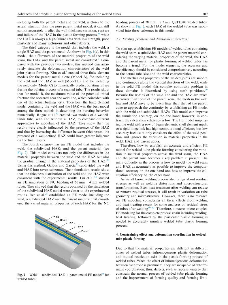
For the NC bending process of welded tubes (see Fig. 3),Ren14 proposed a constraining factor that considered the geo-
metrical characteristics and materials heterogeneity of the weldand HAZ in investigating the influence of geometrical charac-teristics and material heterogeneity of the weld region on the
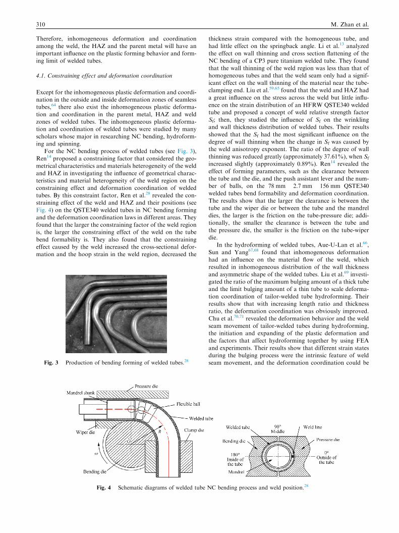
constraining effect and deformation coordination of weldedtubes. By this constraint factor, Ren et al.28 revealed the con-straining effect of the weld and HAZ and their positions (see
Fig. 4) on the QSTE340 welded tubes in NC bending formingand the deformation coordination laws in different areas. Theyfound that the larger the constraining factor of the weld regionis, the larger the constraining effect of the weld on the tube
bend formability is. They also found that the constrainingeffect caused by the weld increased the cross-sectional defor-mation and the hoop strain in the weld region, decreased the
Fig. 3 Production of bending forming of welded tubes.28
Fig. 4 Schematic diagrams of welded tube
thickness strain compared with the homogeneous tube, andhad little effect on the springback angle. Li et al.13 analyzedthe effect on wall thinning and cross section flattening of the
NC bending of a CP3 pure titanium welded tube. They foundthat the wall thinning of the weld region was less than that ofhomogeneous tubes and that the weld seam only had a signif-
icant effect on the wall thinning of the material near the tube-clamping end. Liu et al.59,65 found that the weld and HAZ hada great influence on the stress across the weld but little influ-
ence on the strain distribution of an HFRW QSTE340 weldedtube and proposed a concept of weld relative strength factorSf; then, they studied the influence of Sf on the wrinklingand wall thickness distribution of welded tubes. Their results
showed that the Sf had the most significant influence on thedegree of wall thinning when the change in Sf was caused bythe weld anisotropy exponent. The ratio of the degree of wall
thinning was reduced greatly (approximately 37.61%), when Sf
increased slightly (approximately 0.89%). Ren14 revealed theeffect of forming parameters, such as the clearance between
the tube and the die, and the push assistant lever and the num-ber of balls, on the 78 mm � 2.7 mm � 156 mm QSTE340welded tubes bend formability and deformation coordination.
The results show that the larger the clearance is between thetube and the wiper die or between the tube and the mandreldies, the larger is the friction on the tube-pressure die; addi-tionally, the smaller the clearance is between the tube and
the pressure die, the smaller is the friction on the tube-wiperdie.
In the hydroforming of welded tubes, Aue-U-Lan et al.66,
Sun and Yang67,68 found that inhomogeneous deformationhad an influence on the material flow of the weld, whichresulted in inhomogeneous distribution of the wall thickness
and asymmetric shape of the welded tubes. Liu et al.69 investi-gated the ratio of the maximum bulging amount of a thick tubeand the limit bulging amount of a thin tube to scale deforma-
tion coordination of tailor-welded tube hydroforming. Theirresults show that with increasing length ratio and thicknessratio, the deformation coordination was obviously improved.Chu et al.70,71 revealed the deformation behavior and the weld
seam movement of tailor-welded tubes during hydroforming,the initiation and expanding of the plastic deformation andthe factors that affect hydroforming together by using FEA
and experiments. Their results show that different strain statesduring the bulging process were the intrinsic feature of weldseam movement, and the deformation coordination could be
NC bending process and weld position.28
Advances and trends in plastic forming technologies for welded tubes 311
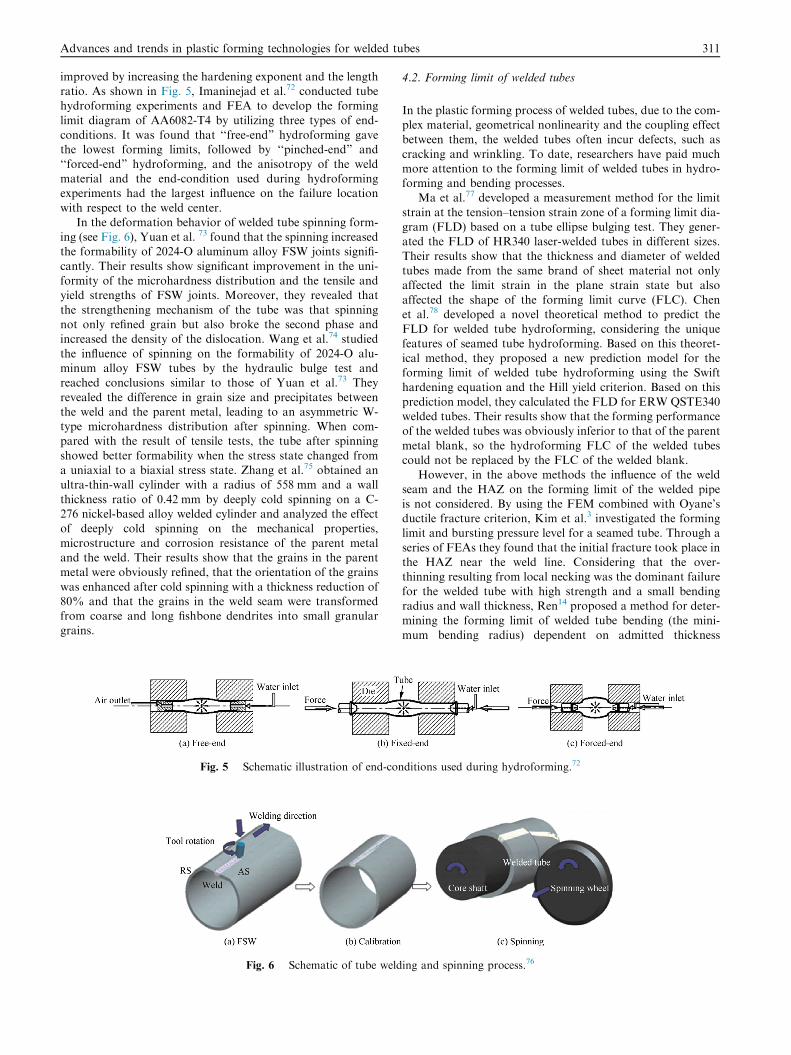
improved by increasing the hardening exponent and the lengthratio. As shown in Fig. 5, Imaninejad et al.72 conducted tubehydroforming experiments and FEA to develop the forming
limit diagram of AA6082-T4 by utilizing three types of end-conditions. It was found that ‘‘free-end” hydroforming gavethe lowest forming limits, followed by ‘‘pinched-end” and
‘‘forced-end” hydroforming, and the anisotropy of the weldmaterial and the end-condition used during hydroformingexperiments had the largest influence on the failure location
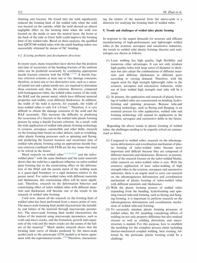
with respect to the weld center.In the deformation behavior of welded tube spinning form-
ing (see Fig. 6), Yuan et al. 73 found that the spinning increasedthe formability of 2024-O aluminum alloy FSW joints signifi-
cantly. Their results show significant improvement in the uni-formity of the microhardness distribution and the tensile andyield strengths of FSW joints. Moreover, they revealed that
the strengthening mechanism of the tube was that spinningnot only refined grain but also broke the second phase andincreased the density of the dislocation. Wang et al.74 studied
the influence of spinning on the formability of 2024-O alu-minum alloy FSW tubes by the hydraulic bulge test andreached conclusions similar to those of Yuan et al.73 They
revealed the difference in grain size and precipitates betweenthe weld and the parent metal, leading to an asymmetric W-type microhardness distribution after spinning. When com-pared with the result of tensile tests, the tube after spinning
showed better formability when the stress state changed froma uniaxial to a biaxial stress state. Zhang et al.75 obtained anultra-thin-wall cylinder with a radius of 558 mm and a wall
thickness ratio of 0.42 mm by deeply cold spinning on a C-276 nickel-based alloy welded cylinder and analyzed the effectof deeply cold spinning on the mechanical properties,
microstructure and corrosion resistance of the parent metaland the weld. Their results show that the grains in the parentmetal were obviously refined, that the orientation of the grains
was enhanced after cold spinning with a thickness reduction of80% and that the grains in the weld seam were transformedfrom coarse and long fishbone dendrites into small granulargrains.
Fig. 5 Schematic illustration of end-con
Fig. 6 Schematic of tube weld
4.2. Forming limit of welded tubes
In the plastic forming process of welded tubes, due to the com-plex material, geometrical nonlinearity and the coupling effectbetween them, the welded tubes often incur defects, such as
cracking and wrinkling. To date, researchers have paid muchmore attention to the forming limit of welded tubes in hydro-forming and bending processes.
Ma et al.77 developed a measurement method for the limit
strain at the tension–tension strain zone of a forming limit dia-gram (FLD) based on a tube ellipse bulging test. They gener-ated the FLD of HR340 laser-welded tubes in different sizes.
Their results show that the thickness and diameter of weldedtubes made from the same brand of sheet material not onlyaffected the limit strain in the plane strain state but also
affected the shape of the forming limit curve (FLC). Chenet al.78 developed a novel theoretical method to predict theFLD for welded tube hydroforming, considering the unique
features of seamed tube hydroforming. Based on this theoret-ical method, they proposed a new prediction model for theforming limit of welded tube hydroforming using the Swifthardening equation and the Hill yield criterion. Based on this
prediction model, they calculated the FLD for ERW QSTE340welded tubes. Their results show that the forming performanceof the welded tubes was obviously inferior to that of the parent
metal blank, so the hydroforming FLC of the welded tubescould not be replaced by the FLC of the welded blank.
However, in the above methods the influence of the weld
seam and the HAZ on the forming limit of the welded pipeis not considered. By using the FEM combined with Oyane’sductile fracture criterion, Kim et al.3 investigated the forminglimit and bursting pressure level for a seamed tube. Through a
series of FEAs they found that the initial fracture took place inthe HAZ near the weld line. Considering that the over-thinning resulting from local necking was the dominant failure
for the welded tube with high strength and a small bendingradius and wall thickness, Ren14 proposed a method for deter-mining the forming limit of welded tube bending (the mini-
mum bending radius) dependent on admitted thickness
ditions used during hydroforming.72
ing and spinning process.76
312 M. Zhan et al.
thinning and fracture. He found that the weld significantlyreduced the forming limit of the welded tube when the weldwas located on the outside, while the weld showed an almost
negligible effect on the forming limit when the weld waslocated on the inside or near the neutral layer; the boost atthe back of the tube or fewer balls could improve the forming
limit of the welded tube. Based on these analyses, the qualifiedbent QSTE340 welded tubes with the small bending radius wassuccessfully obtained by means of NC bending.
4.3. Existing problems and development directions
In recent years, many researchers have shown that the position
and time of occurrence of the bending fracture of the uniformtubes can be predicted accurately by combining appropriateductile fracture criterion with the FEM.3,79,80 A ductile frac-ture criterion contains at least one or two damage constants;
therefore, at least one or two destructive tests, such as a uniax-ial tensile test and a plane tensile test, are required to determinethese constants and, thus, the criterion. However, compared
with homogeneous tubes, the welded tubes consist of the weld,the HAZ and the parent metal, which have different materialproperties and widths, even different thicknesses. In addition,
the width of the weld is narrow, for example, the width oflaser-welded tubes is only 0.4–1.0 mm.81 Therefore, it is verydifficult to obtain the damage constants of the weld and theHAZ accurately. This increases the difficulty in predicting
the occurrence of a fracture in the welded tube plastic formingprocess by using a ductile fracture criterion. As a result, withthe wide application of welded tube plastic forming technology
in aviation, aerospace, automobile and other fields, researchon the forming limit based on other defects, such as wrinkling,other plastic forming processes such as spinning and flaring,
and predicting the fracture location and occurrence time ofwelded tube plastic forming using an appropriate ductile frac-ture criterion combined with FEM are the key issues that need
to be solved in the future.Much research on welded tubes13,14,28,58,61 and the tailor-
welded plate82 with the same thickness and the same materialsshows that the weld has a significant influence on tailor-welded
plate forming due to the constraining effect on the deforma-tion of the HAZ and the parent metal of the welding seamas a quasi-rigid boundary or a rigid inclusion relative to the
parent metal. For tailor-welded tubes with different materialsand thicknesses, this constraining effect will be more signifi-cant. Therefore, research on the deformation behavior and
constraining effect of tailor welded tubes with different mate-rials and thicknesses will become one of the trends in theresearch of welded tube forming.
Until now, almost all the research on the forming limit of
welded tubes has been performed from a macro point of view.The macro-scale forming limit model characterizes the instabil-ity and failure of the material through macroscopic parame-
ters. The micro-scale forming limit model characterizes thefailure of the material using microscopic parameters, such asvoids and micro cracks, and the formation, growth and expan-
sion of the void and the micro cracks are the causes of the fail-ure of the material.83 Much similar research shows that theforming limit curve of blanks predicted by the micro-scale
model (such as the anisotropic GTN model) is in better agree-ment with the experimental results. 84,85Therefore, characteriz-
ing the failure of the material from the micro-scale is adirection for studying the forming limit of welded tubes.
5. Trends and challenges of welded tubes plastic forming
In response to the urgent demands for accurate and efficientmanufacturing of high-performance and lightweight welded
tubes in the aviation, aerospace and automotive industries,the trends in welded tube plastic forming theories and tech-nologies are shown as follows.
(1) Laser welding has high quality, high flexibility andnumerous other advantages. It can not only produce
high-quality tubes with large ratios of diameter to thick-ness but also adopt the combinations of different mate-rials and different thicknesses in different parts
according to varying demand. Therefore, with theurgent need for high strength lightweight tubes in theaviation, aerospace and automotive industries, wideruse of laser welded high strength steel tube will be a
trend.(2) At present, the application and research of plastic form-
ing of welded tubes are concentrated on bending, hydro-
forming and spinning processes. Because tube-endforming technology, such as flaring and flanging, is anessential process for tube application, welded tube end
forming technology will expand its application in theaviation, aerospace and automotive fields in the future.
Regarding the above trends in plastic forming of welded
tubes, the challenges needing to be urgently solved are summa-rized as below.
(1) Compared to welded tubes, research on the inhomoge-neous deformation and coordination mechanism of plas-tic forming of tailor-welded tubes become more
important and difficult because they are composed ofdifferent materials and thicknesses. However, at present,most of the research focuses on the tailor-welded blanks,
while research on tailor-welded tubes is rare. With theextensive application of laser tailor-welding of highstrength tubes in the aviation, aerospace and automotiveindustries, there is an urgent need to carry out research
on the inhomogeneous deformation and coordinationmechanism of plastic forming of tailor-welded tubeswith different materials and thicknesses.
(2) With the plastic forming process of welded tubesexpanding from the bending, hydroforming and spin-ning toward tube-end forming, such as flaring and flang-
ing forming, it is important to perform research on theinhomogeneous deformation and coordination mecha-nism of welded tube-end forming.
(3) To accurately simulate plastic forming processes of
welded tubes, the FE modeling considering effects ofwelding on not only property difference but also residualstresses as well as welding distortions and micro-
structure is needed. For this purpose, how to establishthe modeling for the complete process chain includingthermo-mechanical coupled welding, heat treating, fol-
lowed by the particular plastic forming could be achallenge.
Advances and trends in plastic forming technologies for welded tubes 313
(4) The research characterizing the forming limit of welded
tubes is only focused on the fracture forming limit ofwelded tubes in hydroforming and bending processesfrom the macro point of view, and no general ductile
fracture criterion has been established. To accuratelypredict the fracture forming limit, a general ductile frac-ture criterion that considers the material characteristicsof welded tubes is needed. Considering that other defects
in addition to fracture, e.g., wrinkling, usually occureasily in the plastic forming process of welded tubes,research on the forming limit of other defects is needed.
Because the fracture failure of the material has a closerelationship with the voids and micro cracks, to analyzethe fracture mechanism, it is necessary to perform
researches on the forming limit of welded tubes fromthe micro point of view.
6. Conclusions
(1) Welded tube plastic forming responds to the currenturgent demands for high-performance and lightweight
components and accurate, short-cycle, low-cost manu-facturing technology in high-tech industries such as avi-ation, aerospace and automobiles. The current urgent
demand for high efficiency and precision productionare integrally related to the constraint effect of the weldzone on the plastic forming of welded tubes and to theinhomogeneous deformation and coordination mecha-
nism in welded tube plastic forming. This depends onthe insight into the nonlinearity of materials, geometri-cal effects, the complicated contact conditions and the
boundary conditions of the welded tubes, and the cou-pling effect among them. Thus, advances in the studiesof these common topics in welded tube plastic forming
are summarized, including material properties and mod-eling of welded tubes, weld characterization in FE mod-eling, constraining effect and deformation coordination
in welded tube plastic forming, and the forming limitof welded tubes.
(2) With the increasing demand for better performancetubes, more complex welded tubular components with
lighter-weight materials are required. These componentsare characterized by their thin wall thickness, largediameter, and the combination of different materials
and thicknesses. The tubular materials are generallyhard to deform, with limited ductility and high strength.Considering the facts of tough tolerances in applications
and multiple constraints with nonlinear contact condi-tions in plastic forming, several challenges need to beovercome, namely, the FE modeling for the completeprocess chain including tube welding, heat treating and
plastic forming process of welded tubes; the inhomoge-neous deformation and coordination mechanism of plas-tic forming of tailor-welded-tubes with different
materials and thicknesses; the inhomogeneous deforma-tion and coordination mechanism of welded tube-endforming; more comprehensive research on the forming
limit of welded tubes, from the point of view of the
macro or micro ductile fracture criterion considering
the material characteristics of welded tubes, and of otherdefects.
Acknowledgements
The authors acknowledge the support from the NationalScience Fund for Excellent Young Scholars of China (No.51222509); the National Natural Science Foundation of China(No. 51175429); the Research Fund of the State Key Labora-
tory of Solidification Processing (No. 97-QZ-2014 and 90-QP-2013) of China; and the Marie Curie International ResearchStaff Exchange Scheme (IRSES, MatProFuture, No. 318968)
within the 7th EC Framework Programme (FP7).
References
1. Koc M, Altan T. An overall review of the tube hydroforming
(THF) technology. J Mater Process Technol 2001;108(3):384–93.
2. Kleiner M, Homberg W, Brosius A. Process and control of sheet
metal hydroforming. Proceedings of the 6th ICTP; 1999 Sep 19–24;
Nuremberg, German. Berlin: Springer; 1999.
3. Kim J, Kim YW, Kang BS, Hwang SM. Finite element analysis
for bursting failure prediction in bulge forming of a seamed tube.
Finite Elem Anal Des 2004;40(9–10):953–66.
4. Zhao BY, Wang XS, Ding FC, Miao QB. Hydroforming of
compensator joints in rocket’s boost transport system. Aerosp
Mater Technol 2006;36(6):52–5 [Chinese].
5. Chen SJ. Microstructure evolution and mechanical behavior of
heterogeneous joint and plastic deformation optimization of
SUS304 tailor-welded tube [dissertation]. Harbin: Harbin Institute
of Technology, 2012 [Chinese].
6. Khalfallah A. Experimental and numerical assessment of mechan-
ical properties of welded tubes for hydroforming. Mater Des
2013;56(4):782–90.
7. Ghoo BY, Keum YT, Kim YS. Evaluation of the mechanical
properties of welded metal in tailored steel sheet welded by CO2
laser. J Mater Process Technol 2001;113(1–3):692–8.
8. Panda SK, Ravi KD, Kumar H, Nath AK. Characterization of
tensile properties of tailor welded IF steel sheets and their
formability in stretch forming. J Mater Process Technol 2007;183
(2–3):321–32.
9. Yang TB, Yu ZQ, Xu CB, Li SH. Numerical analysis for forming
limit of welded tube in hydroforming. J Shanghai Jiaotong Univ
2011;45(1):6–10 [Chinese].
10. Bi HY, Lu MH. Weld shape evaluation and metallographic
examination of ERW pipes. Baosteel Technology 2006;(3):23–6
[Chinese].
11. Loukus A, Subhash G, Imaninejad M. Mechanical properties and
microstructural characterization of extrusion welds in AA6082-T4.
J Mater Sci 2004;39(21):6561–9.
12. Ren N, Zhan M, Yang H, Qin YT, Zhang ZY, Jiang HM, et al.
Weld characteristic and NC bending formability study of
QSTE340 welded tube. Trans Tianjin Univ 2011;17(4):288–92.
13. Li Y, Zhan M, Wang JG, Ren N, Yang H. FE analysis of NC
bending of thin-walled CP3 welded tubes. Aeronautical Manu-
facturing Technology 2011;(16):86–93 [Chinese].
14. Ren N. Study on deformation compatibility and bending limit in
steel welded tube NC bending processes [dissertation]. Xi’an:
Northwestern Ploytechnical University, 2013 [Chinese].
15. Chan LC, Chan SM, Cheng CH, Lee TC. Formability and weld
zone analysis of tailor-welded blanks for various thickness ratios. J
Eng Mater Technol 2005;127(2):179–85.
314 M. Zhan et al.
16. Kim HJ, Heo YM, Kim N, Seo D. Forming and drawing
characteristics of tailor welded sheets in a circular draw bead. J
Mater Process Technol 2000;105(3):294–301.
17. Min KB, Kim KS, Kang SS. A study on resistance welding in steel
sheets using a tailor-welded blank (1st report): Evaluation of upset
weldability and formability. J Mater Process Technol 2000;101(1–
3):186–92.
18. Chung K, Lee W, Kim D, Kim J, Chung KH, Kim C, et al.
Macro-performance evaluation of friction stir welded automotive
tailor-welded blank sheets: part I-Material properties. Int J Solids
Struct 2010;47(7–8):1048–62.
19. Cheng CH, Jie M, Chan LC, Chow CL. True stress–strain analysis
on weldment of heterogeneous tailor-welded blanks–a novel
approach for forming simulation. Int J Mech Sci 2007;49
(2):217–29.
20. Zhan M, Du HF, Liu J, Ren N, Yang H, Jiang H, et al. A method
for establishing the plastic constitutive relationship of the weld
bead and heat-affected zone of welded tubes based on the rule of
mixtures and a microhardness test. Mater Sci Eng A 2010;527
(12):2864–74.
21. Milian JL, Adonyi Y. Formability of tailored blanks for automo-
tive applications. 34th MWSP conference proceedings; Montreal,
Canada. ISS-AIME; 1992.p. 83–91.
22. Stasik MC, Wagoner RH. Forming of tailor-welded aluminum
blanks. Int J Form Process 1998;1:9–34.
23. Davies RW, Smith MT, Khaleel MA, Pitman SG, Oliver HE.
Weld metal ductility in aluminum tailor welded blanks. Metall
Mater Trans A 2000;31(11):2755–63.
24. Reis A, Teixeira P, Duarte JF, Santos A, Rocha ABD, Fernandes
AA. Tailored welded blanks-an experimental and numerical study
in sheet metal forming on the effect of welding. Comput Struct
2004;82(17):1435–42.
25. Abdullah K, Wild PM, Jeswiet JJ, Ghasempoor A. Tensile testing
for weld deformation properties in similar gage tailor welded
blanks using the rule of mixtures. J Mater Process Technol
2001;112(1):91–7.
26. Lee W, Chung K, Kim D, Kim J, Kim C, Okamoto K, et al.
Experimental and numerical study on formability of friction stir
welded TWB sheets based on hemispherical dome stretch tests. Int
J Plast 2009;25(9):1626–54.
27. Kim D, Lee W, Kim J, Kim C, Chung KD. Formability
evaluation of friction stir welded 6111–T4 sheet with respect to
joining material direction. Int J Mech Sci 2010;52(4):612–25.
28. Ren N, Zhan M, Yang H, Zhang ZY, Qin YT, Jiang HM, et al.
Constraining effects of weld and heat-affected zone on deforma-
tion behaviors of welded tubes in numerical control bending
process. J Mater Process Technol 2012;212(5):1106–15.
29. Reynolds AP, Duvall F. Digital image correlation for determina-
tion of weld and base metal constitutive behavior. Weld J 1999;78
(10):S355–60.
30. Brauser S, Pepke LA, Weber G, Rethmeier M. Deformation
behavior of spot-welded high strength steels for automotive
applications. Mater Sci Eng A 2010;527(26):7099–108.
31. Tung SH, Shih MH, Kuo JC. Application of digital image
correlation for anisotropic plastic deformation during tension
testing. Opt Lasers Eng 2010;48(5):636–41.
32. Genevois C, Deschamps A, Vacher P. Comparative study on local
and global mechanical properties of 2024 T351, 2024 T6 and 5251
O friction stir welds. Mater Sci Eng A 2006;415(1–2):162–70.
33. Hatamleh O. Effects of peening on mechanical properties in
friction stir welded 2195 aluminum alloy joints. Mater Sci Eng A
2008;492(1–2):168–76.
34. Brown R, Tang W, Reynolds AP. Multi-pass friction stir welding
in alloy 7050–T7451: effects on weld response variables and on
weld properties. Mater Sci Eng A 2009;513–514:115–21.
35. Leitao C, Galvao I, Leal RM, Rodrigues DM. Determination of
local constitutive properties of aluminium friction stir welds using
digital image correlation. Mater Des 2012;33:69–74.
36. Zadpoor AA, Sinke J, Benedictus R. Finite element modeling and
failure prediction of friction stir welded blanks.Mater Des 2009;30
(5):1423–34.
37. Zadpoor AA, Sinke J, Benedictus R. Global and local mechanical
properties and microstructure of friction stir welds with dissimilar
materials and/or thicknesses. Metall Mater Trans A 2010;41
(13):3365–78.
38. Boyce B, Reu P, Robino C. The constitutive behavior of laser
welds in 304L stainless steel determined by digital image correla-
tion. Metall Mater Trans A 2006;37(8):2481–92.
39. Scintilla LD, Tricarico L, Brandizzi M, Satriano AA. Nd:YAG
laser weld ability and mechanical properties of AZ31 magnesium
alloy butt joints. J Mater Process Technol 2010;210(15):2206–14.
40. Louedec GL, Pierron F, Sutton MA, Reynolds AP. Identification
of the local elasto-plastic behavior of FSW welds using the virtual
fields method. Exp Mech 2013;53(5):849–59.
41. Chao YJ, Sutton MA, Peter WH, Luo PF. Measurement of three-
dimensional displacements in deformable bodies by digital image
processing. Spring Conference on Experimental Mechanics; 1989
May 29-Jun 1; Cambridge MA. Springer; 1989. p. 139–46.
42. Li GY, Xu FX, Sun GY, Li Q. Identification of mechanical
properties of the weld line by combining 3D digital image
correlation with inverse modeling procedure. Int J Adv Manuf
Technol 2014;74(5–8):893–905.
43. Dick CP, Korkolis YP. Strength and ductility evaluation of cold-
welded seams in aluminum tubes extruded through porthole dies.
Mater Des 2015;67:631–6.
44. Fu L, Liu DH, Sun YG, Li GY, Xu FX, Chen SS. A refined
method to identify material parameters of weld line based on DIC
technique and hardness test. Chin Mech Eng 2013;24(2):274–9
[Chinese].
45. Chen SS, Lin JP. A novel method for measuring the weld property
of tailor welded blanks based on DIC. Trans Chin Weld Inst
2013;34(8):76–80 [Chinese].
46. Tian HB, Lin JP, Liu RT, Xun YC. A review on ultralight auto
body and related forming technologies. Automot Eng 2005;27
(3):381–4 [Chinese].
47. Bhagwan AV, Kridli GT, Friedman PA. Influence of weld
characteristics on numerically predicted deformation behavior of
aluminum tailor welded blanks. SAE Technical Paper; 2002. No.:
2002-01-0386.
48. Zhao KM, Chun BK, Lee JK. Finite element analysis of tailor-
welded blanks. Finite Elem Anal Des 2001;37(2):117–30.
49. Meinders T, Berg AVD, Huetink J. Deep drawing simulations of
tailored blanks and experimental verification. J Mater Process
Technol 2000;103(1):65–73.
50. Zimniak Z, Piela A. Finite element analysis of a tailored blanks
stamping process. J Mater Process Technol 2000;106(1–3):254–60.
51. Iwata N, Matsui M, Nakagawa N, Ikura S. Improvements in
finite-element simulation for stamping and application to the
forming of laser-welded blanks. J Mater Process Technol 1995;50
(1–4):335–47.
52. Jiang H, Li SH, Wu H, Chen XP. Numerical simulation and
experimental verification in the use of tailor-welded blanks in the
multi-stage stamping process. J Mater Process Technol 2004;151
(1–3):316–20.
53. Nakagawa N, Ikura S, Natsumi F, Iwata N. Finite element
simulation of stamping a laser-welded blank. SAE Technical
Paper; 1993. No.: 930522.
54. Kampusa Z, Balic J. Deep drawing of tailored blanks without a
blank holder. J Mater Process Technol 2003;133(1–2):128–33.
55. Raymond SD, Wild PM, Bayley CJ. On modeling of the weld line
in finite element analyses of tailor-welded blank forming opera-
tions. J Mater Process Technol 2004;147(1):28–37.
56. Galdos L, Garcia C. Innovative method for welded tube charac-
terization and tube hydroforming process modeling. Proceedings
of the 8th ICTP: Advanced Technology of Plasticity; 2005 Oct 9–13;
Verona, Italy. Springer; 2005.p. 299–307.
Advances and trends in plastic forming technologies for welded tubes 315
57. Rogue AP, Natal Jorge RM, Parente MPL, Valente RAF,
Fernandes AA. Influence of the heat affected zone on hydroform-
ing with tailor-welded tubular blanks. In: Onate E, Owen DRJ,
editors. International Conference on Computational Plasticity;
2005.p.1-4.
58. Liu J, Yang H, Zhan M, Ren N. Finite element modeling of
seamed tube NC bending process and its application. Mater Res
Innov 2011;15(s1):s315–8.
59. Chu GN, Wang XS. Laser weld-seam modeling for finite element
analysis during tailor-welded tube hydroforming. J Mech Eng
2012;48(22):34–9 [Chinese].
60. Lee CH, Baek JH, Chang KH. Bending capacity of girth-welded
circular steel tubes. J Constr Steel Res 2012;75:142–51.
61. Lacki P, Adamus K, Wieczorek P. Theoretical and experimental
analysis of thermo-mechanical phenomena during electron beam
welding process. Comput Mater Sci 2014;94:17–26.
62. Xu S, Wang W, Chang Y. Using FEM to predict residual stresses
in girth welding joint of layered cylindrical vessels. Int J Press
Vessels Pip 2014;119:1–7.
63. Xu S, Zhao Y. Using FEM to determine the thermo-mechanical
stress in tube to tube-sheet joint for the SCC failure analysis. Eng
Fail Anal 2013;34:24–34.
64. Yang H, Li H, Zhang Z, Zhan M, Liu J, Li GJ. Advances and
trends on tube bending forming technologies. Chin J Aeronaut
2012;25(1):1–12.
65. Liu J, Yang H, Zhan M, Ren N, Jiang HM, Diao KS, et al.
Influence of weld relative strength on wrinkling and wall thickness
distribution of thin- walled seamed tube in rotary draw bending
process. Mater Sci Technol 2011;19(6):1–6 [Chinese].
66. Aue-U-Lan Y, Ngaile G, Altan T. Optimizing tube hydroforming
using process simulation and experimental verification. J Mater
Process Technol 2004;146(1):137–43.
67. Sun KR, Yang LF. Tailor-welded tube in hydroforming and
influence of the heat affected zone on bulge forming. J Guilin Univ
Electron Technol 2006;26(5):380–4 [Chinese].
68. Sun KR, Yang LF. Comparison of deformation behaviors of
seamed tube and seamless tubes in hydroforming. Chin Mech Eng
2006;17(Suppl.):27–31 [Chinese].
69. Liu G, Chu GN, Yu C, Yuan SJ. Deformation compatibility of
hydroforming for tailor-welded tube with dissimilar thickness. J
Basis Sci Eng 2009;17(3):477–84 [Chinese].
70. Chu GN, Liu G, Yuan SJ. Plastic deformation regularity of tailor-
welded tube (twt) with dissimilar thickness during hydro-bulging.
Acta Metall Sinica 2008;44(12):1479–84 [Chinese].
71. Chu GN, Liu G, Yuan SJ, Liu WJ. Weld seam movement of
tailor-welded tube during hydrobulging with dissimilar thickness.
Int J Adv Manuf Technol 2012;60(9):1255–60.
72. Imaninejad M, Subhash G, Loukus A. Influence of end-conditions
during tube hydroforming of aluminum extrusions. Int J Mech Sci
2004;46(8):1195–212.
73. Yuan SJ, Hu ZL, Wang XS. Formability and microstructural
stability of friction stir welded Al alloy tube during subsequent
spinning and post weld heat treatment. Mater Sci Eng A
2012;558:586–91.
74. Wang XS, Hu ZL, Yuan SJ, Hua L. Influence of tube spinning on
formability of friction stir welded aluminum alloy tubes for
hydroforming application. Mater Sci Eng A 2014;607:245–52.
75. Zhang HL, He J, Li XH, Deng R. Effect of deeply cold spinning
on properties of ultra-thin-wall large radius-thickness ratio nickel-
based alloy welded cylinder. Mater Mech Eng 2011;35(6):68–71
[Chinese].
76. Yuan SJ, Hu ZL, Wang XS. Evaluation of formability and
material characteristics of aluminum alloy friction stir welded tube
produced by a novel process. Mater Sci Eng A 2012;543(5):210–6.
77. Ma CH, Yu ZQ, Chen XP, Chen XF, Lin ZQ. Experimental study
on forming limit diagram of laser welded tube hydroforming. J
Mech Eng 2013;49(2):49–53 [Chinese].
78. Chen XF, Yu ZQ, Hou B, Li SH, Lin ZQ. Prediction model for
forming limit of welded tube hydroforming. J Mech Eng 2011;47
(20):116–20 [Chinese].
79. Li H, Yang H, Zhan M. A study on critical thinning in thin-walled
tube bending of al-alloy 5052O via coupled ductile fracture
criteria. In: Barlat F, Moon YH, Lee MG, editors. Proceedings of
the 10th International Conference; 2010 Jun 13–17; Pohang, Korea.
AIP Publishing; 2010. p. 1286–94.
80. Zhan M, Gu CG, Jiang Z, Hu L, Yang H. Application of ductile
fracture criteria in spin-forming and tube-bending processes.
Comput Mater Sci 2009;47(2):353–65.
81. Anand D, Boudreau G, Andreychuk P, Chen DL, Bhole SD.
Forming behaviour of tailor (laser)-welded blanks of automotive
steel sheet. Can Metall Q 2006;45(2):189–98.
82. Saunders FI, Wagoner RH. Forming of tailor-welded blanks.
Metall Mater Trans A 1996;27(9):2605–16.
83. Li YH, Lin JP. Status-quo and trends of researches on tailor
welded blanks for vehicle body. Automot Eng 2014;36(6):763–7
[Chinese].
84. Abbasi M, Bagheri B, Ketabchi M, Haghshenas DF. Application
of response surface methodology to drive GTN model parameters
and determine the FLD of tailor welded blank. Comput Mater Sci
2012;53(1):368–76.
85. Kami A, Dariani BM, Vanini AS, Dan SC, Banabic D. Numerical
determination of the forming limit curves of anisotropic sheet
metals using GTN damage model. J Mater Process Technol
2015;216:472–83.
Zhan Mei is a professor and Ph.D. supervisor at School of Materials
Science and Engineering, Northwestern Polytechnical University,
Xi’an, China. She received the Ph.D. degree from the same university
in 2000. Her current research interests are the unequal deformation
theory and precision plastic forming technology of thin-walled com-
plex components of hard-to-deform materials, including bending
forming of tubes, spinning of complicates, and electromagnetic
forming of intefral airframe structures.
Guo Kun is a M.D. student at School of Materials Science and Engi-
neering, Northwestern Polytechnical University. She received her B.S.
degree from Northeastern University in 2014. Her area of research
includes bending forming of tubes and electromagnetic forming of
integral panel.
Yang He is a professor and Ph.D. supervisor at School of Materials
Science and Engineering, Northwestern Polytechnical University,
Xi’an, China. He received the Ph.D. degree from the Harbin Institute
of Technology in 1990. His current research interests are precise plastic
forming about aluminum alloy, magnesium alloy and titanium alloy,
high performance lightweight forming of complex structures, and
inhomogeneous deformation of difficult to deform materials.