Embed Size (px)
Citation preview

Advanced Tutorial – Designing Type V LED Roadway Lenses
This tutorial demonstrates the design process for a smooth roadway lens designed around an LED source, to be arrayed in a roadway luminaire. The LED’s are to be arrayed 20mm x 20mm, with 60 LED’s total. The tutorial covers both round and square Type V IES classification designs, and briefly explains how other types can also be created in Photopia. It is a good idea to complete the beginner tutorials before attempting this advanced tutorial, since many of the more basic functions and concepts are not explained in this tutorial.
Start the Project
1. Start a new project and choose File > Save As to give it a name such as LED Type V Round.
2. If the units are not already in millimeters, then change them to millimeters by selecting Settings > Project Settings and selecting Millimeters from the Length Units setting.
Even though the final product of this design type is an array of 60 LED’s with an array of 60 identical lenses, we can design a lens around just one LED. If all lenses in an array are identical, it is generally very accurate to model just one LED/lens unit, scaling the output of the single LED to represent the output of 60 LED’s. However, we will need to account for any potential shadowing of nearby lenses, and so we will later make a small array of the nearby lenses.
3. To import the LED, choose File > Import Lamp and then browse for LED file named 3535XPG.LAMP, which is the CREE XP-G. Insert the LED at 0,0.
Build the Lens
Lenses are built in Photopia by defining a base profile to start with, and then an offset profile is automatically created. By default, the base profile is the inside lens surface with its shape defined by you, and the offset profile is the outside lens surface and its shape controls the direction of the light. First, we will create our base profile as a hemispherical entry for the LED light.
4. From the front view, choose Draw > Arc.
a. Enter C to choose to specify the center point.
b. Enter 0,0 for the arc center.
c. Enter 0,-2 for the start point of the arc.
d. Enter 90 for the arc angle extent.

2 Advanced Tutorial – Type V LED Roadway Lenses
5. Select the new arc by clicking on it, and choose Design > Lens > 2D Base Profile. Press Enter to accept the default lamp center of 0,0.
6. Under General in the property control, change the Name to Hemisphere.
Now that we have made the base profile, we can create the lens around it.
7. With the base profile selected, choose Design > Lens > Revolved.
a. The default profile type is stepped. We will later change the profile type to smooth, but for now, accept the default number of prism steps by pressing Enter.
b. We will be assigning acrylic as the material for the lens, so the default index of refraction of 1.491 is appropriate. Press Enter to accept the default value.
c. Enter 0 for the aiming of the start of the profile, in degrees.
d. Enter 70 for the aiming of the end of the profile, in degrees.
e. Enter 2.5 for the angle increment, in degrees.
f. Enter 2 for the minimum thickness, in mm.
g. Enter 180 for the number of revolve segments to create a fine resolution to represent a smoothly revolved part.

3 Advanced Tutorial – Type V LED Roadway Lenses
The lens has now been created, but there are a few adjustments we need to make before we have an initial design. To make the lens surface smooth rather than stepped:
8. Change the Profile Type under Optical Parameters in the property control from Stepped to Smooth.
9. To make a finer resolution along the curve profile, change the Number of Curve Segments under Tooling Constraints in the property control to 40.

4 Advanced Tutorial – Type V LED Roadway Lenses
We also need to make sure we are using the correct pieces of optional geometry in order to join all the surfaces into one closed mesh.
10. Find the Optional Geometry section in the property control. Make sure that Close Start is set to No, Close End is set to Yes, Sides that are Active is set to Both, and Cap Ends is set to No.
Array the Lens
Now that we have an initial design, we can make a small array of the lens to account for any shadowing of the lenses that are nearby. Remember that we are modeling the entire array of 60 LED’s and lenses with only one LED, so we need to make sure to account for any light interaction that may occur with surrounding lenses.
11. Click the lens in CAD view to select it.
12. Find the Arraying section towards the bottom of the property control. Change the Array Type from None to Rectangular.
13. Enter 3 for the Number of Columns and the Number in the Z, and 20 for the Column Spacing and Z Spacing, in mm.

5 Advanced Tutorial – Type V LED Roadway Lenses
14. From the top view, center the array under the LED by choosing Modify > Move to move the array to the left 20mm and up 20mm.
The lenses immediately surrounding the center lens with the LED will model any shadowing or other light interaction that may occur, so we can now use just one LED to model the design, accurately representing an array of 60 LED/lens units.
Setup the Materials and Output
15. Choose Edit > Design Properties to assign the materials. Under the Refractive tab, assign Generic Standard Acrylic to the REFR-Main layer. Note that you will also see some layers that already have materials assigned to them. These are the LED layers that were imported with the LED model and they are already setup correctly for the LED.
6 Advanced Tutorial – Type V LED Roadway Lenses
16. Back under the Lamp tab, change the Lumens to 20100 per lamp and the Lamp Wattage to 199.2 per lamp. These values come from multiplying the values of one LED by 60, so that modeling one LED will represent the entire array of 60 LED’s.
17. Choose Analysis > Photometric Output Specification and go to the Photometric Report tab. Change the Report Type to Roadway. Then change the Horizontal angle set to 0 and the Vertical angle set to 0(5)180.

7 Advanced Tutorial – Type V LED Roadway Lenses
18. Under the Illuminance tab, create an illuminance plane 100m x 100m, 10m below the luminaire. Click OK twice to close the Photometric Output dialog.
19. Under Analysis > Specify Raytrace Settings, change the Number of Ray Reactions to 50 since projects with lenses need more ray reactions than projects with just reflectors. Click OK.

8 Advanced Tutorial – Type V LED Roadway Lenses
Design Results
20. Choose File > Save to save the project.
21. Start the analysis by choosing Analysis > Begin Analysis.
22. To view some of the output results, choose View > Illuminance > Shaded Plot and View > Candela Distribution > Polar Plot.
The results show a round Type V pattern that has a rather smooth illuminance pattern. The candela plot shows that although it is a wide beam, it does not peak at 70°, our highest aiming angle. The reason for this lower peak is that the LED’s light distribution puts more lumens into the center portion of the lens than the part aimed at the wide angles in the beam. We can raise the peak by giving a heavier weighting to the higher aiming angles of the lens.
Adjust the Lens
23. After selecting the lens array by clicking on it in CAD view, choose View > Parametric Optical Design and click the Section Aiming Properties radio button.

9 Advanced Tutorial – Type V LED Roadway Lenses
Notice the weighting display in the left part of this screen. Watch the weighting display change as you increase the weighting of the higher angles:
24. Change the Weight Exponent under Weighting in the property control to 2.
The weighting display and the lens profile have been updated to show the new heavier weighting of the higher aiming angles. Run the analysis again to check how the results have changed.
25. Start the analysis again by choosing Analysis > Begin Analysis, and check the results.

10 Advanced Tutorial – Type V LED Roadway Lenses
Looking at the candela plot, the peak beam angle is now closer to the highest aiming angle of 70°. The peak could be pushed higher with an even higher exponent or by adding a higher peak aiming angle, but the current beam looks acceptable for this tutorial.
Looking at the lens profile, it may be necessary to prevent the lens curvature from curving inward at the top, depending on how a flange will be added to the design or how this lens might be joined to the others in the array.
We can avoid the inward curvature by changing the inner surface profile from a simple arc to a shape that flares out near its base.
26. From the front view, create an alternative base profile by choosing Design > Lens > 2D Base Profile.
a. Press Enter to accept the default lamp center of 0,0.
b. Enter 0,-2 for the start of the base profile.
c. Enter 1.9,-0.6 for the next profile point.
d. Enter 2.2,0 for the last profile point, and then press Enter again to end the profile.
27. Zoom in to find the profile you just created and click on it to select it.

11 Advanced Tutorial – Type V LED Roadway Lenses
28. Under General in the property control, enter Flared Profile for the Name.
29. In Parametric Optical Design View (under the View menu), click on the Base Profile Properties radio button. Change the Angular Extent of the first section to 70 (degrees) and of the second section to -25 (degrees).

12 Advanced Tutorial – Type V LED Roadway Lenses
30. Back in the CAD view, move the new Flared Profile to the position of the original lens. (Recall that the original lens was arrayed and then moved so that the array would be centered over the LED.) From the top view, choose Modify > Move to move the array to the left 20mm and up 20mm.
31. Deselect the Flared Profile by pressing Esc. Select the lens array and change the Base Profile Name (under Base Profile in the property control) to the profile that you just created, Flared Profile.

13 Advanced Tutorial – Type V LED Roadway Lenses
Notice that the outer profile no longer curves inward. The top part of the new inner profile refracts light downward as it enters the lens, thus reducing the amount of refraction required by the outer surface.
32. Re-run the analysis and check the results to ensure that the new base profile did not negatively affect the results.
33. Save the file by choosing File > Save.
Create a Square Pattern
We have now easily created a Type V round distribution, but a square distribution may be more useful in applications such as a parking lot of several luminaires in a grid layout. A lens that creates a square pattern should have one profile as a side profile to aim towards each of the four sides of the square pattern, should have a different profile (that throws the light slightly farther) as a corner profile to aim towards each of the four corners of the square pattern, and should smoothly transition between profiles. We can use the profile we have already designed as the side profile, and we can create a new profile that aims light slightly higher for the corner profile. We will then loft the profiles and use the loft symmetry property to create the closed lens.
34. Making sure you have already saved your Type V round Photopia file, choose File > Save As to save the square design as a separate file, such as LED Type V Square.
To prepare the round design for use as the side profile for the square design:

14 Advanced Tutorial – Type V LED Roadway Lenses
35. Change the Array Type under Arraying in the property control to None so that we have a simpler model to work with.
36. Move the lens, as well as the spare profile, down 20mm and right 20mm to be centered under the LED.
37. Under Settings > Layers, change the REFR-Main layer name to REFR-Side. Create two new layers named REFR-Corner and REFR-Square Lens, and assign colors Green and Blue respectively. Set the Current Layer to the new REFR-Square Lens layer. We will use these new layers later.
38. Extract the side profile by choosing Design > Lens > Extract 2D Lens Profile while the round lens is selected. The extracted profile will automatically be placed on a new layer named REFR-Side-Profile.
To make the corner profile, we can start with a copy of the side lens design, which is the lens design we already made.

15 Advanced Tutorial – Type V LED Roadway Lenses
39. Select the revolved lens and choose Modify > Copy and make the copy in place (using 0,0 both for the base point and for the second point).
40. Select one of the lens copies and change its Layer (under General in the property control) to REFR-Corner.
41. Under Settings > Layers, turn the REFR-Side layer Off.
Now we can adjust the lens design to aim towards slightly higher angles, giving us an appropriate corner profile.
42. With the lens selected, go back to the Parametric Optical Design View (under View) and click on the Section Aiming Properties radio button. Under Aiming of Sections, make sure the By Direction radio button is selected, then enter 0(2.5)72.5 into the text field. Click Update Aiming.
Before we combine the profiles, confirm that the corner profile’s resulting pattern is acceptable.
43. Choose Edit > Design Properties to assign Generic Standard Acrylic to the REFR-Corner and REFR-Square Lens layers.
44. Run the analysis by choosing Analysis > Begin Analysis.
45. Open the Shaded Illuminance Plane and Polar Candela Plot.

16 Advanced Tutorial – Type V LED Roadway Lenses
The pattern remains smooth in the shaded illuminance plot and the peak candela is slightly higher than it was with the side profile, so this design looks appropriate so far for the corner profile of the lens.
46. Extract the corner profile by choosing Design > Lens > Extract 2D Lens Profile while the lens is selected. The extracted profile will automatically be placed on a new layer named REFR-Corner-Profile. The new corner profile should automatically be selected after extracting; leave the profile selected for the next step.
47. From the top view, rotate the new corner profile about 0,0 by 45 degrees so that it is properly positioned.
48. Under Settings > Layers, turn the REFR-Corner layer Off.
Now that we have a side profile and a corner profile, we are ready to loft the profiles and use symmetry to complete the lens.
49. To loft the profiles, choose Design > Lens > Loft 2D Lens Profiles. Click the side profile first, then the corner profile. Then press Enter to end the command.

17 Advanced Tutorial – Type V LED Roadway Lenses
50. Select the new lofted lens and change its Layer under General in the property control to REFR-Square Lens.
51. Change the Profile Symmetry under Loft in the property control from None to Octalateral.
52. Change the Surface Smoothness, also under Loft, from Straight to Normal.
Before testing the new lofted lens, array the lens again so that we can model potential interaction with surrounding lenses.
53. To array the lens again, select the new lofted lens and change the Array Type under Arraying in the property control from None to Rectangular. Enter 3 for the Number of Columns and for the Number in the Z. Enter 20, in mm, for the Column Spacing and for the Z Spacing.
54. Use the move command again (under Modify > Move) to move the array and center it under the LED.

18 Advanced Tutorial – Type V LED Roadway Lenses
Since the output is no longer axially symmetric, we need to change the horizontal angle output specification before running the analysis.
55. Under Analysis > Specify Photometric Output, under the Photometric Report tab, change the Horizontal angle set to 0(10)90.
56. Run the analysis by choosing Analysis > Begin Analysis and check the results.

19 Advanced Tutorial – Type V LED Roadway Lenses
The light pattern is not very smooth since there is a prominent X shape. The issue is also seen in the candela plot when comparing the 40 & 50 degree horizontal angle curves to the 0 & 90 degree horizontal angle curves. The intensities for most of the plot are larger for the corner horizontal angles than for the side horizontal angles, indicating an X pattern.
This issue is likely caused by the corner profile differing too much from the side profile. The two profiles should be very similar in shape to avoid light patterns that stand out. The profiles should be close to identical for most of the geometry, with the corner profile just adding enough higher angle light to create more of a square pattern. However in this case, adding that extra aiming section (72.5°) to the corner profile affected the weighting of the whole profile, since that section is weighted the heaviest of all the aiming sections. We do want the corner design to include this higher angle, but by including an additional angle with such a high weight, all of the other aiming sections are now significantly affected as well, causing the entire profile to be significantly different from the original side profile. Our corner profile should only be slightly different from our side profile in order to make a smooth transition between them. If we decrease the weight exponent on the corner design profile, we can get a profile with its lower aiming sections more closely matching the side design profile, while still including the additional aiming section at 72.5°.
57. To easily locate the corner profile in CAD view so that we can alter it, choose Settings > Layers and turn the REFR-Square Lens layer Off.
58. Click the corner profile to select it, which is the profile that has been rotated by 45 degrees.
59. Change the Weight Exponent under Weighting in the property control to a lower value of 1.8. This will allow the corner profile to be closer in shape to the side profile, while still including the additional higher aiming angle.

20 Advanced Tutorial – Type V LED Roadway Lenses
60. Choose Settings > Layers again to turn the REFR-Square Lens layer back On.
Comparing the shape of the new lofted lens to our previous lofted lens, it is subtly apparent that our new shape is slightly more round and less square. This shape change means that the profiles do not change relatively much as they are lofted around the LED (since a perfectly round shape would mean that the profiles do not change at all). Run the analysis to see if the adjusted corner profile has improved the results.
61. Run the analysis by choosing Analysis > Begin Analysis and check the results.
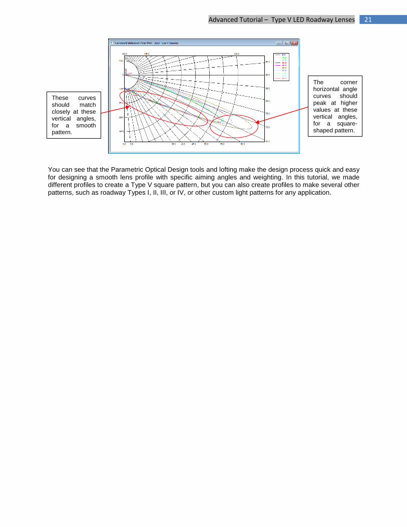
We now have a rather smooth Type V square design. The shaded illuminance plane appears to be much smoother, and the various horizontal angle curves match up much more closely in the candela plot. Note that the 40 & 50 degree horizontal angle curves do still show higher intensities at the higher vertical angles, and this makes sense and is actually preferred because this is the light that reaches further to fill in the outer corners of the square pattern shape. The lower vertical angles should match up closely, as they do.
21 Advanced Tutorial – Type V LED Roadway Lenses
You can see that the Parametric Optical Design tools and lofting make the design process quick and easy for designing a smooth lens profile with specific aiming angles and weighting. In this tutorial, we made different profiles to create a Type V square pattern, but you can also create profiles to make several other patterns, such as roadway Types I, II, III, or IV, or other custom light patterns for any application.
These curves should match closely at these vertical angles, for a smooth pattern.
The corner horizontal angle curves should peak at higher values at these vertical angles, for a square-shaped pattern.


![tPad: Designing Transparent-Display Mobile Interactionshci.cs.umanitoba.ca/assets/publication_files/2014_tPad_DIS.pdf · shown with tool-glasses and magic lenses [4], tangible views](https://img.pdfslide.us/doc/110x75/60097f52eb55e146a3152c75/tpad-designing-transparent-display-mobile-shown-with-tool-glasses-and-magic-lenses.jpg)