Embed Size (px)
Citation preview
Advanced Thermoelectric Materials and Generator
Technology for AutomotiveWaste Heat at GMGregory P. Meisner
General Motors Global Research & DevelopmentWarren, MI
2011 Thermoelectrics Applications WorkshopJanuary 3-6, 2011
Hotel Del CoronadoSan Diego, CA
2
Thermoelectric Research and Development Projects at GM Global R&D
Introduction: TE Technology for Waste Heat Recovery
AcknowledgementsThermoelectric Materials ResearchThermoelectric Generator DevelopmentResultsSummary: Current/Future Work
Outline
Com
bust
ion
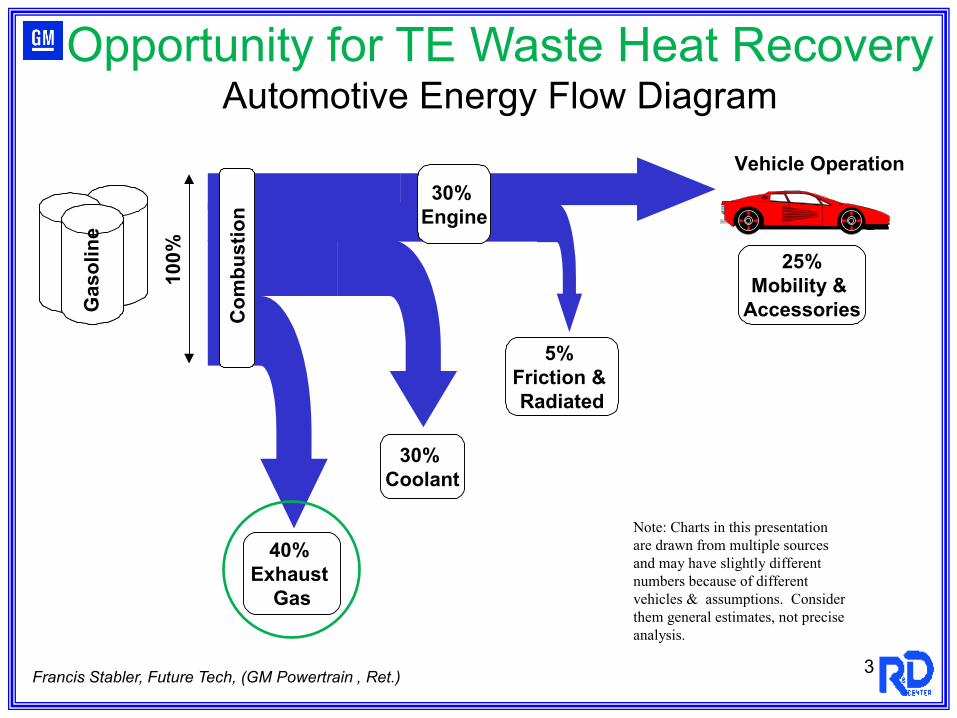
30% Engine
Vehicle Operation10
0%
40% Exhaust
Gas
30% Coolant
5% Friction & Radiated
25%Mobility &
Accessories
Gas
olin
eG
asol
ine
Gas
olin
eG
asol
ine
Gas
olin
eG
asol
ine
Note: Charts in this presentation are drawn from multiple sourcesand may have slightly different numbers because of different vehicles & assumptions. Considerthem general estimates, not preciseanalysis.
Francis Stabler, Future Tech, (GM Powertrain , Ret.)
Opportunity for TE Waste Heat RecoveryAutomotive Energy Flow Diagram
3
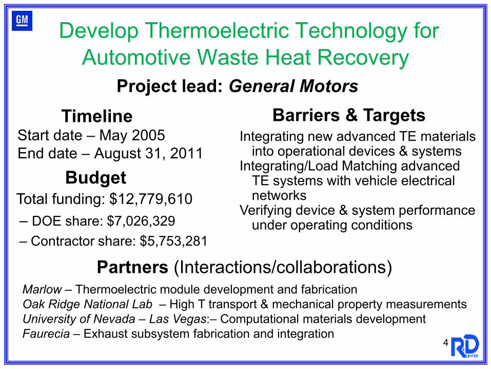
Develop Thermoelectric Technology for Automotive Waste Heat Recovery
Start date – May 2005End date – August 31, 2011
Integrating new advanced TE materials into operational devices & systems
Integrating/Load Matching advanced TE systems with vehicle electrical networks
Verifying device & system performance under operating conditions
Timeline
Budget
Barriers & Targets
Partners (Interactions/collaborations)
Total funding: $12,779,610– DOE share: $7,026,329– Contractor share: $5,753,281
Marlow – Thermoelectric module development and fabrication Oak Ridge National Lab – High T transport & mechanical property measurementsUniversity of Nevada – Las Vegas:– Computational materials developmentFaurecia – Exhaust subsystem fabrication and integration
Project lead: General Motors
4
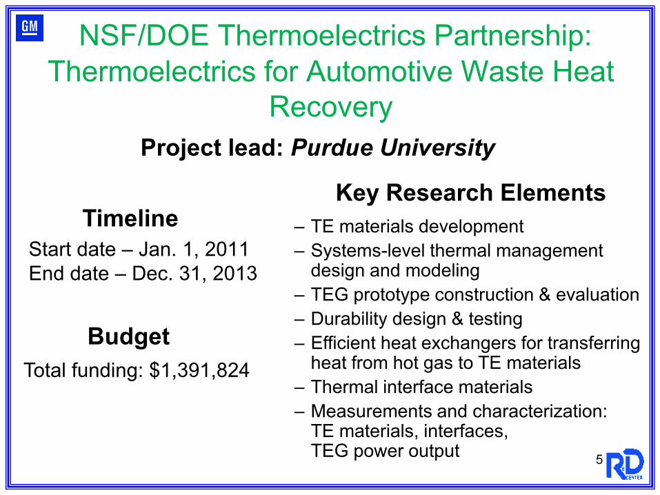
NSF/DOE Thermoelectrics Partnership: Thermoelectrics for Automotive Waste Heat
Recovery
Start date – Jan. 1, 2011End date – Dec. 31, 2013
– TE materials development– Systems-level thermal management
design and modeling– TEG prototype construction & evaluation– Durability design & testing– Efficient heat exchangers for transferring
heat from hot gas to TE materials– Thermal interface materials– Measurements and characterization:
TE materials, interfaces, TEG power output
Timeline
Budget
Key Research Elements
Total funding: $1,391,824
Project lead: Purdue University
5
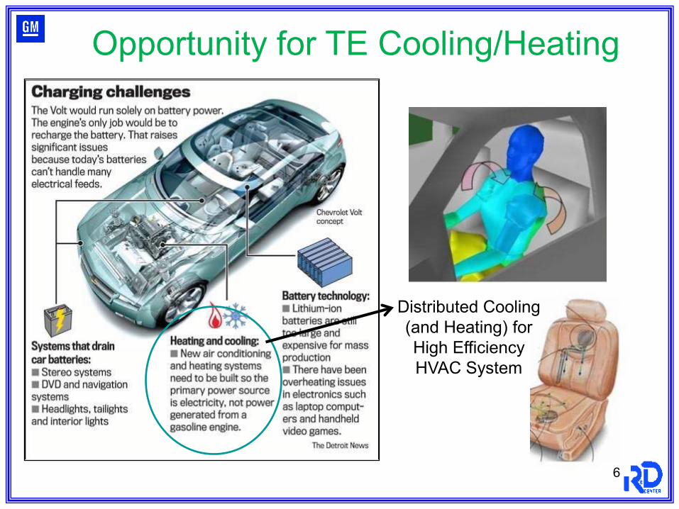
Opportunity for TE Cooling/Heating
Distributed Cooling (and Heating) for High Efficiency HVAC System
6
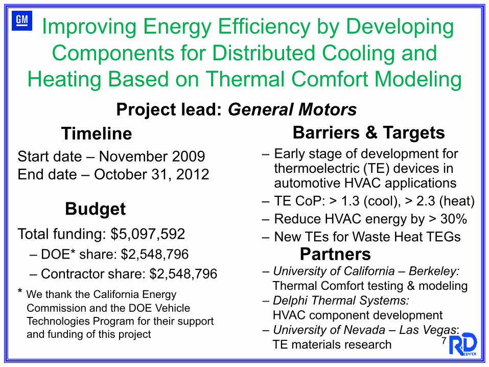
Improving Energy Efficiency by Developing Components for Distributed Cooling and
Heating Based on Thermal Comfort Modeling
Start date – November 2009End date – October 31, 2012
– Early stage of development for thermoelectric (TE) devices in automotive HVAC applications
– TE CoP: > 1.3 (cool), > 2.3 (heat)– Reduce HVAC energy by > 30%– New TEs for Waste Heat TEGs
Timeline
Budget
Barriers & Targets
PartnersTotal funding: $5,097,592
– DOE* share: $2,548,796– Contractor share: $2,548,796
* We thank the California Energy Commission and the DOE Vehicle Technologies Program for their support and funding of this project
– University of California – Berkeley:Thermal Comfort testing & modeling
– Delphi Thermal Systems:HVAC component development
– University of Nevada – Las Vegas:TE materials research
Project lead: General Motors
7
8
Introduction
H
CH
CH
TT
ZT
ZTT
TT
++
−+−=
1
11ε
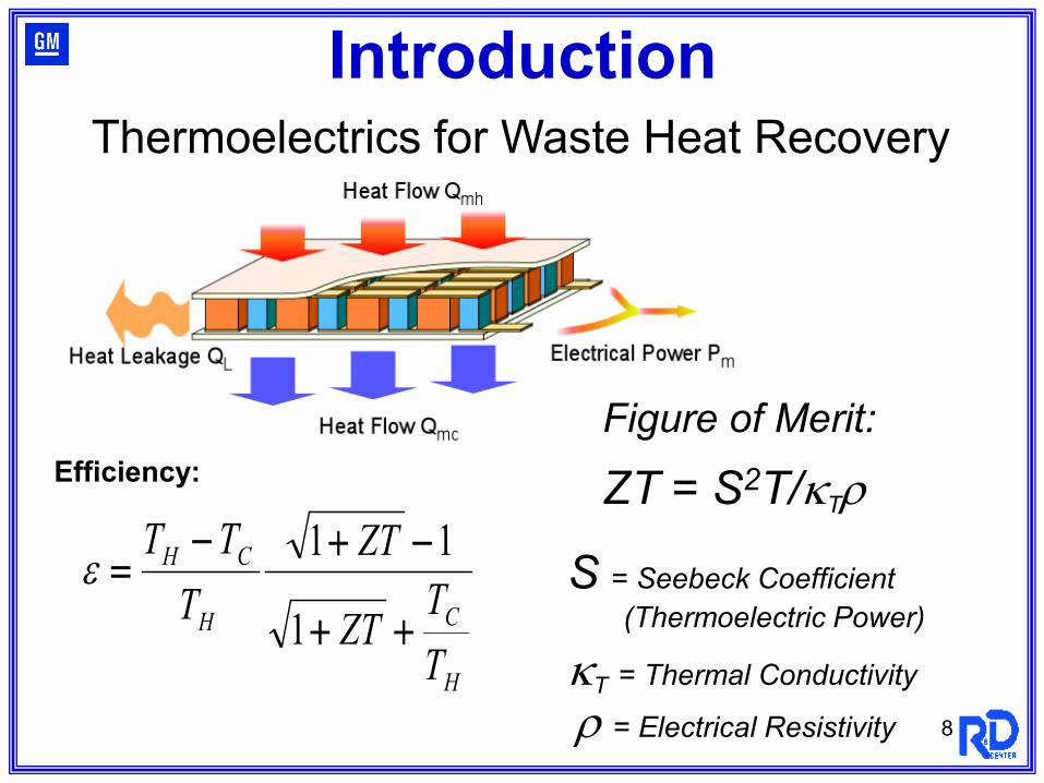
Efficiency:Figure of Merit:
ZT = S2T/κTρ
S = Seebeck Coefficient (Thermoelectric Power)
κT = Thermal Conductivity
ρ = Electrical Resistivity
Thermoelectrics for Waste Heat Recovery
9
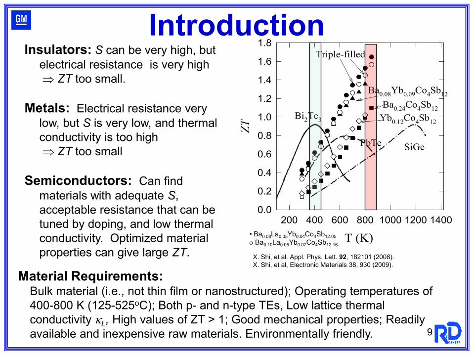
Insulators: S can be very high, but electrical resistance is very high⇒ ZT too small.
Metals: Electrical resistance verylow, but S is very low, and thermal conductivity is too high⇒ ZT too small
Semiconductors: Can find materials with adequate S, acceptable resistance that can be tuned by doping, and low thermal conductivity. Optimized material properties can give large ZT.
Material Requirements:Bulk material (i.e., not thin film or nanostructured); Operating temperatures of 400-800 K (125-525oC); Both p- and n-type TEs, Low lattice thermal conductivity κL, High values of ZT > 1; Good mechanical properties; Readily available and inexpensive raw materials. Environmentally friendly.
T (K)200 400 600 800 1000 1200 1400
ZT
0.0
0.2
0.4
0.6
0.8
1.0
1.2
1.4
1.6
1.8
Bi2Te3
PbTe SiGe
Ba0.24Co4Sb12
Ba0.08Yb0.09Co4Sb12
Triple-filled
Yb0.12Co4Sb12
• Ba0.08La0.05Yb0.04Co4Sb12.05ο Ba0.10La0.05Yb0.07Co4Sb12.16
X. Shi, et al. Appl. Phys. Lett. 92, 182101 (2008).X. Shi, et al, Electronic Materials 38, 930 (2009).
Introduction
10
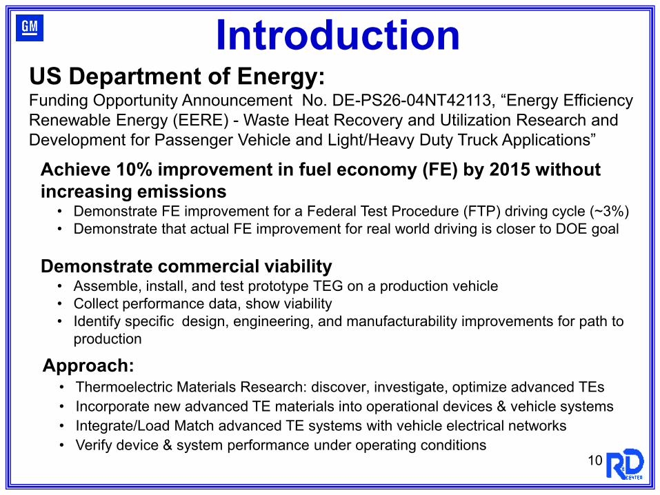
Approach:• Thermoelectric Materials Research: discover, investigate, optimize advanced TEs • Incorporate new advanced TE materials into operational devices & vehicle systems• Integrate/Load Match advanced TE systems with vehicle electrical networks• Verify device & system performance under operating conditions
US Department of Energy:Funding Opportunity Announcement No. DE-PS26-04NT42113, “Energy Efficiency Renewable Energy (EERE) - Waste Heat Recovery and Utilization Research and Development for Passenger Vehicle and Light/Heavy Duty Truck Applications”
Introduction
Achieve 10% improvement in fuel economy (FE) by 2015 without increasing emissions• Demonstrate FE improvement for a Federal Test Procedure (FTP) driving cycle (~3%)• Demonstrate that actual FE improvement for real world driving is closer to DOE goal
Demonstrate commercial viability • Assemble, install, and test prototype TEG on a production vehicle• Collect performance data, show viability• Identify specific design, engineering, and manufacturability improvements for path to
production
11
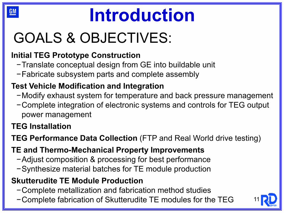
GOALS & OBJECTIVES:Initial TEG Prototype Construction−Translate conceptual design from GE into buildable unit−Fabricate subsystem parts and complete assembly
Test Vehicle Modification and Integration−Modify exhaust system for temperature and back pressure management−Complete integration of electronic systems and controls for TEG output
power managementTEG InstallationTEG Performance Data Collection (FTP and Real World drive testing)TE and Thermo-Mechanical Property Improvements−Adjust composition & processing for best performance−Synthesize material batches for TE module production
Skutterudite TE Module Production −Complete metallization and fabrication method studies−Complete fabrication of Skutterudite TE modules for the TEG
Introduction
GM R&D Thermoelectrics Team:Researchers:
Jim SalvadorJihui YangMike Reynolds
Postdocs:Xun Shi, Jung Cho, Zuxin Ye
Engineering Operations:Kevin RoberJohn Manole
Gov. Contracts:Ed Gundlach, Amanda DemitrishRick Leach
Management:Jan HerbstMark Verbrugge
GMPT Integration & Testing:Greg Prior (Retired)Joshua Cowgill
Collaborators/Subcontractors:Marlow Industries: Jeff Sharp,
Jim Bierschenk, Josh Moczygemba
Oak Ridge National Laboratory:Hsin Wang, Andy Wereszczak
University of Nevada, Las Vegas:Changfeng Chen, Yi Zhang
Future Tech: Francis Stabler
Heat Technology, IncEmcon (Faurecia)Shanghai Institute of Ceramics: Lidong Chen
University of Michigan: Ctirad Uher
University of South Florida: George Nolas
Brookhaven National Laboratory: Qiang Li
Michigan State University: Don Morelli
General Electric Global Research:Todd Anderson, Peter DeBock
Acknowledgements
12
U.S. Department of Energy Grant # DE-FC26-04NT 42278 John Fairbanks (DOE), Carl Maronde (NETL)
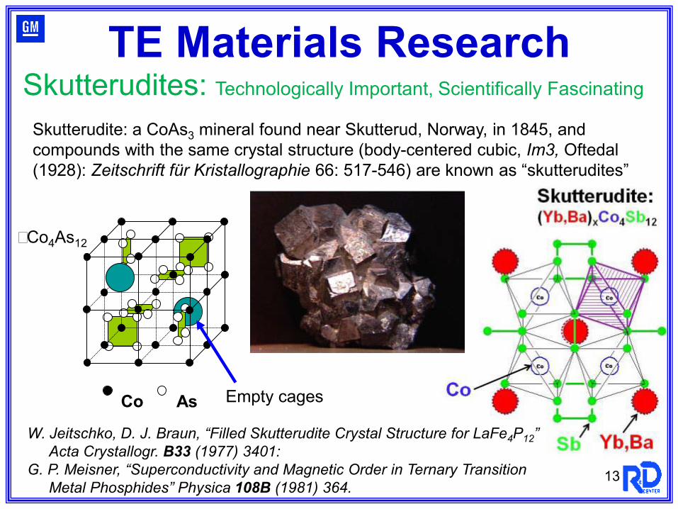
Skutterudite: a CoAs3 mineral found near Skutterud, Norway, in 1845, and compounds with the same crystal structure (body-centered cubic, Im3, Oftedal (1928): Zeitschrift für Kristallographie 66: 517-546) are known as “skutterudites”
13
Skutterudites: Technologically Important, Scientifically Fascinating
Co As
�Co4As12
Empty cages
W. Jeitschko, D. J. Braun, “Filled Skutterudite Crystal Structure for LaFe4P12” Acta Crystallogr. B33 (1977) 3401:
G. P. Meisner, “Superconductivity and Magnetic Order in Ternary Transition Metal Phosphides” Physica 108B (1981) 364.
TE Materials Research
14
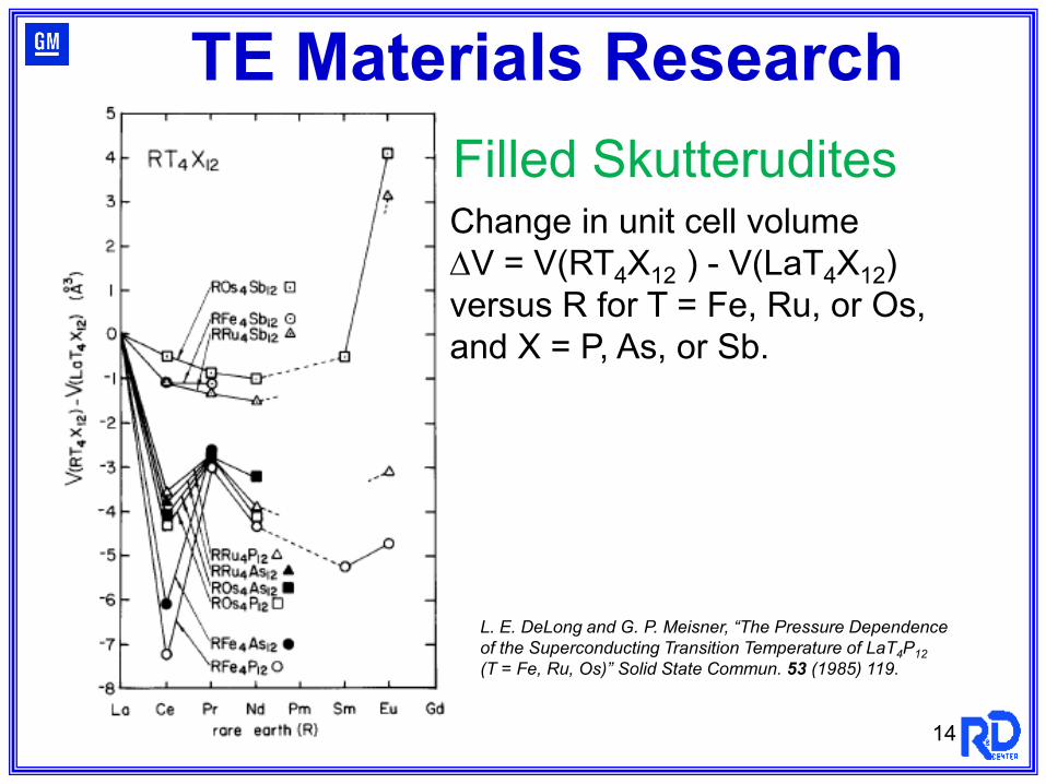
L. E. DeLong and G. P. Meisner, “The Pressure Dependence of the Superconducting Transition Temperature of LaT4P12(T = Fe, Ru, Os)” Solid State Commun. 53 (1985) 119.
Change in unit cell volume ∆V = V(RT4X12 ) - V(LaT4X12)versus R for T = Fe, Ru, or Os, and X = P, As, or Sb.
Filled Skutterudites
TE Materials Research
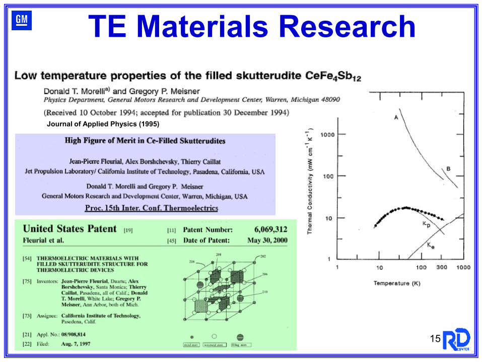
Journal of Applied Physics (1995)
15
TE Materials Research
16
T (K)200 400 600 800 1000 1200 1400
ZT
0.0
0.2
0.4
0.6
0.8
1.0
1.2
1.4
1.6
1.8
Bi2Te3
PbTe SiGe
Ba0.24Co4Sb12
Ba0.08Yb0.09Co4Sb12
Triple-filled
Yb0.12Co4Sb12
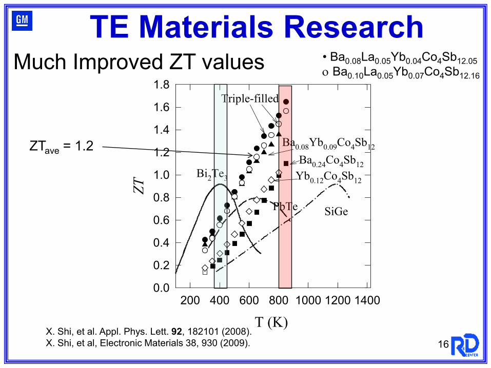
ZTave = 1.2
• Ba0.08La0.05Yb0.04Co4Sb12.05ο Ba0.10La0.05Yb0.07Co4Sb12.16
Much Improved ZT values
X. Shi, et al. Appl. Phys. Lett. 92, 182101 (2008).X. Shi, et al, Electronic Materials 38, 930 (2009).
TE Materials Research
17
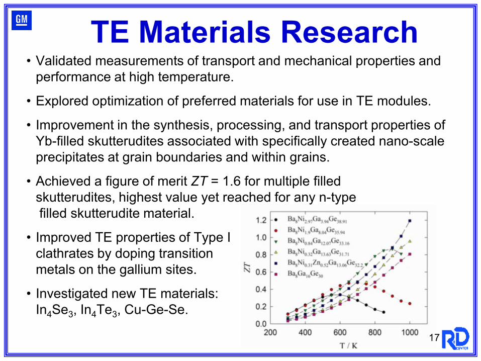
• Validated measurements of transport and mechanical properties and performance at high temperature.
• Explored optimization of preferred materials for use in TE modules.
• Improvement in the synthesis, processing, and transport properties of Yb-filled skutterudites associated with specifically created nano-scale precipitates at grain boundaries and within grains.
• Achieved a figure of merit ZT = 1.6 for multiple filled skutterudites, highest value yet reached for any n-typefilled skutterudite material.
• Improved TE properties of Type I clathrates by doping transition metals on the gallium sites.
• Investigated new TE materials: In4Se3, In4Te3, Cu-Ge-Se.
TE Materials Research
18
2010 Publications/Presentations 1. Shi, X.; Yang, Jiong; Bai, S. Q.; Yang, Jihui; Salvador, J. R.; Wang, H.; Chi, M.; Zhang, W. Q.; Chen, L.; Wong-Ng, W.
“On the Design of High Efficiency Thermoelectric Clathrates through a Systematic Cross-substitution of Framework Elements”, Adv. Funct. Mater. 20, 755 (2010).
2. Beekman, M., Shi, X., Salvador, J. R., Nolas, G. S., and Yang, J., "Characterization of delafossite-type CuCoO2 prepared by ion exchange", J. Alloys Compounds 489, 336 (2010).
3. Cho, J. Y.; Shi, X.; Salvador, J. R.; Yang, J.; and Wang, H.; “Thermoelectric properties of ternary diamond-like semiconductors Cu2Ge1+xSe3”, J. Appl. Phys. 108, 073713 (2010).
4. Shi, X.; Cho, J.; Salvador, J. R.; Yang, J.; Wang, H.; “Thermoelectric properties of polycrystalline In4Se3 and In4Te3”, Appl. Phys. Lett. 96, 162108 (2010).
5. Salvador, J. R.; Yang, J.; Wang, H.; Shi, X.; “Double-filled skutterudites of the type YbxCayCo4Sb12: Synthesis and Properties,” J. Appl. Phys. 107, 043705 (2010).
6. Meisner, G. P.: “Materials and Engineering for Automotive Thermoelectric Applications,” Global Powertrain Congress, Troy, MI, November 2009 (Invited).
7. Salvador, J. R.; “Engineering and Materials for Automotive Thermoelectric Applications,” U.S. Car, Troy MI, March 3, 2010 (Invited).
8. Yang, J.; “Neutron Scattering Studies of Thermoelectric Materials for Automotive Applications” American Physical Society Meeting, Portland, OR, March 2010. (Invited).
9. Yang, J.; “Thermoelectric Materials by Design,” 29th International Conference on Thermoelectrics, Shanghai, China, May 2010 (Invited).
10.Meisner, G. P.; “Automotive Waste Heat Recovery Using Advanced Thermoelectrics,” Complex and Nanostructured Materials for Energy Applications Conference, Michigan State University, Lansing, MI, June 2010 (Invited).
11.Meisner, G. P.; “Improving Energy Efficiency by Developing Components for Distributed Cooling and Heating Based on Thermal Comfort Modeling,” Vehicle Technologies Program Annual Merit Review Meeting, U.S. Department of Energy, Washington, DC, June 2010.
12.Meisner, G. P.; “Develop Thermoelectric Technology for Automotive Waste Heat Recovery,” Vehicle Technologies Program Annual Merit Review Meeting, U.S. Department of Energy, Washington, DC, June 2010.
13.Meisner, G. P.; “Thermoelectric Generator Development for Automotive Waste Heat Recovery,” 16th Directions in Engine Efficiency & Emissions Research (DEER) Conference, Detroit, MI, September 2010.
14.Yang, J.; “Advanced Materials for Future Propulsion”. 2010 Frontiers of Renewable Energy Sciences & Technologies Conference, Harvard University, Cambridge, MA, September 2010 (Invited).
19
2010 Publications/Presentations (Cont.) 15.Yang, J.; “Advanced Materials for Future Propulsion”. 2010 Frontiers of Renewable Energy Sciences & Technologies
Conference, Harvard University, Cambridge, MA, September 2010 (Invited).16.Salvador, J. R.; “Engineering and Materials for Automotive Thermoelectric Applications,” Global Powertrain Congress,
Troy, MI, November 2010 (Invited).17.Yang, J. Shi, X.; Wang, H.; Chi, M.; Salvador, J. R.; Yang, Jiong; Bai, S.; Zhang, W. Q.; Chen, L.; Copley, J. R.; Leao, J.;
Rush, J. J.; “Are Skutterudites Phonon Crystals or Phonon Glasses,” Materials Research Society Fall Meeting, Boston, MA, December 2010 (Invited).
18.Meisner, G. P.; “Progress on Thermoelectric Generator Development for Automotive Exhaust Gas Waste Heat Recovery,” Materials Research Society Fall Meeting, Boston, MA, December 2010.
19.Salvador, J. R.; “Mechanical and Elastic Property Evaluation of n and p-type Skutterudites,” Materials Research Society Fall Meeting, Boston, MA, December 2010.
20.Cho, J. Y.; Salvador, J. R.; Wang, H.; Wereszcak, A. A.; Chi, M.; ‘Thermoelectric Properties of Diamond-like Compounds Cu2GaxGe1+xSe3 (x = 0 ~ 0.1),” Materials Research Society Fall Meeting, Boston, MA, December 2010.
ROIs/Patents1. “Filled Skutterudites for Advanced Thermoelectric Applications,” Yang, J.; Meisner, G. P.; U.S. Patent 7648552 Issued
January 19, 2010.2. “Optimal power determination for a Thermoelectric Generator by setpoint dithering,” Reynolds, M. G.; Cowgill, J. D.;
P011627, Record of Invention submitted January 29, 2010.3. “Algorithms for Bypass Valve and Coolant Flow Controls for Optimum Temperatures in Waste Heat Recovery Systems,”
Meisner, G. P.; P012265, Record of Invention submitted April 8, 2010.4. “Method of Controlling Temperature of a Thermoelectric Generator in an Exhaust System.” Prior, G. P.; Reynolds, M. G.;
Cowgill, J. D.; P011519, U.S. Patent Application filed April 2, 2010.5. “Thermoelectric Generator Cooling System and Method of Control,” Prior, G. P.; Meisner, G. P.; Glassford, D. B.;
P011552-R&D, U.S. Patent Application Filed April 2, 2010.6. “Formation of Thermoelectric Elements by Net Shape Sintering” Salvador, J. R.; Yang, J.; Wereszczak, A. A.; P009885-
R&D, U.S. Patent Application Filed June 4, 2010.7. “Thermoelectric Generators for Waste Heat Recovery from Engine Exhaust,” Meisner, G. P.; Yang, J.; P012262, U.S.
Patent Application filed September 2010.
20
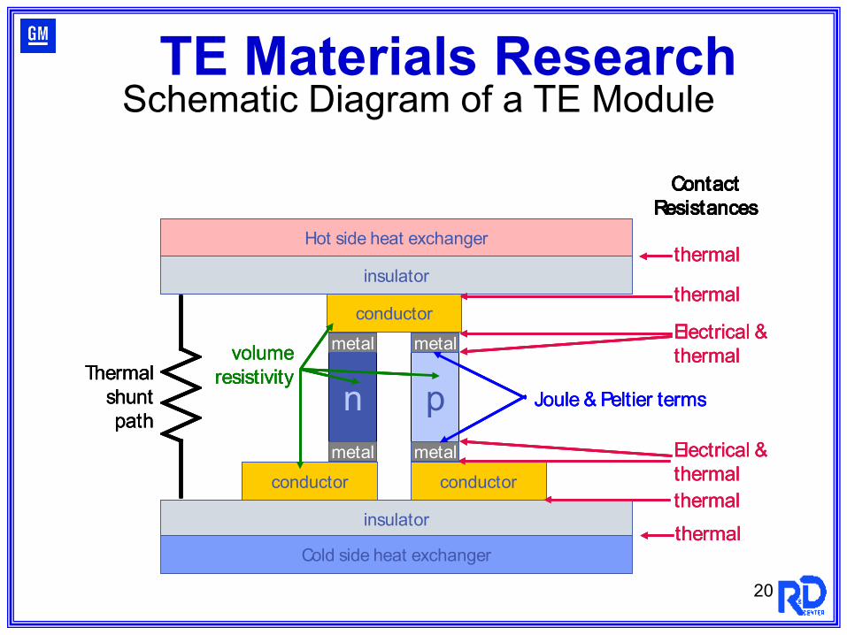
n p
metal
metalmetal
metal
conductor
ContactResistances
conductor conductor
insulator
insulator
Hot side heat exchanger
Cold side heat exchanger
thermal
thermal
Electrical &thermal
thermal
thermal
volumeresistivity
Electrical &thermal
Thermal shunt path
Joule & Peltier terms
n p
metal
metalmetal
metal
conductor
ContactResistances
conductor conductor
insulator
insulator
Hot side heat exchanger
Cold side heat exchanger
thermal
thermal
Electrical &thermal
thermal
thermal
volumeresistivity
Electrical &thermal
Thermal shunt path
Joule & Peltier termsn p
metal
metalmetal
metal
conductor
ContactResistances
conductor conductor
insulator
insulator
Hot side heat exchanger
Cold side heat exchanger
thermal
thermal
Electrical &thermal
thermal
thermal
volumeresistivity
Electrical &thermal
Thermal shunt path
Joule & Peltier terms
TE Materials ResearchSchematic Diagram of a TE Module
21
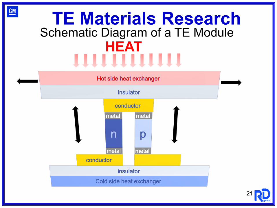
n p
metal
metalmetal
metal
conductor
conductor
insulator
insulator
Hot side heat exchanger
Cold side heat exchanger
n p
metal
metalmetal
metal
conductor
conductor
insulator
insulator
Hot side heat exchanger
Cold side heat exchanger
n p
metal
metalmetal
metal
conductor
conductor
insulator
insulator
Hot side heat exchanger
Cold side heat exchanger
Schematic Diagram of a TE Module HEAT
TE Materials Research
22
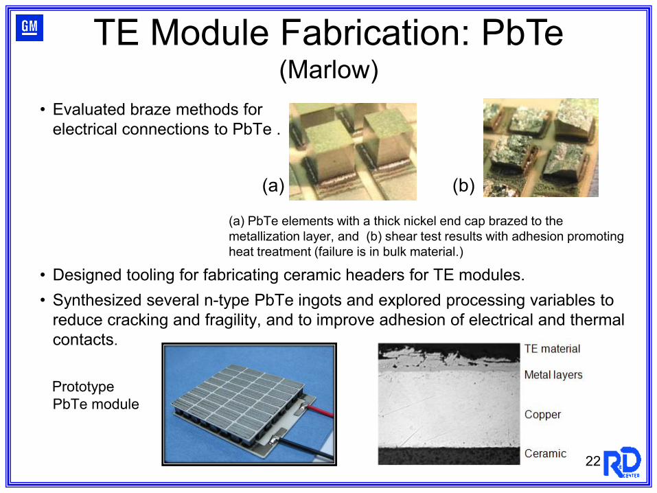
• Evaluated braze methods for electrical connections to PbTe .
(a) PbTe elements with a thick nickel end cap brazed to the metallization layer, and (b) shear test results with adhesion promoting heat treatment (failure is in bulk material.)
• Designed tooling for fabricating ceramic headers for TE modules.• Synthesized several n-type PbTe ingots and explored processing variables to
reduce cracking and fragility, and to improve adhesion of electrical and thermal contacts.
PrototypePbTe module
TE Module Fabrication: PbTe(Marlow)
(a) (b)
23
Incorporate New Advanced TE materials into Operational Devices & Vehicle SystemsImprove TE materials (Skutterudites) (ZT = 1.6 at 850 K, ZTave= 1.2)
Develop models and computational tools to design TE generators (TEGs) which include heat transfer physics at heat exchanger and interfaces; TE material properties; mechanical reliability, and cost
Develop thermoelectric modules for TEG
Finalize design, fabricate, and assemble prototype TEG
Complete vehicle modification for controls and integration of TEG
Develop power electronics design for power conditioning
Develop system control algorithms for improved thermal-to-electrical conversion efficiency
Assess TEG performance
TE Generator Development
Exhaust Heat - City Driving Cycle
0
10
20
30
40
50
60
70
80
0 500 1000 1500 2000 2500
Test Time (s)
kW
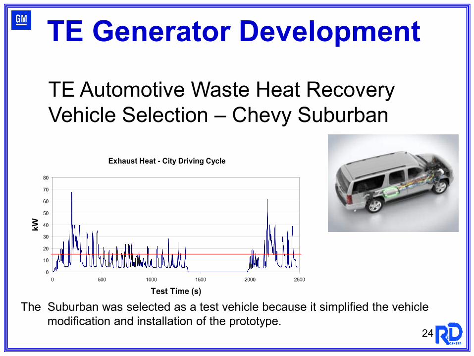
The Suburban was selected as a test vehicle because it simplified the vehicle modification and installation of the prototype.
TE Automotive Waste Heat Recovery Vehicle Selection – Chevy Suburban
24
TE Generator Development

The Suburban was selected as a test vehicle because it simplified the vehicle modification and installation of the prototype.
TE Automotive Waste Heat Recovery Vehicle Selection – Chevy Suburban
25
TE Generator Development
-100
0
100
200
300
400
500
600
700
800
900
0 500 1000 1500 2000 2500
Test Time (s)
deg
C
0
10
20
30
40
50
60
70
80
90
100
MPH
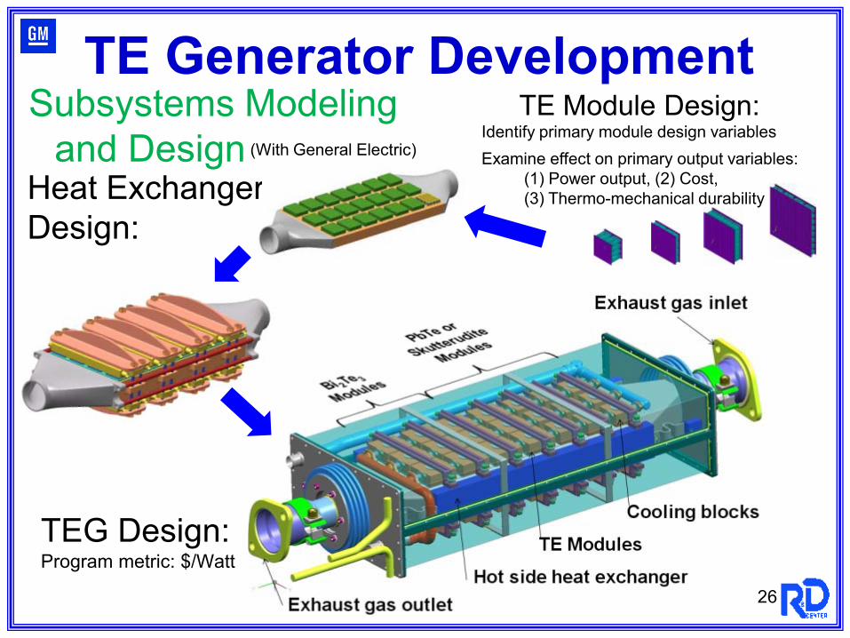
TE Module Design:
Heat ExchangerDesign:
26
Identify primary module design variablesExamine effect on primary output variables:
(1) Power output, (2) Cost, (3) Thermo-mechanical durability
TEG Design:Program metric: $/Watt
Subsystems Modelingand Design (With General Electric)
TE Generator Development
27
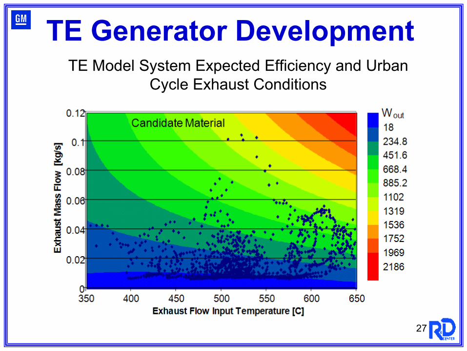
TE Model System Expected Efficiency and Urban Cycle Exhaust Conditions
TE Generator Development
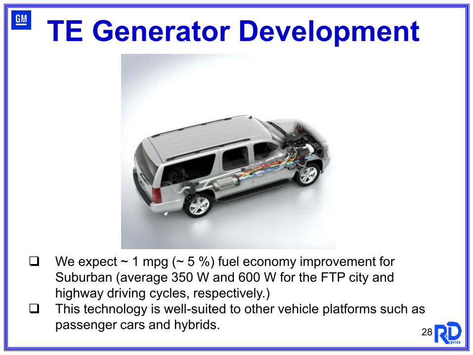
We expect ~ 1 mpg (~ 5 %) fuel economy improvement for Suburban (average 350 W and 600 W for the FTP city and highway driving cycles, respectively.)
This technology is well-suited to other vehicle platforms such as passenger cars and hybrids. 28
TE Generator Development
29
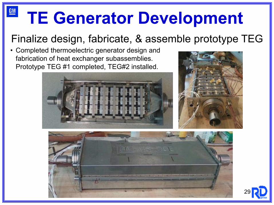
• Completed thermoelectric generator design and fabrication of heat exchanger subassemblies.Prototype TEG #1 completed, TEG#2 installed.
Finalize design, fabricate, & assemble prototype TEG
TE Generator Development
30
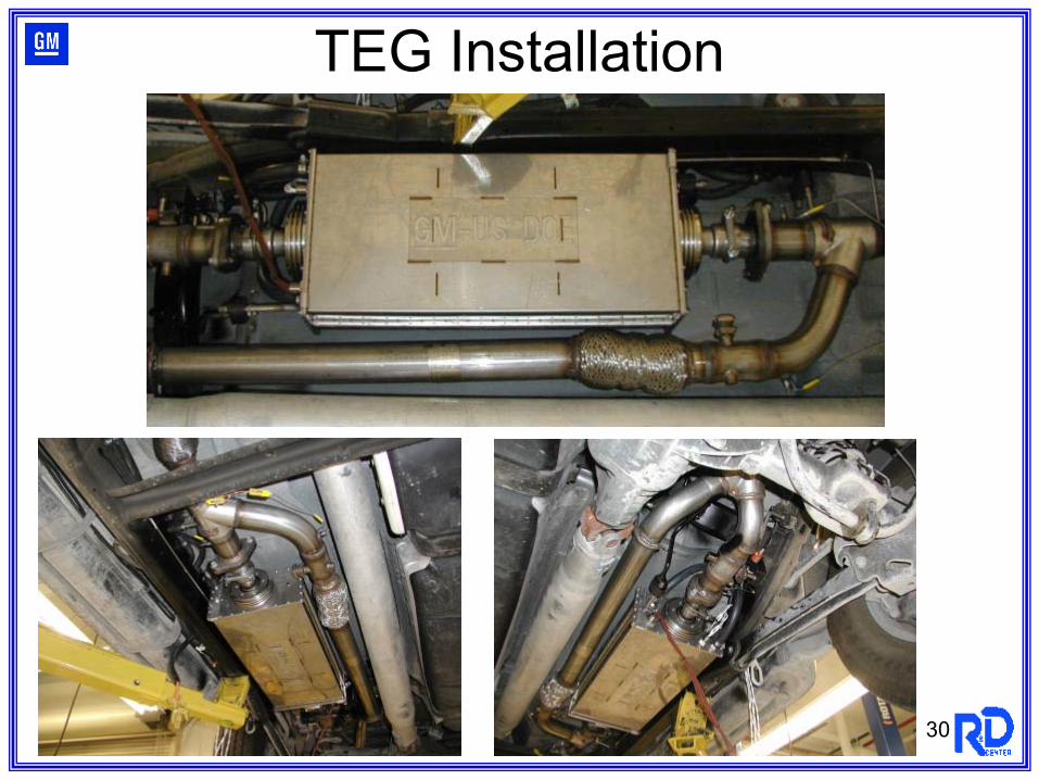
TEG Installation
31
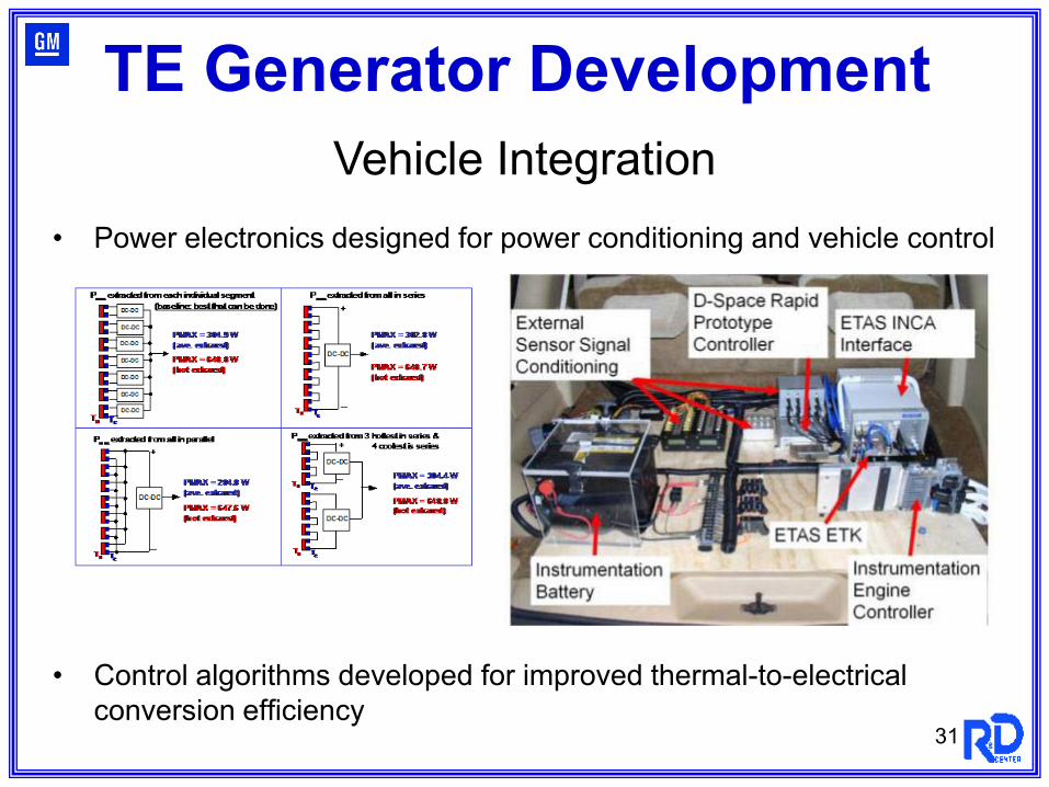
• Power electronics designed for power conditioning and vehicle control
• Control algorithms developed for improved thermal-to-electrical conversion efficiency
Vehicle Integration
TE Generator Development
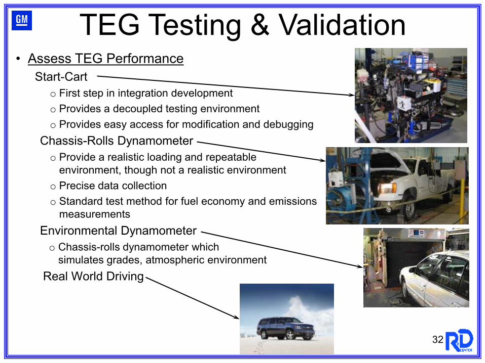
• Assess TEG PerformanceStart-Cart
o First step in integration developmento Provides a decoupled testing environmento Provides easy access for modification and debugging
Chassis-Rolls Dynamometero Provide a realistic loading and repeatable
environment, though not a realistic environmento Precise data collectiono Standard test method for fuel economy and emissions
measurementsEnvironmental Dynamometero Chassis-rolls dynamometer which
simulates grades, atmospheric environmentReal World Driving
32
TEG Testing & Validation
33
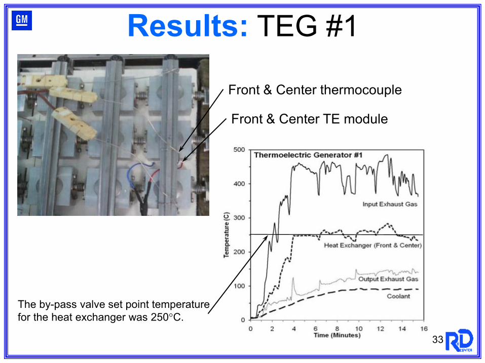
Results: TEG #1
Front & Center thermocouple
Front & Center TE module
The by-pass valve set point temperature for the heat exchanger was 250°C.
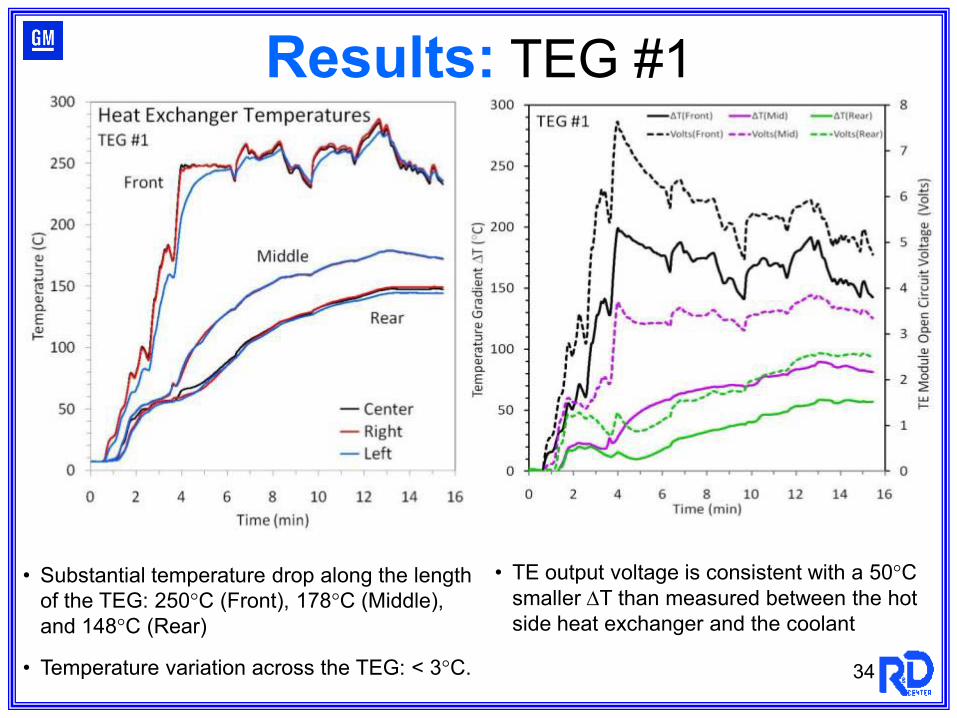
• Substantial temperature drop along the length of the TEG: 250°C (Front), 178°C (Middle), and 148°C (Rear)
• Temperature variation across the TEG: < 3°C.
• TE output voltage is consistent with a 50°C smaller ∆T than measured between the hot side heat exchanger and the coolant
Results: TEG #1
34
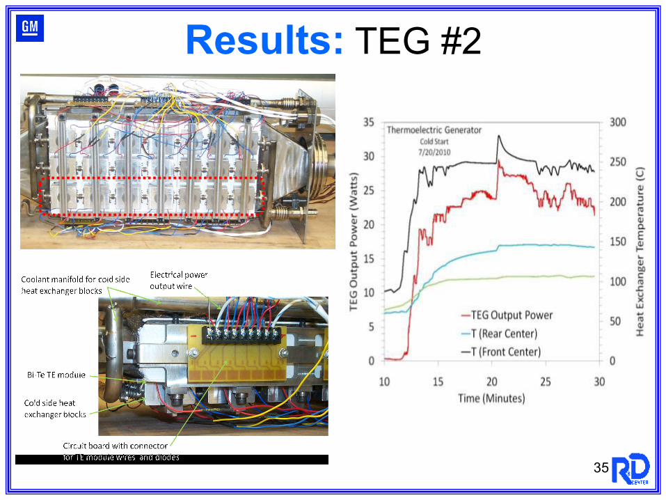
Results: TEG #2
35
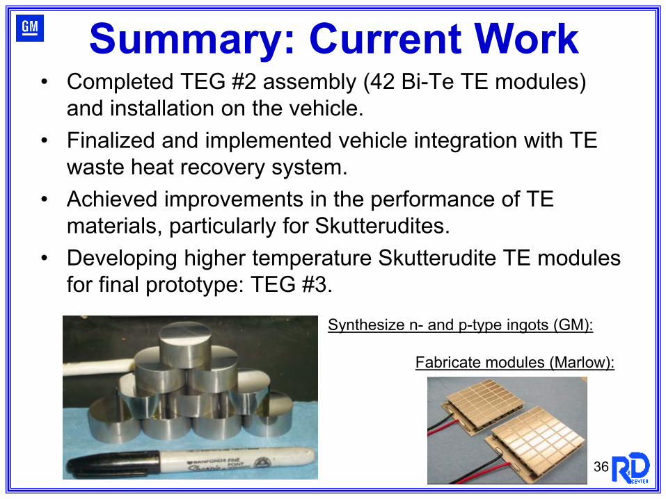
• Completed TEG #2 assembly (42 Bi-Te TE modules) and installation on the vehicle.
• Finalized and implemented vehicle integration with TE waste heat recovery system.
• Achieved improvements in the performance of TE materials, particularly for Skutterudites.
• Developing higher temperature Skutterudite TE modules for final prototype: TEG #3.
Summary: Current Work
Synthesize n- and p-type ingots (GM):
Fabricate modules (Marlow):
36
37
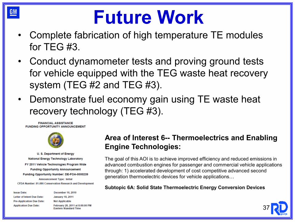
• Complete fabrication of high temperature TE modules for TEG #3.
• Conduct dynamometer tests and proving ground tests for vehicle equipped with the TEG waste heat recovery system (TEG #2 and TEG #3).
• Demonstrate fuel economy gain using TE waste heat recovery technology (TEG #3).
Future Work
Area of Interest 6-- Thermoelectrics and Enabling Engine Technologies:The goal of this AOI is to achieve improved efficiency and reduced emissions in advanced combustion engines for passenger and commercial vehicle applications through: 1) accelerated development of cost competitive advanced second generation thermoelectric devices for vehicle applications…
Subtopic 6A: Solid State Thermoelectric Energy Conversion Devices