Embed Size (px)
Citation preview

Programmer’s Guide
Publication number 01660-97033Second edition, January 2000
For Safety information, Warranties, and Regulatory
information, see the pages behind the index
Copyright Agilent Technologies 1992-2000 All Rights Reserved
Agilent Technologies1660A/AS-Series LogicAnalyzers
Advanced Test Equipment Rentalswww.atecorp.com 800-404-ATEC (2832)
®
Established 1981

ii

In This Book
This programmer’s guide contains generalinformation, mainframe level commands,logic analyzer commands, oscilloscopemodule commands, and programmingexamples for programming the1660-series logic analyzers. This guidefocuses on how to program theinstrument over the GPIB and theRS-232C interfaces.
Instruments covered by the
1660-Series Programmer’s Guide
The 1660-series logic analyzers areavailable with or without oscilloscopemeasurement capabilities. The1660A-series logic analyzers contain onlya logic analyzer. The 1660AS-series logicanalyzers contain both a logic analyzerand a digitizing oscilloscope.
What is in the 1660-Series
Programmer’s Guide?
The 1660-Series Programmer’s Guide
is organized in five parts.
Part 1 Part 1 consists of chapters 1through 7 and contains generalinformation about programming basics,GPIB and RS-232C interfacerequirements, documentationconventions, status reporting , and errormessages.
Introduction to Programming1
Programming Over GPIB2
Programming Over RS-232C3
Programming and Documentation Conventions4
Message Communication and System Functions5
Status Reporting6
Error Message7
Common Commands8
Mainframe Commands9
SYSTem Subsystem10
MMEMory Subsystem11
INTermodule Subsystem12
MACHine Subsystem13
WLISt Subsystem14
iii
If you are already familiar with IEEE 488.2 programming and GPIB orRS-232C, you may want to just scan these chapters. If you are new toprogrammiung the system, you should read part 1.
Chapter 1 is divided into two sections. The first section, "Talking to theInstrument," concentrates on program syntax, and the second section,"Receiving Information from the Instrument," discusses how to send queriesand how to retrieve query results from the instrument.
Read either chapter 2, "Programming Over GPIB," or chapter 3,"Programming Over RS-232C" for information concerning the physicalconnection between the 1660-series logic analyzer and your controller.
Chapter 4, "Programming and Documentation Conventions," gives anoverview of all instructions and also explains the notation conventions usedin the syntax definitions and examples.
Chapter 5, "Message Communication and System Functions," provides anoverview of the operation of instruments that operate in compliance with theIEEE 488.2 standard.
Chapter 6 explains status reporting and how it can be used to monitor theflow of your programs and measurement process.
Chapter 7 contains error message descriptions.
Part 2 Part 2, chapters 8 through 12, explain each command in thecommand set for the mainframe. These chapters are organized insubsystems with each subsystem representing a front-panel menu.
The commands explained in this part give you access to common commands,mainframe commands, system level commands, disk commands, andintermodule measurement commands. This part is designed to provide aconcise description of each command.
Part 3 Part 3, chapters 13 through 25 explain each command in thesubsystem command set for the logic analyzer. Chapter 26 containsinformation on the SYSTem:DATA and SYSTem:SETup commands forthe logic analyzer.
The commands explained in this part give you access to all the commandsused to operate the logic analyzer portion of the 1660-series system. Thispart is designed to provide a concise description of each command.
Part 4 Part 4, chapters 27 through 35 explain each command in thesubsystem command set for the oscilloscope.
iv

The commands explained in this part giveyou access to all the commands used tooperate the oscilloscope portion of the1660-series system. This part is designedto provide a concise description of eachcommand.
Part 5 Part 5, chapter 36 containsprogram examples of actual tasks thatshow you how to get started inprogramming the 1660-series logicanalyzers. The complexity of yourprograms and the tasks they accomplishare limited only by your imagination.These examples are written in HP BASIC6.2; however, the program concepts canbe used in any other popularprogramming language that allowscommunications over GPIB or RS-232buses.
SFORmat Subsystem15
STRigger (STRace) Subsystem16
SLISt Subsystem17
SWAVeform Subsystem18
SCHart Subsystem19
COMPare Subsystem20
TFORmat Subsystem21
TRIGger {TRACe} Subsystem22
TWAVeform Subsystem23
TLISt Subsystem24
SYMbol Subsystem25
DATA and SETup Commands26
Oscilloscope Root LevelCommands27
ACQuire Subsystem28
v

vi

CHANnel Subsystem29
DISPlay Subsystem30
MARKer Subsystem31
MEASure Subsystem32
TIMebase Subsystem33
TRIGger Subsystem34
WAVeform Subsystem35
Programming Examples36
Index
vii

viii

Contents
Part 1 General Information
1 Introduction to Programming
Talking to the Instrument 1–3
Initialization 1–4Instruction Syntax 1–5Output Command 1–5Device Address 1–6Instructions 1–6Instruction Terminator 1–7Header Types 1–8Duplicate Keywords 1–9Query Usage 1–10Program Header Options 1–11Parameter Data Types 1–12Selecting Multiple Subsystems 1–14
Receiving Information from the Instrument 1–15
Response Header Options 1–16Response Data Formats 1–17String Variables 1–18Numeric Base 1–19Numeric Variables 1–19Definite-Length Block Response Data 1–20Multiple Queries 1–21Instrument Status 1–22
2 Programming Over GPIB
Interface Capabilities 2–3Command and Data Concepts 2–3Addressing 2–3Communicating Over the GPIB Bus (HP 9000 Series 200/300 Controller) 2–4Local, Remote, and Local Lockout 2–5Bus Commands 2–6
Contents–1

3 Programming Over RS-232C
Interface Operation 3–3RS-232C Cables 3–3Minimum Three-Wire Interface with Software Protocol 3–4Extended Interface with Hardware Handshake 3–4 Cable Examples 3–6Configuring the Logic Analzer Interface 3–8Interface Capabilities 3–9RS-232C Bus Addressing 3–10Lockout Command 3–11
4 Programming and Documentation Conventions
Truncation Rule 4–3Infinity Representation 4–4Sequential and Overlapped Commands 4–4Response Generation 4–4Syntax Diagrams 4–4Notation Conventions and Definitions 4–5The Command Tree 4–5Tree Traversal Rules 4–6Command Set Organization 4–14Subsystems 4–15Program Examples 4–16
5 Message Communication and System Functions
Protocols 5–3Syntax Diagrams 5–5Syntax Overview 5–7
6 Status Reporting
Event Status Register 6–4Service Request Enable Register 6–4Bit Definitions 6–4Key Features 6–6Serial Poll 6–7
Contents
Contents–2
7 Error Messages
Device Dependent Errors 7–3Command Errors 7–3Execution Errors 7–4Internal Errors 7–4Query Errors 7–5
Part 2 Mainframe Commands
8 Common Commands
*CLS (Clear Status) 8–5*ESE (Event Status Enable) 8–6*ESR (Event Status Register) 8–7*IDN (Identification Number) 8–9*IST (Individual Status) 8–9*OPC (Operation Complete) 8–11*OPT (Option Identification) 8–12*PRE (Parallel Poll Enable Register Enable) 8–13*RST (Reset) 8–14*SRE (Service Request Enable) 8–15*STB (Status Byte) 8–16*TRG (Trigger) 8–17*TST (Test) 8–18*WAI (Wait) 8–19
9 Mainframe Commands
BEEPer 9–6CAPability 9–7CARDcage 9–8CESE (Combined Event Status Enable) 9–9CESR (Combined Event Status Register) 9–10EOI (End Or Identify) 9–11LER (LCL Event Register) 9–11LOCKout 9–12MENU 9–12
Contents
Contents–3

MESE<N> (Module Event Status Enable) 9–14MESR<N> (Module Event Status Register) 9–16RMODe 9–18RTC (Real-time Clock) 9–19SELect 9–20SETColor 9–22STARt 9–23STOP 9–24
10 SYSTem Subsystem
DATA 10–5DSP (Display) 10–6ERRor 10–7HEADer 10–8LONGform 10–9PRINt 10–10SETup 10–11
11 MMEMory Subsystem
AUToload 11–8CATalog 11–9COPY 11–10DOWNload 11–11INITialize 11–13LOAD [:CONFig] 11–14LOAD :IASSembler 11–15MSI (Mass Storage Is) 11–16PACK 11–17PURGe 11–17REName 11–18STORe [:CONFig] 11–19UPLoad 11–20VOLume 11–21
Contents
Contents–4

12 INTermodule Subsystem
:INTermodule 12–5DELete 12–5HTIMe 12–6INPort 12–6INSert 12–7SKEW<N> 12–8TREE 12–9TTIMe 12–10
Part 3 Logic Analyzer Commands
13 MACHine Subsystem
MACHine 13–4ARM 13–5ASSign 13–5LEVelarm 13–6NAME 13–7REName 13–8RESource 13–9TYPE 13–10
14 WLISt Subsystem
WLISt 14–4DELay 14–5INSert 14–6LINE 14–7OSTate 14–8OTIMe 14–8RANGe 14–9REMove 14–10XOTime 14–10XSTate 14–11XTIMe 14–11
Contents
Contents–5

15 SFORmat Subsystem
SFORmat 15–6CLOCk 15–6LABel 15–7MASTer 15–9MODE 15–10MOPQual 15–11MQUal 15–12REMove 15–13SETHold 15–13SLAVe 15–15SOPQual 15–16SQUal 15–17THReshold 15–18
16 STRigger (STRace) Subsystem
Qualifier 16–7STRigger (STRace) 16–9ACQuisition 16–9BRANch 16–10CLEar 16–12FIND 16–13RANGe 16–14SEQuence 16–16STORe 16–17TAG 16–18TAKenbranch 16–19TCONtrol 16–20TERM 16–21TIMER 16–22TPOSition 16–23
17 SLISt Subsystem
SLISt 17–7COLumn 17–7
Contents
Contents–6

CLRPattern 17–8DATA 17–9LINE 17–9MMODe 17–10OPATtern 17–11OSEarch 17–12OSTate 17–13OTAG 17–13OVERlay 17–14REMove 17–15RUNTil 17–15TAVerage 17–17TMAXimum 17–17TMINimum 17–18VRUNs 17–18XOTag 17–19XOTime 17–19XPATtern 17–20XSEarch 17–21XSTate 17–22XTAG 17–22
18 SWAVeform Subsystem
SWAVeform 18–4ACCumulate 18–5ACQuisition 18–5CENTer 18–6CLRPattern 18–6CLRStat 18–7DELay 18–7INSert 18–8RANGe 18–8REMove 18–9TAKenbranch 18–9TPOSition 18–10
Contents
Contents–7

19 SCHart Subsystem
SCHart 19–4ACCumulate 19–4HAXis 19–5VAXis 19–7
20 COMPare Subsystem
COMPare 20–4CLEar 20–5CMASk 20–5COPY 20–6DATA 20–7FIND 20–9LINE 20–10MENU 20–10RANGe 20–11RUNTil 20–12SET 20–13
21 TFORmat Subsystem
TFORmat 21–4ACQMode 21–5LABel 21–6REMove 21–7THReshold 21–8
22 TTRigger (TTRace) Subsystem
Qualifier 22–6TTRigger (TTRace) 22–8ACQuisition 22–9BRANch 22–9CLEar 22–12FIND 22–13GLEDge 22–14RANGe 22–15
Contents
Contents–8

SEQuence 22–17SPERiod 22–18TCONtrol 22–19TERM 22–20TIMER 22–21TPOSition 22–22
23 TWAVeform Subsystem
TWAVeform 23–7ACCumulate 23–7ACQuisition 23–8CENTer 23–8CLRPattern 23–9CLRStat 23–9DELay 23–9INSert 23–10MMODe 23–11OCONdition 23–12OPATtern 23–13OSEarch 23–14OTIMe 23–15RANGe 23–16REMove 23–16RUNTil 23–17SPERiod 23–18TAVerage 23–19TMAXimum 23–19TMINimum 23–20TPOSition 23–20VRUNs 23–21XCONdition 23–22XOTime 23–22XPATtern 23–23XSEarch 23–24XTIMe 23–25
Contents
Contents–9

24 TLISt Subsystem
TLISt 24–7COLumn 24–7CLRPattern 24–8DATA 24–9LINE 24–9MMODe 24–10OCONdition 24–11OPATtern 24–11OSEarch 24–12OSTate 24–13OTAG 24–14REMove 24–14RUNTil 24–15TAVerage 24–16TMAXimum 24–16TMINimum 24–17VRUNs 24–17XCONdition 24–18XOTag 24–18XOTime 24–19XPATtern 24–19XSEarch 24–20XSTate 24–21XTAG 24–22
25 SYMBol Subsystem
SYMBol 25–4BASE 25–5PATTern 25–6RANGe 25–6REMove 25–7WIDTh 25–8
Contents
Contents–10

26 DATA and SETup Commands
Data Format 26–3:SYSTem:DATA 26–4Section Header Description 26–6Section Data 26–6Data Preamble Description 26–6Acquisition Data Description 26–10Time Tag Data Description 26–12Glitch Data Description 26–14SYSTem:SETup 26–15RTC_INFO Section Description 26–17
Part 4 Oscilloscope Commands
27 Oscilloscope Root Level Commands
AUToscale 27–3DIGitize 27–5
28 ACQuire Subsystem
COUNt 28–4TYPE 28–4
29 CHANnel Subsystem
COUPling 29–4ECL 29–5OFFSet 29–6PROBe 29–7RANGe 29–8TTL 29–9
30 DISPlay Subsystem
ACCumulate 30–4CONNect 30–5INSert 30–5
Contents
Contents–11

LABel 30–7MINus 30–8OVERlay 30–8PLUS 30–9REMove 30–9
31 MARKer Subsystem
AVOLt 31–6ABVolt? 31–7BVOLt 31–7CENTer 31–8MSTats 31–8OAUTo 31–9OTIMe 31–10RUNTil 31–11SHOW 31–12TAVerage? 31–12TMAXimum? 31–13TMINimum? 31–13TMODe 31–14VMODe 31–15VOTime? 31–16VRUNs? 31–16VXTime? 31–17XAUTo 31–18XOTime? 31–19XTIMe 31–19
32 MEASure Subsystem
ALL? 32–5FALLtime? 32–6FREQuency? 32–6NWIDth? 32–7OVERshoot? 32–7PERiod? 32–8PREShoot? 32–8
Contents
Contents–12

PWIDth? 32–9RISetime? 32–9SOURce 32–10VAMPlitude? 32–11VBASe? 32–11VMAX? 32–12VMIN? 32–12VPP? 32–13VTOP? 32–13
33 TIMebase Subsystem
DELay 33–4MODE 33–5RANGe 33–6
34 TRIGger Subsystem
CONDition 34–5DELay 34–7LEVel 34–8LOGic 34–10MODE 34–11PATH 34–12SLOPe 34–12SOURce 34–13
35 WAVeform Subsystem
Format for Data Transfer 35–4Data Conversion 35–6COUNt? 35–9DATA? 35–9FORMat 35–10POINts? 35–10PREamble? 35–11RECord 35–12SOURce 35–12
Contents
Contents–13

SPERiod? 35–13TYPE? 35–13VALid? 35–14XINCrement? 35–15XORigin? 35–16XREFerence? 35–16YINCrement? 35–17YORigin? 35–17YREFerence? 35–18
Part 5 Programming Examples
36 Programming Examples
Making a Timing analyzer measurement 36–3Making a State analyzer measurement 36–5Making a State Compare measurement 36–9Transferring the logic analyzer configuration 36–14Transferring the logic analyzer acquired data 36–17Checking for measurement completion 36–21Sending queries to the logic analyzer 36–22Getting ASCII Data with PRINt? ALL Query 36–24Reading the disk with the CATalog? ALL query 36–25Reading the Disk with the CATalog? Query 36–26Printing to the disk 36–27Transferring waveform data in Byte format 36–28Transferring waveform data in Word format 36–30Using AUToscale and the MEASure:ALL? Query 36–32Using Sub-routines in a measurement program 36–33
Contents
Contents–14

Part 1
General Information


1
Introduction to Programming

Introduction
This chapter introduces you to the basics of remote programming andis organized in two sections. The first section, "Talking to theInstrument," concentrates on initializing the bus, program syntax andthe elements of a syntax instuction. The second section, "ReceivingInformation from the Instrument," discusses how queries are sent andhow to retrieve query results from the mainframe instruments.
The programming instructions explained in this book conform toIEEE Std 488.2-1987, "IEEE Standard Codes, Formats, Protocols, andCommon Commands." These programming instructions provide ameans of remotely controlling the 1660-series logic analyzers. Thereare three general categories of use. You can:
• Set up the instrument and start measurements
• Retrieve setup information and measurement results
• Send measurement data to the instrument
The instructions listed in this manual give you access to themeasurements and front panel features of the 1660-series logicanalyzers. The complexity of your programs and the tasks theyaccomplish are limited only by your imagination. This programmingreference is designed to provide a concise description of eachinstruction.
1–2

Talking to the Instrument
In general, computers acting as controllers communicate with the instrumentby sending and receiving messages over a remote interface, such as GPIB orRS-232C. Instructions for programming the 1660-series logic analyzers willnormally appear as ASCII character strings embedded inside the outputstatements of a "host" language available on your controller. The hostlanguage’s input statements are used to read in responses from the1660-series logic analyzers.
For example, HP 9000 Series 200/300 BASIC uses the OUTPUT statement forsending commands and queries to the 1660-series logic analyzers. After aquery is sent, the response can be read in using the ENTER statement. Allprogramming examples in this manual are presented in HP BASIC.
Example This Basic statement sends a command that causes the logic analyzer’smachine 1 to be a state analyzer:
OUTPUT XXX;":MACHINE1:TYPE STATE" <terminator>
Each part of the above statement is explained in this section.
1–3
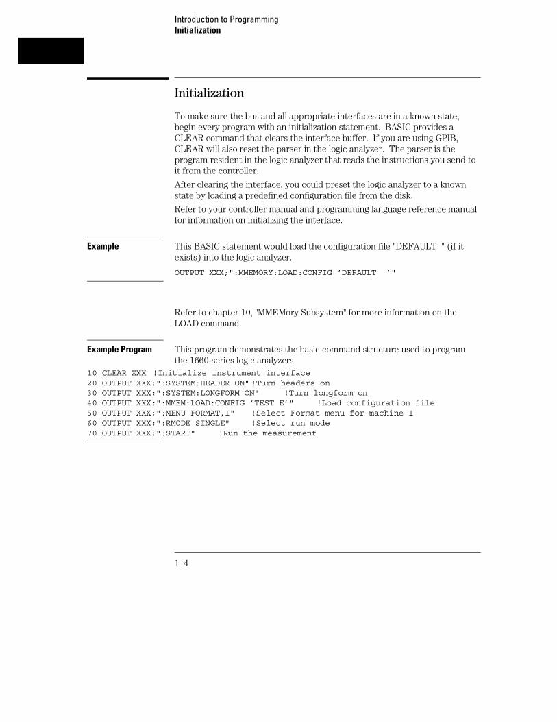
Initialization
To make sure the bus and all appropriate interfaces are in a known state,begin every program with an initialization statement. BASIC provides aCLEAR command that clears the interface buffer. If you are using GPIB,CLEAR will also reset the parser in the logic analyzer. The parser is theprogram resident in the logic analyzer that reads the instructions you send toit from the controller.
After clearing the interface, you could preset the logic analyzer to a knownstate by loading a predefined configuration file from the disk.
Refer to your controller manual and programming language reference manualfor information on initializing the interface.
Example This BASIC statement would load the configuration file "DEFAULT " (if itexists) into the logic analyzer.
OUTPUT XXX;":MMEMORY:LOAD:CONFIG ’DEFAULT ’"
Refer to chapter 10, "MMEMory Subsystem" for more information on theLOAD command.
Example Program This program demonstrates the basic command structure used to programthe 1660-series logic analyzers.
10 CLEAR XXX !Initialize instrument interface20 OUTPUT XXX;":SYSTEM:HEADER ON" !Turn headers on30 OUTPUT XXX;":SYSTEM:LONGFORM ON" !Turn longform on40 OUTPUT XXX;":MMEM:LOAD:CONFIG ’TEST E’" !Load configuration file50 OUTPUT XXX;":MENU FORMAT,1" !Select Format menu for machine 160 OUTPUT XXX;":RMODE SINGLE" !Select run mode70 OUTPUT XXX;":START" !Run the measurement
Introduction to ProgrammingInitialization
1–4

Instruction Syntax
To program the logic analyzer remotely, you must have an understanding ofthe command format and structure. The IEEE 488.2 standard governs syntaxrules pertaining to how individual elements, such as headers, separators,parameters and terminators, may be grouped together to form completeinstructions. Syntax definitions are also given to show how query responseswill be formatted. Figure 1-1 shows the three main syntactical parts of atypical program statement: Output Command, Device Address, andInstruction. The instruction is further broken down into three parts:Instruction header, White space, and Instruction parameters.
Figure 1-1
Program Message Syntax
Output Command
The output command depends on the language you choose to use.Throughout this guide, HP 9000 Series 200/300 BASIC 6.2 is used in theprogramming examples. If you use another language, you will need to findthe equivalents of Basic Commands, like OUTPUT, ENTER and CLEAR inorder to convert the examples. The instructions are always shown betweenthe double quotes.
Introduction to ProgrammingInstruction Syntax
1–5
Device Address
The location where the device address must be specified also depends on thehost language that you are using. In some languages, this could be specifiedoutside the output command. In BASIC, this is always specified after thekeyword OUTPUT. The examples in this manual use a generic address ofXXX. When writing programs, the number you use will depend on the cableyou use, in addition to the actual address. If you are using an GPIB, seechapter 2, "Programming over GPIB." If you are using RS-232C, seechapter 3, "Programming Over RS-232C."
Instructions
Instructions (both commands and queries) normally appear as a stringembedded in a statement of your host language, such as BASIC, Pascal or C.The only time a parameter is not meant to be expressed as a string is whenthe instruction’s syntax definition specifies block data. There are just a fewinstructions which use block data.
Instructions are composed of two main parts: the header, which specifies thecommand or query to be sent; and the parameters, which provide additionaldata needed to clarify the meaning of the instruction. Many queries do notuse any parameters.
Instruction Header
The instruction header is one or more keywords separated by colons (:). Thecommand tree in figure 4-1 illustrates how all the keywords can be joinedtogether to form a complete header (see chapter 4, "Programming andDocumentation Conventions").
The example in figure 1-1 shows a command. Queries are indicated byadding a question mark (?) to the end of the header. Many instructions canbe used as either commands or queries, depending on whether or not youhave included the question mark. The command and query forms of aninstruction usually have different parameters.
Introduction to ProgrammingDevice Address
1–6

When you look up a query in this programmer’s reference, you’ll find aparagraph labeled "Returned Format" under the one labeled "Query." Thesyntax definition by "Returned format" will always show the instructionheader in square brackets, like [:SYSTem:MENU], which means the textbetween the brackets is optional. It is also a quick way to see what theheader looks like.
White Space
White space is used to separate the instruction header from the instructionparameters. If the instruction does not use any parameters, white spacedoes not need to be included. White space is defined as one or more spaces.ASCII defines a space to be a character, represented by a byte, that has adecimal value of 32. Tabs can be used only if your controller first convertsthem to space characters before sending the string to the instrument.
Instruction Parameters
Instruction parameters are used to clarify the meaning of the command orquery. They provide necessary data, such as: whether a function should beon or off, which waveform is to be displayed, or which pattern is to be lookedfor. Each instruction’s syntax definition shows the parameters, as well as therange of acceptable values they accept. This chapter’s "Parameter DataTypes" section has all of the general rules about acceptable values.
When there is more than one parameter, they are separated by commas (,).White space surrounding the commas is optional.
Instruction Terminator
An instruction is executed after the instruction terminator is received. Theterminator is the NL (New Line) character. The NL character is an ASCIIlinefeed character (decimal 10).
The NL (New Line) terminator has the same function as an EOS (End OfString) and EOT (End Of Text) terminator.
Introduction to ProgrammingInstruction Terminator
1–7

Header Types
There are three types of headers: Simple Command, Compound Command,and Common Command.
Simple Command Header
Simple command headers contain a single keyword. START and STOP areexamples of simple command headers typically used in this logic analyzer.The syntax is: <function><terminator>
When parameters (indicated by <data>) must be included with the simplecommand header, the syntax is: <function><white_space><data><terminator>
Example :RMODE SINGLE<terminator>
Compound Command Header
Compound command headers are a combination of two or more programkeywords. The first keyword selects the subsystem, and the last keywordselects the function within that subsystem. Sometimes you may need to listmore than one subsystem before being allowed to specify the function. Thekeywords within the compound header are separated by colons. Forexample, to execute a single function within a subsystem, use the following::<subsystem>:<function><white_space><data><terminator>
Example :SYSTEM:LONGFORM ON
To traverse down one level of a subsystem to execute a subsystem withinthat subsystem, use the following:<subsystem>:<subsystem>:<function><white_space><data><terminator>
Example :MMEMORY:LOAD:CONFIG "FILE "
Introduction to ProgrammingHeader Types
1–8

Common Command Header
Common command headers control IEEE 488.2 functions within the logicanalyzer, such as, clear status. The syntax is: *<command header><terminator>
No white space or separator is allowed between the asterisk and thecommand header. *CLS is an example of a common command header.
Combined Commands in the Same Subsystem
To execute more than one function within the same subsystem, a semicolon(;) is used to separate the functions::<subsystem>:<function><whitespace><data>;<function><white space><data><terminator>
Example :SYSTEM:LONGFORM ON;HEADER ON
Duplicate Keywords
Identical function keywords can be used for more than one subsystem. Forexample, the function keyword MMODE may be used to specify the markermode in the subsystem for state listing or the timing waveforms:
• :SLIST:MMODE PATTERN - sets the marker mode to pattern inthe state listing.
• :TWAVEFORM:MMODE TIME - sets the marker mode to time in thetiming waveforms.
SLIST and TWAVEFORM are subsystem selectors, and they determine whichmarker mode is being modified.
Introduction to ProgrammingDuplicate Keywords
1–9

Query Usage
Logic analyzer instructions that are immediately followed by a question mark(?) are queries. After receiving a query, the logic analyzer parser places theresponse in the output buffer. The output message remains in the bufferuntil it is read or until another logic analyzer instruction is issued. Whenread, the message is transmitted across the bus to the designated listener(typically a controller).
Query commands are used to find out how the logic analyzer is currentlyconfigured. They are also used to get results of measurements made by thelogic analyzer.
Example This instruction places the current full-screen time for machine 1 in theoutput buffer.
:MACHINE1:TWAVEFORM:RANGE?
In order to prevent the loss of data in the output buffer, the output buffermust be read before the next program message is sent. Sending anothercommand before reading the result of the query will cause the output bufferto be cleared and the current response to be lost. This will also generate a"QUERY UNTERMINATED" error in the error queue. For example, when yousend the query :TWAVEFORM:RANGE? you must follow that with an inputstatement. In Basic, this is usually done with an ENTER statement.
In Basic, the input statement, ENTER XXX; Range, passes the value acrossthe bus to the controller and places it in the variable Range.
Additional details on how to use queries is in the next section of this chapter,"Receiving Information for the Instrument."
Introduction to ProgrammingQuery Usage
1–10

Program Header Options
Program headers can be sent using any combination of uppercase orlowercase ASCII characters. Logic analyzer responses, however, are alwaysreturned in uppercase.
Both program command and query headers may be sent in either long form(complete spelling), short form (abbreviated spelling), or any combination oflong form and short form.
Programs written in long form are easily read and are almost self-documenting. The short form syntax conserves the amount of controllermemory needed for program storage and reduces the amount of I/O activity.
The rules for short form syntax are discussed in chapter 4, "Programming andDocumentation Conventions."
Example Either of the following examples turns on the headers and long form.Long form:
OUTPUT XXX;":SYSTEM:HEADER ON;LONGFORM ON"
Short form:
OUTPUT XXX;":SYST:HEAD ON;LONG ON"
Introduction to ProgrammingProgram Header Options
1–11

Parameter Data Types
There are three main types of data which are used in parameters. They arenumeric, string, and keyword. A fourth type, block data, is used only for a fewinstructions: the DATA and SETup instructions in the SYSTem subsystem(see chapter 10); the CATalog, UPLoad, and DOWNload instructions in theMMEMory subsystem (see chapter 11). These syntax rules also show howdata may be formatted when sent back from the 1660-series logic analyzersas a response.
The parameter list always follows the instruction header and is separatedfrom it by white space. When more than one parameter is used, they areseparated by commas. You are allowed to include one or more white spacesaround the commas, but it is not mandatory.
Numeric data
For numeric data, you have the option of using exponential notation or usingsuffixes to indicate which unit is being used. However, exponential notationis only applicable to the decimal number base. Tables 5-1 and 5-2 in chapter5, "Message Communications and System Functions," list all availablesuffixes. Do not combine an exponent with a unit.
Example The following numbers are all equal:
28 = 0.28E2 = 280E-1 = 28000m = 0.028K.
The base of a number is shown with a prefix. The available bases are binary(#B), octal (#Q), hexadecimal (#H) and decimal (default).
Example The following numbers are all equal:
#B11100 = #Q34 = #H1C = 28
You may not specify a base in conjunction with either exponents or unitsuffixes. Additionally, negative numbers must be expressed in decimal.
Introduction to ProgrammingParameter Data Types
1–12

When a syntax definition specifies that a number is an integer, that meansthat the number should be whole. Any fractional part would be ignored,truncating the number. Numeric parameters that accept fractional values arecalled real numbers.
All numbers are expected to be strings of ASCII characters. Thus, whensending the number 9, you send a byte representing the ASCII code for thecharacter "9" (which is 57, or 0011 1001 in binary). A three-digit number,like 102, will take up three bytes (ASCII codes 49, 48 and 50). This is takencare of automatically when you include the entire instruction in a string.
String data
String data may be delimited with either single (’) or double (") quotes.String parameters representing labels are case-sensitive. For instance, thelabels "Bus A" and "bus a" are unique and should not be usedindiscriminately. Also pay attention to the presence of spaces, because theyact as legal characters just like any other. So, the labels "In" and " In" arealso two different labels.
Keyword data
In many cases a parameter must be a keyword. The available keywords arealways included with the instruction’s syntax definition. When sendingcommands, either the longform or shortform (if one exists) may be used.Uppercase and lowercase letters may be mixed freely. When receivingresponses, upper-case letters will be used exclusively. The use of longformor shortform in a response depends on the setting you last specified via theSYSTem:LONGform command (see chapter 10).
Introduction to ProgrammingParameter Data Types
1–13

Selecting Multiple Subsystems
You can send multiple program commands and program queries for differentsubsystems on the same line by separating each command with a semicolon.The colon following the semicolon enables you to enter a new subsystem.<instruction header><data>;:<instruction header><data><terminator>
Multiple commands may be any combination of simple, compound andcommon commands.
Example :MACHINE1:ASSIGN2;:SYSTEM:HEADERS ON
Introduction to ProgrammingSelecting Multiple Subsystems
1–14

Receiving Information from the Instrument
After receiving a query (logic analyzer instruction followed by a questionmark), the logic analyzer interrogates the requested function and places theanswer in its output queue. The answer remains in the output queue until itis read, or, until another command is issued. When read, the message istransmitted across the bus to the designated listener (typically a controller).The input statement for receiving a response message from an logicanalyzer’s output queue usually has two parameters: the device address anda format specification for handling the response message.
All results for queries sent in a program message must be read before anotherprogram message is sent. For example, when you send the query:MACHINE1:ASSIGN?, you must follow that query with an input statement.In Basic, this is usually done with an ENTER statement.
The format for handling the response messages is dependent on both thecontroller and the programming language.
Example To read the result of the query command :SYSTEM:LONGFORM? you canexecute this Basic statement to enter the current setting for the long formcommand in the numeric variable Setting.
ENTER XXX; Setting
1–15

Response Header Options
The format of the returned ASCII string depends on the current settings ofthe SYSTEM HEADER and LONGFORM commands. The general format is<instruction_header><space><data><terminator>
The header identifies the data that follows (the parameters) and is controlledby issuing a :SYSTEM:HEADER ON/OFF command. If the state of theheader command is OFF, only the data is returned by the query.
The format of the header is controlled by the :SYSTEM:LONGFORM ON/OFFcommand. If long form is OFF , the header will be in its short form and theheader will vary in length, depending on the particular query. The separatorbetween the header and the data always consists of one space.
A command or query may be sent in either long form or short form, or in anycombination of long form and short form. The HEADER and LONGFORMcommands only control the format of the returned data, and, they have noaffect on the way commands are sent.
Refer to chapter 10, "SYSTem Subsystem" for information on turning theHEADER and LONGFORM commands on and off.
Examples The following examples show some possible responses for a:MACHINE1:SFORMAT:THRESHOLD2? query:
with HEADER OFF:
<data><terminator>
with HEADER ON and LONGFORM OFF:
:MACH1:SFOR:THR2 <white_space><data><terminator>
with HEADER ON and LONGFORM ON:
:MACHINE1:SFORMAT:THRESHOLD2 <white_space><data><terminator>
Introduction to ProgrammingResponse Header Options
1–16

Response Data Formats
Both numbers and strings are returned as a series of ASCII characters, asdescribed in the following sections. Keywords in the data are returned in thesame format as the header, as specified by the LONGform command. Likethe headers, the keywords will always be in uppercase.
Examples The following are possible responses to the MACHINE1: TFORMAT: LAB?’ADDR’ query.
Header on; Longform on
MACHINE1:TFORMAT:LABEL "ADDR ",19,POSITIVE<terminator>
Header on;Longform off
MACH1:TFOR:LAB "ADDR ",19,POS<terminator>
Header off; Longform on
"ADDR ",19,POSITIVE<terminator>
Header off; Longform off
"ADDR ",19,POS<terminator>
Refer to the individual commands in Parts 2 through 4 of this guide forinformation on the format (alpha or numeric) of the data returned from eachquery.
Introduction to ProgrammingResponse Data Formats
1–17

String Variables
Because there are so many ways to code numbers, the 1660-series logicanalyzers handle almost all data as ASCII strings. Depending on your hostlanguage, you may be able to use other types when reading in responses.
Sometimes it is helpful to use string variables in place of constants to sendinstructions to the 1660-series logic analyzers, such as, including the headerswith a query response.
Example This example combines variables and constants in order to make it easier toswitch from MACHINE1 to MACHINE2. In BASIC, the & operator is used forstring concatenation.
5 OUTPUT XXX;":SELECT 1" !Select the logic analyzer10 LET Machine$ = ":MACHINE2" !Send all instructions to machine 220 OUTPUT XXX; Machine$ & ":TYPE STATE" !Make machine a state analyzer30 ! Assign all labels to be positive40 OUTPUT XXX; Machine$ & ":SFORMAT:LABEL ’CHAN 1’, POS"50 OUTPUT XXX; Machine$ & ":SFORMAT:LABEL ’CHAN 2’, POS"60 OUTPUT XXX; Machine$ & ":SFORMAT:LABEL ’OUT’, POS"99 END
If you want to observe the headers for queries, you must bring the returneddata into a string variable. Reading queries into string variables requires littleattention to formatting.
Example This command line places the output of the query in the string variableResult$.
ENTER XXX;Result$
In the language used for this book (HP BASIC 6.2), string variables are case-sensitive and must be expressed exactly the same each time they are used.
The output of the logic analyzer may be numeric or character data dependingon what is queried. Refer to the specific commands, in Part 2 of this guide,for the formats and types of data returned from queries.
Introduction to ProgrammingString Variables
1–18

Example The following example shows logic analyzer data being returned to a stringvariable with headers off:10 OUTPUT XXX;":SYSTEM:HEADER OFF"20 DIM Rang$[30]30 OUTPUT XXX;":MACHINE1:TWAVEFORM:RANGE?"40 ENTER XXX;Rang$50 PRINT Rang$60 END
After running this program, the controller displays: +1.00000E-05
Numeric Base
Most numeric data will be returned in the same base as shown onscreen.When the prefix #B precedes the returned data, the value is in the binarybase. Likewise, #Q is the octal base and #H is the hexadecimal base. If noprefix precedes the returned numeric data, then the value is in the decimalbase.
Numeric Variables
If your host language can convert from ASCII to a numeric format, then youcan use numeric variables. Turning off the response headers will help youavoid accidently trying to convert the header into a number.
Example The following example shows logic analyzer data being returned to a numericvariable.10 OUTPUT XXX;":SYSTEM:HEADER OFF"20 OUTPUT XXX;":MACHINE1:TWAVEFORM:RANGE?"30 ENTER XXX;Rang40 PRINT Rang50 END
Introduction to ProgrammingNumeric Base
1–19

This time the format of the number (such as, whether or not exponentialnotation is used) is dependant upon your host language. In Basic, the outputwill look like: 1.E-5
Definite-Length Block Response Data
Definite-length block response data, also refered to as block data, allows anytype of device-dependent data to be transmitted over the system interface asa series of data bytes. Definite-length blick data is particularly useful forsending large quantities of data, or, for sending 8-bit extended ASCII codes.The syntax is a pound sign ( # ) followed by a non-zero digit representing thenumber of digits in the decimal integer. Following the non zero digit is thedecimal integer that states the number of 8-bit data bytes to follow. Thisnumber is followed by the actual data.
Indefinite-length block data is not supported on the 1660-series logicanalyzers.
For example, for transmitting 80 bytes of data, the syntax would be:
Figure 1-2
Definite-length Block Response Data
The "8" states the number of digits that follow, and "00000080" states thenumber of bytes to be transmitted, which is 80.
Introduction to ProgrammingDefinite-Length Block Response Data
1–20

Multiple Queries
You can send multiple queries to the logic analyzer within a single programmessage, but you must also read them back within a single program message.This can be accomplished by either reading them back into a string variableor into multiple numeric variables.
Example You can read the result of the query :SYSTEM:HEADER?;LONGFORM? intothe string variable Results$ with the command:
ENTER XXX; Results$
When you read the result of multiple queries into string variables, eachresponse is separated by a semicolon.
Example The response of the query :SYSTEM:HEADER?:LONGFORM? with HEADERand LONGFORM turned on is:
:SYSTEM:HEADER 1;:SYSTEM:LONGFORM 1
If you do not need to see the headers when the numeric values are returned,then you could use numeric variables. When you are receiving numeric datainto numeric variables, the headers should be turned off. Otherwise theheaders may cause misinterpretation of returned data.
Example The following program message is used to read the query:SYSTEM:HEADERS?;LONGFORM? into multiple numeric variables:
ENTER XXX; Result1, Result2
Introduction to ProgrammingMultiple Queries
1–21

Instrument Status
Status registers track the current status of the logic analyzer. By checkingthe instrument status, you can find out whether an operation has beencompleted, whether the instrument is receiving triggers, and more.Chapter 6, "Status Reporting," explains how to check the status of theinstrument.
Introduction to ProgrammingInstrument Status
1–22

2
Programming Over GPIB

Introduction
This section describes the interface functions and some generalconcepts of the GPIB. In general, these functions are defined by IEEE488.1 (GPIB bus standard). They deal with general bus managementissues, as well as messages which can be sent over the bus as buscommands.
2–2
Interface Capabilities
The interface capabilities of the 1660-series logic analyzers, as defined byIEEE 488.1 are SH1, AH1, T5, TE0, L3, LE0, SR1, RL1, PP0, DC1, DT1, C0,and E2.
Command and Data Concepts
The GPIB has two modes of operation: command mode and data mode. Thebus is in command mode when the ATN line is true. The command mode isused to send talk and listen addresses and various bus commands, such as agroup execute trigger (GET). The bus is in the data mode when the ATN lineis false. The data mode is used to convey device-dependent messages acrossthe bus. These device-dependent messages include all of the instrumentcommands and responses found in chapters 8 through 35 of this manual.
Addressing
By using the front-panel I/O and SELECT keys, the GPIB interface can beplaced in either talk only mode, "Printer connected to GPIB," or in addressedtalk/listen mode, "Controller connected to GPIB," (see chapter 16, "TheRS-232/GPIB Menu" in the Agilent Technologies 1660-Series Logic
Analyzer User’s Reference). Talk only mode must be used when you wantthe logic analyzer to talk directly to a printer without the aid of a controller.Addressed talk/listen mode is used when the logic analyzer will operate inconjunction with a controller. When the logic analyzer is in the addressedtalk/listen mode, the following is true:
• Each device on the GPIB resides at a particular address ranging from 0 to30.
• The active controller specifies which devices will talk and which will listen.
• An instrument, therefore, may be talk-addressed, listen-addressed, orunaddressed by the controller.
Programming Over GPIBInterface Capabilities
2–3

If the controller addresses the instrument to talk, it will remain configured totalk until it receives:
• an interface clear message (IFC)
• another instrument’s talk address (OTA)
• its own listen address (MLA)
• a universal untalk (UNT) command.
If the controller addresses the instrument to listen, it will remain configuredto listen until it receives:
• an interface clear message (IFC)
• its own talk address (MTA)
• a universal unlisten (UNL) command.
Communicating Over the GPIB Bus (HP 9000 Series200/300 Controller)
Because GPIB can address multiple devices through the same interface card,the device address passed with the program message must include not onlythe correct instrument address, but also the correct interface code.
Interface Select Code (Selects the Interface)
Each interface card has its own interface select code. This code is used bythe controller to direct commands and communications to the properinterface. The default is always "7" for GPIB controllers.
Instrument Address (Selects the Instrument)
Each instrument on the GPIB port must have a unique instrument addressbetween decimals 0 and 30. The device address passed with the programmessage must include not only the correct instrument address, but also thecorrect interface select code.
Programming Over GPIBCommunicating Over the GPIB Bus (HP 9000 Series 200/300 Controller)
2–4
Example For example, if the instrument address is 4 and the interface select code is 7,the instruction will cause an action in the instrument at device address 704.DEVICE ADDRESS = (Interface Select Code) X 100 + (InstrumentAddress)
Local, Remote, and Local Lockout
The local, remote, and remote with local lockout modes may be used forvarious degrees of front-panel control while a program is running. The logicanalyzer will accept and execute bus commands while in local mode, and thefront panel will also be entirely active. If the 1660-series logic analyzer is inremote mode, the logic analyzer will go from remote to local with any frontpanel activity. In remote with local lockout mode, all controls (except thepower switch) are entirely locked out. Local control can only be restored bythe controller.
Hint Cycling the power will also restore local control, but this will also resetcertain GPIB states. It also resets the logic analyzer to the power-on defaultsand purges any acquired data in the acquisition memory.
The instrument is placed in remote mode by setting the REN (RemoteEnable) bus control line true, and then addressing the instrument to listen.The instrument can be placed in local lockout mode by sending the locallockout (LLO) command (see SYSTem:LOCKout in chapter 9, "MainframeCommands"). The instrument can be returned to local mode by eithersetting the REN line false, or sending the instrument the go to local (GTL)command.
Programming Over GPIBLocal, Remote, and Local Lockout
2–5

Bus Commands
The following commands are IEEE 488.1 bus commands (ATN true). IEEE488.2 defines many of the actions which are taken when these commands arereceived by the logic analyzer.
Device Clear
The device clear (DCL) or selected device clear (SDC) commands clear theinput and output buffers, reset the parser, clear any pending commands, andclear the Request-OPC flag.
Group Execute Trigger (GET)
The group execute trigger command will cause the same action as theSTART command for Group Run: the instrument will acquire data for theactive waveform and listing displays.
Interface Clear (IFC)
This command halts all bus activity. This includes unaddressing all listenersand the talker, disabling serial poll on all devices, and returning control to thesystem controller.
Programming Over GPIBBus Commands
2–6

3
Programming Over RS-232C

Introduction
This chapter describes the interface functions and some generalconcepts of the RS-232C. The RS-232C interface on this instrument isAgilent Technologies’ implementation of EIA Recommended StandardRS-232C, "Interface Between Data Terminal Equipment and Data
Communications Equipment Employing Serial Binary Data
Interchange." With this interface, data is sent one bit at a time, andcharacters are not synchronized with preceding or subsequent datacharacters. Each character is sent as a complete entity withoutrelationship to other events.
3–2
Interface Operation
The 1660-series logic analyzers can be programmed with a controller overRS-232C using either a minimum three-wire or extended hardwire interface.The operation and exact connections for these interfaces are described inmore detail in the following sections. When you are programming a1660-series logic analyzer over RS-232C with a controller, you are normallyoperating directly between two DTE (Data Terminal Equipment) devices ascompared to operating between a DTE device and a DCE (DataCommunications Equipment) device.
When operating directly between two DTE devices, certain considerationsmust be taken into account. For a three-wire operation, XON/XOFF must beused to handle protocol between the devices. For extended hardwireoperation, protocol may be handled either with XON/XOFF or bymanipulating the CTS and RTS lines of the RS-232C link. For both three-wire and extended hardwire operation, the DCD and DSR inputs to the logicanalyzer must remain high for proper operation.
With extended hardwire operation, a high on the CTS input allows the logicanalyzer to send data, and a low disables the logic analyzer data transmission.Likewise, a high on the RTS line allows the controller to send data, and a lowsignals a request for the controller to disable data transmission. Becausethree-wire operation has no control over the CTS input, internal pull-upresistors in the logic analyzer assure that this line remains high for properthree-wire operation.
RS-232C Cables
Selecting a cable for the RS-232C interface depends on your specificapplication, and, whether you wish to use software or hardware handshakeprotocol. The following paragraphs describe which lines of the 1660-serieslogic analyzer are used to control the handshake operation of the RS-232Crelative to the system. To locate the proper cable for your application, referto the reference manual for your computer or controller. Your computer orcontroller manual should describe the exact handshake protocol yourcontroller can use to operate over the RS-232C bus. Also in this chapter youwill find cable recommendations for hardware handshake.
Programming Over RS-232CInterface Operation
3–3

Minimum Three-Wire Interface with Software Protocol
With a three-wire interface, the software (as compared to interfacehardware) controls the data flow between the logic analyzer and thecontroller. The three-wire interface provides no hardware means to controldata flow between the controller and the logic analyzer. Therefore,XON/OFF protocol is the only means to control this data flow. Thethree-wire interface provides a much simpler connection between devicessince you can ignore hardware handshake requirements.
The communications software you are using in your computer/controller mustbe capable of using XON/XOFF exclusively in order to use three-wire interfacecables. For example, some communications software packages can useXON/XOFF but are also dependent on the CTS, and DSR lines being true tocommunicate.
The logic analyzer uses the following connections on its RS-232C interface forthree-wire communication:
• Pin 7 SGND (Signal Ground)
• Pin 2 TD (Transmit Data from logic analyzer)
• Pin 3 RD (Receive Data into logic analyzer)
The TD (Transmit Data) line from the logic analyzer must connect to the RD(Receive Data) line on the controller. Likewise, the RD line from the logicanalyzer must connect to the TD line on the controller. Internal pull-upresistors in the logic analyzer assure the DCD, DSR, and CTS lines remainhigh when you are using a three-wire interface.
Extended Interface with Hardware Handshake
With the extended interface, both the software and the hardware can controlthe data flow between the logic analyzer and the controller. This allows youto have more control of data flow between devices. The logic analyzer usesthe following connections on its RS-232C interface for extended interfacecommunication:
Programming Over RS-232CMinimum Three-Wire Interface with Software Protocol
3–4

• Pin 7 SGND (Signal Ground)
• Pin 2 TD (Transmit Data from logic analyzer)
• Pin 3 RD (Receive Data into logic analyzer)
The additional lines you use depends on your controller’s implementation ofthe extended hardwire interface.
• Pin 4 RTS (Request To Send) is an output from the logic analyzer whichcan be used to control incoming data flow.
• Pin 5 CTS (Clear To Send) is an input to the logic analyzer whichcontrols data flow from the logic analyzer.
• Pin 6 DSR (Data Set Ready) is an input to the logic analyzer whichcontrols data flow from the logic analyzer within two bytes.
• Pin 8 DCD (Data Carrier Detect) is an input to the logic analyzer whichcontrols data flow from the logic analyzer within two bytes.
• Pin 20 DTR (Data Terminal Ready) is an output from the logic analyzerwhich is enabled as long as the logic analyzer is turned on.
The TD (Transmit Data) line from the logic analyzer must connect to the RD(Receive Data) line on the controller. Likewise, the RD line from the logicanalyzer must connect to the TD line on the controller.
The RTS (Request To Send), is an output from the logic analyzer which canbe used to control incoming data flow. A true on the RTS line allows thecontroller to send data and a false signals a request for the controller todisable data transmission.
The CTS (Clear To Send), DSR (Data Set Ready), and DCD (Data CarrierDetect) lines are inputs to the logic analyzer, which control data flow fromthe logic analyzer. Internal pull-up resistors in the logic analyzer assure theDCD and DSR lines remain high when they are not connected. If DCD orDSR are connected to the controller, the controller must keep these linesalong with the CTS line high to enable the logic analyzer to send data to thecontroller. A low on any one of these lines will disable the logic analyzer datatransmission. Pulling the CTS line low during data transmission will stoplogic analyzer data transmission immediately. Pulling either the DSR or DCDline low during data transmission will stop logic analyzer data transmission,but as many as two additional bytes may be transmitted from the logicanalyzer.
Programming Over RS-232CExtended Interface with Hardware Handshake
3–5
Cable Examples
HP 9000 Series 300
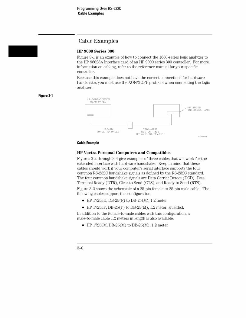
Figure 3-1 is an example of how to connect the 1660-series logic analyzer tothe HP 98628A Interface card of an HP 9000 series 300 controller. For moreinformation on cabling, refer to the reference manual for your specificcontroller.
Because this example does not have the correct connections for hardwarehandshake, you must use the XON/XOFF protocol when connecting the logicanalyzer.
Figure 3-1
Cable Example
HP Vectra Personal Computers and Compatibles
Figures 3-2 through 3-4 give examples of three cables that will work for theextended interface with hardware handshake. Keep in mind that thesecables should work if your computer’s serial interface supports the fourcommon RS-232C handshake signals as defined by the RS-232C standard.The four common handshake signals are Data Carrier Detect (DCD), DataTerminal Ready (DTR), Clear to Send (CTS), and Ready to Send (RTS).
Figure 3-2 shows the schematic of a 25-pin female to 25-pin male cable. Thefollowing cables support this configuration:
• HP 17255D, DB-25(F) to DB-25(M), 1.2 meter
• HP 17255F, DB-25(F) to DB-25(M), 1.2 meter, shielded.
In addition to the female-to-male cables with this configuration, amale-to-male cable 1.2 meters in length is also available:
• HP 17255M, DB-25(M) to DB-25(M), 1.2 meter
Programming Over RS-232C Cable Examples
3–6

Figure 3-2
25-pin (F) to 25-pin (M) Cable
Figure 3-3 shows the schematic of a 25-pin male to 25-pin male cable 5meters in length. The following cable supports this configuration:
• HP 13242G, DB-25(M) to DB-25(M), 5 meter
Figure 3-3
25-pin (M) to 25-pin (M) Cable
Programming Over RS-232C Cable Examples
3–7

Figure 3-4 shows the schematic of a 9-pin female to 25-pin male cable. Thefollowing cables support this configuration:
• HP 24542G, DB-9(F) to DB-25(M), 3 meter
• HP 24542H, DB-9(F) to DB-25(M), 3 meter, shielded
• HP 45911-60009, DB-9(F) to DB-25(M), 1.5 meter
Figure 3-4
9-pin (F) to 25-pin (M) Cable
Configuring the Logic Analzer Interface
The RS-232C menu field in the System Configuration Menu allows you accessto the RS-232C Configuration menu where the RS-232C interface isconfigured. If you are not familiar with how to configure the RS-232Cinterface, refer to the Agilent Technologies 1660-Series Logic Analyzer
User’s Reference.
Programming Over RS-232CConfiguring the Logic Analzer Interface
3–8

Interface Capabilities
The baud rate, stopbits, parity, protocol, and databits must be configuredexactly the same for both the controller and the logic analyzer to properlycommunicate over the RS-232C bus. The RS-232C interface capabilities ofthe 1660-series logic analyzers are listed below:
• Baud Rate: 110, 300, 600, 1200, 2400, 4800, 9600, or 19.2k
• Stop Bits: 1, 1.5, or 2
• Parity: None, Odd, or Even
• Protocol: None or XON/XOFF
• Data Bits: 8
Protocol
NONE With a three-wire interface, selecting NONE for the protocoldoes not allow the sending or receiving device to control dataflow. Nocontrol over the data flow increases the possibility of missing data ortransferring incomplete data.
With an extended hardwire interface, selecting NONE allows a hardwarehandshake to occur. With hardware handshake, the hardware signals controldataflow.
XON/XOFF XON/XOFF stands for Transmit On/Transmit Off. With thismode, the receiver (controller or logic analyzer) controls dataflow, and,can request that the sender (logic analyzer or controller) stop dataflow.By sending XOFF (ASCII 19) over its transmit data line, the receiverrequests that the sender disables data transmission. A subsequent XON(ASCII 17) allows the sending device to resume data transmission.
Data Bits
Data bits are the number of bits sent and received per character thatrepresent the binary code of that character. Characters consist of either 7 or8 bits, depending on the application. The 1660-series logic analyzer supports8 bit only.
8 Bit Mode Information is usually stored in bytes (8 bits at a time).With 8-bit mode, you can send and receive data just as it is stored,without the need to convert the data.
Programming Over RS-232CInterface Capabilities
3–9

The controller and the 1660-series logic analyzer must be in the same bitmode to properly communicate over the RS-232C. This means that thecontroller must have the capability to send and receive 8 bit data.
See Also For more information on the RS-232C interface, refer to the Agilent
Technologies 1660-Series Logic Analyzer User’s Reference. Forinformation on RS-232C voltage levels and connector pinouts, refer to theAgilent Technologies 1660-Series Logic Analyzer Service Guide.
RS-232C Bus Addressing
The RS-232C address you must use is dependent on the computer orcontroller you are using to communicate with the logic analyzer.
HP Vectra Personal Computers or compatibles
If you are using an HP Vectra Personal Computer or compatible, it must havean unused serial port to which you connect the logic analyzer’s RS-232C port.The proper address for the serial port is dependent on the hardwareconfiguration of your computer. Additionally, your communications softwaremust be configured to address the proper serial port. Refer to your computerand communications software manuals for more information on setting upyour serial port address.
HP 9000 Series 300 Controllers
Each RS-232C interface card for the HP 9000 Series 300 Controller has itsown interface select code. This code is used by the controller for directingcommands and communications to the proper interface by specifying thecorrect interface code for the device address.
Generally, the interface select code can be any decimal value between 0 and31, except for those interface codes which are reserved by the controller forinternal peripherals and other internal interfaces. This value can be selectedthrough switches on the interface card. For example, if your RS-232Cinterface select code is 9, the device address required to communicate overthe RS-232C bus is 9. For more information, refer to the reference manualfor your interface card or controller.
Programming Over RS-232CRS-232C Bus Addressing
3–10

Lockout Command
To lockout the front-panel controls, use the SYSTem command LOCKout.When this function is on, all controls (except the power switch) are entirelylocked out. Local control can only be restored by sending the :LOCKout OFFcommand.
Hint Cycling the power will also restore local control, but this will also resetcertain RS-232C states. It also resets the logic analyzer to the power-ondefaults and purges any acquired data in the acquisition memory of all theinstalled modules.
See Also For more information on this command see chapter 10, "System Commands."
Programming Over RS-232CLockout Command
3–11

3–12

4
Programming andDocumentation Conventions

Introduction
This chapter covers the programming conventions used inprogramming the instrument, as well as the documentationconventions used in this manual. This chapter also contains a detaileddescription of the command tree and command tree traversal.
4–2

Truncation Rule
The truncation rule for the keywords used in headers and parameters is:
• If the longform has four or fewer characters, there is no change in theshortform. When the longform has more than four characters theshortform is just the first four characters, unless the fourth character isa vowel. In that case only the first three characters are used.
There are some commands that do not conform to the truncation rule by design.These will be noted in their respective description pages.
Some examples of how the truncation rule is applied to various commandsare shown in table 4-1.
Table 4-1 Truncation Examples
Long Form Short Form
OFF OFF
DATA DATA
START STAR
LONGFORM LONG
DELAY DEL
ACCUMULATE ACC
Programming and Documentation ConventionsTruncation Rule
4–3

Infinity Representation
The representation of infinity is 9.9E+37 for real numbers and 32767 forintegers. This is also the value returned when a measurement cannot bemade.
Sequential and Overlapped Commands
IEEE 488.2 makes the distinction between sequential and overlappedcommands. Sequential commands finish their task before the execution ofthe next command starts. Overlapped commands run concurrently; therefore,the command following an overlapped command may be started before theoverlapped command is completed. The overlapped commands for the1660-series logic analyzers are STARt and STOP.
Response Generation
IEEE 488.2 defines two times at which query responses may be buffered.The first is when the query is parsed by the instrument and the second iswhen the controller addresses the instrument to talk so that it may read theresponse. The 1660-series logic analyzers will buffer responses to a querywhen it is parsed.
Syntax Diagrams
At the beginning of each chapter in Parts 2 through 4, "Commands," is asyntax diagram showing the proper syntax for each command. All characterscontained in a circle or oblong are literals, and must be entered exactly asshown. Words and phrases contained in rectangles are names of items usedwith the command and are described in the accompanying text of eachcommand. Each line can only be entered from one direction as indicated bythe arrow on the entry line. Any combination of commands and argumentsthat can be generated by following the lines in the proper direction issyntactically correct. An argument is optional if there is a path around it.When there is a rectangle which contains the word "space," a white spacecharacter must be entered. White space is optional in many other places.
Programming and Documentation ConventionsInfinity Representation
4–4

Notation Conventions and Definitions
The following conventions are used in this manual when describingprogramming rules and example.
< > Angular brackets enclose words or characters that are used to symbolize aprogram code parameter or a bus command
::= "is defined as." For example, A ::= B indicates that A can be replaced by B inany statement containing A.
| "or." Indicates a choice of one element from a list. For example, A | Bindicates A or B, but not both.
... An ellipsis (trailing dots) is used to indicate that the preceding element maybe repeated one or more times.
[ ] Square brackets indicate that the enclosed items are optional.
{ } When several items are enclosed by braces and separated by vertical bars (|),one, and only one of these elements must be selected.
XXX Three Xs after an ENTER or OUTPUT statement represent the deviceaddress required by your controller.
<NL> Linefeed (ASCII decimal 10).
The Command Tree
The command tree (figure 4-1) shows all commands in the 1660-series logicanalyzers and the relationship of the commands to each other. Parametersare not shown in this figure. The command tree allows you to see what the1660-series logig analyzer parser expects to receive. All legal headers can becreated by traversing down the tree, adding keywords until the end of abranch has been reached.
Programming and Documentation ConventionsNotation Conventions and Definitions
4–5

Command Types
As shown in chapter 1, "Header Types," there are three types of headers.Each header has a corresponding command type. This section shows howthey relate to the command tree.
System Commands The system commands reside at the top level ofthe command tree. These commands are always parsable if they occur atthe beginning of a program message, or are preceded by a colon. STARTand STOP are examples of system commands.
Subsystem Commands Subsystem commands are grouped togetherunder a common node of the tree, such as the MMEMORY commands.
Common Commands Common commands are independent of the tree,and do not affect the position of the parser within the tree. *CLS and*RST are examples of common commands.
Tree Traversal Rules
Command headers are created by traversing down the command tree. Foreach group of keywords not separated by a branch, one keyword must beselected. As shown on the tree, branches are always preceded by colons. Donot add spaces around the colons. The following two rules apply to traversingthe tree:
A leading colon (the first character of a header) or a <terminator> places theparser at the root of the command tree.
Executing a subsystem command places you in that subsystem until a leadingcolon or a <terminator> is found. The parser will stay at the colon above thekeyword where the last header terminated. Any command below that pointcan be sent within the current program message without sending thekeywords(s) which appear above them.
Programming and Documentation ConventionsTree Traversal Rules
4–6

The following examples are written using HP BASIC 6.2 on a HP 9000 Series200/300 Controller. The quoted string is placed on the bus, followed by acarriage return and linefeed (CRLF). The three Xs (XXX) shown in thismanual after an ENTER or OUTPUT statement represents the device addressrequired by your controller.
Example 1 In this example, the colon between SYSTEM and HEADER is necessary sinceSYSTEM:HEADER is a compound command. The semicolon between theHEADER command and the LONGFORM command is the required <programmessage unit separator> . The LONGFORM command does not needSYSTEM preceding it, since the SYSTEM:HEADER command sets the parserto the SYSTEM node in the tree.
OUTPUT XXX;":SYSTEM:HEADER ON;LONGFORM ON"
Example 2 In the first line of this example, the subsystem selector is implied for theSTORE command in the compound command. The STORE command mustbe in the same program message as the INITIALIZE command, since the<program message terminator> will place the parser back at the rootof the command tree.
A second way to send these commands is by placing MMEMORY: before theSTORE command as shown in the fourth line of this example 2.
OUTPUT XXX;":MMEMORY:INITIALIZE;STORE ’FILE ’,’FILEDESCRIPTION’"
or
OUTPUT XXX;":MMEMORY:INITIALIZE"OUTPUT XXX;":MMEMORY:STORE ’FILE ’,’FILE DESCRIPTION’"
Example 3 In this example, the leading colon before SYSTEM tells the parser to go backto the root of the command tree. The parser can then see theSYSTEM:PRINT command.
OUTPUT XXX;":MMEM:CATALOG?;:SYSTEM:PRINT ALL"
Programming and Documentation ConventionsTree Traversal Rules
4–7

Figure 4-1
1660-Series Logic Analyzer Command Tree
Programming and Documentation ConventionsTree Traversal Rules
4–8

Figure 4-1 (continued)
1660-Series Logic Analyzer Command Tree (continued)
Programming and Documentation ConventionsTree Traversal Rules
4–9

Figure 4-1 (continued)
1660-Series Logic Analyzer Command Tree (continued)
Programming and Documentation ConventionsTree Traversal Rules
4–10

Table 4-2
Alphabetic Command Cross-Reference
Command SubsystemABVOLt MARKerACCumulate SCHart, SWAVeform, TWAVeform,
DISPlayACQMode TFORmatACQuisition STRigger, SWAVeform, TTRigger,
TWAVeformALL MEASureARM MACHineASSign MACHineAUToload MMEMoryAUToscale MODULE LEVELAVOLt MARKerBASE SYMBolBEEPer MainframeBRANch STRigger, TTRiggerBVOLt MARKerCAPability MainframeCARDcage MainframeCATalog MMEMoryCENTer SWAVeform, TWAVeform, MARKerCESE MainframeCESR MainframeCLEar COMPare, STRigger, TTRiggerCLOCk SFORmatCLRPattern SLISt, SWAVeform, TLISt, TWAVeformCLRStat SWAVeform, TWAVeformCMASk COMPareCOLumn SLISt, TLIStCONDition TRIGgerCONNect DISPlayCOPY COMPare, MMEMoryCOUNt ACQuire, WAVeformlCOUPling CHANNelDATA COMPare, SLISt, SYSTem, TLISt,
WAVeformDELay SWAVeform, TWAVeform, WLISt,
TIMebase. TRIGgerDELete INTermoduleDIGitize ROOTDOWNload MMEMory
Command SubsystemDSP SYSTemECL CHANnelEOI MainframeERRor SYSTemFALLtime MEASureFIND COMPare, STRigger, TTRiggerFORMat WAVeformFREQuency MEASureGLEDge TTRiggerHAXis SCHartHEADer SYSTemHTIMe INTermoduleMOPQual SFORmatMQUal SFORmatMSI MMEMoryNAMEMACHineOCONdition TLISt, TWAVeformOPATtern SLISt, TLISt, TWAVeformOSEarch SLISt, TLISt, TWAVeformOSTate SLISt, TLISt, WLIStOTAGSLISt, TLIStOTIMe TWAVeform, WLIStOVERlay SLIStPACKMMEMoryPATTern SYMBolPRINt SYSTemPURGe MMEMoryRANGe COMPare, STRigger, SWAVeform,
SYMBol, TTRigger, TWAVeform, WLIStREMove SFORmat, SLISt, SWAVeform, SYMBol,
TFORmat, TLISt, TWAVeform, WLIStREName MACHineREName MMEMoryRESource MACHineRMODe MainframeRTC Mainframe
Programming and Documentation ConventionsTree Traversal Rules
4–11

Table 4-2 (continued)
Alphabetic Command Cross-Reference (continued)
Command SubsystemINITialize MMEMoryINPort INTermoduleINSert INTermodule, SWAVeform, TWAVeform,
WLISt, DISPlayLABel SFORmat, TFORmat, DISPlayLER MainframeLEVel TRIGgerLEVelarm MACHineLINE COMPare, SLISt, TLISt, WLIStLOAD MMEMoryLOCKout MainframeLOGic TRIGgerLONGform SYSTemMASTer SFORmatMENU COMPare, MainframeMESE MainframeMESR MainframeMINus DISPlayMMODe SLISt, TLISt, TWAVeformMODE SFORmat, TIMebase, TRIGgerMOPQual SFORmatMQUal SFORmatMSI MMEMoryMSTats MARKerNAME MACHineNWIDth MEASureOAUTo MARKerOCONdition TLISt, TWAVeformOFFSet CHANnelOPATtern SLISt, TLISt, TWAVeformOSEarch SLISt, TLISt, TWAVeformOSTate SLISt, TLISt, WLIStOTAG SLISt, TLIStOTIMe TWAVeform, WLISt, MARKerOVERlay SLISt, DISPlayOVERshoot MEASurePACK MMEMoryPATH TRIGgerPERiod MEASurePATTern SYMBol
Command SubsystemPLUS DISPlayPOINts WAVeformPRINt SYSTemPREamble WAVeformPREShoot MEASurePROBe CHANnelPURGe MMEMoryPWIDth MEASureRANGe COMPare, STRigger, SWAVeform,
SYMBol, TTRigger, TWAVeform, WLISt,CHANnel, TIMebase
RECord WAVeformTREE INTermoduleTTIMe INTermoduleTYPE MACHineUPLoad MMEMoryVAXis SCHartVOLume MMEMoryVRUNs SLISt, TLISt, TWAVeformWIDTh SYMBolXCONdition TLISt, TWAVeformXOTag SLISt, TLIStXOTime SLISt, TLISt, TWAVeform, WLIStXPATtern SLISt, TLISt, TWAVeformXSEarch SLISt, TLISt, TWAVeformXSTate SLISt, TLISt, WLIStXTAG SLISt, TLIStXTIMe TWAVeform, WLISt
Programming and Documentation ConventionsTree Traversal Rules
4–12

Table 4-2 (continued)
Alphabetic Command Cross-Reference (continued)
Command SubsystemREMove SFORmat, SLISt, SWAVeform, SYMBol,
TFORmat, TLISt, TWAVeform, DISPlayREName MACHineREName MMEMoryRESource MACHineRISetime MEASureRMODe MainframeRTC MainframeRUNTil COMPare, SLISt, TLISt, TWAVeform,
MARKerSELect MainframeSEQuence STRigger, TTRiggerSET COMPareSETColor MainframeSETHold SFORmatSETup SYSTemSHOW MARKerSKEW INTermoduleSLAVe SFORmatSLOPe TRIGgerSOPQual SFORmatSOURce MEASure, TRIGger, WAVeformSPERiod TTRigger, TWAVeform, WAVeformSQUal SFORmatSTARt MainframeSTOP MainframeSTORe MMEMory, STRiggerTAG STRiggerTAKenbranch STRigger, SWAVeformTAVerage SLISt, TLISt, TWAVeform, MARKerTCONtrol STRigger, TTRiggerTERM STRigger, TTRiggerTHReshold SFORmat, TFORmatTIMER STRigger, TTRiggerTMAXimum SLISt, TLISt, TWAVeform, MARKerTMINimum SLISt, TLISt, TWAVeform, MARKerTMODe MARKer
Command SubsystemTPOSition STRigger, SWAVeform, TTRigger,
TWAVeformTREE IntermoduleTTIMe INTermoduleTTL CHANnelTYPE MACHine, ACQuire, WAVeformUPLoad MMEMoryVALid WAVeformVAMPlitude MEASureVAXis SCHartVBAse MEASureVOLume MMEMoryVRUNs SLISt, TLISt, TWAVeformWIDTh SYMBolXCONdition TLISt, TWAVeformXOTag SLISt, TLIStXOTime SLISt, TLISt, TWAVeform, WLIStXPATtern SLISt, TLISt, TWAVeformXSEarch SLISt, TLISt, TWAVeformXSTate SLISt, TLISt, WLIStXTAG SLISt, TLIStXTIMe TWAVeform, WLISt
Programming and Documentation ConventionsTree Traversal Rules
4–13

Table 4-2 (continued)
Alphabetic Command Cross-Reference (continued)
Command Set Organization
The command set for the 1660-series logic analyzers is divided into 28separate groups: common commands, mainframe commands, systemcommands and 23 sets of subsystem commands. Each of the 28 groups ofcommands is described in a seperate chapter in Parts 2 through 4,"Commands." Each of the chapters contain a brief description of thesubsystem, a set of syntax diagrams for those commands, and finally, thecommands for that subsystem in alphabetical order. The commands areshown in the long form and short form using upper and lowercase letters. Asan example AUToload indicates that the long form of the command isAUTOLOAD and the short form of the command is AUT. Each of thecommands contain a description of the command, its arguments, and thecommand syntax.
Command SubsystemVMAX MEASureVMIN MEASureVMODe MARKerVOLume MMEMoryVOTime MARKerVPP MEASureVRUNs SLISt, TLISt, TWAVeform, MARKerVTOP MEASureVXTime MARKerWIDTh SYMBolXAUTo MARKerXCONdition TLISt, TWAVeformXINCrement WAVeform
XORigin WAVeformXOTag SLISt, TLIStXOTime SLISt, TLISt, TWAVeform, WLISt, MARKerXPATtern SLISt, TLISt, TWAVeformXREFerence WAVeform
XSEarch SLISt, TLISt, TWAVeform
Command SubsystemXSTate SLISt, TLISt, WLIStXTAG SLISt, TLIStXTIMe TWAVeform, WLISt, MARKerYINCrement WAVeformYORigin WAVeformYREFerence WAVeform
Programming and Documentation ConventionsCommand Set Organization
4–14

Subsystems
There are 23 subsystems in this instrument. In the command tree (figure4-1) they are shown as branches, with the node above showing the name ofthe subsystem. Only one subsystem may be selected at a time. At power on,the command parser is set to the root of the command tree; therefore, nosubsystem is selected. The 23 subsystems in the 1660-series logic analyzersare:
• SYSTem - controls some basic functions of the instrument.
• MMEMory - provides access to the internal disk drive.
• INTermodule - provides access to the Intermodule bus (IMB).
• MACHine - provides access to analyzer functions and subsystems.
• WLISt - allows access to the mixed (timing/state) functions.
• SFORmat - allows access to the state format functions.
• STRigger - allows access to the state trigger functions.
• SLISt - allows access to the state listing functions.
• SWAVeform - allows access to the state waveforms functions.
• SCHart - allows access to the state chart functions.
• COMPare - allows access to the compare functions.
• TFORmat - allows access to the timing format functions.
• TTRigger - allows access to the timing trigger functions.
• TWAVeform - allows access to the timing waveforms functions.
• TLISt - allows access to the timing listing functions.
• SYMBol - allows access to the symbol specification functions.
• ACQuire - sets up acquisition conditions for the digitize function.
• CHANnel - controls the oscilloscope channel display and vertical axis.
• DISPlay - allows data to be displayed.
• MARKer - allows access to the oscilloscope’s time and voltage markers.
• MEASure - allows automatic parametric measurements.
• TIMebase - controls the oscilloscope timebase and horizontal axis.
Programming and Documentation ConventionsSubsystems
4–15

• TRIGger - allows access to the oscilloscope’s trigger functions.
• WAVeform - used to transfer waveform data from the oscilloscope to acontroller.
Program Examples
The program examples in the following chapters and chapter 36,"Programming Examples," were written on an HP 9000 Series 200/300controller using the HP BASIC 6.2 language. The programs always assume ageneric address for the 1660-series logic analyzers of XXX.
In the examples, you should pay special attention to the ways in which thecommand and/or query can be sent. Keywords can be sent using either thelong form or short form (if one exists for that word). With the exception ofsome string parameters, the parser is not case-sensitive. Uppercase andlowercase letters may be mixed freely. System commands like HEADer andLONGform allow you to dictate what forms the responses take, but they haveno affect on how you must structure your commands and queries.
Example The following commands all set the Timing Waveform Delay to 100 ms.
Keywords in long form, numbers using the decimal format.
OUTPUT XXX;":MACHINE1:TWAVEFORM:DELAY .1"
Keywords in short form, numbers using an exponential format.
OUTPUT XXX;":MACH1:TWAV:DEL 1E-1"
Keywords in short form using lowercase letters, numbers using a suffix.
OUTPUT XXX;":mach1:twav:del 100ms"
In these examples, the colon shown as the first character of the command isoptional on the 1660-series logic analyzers. The space between DELay and theargument is required.
Programming and Documentation ConventionsProgram Examples
4–16

5
Message Communication andSystem Functions
Introduction
This chapter describes the operation of instruments that operate incompliance with the IEEE 488.2 (syntax) standard. It is intended togive you enough basic information about the IEEE 488.2 Standard tosuccessfully program the logic analyzer. You can find additionaldetailed information about the IEEE 488.2 Standard in ANSI/IEEE Std488.2-1987, "IEEE Standard Codes, Formats, Protocols, and
Common Commands."
The 1660-series logic analyzer is designed to be compatible with otherAgilent Technologies IEEE 488.2 compatible instruments.Instruments that are compatible with IEEE 488.2 must also becompatible with IEEE 488.1 (GPIB bus standard); however, IEEE488.1 compatible instruments may or may not conform to the IEEE488.2 standard. The IEEE 488.2 standard defines the messageexchange protocols by which the instrument and the controller willcommunicate. It also defines some common capabilities, which arefound in all IEEE 488.2 instruments. This chapter also contains a fewitems which are not specifically defined by IEEE 488.2, but deal withmessage communication or system functions.
The syntax and protocol for RS-232C program messages and responsemessages for the 1660-series logic analyzer are structured very similarto those described by 488.2. In most cases, the same structure shownin this chapter for 488.2 will also work for RS-232C. Because of this,no additional information has been included for RS-232C.
5–2

Protocols
The protocols of IEEE 488.2 define the overall scheme used by the controllerand the instrument to communicate. This includes defining when it isappropriate for devices to talk or listen, and what happens when the protocolis not followed.
Functional Elements
Before proceeding with the description of the protocol, a few systemcomponents should be understood.
Input Buffer The input buffer of the instrument is the memory areawhere commands and queries are stored prior to being parsed andexecuted. It allows a controller to send a string of commands to theinstrument which could take some time to execute, and then proceed totalk to another instrument while the first instrument is parsing andexecuting commands.
Output Queue The output queue of the instrument is the memory areawhere all output data (<response messages>) are stored until read bythe controller.
Parser The instrument’s parser is the component that interprets thecommands sent to the instrument and decides what actions should betaken. "Parsing" refers to the action taken by the parser to achieve thisgoal. Parsing and executing of commands begins when either theinstrument recognizes a <program message terminator> (defined later inthis chapter) or the input buffer becomes full. If you wish to send a longsequence of commands to be executed and then talk to anotherinstrument while they are executing, you should send all the commandsbefore sending the <program message terminator>.
Message Communication and System FunctionsProtocols
5–3
Protocol Overview
The instrument and controller communicate using <program message>s and<response message>s. These messages serve as the containers into whichsets of program commands or instrument responses are placed. <programmessage>s are sent by the controller to the instrument, and <responsemessage>s are sent from the instrument to the controller in response to aquery message. A <query message> is defined as being a <programmessage> which contains one or more queries. The instrument will only talkwhen it has received a valid query message, and therefore has something tosay. The controller should only attempt to read a response after sending acomplete query message, but before sending another <program message>.The basic rule to remember is that the instrument will only talk whenprompted to, and it then expects to talk before being told to do somethingelse.
Protocol Operation
When the instrument is turned on, the input buffer and output queue arecleared, and the parser is reset to the root level of the command tree.
The instrument and the controller communicate by exchanging complete<program message>s and <response message>s. This means that thecontroller should always terminate a <program message> before attemptingto read a response. The instrument will terminate <response message>sexcept during a hardcopy output.
If a query message is sent, the next message passing over the bus should bethe <response message>. The controller should always read the complete<response message> associated with a query message before sending another<program message> to the same instrument.
The instrument allows the controller to send multiple queries in one querymessage. This is referred to as sending a "compound query." As will benoted later in this chapter, multiple queries in a query message are separatedby semicolons. The responses to each of the queries in a compound querywill also be separated by semicolons.
Commands are executed in the order they are received.
Message Communication and System FunctionsProtocols
5–4

Protocol Exceptions
If an error occurs during the information exchange, the exchange may not becompleted in a normal manner. Some of the protocol exceptions are shownbelow.
Command Error A command error will be reported if the instrumentdetects a syntax error or an unrecognized command header.
Execution Error An execution error will be reported if a parameter isfound to be out of range, or if the current settings do not allow executionof a requested command or query.
Device-specific Error A device-specific error will be reported if theinstrument is unable to execute a command for a strictly devicedependent reason.
Query Error A query error will be reported if the proper protocol forreading a query is not followed. This includes the interrupted andunterminated conditions described in the following paragraphs.
Syntax Diagrams
The example syntax diagram is in this chapter are similar to the syntaxdiagrams in the IEEE 488.2 specification. Commands and queries are sent tothe instrument as a sequence of data bytes. The allowable byte sequence foreach functional element is defined by the syntax diagram that is shown.
The allowable byte sequence can be determined by following a path in thesyntax diagram. The proper path through the syntax diagram is any paththat follows the direction of the arrows. If there is a path around an element,that element is optional. If there is a path from right to left around one ormore elements, that element or those elements may be repeated as manytimes as desired.
Message Communication and System FunctionsSyntax Diagrams
5–5

Figure 5-1
Example syntax diagram
Message Communication and System FunctionsSyntax Diagrams
5–6

Syntax Overview
This overview is intended to give a quick glance at the syntax defined byIEEE 488.2. It will help you understand many of the things about the syntaxyou need to know.
IEEE 488.2 defines the blocks used to build messages which are sent to theinstrument. A whole string of commands can therefore be broken up intoindividual components.
Figure 5-1 is an example syntax diagram and figure 5-2 shows a breakdown ofan example <program message>. There are a few key items to notice:
• A semicolon separates commands from one another. Each <programmessage unit> serves as a container for one command. The <programmessage unit>s are separated by a semicolon.
• A <program message> is terminated by a <NL> (new line). Therecognition of the <program message terminator>, or <PMT>, by theparser serves as a signal for the parser to begin execution of commands.The <PMT> also affects command tree traversal (Chapter 4,"Programming and Documentation Conventions").
• Multiple data parameters are separated by a comma.
• The first data parameter is separated from the header with one or morespaces.
• The header MACHINE1:ASSIGN 2,3 is an example of a compound header.It places the parser in the machine subsystem until the <NL> isencountered.
• A colon preceding the command header returns you to the top of thecommand tree.
Message Communication and System FunctionsSyntax Overview
5–7

Figure 5-2
<program message> Parse Tree
Message Communication and System FunctionsSyntax Overview
5–8

Upper/Lower Case Equivalence
Upper and lower case letters are equivalent. The mnemonic SINGLE hasthe same semantic meaning as the mnemonic single.
<white space>
<white space> is defined to be one or more characters from the ASCII set of0 - 32 decimal, excluding 10 decimal (NL). <white space> is used by severalinstrument listening components of the syntax. It is usually optional, and canbe used to increase the readability of a program.
Suffix Multiplier The suffix multipliers that the instrument will acceptare shown in table 5-1.
Table 5-1 <suffix mult>
Value Mnemonic
1E18 EX
1E15 PE
1E12 T
1E9 G
1E6 MA
1E3 K
1E-3 M
1E-6 U
1E-9 N
1E-12 P
1E-15 F
1E-18 A
Message Communication and System FunctionsSyntax Overview
5–9
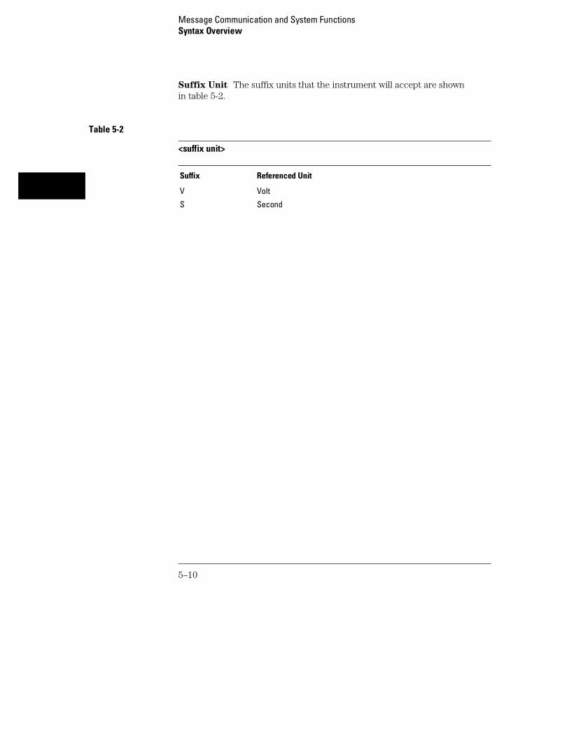
Suffix Unit The suffix units that the instrument will accept are shownin table 5-2.
Table 5-2
<suffix unit>
Suffix Referenced Unit
V Volt
S Second
Message Communication and System FunctionsSyntax Overview
5–10

6
Status Reporting

Introduction
Status reporting allows you to use information about the instrument inyour programs, so that you have better control of the measurementprocess. For example, you can use status reporting to determinewhen a measurement is complete, thus controlling your program, sothat it does not get ahead of the instrument. This chapter describesthe status registers, status bytes and status bits defined by IEEE488.2 and discusses how they are implemented in the 1660-serieslogic analyzers. Also in this chapter is a sample set of steps you use toperform a serial poll over GPIB.
The status reporting feature available over the bus is the serial poll.IEEE 488.2 defines data structures, commands, and common bitdefinitions. There are also instrument-defined structures and bits.
The bits in the status byte act as summary bits for the data structuresresiding behind them. In the case of queues, the summary bit is set ifthe queue is not empty. For registers, the summary bit is set if anyenabled bit in the event register is set. The events are enabled via thecorresponding event enable register. Events captured by an eventregister remain set until the register is read or cleared. Registers areread with their associated commands. The *CLS command clears allevent registers and all queues except the output queue. If *CLS issent immediately following a <program message terminator>, theoutput queue will also be cleared.
6–2
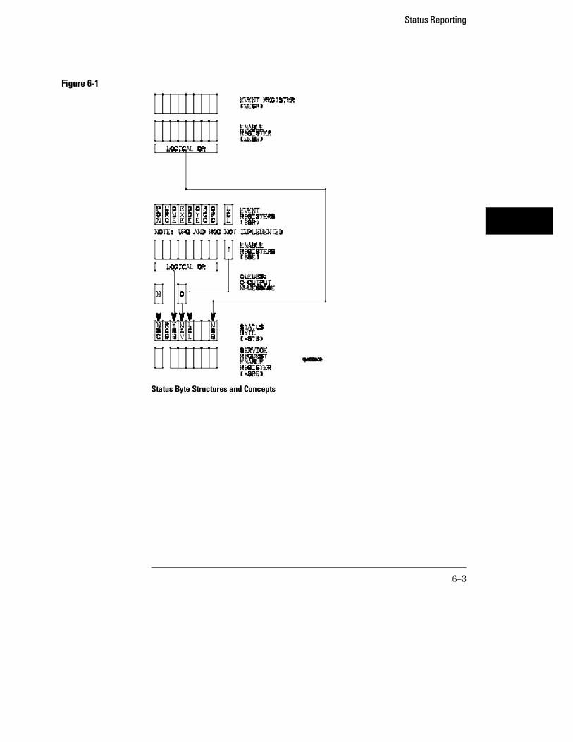
Figure 6-1
Status Byte Structures and Concepts
Status Reporting
6–3

Event Status Register
The Event Status Register is an IEEE 488.2 defined register. The bits in thisregister are "latched." That is, once an event happens which sets a bit, thatbit will only be cleared if the register is read.
Service Request Enable Register
The Service Request Enable Register is an 8-bit register. Each bit enablesthe corresponding bit in the status byte to cause a service request. The sixthbit does not logically exist and is always returned as a zero. To read andwrite to this register, use the *SRE? and *SRE commands.
Bit Definitions
The following mnemonics are used in figure 6-1 and in chapter 8, "CommonCommands:"
MAV - message available
Indicates whether there is a response in the output queue.
ESB - event status bit
Indicates if any of the conditions in the Standard Event Status Register areset and enabled.
MSS - master summary status
Indicates whether the device has a reason for requesting service. This bit isreturned for the *STB? query.
RQS - request service
Indicates if the device is requesting service. This bit is returned during aserial poll. RQS will be set to 0 after being read via a serial poll (MSS is notreset by *STB?).
Status ReportingEvent Status Register
6–4
MSG - message
Indicates whether there is a message in the message queue (Notimplemented in the 1660-series logic analyzers).
PON - power on
Indicates power has been turned on.
URQ - user request
Always returns a 0 from the 1660-series logic analyzer.
CME - command error
Indicates whether the parser detected an error.
The error numbers and strings for CME, EXE, DDE, and QYE can be read from adevice-defined queue (which is not part of IEEE 488.2) with the query:SYSTEM:ERROR?.
EXE - execution error
Indicates whether a parameter was out of range, or inconsistent with currentsettings.
DDE - device specific error
Indicates whether the device was unable to complete an operation for devicedependent reasons.
QYE - query error
Indicates whether the protocol for queries has been violated.
RQC - request control
Always returns a 0 from the 1660-series logic analyzer.
OPC - operation complete
Indicates whether the device has completed all pending operations. OPC iscontrolled by the *OPC common command. Because this command canappear after any other command, it serves as a general-purpose operationcomplete message generator.
Status ReportingBit Definitions
6–5

LCL - remote to local
Indicates whether a remote to local transition has occurred.
MSB - module summary bit
Indicates that an enable event in one of the modules Status registers hasoccurred.
Key Features
A few of the most important features of Status Reporting are listed in thefollowing paragraphs.
Operation Complete
The IEEE 488.2 structure provides one technique that can be used to findout if any operation is finished. The *OPC command, when sent to theinstrument after the operation of interest, will set the OPC bit in theStandard Event Status Register. If the OPC bit and the RQS bit have beenenabled, a service request will be generated. The commands that affect theOPC bit are the overlapped commands.
Example OUTPUT XXX;"*SRE 32 ; *ESE 1" !enables an OPC servicerequest
Status Byte
The Status Byte contains the basic status information which is sent over thebus in a serial poll. If the device is requesting service (RQS set), and thecontroller serial-polls the device, the RQS bit is cleared. The MSS (MasterSummary Status) bit (read with *STB?) and other bits of the Status Byte arenot be cleared by reading them. Only the RQS bit is cleared when read.
The Status Byte is cleared with the *CLS common command.
Status ReportingKey Features
6–6
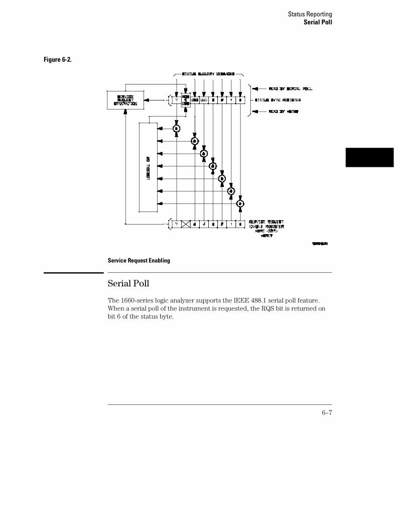
Figure 6-2.
Service Request Enabling
Serial Poll
The 1660-series logic analyzer supports the IEEE 488.1 serial poll feature.When a serial poll of the instrument is requested, the RQS bit is returned onbit 6 of the status byte.
Status ReportingSerial Poll
6–7
Using Serial Poll (GPIB)
This example will show how to use the service request by conducting a serialpoll of all instruments on the GPIB bus. In this example, assume that thereare two instruments on the bus: a Logic Analyzer at address 7 and a printer ataddress 1.
The program command for serial poll using HP BASIC 6.2 is Stat =SPOLL(707). The address 707 is the address of the logic analyzer in the thisexample. The command for checking the printer is Stat = SPOLL(701)because the address of that instrument is 01 on bus address 7. Thiscommand reads the contents of the GPIB Status Register into the variablecalled Stat. At that time bit 6 of the variable Stat can be tested to see if it isset (bit 6 = 1).
The serial poll operation can be conducted in the following manner:
1 Enable interrupts on the bus. This allows the controller to see theSRQ line.
2 Disable interrupts on the bus.3 If the SRQ line is high (some instrument is requesting service) then
check the instrument at address 1 to see if bit 6 of its status register ishigh.
4 To check whether bit 6 of an instruments status register is high, usethe following BASIC statement•: IF BIT (Stat, 6) THEN
5 If bit 6 of the instrument at address 1 is not high, then check theinstrument at address 7 to see if bit 6 of its status register is high.
6 As soon as the instrument with status bit 6 high is found check therest of the status bits to determine what is required.
The SPOLL(707) command causes much more to happen on the bus thansimply reading the register. This command clears the bus automatically,addresses the talker and listener, sends SPE (serial poll enable) and SPD(serial poll disable) bus commands, and reads the data. For moreinformation about serial poll, refer to your controller manual, andprogramming language reference manuals.
After the serial poll is completed, the RQS bit in the 1660-series logicanalyzer Status Byte Register will be reset if it was set. Once a bit in theStatus Byte Register is set, it will remain set until the status is cleared with a*CLS command, or the instrument is reset.
Status ReportingSerial Poll
6–8

7
Error Messages

Introduction
This chapter lists the error messages that relate to the 1660-serieslogic analyzers.
7–2

Device Dependent Errors
200 Label not found
201 Pattern string invalid
202 Qualifier invalid
203 Data not available
300 RS-232C error
Command Errors
–100 Command error (unknown command)(generic error)
–101 Invalid character received
–110 Command header error
–111 Header delimiter error
–120 Numeric argument error
–121 Wrong data type (numeric expected)
–123 Numeric overflow
–129 Missing numeric argument
–130 Non numeric argument error (character,string, or block)
–131 Wrong data type (character expected)
–132 Wrong data type (string expected)
–133 Wrong data type (block type #D required)
–134 Data overflow (string or block too long)
–139 Missing non numeric argument
–142 Too many arguments
–143 Argument delimiter error
–144 Invalid message unit delimiter
Error MessagesDevice Dependent Errors
7–3

Execution Errors
–200 Can Not Do (generic execution error)
–201 Not executable in Local Mode
–202 Settings lost due to return-to-local or power on
–203 Trigger ignored
–211 Legal command, but settings conflict
–212 Argument out of range
–221 Busy doing something else
–222 Insufficient capability or configuration
–232 Output buffer full or overflow
–240 Mass Memory error (generic)
–241 Mass storage device not present
–242 No media
–243 Bad media
–244 Media full
–245 Directory full
–246 File name not found
–247 Duplicate file name
–248 Media protected
Internal Errors
–300 Device Failure (generic hardware error)
–301 Interrupt fault
–302 System Error
–303 Time out
–310 RAM error
–311 RAM failure (hardware error)
–312 RAM data loss (software error)
–313 Calibration data loss
–320 ROM error
Error MessagesExecution Errors
7–4

–321 ROM checksum
–322 Hardware and Firmware incompatible
–330 Power on test failed
–340 Self Test failed
–350 Too Many Errors (Error queue overflow)
Query Errors
–400 Query Error (generic)
–410 Query INTERRUPTED
–420 Query UNTERMINATED
–421 Query received. Indefinite block response in progress
–422 Addressed to Talk, Nothing to Say
–430 Query DEADLOCKED
Error MessagesQuery Errors
7–5

7–6

Part 2
Mainframe Commands


8
Common Commands

Introduction
The common commands are defined by the IEEE 488.2 standard.These commands must be supported by all instruments that complywith this standard. Refer to figure 8-1 and table 8-1 for the commoncommands syntax diagram.
The common commands control some of the basic instrumentfunctions; such as, instrument identification and reset, how status isread and cleared, and how commands and queries are received andprocessed by the instrument. The common commands are:
• *CLS
• *ESE
• *ESR
• *IDN
• *IST
• *OPC
• *OPT
• *PRE
• *RST
• *SRE
• *STB
• *TRG
• *TST
• *WAI
Common commands can be received and processed by the 1660-serieslogic analyzers, whether they are sent over the bus as separateprogram messages or within other program messages. If aninstrument subsystem has been selected and a common command isreceived by the instrument, the logic analyzer will remain in theselected subsystem.
8–2

Example If the program message in this example is received by the logicanalyzer, it will initialize the disk and store the file and clear the statusinformation. This is not be the case if some other type of command isreceived within the program message.
":MMEMORY:INITIALIZE;*CLS; STORE ’FILE ’,’DESCRIPTION’"
Example This program message initializes the disk, selects the module in slot A,then stores the file. In this example, :MMEMORY must be sent againin order to reenter the memory subsystem and store the file.
":MMEMORY:INITIALIZE;:SELECT 1;:MMEMORY:STORE ’FILE ’,’DESCRIPTION’"
Status Registers
Each status register has an associated status enable (mask) register.By setting the bits in the status enable register you can select thestatus information you wish to use. Any status bits that have not beenmasked (enabled in the enable register) will not be used to reportstatus summary information to bits in other status registers.
Refer to chapter 6, "Status Reporting," for a complete discussion ofhow to read the status registers and how to use the status informationavailable from this instrument.
Common Commands
8–3

Figure 8-1
Common Commands Syntax Diagram
Common Commands
8–4

Table 8-1 Common Command Parameter Values
Parameter Values
mask An integer, 0 through 255.
pre_mask An integer, 0 through 65535.
*CLS (Clear Status)
Command *CLS
The *CLS common command clears all event status registers, queues, anddata structures, including the device defined error queue and status byte. Ifthe *CLS command immediately follows a <program message terminator>,the output queue and the MAV (Message Available) bit will be cleared. Referto chapter 6, "Status Reporting," for a complete discussion of status.
Example OUTPUT XXX;"*CLS"
Common Commands*CLS (Clear Status)
8–5

*ESE (Event Status Enable)
Command *ESE <mask>
The *ESE command sets the Standard Event Status Enable Register bits.The Standard Event Status Enable Register contains a bit to enable thestatus indicators detailed in table 8-2. A 1 in any bit position of the StandardEvent Status Enable Register enables the corresponding status in theStandard Event Status Enable Register. Refer to Chapter 6, "StatusReporting" for a complete discussion of status.
<mask> An integer from 0 to 255
Example In this example, the *ESE 32 command will enable CME (Command Error),bit 5 of the Standard Event Status Enable Register. Therefore, when acommand error occurs, the event summary bit (ESB) in the Status ByteRegister will also be set.OUTPUT XXX;"*ESE 32"
Query *ESE?
The *ESE query returns the current contents of the enable register.Returned Format <mask><NL>
Example OUTPUT XXX;"*ESE?"
Common Commands*ESE (Event Status Enable)
8–6

Table 8-2 Standard Event Status Enable Register
Bit Position Bit Weight Enables
7 128 PON - Power On
6 64 URQ - User Request
5 32 CME - Command Error
4 16 EXE - Execution Error
3 8 DDE - Device Dependent Error
2 4 QYE - Query Error
1 2 RQC - Request Control
0 1 OPC - Operation Complete
*ESR (Event Status Register)
Query *ESR?
The *ESR query returns the contents of the Standard Event Status Register.Reading the register clears the Standard Event Status Register.
Returned Format <status><NL>
<status> An integer from 0 to 255
Example If a command error has occurred, and bit 5 of the ESE register is set, thestring variable Esr_event$ will have bit 5 (the CME bit) set.10 OUTPUT XXX;"*ESE 32 !Enables bit 5 of the status register20 OUTPUT XXX;"*ESR?" !Queries the status register30 ENTER XXX; Esr_event$ !Reads the query buffer
Common Commands*ESR (Event Status Register)
8–7

Table 8-3 shows the Standard Event Status Register. The table details themeaning of each bit position in the Standard Event Status Register and thebit weight. When you read Standard Event Status Register, the valuereturned is the total bit weight of all the bits that are high at the time youread the byte.
Table 8-3 The Standard Event Status Register
Bit Position Bit Weight Bit Name Condition
7 128 PON 0 = register read - not in power up mode1 = power up
6 64 URQ 0 = user request - not used - always zero
5 32 CME 0 = no command errors1 = a command eror has been detected
4 16 EXE 0 = no execution errors1 = an execution error has been detected
3 8 DDE 0 = no device dependent error has been detected1 = a device dependent error has been detected
2 4 QYE 0 = no query errors1 = a query error has been detected
1 2 RQC 0 = request control - not used - always zero
0 1 OPC 0 = operation is not complete1 = operation is complete
Common Commands*ESR (Event Status Register)
8–8

*IDN (Identification Number)
Query *IDN?
The *IDN? query allows the instrument to identify itself. It returns the string:
"HEWLETT-PACKARD,1660A,0,REV <revision_code>"
An *IDN? query must be the last query in a message. Any queries after the*IDN? in the program message are ignored.
Returned Format HEWLETT-PACKARD,1660A,0,REV <revision code>
<revisioncode>
Four digit-code in the format XX.XX representing the current ROM revision.
Example OUTPUT XXX;"*IDN?"
*IST (Individual Status)
Query *IST?
The *IST query allows the instrument to identify itself during parallel poll byallowing the controller to read the current state of the IEEE 488.1 defined"ist" local message in the instrument. The response to this query isdependent upon the current status of the instrument.
Figure 8-2 shows the *IST data structure.Returned Format <id><NL>
<id> 0 or 1
1 Indicates the "ist" local message is false.
0 Indicates the "ist" local message is true.
Common Commands*IDN (Identification Number)
8–9

Example OUTPUT XXX;"*IST?"
Figure 8-2
*IST Data Structure
Common Commands*IST (Individual Status)
8–10

*OPC (Operation Complete)
Command *OPC
The *OPC command will cause the instrument to set the operation completebit in the Standard Event Status Register when all pending device operationshave finished. The commands which affect this bit are the overlappedcommands. An overlapped command is a command that allows execution ofsubsequent commands while the device operations initiated by theoverlapped command are still in progress. The overlapped commands for the1660-series logic analyzers are STARt and STOP.
Example OUTPUT XXX;"*OPC"
Query *OPC?
The *OPC query places an ASCII "1" in the output queue when all pendingdevice operations have been completed.
Returned Format 1<NL>
Example OUTPUT XXX;"*OPC?"
Common Commands*OPC (Operation Complete)
8–11

*OPT (Option Identification)
Query *OPT?
The *OPT query identifies the software installed in the 1660-series logicanalyzer. This query returns nine parameters. The first parameter indicateswhether you are in the system. The next two parameters indicate anysoftware options installed, and the next parameter indicates whetherintermodule is available for the system. The last five parameters list theinstalled software for the modules in slot A through E for an 16500A logicanalysis mainframe. However, the 1660-series logic analyzers have only twoslots (A and B); therefore, only the first and second parameters of the lastfive parameters will be relevant. A zero in any of the last eight parametersindicates that the corresponding software is not currently installed. Thename returned for software options and module software is the same namethat appears in the field in the upper-left corner of the menu for each optionor module.
Returned Format {SYSTEM},{<option>|0},{<option>|0},{INTERMODULE|0},{<module>|0},{<module>|0},{<module>|0},{<module>|0},{<module>|0}<NL>
<option> Name of software option.
<module> Name of module software.
Example OUTPUT XXX;"*OPT?"
Common Commands*OPT (Option Identification)
8–12

*PRE (Parallel Poll Enable Register Enable)
Command *PRE <mask>
The *PRE command sets the parallel poll register enable bits. The ParallelPoll Enable Register contains a mask value that is ANDed with the bits in theStatus Bit Register to enable an "ist" during a parallel poll. Refer to table 8-4for the bits in the Parallel Poll Enable Register and for what they mask.
<pre_mask> An integer from 0 to 65535.
Example This example will allow the 1660-series logic analyzers to generate an "ist"when a message is available in the output queue. When a message isavailable, the MAV (Message Available) bit in the Status Byte Register will behigh.Output XXX;"*PRE 16"
Query *PRE?
The *PRE? query returns the current value of the register.Returned format <mask><NL>
<mask> An integer from 0 through 65535 representing the sum of all bits that are set. .
Example OUTPUT XXX;"*PRE?"
Common Commands*PRE (Parallel Poll Enable Register Enable)
8–13

Table 8-4 1660-Series Logic Analyzer Parallel Poll Enable Register
Bit Position Bit Weight Enables
15 -8 Not used
7 128 Not used
6 64 MSS - Master Summary Status
5 32 ESB - Event Status
4 16 MAV - Message Available
3 8 LCL - Local
2 4 Not used
1 2 Not used
0 1 MSB - Module Summary
*RST (Reset)
The *RST command is not implemented on the 1660-series logic analyzer.The 1660-series logic analyzer will accept this command, but the commandhas no affect on the logic analyzer.
The *RST command is generally used to place the logic analyzer in apredefined state. Because the 1660-series logic analyzer allows you to storepredefined configuration files for individual modules, or for the entire system,resetting the logic analyzer can be accomplished by simply loading theappropriate configuration file. For more information, refer to chapter 11,"MMEMory Subsystem."
Common Commands*RST (Reset)
8–14
*SRE (Service Request Enable)
Command *SRE <mask>
The *SRE command sets the Service Request Enable Register bits. TheService Request Enable Register contains a mask value for the bits to beenabled in the Status Byte Register. A one in the Service Request EnableRegister will enable the corresponding bit in the Status Byte Register. A zerowill disable the bit. Refer to table 8-5 for the bits in the Service RequestEnable Register and what they mask.
Refer to Chapter 6, "Status Reporting," for a complete discussion of status.
<mask> An integer from 0 to 255
Example This example enables a service request to be generated when a message isavailable in the output queue. When a message is available, the MAV(Message Available) bit will be high.
OUTPUT XXX;"*SRE 16"
Query *SRE?
The *SRE query returns the current value.Returned Format <mask><NL>
<mask> An integer from 0 to 255 representing the sum of all bits that are set.
Example OUTPUT XXX;"*SRE?"
Common Commands*SRE (Service Request Enable)
8–15

Table 8-5 1660-Series Logic Analyzer Service Request Enable Register
Bit Position Bit Weight Enables
15-8 not used
7 128 not used
6 64 MSS - Master Summary Status (always 0)
5 32 ESB - Event Status
4 16 MAV - Message Available
3 8 LCL- Local
2 4 not used
1 2 not used
0 1 MSB - Module Summary
*STB (Status Byte)
Query *STB?
The *STB query returns the current value of the instrument’s status byte.The MSS (Master Summary Status) bit, and, not the RQS (Request Service)bit is reported on bit 6. The MSS indicates whether or not the device has atleast one reason for requesting service. Refer to table 8-6 for the meaning ofthe bits in the status byte.
Refer to Chapter 6, "Status Reporting" for a complete discussion of status.Returned Format <value><NL>
<value> An integer from 0 through 255
Example OUTPUT XXX;"*STB?"
Common Commands*STB (Status Byte)
8–16

Table 8-6 The Status Byte Register
Bit Position Bit Weight Bit Name Condition
7 128 0 = not Used
6 64 MSS 0 = instrument has no reason for service1 = instrument is requesting service
5 32 ESB 0 = no event status conditions have occurred1 = an enabled event status condition has occurred
4 16 MAV 0 = no output messages are ready1 = an output message is ready
3 8 LCL 0 = a remote-to-local transition has not occurred1 = a remote-to-local transition has occurred
2 4 not used
1 2 not used
0 1 MSB 0 = a module or the system has activity to report1 = no activity to report
0 = False = Low1 = True = High
*TRG (Trigger)
Command *TRG
The *TRG command has the same effect as a Group Execute Trigger (GET).That effect is as if the START command had been sent for intermodule grouprun. If no modules are configured in the Intermodule menu, this commandhas no effect.
Example OUTPUT XXX;"*TRG"
Common Commands*TRG (Trigger)
8–17
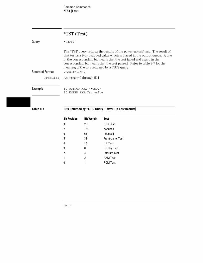
*TST (Test)
Query *TST?
The *TST query returns the results of the power-up self-test. The result ofthat test is a 9-bit mapped value which is placed in the output queue. A onein the corresponding bit means that the test failed and a zero in thecorresponding bit means that the test passed. Refer to table 8-7 for themeaning of the bits returned by a TST? query.
Returned Format <result><NL>
<result> An integer 0 through 511
Example 10 OUTPUT XXX;"*TST?"20 ENTER XXX;Tst_value
Table 8-7 Bits Returned by *TST? Query (Power-Up Test Results)
Bit Position Bit Weight Test
8 256 Disk Test
7 128 not used
6 64 not used
5 32 Front-panel Test
4 16 HIL Test
3 8 Display Test
2 4 Interupt Test
1 2 RAM Test
0 1 ROM Test
Common Commands*TST (Test)
8–18

*WAI (Wait)
Command *WAI
The *WAI command causes the device to wait until completing all of theoverlapped commands before executing any further commands or queries.An overlapped command is a command that allows execution of subsequentcommands while the device operations initiated by the overlapped commandare still in progress. Some examples of overlapped commands for the1660-series logic analyzers are STARt and STOP.
Example: OUTPUT XXX;"*WAI"
Common Commands*WAI (Wait)
8–19

8–20

9
Mainframe Commands

Introduction
Mainframe commands control the basic operation of the instrumentfor the 1660-series logic analyzers. The 1660-series logic analyzers aresimilar to a 16500A logic analysis system with either a single logicanalyzer module (1660A) or one logic analyzer and one oscilloscopemodule (1660AS) installed.
The main difference in mainframe commands for the 1660-series logicanalyzers is the number of modules. In the 1660 series logic analyzers,module 0 contains the system level commands, module 1 contains thelogic analyzer level commands, and module 2 contains theoscilloscope module commands. The command parser in the1660-series logic analyzers is designed to accept programs written forthe 16500A logic analysis system with a 16550A logic analyzer and/oroscilloscope modules. The main difference is how you specify theSELECT command. Remember, the 1660-series logic analyzer isequivalent only to a mainframe with up to two modules; therefore, ifyou specify 3 through 10 for the SELECT command in your program,the command parser will take no action.
This chapter contains mainframe commands with a syntax examplefor each command. Each syntax example contains parameters for the1600-series logic analyzers only. Refer to figure 9-1 and table 9-1 forthe Mainframe commands syntax diagram. The mainframe commandsare:
• BEEPer • MESE• CAPability • MESR• CARDcage • RMODe• CESE • RTC• CESR • SELect• EOI • SETColor• LER • STARt• LOCKout • STOP• MENU
9–2

Figure 9-1
Mainframe Commands Syntax Diagram
Mainframe Commands
9–3

Figure 9-1 (continued)
Mainframe Commands Syntax Diagram (continued)
Mainframe Commands
9–4

Table 9-1 Mainframe Parameter Values
Parameter Values
value An integer from 0 to 65535.
module An integer 0 through 2 (3 through 10 unused).
menu An integer.
enable_value An integer from 0 to 255.
index An integer from 0 to 5.
day An integer from 1 through 31
month An integer from 1 through 12
year An integer from 1990 through 2089
hour An integer from 0 through 23
minute An integer from 0 through 59
second An integer from 0 through 59
color An integer from 1 to 7.
hue An integer from 0 to 100.
sat An integer from 0 to 100.
lum An integer from 0 to 100.
Mainframe Commands
9–5

BEEPer
Command :BEEPer [{ON|1}|{OFF|0}]
The BEEPer command sets the beeper mode, which turns the beeper soundof the instrument on and off. When BEEPer is sent with no argument, thebeeper will be sounded without affecting the current mode.
Example OUTPUT XXX;":BEEPER"OUTPUT XXX;":BEEP ON"
Query :BEEPer?
The BEEPer? query returns the mode currently selected.Returned Format [:BEEPer] {1|0}<NL>
Example OUTPUT XXX;":BEEPER?"
Mainframe CommandsBEEPer
9–6

CAPability
Query :CAPability?
The CAPability query returns the HP-SL (HP System Language) and lowerlevel capability sets implemented in the device.
Table 9-2 lists the capability sets implemented in the 1660-series logicanalyzers.
Returned Format [:CAPability]IEEE488,1987,SH1,AH1,T5,L4,SR1,RL1,PP1,DC1,DT1,C0,E2<NL>
Example OUTPUT XXX;":CAPABILITY?"
Table 9-2 1660-Series Logic Analyzer Capability Sets
Mnemonic Capability Name Implementation
SH Source Handshake SH1
AH Acceptor Handshake AH1
T Talker (or TE - Extended Talker) T5
L Listener (or LE - Extended Listener) L4
SR Service Request SR1
RL Remote Local RL1
PP Parallel Poll PP1
DC Device Clear DC1
DT Device Trigger DT1
C Any Controller C0
E Electrical Characteristic E2
Mainframe CommandsCAPability
9–7

CARDcage
Query :CARDcage?
The CARDcage query returns a series of integers which identify the modulesthat are installed in the mainframe. The returned string is in two parts. Thefirst five two-digit numbers identify the card type. The identification numberfor the logic analyzer is 32. The identification number for the oscilloscope is13. A "-1" in the first part of the string indicates no card is installed in theslot.
The five single-digit numbers in the second part of the string indicate whichslots have cards installed. The module assignment for the logic analyzer willalways be 1. The second number will contain a 0 unless the oscilloscopemodule is installed (1660AS), in which case it will return a 1. The possiblevalues for the module assignment are 0 and 1 where 0 indicates the modulesoftware is not recognized or not loaded.
Returned Format [:CARDcage]<ID>,<ID>,<ID>,<ID>,<ID><assign>,<assign>,<assign>,<assign>,<assign><NL>
<ID> An integer indicating the card identification number.
<assign> An integer indicating the module assignment.
Example OUTPUT XXX;":CARDCAGE?"
Mainframe CommandsCARDcage
9–8

CESE (Combined Event Status Enable)
Command :CESE <value>
The CESE command sets the Combined Event Status Enable register. Thisregister is the enable register for the CESR register and contains thecombined status of all of the MESE (Module Event Status Enable) registersof the 1660-series logic analyzer. Table 9-3 lists the bit values for the CESEregister.
<value> An integer from 0 to 65535
Example OUTPUT XXX;":CESE 32"
Query :CESE?
The CESE? query returns the current setting.Returned Format [:CESE] <value><NL>
Example OUTPUT XXX;":CESE?"
Table 9-3 1660-Series Logic Analyzer Combined Event Status Enable Register
Bit Weight Enables
3 to 15 not used
2 4 oscilloscope
1 2 logic analyzer
0 1 Intermodule
Mainframe CommandsCESE (Combined Event Status Enable)
9–9

CESR (Combined Event Status Register)
Query :CESR?
The CESR query returns the contents of the Combined Event Status register.This register contains the combined status of all of the MESRs (Module EventStatus Registers) of the 1660-series logic analyzer. Table 9-4 lists the bitvalues for the CESR register.
Returned Format [:CESR] <value><NL>
<value> An integer from 0 to 65535
Example OUTPUT XXX;":CESR?"
Table 9-4 1660-Series Logic Analyzer Combined Event Status Register
Bit Bit Weight Bit Name Condition
3 to 15 0 = not used
2 4 Oscilloscope 0 = No new status1 = Status to report
1 2 Logic analyzer 0 = No new status1 = Status to report
0 1 Intermodule 0 = No new status1 = Status to report
Mainframe CommandsCESR (Combined Event Status Register)
9–10

EOI (End Or Identify)
Command :EOI {{ON|1}|{OFF|0}}
The EOI command specifies whether or not the last byte of a reply from theinstrument is to be sent with the EOI bus control line set true or not. If EOIis turned off, the logic analyzer will no longer be sending IEEE 488.2compliant responses.
Example OUTPUT XXX;":EOI ON"
Query :EOI?
The EOI? query returns the current status of EOI.Returned Format [:EOI] {1|0}<NL>
Example OUTPUT XXX;":EOI?"
LER (LCL Event Register)
Query :LER?
The LER query allows the LCL Event Register to be read. After the LCLEvent Register is read, it is cleared. A one indicates a remote-to-localtransition has taken place. A zero indicates a remote-to-local transition hasnot taken place.
Returned Format [:LER] {0|1}<NL>
Example OUTPUT XXX;":LER?"
Mainframe CommandsEOI (End Or Identify)
9–11

LOCKout
Command :LOCKout {{ON|1}|{OFF|0}}
The LOCKout command locks out or restores front panel operation. Whenthis function is on, all controls (except the power switch) are entirely lockedout.
Example OUTPUT XXX;":LOCKOUT ON"
Query :LOCKout?
The LOCKout query returns the current status of the LOCKout command.Returned Format [:LOCKout] {0|1}<NL>
Example OUTPUT XXX;":LOCKOUT?"
MENU
Command :MENU <module>[,<menu>]
The MENU command puts a menu on the display. The first parameterspecifies the desired module. The optional second parameter specifies thedesired menu in the module (defaults to 0). Table 9-5 lists the parametersand the menus.
<module> Selects module or system (integer) 0 selects the system, 1 selects the logicanalyzer, and 2 selects the oscilloscope. –2, –1 and 3 to 10 unused)
<menu> Selects menu (integer)
Mainframe CommandsLOCKout
9–12

Example OUTPUT XXX;":MENU 0,1"
Table 9-5 Menu Parameter Values
Parameters Menu
0,0 System RS-232/GPIB
0,2 System Disk
0,3 System Utilities
0,4 System Test
1,0 Analyzer Configuration
1,1 Format 1
1,2 Format 2
1,3 Trigger 1
1,4 Trigger 2
1,5 Waveform 1
1,6 Waveform 2
1,7 Listing 1
1,8 Listing 2
1,9 Mixed
1,10 Compare 1
1,11 Compare 2
1,12 Chart 1
1,13 Chart 2
2,0 Channel
2,1 Trigger
2,2 Display
2,3 Auto-measure
2,4 Marker
2,5 Calibration
Mainframe CommandsMENU
9–13

Query :MENU?
The MENU query returns the current menu selection. Returned Format [:MENU] <module>,<menu><NL>
Example OUTPUT XXX;":MENU?"
MESE<N> (Module Event Status Enable)
Command :MESE<N> <enable_value>
The MESE command sets the Module Event Status Enable register. Thisregister is the enable register for the MESR register. The <N> indexspecifies the module, and the parameter specifies the enable value. For the1660-series logic analyzer, the <N> index 0, 1, or 2 refers to system, logicanalyzer, or oscilloscope respectively.
<N> An integer 0 through 2 (3 through 10 unused).
<enable_value> An integer from 0 through 255
Example OUTPUT XXX;":MESE1 3"
Query :MESE<N>?
The query returns the current setting. Tables 9-6, 9-7, and 9-8 list theModule Event Status Enable register bits, bit weights, and what each bitmasks for the mainframe, logic analyzer, and oscilloscope respectively.
Returned Format [:MESE<N>] <enable_value><NL>
Example OUTPUT XXX;":MESE1?"
Mainframe CommandsMESE<N> (Module Event Status Enable)
9–14

Table 9-6 1660-Series Mainframe (Intermodule) Module Event Status Enable Register
Bit Position Bit Weight Enables
7 128 not used
6 84 not used
5 32 not used
4 16 not used
3 8 not used
2 4 not used
1 2 RNT - Intermodule Run Until Satisfied
0 1 MC - Intermodule Measurement Complete
Table 9-7 1660-Series Logic Analyzer Module Event Status Enable Register
Bit Position Bit Weight Enables
7 128 not used
6 84 not used
5 32 not used
4 16 not used
3 8 Pattern searches failed
2 4 Trigger found
1 2 RNT - Run Until Satisfied
0 1 MC - Measurement Complete
Mainframe CommandsMESE<N> (Module Event Status Enable)
9–15

Table 9-8 1660-Series Oscilloscope Module Event Status Enable Register
Bit Position Bit Weight Enables
7 128 not used
6 84 not used
5 32 not used
4 16 Number of averages met
3 8 Auto triggered
2 4 Trigger received
1 2 RNT - Run Until Satisfied
0 1 MC - Measurement Complete
MESR<N> (Module Event Status Register)
Query :MESR<N>?
The MESR query returns the contents of the Module Event Status register.The <N> index specifies the module. For the 1660 series logic analyzer, the<N> index 0, 1, or 2 refers to system, logic analyzer, or oscilloscoperespectively.
Refer to table 9-9 for information about the Module Event Status Registerbits and their bit weights for the system, table 9-10 for the logic analyzer, andtable 9-11 for the oscilloscope.
Returned Format [:MESR<N>] <enable_value><NL>
<N> An integer 0 through 10 (3 through 10 unused).
<enable_value> An integer from 0 through 255
Example OUTPUT XXX;":MESR1?"
Mainframe CommandsMESR<N> (Module Event Status Register)
9–16

Table 9-9 1660-Series Logic Analyzer Mainframe Module Event Status Register
Bit Bit Weight Bit Name Condition
7 128 0 = not used
6 64 0 = not used
5 32 0 = not used
4 16 0 = not used
3 8 0 = not used
2 4 0 = not used
1 2 RNT 0 = Intermodule Run until not satisfied1 = Intermodule Run until satisfied
0 1 MC 0 = Intermodule Measurement not satisfied1 = Intermodule Measurement satisfied
Table 9-10 1660-Series Logic Analyzer Module Event Status Register
Bit Bit Weight Condition
7 128 0 = not used
6 64 0 = not used
5 32 0 = not used
4 16 0 = not used
3 8 1 = One or more pattern searches failed0 = Pattern searches did not fail
2 4 1 = Trigger found0 = Trigger not found
1 2 0 = Run until not satisfied1 = Run until satisfied
0 1 0 = Measurement not satisfied1 = Measurement satisfied
Mainframe CommandsMESR<N> (Module Event Status Register)
9–17

Table 9-11 1660-Series Oscilloscope Module Event Status Register
Bit Bit Weight Bit Name Condition
7 128 0 = not used
6 64 0 = not used
5 32 0 = not used
4 16 1 = Number of averages satisfied0= Number of averages not satisfied
3 8 1 = Auto trigger received0= Auto trigger not received
2 4 1= Trigger received0= Trigger not received
1 2 RNT 1 = Run until satisfied0 = Run until not satisfied
0 1 MC 1 = Measurement complete0 = Measurement not complete
RMODe
Command :RMODe {SINGle|REPetitive}
The RMODe command specifies the run mode for the selected module (orIntermodule). If the selected module is in the intermodule configuration,then the intermodule run mode will be set by this command.
After specifying the run mode, use the STARt command to start the acquisition.
Example OUTPUT XXX;":RMODE SINGLE"
Mainframe CommandsRMODe
9–18

Query :RMODe?
The query returns the current setting.Returned Format [:RMODe] {SINGle|REPetitive}<NL>
Example OUTPUT XXX;":RMODE?"
RTC (Real-time Clock)
Command :RTC {<day>,<month>,<year>,<hour>,<minute>,<second>|DEFault}
The real-time clock command allows you to set the real-time clock to thecurrent date and time. The DEFault option sets the real-time clock to 01January 1990, 12:00:00 (24-hour format).
<day> integer from 1 to 31
<month> integer from 1 to 12
<year> integer from 1990 to 2089
<hour> integer from 0 to 23
<minute> integer from 0 to 59
<second> integer from 0 to 59
Example This example sets the real-time clock for 1 January 1992, 20:00:00 (8 PM).
OUTPUT XXX;":RTC 1,1,1992,20,0,0"
Mainframe CommandsRTC (Real-time Clock)
9–19

Query :RTC?
The RTC query returns the real-time clock setting.Returned Format [:RTC] <day>,<month>,<year>,<hour>,<minute>,<second>
Example OUTPUT XXX;":RTC?"
SELect
Command :SELect <module>
The SELect command selects which module (or system) will have parsercontrol. SELect defaults to System (0) at power up. The appropriate module(or system) must be selected before any module (or system) specificcommands can be sent. SELECT 0 selects the System, SELECT 1 selects thelogic analyzer (state and timing), and SELECT 2 selects the oscilloscopemodule. Select –2, –1 and, 3 through 10 are accepted but no action will betaken. When a module is selected, the parser recognizes the module’scommands and the System/Intermodule commands. When SELECT 0 isused, only the System/Intermodule commands are recognized by the parser.Figure 9-2 shows the command tree for the SELect command.
The command parser in the 1660-series logic analyzers is designed to acceptprograms written for the 16500A logic analysis system with a 16550A logicanalyzer module; however, if the parameters 3 through 10 are sent, the1660-series logic analyzer will take no action.
<module> An integer 0 through 2 (–2, –1, and 3 through 10 unused).
Example OUTPUT XXX;":SELECT 0"
Mainframe CommandsSELect
9–20

Query :SELect?
The SELect? query returns the current module selection. Returned Format [:SELect] <module><NL>
Example OUTPUT XXX;":SELECT?"
Figure 9-2
Select Command Tree
Not Used
Mainframe CommandsSELect
9–21

SETColor
Command :SETColor {<color>,<hue>,<sat>,<lum>|DEFault}
The SETColor command is used to change one of the selections on the CRT,or to return to the default screen colors. Four parameters are sent with thecommand to change a color:
• Color Number (first parameter)
• Hue (second parameter)
• Saturation (third parameter)
• Luminosity (last parameter)
<color> An integer from 1 to 7
<hue> An integer from 0 to 100.
<sat> An integer from 0 to 100.
<lum> An integer from 0 to 100
Color Number 0 cannot be changed.
Example OUTPUT XXX;":SETCOLOR 3,60,100,60"OUTPUT XXX;":SETC DEFAULT"
Query :SETColor? <color>
The SETColor query returns the luminosity values for a specified grey scale. Returned Format [:SETColor] <color>,<hue>,<sat>,<lum><NL>
Example OUTPUT XXX;":SETCOLOR? 3"
Mainframe CommandsSETColor
9–22

STARt
Command :STARt
The STARt command starts the selected module (or Intermodule) running inthe specified run mode (see RMODe). If the specified module is in theIntermodule configuration, then the Intermodule run will be started.
The STARt command is an overlapped command. An overlapped command is acommand that allows execution of subsequent commands while the deviceoperations initiated by the overlapped command are still in progress.
Example OUTPUT XXX;":START"
Mainframe CommandsSTARt
9–23

STOP
Command :STOP
The STOP command stops the selected module (or Intermodule). If thespecified module is in the Intermodule configuration, then the Intermodulerun will be stopped.
The STOP command is an overlapped command. An overlapped command is acommand that allows execution of subsequent commands while the deviceoperations initiated by the overlapped command are still in progress.
Example OUTPUT XXX;":STOP"
Mainframe CommandsSTOP
9–24

10
SYSTem Subsystem

Introduction
SYSTem subsystem commands control functions that are common tothe entire 1660-Series logic analysis system, including formattingquery responses and enabling reading and writing to the advisory lineof the instrument. The command parser in the 1660-series logicanalyzer is designed to accept programs written for the 16500A logicanalysis system with a 16550A logic analyzer module and a 16532Aoscilloscope module.
Refer to figure 10-1 and table 10-1 for the System Subsystemcommands syntax diagram. The SYSTem Subsystem commands are:
• DATA
• DSP
• ERRor
• HEADer
• LONGform
• SETup
10–2

Figure 10-1
System Subsystem Commands Syntax Diagram
SYSTem Subsystem
10–3

System Subsystem Commands Syntax Diagram (Continued)
Table 10-1 SYSTem Parameter Values
Parameter Values
block_data Data in IEEE 488.2 format.
string A string of up to 68 alphanumeric characters.
SYSTem Subsystem
10–4

DATA
Command :SYSTem:DATA <block_data>
The DATA command allows you to send and receive acquired data to andfrom a controller in block form. This helps saving block data for:
• Reloading to the logic analyzer or oscilloscope
• Processing data later in the logic analyzer or oscilloscope
• Processing data in the controller.
The format and length of block data depends on the instruction being usedand the configuration of the instrument. This chapter describes briefly thesyntax of the Data command and query. Because the mainframe by itselfdoes not have acquired data, and the capabilities of the DATA command andquery vary for each module, the DATA command and query are described indetail in the respective modules command section. See chapter 26, "DATAand SETup Commands" for additional information when using the logicanalyzer, or chapter 35, "WAVeform Subsystem" when using the oscilloscopemodule.
Example OUTPUT XXX;":SYSTEM:DATA" <block_data>
<block_data> <block_length_specifier><section>
<block_length_ specifier>
#8<length>
<length> The total length of all sections in byte format (must be represented with 8digits)
<section> <section_header><section_data>
<section_header>
16 bytes, described in the "Section Header Description" section in theindividual modules command section.
<section_data> The format depends on the type of data
SYSTem SubsystemDATA
10–5

Query :SYSTem:DATA?
The SYSTem:DATA query returns the block data. The data sent by theSYSTem:DATA query reflects the configuration of the machines when thelast run was performed. Any changes made since then through eitherfront-panel operations or programming commands do not affect the storedconfiguration.
Returned Format [:SYSTem:DATA] <block_data><NL>
Example See chapter 36, "Programming Examples" for an example on transferring data.
DSP (Display)
Command :SYSTem:DSP <string>
The DSP command writes the specified quoted string to a device-dependentportion of the instrument display.
<string> A string of up to 68 alphanumeric characters
Example OUTPUT XXX;":SYSTEM:DSP ’The message goes here’"
SYSTem SubsystemDSP (Display)
10–6

ERRor
Query :SYSTem:ERRor? [NUMeric|STRing]
The ERRor query returns the oldest error from the error queue. The optionalparameter determines whether the error string should be returned along withthe error number. If no parameter is received, or if the parameter isNUMeric, then only the error number is returned. If the value of theparameter is STRing, then the error should be returned in the following form:
<error_number>,<error_message (string)>
A complete list of error messages for the 1660A-series logic analyzer is shownin chapter 7, "Error Messages." If no errors are present in the error queue, azero (No Error) is returned.
Returned Formats Numeric:[:SYSTem:ERRor] <error_number><NL>
String:[:SYSTem:ERRor] <error_number>,<error_string><NL>
<error_number> An integer
<error_string> A string of alphanumeric characters
Examples Numeric:
10 OUTPUT XXX;":SYSTEM:ERROR?" 20 ENTER XXX;Numeric
String:50 OUTPUT XXX;":SYST:ERR? STRING"60 ENTER XXX;String$
SYSTem SubsystemERRor
10–7

HEADer
Command :SYSTem:HEADer {{ON|1}|{OFF|0}}
The HEADer command tells the instrument whether or not to output aheader for query responses. When HEADer is set to ON, query responses willinclude the command header.
Example OUTPUT XXX;":SYSTEM:HEADER ON"
Query :SYSTem:HEADer?
The HEADer query returns the current state of the HEADer command.Returned Format [:SYSTem:HEADer] {1|0}<NL>
Example OUTPUT XXX;":SYSTEM:HEADER?"
Headers should be turned off when returning values to numeric variables.
SYSTem SubsystemHEADer
10–8

LONGform
Command :SYSTem:LONGform {{ON|1}|{OFF|0}}
The LONGform command sets the longform variable, which tells theinstrument how to format query responses. If the LONGform command is setto OFF, command headers and alpha arguments are sent from the instrumentin the abbreviated form. If the the LONGform command is set to ON, thewhole word will be output. This command has no affect on the input datamessages to the instrument. Headers and arguments may be input in eitherthe longform or shortform regardless of how the LONGform command is set.
Example OUTPUT XXX;":SYSTEM:LONGFORM ON"
Query :SYSTem:LONGform?
The query returns the status of the LONGform command.Returned Format [:SYSTem:LONGform] {1|0}<NL>
Example OUTPUT XXX;":SYSTEM:LONGFORM?"
SYSTem SubsystemLONGform
10–9

Command :SYSTem:PRINt {ALL|PARTial,<start>,<end>},DISK,<pathname>:SYSTem:PRINt SCReen{BTIF|CTIF|PCX|EPS},DISK,<pathname>
The PRINt command initiates a print of the screen or listing buffer over thecurrent PRINTER communication interface to the printer or to a file on thedisk. The PRINT SCREEN option allows you to specify a graphics type. BTIF format is black & white, CTIF and PCX format is color. If a fileextension is not specified, one is appended automatically to the file name.The PRINT PARTIAL option allows you to specify a START and END statenumber.
<pathname> A string of up to 10 alphanumeric characters for LIF in the following form:NNNNNNNNNN when the file resides in the present working directory, or astring of up to 64 alphanumeric characters for DOS in the following forms:NNNNNNNN.NNN or \NAME_DIR|FILENAME when the file does not residein the present working directory.
<start>, <end> An integer specifying a state number.
Example This instuctrion prints the screen to the printer:OUTPUT XXX;":SYSTEM:PRINT SCREEN"
This instruction prints all, to a file named STATE:OUTPUT 707;":SYSTEM:PRINT ALL, DISK,’STATE’"
This instruction prints partial data to a file named LIST.OUTPUT 707;":SYSTEM:PRINT PARTIAL,-9,30, DISK,’list’
Query :SYSTem:PRINt? {SCReen|ALL}
The PRINt query sends the screen or listing buffer data over the currentCONTROLLER communication interface to the controller.
SYSTem SubsystemPRINt
10–10

The print query should NOT be sent with any other command or query on thesame command line. The print query never returns a header. Also, sinceresponse data from a print query may be sent directly to a printer withoutmodification, the data is not returned in block mode.
Example OUTPUT 707;":SYSTEM:PRINT? SCREEN"
SETup
Command :SYStem:SETup <block_data>
The :SYStem:SETup command configures the logic analyzer module asdefined by the block data sent by the controller. This chapter describesbriefly the syntax of the Setup command and query. Because of thecapabilites and importance of the Setup command and query, a completechapter is dedicated to it. The dedicated chapter is chapter 26, "DATA andSETup Commands."
<block_data> <block_length_specifier><section>
<block_length_ specifier>
#8<length>
<length> The total length of all sections in byte format (must be represented with 8digits)
<section> <section_header><section_data>
<section_header>
16 bytes, described in the "Section Header Description" section in chapter 26.
<section_data> Format depends on the type of data
SYSTem SubsystemSETup
10–11

The total length of a section is 16 (for the section header) plus the length ofthe section data. So when calculating the value for <length>, don’t forgetto include the length of the section headers.
Example OUTPUT XXX USING "#,K";":SYSTEM:SETUP " <block_data>
Query :SYStem:SETup?
The SYStem:SETup query returns a block of data that contains the currentconfiguration to the controller.
Returned Format [:SYStem:SETup] <block_data><NL>
Example See "Transferring the logic analyzer configuration" in chapter 27,"Programming Examples" for an example.
SYSTem SubsystemSETup
10–12

11
MMEMory Subsystem

Introduction
The MMEMory (mass memory) subsystem commands provide accessto disk drive. The 1600-series logic analyzers support both LIF(Logical Information Format) and DOS (Disk Operating System)formats.
The 1660-series logic analyzers have only one disk drive; however,programs written for the 16500A logic analysis system that containthe MSI (Mass Storage Is) parameter will be accepted but no action istaken. Refer to figure 11-1 and table 11-1 for the MMEMorySubsystem commands syntax diagram. The MMEMory subsystemcommands are:
• AUToload
• CATalog
• COPY
• DOWNload
• INITialize
• LOAD
• MSI
• PACK
• PURGe
• REName
• STORe
• UPLoad
• VOLume
11–2

<msus> refers to the mass storage unit specifier; however, it is not needed forthe 1660-series logic analyzers since they have only one drive. The <msus>parameter is shown in the command syntax examples as a reminder that for thethe 16500A logic analysis system can be used on the 1660-series logic analyzers.
If you are not going to store information to the configuration disk, or if the diskyou are using contains information you need, it is advisable to write protectyour disk. This will protect the contents of the disk from accidental damage dueto incorrect commands being mistakenly sent.
MMEMory Subsystem
11–3

Figure 11-1
Mmemory Subsystem Commands Syntax Diagram
MMEMory Subsystem
11–4

Figure 11-1
Mmemory Subsystem Commands Syntax Diagram (Continued)
MMEMory Subsystem
11–5
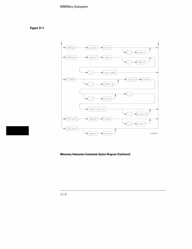
Figure 11-1
Mmemory Subsystem Commands Syntax Diagram (Continued)
MMEMory Subsystem
11–6

Table 11-1 MMEMory Parameter Values
Parameter Values
auto_file A string of up to 10 alphanumeric characters for LIF in thefollowing form: "NNNNNNNNNN"orA string of up to 12 alphanumeric characters for DOS in thefollowing form: "NNNNNNNN.NNN"
msus Mass Storage Unit specifier (not needed by 1660-series.16500A <msus> is accepted but no action is taken).
name A string of up to 10 alphanumeric characters for LIF in thefollowing form: "NNNNNNNNNN"orA string of up to 12 alphanumeric characters for DOS in thefollowing form: "NNNNNNNN.NNN"
description A string of up to 32 alphanumeric characters.
type An integer, refer to table 11-2.
block_data Data in IEEE 488.2 format.
ia_name A string of up to 10 alphanumeric characters for LIF in thefollowing form: "NNNNNNNNNN"orA string of up to 12 alphanumeric characters for DOS in thefollowing form: "NNNNNNNN.NNN"
new_name A string of up to 10 alphanumeric characters for LIF in thefollowing form: "NNNNNNNNNN"orA string of up to 12 alphanumeric characters for DOS in thefollowing form: "NNNNNNNN.NNN"
module An integer, 0 through 2.
MMEMory Subsystem
11–7

AUToload
Command :MMEMory:AUToload {{OFF|0}|{<auto_file>}}[,<msus>]
The AUToload command controls the autoload feature which designates a setof configuration files to be loaded automatically the next time the instrumentis turned on. The OFF parameter (or 0) disables the autoload feature. Astring parameter may be specified instead to represent the desired autoloadfile. If the file is on the current disk, the autoload feature is enabled to thespecified file.
<auto_file> A string of up to 10 alphanumeric characters for LIF in the following form:
NNNNNNNNNNorA string of up to 12 alphanumeric characters for DOS in the following form:
NNNNNNNN.NNN
<msus> Mass Storage Unit Specifier (not needed by 1660-series. 16500A <msus> isaccepted but no action is taken).
Examples OUTPUT XXX;":MMEMORY:AUTOLOAD OFF"OUTPUT XXX;":MMEMORY:AUTOLOAD ’FILE1_A’" OUTPUT XXX;":MMEMORY:AUTOLOAD ’FILE2 ’,INTERNAL0"
Query :MMEMory:AUToload?
The AUToload query returns 0 if the autoload feature is disabled. If theautoload feature is enabled, the query returns a string parameter thatspecifies the current autoload file. The appropriate slot designator isincluded in the filename and refers to the slot designator A for the logicanalyzer or B for the oscilloscope. If the slot designator is _ (underscore)the file is for the system.
Returned Format [:MMEMory:AUToload] {0|<auto_file>},<msus><NL>
MMEMory SubsystemAUToload
11–8

<auto_file> A string of up to 10 alphanumeric characters for LIF in the following form:
NNNNNNNNNNorA string of up to 12 alphanumeric characters for DOS in the following form:
NNNNNNNN.NNN
Example OUTPUT XXX;":MMEMORY:AUTOLOAD?"
CATalog
Query :MMEMory:CATalog? [[All,][<msus>]]
The CATalog query returns the directory of the disk in one of two block dataformats. The directory consists of a 51 character string for each file on thedisk when the ALL option is not used. Each file entry is formatted as follows:
"NNNNNNNNNN TTTTTTT FFFFFFFFFFFFFFFFFFFFFFFFFFFFFFFF"
where N is the filename, T is the file type (see table 11-2), and F is the filedescription.
The optional parameter ALL returns the directory of the disk in a70-character string as follows:
"NNNNNNNNNNNN TTTTTTT FFFFFFFFFFFFFFFFFFFFFFFFFFFFFFFFDDMMMYY HH:MM:SS"
where N is the filename, T is the file type (see table 11-2), F is the filedescription, and, D, M, Y, and HH:MM:SS are the date, month, year, and timerespectively in 24-hour format.
The <msus> is not needed by 1660-series; however, the 16500A <msus> isaccepted but no action is taken.
MMEMory SubsystemCATalog
11–9
<msus> Mass Storage Unit Specifier (not needed by 1660-series. 16500A <msus> isaccepted but no action is taken).
Returned Format [:MMEMory:CATalog] <block_data>
<block_data> ASCII block containing <filename> <file_type><file_description>
Example 1 This example is for sending the CATALOG? ALL query:
OUTPUT 707;":MMEMORY:CATALOG? ALL"
Example 2 This example is for sending the CATALOG? query without the ALL option.Keep in mind if you do not use the ALL option with a DOS disk, eachfilename entry will be truncated at 51 characters:OUTPUT 707;":MMEMORY:CATALOG?"
COPY
Command :MMEMory:COPY <name>[,<msus>],<new_name>[,<msus>]
The COPY command copies one file to a new file or an entire disk’s contentsto another disk. The two <name> parameters are the filenames. The firstpair of parameters specifies the source file. The second pair specifies thedestination file. An error is generated if the source file doesn’t exist, or if thedestination file already exists.
The <msus> is not needed by 1660-series. 16500A <msus> is accepted butno action is taken.
MMEMory SubsystemCOPY
11–10

<name> A string of up to 10 alphanumeric characters for LIF in the following form:
NNNNNNNNNNorA string of up to 12 alphanumeric characters for DOS in the following form:
NNNNNNNN.NNN
<new_name> A string of up to 10 alphanumeric characters for LIF in the following form:
NNNNNNNNNNorA string of up to 12 alphanumeric characters for DOS in the following form:
NNNNNNNN.NNN
<msus> Mass Storage Unit Specifier (not needed by 1660-series. 16500A <msus> isaccepted but no action is taken).
Examples To copy the contents of "FILE1" to "FILE2:
OUTPUT XXX;":MMEMORY:COPY ’FILE1’,’FILE2’"
DOWNload
Command :MMEMory:DOWNload <name>[,<msus>],<description>,<type>,<block_data>
The DOWNload command downloads a file to the mass storage device. The<name> parameter specifies the filename, the <description> parameterspecifies the file descriptor, and the <block_data> contains the contentsof the file to be downloaded.
The <msus> is not needed by 1660-series. 16500A <msus> is accepted butno action is taken.
Table 11-2 lists the file types for the <type> parameter.
MMEMory SubsystemDOWNload
11–11

<name> A string of up to 10 alphanumeric characters for LIF in the following form:
NNNNNNNNNNorA string of up to 12 alphanumeric characters for DOS in the following form:
NNNNNNNN.NNN
<msus> Mass Storage Unit Specifier (not needed by 1660-series. 16500A <msus> isaccepted but no action is taken).
<description> A string of up to 32 alphanumeric characters
<type> An integer (see table 11-2)
<block_data> Contents of file in block data format
Example
OUTPUT XXX;":MMEMORY:DOWNLOAD ’SETUP ’,INTERNAL0,’FILE CREATED FROM SETUPQUERY’,-16127,#800000643..."
Table 11-2 File Types
File File Type
1660-Series System Software –15608
1660-Series ROM Software –15609
1660-Series System Configuration –15605
1660-Series Logic Analyzer Configuration –16095
1660-Series Logic Analyzer Software –15607
1660-Series Logic Analyzer with Oscilloscope Configuration –16115
1660-Series Oscilloscope Software –15606
Autoload File –15615
Inverse Assembler –15614
Text Type (LIF from Print to Disk) –5813
MMEMory SubsystemDOWNload
11–12

INITialize
Command :MMEMory:INITialize [{LIF|DOS}[,<msus>]]
The INITialize command formats the disk in either LIF (Logical InformationFormat) or DOS (Disk Operating System). The <msus> is not needed by1660-series. 16500A <msus> is accepted but no action is taken. If noformat is specified, then the initialize command will format the disk in the LIFformat.
<msus> Mass Storage Unit Specifier (not needed by 1660-series. 16500A <msus> isaccepted but no action is taken).
Examples OUTPUT XXX;":MMEMORY:INITIALIZE DOS"OUTPUT XXX;":MMEMORY:INITIALIZE LIF,INTERNAL0"
Once executed, the initialize command formats the specified disk, permanentlyerasing all existing information from the disk. After that, there is no way toretrieve the original information.
MMEMory SubsystemINITialize
11–13

LOAD [:CONFig]
Command :MMEMory:LOAD[:CONfig] <name>[,<msus>][,<module>]
The LOAD command loads a configuration file from the disk into the logicanalyzer, oscilloscope, software options, or the system. The <name>parameter specifies the filename from the disk. The optional <module>parameter specifies which module(s) to load the file into. The acceptedvalues are 0 for system, 1 for logic analyzer, and 2 for the oscilloscope. Notspecifying the <module> parameter is equivalent to performing a ’LOADALL’ from the front panel which loads the appropriate file for the system,logic analyzer, oscilloscope, and any software option.
<name> A string of up to 10 alphanumeric characters for LIF in the following form:
NNNNNNNNNNorA string of up to 12 alphanumeric characters for DOS in the following form:
NNNNNNNN.NNN
<msus> Mass Storage Unit Specifier (not needed by 1660-series. 16500A <msus> isaccepted but no action is taken).
<module> An integer, 0 through 2
Examples OUTPUT XXX;":MMEMORY:LOAD:CONFIG ’FILE ’" OUTPUT XXX;":MMEMORY:LOAD ’FILE ’,0" OUTPUT XXX;":MMEM:LOAD:CONFIG ’FILE A’,INTERNAL0,1"
MMEMory SubsystemLOAD [:CONFig]
11–14

LOAD :IASSembler
Command :MMEMory:LOAD:IASSembler <IA_name>[,<msus>],{1|2}[,<module>]
This variation of the LOAD command allows inverse assembler files to beloaded into a module that performs state analysis. The <IA_name>parameter specifies the inverse assembler filename from the desired<msus>. The parameter after the optional <msus> specifies which machineto load the inverse assembler into.
The optional <module> parameter is used to specify which slot the stateanalyzer in. 1 refers to the logic analyzer. If this parameter is not specified,the state analyzer will be selected.
<IA_name> A string of up to 10 alphanumeric characters for LIF in the following form:
NNNNNNNNNNorA string of up to 12 alphanumeric characters for DOS in the following form:
NNNNNNNN.NNN
<msus> Mass Storage Unit Specifier (not needed by 1660-series. 16500A <msus> isaccepted but no action is taken).
<module> An integer, always 1
Examples OUTPUT XXX;":MMEMORY:LOAD:IASSEMBLER ’I68020 IP’,1"OUTPUT XXX;":MMEM:LOAD:IASS ’I68020 IP’,INTERNAL0,1,2"
MMEMory SubsystemLOAD :IASSembler
11–15
MSI (Mass Storage Is)
Command :MMEMory:MSI [<msus>]
The MSI command selects a default mass storage device; however, it is notneeded by 1660-series logic analyzers because they have only one disk drive.If the 16500A <msus> is sent to the 1660-series logic analyzer, it is acceptedbut no action is taken.
<msus> Mass Storage Unit Specifier (not needed by 1660-series. 16500A <msus> isaccepted but no action is taken).
Examples OUTPUT XXX;":MMEMORY:MSI" OUTPUT XXX;":MMEM:MSI INTERNAL0"
Query :MMEMory:MSI?
The MSI? query returns the current MSI setting. Because the 1660-serieslogic analyzers have only one disk drive, Internal0 is always returned.
Returned Format [:MMEMory:MSI] <msus><NL>
Example OUTPUT XXX;":MMEMORY:MSI?"
MMEMory SubsystemMSI (Mass Storage Is)
11–16

PACK
Command :MMEMory:PACK [<msus>]
The PACK command packs the files on the LIF disk the disk in the drive. If aDOS disk is in the drive when the PACK command is sent, no action is taken.
<msus> Mass Storage Unit Specifier (not needed by 1660-series. 16500A <msus> isaccepted but no action is taken).
Examples OUTPUT XXX;":MMEMORY:PACK"OUTPUT XXX;":MMEM:PACK INTERNAL0"
PURGe
Command :MMEMory:PURGe <name>[,<msus>]
The PURGe command deletes a file from the disk in the drive. The <name>parameter specifies the filename to be deleted.
<name> A string of up to 10 alphanumeric characters for LIF in the following form:
NNNNNNNNNNorA string of up to 12 alphanumeric characters for DOS in the following form:
NNNNNNNN.NNN
<msus> Mass Storage Unit Specifier (not needed by 1660-series. 16500A <msus> isaccepted but no action is taken).
MMEMory SubsystemPACK
11–17

Examples OUTPUT XXX;":MMEMORY:PURGE ’FILE1’" OUTPUT XXX;":MMEM:PURG ’FILE1’,INTERNAL0"
Once executed, the purge command permanently erases all the existinginformation about the specified file. After that, there is no way to retrieve theoriginal information.
REName
Command :MMEMory:REName <name>[,<msus>],<new_name>
The REName command renames a file on the disk in the drive. The <name>parameter specifies the filename to be changed and the <new_name>parameter specifies the new filename.
You cannot rename a file to an already existing filename.
<name> A string of up to 10 alphanumeric characters for LIF in the following form:
NNNNNNNNNNorA string of up to 12 alphanumeric characters for DOS in the following form:
NNNNNNNN.NNN
<msus> Mass Storage Unit Specifier (not needed by 1660-series. 16500A <msus> isaccepted but no action is taken).
<new name> A string of up to 10 alphanumeric characters for LIF in the following form:
NNNNNNNNNNorA string of up to 12 alphanumeric characters for DOS in the following form:
NNNNNNNN.NNN
MMEMory SubsystemREName
11–18

Examples OUTPUT XXX;":MMEMORY:RENAME ’OLDFILE’,’NEWFILE’"OUTPUT XXX;":MMEM:REN ’OLDFILE’[,INTERNAL1],’NEWFILE’"
STORe [:CONFig]
Command :MMEMory:STORe [:CONfig]<name>[,<msus>],<description>[,<module>]
The STORe command stores module or system configurations onto a disk.The [:CONFig] specifier is optional and has no effect on the command. The<name> parameter specifies the file on the disk. The <description>parameter describes the contents of the file. The optional <module>parameter allows you to store the configuration for either the system, thelogic analyzer, or the oscilloscope. 2 refers to the oscilloscope, 1 refers to thelogic analyzer, and 0 refers to the system.
If the optional <module> parameter is not specified, the configurations forthe system, logic analyzer, and oscilloscope are stored.
<name> A string of up to 10 alphanumeric characters for LIF in the following form:
NNNNNNNNNNorA string of up to 12 alphanumeric characters for DOS in the following form:
NNNNNNNN.NNN
<msus> Mass Storage Unit Specifier (not needed by 1660-series. 16500A <msus> isaccepted but no action is taken).
<description> A string of up to 32 alphanumeric characters
<module> An integer, 0 through 2
MMEMory SubsystemSTORe [:CONFig]
11–19

Examples OUTPUT XXX;":MMEM:STOR ’DEFAULTS’,’SETUPS FOR ALL MODULES’"OUTPUT XXX;":MMEMORY:STORE:CONFIG ’STATEDATA’,INTERNAL0,’ANALYZER 1 CONFIG’,1"
The appropriate module designator "_X" is added to all files when they arestored. "X" refers to either an __ (double underscore) for the system or an _Afor the logic analyzer.
UPLoad
Query :MMEMory:UPLoad? <name>[,<msus>]
The UPLoad query uploads a file. The <name> parameter specifies the file tobe uploaded from the disk. The contents of the file are sent out of theinstrument in block data form.
This command should only be used for 16550A or 1660-series configuration files.
<name> A string of up to 10 alphanumeric characters for LIF in the following form:
NNNNNNNNNNorA string of up to 12 alphanumeric characters for DOS in the following form:
NNNNNNNN.NNN
<msus> Mass Storage Unit Specifier (not needed by 1660-series. 16500A <msus> isaccepted but no action is taken).
Returned Format [:MMEMory:UPLoad] <block_data><NL>
MMEMory SubsystemUPLoad
11–20

Example
10 DIM Block$[32000] !allocate enough memory for block data20 DIM Specifier$[2]30 OUTPUT XXX;":EOI ON"40 OUTPUT XXX;":SYSTEM HEAD OFF"50 OUTPUT XXX;":MMEMORY:UPLOAD? ’FILE1’" !send upload query60 ENTER XXX USING "#,2A";Specifier$ !read in #870 ENTER XXX USING "#,8D";Length !read in block length80 ENTER XXX USING "-K";Block$ !read in file90 END
VOLume
Query :MMEMory:VOLume? [<msus>]
TheVOLume query returns the volume type of the disk. The volume typesare DOS or LIF. Question marks (???) are returned if there is no disk, if thedisk is not formatted, or if a disk has a format other than DOS or LIF.
<msus> Mass Storage Unit Specifier (not needed by 1660-series. 16500A <msus> isaccepted but no action is taken).
Returned Format [:MMEMory:VOLume]{DOS|LIF|???}<NL>
Example OUTPUT XXX;":MMEMORY:VOLUME?"
MMEMory SubsystemVOLume
11–21

11–22

12
INTermodule Subsystem

Introduction
The INTermodule subsystem commands specify intermodule armingfrom the rear-panel input BNC (ARMIN) or to the rear-panel outputBNC (ARMOUT). Refer to figure 12-1 and table 12-1 for theINTermodule Subsystem commands syntax diagram. TheINTermodule commands are:
• DELete
• HTIMe
• INPort
• INSert
• SKEW
• TREE
• TTIMe
12–2
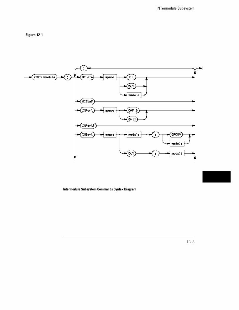
Figure 12-1
Intermodule Subsystem Commands Syntax Diagram
INTermodule Subsystem
12–3

Figure 12-1
Intermodule Subsystem Commands Syntax Diagram (Continued)
INTermodule Subsystem
12–4

Table 12-1 INTermodule Parameter Values
Parameter Value
module An integer, 1 to 10 (3 through 10 unused)
index An integer, 1 to 10 (3 through 10 unused)
setting A numeric, – 1.0 to 1.0 in seconds.
:INTermodule
Selector :INTermodule
The INTermodule selector specifies INTermodule as the subsystem thecommands or queries following will refer to. Because the INTermodulecommand is a root level command, it will normally appear as the first elementof a compound header.
Example OUTPUT XXX;":INTERMODULE:HTIME?"
DELete
Command :DELete {ALL|OUT|<module>}
The DELete command is used to delete a module, PORT OUT, or an entireintermodule tree. The <module> parameter sent with the delete commandrefers to the slot location of the module. The logic analyzer is slot 1 and theoscilloscope is slot 2.
<module> An integer, 1 through 10 (3 through 10 unused)
Example OUTPUT XXX;":INTERMODULE:DELETE ALL"OUTPUT XXX;":INTERMODULE:DELETE 1"
INTermodule Subsystem:INTermodule
12–5

HTIMe
Query :HTIMe?
The HTIMe query returns a value representing the internal hardware skew inthe Intermodule configuration. If there is no internal skew, or if intermodulebus is not configured, 9.9E37 is returned.
The internal hardware skew is only a display adjustment for time-correlatedwaveforms. The value returned is the average propagation delay of the triggerlines through the intermodule bus circuitry. The value is for reference onlybecause the value returned by TTIMe includes the internal hardware skewrepresented by HTIMe.
Returned Format [:INTermodule:HTIMe]<value_1>,<value_2>,<value_3>,<value_4>,<value_5><NL>
<value_1> Skew for logic analyzer (real number)
<value_2> Skew for oscilloscope (real number)
Example OUTPUT XXX;":INTERMODULE:HTIME?"
INPort
Command :INPort {{ON|1}|{OFF|0}}
The INPort command causes intermodule acquisitions to be armed from theInput port.
Example OUTPUT XXX;":INTERMODULE:INPORT ON"
INTermodule SubsystemHTIMe
12–6

Query :INPort?
The INPort query returns the current setting.Returned Format [:INTermodule:INPort] {1|0}<NL>
Example OUTPUT XXX;":INTERMODULE:INPORT?"
INSert
Command :INSert {<module>|OUT},{GROUP|<module>}
The INSert command adds PORT OUT to the Intermodule configuration. Thefirst parameter selects the logic analyzer or PORT OUT to be added to theintermodule configuration, and the second parameter tells the instrumentwhere the logic analyzer or PORT OUT will be located. A "1" corresponds tothe slot location of the logic analyzer, and a "2" corresponds to the slotlocation of the oscilloscope.
<module> An integer, 1 through 10 (3 through 10 unused)
Examples OUTPUT XXX;":INTERMODULE:INSERT 1,GROUP"OUTPUT XXX;":INTERMODULE:INSERT 2,GROUP"OUTPUT XXX;":INTERMODULE:INSERT OUT,2"
INTermodule SubsystemINSert
12–7

SKEW<N>
Command :SKEW<N> <setting>
The SKEW command sets the skew value for a module. The <N> index valueis the module number (1 corresponds to the logic analyzer, 2 corresponds tothe oscilloscope, and 3 through 10 unused). The <setting> parameter is theskew setting (– 1.0 to 1.0) in seconds.
<N> An integer, 1 through 10 (3 through 10 unused)
<setting> A real number from –1.0 to 1.0 seconds
Example OUTPUT XXX;":INTERMODULE:SKEW1 3.0E-9"
Query :SKEW<N>?
The query returns the user defined skew setting.Returned Format [INTermodule:SKEW<N>] <setting><NL>
Example OUTPUT XXX;":INTERMODULE:SKEW1?"
INTermodule SubsystemSKEW<N>
12–8

TREE
Command :TREE <module>,<module>
The TREE command allows an intermodule setup to be specified in onecommand. The first parameter is the intermodule arm value for module A(logic analyzer). The second parameter corresponds to the intermodule armvalue for PORT OUT. A –1 means the module is not in the intermodule tree,a 0 value means the module is armed from the Intermodule run button(Group run), and a positive value indicates the module is being armed byanother module with the slot location 1 to 10. A 1 corresponds to the slotlocation of the module A (logic analyzer, 2 corresponds to the slot location ofthe module B (oscilloscope) and 3 through 10 are unused.
<module> An integer, −1 through 10 (3 through 10 unused)
Example OUTPUT XXX;":INTERMODULE:TREE 0,-1,-1,-1,1"
Query :TREE?
The TREE? query returns a string that represents the intermodule tree. A −1means the module is not in the intermodule tree, a 0 value means the moduleis armed from the Intermodule run button (Group run), and a positive valueindicates the module is being armed by another module with the slot location1 to 10. A 1 corresponds to the slot location of the module A (logic analyzer)and 2 through 10 are unused.
Returned Format [INTermodule:TREE]<module_1>,<module_2>,<module_3>,<module_4>,<module_5><NL>
Example OUTPUT XXX;":INTERMODULE:TREE?"
INTermodule SubsystemTREE
12–9
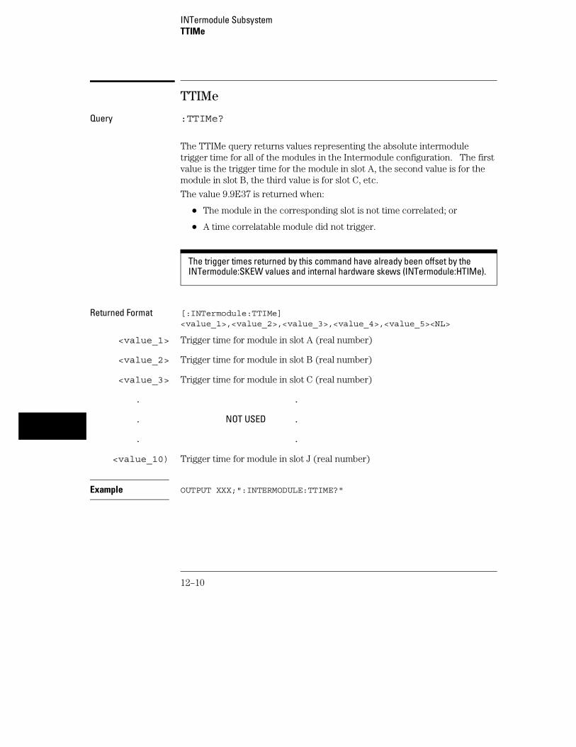
TTIMe
Query :TTIMe?
The TTIMe query returns values representing the absolute intermoduletrigger time for all of the modules in the Intermodule configuration. The firstvalue is the trigger time for the module in slot A, the second value is for themodule in slot B, the third value is for slot C, etc.
The value 9.9E37 is returned when:
• The module in the corresponding slot is not time correlated; or
• A time correlatable module did not trigger.
The trigger times returned by this command have already been offset by theINTermodule:SKEW values and internal hardware skews (INTermodule:HTIMe).
Returned Format [:INTermodule:TTIMe]<value_1>,<value_2>,<value_3>,<value_4>,<value_5><NL>
<value_1> Trigger time for module in slot A (real number)
<value_2> Trigger time for module in slot B (real number)
<value_3> Trigger time for module in slot C (real number)
. .
. NOT USED .
. .
<value_10) Trigger time for module in slot J (real number)
Example OUTPUT XXX;":INTERMODULE:TTIME?"
INTermodule SubsystemTTIMe
12–10

Part 3
Logic Analyzer Commands


13
MACHine Subsystem

Introduction
The MACHine subsystem contains the commands that control themachine level of operation of the logic analyzer. The functions ofthree of these commands reside in the State/Timing Configurationmenu. These commands are:
• ASSign
• NAME
• TYPE
Even though the functions of the following commands reside in theTrace menu they are at the machine level of the command tree andare therefore located in the MACHine subsystem. These commandsare:
• ARM
• LEVelarm
• REName
• RESource
13–2

Figure 13-1
Machine Subsystem Syntax Diagram
MACHine Subsystem
13–3

Table 13-1 Machine Parameter Values
Parameter Values
arm_source {RUN|INTermodule|MACHine{1|2}}
pod_list {NONE|<pod num>[,<pod num>]...}
pod_num {1|2|3|4|5|6|7|8}
arm_level An integer from 1 to 11 representing sequence level
machine_name A string of up to 10 alphanumeric characters
res_id <state_terms> for state analyzer or{<state_terms>|GLEDge{1|2}} for timing analyzer
new_text A string of up to 8 alphanumeric characters
state_terms {A|B|C|D|E|F|G|H|I|J|RANGE{1|2}|TIMER{1|2}}
res_terms {<res id>[,<res id>]...}
MACHine
Selector :MACHine<N>
The MACHine <N> selector specifies which of the two analyzers (machines)available in the 1660-series logic analyzer the commands or queries followingwill refer to. Because the MACHine<N> command is a root level command, itwill normally appear as the first element of a compound header.
<N> {1|2} (the machine number)
Example OUTPUT XXX; ":MACHINE1:NAME ’TIMING’"
MACHine SubsystemMACHine
13–4
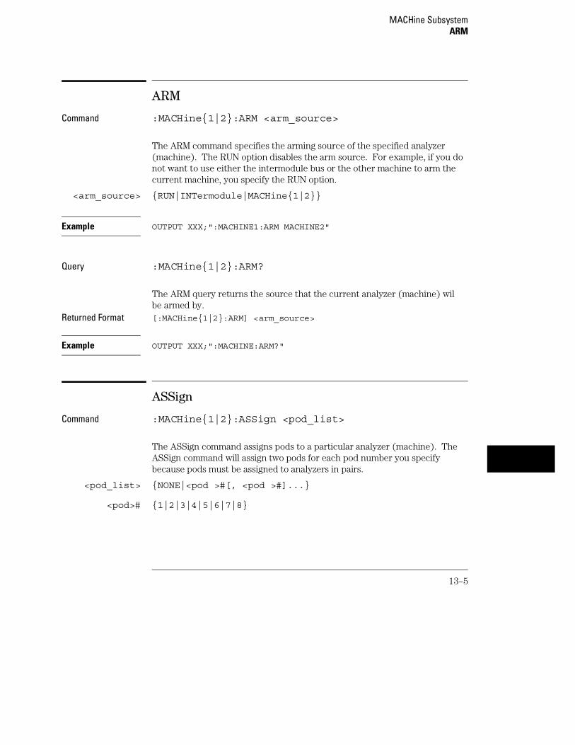
ARM
Command :MACHine{1|2}:ARM <arm_source>
The ARM command specifies the arming source of the specified analyzer(machine). The RUN option disables the arm source. For example, if you donot want to use either the intermodule bus or the other machine to arm thecurrent machine, you specify the RUN option.
<arm_source> {RUN|INTermodule|MACHine{1|2}}
Example OUTPUT XXX;":MACHINE1:ARM MACHINE2"
Query :MACHine{1|2}:ARM?
The ARM query returns the source that the current analyzer (machine) wilbe armed by.
Returned Format [:MACHine{1|2}:ARM] <arm_source>
Example OUTPUT XXX;":MACHINE:ARM?"
ASSign
Command :MACHine{1|2}:ASSign <pod_list>
The ASSign command assigns pods to a particular analyzer (machine). TheASSign command will assign two pods for each pod number you specifybecause pods must be assigned to analyzers in pairs.
<pod_list> {NONE|<pod >#[, <pod >#]...}
<pod># {1|2|3|4|5|6|7|8}
MACHine SubsystemARM
13–5

Example OUTPUT XXX;":MACHINE1:ASSIGN 5, 2, 1"
Query :MACHine{1|2}:ASSign?
The ASSign query returns which pods are assigned to the current analyzer(machine).
Returned Format [:MACHine{1|2}:ASSign] <pod_list><NL>
<pod_list> {NONE|<pod >#[, <pod >#]...}
<pod># {1|2|3|4|5|6|7|8}
Example OUTPUT XXX;":MACHINE1:ASSIGN?"
LEVelarm
Command :MACHine{1|2}:LEVelarm <arm_level>
The LEVelarm command allows you to specify the sequence level for aspecified machine that will be armed by the Intermodule Bus or the othermachine. This command is only valid if the specified machine is on and thearming source is not set to RUN with the ARM command.
<arm_level> An integer from 1 to the maximum number of levels specified in theappropriate trigger menu.
Example OUTPUT XXX;":MACHINE1:LEVELARM 2"
Query :MACHine{1|2}:LEVelarm?
The LEVelarm query returns the current sequence level receiving the armingfor a specified machine.
MACHine SubsystemLEVelarm
13–6

Returned Format: [:MACHine{1|2}:LEVelarm] <arm_level><NL>
<arm_level> An integer from 1 to 11 representing sequence level
Example OUTPUT XXX;":MACHINE1:LEVELARM?"
NAME
Command :MACHine{1|2}:NAME <machine_name>
The NAME command allows you to assign a name of up to 10 characters to aparticular analyzer (machine) for easier identification.
<machine_name> A string of up to 10 alphanumeric characters
Example OUTPUT XXX;":MACHINE1:NAME ’DRAMTEST’"
Query :MACHine{1|2}:NAME?
The NAME query returns the current analyzer name as an ASCII string.Returned Format [:MACHine{1|2}:NAME] <machine_name><NL>
<machine_name> A string of up to 10 alphanumeric characters
Example OUTPUT XXX;":MACHINE1:NAME?"
MACHine SubsystemNAME
13–7

REName
Command :MACHine{1|2}:REName {<res_id>, <new_text> |DEFault}
The REName command allows you to assign a specific name of up to eightcharacters to terms A through J, Range 1 and 2, and Timer 1 and 2 in thestate analyzer. In the timing analyzer, GLEDge (glitch/edge) 1 and 2 can berenamed in addition to the terms available in the state analyzer. TheDEFault option sets all resource term names to the default names assignedwhen turning on the instrument.
<res_id> <state_terms> for state analyzeror{<state_terms>|GLEDge{1|2}} for timing analyzer
<new_text> A string of up to 8 alphanumeric characters
Example OUTPUT XXX;":MACHINE1:RENAME A,’DATA’"
Query :MACHine{1|2}:RENAME? <res_id>
The REName query returns the current names for specified terms assignedto the specified analyzer.
Returned Format [:MACHine{1|2}:RENAME] <res_id>,<new_text><NL>
<res_id> <state_terms> for state analyzeror{<state_terms>|GLEDge{1|2}} for timing analyzer
<new_text> A string of up to 8 alphanumeric characters
Example OUTPUT XXX;":MACHINE1:RENAME? D"
MACHine SubsystemREName
13–8

RESource
Command :MACHine{1|2}:RESource <res_terms>
The RESource command allows you to assign resource terms A through J,Range 1 and 2, and Timer 1 and 2 to a particular analyzer (machine 1 or 2).
In the timing analyzer only, two additional resource terms are available. Theseterms are GLEDge (Glitch/Edge) 1 and 2. These terms will always be assigned tothe the machine that is configured as the timing analyzer.
<res_terms> {A|B|C|D|E|F|G|H|I|J|TIMer1|TIMer2|RANGe1|RANGe2}
Example OUTPUT XXX;":MACHINE1:RESOURCE A,C,RANGE1"
Query :MACHine{1|2}:RESOURCE?
The RESource query returns the current resource terms assigned to thespecified analyzer.
Returned Format [:MACHine{1|2}:RESOURCE] <res_terms>[,<res_terms>,...]<NL>
<res_terms> {A|B|C|D|E|F|G|H|I|J|TIMer1|TIMer2|RANGe1|RANGe2}
Example OUTPUT XXX;":MACHINE1:RESOURCE?"
MACHine SubsystemRESource
13–9

TYPE
Command :MACHine{1|2}:TYPE <analyzer_type>
The TYPE command specifies what type a specified analyzer (machine) willbe. The analyzer types are state or timing. The TYPE command also allowsyou to turn off a particular machine.
Only one timing analyzer can be specified at a time.
<analyzer_type> {OFF|STATe|TIMing}
Example OUTPUT XXX;":MACHINE1:TYPE STATE"
Query :MACHine{1|2}:TYPE?
The TYPE query returns the current analyzer type for the specified analyzer.Returned Format [:MACHine{1|2}:TYPE] <analyzer_type><NL>
<analyzer_type> {OFF|STATe|TIMing}
Example OUTPUT XXX;":MACHINE1:TYPE?"
MACHine SubsystemTYPE
13–10

14
WLISt Subsystem

Introduction
The WLISt subsystem contains the commands available for theTiming/State mixed mode display. The X and O markers can only beplaced on the waveforms in the waveform portion of the Timing/Statemixed mode display. The XSTate and OSTate queries return whatstates the X and O markers are on. Because the markers can only beplaced on the timing waveforms, the queries return what state (stateacquisition memory location) the marked pattern is stored in.
In order to have mixed mode, one machine must be a state analyzer with timetagging on (use MACHine<N>:STRigger:TAG TIME).
The WLISt subsystem commands are:
• DELay
• INSert
• LINE
• OSTate
• OTIMe
• RANGe
• REMove
• XOTime
• XSTate
• XTIMe
14–2

Figure 14-1
WLISt Subsystem Syntax Diagram
WLISt Subsystem
14–3

Table 14-1 WLISt Parameter Values
Parameter Value
delay_value Real number between −2500 s and +2500 s
module_spec {1|2|3|4|5|6|7|8|9|10} (slot where timing card isinstalled, 2 through 10 unused)
bit_id An integer from 0 to 31
label_name String of up to 6 alphanumeric characters
line_num_mid_screen An integer from −8191 to +8191
waveform String containing <acquisition spec>{1|2}
time_value Real number
time_range Real number between 10 ns and 10 ks
WLISt
Selector :WLISt
The WLISt (Waveforms/LISting) selector is used as a part of a compoundheader to access the settings normally found in the Mixed Mode menu.Because the WLISt command is a root level command, it will always appearas the first element of a compound header.
The WLISt subsystem is only available when one or more state analyzers, withtime tagging on, are specified.
Example OUTPUT XXX;":WLIST:XTIME 40.0E−6"
WLISt SubsystemWLISt
14–4

DELay
Command :MACHine{1|2}:WLISt:DELay <delay_value>
The DELay command specifies the amount of time between the timingtrigger and the horizontal center of the the timing waveform display. Theallowable values for delay are −2500 s to +2500 s.
<delay_value> Real number between −2500 s and +2500 s
Example OUTPUT XXX;":MACHINE1:WLIST:DELAY 100E−6"
Query :MACHine{1|2}:WLISt:DELay?
The DELay query returns the current time offset (delay) value from thetrigger.
Returned Format [:MACHine{1|2}:WLISt:DELay] <time_value><NL>
<delay_value> Real number between −2500 s and +2500 s
Example OUTPUT XXX;":MACHINE1:WLIST:DELAY?"
WLISt SubsystemDELay
14–5
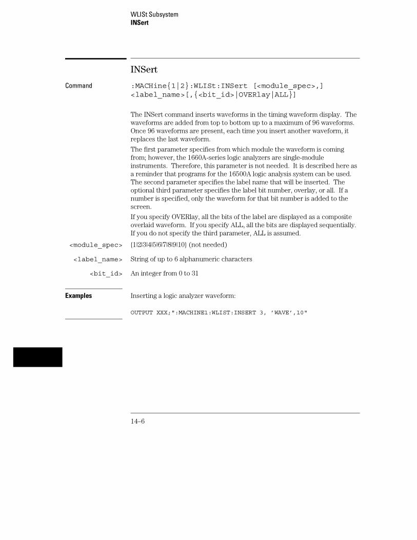
INSert
Command :MACHine{1|2}:WLISt:INSert [<module_spec>,]<label_name>[,{<bit_id>|OVERlay|ALL}]
The INSert command inserts waveforms in the timing waveform display. Thewaveforms are added from top to bottom up to a maximum of 96 waveforms.Once 96 waveforms are present, each time you insert another waveform, itreplaces the last waveform.
The first parameter specifies from which module the waveform is comingfrom; however, the 1660A-series logic analyzers are single-moduleinstruments. Therefore, this parameter is not needed. It is described here asa reminder that programs for the 16500A logic analysis system can be used.The second parameter specifies the label name that will be inserted. Theoptional third parameter specifies the label bit number, overlay, or all. If anumber is specified, only the waveform for that bit number is added to thescreen.
If you specify OVERlay, all the bits of the label are displayed as a compositeoverlaid waveform. If you specify ALL, all the bits are displayed sequentially.If you do not specify the third parameter, ALL is assumed.
<module_spec> {1|2|3|4|5|6|7|8|9|10} (not needed)
<label_name> String of up to 6 alphanumeric characters
<bit_id> An integer from 0 to 31
Examples Inserting a logic analyzer waveform:
OUTPUT XXX;":MACHINE1:WLIST:INSERT 3, ’WAVE’,10"
WLISt SubsystemINSert
14–6
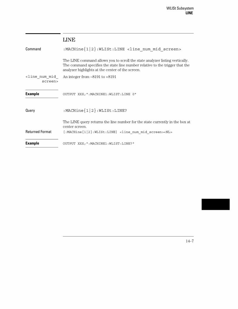
LINE
Command :MACHine{1|2}:WLISt:LINE <line_num_mid_screen>
The LINE command allows you to scroll the state analyzer listing vertically.The command specifies the state line number relative to the trigger that theanalyzer highlights at the center of the screen.
<line_num_mid_screen>
An integer from −8191 to +8191
Example OUTPUT XXX;":MACHINE1:WLIST:LINE 0"
Query :MACHine{1|2}:WLISt:LINE?
The LINE query returns the line number for the state currently in the box atcenter screen.
Returned Format [:MACHine{1|2}:WLISt:LINE] <line_num_mid_screen><NL>
Example OUTPUT XXX;":MACHINE1:WLIST:LINE?"
WLISt SubsystemLINE
14–7

OSTate
Query :WLISt:OSTate?
The OSTate query returns the state where the O Marker is positioned. If datais not valid, the query returns 32767.
Returned Format [:WLISt:OSTate] <state_num><NL>
<state_num> An integer from −8191 to +8191
Example OUTPUT XXX;":WLIST:OSTATE?"
OTIMe
Command :WLISt:OTIMe <time_value>
The OTIMe command positions the O Marker on the timing waveforms in themixed mode display. If the data is not valid, the command performs noaction.
<time_value> A real number
Example OUTPUT XXX;":WLIST:OTIME 40.0E−6"
WLISt SubsystemOSTate
14–8

Query :WLISt:OTIMe?
The OTIMe query returns the O Marker position in time. If data is not valid,the query returns 9.9E37.
Returned Format [:WLISt:OTIMe] <time_value><NL>
<time_value> A real number
Example OUTPUT XXX;":WLIST:OTIME?"
RANGe
Command :MACHine{1|2}:WLISt:RANGe <time_value>
The RANGe command specifies the full-screen time in the timing waveformmenu. It is equivalent to ten times the seconds per division setting on thedisplay. The allowable values for RANGe are from 10 ns to 10 ks.
<time_value> A real number between 10 ns and 10 ks
Example OUTPUT XXX;":MACHINE1:WLIST:RANGE 100E−9"
Query :MACHine{1|2}:WLISt:RANGe?
The RANGe query returns the current full-screen time.Returned Format [:MACHine{1|2}:WLISt:RANGe] <time_value><NL>
<time_value> A real number between 10 ns and 10 ks
Example OUTPUT XXX;":MACHINE1:WLIST:RANGE?"
WLISt SubsystemRANGe
14–9
REMove
Command :MACHine{1|2}:WLISt:REMove
The REMove command deletes all waveforms from the display.
Example OUTPUT XXX;":MACHINE1:WLIST:REMOVE"
XOTime
Query :MACHine{1|2}:WLISt:XOTime?
The XOTime query returns the time from the X marker to the O marker. Ifdata is not valid, the query returns 9.9E37.
Returned Format [:MACHine{1|2}:WLISt:XOTime] <time_value><NL>
<time_value> A real number
Example OUTPUT XXX;":MACHINE1:WLIST:XOTIME?"
WLISt SubsystemREMove
14–10
XSTate
Query :WLISt:XSTate?
The XSTate query returns the state where the X Marker is positioned. If datais not valid, the query returns 32767.
Returned Format [:WLISt:XSTate] <state_num><NL>
<state_num> An integer
Example OUTPUT XXX;":WLIST:XSTATE?"
XTIMe
Command :WLISt:XTIMe <time_value>
The XTIMe command positions the X Marker on the timing waveforms in themixed mode display. If the data is not valid, the command performs noaction.
<time_value> A real number
Example OUTPUT XXX;":WLIST:XTIME 40.0E−6"
WLISt SubsystemXSTate
14–11

Query :WLISt:XTIMe?
The XTIMe query returns the X Marker position in time. If data is not valid,the query returns 9.9E37.
Returned Format [:WLISt:XTIMe] <time_value><NL>
<time_value> A real number
Example OUTPUT XXX;":WLIST:XTIME?"
WLISt SubsystemXTIMe
14–12

15
SFORmat Subsystem

Introduction
The SFORmat subsystem contains the commands available for theState Format menu in the 1660A-series logic analyzers. Thesecommands are:
• CLOCk
• LABel
• MASTer
• MODE
• MOPQual
• MQUal
• REMove
• SETHold
• SLAVe
• SOPQual
• SQUal
• THReshold
15–2

Figure 15-1
SFORmat Subsystem Syntax Diagram
SFORmat Subsystem
15–3
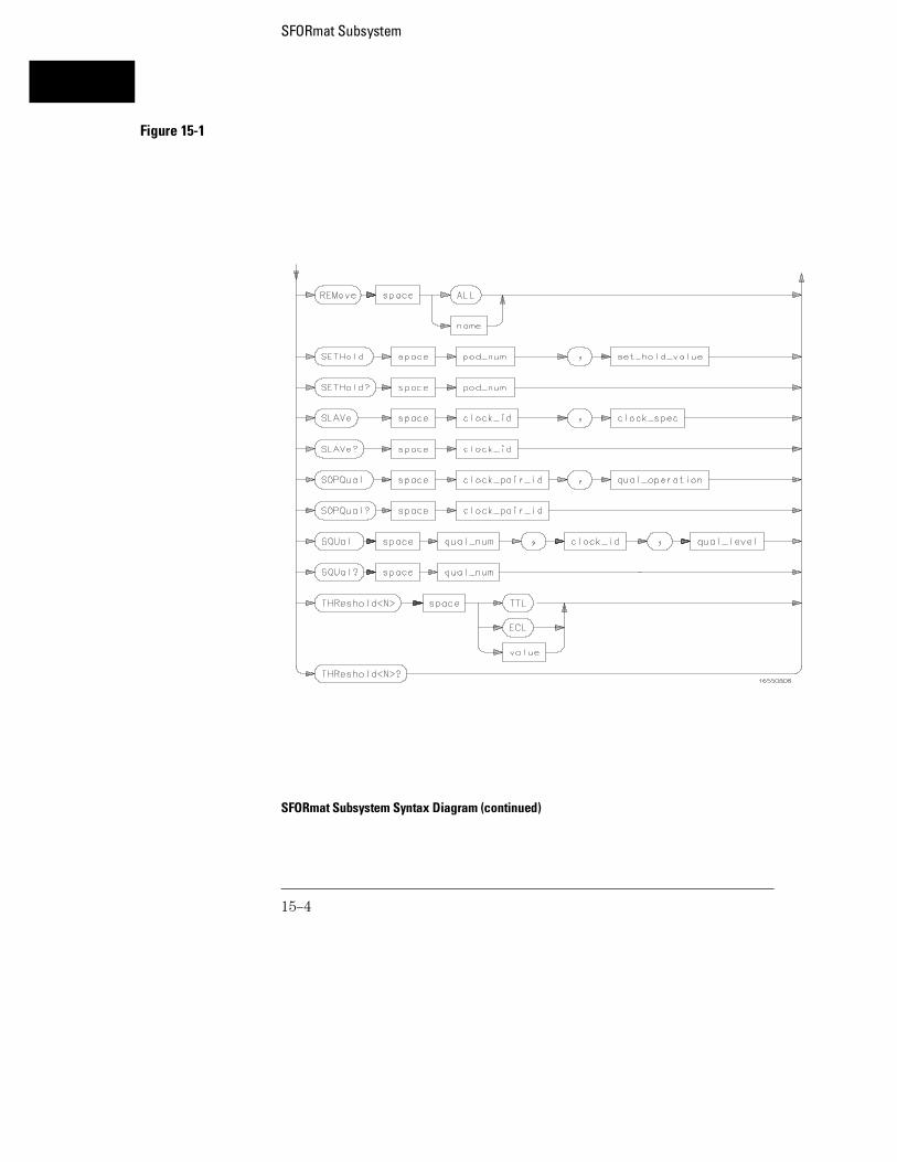
Figure 15-1
SFORmat Subsystem Syntax Diagram (continued)
SFORmat Subsystem
15–4

Table 15-1 SFORmat Parameter Values
Parameter Values
<N> {{1|2}|{3|4|5|6}|{7|8}}
label_name String of up to 6 alphanumeric characters
polarity {POSitive|NEGative}
clock_bits Format (integer from 0 to 63) for a clock (clocks are assignedin decreasing order)
upper_bits Format (integer from 0 to 65535) for a pod (pods are assignedin decreasing order)
lower_bits Format (integer from 0 to 65535) for a pod (pods are assignedin decreasing order)
clock_id {J|K|L|M|N|P}
clock_spec {OFF|RISing|FALLing|BOTH}
clock_pair_id {1|2}
qual_operation {AND|OR}
qual_num {1|2|3|4}
qual_level {OFF|LOW|HIGH}
pod_num {1|2|3|4|5|6|7|8}
set_hold_value {0|1|2|3|4|5|6|7|8|9}
value voltage (real number) −6.00 to +6.00
SFORmat Subsystem
15–5

SFORmat
Selector :MACHine{1|2}:SFORmat
The SFORmat (State Format) selector is used as a part of a compoundheader to access the settings in the State Format menu. It always follows theMACHine selector because it selects a branch directly below the MACHinelevel in the command tree.
Example OUTPUT XXX;":MACHINE2:SFORMAT:MASTER J, RISING"
CLOCk
Command :MACHine{1|2}:SFORmat:CLOCk<N> <clock_mode>
The CLOCk command selects the clocking mode for a given pod when thepod is assigned to the state analyzer. When the MASTer option is specified,the pod will sample all 16 channels on the master clock. When the SLAVeoption is specified, the pod will sample all 16 channels on the slaveclock. When the DEMultiplex option is specified, only one pod of a pod paircan acquire data. The 16 bits of the selected pod will be clocked by thedemultiplex master for labels with bits assigned under the Master pod. Thesame 16 bits will be clocked by the demultiplex slave for labels with bitsassigned under the Slave pod. The master clock always follows the slaveclock when both are used.
<N> {{1|2}| {3|4}|{5|6}|{7|8}} 1 through 8 for the HP 1660A, 1 through6 for the HP 1661A, 1 through 4 for the HP 1662A, and 1 through 2 for the HP1663A.
<clock_mode> {MASTer|SLAVe|DEMultiplex}
Example OUTPUT XXX;":MACHINE1:SFORMAT:CLOCK2 MASTER"
SFORmat SubsystemSFORmat
15–6

Query :MACHine{1|2}:SFORmat:CLOCk<N>?
The CLOCk query returns the current clocking mode for a given pod.Returned Format [:MACHine{1|2}:SFORmat:CLOCK<N>] <clock_mode><NL>
Example OUTPUT XXX; ":MACHINE1:SFORMAT:CLOCK2?"
LABel
Command :MACHine{1|2}:SFORmat:LABel <name>,[<polarity>,<clock_bits>, <upper_bits>, <lower_bits>[,<upper_bits>,<lower_bits>]...]
The LABel command allows you to specify polarity and assign channels tonew or existing labels. If the specified label name does not match an existinglabel name, a new label will be created.
The order of the pod-specification parameters is significant. The first onelisted will match the highest numbered pod assigned to the machine you’reusing. Each pod specification after that is assigned to the next highestnumbered pod. This way they match the left-to-right descending order of thepods you see on the Format display. Not including enough pod specificationsresults in the lowest numbered pod(s) being assigned a value of zero (allchannels excluded). If you include more pod specifications than there arepods for that machine, the extra ones will be ignored. However, an error isreported anytime when more than 13 pod specifications are listed.
The polarity can be specified at any point after the label name.
Because pods contain 16 channels, the format value for a pod must bebetween 0 and 65535 (216−1). When giving the pod assignment in binary(base 2), each bit will correspond to a single channel. A "1" in a bit positionmeans the associated channel in that pod is assigned to that pod and bit. A"0" in a bit position means the associated channel in that pod is excludedfrom the label. For example, assigning #B1111001100 is equivalent toentering "......****..**.." from the front panel.
A label can not have a total of more than 32 channels assigned to it.
<name> String of up to 6 alphanumeric characters
SFORmat SubsystemLABel
15–7

<polarity> {POSitive|NEGative}
<clock_bits> Format (integer from 0 to 63) for a clock (clocks are assigned in decreasingorder)
<upper_bits> Format (integer from 0 to 65535) for a pod (pods are assigned in decreasingorder)
<lower_bits> Format (integer from 0 to 65535) for a pod (pods are assigned in decreasingorder)
Examples OUTPUT XXX;":MACHINE2:SFORMAT:LABEL ’STAT’, POSITIVE,0,127,40312"OUTPUT XXX;":MACHINE2:SFORMAT:LABEL ’SIG 1’, #B11,#B0000000011111111,#B0000000000000000 "
Query :MACHine{1|2}:SFORmat:LABel? <name>
The LABel query returns the current specification for the selected (by name)label. If the label does not exist, nothing is returned. The polarity is alwaysreturned as the first parameter. Numbers are always returned in decimalformat.
Returned Format [:MACHine{1|2}:SFORmat:LABel] <name>,<polarity>[, <clock_bits>, <upper_bits>, <lower_bits>]<NL>
Example OUTPUT XXX;":MACHINE2:SFORMAT:LABEL? ’DATA’"
SFORmat SubsystemLABel
15–8

MASTer
Command Syntax: :MACHine{1|2}:SFORmat:MASTer <clock_id>,<clock_spec>
The MASTer clock command allows you to specify a master clock for a givenmachine. The master clock is used in all clocking modes (Master, Slave, andDemultiplexed). Each command deals with only one clock (J,K,L,M,N,P);therefore, a complete clock specification requires six commands, one foreach clock. Edge specifications (RISing, FALLing, or BOTH) are ORed.
At least one clock edge must be specified.
<clock_id> {J|K|L|M|N|P}
<clock_spec> {OFF|RISing|FALLing|BOTH}
Example OUTPUT XXX;":MACHINE2:SFORMAT:MASTER J, RISING"
Query :MACHine{1|2}:SFORmat:MASTer? <clock_id>
The MASTer query returns the clock specification for the specified clock.Returned Format [:MACHine{1|2}:SFORmat:MASTer]<clock_id>,<clock_spec><NL>
Example OUTPUT XXX;":MACHINE2:SFORMAT:MASTER? <clock_id>"
SFORmat SubsystemMASTer
15–9

MODE
Command :MACHine{1|2}:SFORmat:MODE <acq_mode>
The MODE command allows you to select the acquistion mode of the stateanalyzer. The modes are either full-channel with 4 Kbit of memory depth perchannel or half-channel with 8 Kbit of memory depth per channel.
<acq_mode> {FULL|DEEPmemory}
Example OUTPUT XXX;":MACHine1:SFORMAT:MODE FULL"
Query :MACHine{1|2}:SFORmat:MODE?
The MODE query returns the current acquistion mode.Returned Format [:MACHine{1|2}:SFORmat:MODE] <acq_mode><NL>
Example OUTPUT XXX;":MACHINE1:SFORMAT:MODE?"
SFORmat SubsystemMODE
15–10

MOPQual
Command :MACHine{1|2}:SFORmat:MOPQual <clock_pair_id>,<qual_operation>
The MOPQual (master operation qualifier) command allows you to specifyeither the AND or the OR operation between master clock qualifier pair 1 and2, or between master clock qualifier pair 3 and 4. For example, you canspecify a master clock operation qualifer 1 AND 2.
<clock_pair_id> {1|2}
<qual_operation>
{AND|OR}
Example OUTPUT XXX;":MACHINE1:SFORMAT:MOPQUAL 1,AND"
Query :MACHine{1|2}:SFORmat:MOPQUal? <clock_pair_id>
The MOPQual query returns the operation qualifier specified for the masterclock.
Returned Format: [:MACHine{1|2}:SFORmat:MOPQUal <clock_pair_id>]<qual_operation><NL>
Example OUTPUT XXX;":MACHine1:SFORMAT:MOPQUAL? 1"
SFORmat SubsystemMOPQual
15–11

MQUal
Command :MACHine{1|2}:SFORmat:MQUal<qual_num>,<clock_id>,<qual_level>
The MQUal (master qualifier) command allows you to specify the levelqualifier for the master clock.
<qual_num> {{1|2}|{3|4}} 1 through 4 for HP 1660A, HP 1661A, HP 1662A; or, 1 or 2for HP 1663A.
<clock_id> {J|K|L|M|N|P}
<qual_level> {OFF|LOW|HIGH}
Example OUTPUT XXX;":MACHINE2:SFORMAT:MQUAL 1,J,LOW"
Query :MACHine{1|2}:SFORmat:MQUal? <qual num>
The MQUal query returns the qualifier specified for the master clock.Returned Format [:MACHine{1|2}:SFORmat:MQUal] <qual_level><NL>
Example OUTPUT XXX;":MACHINE2:SFORMAT:MQUAL? 1"
SFORmat SubsystemMQUal
15–12

REMove
Command :MACHine{1|2}:SFORmat:REMove {<name>|ALL}
The REMove command allows you to delete all labels or any one label for agiven machine.
<name> String of up to 6 alphanumeric characters
Examples OUTPUT XXX;":MACHINE2:SFORMAT:REMOVE ’A’"OUTPUT XXX;":MACHINE2:SFORMAT:REMOVE ALL"
SETHold
Command :MACHine{1|2}:SFORmat:SETHold <pod_num>,<set_hold_value>
The SETHold (setup/hold) command allows you to set the setup and holdspecification for the state analyzer.
Even though the command requires integers to specify the setup and hold, thequery returns the current settings in a string. For example, if you send theinteger 0 for the setup and hold value, the query will return 3.5/0.0 ns as anASCII string when you have one clock and one edge specified.
SFORmat SubsystemREMove
15–13

<pod_num> {{1|2}|{3|4}|{5|6}|{7|8}} 1 through 8 for the HP 1660A, 1 through6 for the HP 1661A, 1 through 4 for the HP 1662A, and 1 through 2 for the HP1663A.
<set_hold_value>
An integer {0|1|2|3|4|5|6|7|8|9} representing the setup and holdvalues in table 15-2.
Table 15-2 Setup and hold values
For one clock and oneedge
For one clock and bothedges
For multiple clocks
0 = 3.5/0.0 ns 0 = 4.0/0.0 0 = 4.5/0.0
1 = 3.0/0.5 ns 1 = 3.5/0.5 1 = 4.0/0.5
2 = 2.5/1.0 ns 2 = 3.0/1.0 2 = 3.5/1.0
3 = 2.0/1.5 ns 3 = 2.5/1.5 3 = 3.0/1.5
4 = 1.5/2.0 ns 4 = 2.0/2.0 4 = 2.5/2.0
5 = 1.0/2.5 ns 5 = 1.5/2.5 5 = 2.0/2.5
6 = 0.5/3.0 ns 6 = 1.0/3.0 6 = 1.5/3.0
7 = 0.0/3.5 ns 7 = 0.5/3.5 7 = 1.0/3.5
N/A 8 = 0.0/4.0 8 = 0.5/4.0
N/A N/A 9 = 0.0/4.5
Example OUTPUT XXX;":MACHINE2:SFORMAT:SETHOLD 1,2"
Query :MACHine{1|2}:SFORMAT:SETHOLD? <pod_num>
The SETHold query returns the current setup and hold settings.Returned Format [:MACHine{1|2}:SFORmat:SETHold <pod_num>] <set_hold_value><NL>
Example OUTPUT XXX;":MACHINE2:SFORMAT:SETHOLD? 3"
SFORmat SubsystemSETHold
15–14

SLAVe
Command :MACHine{1|2}:SFORmat:SLAVe<clock_id>,<clock_spec>
The SLAVe clock command allows you to specify a slave clock for a givenmachine. The slave clock is only used in the Slave and Demultiplexedclocking modes. Each command deals with only one clock (J,K,L,M,N,P);therefore, a complete clock specification requires six commands, one foreach clock. Edge specifications (RISing, FALLing, or BOTH) are ORed.
When slave clock is being used at least one edge must be specified.
<clock_id> {J|K|L|M|N|P}
<clock_spec> {OFF|RISing|FALLing|BOTH}
Example OUTPUT XXX;":MACHINE2:SFORMAT:SLAVE J, RISING"
Query :MACHine{1|2}:SFORmat:SLAVe?<clock id>
The SLAVe query returns the clock specification for the specified clock.Returned Format [:MACHine{1|2}:SFORmat:SLAVe] <clock_id>,<clock_spec><NL>
Example OUTPUT XXX;":MACHINE2:SFORMAT:SLAVE? K"
SFORmat SubsystemSLAVe
15–15

SOPQual
Command :MACHine{1|2}:SFORmat:SOPQual <clock_pair_id>,<qual operation>
The SOPQual (slave operation qualifier) command allows you to specifyeither the AND or the OR operation between slave clock qualifier pair 1 and2, or between slave clock qualifier pair 3 and 4. For example you can specifya slave clock operation qualifer 1 AND 2.
<clock_pair_id> {1|2}
<qual_operation>
{AND|OR}
Example OUTPUT XXX;":MACHine2:SFORMAT:SOPQUAL 1,AND"
Query :MACHine{1|2}:SFORmat:SOPQual? <clock pair id>
The SOPQual query returns the operation qualifier specified for the slaveclock.
Returned Format [:MACHine{1|2}:SFORmat:SOPQual <clock_pair_id>]<qual_operation><NL>
Example OUTPUT XXX;":MACHiNE2:SFORMAT:SOPQUAL? 1"
SFORmat SubsystemSOPQual
15–16

SQUal
Command :MACHine{1|2}:SFORmat:SQUal <qual_num>,<clock_id>,<qual_level>
The SQUal (slave qualifier) command allows you to specify the level qualifierfor the slave clock.
<qual_num> {{1|2}|{3|4}} 1 through 4 for HP 1660A, HP 1661A, HP 1662A; or, 1 or 2for HP 1663A.
<clock_id> {J|K|L|M|N|P}
<qual_level> {OFF|LOW|HIGH}
Example OUTPUT XXX;":MACHINE2:SFORMAT:SQUAL 1,J,LOW"
Query :MACHine{1|2}:SFORmat:SQUal?<qual_num>
The SQUal query returns the qualifier specified for the slave clock.Returned Format [:MACHine{1|2}:SFORmat:SQUal] <clock_id>,<qual_level><NL>
Example OUTPUT XXX;":MACHINE2:SFORMAT:SQUAL? 1"
SFORmat SubsystemSQUal
15–17

THReshold
Command :MACHine{1|2}:SFORmat:THReshold<N>{TTL|ECL|<value>}
The THReshold command allows you to set the voltage threshold for a givenpod to ECL, TTL, or a specific voltage from −6.00 V to +6.00 V in 0.05 voltincrements.
<N> {{1|2}|{3|4}|{5|6}|{7|8}} 1 through 8 for the HP 1660A, 1 through6 for the HP 1661A, 1 through 4 for the HP 1662A, and 1 through 2 for the HP1663A.
<value> Voltage (real number) −6.00 to +6.00
TTL Default value of +1.6 V
ECL Default value of −1.3 V
Example OUTPUT XXX;":MACHINE1:SFORMAT:THRESHOLD1 4.0"
Query :MACHine{1|2}:SFORmat:THReshold<N>?
The THReshold query returns the current threshold for a given pod.Returned Format [:MACHine{1|2}:SFORmat:THReshold<N>] <value><NL>
Example OUTPUT XXX;":MACHINE1:SFORMAT:THRESHOLD4?"
SFORmat SubsystemTHReshold
15–18

16
STRigger (STRace) Subsystem

Introduction
The STRigger subsystem contains the commands available for theState Trigger menu in the 1660A-series logic analyzers. The StateTrigger subsystem will also accept the STRace Command as used inprevious 1650-series logic analyzers to eliminate the need to rewriteprograms containing STRace as the Command keyword. TheSTRigger subsystem commands are:
• ACQuisition
• BRANch
• CLEar
• FIND
• RANGe
• SEQuence
• STORe
• TAG
• TAKenbranch
• TCONtrol
• TERM
• TIMER
• TPOSition
16–2

Figure 16-1
STRigger Subsystem Syntax Diagram
STRigger (STRace) Subsystem
16–3

Figure 16-1 (continued)
STRigger Subsystem Syntax Diagram (continued)
STRigger (STRace) Subsystem
16–4

Figure 16-1 (continued)
STRigger Subsystem Suntax Diagram (continued)
STRigger (STRace) Subsystem
16–5

Table 16-1 STRigger Parameter Values
Parameter Values
branch_qualifier <qualifier>
to_lev_num integer from 1 to last level
proceed_qualifier <qualifier>
occurrence number from 1 to 1048575
label_name string of up to 6 alphanumeric characters
start_pattern "{#B{0|1} . . . |#Q{0|1|2|3|4|5|6|7} . . . |#H{0|1|2|3|4|5|6|7|8|9|A|B|C|D|E|F} . .. |{0|1|2|3|4|5|6|7|8|9} . . . }"
stop_pattern "{#B{0|1} . . . |#Q{0|1|2|3|4|5|6|7} . . . |#H{0|1|2|3|4|5|6|7|8|9|A|B|C|D|E|F} . .. |{0|1|2|3|4|5|6|7|8|9} . . . }"
num_of_levels integer from 2 to 12
lev_of_trig integer from 1 to (number of existing sequence levels − 1)
store_qualifier <qualifier>
state_tag_qualifier <qualifier>
timer_num {1|2}
timer_value 400 ns to 500 seconds
term_id {A|B|C|D|E|F|G|H|I|J}
pattern "{#B{0|1|X} . . . |#Q{0|1|2|3|4|5|6|7|x} . . . |#H{0|1|2|3|4|5|6|7|8|9|A|B|C|D|E|F|x}...|
{0|1|2|3|4|5|6|7|8|9} . . . }"
qualifier see "Qualifier" on page 16-7
post_value integer from 0 to 100 representing percentage
STRigger (STRace) Subsystem
16–6

Qualifier
The qualifier for the state trigger subsystem can be terms A through J, Timer1 and 2, and Range 1 and 2. In addition, qualifiers can be the NOT booleanfunction of terms, timers, and ranges. The qualifier can also be an expressionor combination of expressions as shown below and figure 16-2, "ComplexQualifier," on page 16-11.
The following parameters show how qualifiers are specified in all commandsof the STRigger subsystem that use <qualifier>.
<qualifier> {"ANYSTATE"|"NOSTATE"|"<expression>"}
<expression> {<expression1a>|<expression1b>|<expression1a> OR<expression1b>|<expression1a> AND <expression1b>}
<expression1a> {<expression1a_term>|(<expression1a_term>[ OR<expression1a_term>]* )|(<expression1a_term>[ AND<expression1a_term>]* )}
<expression1a_term>
{ <expression2a>|<expression2b>|<expression2c>|<expression2d>}
<expression1b> {<expression1b_term>|( <expression1b_term>[ OR<expression1b_term>]* )|(<expression1b_term>[ AND<expression1b_term>]* )}
<expression1b_term>
{<expression2e>|<expression2f>|<expression2g>|<expression2h>}
<expression2a> {<term3a>|<term3b>|(<term3a> <boolean_op> <term3b>)}
<expression2b> {<term3c>|<range3a>|(<term3c> <boolean_op> <range3a>)}
<expression2c> {<term3d>}
<expression2d> {<term3e>|<timer3a>|(<term3e> <boolean_op> <timer3a>)}
<expression2e> {<term3f>|<term3g>|(<term3f> <boolean_op> <term3g>)}
<expression2f> {<term3h>|<range3b>|(<term3h> <boolean_op> <range3b>)}
<expression2g> {<term3i>}
<expression2h> {<term3j>|<timer3b>|(<term3e> <boolean_op> <timer3b>)}
<boolean_op> {AND|NAND|OR|NOR|XOR|NXOR}
<term3a> {A|NOTA}
STRigger (STRace) SubsystemQualifier
16–7

<term3b> {B|NOTB}
<term3c> {C|NOTC}
<term3d> {D|NOTD}
<term3e> {E|NOTE}
<term3f> {F|NOTF}
<term3g> {G|NOTG}
<term3h> {H|NOTH}
<term3i> {I|NOTI}
<term3j> {J|NOTJ}
<range3a> {IN_RANGE1|OUT_RANGE1}
<range3b> {IN_RANGE2|OUT_RANGE2}
<timer3a> {TIMER1<|TIMER1>}
<timer3b> {TIMER2<|TIMER2>}
Qualifier Rules
The following rules apply to qualifiers:
• Qualifiers are quoted strings and, therefore, need quotes.
• Expressions are evaluated from left to right.
• Parenthesis are used to change the order evaluation and, therefore, areoptional.
• An expression must map into the combination logic presented in thecombination pop-up menu within the STRigger menu (see figure 16-2 onpage 16-12).
Examples ’A’’( A OR B )’’(( A OR B ) AND C )’’(( A OR B ) AND C AND IN_RANGE2 )’’(( A OR B ) AND ( C AND IN_RANGE1 ))’’IN_RANGE1 AND ( A OR B ) AND C’
STRigger (STRace) SubsystemQualifier
16–8
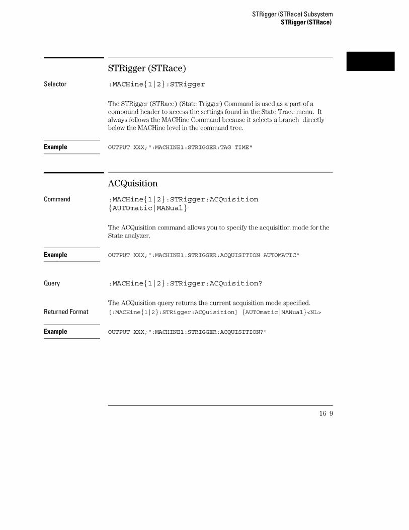
STRigger (STRace)
Selector :MACHine{1|2}:STRigger
The STRigger (STRace) (State Trigger) Command is used as a part of acompound header to access the settings found in the State Trace menu. Italways follows the MACHine Command because it selects a branch directlybelow the MACHine level in the command tree.
Example OUTPUT XXX;":MACHINE1:STRIGGER:TAG TIME"
ACQuisition
Command :MACHine{1|2}:STRigger:ACQuisition{AUTOmatic|MANual}
The ACQuisition command allows you to specify the acquisition mode for theState analyzer.
Example OUTPUT XXX;":MACHINE1:STRIGGER:ACQUISITION AUTOMATIC"
Query :MACHine{1|2}:STRigger:ACQuisition?
The ACQuisition query returns the current acquisition mode specified.Returned Format [:MACHine{1|2}:STRigger:ACQuisition] {AUTOmatic|MANual}<NL>
Example OUTPUT XXX;":MACHINE1:STRIGGER:ACQUISITION?"
STRigger (STRace) SubsystemSTRigger (STRace)
16–9

BRANch
Command :MACHine{1|2}:STRigger:BRANch<N><branch_qualifier>,<to_level_number>
The BRANch command defines the branch qualifier for a given sequencelevel. When this branch qualifier is matched, it will cause the sequencer tojump to the specified sequence level.
The terms used by the branch qualifier (A through J) are defined by theTERM command. The meaning of IN_RANGE and OUT_RANGE isdetermined by the RANGE command.
Within the limitations shown by the syntax definitions, complex expressionsmay be formed using the AND and OR operators. Expressions are limited towhat you could manually enter through the State Trigger menu. Regardingparentheses, the syntax definitions on the next page show only the requiredones. Additional parentheses are allowed as long as the meaning of theexpression is not changed. Figure 16-2 shows a complex expression as seenin the State Trigger menu.
Example The following statements are all correct and have the same meaning. Noticethat the conventional rules for precedence are not followed. The expressionsare evaluated from left to right.
OUTPUT XXX;":MACHINE1:STRIGGER:BRANCH1 ’C AND D OR F OR G’, 1"OUTPUT XXX;":MACHINE1:STRIGGER:BRANCH1 ’((C AND D) OR(F OR G))’, 1"OUTPUT XXX;":MACHINE1:STRIGGER:BRANCH1 ’F OR (C AND D) ORG’,1"
<N> An integer from 1 to <number_of_levels>
<to_level_number>
An integer from 1 to <number_of_levels>
<number_of_levels>
An integer from 2 to the number of existing sequence levels (maximum 12)
<branch_qualifier>
<qualifier> see "Qualifier" on page 16-7
STRigger (STRace) SubsystemBRANch
16–10

Examples OUTPUT XXX;":MACHINE1:STRIGGER:BRANCH1 ’ANYSTATE’, 3"OUTPUT XXX;":MACHINE2:STRIGGER:BRANCH2 ’A’, 7"OUTPUT XXX;":MACHINE1:STRIGGER:BRANCH3 ’((A OR B) OR NOTG)’,1"
Query :MACHine{1|2}:STRigger:BRANch<N>?
The BRANch query returns the current branch qualifier specification for agiven sequence level.
Returned Format [:MACHine{1|2}:STRigger:BRANch<N>] <branch_qualifier>,<to_level_num><NL>
Example OUTPUT XXX;":MACHINE1:STRIGGER:BRANCH3?"
Figure 16-2
Complex qualifier
Figure 16-2 is a front panel representation of the complex qualifier (a OR b)AND (g OR h).
STRigger (STRace) SubsystemBRANch
16–11

Example This example would be used to specify this complex qualifier.
OUTPUT XXX;":MACHINE1:STRIGGER:BRANCH1 ’((A OR B) AND(G OR H))’, 2"
Terms A through E, RANGE 1, and TIMER 1 must be grouped together andterms F through J, RANGE 2, and TIMER 2 must be grouped together. In thefirst level, terms from one group may not be mixed with terms from the other.For example, the expression ((A OR IN_RANGE2) AND (C OR H)) is not allowedbecause the term C cannot be specified in the E through J group.
In the first level, the operators you can use are AND, NAND, OR, NOR,XOR, NXOR. Either AND or OR may be used at the second level to join thetwo groups together. It is acceptable for a group to consist of a single term.Thus, an expression like (B AND G) is legal, since the two operands areboth simple terms from separate groups.
CLEar
Command :MACHine{1|2}:STRigger:CLEar{All|SEQuence|RESource}
The CLEar command allows you to clear all settings in the State Triggermenu and replace them with the default, clear only the Sequence levels, orclear only the resource term patterns.
Example OUTPUT XXX;":MACHINE1:STRIGGER:CLEAR RESOURCE"
STRigger (STRace) SubsystemCLEar
16–12

FIND
Command :MACHine{1|2}:STRigger:FIND<N><proceed_qualifier>,<occurrence>
The FIND command defines the proceed qualifier for a given sequence level.The qualifier tells the state analyzer when to proceed to the next sequencelevel. When this proceed qualifier is matched the specified number of times,the sequencer will proceed to the next sequence level. In the sequence levelwhere the trigger is specified, the FIND command specifies the triggerqualifier (see SEQuence command).
The terms A through J are defined by the TERM command. The meaning ofIN_RANGE and OUT_RANGE is determined by the RANGe command.Expressions are limited to what you could manually enter through the StateTrigger menu. Regarding parentheses, the syntax definitions below showonly the required ones. Additional parentheses are allowed as long as themeaning of the expression is not changed. See figure 16-2 for a detailedexample.
<N> An integer from 1 to (number of existing sequence levels −1)
<occurrence> An integer from 1 to 1048575
<proceed_qualifier>
<qualifier> see "Qualifier" on page 16-7
Examples OUTPUT XXX;":MACHINE1:STRIGGER:FIND1 ’ANYSTATE’, 1"OUTPUT XXX;":MACHINE1:STRIGGER:FIND3 ’((NOTA AND NOTB) OR G)’, 1"
STRigger (STRace) SubsystemFIND
16–13

Query :MACHine{1|2}:STRigger:FIND4?
The FIND query returns the current proceed qualifier specification for agiven sequence level.
Returned Format [:MACHine{1|2}:STRigger:FIND<N>] <proceed_qualifier>,<occurrence><NL>
Example OUTPUT XXX;":MACHINE1:STRIGGER:FIND<N>?"
RANGe
Command :MACHine{1|2}:STRigger:RANGE<label_name>,<start_pattern>,<stop_pattern>
The RANGe command allows you to specify a range recognizer term for thespecified machine. Since a range can only be defined across one label and,since a label must contain 32 or less bits, the value of the start pattern or stoppattern will be between (232)−1 and 0.
Because a label can only be defined across a maximum of two pods, a rangeterm is only available across a single label; therefore, the end points of therange cannot be split between labels.
When these values are expressed in binary, they represent the bit values forthe label at one of the range recognizers’ end points. Don’t cares are notallowed in the end point pattern specifications.
STRigger (STRace) SubsystemRANGe
16–14

<label_name> String of up to 6 alphanumeric characters
<start_pattern> "{#B{0|1} . . . |#Q{0|1|2|3|4|5|6|7} . . . |#H{0|1|2|3|4|5|6|7|8|9|A|B|C|D|E|F} . . . |{0|1|2|3|4|5|6|7|8|9} . . . }"
<stop_pattern> "{#B{0|1} . . . |#Q{0|1|2|3|4|5|6|7} . . . |#H{0|1|2|3|4|5|6|7|8|9|A|B|C|D|E|F} . . . |{0|1|2|3|4|5|6|7|8|9} . . . }"
Examples OUTPUT XXX;":MACHINE1:STRIGGER:RANGE ’DATA’, ’127’, ’255’ "OUTPUT XXX;":MACHINE1:STRIGGER:RANGE ’ABC’, ’#B00001111’,’#HCF’ "
Query :MACHine{1|2}:STRigger:RANGe?
The RANGe query returns the range recognizer end point specifications forthe range.
Returned Format [:MACHine{1|2}:STRAce:RANGe] <label_name>,<start_pattern>,<stop_pattern><NL>
Example OUTPUT XXX;":MACHINE1:STRIGGER:RANGE?"
STRigger (STRace) SubsystemRANGe
16–15

SEQuence
Command :MACHine{1|2}:STRigger:SEQuence<number_of_levels>,<level_of_trigger>
The SEQuence command redefines the state analyzer trace sequence. First,it deletes the current trace sequence. Then it inserts the number of levelsspecified, with default settings, and assigns the trigger to be at a specifiedsequence level. The number of levels can be between 2 and 12 when theanalyzer is armed by the RUN key.
<number_of_levels>
An integer from 2 to 12
<level_of_trigger>
An integer from 1 to (number of existing sequence levels −1)
Example OUTPUT XXX;":MACHINE1:STRIGGER:SEQUENCE 4,3"
Query :MACHine{1|2}:STRigger:SEQuence?
The SEQuence query returns the current sequence specification.Returned Format [:MACHine{1|2}:STRigger:SEQuence] <number_of_levels>,
<level_of_trigger><NL>
<number_of_levels>
An integer from 2 to 12
<level_of_trigger>
An integer from 1 to (number of existing sequence levels −1)
Example OUTPUT XXX;":MACHINE1:STRIGGER:SEQUENCE?"
STRigger (STRace) SubsystemSEQuence
16–16

STORe
Command :MACHine{1|2}:STRigger:STORe<N> <store_qualifier>
The STORe command defines the store qualifier for a given sequence level.Any data matching the STORe qualifier will actually be stored in memory aspart of the current trace data. The qualifier may be a single term or acomplex expression. The terms A through J are defined by the TERMcommand. The meaning of IN_RANGE1 and 2 and OUT_RANGE1 and 2 isdetermined by the RANGe command.
Expressions are limited to what you could manually enter through the StateTrigger menu. Regarding parentheses, the syntax definitions below showonly the required ones. Additional parentheses are allowed as long as themeaning of the expression is not changed.
A detailed example is provided in figure 16-2 on page 16-12.
<N> An integer from 1 to the number of existing sequence levels (maximum 12)
<store_qualifier>
<qualifier> see "Qualifier" on page 16-7
Examples OUTPUT XXX;":MACHINE1:STRIGGER:STORE1 ’ANYSTATE’"OUTPUT XXX;":MACHINE1:STRIGGER:STORE2 ’OUT_RANGE1’"OUTPUT XXX;":MACHINE1:STRIGGER:STORE3 ’(NOTC AND NOTD ANDNOTH)’"
Query :MACHine{1|2}:STRigger:STORe<N>?
The STORe query returns the current store qualifier specification for a givensequence level <N>.
Returned Format [:MACHine{1|2}:STRigger:STORe<N>] <store_qualifier><NL>
Example OUTPUT XXX;":MACHINE1:STRIGGER:STORE4?"
STRigger (STRace) SubsystemSTORe
16–17

TAG
Command :MACHine{1|2}:STRigger:TAG{OFF|TIME|<state_tag_qualifier>}
The TAG command selects the type of count tagging (state or time) to beperformed during data acquisition. State tagging is indicated when theparameter is the state tag qualifier, which will be counted in the qualifiedstate mode. The qualifier may be a single term or a complex expression. Theterms A through J are defined by the TERM command. The termsIN_RANGE1 and 2 and OUT_RANGE1 and 2 are defined by the RANGecommand.
Expressions are limited to what you could manually enter through the StateTrigger menu. Regarding parentheses, the syntax definitions below showonly the required ones. Additional parentheses are allowed as long as themeaning of the expression is not changed. A detailed example is provided infigure 16-2 on page 16-12.
<state_tag_qualifier>
<qualifier> see "Qualifier" on page 16-7
Examples OUTPUT XXX;":MACHINE1:STRIGGER:TAG OFF"OUTPUT XXX;":MACHINE1:STRIGGER:TAG TIME"OUTPUT XXX;":MACHINE1:STRIGGER:TAG ’(IN_RANGE OR NOTF)’"OUTPUT XXX;":MACHINE1:STRIGGER:TAG ’((IN_RANGE OR A) AND E)’"
Query :MACHine{1|2}:STRigger:TAG?
The TAG query returns the current count tag specification.Returned Format [:MACHine{1|2}:STRigger:TAG]
{OFF|TIME|<state_tag_qualifier>}<NL>
Example OUTPUT XXX;":MACHINE1:STRIGGER:TAG?"
STRigger (STRace) SubsystemTAG
16–18
TAKenbranch
Command :MACHine{1|2}:STRigger:TAKenbranch {STORe|NOSTore}
The TAKenbranch command allows you to specify whether the state causinga sequence level change is stored or not stored for the specified machine.Both a state that causes the sequencer to proceed or a state that causes thesequencer to branch is considered a sequence level change. A branch canalso jump to itself and this also considered a sequence level change. Thestate causing the branch is defined by the BRANch command.
Example OUTPUT XXX;":MACHINE2:STRIGGER:TAKENBRANCH STORE"
Query :MACHine{1|2}:STRigger:TAKenbranch?
The TAKenbranch query returns the current setting.Returned Format [:MACHine{1|2}:STRigger:TAKenbranch] {STORe|NOSTore}<NL>
Example OUTPUT XXX;":MACHINE2:STRIGGER:TAKENBRANCH?
STRigger (STRace) SubsystemTAKenbranch
16–19

TCONtrol
Command :MACHine{1|2}:STRigger:TCONtrol<N> <timer_num>,{OFF|STARt|PAUSe|CONTinue}
The TCONtrol (timer control) command allows you to turn off, start, pause,or continue the timer for the specified level. The time value of the timer isdefined by the TIMER command. There are two timers and they areindependently available for either machine. Neither timer can be assigned toboth machines simultaneously.
<N> An integer from 1 to the number of existing sequence levels (maximum 12)
<timer_num> {1|2}
Example OUTPUT XXX;":MACHINE2:STRIGGER:TCONTROL6 1, PAUSE"
Query :MACHine{1|2}:STRigger:TCONTROL<N>? <timer_num>
The TCONtrol query returns the current TCONtrol setting of the specifiedlevel.
Returned Format [:MACHine{1|2}:STRigger:TCONTROL<N> <timer_num>]{OFF|STARt|PAUSe|CONTinue}<NL>
<N> An integer from 1 to the number of existing sequence levels (maximum 12)
<timer_num> {1|2}
Example OUTPUT XXX;":MACHINE2:STRIGGER:TCONTROL?6 1"
STRigger (STRace) SubsystemTCONtrol
16–20

TERM
Command :MACHine{1|2}:STRigger:TERM<term_id>,<label_name>,<pattern>
The TERM command allows you to specify a pattern recognizer term in thespecified machine. Each command deals with only one label in the giventerm; therefore, a complete specification could require several commands.Since a label can contain 32 or less bits, the range of the pattern value will bebetween 232 − 1 and 0. When the value of a pattern is expressed in binary, itrepresents the bit values for the label inside the pattern recognizer term.Because the pattern parameter may contain don’t cares and be representedin several bases, it is handled as a string of characters rather than a number.
All 10 terms (A through J) are available for either machine but not bothsimultaneously. If you send the TERM command to a machine with a termthat has not been assigned to that machine, an error message "Legalcommand but settings conflict" is returned.
<term_id> {A|B|C|D|E|F|G|H|I|J}
<label_name> A string of up to 6 alphanumeric characters
<pattern> "{#B{0|1|X} . . . |#Q{0|1|2|3|4|5|6|7|X} . . . |#H{0|1|2|3|4|5|6|7|8|9|A|B|C|D|E|F|X} . . . |{0|1|2|3|4|5|6|7|8|9} . . . }"
Example OUTPUT XXX;":MACHINE1:STRIGGER:TERM A,’DATA’,’255’ "OUTPUT XXX;":MACHINE1:STRIGGER:TERM B,’ABC’,’#BXXXX1101’ "
STRigger (STRace) SubsystemTERM
16–21

Query :MACHine{1|2}:STRigger:TERM?<term_id>,<label_name>
The TERM query returns the specification of the term specified by termidentification and label name.
Returned Format [:MACHine{1|2}:STRAce:TERM]<term_id>,<label_name>,<pattern><NL>
Example OUTPUT XXX;":MACHINE1:STRIGGER:TERM? B,’DATA’ "
TIMER
Command :MACHine{1|2}:STRigger:TIMER{1|2} <time_value>
The TIMER command sets the time value for the specified timer. The limitsof the timer are 400 ns to 500 seconds in 16 ns to 500 µs increments. Theincrement value varies with the time value of the specified timer. There aretwo timers and they are independently available for either machine. Neithertimer can be assigned to both machines simultaneously.
<time_value> A real number from 400 ns to 500 seconds in increments which vary from 16ns to 500 µs.
Example OUTPUT XXX;":MACHINE1:STRIGGER:TIMER1 100E−6"
STRigger (STRace) SubsystemTIMER
16–22

Query :MACHine{1|2}:STRigger:TIMER{1|2}?
The TIMER query returns the current time value for the specified timer.Returned Format [:MACHine{1|2}:STRigger:TIMER{1|2}] <time_value><NL>
<time_value> A real number from 400 ns to 500 seconds in increments which vary from 16ns to 500 µs.
Example OUTPUT XXX;":MACHINE1:STRIGGER:TIMER1?"
TPOSition
Command :MACHine{1|2}:STRigger:TPOSition{STARt|CENTer|END|POSTstore,<poststore>}
The TPOSition (trigger position) command allows you to set the trigger atthe start, center, end or at any position in the trace (poststore). When STARtis specified, approximately 16 states are stored before the trigger. WhenEND is specified, approximately 16 states are stored after the trigger.Poststore is defined as 0 to 100 percent. When 0 or 100 percent is specified,the trigger is actually the first or last state respectively.
<poststore> An integer from 0 to 100 representing percentage of poststore.
Examples OUTPUT XXX;":MACHINE1:STRIGGER:TPOSITION END"OUTPUT XXX;":MACHINE1:STRIGGER:TPOSITION POSTstore,75"
STRigger (STRace) SubsystemTPOSition
16–23

Query :MACHine{1|2}:STRigger:TPOSition?
The TPOSition query returns the current trigger position setting.Returned Format [:MACHine{1|2}:STRigger:TPOSition] {STARt|CENTer|END|
POSTstore,<poststore>}<NL>
Example OUTPUT XXX;":MACHINE1:STRIGGER:TPOSITION?"
STRigger (STRace) SubsystemTPOSition
16–24

17
SLISt Subsystem

Introduction
The SLISt subsystem contains the commands available for the StateListing menu in the 1660A logic analyzer. These commands are:
• COLumn • RUNTil
• CLRPattern • TAVerage
• DATA • TMAXimum
• LINE • TMINimum
• MMODe • VRUNs
• OPATtern • XOTag
• OSEarch • XOTime
• OSTate • XPATtern
• OTAG • XSEarch
• OVERlay • XSTate
• REMove • XTAG
17–2
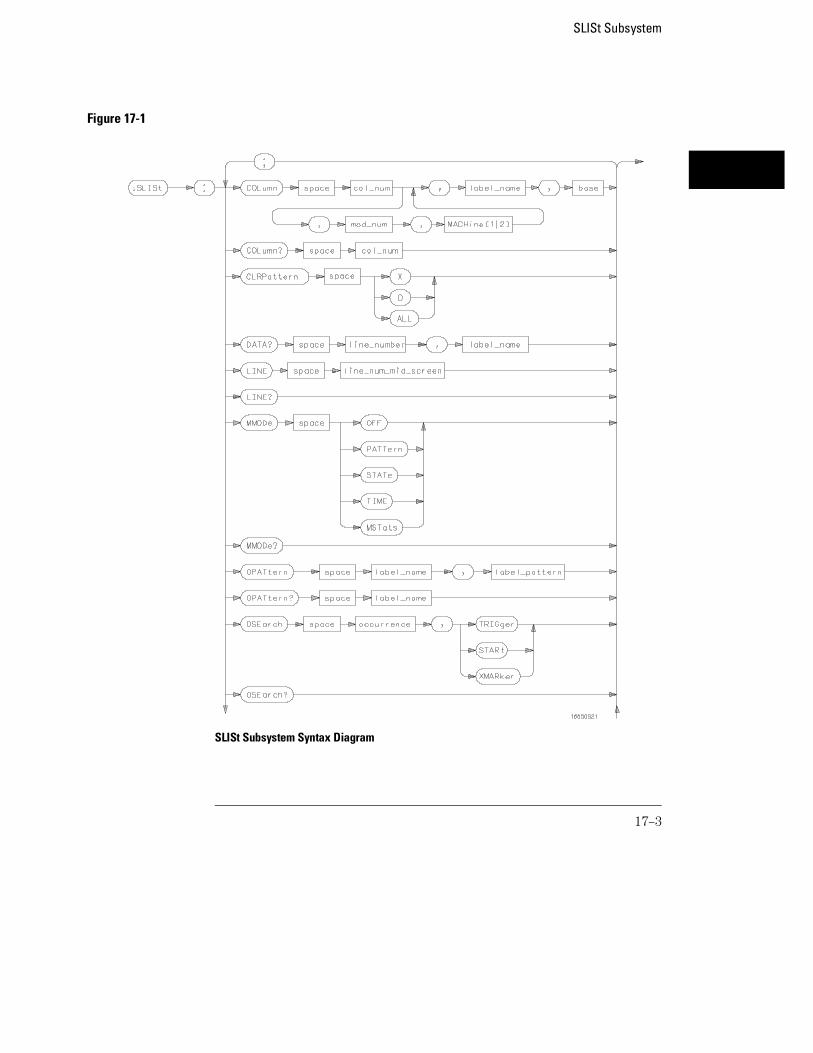
Figure 17-1
SLISt Subsystem Syntax Diagram
SLISt Subsystem
17–3
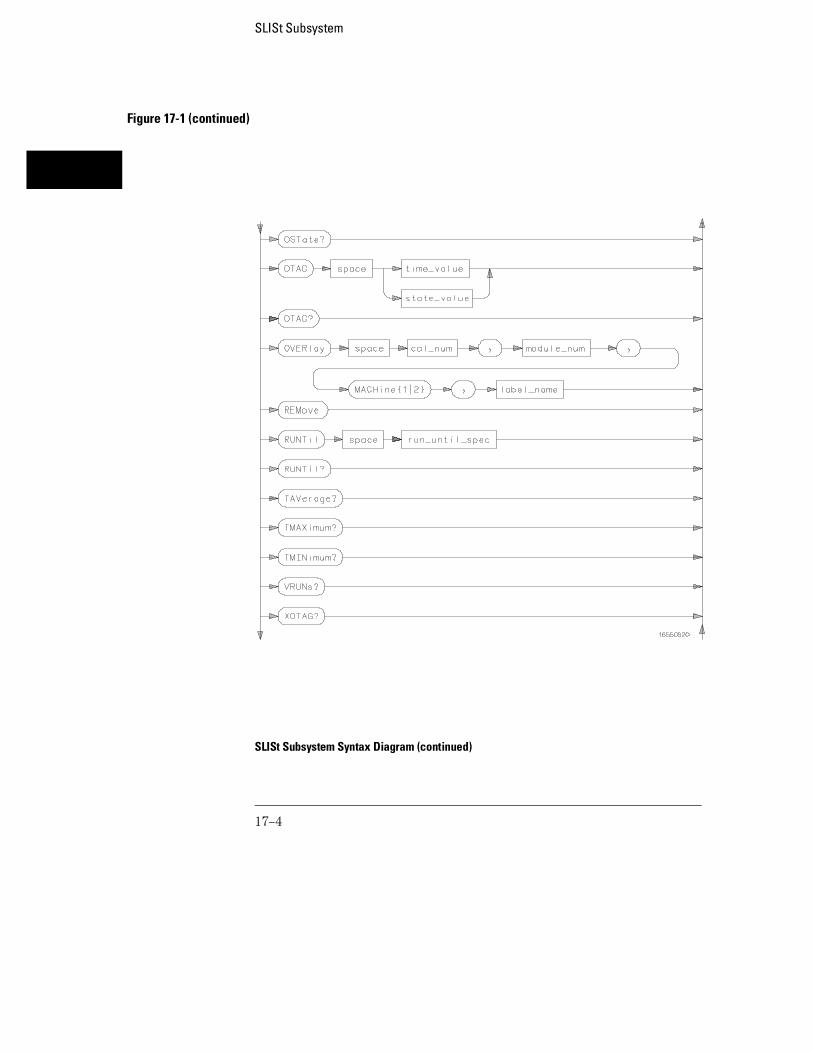
Figure 17-1 (continued)
SLISt Subsystem Syntax Diagram (continued)
SLISt Subsystem
17–4

Figure 17-1 (continued)
SLISt Subsystem Syntax Diagram (continued)
SLISt Subsystem
17–5

Table 17-1 SLISt Parameter Values
Parameter Values
module_num {1|2|3|4|5|6|7|8} (2 through 10 not used)
mach_num {1|2}
col_num Integer from 1 to 61
line_number Integer from −8191 to +8191
label_name A string of up to 6 alphanumeric characters
base {BINary|HEXadecimal|OCTal|DECimal|TWOS|ASCii|SYMBol|IASSembler} for labels or{ABSolute|RELative} for tags
line_num_mid_screen Integer from −8191 to +8191
label_pattern "{#B{0|1|X} . . . |#Q{0|1|2|3|4|5|6|7|X} . . . |#H{0|1|2|3|4|5|6|7|8|9|A|B|C|D|E|F|X} . .. |{0|1|2|3|4|5|6|7|8|9} . . . }"
occurrence Integer from −8191 to +8192
time_value Real number
state_value Real number
run_until_spec {OFF|LT,<value>|GT,<value>|INRange,<value>,
<value>|OUTRange,<value>,<value>}
value Real number
SLISt Subsystem
17–6

SLISt
Selector :MACHine{1|2}:SLISt
The SLISt selector is used as part of a compound header to access thosesettings normally found in the State Listing menu. It always follows theMACHine selector because it selects a branch directly below the MACHinelevel in the command tree.
Example OUTPUT XXX;":MACHINE1:SLIST:LINE 256"
COLumn
Command :MACHine{1|2}:SLISt:COLumn <col_num>[,<module_num>, MACHine{1|2}],<label_name>,<base>
The COLumn command allows you to configure the state analyzer list displayby assigning a label name and base to one of the 61 vertical columns in themenu. A column number of 1 refers to the left most column. When a label isassigned to a column it replaces the original label in that column.
When the label name is "TAGS," the TAGS column is assumed and the nextparameter must specify RELative or ABSolute.
A label for tags must be assigned in order to use ABSolute or RELative statetagging.
SLISt SubsystemSLISt
17–7

<col_num> integer from 1 to 61
<module_num> {1|2|3|4|5|6|7|8|9|10} (2 through 10 not used)
<label_name> string of up to 6 alphanumeric characters
<base> {BINary|HEXadecimal|OCTal|DECimal|TWOS|ASCii|SYMBol|IASSembler} for labelsor{ABSolute|RELative} for tags
Example OUTPUT XXX;":MACHINE1:SLIST:COLUMN 4,’A’,HEX"
Query :MACHine{1|2}:SLISt:COLumn? <col_num>
The COLumn query returns the column number, label name, and base for thespecified column.
Returned Format [:MACHine{1|2}:SLISt:COLumn] <col_num>,<module_num>,MACHine{1|2},<label_name>,<base><NL>
Example OUTPUT XXX;":MACHINE1:SLIST:COLUMN? 4"
CLRPattern
Command :MACHine{1|2}:SWAVeform:CLRPattern {X|O|ALL}
The CLRPattern command allows you to clear the patterns in the selectedSpecify Patterns menu.
Example OUTPUT XXX;":MACHINE1:SWAVEFORM:CLRPATTERN X"
SLISt SubsystemCLRPattern
17–8
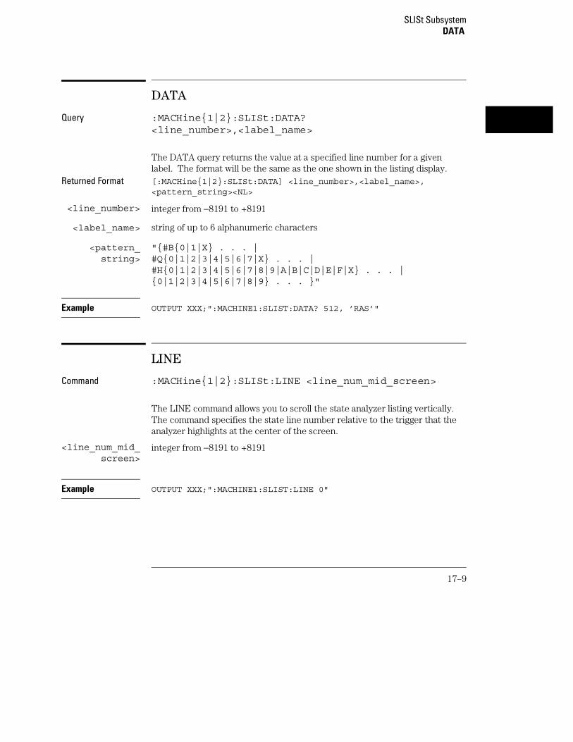
DATA
Query :MACHine{1|2}:SLISt:DATA?<line_number>,<label_name>
The DATA query returns the value at a specified line number for a givenlabel. The format will be the same as the one shown in the listing display.
Returned Format [:MACHine{1|2}:SLISt:DATA] <line_number>,<label_name>,<pattern_string><NL>
<line_number> integer from −8191 to +8191
<label_name> string of up to 6 alphanumeric characters
<pattern_string>
"{#B{0|1|X} . . . |#Q{0|1|2|3|4|5|6|7|X} . . . |#H{0|1|2|3|4|5|6|7|8|9|A|B|C|D|E|F|X} . . . |{0|1|2|3|4|5|6|7|8|9} . . . }"
Example OUTPUT XXX;":MACHINE1:SLIST:DATA? 512, ’RAS’"
LINE
Command :MACHine{1|2}:SLISt:LINE <line_num_mid_screen>
The LINE command allows you to scroll the state analyzer listing vertically.The command specifies the state line number relative to the trigger that theanalyzer highlights at the center of the screen.
<line_num_mid_screen>
integer from −8191 to +8191
Example OUTPUT XXX;":MACHINE1:SLIST:LINE 0"
SLISt SubsystemDATA
17–9

Query :MACHine{1|2}:SLISt:LINE?
The LINE query returns the line number for the state currently in the box atthe center of the screen.
Returned Format [:MACHine{1|2}:SLISt:LINE] <line_num_mid_screen><NL>
Example OUTPUT XXX;":MACHINE1:SLIST:LINE?"
MMODe
Command :MACHine{1|2}:SLISt:MMODe <marker_mode>
The MMODe command (Marker Mode) selects the mode controlling themarker movement and the display of marker readouts. When PATTern isselected, the markers will be placed on patterns. When STATe is selectedand state tagging is on, the markers move on qualified states countedbetween normally stored states. When TIME is selected and time tagging isenabled, the markers move on time between stored states. When MSTats isselected and time tagging is on, the markers are placed on patterns, but thereadouts will be time statistics.
<marker_mode> {OFF|PATTern|STATe|TIME|MSTats}
Example OUTPUT XXX;":MACHINE1:SLIST:MMODE TIME"
Query :MACHine{1|2}:SLISt:MMODe?
The MMODe query returns the current marker mode selected.Returned Format: [:MACHine{1|2}:SLISt:MMODe] <marker_mode><NL>
Example OUTPUT XXX;":MACHINE1:SLIST:MMODE?"
SLISt SubsystemMMODe
17–10

OPATtern
Command :MACHine{1|2}:SLISt:OPATtern<label_name>,<label_pattern>
The OPATtern command allows you to construct a pattern recognizer termfor the O Marker which is then used with the OSEarch criteria when movingthe marker on patterns. Because this command deals with only one label at atime, a complete specification could require several invocations.
When the value of a pattern is expressed in binary, it represents the bitvalues for the label inside the pattern recognizer term. In whatever base isused, the value must be between 0 and 232 − 1, since a label may not havemore than 32 bits. Because the <label_pattern> parameter may containdon’t cares, it is handled as a string of characters rather than a number.
<label_name> string of up to 6 alphanumeric characters
<label_pattern> "{#B{0|1|X} . . . |#Q{0|1|2|3|4|5|6|7|X} . . . |#H{0|1|2|3|4|5|6|7|8|9|A|B|C|D|E|F|X} . . . |{0|1|2|3|4|5|6|7|8|9} . . . }"
Examples OUTPUT XXX;":MACHINE1:SLIST:OPATTERN ’DATA’,’255’ "OUTPUT XXX;":MACHINE1:SLIST:OPATTERN ’ABC’,’#BXXXX1101’ "
Query :MACHine{1|2}:SLISt:OPATtern? <label_name>
The OPATtern query returns the pattern specification for a given label name.Returned Format [:MACHine{1|2}:SLISt:OPATtern]
<label_name>,<label_pattern><NL>
Example OUTPUT XXX;":MACHINE1:SLIST:OPATTERN? ’A’"
SLISt SubsystemOPATtern
17–11

OSEarch
Command :MACHine{1|2}:SLISt:OSEarch <occurrence>,<origin>
The OSEarch command defines the search criteria for the O marker, which isthen used with associated OPATtern recognizer specification when movingthe markers on patterns. The origin parameter tells the marker to begin asearch with the trigger, the start of data, or with the X marker. The actualoccurrence the marker searches for is determined by the occurrenceparameter of the OSEarch recognizer specification, relative to the origin. Anoccurrence of 0 places the marker on the selected origin. With a negativeoccurrence, the marker searches before the origin. With a positiveoccurrence, the marker searches after the origin.
<occurrence> integer from −8191 to +8191
<origin> {TRIGger|STARt|XMARker}
Example OUTPUT XXX;":MACHINE1:SLIST:OSEARCH +10,TRIGGER"
Query :MACHine{1|2}:SLISt:OSEarch?
The OSEarch query returns the search criteria for the O marker. Returned Format [:MACHine{1|2}:SLISt:OSEarch] <occurrence>,<origin><NL>
Example OUTPUT XXX;":MACHINE1:SLIST:OSEARCH?"
SLISt SubsystemOSEarch
17–12

OSTate
Query :MACHine{1|2}:SLISt:OSTate?
The OSTate query returns the line number in the listing where the O markerresides (−8191 to +8191). If data is not valid, the query returns 32767.
Returned Format [:MACHine{1|2}:SLISt:OSTate] <state_num><NL>
<state_num> an integer from −8191 to +8191, or 32767
Example OUTPUT XXX;":MACHINE1:SLIST:OSTATE?"
OTAG
Command :MACHine{1|2}:SLISt:OTAG<time_value>|<state_value>}
The OTAG command specifies the tag value on which the O Marker should beplaced. The tag value is time when time tagging is on, or states when statetagging is on. If the data is not valid tagged data, no action is performed.
<time_value> real number
<state_value> integer
Example :OUTPUT XXX;":MACHINE1:SLIST:OTAG 40.0E−6"
SLISt SubsystemOSTate
17–13

Query :MACHine{1|2}:SLISt:OTAG?
The OTAG query returns the O Marker position in time when time tagging ison or in states when state tagging is on, regardless of whether the markerwas positioned in time or through a pattern search. If data is not valid, thequery returns 9.9E37 for time tagging, or returns 32767 for state tagging.
Returned Format [:MACHine{1|2}:SLISt:OTAG] {time_value>|<state_value>}<NL>
<time_value> real number
<state_value> integer
Example OUTPUT XXX;":MACHINE1:SLIST:OTAG?"
OVERlay
Command :MACHine{1|2}:SLISt:OVERlay<col_num>,<module_num>,MACHine{1|2},<label_name>
The OVERlay command allows you to add time-correlated labels from othermodules or machines to the state listing.
<col_num> integer from 1 to 61
<Module_num> integer 1 through 10 (2 through 10 unused)
<label_name> string of up to 6 alphanumeric characters
Example OUTPUT XXX;":MACHINE1:SLIST:OVERlay,25,5,MACHINE2,’DATA’"
SLISt SubsystemOVERlay
17–14

REMove
Command :MACHine{1|2}:SLISt:REMove
The REMove command removes all labels, except the leftmost label, fromthe listing menu.
Example OUTPUT XXX;":MACHINE1:SLIST:REMOVE"
RUNTil
Command :MACHine{1|2}:SLISt:RUNTil <run_until_spec>
The RUNTil (run until) command allows you to define a stop condition whenthe trace mode is repetitive. Specifying OFF causes the analyzer to makeruns until either the display’s STOP field is touched, or, when the STOPcommand is issued.
There are four conditions based on the time between the X and O markers.Using this difference in the condition is effective only when time tags havebeen turned on (see the TAG command in the STRace subsystem). Thesefour conditions are as follows:
• The difference is less than (LT) some value.
• The difference is greater than (GT) some value.
• The difference is inside some range (INRange).
• The difference is outside some range (OUTRange).
End points for the INRange and OUTRange should be at least 8 ns apart sincethis is the minimum time resolution of the time tag counter.
SLISt SubsystemREMove
17–15

There are two conditions which are based on a comparison of the acquiredstate data and the compare data image. The analyzer can run until one of thefollowing conditions is true:
• Every channel of every label has the same value (EQUal).
• Any channel of any label has a different value (NEQual).
The RUNTil instruction (for state analysis) is available in both the SLISt andCOMPare subsystems.
<run_until_spec>
{OFF|LT,<value>|GT,<value>|INRange,<value>,<value>|OUTRange,<value>,<value>|EQUal|NEQual}
<value> real number from −9E9 to +9E9
Example OUTPUT XXX;":MACHINE1:SLIST:RUNTIL GT,800.0E−6"
Query :MACHine{1|2}:SLISt:RUNTil?
The RUNTil query returns the current stop criteria.Returned Format [:MACHine{1|2}:SLISt:RUNTil] <run_until_spec><NL>
Example OUTPUT XXX;":MACHINE1:SLIST:RUNTIL?"
SLISt SubsystemRUNTil
17–16

TAVerage
Query :MACHine{1|2}:SLISt:TAVerage?
The TAVerage query returns the value of the average time between the Xand O Markers. If the number of valid runs is zero, the query returns 9.9E37.Valid runs are those where the pattern search for both the X and O markerswas successful, resulting in valid delta-time measurements.
Returned Format: [:MACHine{1|2}:SLISt:TAVerage] <time_value><NL>
<time_value> real number
Example OUTPUT XXX;":MACHINE1:SLIST:TAVERAGE?"
TMAXimum
Query :MACHine{1|2}:SLISt:TMAXimum?
The TMAXimum query returns the value of the maximum time between the Xand O Markers. If data is not valid, the query returns 9.9E37.
Returned Format [:MACHine{1|2}:SLISt:TMAXimum] <time_value><NL>
<time_value> real number
Example OUTPUT XXX;":MACHINE1:SLIST:TMAXIMUM?"
SLISt SubsystemTAVerage
17–17

TMINimum
Query :MACHine{1|2}:SLISt:TMINimum?
The TMINimum query returns the value of the minimum time between the Xand O Markers. If data is not valid, the query returns 9.9E37.
Returned Format [:MACHine{1|2}:SLISt:TMINimum] <time_value><NL>
<time_value> real number
Example: OUTPUT XXX;":MACHINE1:SLIST:TMINIMUM?"
VRUNs
Query :MACHine{1|2}:SLISt:VRUNs?
The VRUNs query returns the number of valid runs and total number of runsmade. Valid runs are those where the pattern search for both the X and Omarkers was successful resulting in valid delta time measurements.
Returned Format [:MACHine{1|2}:SLISt:VRUNs] <valid_runs>,<total_runs><NL>
<valid_runs> zero or positive integer
<total_runs> zero or positive integer
Example: OUTPUT XXX;":MACHINE1:SLIST:VRUNS?"
SLISt SubsystemTMINimum
17–18

XOTag
Query :MACHine{1|2}:SLISt:XOTag?
The XOTag query returns the time from the X to O markers when the markermode is time or number of states from the X to O markers when the markermode is state. If there is no data in the time mode the query returns 9.9E37.If there is no data in the state mode, the query returns 32767.
Returned Format [:MACHine{1|2}:SLISt:XOTag] {<XO_time>|<XO_states>}<NL>
<XO_time> real number
<XO_states> integer
Example OUTPUT XXX;":MACHINE1:SLIST:XOTAG?"
XOTime
Query :MACHine{1|2}:SLISt:XOTime?
The XOTime query returns the time from the X to O markers when themarker mode is time or number of states from the X to O markers when themarker mode is state. If there is no data in the time mode the query returns9.9E37. If there is no data in the state mode, the query returns 32767.
Returned Format [:MACHine{1|2}:SLISt:XOTime] {<XO_time>|<XO_states>}<NL>
<XO_time> real number
<XO_states> integer
Example OUTPUT XXX;":MACHINE1:SLIST:XOTIME?"
SLISt SubsystemXOTag
17–19

XPATtern
Command :MACHine{1|2}:SLISt:XPATtern <label_name>,<label_pattern>
The XPATtern command allows you to construct a pattern recognizer termfor the X Marker which is then used with the XSEarch criteria when movingthe marker on patterns. Since this command deals with only one label at atime, a complete specification could require several invocations.
When the value of a pattern is expressed in binary, it represents the bitvalues for the label inside the pattern recognizer term. In whatever base isused, the value must be between 0 and 232 − 1, since a label may not havemore than 32 bits. Because the <label_pattern> parameter may containdon’t cares, it is handled as a string of characters rather than a number.
<label_name> string of up to 6 alphanumeric characters
<label_pattern> "{#B{0|1|X} . . . |#Q{0|1|2|3|4|5|6|7|X} . . . |#H{0|1|2|3|4|5|6|7|8|9|A|B|C|D|E|F|X} . . . |{0|1|2|3|4|5|6|7|8|9} . . . }"
Examples OUTPUT XXX;":MACHINE1:SLIST:XPATTERN ’DATA’,’255’ "OUTPUT XXX;":MACHINE1:SLIST:XPATTERN ’ABC’,’#BXXXX1101’ "
Query :MACHine{1|2}:SLISt:XPATtern? <label_name>
The XPATtern query returns the pattern specification for a given label name.Returned Format [:MACHine{1|2}:SLISt:XPATtern]
<label_name>,<label_pattern><NL>
Example OUTPUT XXX;":MACHINE1:SLIST:XPATTERN? ’A’"
SLISt SubsystemXPATtern
17–20

XSEarch
Command :MACHine{1|2}:SLISt:XSEarch <occurrence>,<origin>
The XSEarch command defines the search criteria for the X Marker, which isthen with associated XPATtern recognizer specification when moving themarkers on patterns. The origin parameter tells the Marker to begin a searchwith the trigger or with the start of data. The occurrence parameterdetermines which occurrence of the XPATtern recognizer specification,relative to the origin, the marker actually searches for. An occurrence of 0places a marker on the selected origin.
<occurrence> integer from −8191 to +8191
<origin> {TRIGger|STARt}
Example OUTPUT XXX;":MACHINE1:SLIST:XSEARCH +10,TRIGGER"
Query :MACHine{1|2}:SLISt:XSEarch?
The XSEarch query returns the search criteria for the X marker. Returned Format [:MACHine{1|2}:SLISt:XSEarch] <occurrence>,<origin><NL>
Example OUTPUT XXX;":MACHINE1:SLIST:XSEARCH?"
SLISt SubsystemXSEarch
17–21

XSTate
Query :MACHine{1|2}:SLISt:XSTate?
The XSTate query returns the line number in the listing where the X markerresides (−8191 to +8191). If data is not valid, the query returns 32767.
Returned Format [:MACHine{1|2}:SLISt:XSTate] <state_num><NL>
<state_num> integer from −8191 to +8191, or 32767
Example OUTPUT XXX;":MACHINE1:SLIST:XSTATE?"
XTAG
Command :MACHine{1|2}:SLISt:XTAG{<time_value>|<state_value>}
The XTAG command specifies the tag value on which the X Marker should beplaced. The tag value is time when time tagging is on or states when statetagging is on. If the data is not valid tagged data, no action is performed.
<time_value> real number
<state_value> integer
Example OUTPUT XXX;":MACHINE1:SLIST:XTAG 40.0E−6"
SLISt SubsystemXSTate
17–22

Query :MACHine{1|2}:SLISt:XTAG?
The XTAG query returns the X Marker position in time when time tagging ison or in states when state tagging is on, regardless of whether the markerwas positioned in time or through a pattern search. If data is not valid taggeddata, the query returns 9.9E37 for time tagging, or retruns 32767 for statetagging.
Returned Format [:MACHine{1|2}:SLISt:XTAG] {<time_value>|<state_value>}<NL>
Example OUTPUT XXX;":MACHINE1:SLIST:XTAG?"
SLISt SubsystemXTAG
17–23

17–24

18
SWAVeform Subsystem
Introduction
The commands in the State Waveform subsystem allow you toconfigure the display so that you can view state data as waveforms onup to 96 channels identified by label name and bit number. The 11commands are analogous to their counterparts in the TimingWaveform subsystem. However, in this subsystem the x-axis isrestricted to representing only samples (states), regardless ofwhether time tagging is on or off. As a result, the only commandswhich can be used for scaling are DELay and RANge.
The way to manipulate the X and O markers on the Waveform displayis through the State Listing (SLISt) subsystem. Using the markercommands from the SLISt subsystem will affect the markers on theWaveform display.
The commands in the SWAVeform subsystem are:
• ACCumulate
• ACQuisition
• CENter
• CLRPattern
• CLRStat
• DELay
• INSert
• RANGe
• REMove
• TAKenbranch
• TPOSition
18–2

Figure 18-1
SWAVeform Subsystem Syntax Diagram
SWAVeform Subsystem
18–3

Table 18-1 SWAVeform Parameter Values
Parameter Value
number_of_samples integer from −8191 to +8191
label_name string of up to 6 alphanumeric characters
bit_id {OVERlay|<bit_num>|ALL}
bit_num integer representing a label bit from 0 to 31
range_values integer from 10 to 5000 (representing (10 × states/Division))
mark_type {X|O|XO|TRIGger}
percent integer from 0 to 100
SWAVeform
Selector :MACHine{1|2}:SWAVeform
The SWAVeform (State Waveform) selector is used as part of a compoundheader to access the settings in the State Waveform menu. It always followsthe MACHine selector because it selects a branch directly below theMACHine level in the command tree.
Example OUTPUT XXX;":MACHINE2:SWAVEFORM:RANGE 40"
SWAVeform SubsystemSWAVeform
18–4

ACCumulate
Command :MACHine{1|2}:SWAVeform:ACCumulate{{ON|1}|{OFF|0}}
The ACCumulate command allows you to control whether the waveformdisplay gets erased between individual runs or whether subsequentwaveforms are allowed to be displayed over the previous waveforms.
Example OUTPUT XXX;":MACHINE1:SWAVEFORM:ACCUMULATE ON"
Query :MACHine{1|2}:SWAVeform:ACCumulate?
The ACCumulate query returns the current setting. The query always showsthe setting as the characters, "0" (off) or "1" (on).
Returned Format [:MACHine{1|2}:SWAVeform:ACCumulate] {0|1}<NL>
Example OUTPUT XXX;":MACHINE1:SWAVEFORM:ACCUMULATE?"
ACQuisition
Command :MACHine{1|2}:SWAVeform:ACQuisition{AUTOmatic|MANual}
The ACQuisition command allows you to specify the acquisition mode for thestate analyzer. The acquisition modes are automatic and manual.
Example OUTPUT XXX;":MACHINE2:SWAVEFORM:ACQUISITION AUTOMATIC"
SWAVeform SubsystemACCumulate
18–5

Query :MACHine{1|2}:SWAVeform:ACQuisition?
The ACQusition query returns the current acquisition mode.Returned Format [:MACHine{1|2}:SWAVeform:ACQuisition] {AUTOmatic|MANual}<NL>
Example OUTPUT XXX;":MACHINE2:SWAVEFORM:ACQUISITION?"
CENTer
Command :MACHine{1|2}:SWAVeform:CENTer <marker_type>
The CENTer command allows you to center the waveform display about thespecified markers. The markers are placed on the waveform in the SLIStsubsystem.
<marker_type> {X|O|XO|TRIGger}
Example OUTPUT XXX;":MACHINE1:SWAVEFORM:CENTER X"
CLRPattern
Command :MACHine{1|2}:SWAVeform:CLRPattern {X|O|ALL}
The CLRPattern command allows you to clear the patterns in the selectedSpecify Patterns menu.
Example OUTPUT XXX;":MACHINE1:SWAVEFORM:CLRPATTERN"
SWAVeform SubsystemCENTer
18–6

CLRStat
Command :MACHine{1|2}:SWAVeform:CLRStat
The CLRStat command allows you to clear the waveform statistics withouthaving to stop and restart the acquisition.
Example OUTPUT XXX;":MACHINE1:SWAVEFORM:CLRSTAT"
DELay
Command :MACHine{1|2}:SWAVeform:DELay <number_of_samples>
The DELay command allows you to specify the number of samples betweenthe State trigger and the horizontal center of the screen for the waveformdisplay. The allowed number of samples is from −8191 to +8191.
<number_of_samples>
integer from –8191 to +8191
Example OUTPUT XXX;":MACHINE2:SWAVEFORM:DELAY 127"
Query :MACHine{1|2}:SWAVeform:DELay?
The DELay query returns the current sample offset value.Returned Format [:MACHine{1|2}:SWAVeform:DELay] <number_of_samples><NL>
<number_of_samples>
integer from –8191 to +8191
Example OUTPUT XXX;":MACHINE1:SWAVEFORM:DELAY?"
SWAVeform SubsystemCLRStat
18–7

INSert
Command :MACHine{1|2}:SWAVeform:INSert<label_name>,<bit_id>
The INSert command allows you to add waveforms to the state waveformdisplay. Waveforms are added from top to bottom on the screen. When 96waveforms are present, inserting additional waveforms replaces the lastwaveform. Bit numbers are zero based, so a label with 8 bits is referenced asbits 0 through 7. Specifying OVERlay causes a composite waveform displayof all bits or channels for the specified label.
<label_name> string of up to 6 alphanumeric characters
<bit_id> {OVERlay|<bit_num>ALL}
<bit_num> integer representing a label bit from 0 to 31
Examples OUTPUT XXX;":MACHINE1:SWAVEFORM:INSERT ’WAVE’, 19"OUTPUT XXX;":MACHINE1:SWAVEFORM:INSERT ’ABC’, OVERLAY"OUTPUT XXX;":MACH1:SWAV:INSERT ’POD1’, #B1001"
RANGe
Command :MACHine{1|2}:SWAVeform:RANGe <number_of_samples>
The RANGe command allows you to specify the number of samples acrossthe screen on the State Waveform display. It is equivalent to ten times thestates per division setting (states/Div) on the front panel. A number between10 and 5000 may be entered.
<number_of_samples>
integer from 10 to 5000
Example OUTPUT XXX;":MACHINE2:SWAVEFORM:RANGE 80"
SWAVeform SubsystemINSert
18–8

Query :MACHine{1|2}:SWAVeform:RANGe?
The RANGe query returns the current range value.Returned Format [:MACHine{1|2}:SWAVeform:RANGe] <number_of_samples><NL>
<number_of_samples>
integer from 10 to 5000
Example OUTPUT XXX;":MACHINE2:SWAVEFORM:RANGE?"
REMove
Command :MACHine{1|2}:SWAVeform:REMove
The REMove command allows you to clear the waveform display beforebuilding a new display.
Example OUTPUT XXX;":MACHINE1:SWAVEFORM:REMOVE"
TAKenbranch
Command :MACHine{1|2}:SWAVeform:TAKenbranch{STORe|NOSTore}
The TAKenbranch command allows you to control whether the states thatcause branching are stored or not stored. This command is only availablewhen the acquisition mode is set to manual.
Example OUTPUT XXX;":MACHINE2:SWAVEFORM:TAKENBRANCH STORE"
SWAVeform SubsystemREMove
18–9

Query :MACHine{1|2}:SWAVeform:TAKenbranch?
The TAKenbranch query returns the current setting.Returned Format [:MACHine{1|2}:SWAVeform:TAKenbranch] {STORe|NOSTore}<NL>
Example OUTPUT XXX;":MACHINE2:SWAVEFORM:TAKENBRANCH?"
TPOSition
Command :MACHine{1|2}:SWAVeform:TPOSition{STARt|CENTer|END|POSTstore,<percent>}
The TPOSition command allows you to control where the trigger point isplaced. The trigger point can be placed at the start, center, end, or at apercentage of post store. The post store option is the same as the UserDefined option when setting the trigger point from the front panel.
The TPOSition command is only available when the acquisition mode is set tomanual.
<percent> integer from 1 to 100
Example OUTPUT XXX;":MACHINE2:SWAVEFORM:TPOSITION CENTER"
SWAVeform SubsystemTPOSition
18–10

Query :MACHine{1|2}:SWAVeform:TPOSition?
The TPOSition query returns the current trigger setting.Returned Format [:MACHine{1|2}:SWAVeform:TPOSition]
{STARt|CENTer|END|POSTstore,<percent>}<NL>
<percent> integer from 1 to 100
Example OUTPUT XXX;":MACHINE2:SWAVEFORM:TPOSition?"
SWAVeform SubsystemTPOSition
18–11

18–12

19
SCHart Subsystem
Introduction
The State Chart subsystem provides the commands necessary forprogramming the Chart display of 1660A-series logic analyzers. Thecommands allow you to build charts of label activity, using datanormally found in the Listing display. The chart’s Y-axis is used toshow data values for the label of your choice. The X-axis can be usedin two different ways. In one, the X-axis represents states (shown asrows in the State Listing display). In the other, the X-axis representsthe data values for another label. When states are plotted along theX-axis, X and O markers are available. Because the State Chartdisplay is simply an alternative way of looking at the data in the StateListing, the X and O markers can be manipulated through the SLIStsubsystem. Because the programming commands do not force themenus to switch, you can position the markers in the SLISt subsystemand see the effects in the State Chart display.
The commands in the SCHart subsystem are:
• ACCumulate
• HAXis
• VAXis
19–2

Figure 19-1
SCHart Subsystem Syntax Diagram
SCHart Subsystem
19–3
Table 19-1 SCHart Parameter Values
Parameter Values
state_low_value integer from –8191 to +8191
state_high_value integer from <state_low_value> to +8191
label_name string of up to 6 alphanumeric characters
label_low_value string from 0 to 232 − 1 (#HFFFF)
label_high_value string from <label_low_value> to 232 − 1 (#HFFFF)
low_value string from 0 to 232 − 1 (#HFFFF)
high_value string from low_value to 232 − 1 (#HFFFF)
SCHart
Selector :MACHine{1|2}:SCHart
The SCHart selector is used as part of a compound header to access thesettings found in the State Chart menu. It always follows the MACHineselector because it selects a branch below the MACHine level in thecommand tree.
Example OUTPUT XXX;":MACHINE1:SCHART:VAXIS ’A’, ’0’, ’9’"
ACCumulate
Command :MACHine{1|2}:SCHart:ACCumulate {{ON|1}|{OFF|0}}
The ACCumulate command allows you to control whether the chart displaygets erased between each individual run or whether subsequent waveformsare allowed to be displayed over the previous waveforms.
SCHart SubsystemSCHart
19–4

Example OUTPUT XXX;":MACHINE1:SCHART:ACCUMULATE OFF"
Query :MACHine{1|2}:SCHart:ACCumulate?
The ACCumulate query returns the current setting. The query always showsthe setting as the character "0" (off) or "1" (on).
Returned Format [:MACHine{1|2}:SCHart:ACCumulate] {0|1}<NL>
Example OUTPUT XXX;":MACHINE1:SCHART:ACCUMULATE?"
HAXis
Command :MACHine{1|2}:SCHart:HAXis {STAtes,<state_low_value>,<state_high_value>|<label_name>,<label_low_value>,<label_high_value>}
The HAXis command allows you to select whether states or a label’s valueswill be plotted on the horizontal axis of the chart. The axis is scaled byspecifying the high and low values.
The shortform for STATES is STA. This is an intentional deviation from thenormal truncation rule.
SCHart SubsystemHAXis
19–5

<state_low_value>
integer from −8191 to +8191
<state_high_value>
integer from <state_low_value> to +8191
<label_name> string of up to 6 alphanumeric characters
<label_low_value>
string from 0 to 232−−1 (#HFFFF)
<label_high_value>
string from <label_low_value> to 232–1 (#HFFFF)
Examples OUTPUT XXX;":MACHINE1:SCHART:HAXIS STATES, −100, 100"OUTPUT XXX;":MACHINE1:SCHART:HAXIS ’READ’, ’−511’, ’511’"
Query :MACHine{1|2}:SCHart:HAXis?
The HAXis query returns the current horizontal axis label and scaling.Returned Format [:MACHine{1|2}:SCHart:HAXis] {STAtes,<state_low_value>,
<state_high_value>|<label_name>,<label_low_value>,<label_high_value>}
Example OUTPUT XXX;":MACHINE1:SCHART:HAXIS?"
SCHart SubsystemHAXis
19–6

VAXis
Command :MACHine{1|2}:SCHart:VAXis<label_name>,<low_value>,<high_value>
The VAXis command allows you to choose which label will be plotted on thevertical axis of the chart and scale the vertical axis by specifying the highvalue and low value.
<label_name> string of up to 6 alphanumeric characters
<low_value> string from 0 to 232−1 (#HFFFF)
<high_value> string from <low_value> to 232−1 (#HFFFF)
Examples OUTPUT XXX;":MACHINE2:SCHART:VAXIS ’SUM1’, ’0’, ’99’"OUTPUT XXX;":MACHINE1:SCHART:VAXIS ’BUS’, ’#H00FF’, ’#H0500’"
Query :MACHine{1|2}:SCHart:VAXis?
The VAXis query returns the current vertical axis label and scaling.Returned Format [:MACHine{1|2}:SCHart:VAXis] <label_name>,<low_value>,
<high_value><NL>
Example OUTPUT XXX;":MACHINE1:SCHART:VAXIS?"
SCHart SubsystemVAXis
19–7

19–8

20
COMPare Subsystem

Introduction
Commands in the state COMPare subsystem provide the ability to do abit-by-bit comparison between the acquired state data listing and acompare data image. The commands are:
• CLEar
• CMASk
• COPY
• DATA
• FIND
• LINE
• MENU
• RANGe
• RUNTil
• SET
20–2

Figure 20-1
COMPare Subsystem Syntax Diagram
COMPare Subsystem
20–3

Table 20-1 Compare Parameter Values
Parameter Values
label_name string of up to 6 characters
care_spec string of characters "{*|.}..."
* care
. don’t care
line_num integer from –8191 to +8191
data_pattern "{B{0|1|X} . . . |#Q{0|1|2|3|4|5|6|7|X} . . . |#H{0|1|2|3|4|5|6|7|8|9|A|B|C|D|E|F|X} .. . |{0|1|2|3|4|5|6|7|8|9} . . . }"
difference_occurence integer from 1 to 8192
start_line integer from –8191 to +8191
stop_line integer from <start_line> to +8191
COMPare
Selector :MACHine{1|2}:COMPare
The COMPare selector is used as part of a compound header to access thesettings found in the Compare menu. It always follows the MACHine selectorbecause it selects a branch directly below the MACHine level in the commandtree.
Example OUTPUT XXX;":MACHINE1:COMPARE:FIND? 819"
COMPare SubsystemCOMPare
20–4

CLEar
Command :MACHine{1|2}:COMPare:CLEar
The CLEar command clears all "don’t cares" in the reference listing andreplaces them with zeros except when the CLEar command immediatelyfollows the SET command (see SET command).
Example OUTPUT XXX;":MACHINE2:COMPARE:CLEAR"
CMASk
Command :MACHine{1|2}:COMPare:CMASk<label_name>,<care_spec>
The CMASk (Compare Mask) command allows you to set the bits in thechannel mask for a given label in the compare listing image to "compares" or"don’t compares."
<label_name> A string of up to 6 alphanumeric characters
<care_spec> A string of characters "{*|.}..." (32 characters maximum)
<*> An indicator that tells the logic analyzer that it cares about this bit.
<.> An indicator that tells the logic analyzer that it does not care about this bit(don’t care).
Example OUTPUT XXX;":MACHINE2:COMPARE:CMASK ’DATA’, ’*.**..**’"
COMPare SubsystemCLEar
20–5

Query :MACHine{1|2}:COMPare:CMASk <label_name>?
The CMASk query returns the state of the bits in the channel mask for agiven label in the compare listing image.
Returned Format [:MACHine{1|2}:COMPare:CMASk] <label_name>,<care_spec>
<label name> A string of up to 6 alphanumeric characters
<care_spec> A string of characters "{*|.}..." (32 characters maximum)
<*> An indicator that tells the logic analyzer that it cares about this bit.
<.> An indicator that tells the logic analyzer that it does not care about this bit(don’t care).
Example OUTPUT XXX;":MACHINE2:COMPARE:CMASK ’DATA’?"
COPY
Command :MACHine{1|2}:COMPare:COPY
The COPY command copies the current acquired State Listing for thespecified machine into the Compare Reference template. It does not affectthe compare range or channel mask settings.
Example OUTPUT XXX;":MACHINE2:COMPARE:COPY"
COMPare SubsystemCOPY
20–6

DATA
Command :MACHine{1|2}:COMPare:DATA {<label_name>,<line_num>,<data_pattern>|<line_num>,<data_pattern>[, <data_pattern>]... }
The DATA command allows you to edit the compare listing image for a givenlabel and state row. When DATA is sent to an instrument where no compareimage is defined (such as at power-up) all other data in the image is set todon’t cares.
Not specifying the <label_name> parameter allows you to write datapatterns to more than one label for the given line number. The first patternis placed in the left-most label, with the following patterns being placed in aleft-to-right fashion (as seen on the Compare display). Specifying morepatterns than there are labels simply results in the extra patterns beingignored.
Because don’t cares (Xs) are allowed in the data pattern, it must always beexpressed as a string. You may still use different bases; although, don’t carescannot be used in a decimal number.
<label_name> A string of up to 6 alphanumeric characters
<line_num> An integer from –8191 to +8191
<data pattern> A string in one of the following forms:"{B{0|1|X} . . . |#Q{0|1|2|3|4|5|6|7|X} . . . |#H{0|1|2|3|4|5|6|7|8|9|A|B|C|D|E|F|X} . . . |{0|1|2|3|4|5|6|7|8|9} . . . }"
Examples OUTPUT XXX;":MACHINE2:COMPARE:DATA ’CLOCK’, 42, ’#B011X101X’"OUTPUT XXX;":MACHINE2:COMPARE:DATA ’OUT3’, 0, ’#HFF40’"OUTPUT XXX;":MACHINE1:COMPARE:DATA 129, ’#BXX00’, ’#B1101’,’#B10XX’"
OUTPUT XXX;":MACH2:COMPARE:DATA −511, ’4’, ’64’, ’16’, 256’,’8’, ’16’"
COMPare SubsystemDATA
20–7
Query :MACHine{1|2}:COMPare:DATA?<label_name>,<line_num>
The DATA query returns the value of the compare listing image for a givenlabel and state row.
Returned Format [:MACHine{1|2}:COMPare:DATA] <label_name>,<line_num>,<data_pattern><NL>
<label_name> A string of up to 6 alphanumeric characters
<line_num> An integer from –8191 to +8191
<data pattern> A string in one of the following forms:"{B{0|1|X} . . . |#Q{0|1|2|3|4|5|6|7|X} . . . |#H{0|1|2|3|4|5|6|7|8|9|A|B|C|D|E|F|X} . . . |{0|1|2|3|4|5|6|7|8|9} . . . }"
Example 10 DIM Label$[6], Response$[80]15 PRINT "This program shows the values for a signal’sCompare listing"20 INPUT "Enter signal label: ", Label$25 OUTPUT XXX;":SYSTEM:HEADER OFF" !Turn headers off (fromresponses)30 OUTPUT XXX;":MACHINE2:COMPARE:RANGE?"35 ENTER XXX; First, Last !Read in the range’s end-points40 PRINT "LINE ", "VALUE of "; Label$45 FOR State = First TO Last !Print compare value for eachstate50 OUTPUT XXX;":MACH2:COMPARE:DATA? ’" & Label$ & "’," &VAL$(State)55 ENTER XXX; Response$60 PRINT State, Response$65 NEXT State70 END
COMPare SubsystemDATA
20–8

FIND
Query :MACHine{1|2}:COMPare:FIND?<difference_occurrence>
The FIND query is used to get the line number of a specified differenceoccurence (first, second, third, etc) within the current compare range, asdictated by the RANGe command (see page 20-11). A difference is countedfor each line where at least one of the current labels has a discrepancybetween its acquired state data listing and its compare data image.
Invoking the FIND query updates both the Listing and Compare displays sothat the line number returned is in the center of the screen.
Returned Format [:MACHine{1|2}:COMPare:FIND] <difference_occurrence>,<line_number><NL>
<difference_occurrence>
integer from 1 to 8192
<line_number> integer from –8191 to +8191
Example OUTPUT XXX;":MACHINE2:COMPARE:FIND? 26"
COMPare SubsystemFIND
20–9
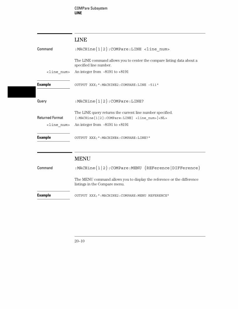
LINE
Command :MACHine{1|2}:COMPare:LINE <line_num>
The LINE command allows you to center the compare listing data about aspecified line number.
<line_num> An integer from –8191 to +8191
Example OUTPUT XXX;":MACHINE2:COMPARE:LINE –511"
Query :MACHine{1|2}:COMPare:LINE?
The LINE query returns the current line number specified.Returned Format [:MACHine{1|2}:COMPare:LINE] <line_num>}<NL>
<line_num> An integer from –8191 to +8191
Example OUTPUT XXX;":MACHINE4:COMPARE:LINE?"
MENU
Command :MACHine{1|2}:COMPare:MENU {REFerence|DIFFerence}
The MENU command allows you to display the reference or the differencelistings in the Compare menu.
Example OUTPUT XXX;":MACHINE2:COMPARE:MENU REFERENCE"
COMPare SubsystemLINE
20–10

RANGe
Command :MACHine{1|2}:COMPare:RANGe{FULL|PARTial,<start_line>,<stop_line>}
The RANGe command allows you to define the boundaries for thecomparison. The range entered must be a subset of the lines in the acquirememory.
<start_line> integer from –8191 to +8191
<stop_line> integer from <start_line> to +8191
Examples OUTPUT XXX;":MACHINE2:COMPARE:RANGE PARTIAL, –511, 512"OUTPUT XXX;":MACHINE2:COMPARE:RANGE FULL"
Query :MACHine{1|2}:COMPare:RANGe?
The RANGe query returns the current boundaries for the comparison.Returned Format [:MACHine{1|2}:COMPare:RANGe] {FULL|PARTial,<start_line>,
<stop_line>}<NL>
<start_line> integer from –8191 to +8191
<stop_line> integer from <start_line> to +8191
Example OUTPUT 707;":MACHINE1:COMPARE:RANGE?"
COMPare SubsystemRANGe
20–11

RUNTil
Command :MACHine{1|2}:COMPare:RUNTil {OFF| LT,<value>|GT,<value>|INRange,<value>,<value>|OUTRange,<value>,<value>|EQUal|NEQual}
The RUNTil (run until) command allows you to define a stop condition whenthe trace mode is repetitive. Specifying OFF causes the analyzer to makeruns until either the display’s STOP field is touched or the STOP command isissued.
There are four conditions based on the time between the X and O markers.Using this difference in the condition is effective only when time tags havebeen turned on (see the TAG command in the STRace subsystem). Thesefour conditions are as follows:
• The difference is less than (LT) some value.
• The difference is greater than (GT) some value.
• The difference is inside some range (INRange).
• The difference is outside some range (OUTRange).
End points for the INRange and OUTRange should be at least 8 ns apart sincethis is the minimum time resolution of the time tag counter.
There are two conditions which are based on a comparison of the acquiredstate data and the compare data image. You can run until one of thefollowing conditions is true:
• Every channel of every label has the same value (EQUal).
• Any channel of any label has a different value (NEQual).
The RUNTil instruction (for state analysis) is available in both the SLISt andCOMPare subsystems.
<value> real number from −9E9 to +9E9
COMPare SubsystemRUNTil
20–12
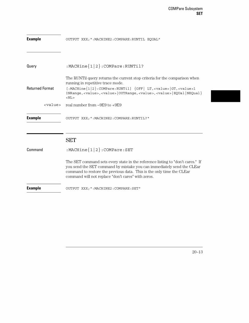
Example OUTPUT XXX;":MACHINE2:COMPARE:RUNTIL EQUAL"
Query :MACHine{1|2}:COMPare:RUNTil?
The RUNTil query returns the current stop criteria for the comparison whenrunning in repetitive trace mode.
Returned Format [:MACHine{1|2}:COMPare:RUNTil] {OFF| LT,<value>|GT,<value>lINRange,<value>,<value>|OUTRange,<value>,<value>|EQUal|NEQual}<NL>
<value> real number from −9E9 to +9E9
Example OUTPUT XXX;":MACHINE2:COMPARE:RUNTIL?"
SET
Command :MACHine{1|2}:COMPare:SET
The SET command sets every state in the reference listing to "don’t cares." Ifyou send the SET command by mistake you can immediately send the CLEarcommand to restore the previous data. This is the only time the CLEarcommand will not replace "don’t cares" with zeros.
Example OUTPUT XXX;":MACHINE2:COMPARE:SET"
COMPare SubsystemSET
20–13

20–14

21
TFORmat Subsystem

Introduction
The TFORmat subsystem contains the commands available for theTiming Format menu in the 1660-series logic analyzers. Thesecommands are:
• ACQMode
• LABel
• REMove
• THReshold
21–2

Figure 21-1
TFORmat Subsystem Syntax Diagram
TFORmat Subsystem
21–3

Table 21-1 TFORmat Paramter Values
Parameter Values
size {FULL|HALF}
<N> {1|2|3|4|5|6|7|8}
name string of up to 6 alphanumeric characters
polarity {POSitive|NEGative}
pod_specification format (integer from 0 to 65535) for a pod (pods areassigned in decreasing order)
value voltage (real number) −6.00 to +6.00
TFORmat
Selector :MACHine{1|2}:TFORmat
The TFORmat selector is used as part of a compound header to access thosesettings normally found in the Timing Format menu. It always follows theMACHine selector because it selects a branch directly below the MACHinelevel in the language tree.
Example OUTPUT XXX;":MACHINE1:TFORMAT:ACQMODE?"
TFORmat SubsystemTFORmat
21–4

ACQMode
Command :MACHine{1|2}:TFORmat:ACQMode {TRANSitional<size>|CONVentional <size>|GLITch}
The ACQMode (acquisition mode) command allows you to select theacquisition mode for the timing analyzer. The options are:
• conventional mode at full-channel 250 MHz
• conventional mode at half-channel 500 Mhz
• transitional mode at full-channel 125 MHz
• transitional mode at half-channel 250 MHz
• glitch mode.
<size> {FULL|HALF}
Example OUTPUT XXX;":MACHINE2:TFORMAT:ACQMODE TRANSITIONAL HALF"
Query :MACHine{1|2}:TFORmat:ACQMode?
The ACQMode query returns the current acquisition mode.Returned Format [:MACHine{1|2}:TFORmat:ACQMode] {TRANSitional
<size>|CONVentional <size>|GLITch}<NL>
<size> {FULL|HALF}
Example OUTPUT XXX;":MACHINE2:TFORMAT:ACQMODE?"
TFORmat SubsystemACQMode
21–5

LABel
Command :MACHine{1|2}:Tformat:LABel <name>,[<polarity>,<clock_bits>, <upper_bits>, <lower_bits>[,<upper_bits>,<lower_bits>]...]
The LABel command allows you to specify polarity and to assign channels tonew or existing labels. If the specified label name does not match an existinglabel name, a new label will be created.
The order of the pod-specification parameters is significant. The first onelisted will match the highest numbered pod assigned to the machine you’reusing. Each pod specification after that is assigned to the next highestnumbered pod. This way they match the left-to-right descending order of thepods you see on the Format display. Not including enough pod specificationsresults in the lowest numbered pods being assigned a value of zero (allchannels excluded). If you include more pod specifications than there arepods for that machine, the extra ones will be ignored. However, an error isreported anytime more than 13 pod specifications are listed.
The polarity can be specified at any point after the label name.
Because pods contain 16 channels, the format value for a pod must bebetween 0 and 65535 (216−1). When giving the pod assignment in binary(base 2), each bit will correspond to a single channel. A "1" in a bit positionmeans the associated channel in that pod is assigned to that pod and bit. A"0" in a bit position means the associated channel in that pod is excludedfrom the label. For example, assigning #B1111001100 is equivalent toentering "......****..**.." from the front panel.
A label can not have a total of more than 32 channels assigned to it.
<name> string of up to 6 alphanumeric characters
<polarity> {POSitive|NEGative}
<clock_bits> format (integer from 0 to 63) for a clock (clocks are assigned in decreasingorder)
<upper_bits> format (integer from 0 to 65535) for a pod (pods are assigned in decreasingorder)
<lower_bits> format (integer from 0 to 65535) for a pod (pods are assigned in decreasingorder)
TFORmat SubsystemLABel
21–6

Examples OUTPUT XXX;":MACHINE2:TFORMAT:LABEL ’STAT’, POSITIVE,0,127,40312"OUTPUT XXX;":MACHINE2:TFORMAT:LABEL ’SIG 1’,#B11,#B0000000011111111,#B0000000000000000 "
Query :MACHine{1|2}:Tformat:LABel? <name>
The LABel query returns the current specification for the selected (by name)label. If the label does not exist, nothing is returned. Numbers are alwaysreturned in decimal format.
Returned Format [:MACHine{1|2}:Tformat:LABel] <name>,<polarity>[,<assignment>]...<NL>
<name> string of up to 6 alphanumeric characters
<polarity> {POSitive|NEGative}
Example OUTPUT XXX;":MACHINE2:TFORMAT:LABEL? ’DATA’"
REMove
Command :MACHine{1|2}:TFORmat:REMove {<name>|ALL}
The REMove command allows you to delete all labels or any one labelspecified by name for a given machine.
<name> string of up to 6 alphanumeric characters
Examples OUTPUT XXX;":MACHINE1:TFORMAT:REMOVE ’A’"OUTPUT XXX;":MACHINE1:TFORMAT:REMOVE ALL"
TFORmat SubsystemREMove
21–7

THReshold
Command :MACHine{1|2}:TFORmat:THReshold<N> {TTL|ECL|<value>}
The THReshold command allows you to set the voltage threshold for a givenpod to ECL, TTL, or a specific voltage from −6.00 V to +6.00 V in 0.05 voltincrements.
<N> pod number {1|2|3|4|5|6|7|8}
<value> voltage (real number) −6.00 to +6.00
TTL default value of +1.6 V
ECL default value of −1.3 V
Example OUTPUT XXX;":MACHINE1:TFORMAT:THRESHOLD1 4.0"
Query :MACHine{1|2}:TFORmat:THReshold<N>?
The THReshold query returns the current threshold for a given pod.Returned Format [:MACHine{1|2}:TFORmat:THReshold<N>] <value><NL>
Example OUTPUT XXX;":MACHINE1:TFORMAT:THRESHOLD2?"
TFORmat SubsystemTHReshold
21–8

22
TTRigger (TTRace) Subsystem

Introduction
The TTRigger subsystem contains the commands available for theTiming Trigger menu in the 1660-series logic analyzers. The TimingTrigger subsystem will also accept the TTRace selector as used inprevious 1650-series logic analyzers to eliminate the need to rewriteprograms containing TTRace as the selector keyword. The TTRiggersubsystem commands are:
• ACQuisition
• BRANch
• CLEar
• FIND
• GLEDge
• RANGe
• SEQuence
• SPERiod
• TCONtrol
• TERM
• TIMER
• TPOSition
22–2

Figure 22-1
TTRigger Subsystem Syntax Diagram
TTRigger (TTRace) Subsystem
22–3

Figure 22-1 (continued)
TTRigger Subsystem Syntax Diagram (continued)
TTRigger (TTRace) Subsystem
22–4

Table 22-1 TTRigger Parameter Values
Parameter Values
branch_qualifier <qualifier>
to_lev_num integer from 1 to last level
proceed_qualifier <qualifier>
occurrence number from 1 to 1048575
label_name string of up to 6 alphanumeric characters
glitch_edge_spec string consisting of {R|F|E|G|.} R, F, and E representsrising, falling, either edge respectively. G represents a glitchand a period (.) represents a don’t care.
start_pattern "{#B{0|1} . . . |#Q{0|1|2|3|4|5|6|7} . . . |#H{0|1|2|3|4|5|6|7|8|9|A|B|C|D|E|F} . .. |{0|1|2|3|4|5|6|7|8|9} . . . }"
stop_pattern "{#B{0|1} . . . |#Q{0|1|2|3|4|5|6|7} . . . |#H{0|1|2|3|4|5|6|7|8|9|A|B|C|D|E|F} . .. |{0|1|2|3|4|5|6|7|8|9} . . . }"
num_of_levels integer from 1 to 10
lev_of_trig integer from 1 to (number of existing sequence levels)
store_qualifier <qualifier>
state_tag_qualifier <qualifier>
timer_num {1|2}
timer_value 400 ns to 500 seconds
term_id {A|B|C|D|E|F|G|H|I|J}
pattern "{#B{0|1|X} . . . |#Q{0|1|2|3|4|5|6|7|X} . . . |#H{0|1|2|3|4|5|6|7|8|9|A|B|C|D|E|F|X} .. . |{0|1|2|3|4|5|6|7|8|9} . . . }"
qualifier see "Qualifier" on page 22-6
post_store integer from 0 to 100 representing percentage
time_val integer from 0 to 500 representing seconds
TTRigger (TTRace) Subsystem
22–5
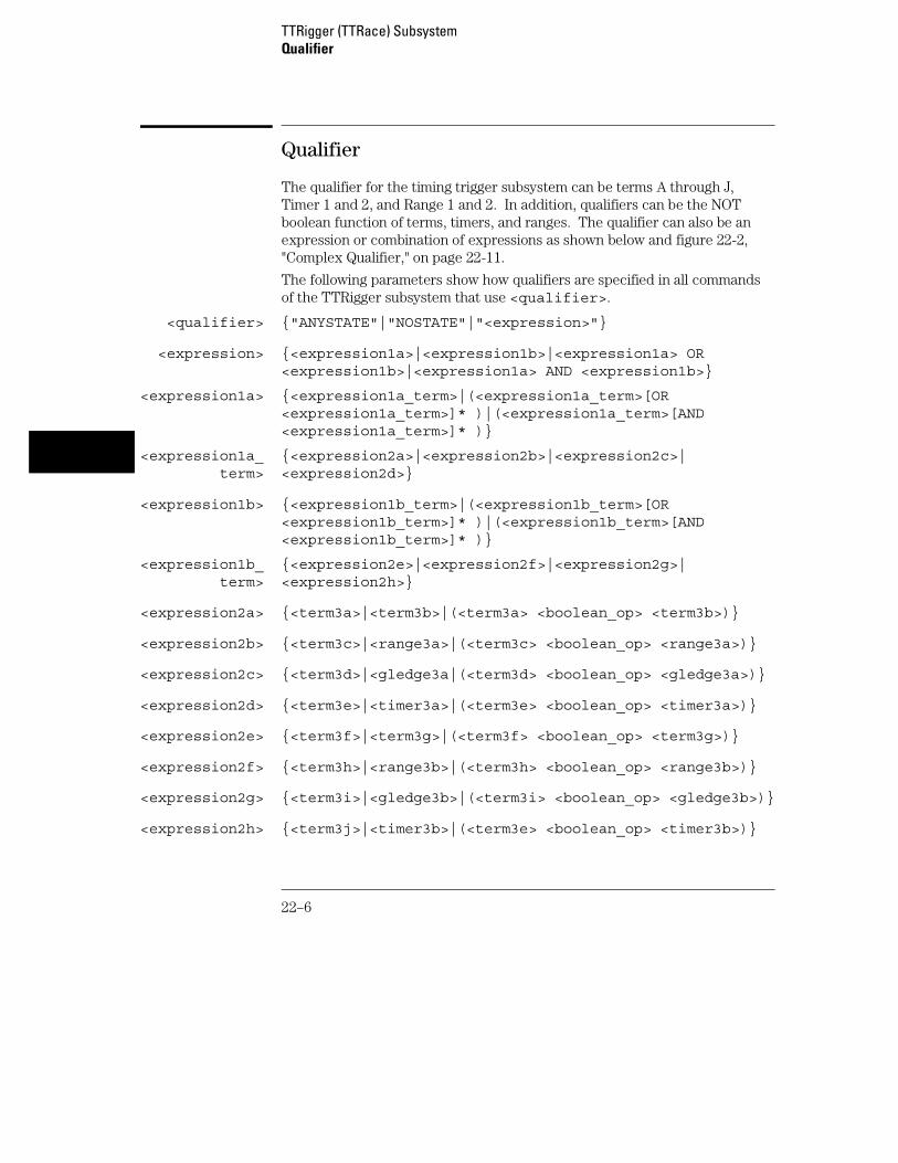
Qualifier
The qualifier for the timing trigger subsystem can be terms A through J,Timer 1 and 2, and Range 1 and 2. In addition, qualifiers can be the NOTboolean function of terms, timers, and ranges. The qualifier can also be anexpression or combination of expressions as shown below and figure 22-2,"Complex Qualifier," on page 22-11.
The following parameters show how qualifiers are specified in all commandsof the TTRigger subsystem that use <qualifier>.
<qualifier> {"ANYSTATE"|"NOSTATE"|"<expression>"}
<expression> {<expression1a>|<expression1b>|<expression1a> OR<expression1b>|<expression1a> AND <expression1b>}
<expression1a> {<expression1a_term>|(<expression1a_term>[OR<expression1a_term>]* )|(<expression1a_term>[AND<expression1a_term>]* )}
<expression1a_term>
{<expression2a>|<expression2b>|<expression2c>|<expression2d>}
<expression1b> {<expression1b_term>|(<expression1b_term>[OR<expression1b_term>]* )|(<expression1b_term>[AND<expression1b_term>]* )}
<expression1b_term>
{<expression2e>|<expression2f>|<expression2g>|<expression2h>}
<expression2a> {<term3a>|<term3b>|(<term3a> <boolean_op> <term3b>)}
<expression2b> {<term3c>|<range3a>|(<term3c> <boolean_op> <range3a>)}
<expression2c> {<term3d>|<gledge3a|(<term3d> <boolean_op> <gledge3a>)}
<expression2d> {<term3e>|<timer3a>|(<term3e> <boolean_op> <timer3a>)}
<expression2e> {<term3f>|<term3g>|(<term3f> <boolean_op> <term3g>)}
<expression2f> {<term3h>|<range3b>|(<term3h> <boolean_op> <range3b>)}
<expression2g> {<term3i>|<gledge3b>|(<term3i> <boolean_op> <gledge3b>)}
<expression2h> {<term3j>|<timer3b>|(<term3e> <boolean_op> <timer3b>)}
TTRigger (TTRace) SubsystemQualifier
22–6

<boolean_op> {AND|NAND|OR|NOR|XOR|NXOR}
<term3a> {A|NOTA}
<term3b> {B|NOTB}
<term3c> {C|NOTC}
<term3d> {D|NOTD}
<term3e> {E|NOTE}
<term3f> {F|NOTF}
<term3g> {G|NOTG}
<term3h> {H|NOTH}
<term3i> {I|NOTI}
<term3j> {J|NOTJ}
<range3a> {IN_RANGE1|OUT_RANGE1}
<range3b> {IN_RANGE2|OUT_RANGE2}
<gledge3a> {GLEDge1|NOT GLEDge1}
<gledge3b> {GLEDge2|NOT GLEDge2}
<timer3a> {TIMER1<|TIMER1>}
<timer3b> {TIMER2<|TIMER2>}
* = is optional such that it can be used zero or more times+ = must be used at least once and can be repeated
TTRigger (TTRace) SubsystemQualifier
22–7

Qualifier Rules
The following rules apply to qualifiers:
• Qualifiers are quoted strings and, therefore, need quotes.
• Expressions are evaluated from left to right.
• Parenthesis are used to change the order evaluation and, therefore, areoptional.
• An expression must map into the combination logic presented in thecombination pop-up menu within the TTRigger menu.
Examples ’A’’( A OR B )’’(( A OR B ) AND C )’’(( A OR B ) AND C AND IN_RANGE2 )’’(( A OR B ) AND ( C AND IN_RANGE1 ))’’IN_RANGE1 AND ( A OR B ) AND C’
TTRigger (TTRace)
Selector :MACHine{1|2}:TTRigger
The TTRigger (TTRace) (Trace Trigger) selector is used as a part of acompound header to access the settings found in the Timing Trace menu. Italways follows the MACHine selector because it selects a branch directlybelow the MACHine level in the command tree.
Example OUTPUT XXX;":MACHINE1:TTRIGGER:TAG TIME"
TTRigger (TTRace) SubsystemTTRigger (TTRace)
22–8

ACQuisition
Command :MACHine{1|2}:TTRigger:ACQuisition{AUTOmatic|MANual}
The ACQuisition command allows you to specify the acquisition mode for theTiming analyzer.
Example OUTPUT XXX;":MACHINE1:TTRIGGER:ACQUISITION AUTOMATIC"
Query :MACHine{1|2}:TTRigger:ACQuisition?
The ACQuisition query returns the current acquisition mode specified.Returned Format [:MACHine{1|2}:TTRigger:ACQuisition] {AUTOmatic|MANual}<NL>
Example OUTPUT XXX;":MACHINE1:TTRIGGER:ACQUISITION?"
BRANch
Command :MACHine{1|2}:TTRigger:BRANch<N><branch_qualifier>,<to_level_number>
The BRANch command defines the branch qualifier for a given sequencelevel. When this branch qualifier is matched, it will cause the sequencerto jump to the specified sequence level.
The terms used by the branch qualifier (A through J) are defined by theTERM command. The meaning of IN_RANGE and OUT_RANGE isdetermined by the RANGE command.
Within the limitations shown by the syntax definitions, complex expressionsmay be formed using the AND and OR operators. Expressions are limited towhat you could manually enter through the Timing Trigger menu. Regardingparentheses, the syntax definitions on the next page show only the requiredones. Additional parentheses are allowed as long as the meaning of the
TTRigger (TTRace) SubsystemACQuisition
22–9

expression is not changed. Figure 22-2, on page 22-11 shows a complexexpression as seen in the Timing Trigger menu.
Example The following statements are all correct and have the same meaning. Noticethat the conventional rules for precedence are not followed. The expressionsare evaluated from left to right.OUTPUT XXX;":MACHINE1:TTRIGGER:BRANCH1 ’C AND D OR F OR G’, 1"OUTPUT XXX;":MACHINE1:TTRIGGER:BRANCH1 ’((C AND D) OR (F ORG))’, 1"OUTPUT XXX;":MACHINE1:TTRIGGER:BRANCH1 ’F OR (C AND D) ORG’,1"
<N> integer from 1 to <number_of_levels>
<to_level_number>
integer from 1 to <number_of_levels>
<number_of_levels>
integer from 1 to the number of existing sequence levels (maximum 10)
<branch_qualifier>
<qualifier> see "Qualifier" on page 22-6
Examples OUTPUT XXX;":MACHINE1:TTRIGGER:BRANCH1 ’ANYSTATE’, 3"OUTPUT XXX;":MACHINE2:TTRIGGER:BRANCH2 ’A’, 7"OUTPUT XXX;":MACHINE1:TTRIGGER:BRANCH3 ’((A OR B) OR NOTG)’,1"
TTRigger (TTRace) SubsystemBRANch
22–10

Query Syntax :MACHine{1|2}:TTRigger:BRANch<N>?
The BRANch query returns the current branch qualifier specification for agiven sequence level.
Returned Format [:MACHine{1|2}:TTRigger:BRANch<N>] <branch_qualifier>,<to_level_num><NL>
Example OUTPUT XXX;":MACHINE1:TTRIGGER:BRANCH3?"
Figure 22-2
Complex Qualifier
Figure 22-2 is a front-panel representation of the complex qualifier (a ORb) And (g OR h).
Example This example would be used to specify this complex qualifier.
OUTPUT XXX;":MACHINE1:TTRIGGER:BRANCH1 ’((A OR B) AND(G OR H))’, 2"
TTRigger (TTRace) SubsystemBRANch
22–11

Terms A through E, RANGE 1, GLITCH/EDGE1, and TIMER 1 must be groupedtogether and terms F through J, RANGE 2, GLITCH/EDGE2, and TIMER 2 must begrouped together. In the first level, terms from one group may not be mixedwith terms from the other. For example, the expression ((A OR IN_RANGE2)AND (C OR H)) is not allowed because the term C cannot be specified in the Ethrough J group.
In the first level, the operators you can use are AND, NAND, OR, NOR,XOR, NXOR. Either AND or OR may be used at the second level to join thetwo groups together. It is acceptable for a group to consist of a single term.Thus, an expression like (B AND G) is legal since the two operands are bothsimple terms from separate groups.
CLEar
Command :MACHine{1|2}:TTRigger:CLEar{All|SEQuence|RESource}
The CLEar command allows you to clear all settings in the Timing Triggermenu and replace them with the default, clear only the sequence levels, orclear only the resource term patterns.
Example OUTPUT XXX;":MACHINE1:TTRIGGER:CLEAR RESOURCE"
TTRigger (TTRace) SubsystemCLEar
22–12

FIND
Command :MACHine{1|2}:TTRigger:FIND<N><time_qualifier>,<condition_mode>
The FIND command defines the time qualifier for a given sequence level.The qualifier tells the timing analyzer when to proceed to the next sequencelevel. When this proceed qualifier is matched the specified number of times,the sequencer will proceed to the next sequence level. In the sequence levelwhere the trigger is specified, the FIND command specifies the triggerqualifier (see SEQuence command).
The terms A through J are defined by the TERM command. The meaning ofIN_RANGE and OUT_RANGE is determined by the RANGe command.Expressions are limited to what you could manually enter through the TimingTrigger menu. Regarding parentheses, the syntax definitions below showonly the required ones. Additional parentheses are allowed as long as themeaning of the expression is not changed. See figure 12-2 on page 12-11 fora detailed example.
<N> integer from 1 to the number of existing sequence levels (maximum 10)
<condition_mode>
{{GT|LT}, <duration_time>|OCCurrence, <occurrence>}
GT greater than
LT less than
<duration_time> real number from 8 ns to 5.00 seconds depending on sample period
<occurrence> integer from 1 to 1048575
<time_qualifier>
<qualifier> see "Qualifier" on page 22-6
Examples OUTPUT XXX;":MACHINE1:TTRIGGER:FIND1 ’ANYSTATE’, GT, 10E−6"OUTPUT XXX;":MACHINE1:TTRIGGER:FIND3 ’((NOTA AND NOTB) ORG)’, OCCURRENCE, 10"
TTRigger (TTRace) SubsystemFIND
22–13

Query :MACHine{1|2}:TTRigger:FIND4?
The FIND query returns the current time qualifier specification for a givensequence level.
Returned Format [:MACHine{1|2}:TTRigger:FIND<N>] <condition_mode>,<occurrence><NL>
Example OUTPUT XXX;":MACHINE1:TTRIGGER:FIND<N>?"
GLEDge
Command :MACHine{1|2}:TTRigger:GLEDge<N> <label_name>,<glitch_edge_spec>
The GLEDge (glitch/edge) command allows you to define edge and glitchspecifications for a given label. Edge specifications can be R (rising), F(falling), E (either), or "." (don’t care). Glitch specifications consist of G(glitch) or "." (don’t care). Edges and glitches are sent in the same stringwith the right most string character specifying what the right most bit will be.
The <glitch_edge_spec> string length must match the exact number of bitsassigned to the specified label. If the string length does not match the numberof bits, the "Parameter string invalid" message is displayed.
<N> {1|2}
<label_name> string of up to 6 alphanumeric characters
<glitch_edge_spec>
string consisting of {R|F|E|G|.| [to total number of bits]}
TTRigger (TTRace) SubsystemGLEDge
22–14

Example For 8 bits assigned and no glitch:
OUTPUT XXX;":MACHINE1:TTRIGGER:GLEDGE1 ’DATA’, ’....F..E’"
For 16 bits assigned with glitch:OUTPUT XXX;":MACHINE1:TTRIGGER:GLEDGE1 ’DATA’,’....GGG.....F..R’"
Query :MACHine{1|2}:TTRigger:GLEDe<N>? <label_name>
The GLEDge query returns the current specification for the given label.Returned Format [:MACHine{1|2}:TTRigger:GLEDe<N>]
<label_name>,<glitch_edge_pattern><NL>
Example OUTPUT XXX;":MACHINE1:TTRIGGER:GLEDGE1? ’DATA’"
RANGe
Command :MACHine{1|2}:TTRigger:RANGE <label_name>,<start_pattern>,<stop_pattern>
The RANGe command allows you to specify a range recognizer term for thespecified machine. Since a range can only be defined across one label and,since a label must contain 32 or less bits, the value of the start pattern or stoppattern will be between (232)−1 and 0.
Since a label can only be defined across a maximum of two pods, a range termis only available across a single label; therefore, the end points of the rangecannot be split between labels.
When these values are expressed in binary, they represent the bit values forthe label at one of the range recognizers’ end points. Don’t cares are notallowed in the end point pattern specifications.
TTRigger (TTRace) SubsystemRANGe
22–15

<label_name> string of up to 6 alphanumeric characters
<start_pattern> "{#B{0|1} . . . |#Q{0|1|2|3|4|5|6|7} . . . |#H{0|1|2|3|4|5|6|7|8|9|A|B|C|D|E|F} . . . |{0|1|2|3|4|5|6|7|8|9} . . . }"
<stop_pattern> "{#B{0|1} . . . |#Q{0|1|2|3|4|5|6|7} . . . |#H{0|1|2|3|4|5|6|7|8|9|A|B|C|D|E|F} . . . |{0|1|2|3|4|5|6|7|8|9} . . . }"
Examples OUTPUT XXX;":MACHINE1:TTRIGGER:RANGE ’DATA’, ’127’, ’255’ "OUTPUT XXX;":MACHINE1:TTRIGGER:RANGE ’ABC’, ’#B00001111’,’#HCF’ "
Query :MACHine{1|2}:TTRigger:RANGe?
The RANGe query returns the range recognizer end point specifications forthe range.
Returned Format [:MACHine{1|2}:STRAce:RANGe] <label_name>,<start_pattern>,<stop_pattern><NL>
Example OUTPUT XXX;":MACHINE1:TTRIGGER:RANGE?"
TTRigger (TTRace) SubsystemRANGe
22–16
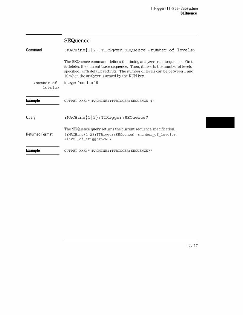
SEQuence
Command :MACHine{1|2}:TTRigger:SEQuence <number_of_levels>
The SEQuence command defines the timing analyzer trace sequence. First,it deletes the current trace sequence. Then, it inserts the number of levelsspecified, with default settings. The number of levels can be between 1 and10 when the analyzer is armed by the RUN key.
<number_of_levels>
integer from 1 to 10
Example OUTPUT XXX;":MACHINE1:TTRIGGER:SEQUENCE 4"
Query :MACHine{1|2}:TTRigger:SEQuence?
The SEQuence query returns the current sequence specification.Returned Format [:MACHine{1|2}:TTRigger:SEQuence] <number_of_levels>,
<level_of_trigger><NL>
Example OUTPUT XXX;":MACHINE1:TTRIGGER:SEQUENCE?"
TTRigger (TTRace) SubsystemSEQuence
22–17

SPERiod
Command :MACHine{1|2}:TTRigger:SPERiod <sample_period>
The SPERiod command allows you to set the sample period of the timinganalyzer in the Conventional and Glitch modes. The sample period rangedepends on the mode selected and is as follows:
• 2 ns to 8 ms for Conventional Half Channel 500 MHz
• 4 ns to 8 ms for Conventional Full Channel 250 MHz
• 4 ns for Transitional Half Channel
• 8 ns for Transitional Full Channel
• 8 ns to 8 ms for Glitch Half Channel 125 MHz
<sample_period> real number from 2 ns to 8 ms depending on mode
Example OUTPUT XXX;":MACHINE1:TTRIGGER:SPERIOD 50E−9"
Query :MACHine{1|2}:TTRigger:SPERiod?
The SPERiod query returns the current sample period.Returned Format [:MACHine{1|2}:TTRigger:SPERiod] <sample_period><NL>
<sample_period> real number from 2 ns to 8 ms depending on mode
Example OUTPUT XXX;":MACHINE1:TTRIGGER:SPERIOD?"
TTRigger (TTRace) SubsystemSPERiod
22–18
TCONtrol
Command :MACHine{1|2}:TTRigger:TCONtrol<N> <timer_num>,{OFF|STARt|PAUSe|CONTinue}
The TCONtrol (timer control) command allows you to turn off, start, pause,or continue the timer for the specified level. The time value of the timer isdefined by the TIMER command.
<N> integer from 1 to the number of existing sequence levels (maximum 10)
<timer_num> {1|2}
Example OUTPUT XXX;":MACHINE2:TTRIGGER:TCONTROL6 1, PAUSE"
Query :MACHine{1|2}:TTRigger:TCONTROL<N>? <timer_num>
The TCONtrol query returns the current TCONtrol setting of the specifiedlevel.
Returned Format [:MACHine{1|2}:TTRigger:TCONTROL<N> <timer_num>]{OFF|STARt|PAUSe|CONTinue}<NL>
Example OUTPUT XXX;":MACHINE2:TTRIGGER:TCONTROL6? 1"
TTRigger (TTRace) SubsystemTCONtrol
22–19
TERM
Command :MACHine{1|2}:TTRigger:TERM<term_id>,<label_name>,<pattern>
The TERM command allows you to a specify a pattern recognizer term in thespecified machine. Each command deals with only one label in the giventerm; therefore, a complete specification could require several commands.Since a label can contain 32 or less bits, the range of the pattern value will bebetween 232 − 1 and 0. When the value of a pattern is expressed in binary, itrepresents the bit values for the label inside the pattern recognizer term.Since the pattern parameter may contain don’t cares and be represented inseveral bases, it is handled as a string of characters rather than a number.
All 10 terms (A through J) are available to either machine but not bothsimultaneously. If you send the TERM command to a machine with a termthat has not been assigned to that machine, an error message "Legalcommand but settings conflict" is returned.
<term_id> {A|B|C|D|E|F|G|H|I|J}
<label_name> string of up to 6 alphanumeric characters
<pattern> "{#B{0|1|X} . . . |#Q{0|1|2|3|4|5|6|7|X} . . . |#H{0|1|2|3|4|5|6|7|8|9|A|B|C|D|E|F|X} . . . |{0|1|2|3|4|5|6|7|8|9} . . . }"
Example OUTPUT XXX;":MACHINE1:TTRIGGER:TERM A,’DATA’,’255’ "OUTPUT XXX;":MACHINE1:TTRIGGER:TERM B,’ABC’,’#BXXXX1101’ "
TTRigger (TTRace) SubsystemTERM
22–20

Query :MACHine{1|2}:TTRigger:TERM?<term_id>,<label_name>
The TERM query returns the specification of the term specified by termidentification and label name.
Returned Format [:MACHine{1|2}:STRAce:TERM] <term_id>,<label_name>,<pattern><NL>
Example OUTPUT XXX;":MACHINE1:TTRIGGER:TERM? B,’DATA’ "
TIMER
Command :MACHine{1|2}:TTRigger:TIMER{1|2} <time_value>
The TIMER command sets the time value for the specified timer. The limitsof the timer are 400 ns to 500 seconds in 16 ns to 500 µs increments. Theincrement value varies with the time value of the specified timer.
<time_value> real number from 400 ns to 500 seconds in increments which vary from 16 nsto 500 µs.
Example OUTPUT XXX;":MACHINE1:TTRIGGER:TIMER1 100E−6"
Query :MACHine{1|2}:TTRigger:TIMER{1|2}?
The TIMER query returns the current time value for the specified timer.Returned Format [:MACHine{1|2}:TTRigger:TIMER{1|2}] <time_value><NL>
Example OUTPUT XXX;":MACHINE1:TTRIGGER:TIMER1?"
TTRigger (TTRace) SubsystemTIMER
22–21

TPOSition
Command :MACHine{1|2}:TTRigger:TPOSition{STARt|CENTer|END|DELay, <time_val>|POSTstore,<poststore>}
The TPOSition (trigger position) command allows you to set the trigger atthe start, center, end or at any position in the trace (poststore). Poststore isdefined as 0 to 100 percent with a poststore of 100 percent being the same asstart position and a poststore 0 percent being the same as an end trace.
<time_val> real number from either (2 × sample period) or 16 ns whichever is greater to(1048575 × sample period).
<poststore> integer from 0 to 100 representing percentage of poststore.
Examples OUTPUT XXX;":MACHINE1:TTRIGGER:TPOSITION END"OUTPUT XXX;":MACHINE1:TTRIGGER:TPOSITION POSTstore,75"
Query :MACHine{1|2}:TTRigger:TPOSition?
The TPOSition query returns the current trigger position setting.Returned Format [:MACHine{1|2}:TTRigger:TPOSition] {STARt|CENTer|END|DELay,
<time_val>|POSTstore,<poststore>}<NL>
Example OUTPUT XXX;":MACHINE1:TTRIGGER:TPOSITION?"
TTRigger (TTRace) SubsystemTPOSition
22–22

23
TWAVeform Subsystem

Introduction
The TWAVeform subsystem contains the commands available for theTiming Waveforms menu in the 1660-series logic analyzer. Thesecommands are:
• ACCumulate • REMove• ACQuisition • RUNTil• CENter • SPERiod• CLRPattern • TAVerage• CLRStat • TMAXimum• DELay • TMINimum• INSert • TPOSition• MMODe • VRUNs• OCONdition • XCONdition• OPATtern • XOTime• OSEarch • XPATtern• OTIMe • XSEarch• RANGe • XTIMe
23–2

Figure 23-1
TWAVeform Subsystem Syntax Diagram
TWAVeform Subsystem
23–3

Figure 23-1 (continued)
TWAVeform Subsystem Syntax Diagram (continued)
TWAVeform Subsystem
23–4

Figure 23-1 (continued)
TWAVeform Subsystem Syntax Diagram (continued)
TWAVeform Subsystem
23–5

Table 23-1 TWAVeform Parameter Values
Parameter Value
delay_value real number between −2500 s and +2500 s
module_spec {1|2|3|4|5|6|7|8|9|10} 2 through 10 unused
bit_id integer from 0 to 31
waveform string containing <acquisition_spec>{1|2}
acquisition_spec {A|B|C|D|E|F|G|H|I|J} (slot where acquisition card is located)
label_name string of up to 6 alphanumeric characters
label_pattern "{#B{0|1|X} . . . |#Q{0|1|2|3|4|5|6|7|X}...|#H{0|1|2|3|4|5|6|7|8|9|A|C|D|E|F|X}...|{0|1|2|3|4|5|6|7|8|9|X}...}"
occurrence integer
time_value real number
label_id string of one alpha and one numeric character
module_num slot number in which the time base card is installed
time_range real number between 10 ns and 10 ks
run_until_spec {OFF|LT,<value>|GT,<value>|INRange<value>,<value>|OUTRange<value>,<value>}
GT greater than
LT less than
value real number
time_val real number from 0 to 500 representing seconds
TWAVeform Subsystem
23–6

TWAVeform
Selector :MACHine{1|2}:TWAVeform
The TWAVeform selector is used as part of a compound header to access thesettings found in the Timing Waveforms menu. It always follows theMACHine selector because it selects a branch below the MACHine level in thecommand tree.
Example OUTPUT XXX;":MACHINE1:TWAVEFORM:DELAY 100E−9"
ACCumulate
Command :MACHine{1|2}:TWAVeform:ACCumulate <setting>
The ACCumulate command allows you to control whether the chart displaygets erased between each individual run or whether subsequent waveformsare allowed to be displayed over the previous ones.
<setting> {0|OFF} or {1|ON}
Example OUTPUT XXX;":MACHINE1:TWAVEFORM:ACCUMULATE ON"
Query :MACHine{1|2}:TWAVeform:ACCumulate?
The ACCumulate query returns the current setting. The query always showsthe setting as the characters, "0" (off) or "1" (on).
Returned Format [:MACHine{1|2}:TWAVeform:ACCumulate] {0|1}<NL>
Example OUTPUT XXX;":MACHINE1:TWAVEFORM:ACCUMULATE?"
TWAVeform SubsystemTWAVeform
23–7

ACQuisition
Command :MACHine{1|2}:TWAVeform:ACQuisition{AUTOmatic|MANual}
The ACQuisition command allows you to specify the acquisition mode for thestate analyzer. The acquisition modes are automatic and manual.
Example OUTPUT XXX;":MACHINE2:TWAVEFORM:ACQUISITION AUTOMATIC"
Query MACHine{1|2}:TWAVeform:ACQuisition?
The ACQuisition query returns the current acquisition mode.Returned Format [:MACHine{1|2}:TWAVeform:ACQuisition] {AUTOmatic|MANual}<NL>
Example OUTPUT XXX;":MACHINE2:TWAVEFORM:ACQUISITION?"
CENTer
Command :MACHine{1|2}:Twaveform:CENTer <marker_type>
The CENTer command allows you to center the waveform display about thespecified markers.
<marker_type> {X|O|XO|TRIGger}
Example OUTPUT XXX;":MACHINE1:TWAVEFORM:CENTER X"
TWAVeform SubsystemACQuisition
23–8

CLRPattern
Command :MACHine{1|2}:TWAVeform:CLRPattern {X|O|ALL}
The CLRPattern command allows you to clear the patterns in the selectedSpecify Patterns menu.
Example OUTPUT XXX;":MACHINE1:TWAVEFORM:CLRPATTERN ALL"
CLRStat
Command :MACHine{1|2}:Twaveform:CLRStat
The CLRStat command allows you to clear the waveform statistics withouthaving to stop and restart the acquisition.
Example OUTPUT XXX;":MACHINE1:TWAVEFORM:CLRSTAT"
DELay
Command :MACHine{1|2}:TWAVeform:DELay <delay_value>
The DELay command specifies the amount of time between the timingtrigger and the horizontal center of the the timing waveform display. Theallowable values for delay are −2500 s to +2500 s. If the acquisition mode isautomatic, then in glitch acquisition mode, as delay becomes large in anabsolute sense, the sample rate is adjusted so that data will be acquired inthe time window of interest. In transitional acquisition mode, data may notfall in the time window since the sample period is fixed and the amount oftime covered in memory is dependent on how frequent the input signaltransitions occur.
TWAVeform SubsystemCLRPattern
23–9

<delay_value> real number between −2500 s and +2500 s
Example OUTPUT XXX;":MACHINE1:TWAVEFORM:DELAY 100E−6"
Query :MACHine{1|2}:TWAVeform:DELay?
The DELay query returns the current time offset (delay) value from thetrigger.
Returned Format [:MACHine{1|2}:TWAVeform:DELay] <delay_value><NL>
Example OUTPUT XXX;":MACHINE1:TWAVEFORM:DELAY?"
INSert
Command :MACHine{1|2}:TWAVeform:INSert [<module_spec>,]<label_name>[,{<bit_id>|OVERlay|ALL}]
The INSert command allows you to add waveforms to the state waveformdisplay. Waveforms are added from top to bottom on the screen. When 96waveforms are present, inserting additional waveforms replaces the lastwaveform. Bit numbers are zero based, so a label with 8 bits is referenced asbits 0 through 7. Specifying OVERlay causes a composite waveform displayof all bits or channels for the specified label. If you do not specify the thirdparameter, ALL is assumed.
<module_spec> {1|2|3|4|5|6|7|8|9|10} 2 through 10 unused.
<label_name> string of up to 6 alphanumeric characters
<bit_id> integer from 0 to 31
Example OUTPUT XXX;":MACHINE1:TWAVEFORM:INSERT 1, ’WAVE’,10"
TWAVeform SubsystemINSert
23–10

MMODe
Command :MACHine{1|2}:TWAVeform:MMODe{OFF|PATTern|TIME|MSTats}
The MMODe (Marker Mode) command selects the mode controlling markermovement and the display of the marker readouts. When PATTern isselected, the markers will be placed on patterns. When TIME is selected, themarkers move on time. In MSTats, the markers are placed on patterns, butthe readouts will be time statistics.
Example OUTPUT XXX; ":MACHINE1:TWAVEFORM:MMODE TIME"
Query :MACHine{1|2}:TWAVeform:MMODe?
The MMODe query returns the current marker mode.Returned Format [:MACHine{1|2}:TWAVeform:MMODe] <marker_mode><NL>
<marker_mode> {OFF|PATTern|TIME|MSTats}
Example OUTPUT XXX;":MACHINE1:TWAVEFORM:MMODE?"
TWAVeform SubsystemMMODe
23–11

OCONdition
Command :MACHine{1|2}:TWAVeform:OCONdition{ENTering|EXITing}
The OCONdition command specifies where the O marker is placed. The Omarker can be placed on the entry or exit point of the OPATtern when in thePATTern marker mode.
Example OUTPUT XXX; ":MACHINE1:TWAVEFORM:OCONDITION ENTERING"
Query :MACHine{1|2}:TWAVeform:OCONdition?
The OCONdition query returns the current setting.Returned Format [:MACHine{1|2}:TWAVeform:OCONdition] {ENTering|EXITing}<NL>
Example OUTPUT XXX;":MACHINE1:TWAVEFORM:OCONDITION?"
TWAVeform SubsystemOCONdition
23–12

OPATtern
Command :MACHine{1|2}:TWAVeform:OPATtern<label_name>,<label_pattern>
The OPATtern command allows you to construct a pattern recognizer termfor the O marker which is then used with the OSEarch criteria andOCONdition when moving the marker on patterns. Since this command dealswith only one label at a time, a complete specification could require severalinvocations.
When the value of a pattern is expressed in binary, it represents the bitvalues for the label inside the pattern recognizer term. In whatever base isused, the value must be between 0 and 232 − 1, since a label may not havemore than 32 bits. Because the <label_pattern> parameter may containdon’t cares, it is handled as a string of characters rather than a number.
<label_name> string of up to 6 alphanumeric characters
<label_pattern> "{#B{0|1|X} . . . |#Q{0|1|2|3|4|5|6|7|X} . . . |#H{0|1|2|3|4|5|6|7|8|9|A|B|C|D|E|F|X} . . . |{0|1|2|3|4|5|6|7|8|9} . . . }"
Example OUTPUT XXX; ":MACHINE1:TWAVEFORM:OPATTERN ’A’,’511’"
Query :MACHine{1|2}:TWAVeform:OPATtern? <label_name>
The OPATtern query, in pattern marker mode, returns the patternspecification for a given label name. In the time marker mode, the queryreturns the pattern under the O marker for a given label. If the O marker isnot placed on valid data, don’t cares (X) are returned.
Returned Format [:MACHine{1|2}:TWAVeform:OPATtern] <label_name>,<label_pattern><NL>
Example OUTPUT XXX;":MACHINE1:TWAVEFORM:OPATTERN? ’A’"
TWAVeform SubsystemOPATtern
23–13

OSEarch
Command :MACHine{1|2}:TWAVeform:OSEarch<occurrence>,<origin>
The OSEarch command defines the search criteria for the O marker which isthen used with the associated OPATtern recognizer specification and theOCONdition when moving markers on patterns. The origin parameter tellsthe marker to begin a search with the trigger or with the X marker. Theactual occurrence the marker searches for is determined by the occurrenceparameter of the OPATtern recognizer specification, relative to the origin.An occurrence of 0 places a marker on the selected origin. With a negativeoccurrence, the marker searches before the origin. With a positiveoccurrence, the marker searches after the origin.
<origin> {STARt|TRIGger|XMARker}
<occurrence> integer from −8192 to +8192
Example OUTPUT XXX; ":MACHINE1:TWAVEFORM:OSEARCH +10,TRIGGER"
Query :MACHine{1|2}:TWAVeform:OSEarch?
The OSEarch query returns the search criteria for the O marker.Returned Format [:MACHine{1|2}:TWAVeform:OSEarch] <occurrence>,<origin><NL>
Example OUTPUT XXX;":MACHINE1:TWAVEFORM:OSEARCH?"
TWAVeform SubsystemOSEarch
23–14

OTIMe
Command :MACHine{1|2}:TWAVeform:OTIMe <time_value>
The OTIMe command positions the O marker in time when the marker modeis TIME. If data is not valid, the command performs no action.
<time_value> real number −2.5 ks to +2.5 ks
Example OUTPUT XXX; ":MACHINE1:TWAVEFORM:OTIME 30.0E−6"
Query :MACHine{1|2}:TWAVeform:OTIMe?
The OTIMe query returns the O marker position in time. If data is not valid,the query returns 9.9E37.
Returned Format [:MACHine{1|2}:TWAVeform:OTIMe] <time_value><NL>
Example OUTPUT XXX;":MACHINE1:TWAVEFORM:OTIME?"
TWAVeform SubsystemOTIMe
23–15

RANGe
Command :MACHine{1|2}:TWAVeform:RANGe <time_value>
The RANGe command specifies the full-screen time in the timing waveformmenu. It is equivalent to ten times the seconds-per-division setting on thedisplay. The allowable values for RANGe are from 10 ns to 10 ks.
<time_range> real number between 10 ns and 10 ks
Example OUTPUT XXX;":MACHINE1:TWAVEFORM:RANGE 100E−9"
Query :MACHine{1|2}:TWAVeform:RANGe?
The RANGe query returns the current full-screen time.Returned Format [:MACHine{1|2}:TWAVeform:RANGe] <time_value><NL>
Example OUTPUT XXX;":MACHINE1:TWAVEFORM:RANGE?"
REMove
Command :MACHine{1|2}:TWAVeform:REMove
The REMove command deletes all waveforms from the display.
Example OUTPUT XXX;":MACHINE1:TWAVEFORM:REMOVE"
TWAVeform SubsystemRANGe
23–16

RUNTil
Command :MACHine{1|2}:TWAVeform:RUNTil <run_until_spec>
The RUNTil (run until) command defines stop criteria based on the timebetween the X and O markers when the trace mode is in repetitive. WhenOFF is selected, the analyzer will run until either the STOP touch screen fieldis touched, or, the STOP command is sent. Run until time between X and Omarker options are:
• Less Than (LT) a specified time value.
• Greater Than (GT) a specified time value.
• In the range (INRange) between two time values.
• Out of the range (OUTRange) between two time values
End points for the INRange and OUTRange should be at least 2 ns apart sincethis is the minimum time at which data is sampled.
This command affects the timing analyzer only, and has no relation to theRUNTil commands in the SLISt and COMPare subsystems.
<run_until_spec>
{OFF|LT,<value>|GT,<value>|INRange<value>,<value>|OUTRange<value>,<value>}
<value> real number
Examples OUTPUT XXX;":MACHINE1:TWAVEFORM:RUNTIL GT, 800.0E−6"OUTPUT XXX;":MACHINE1:TWAVEFORM:RUNTIL INRANGE, 4.5, 5.5"
Query :MACHine{1|2}:TWAVeform:RUNTil?
The RUNTil query returns the current stop criteria.Returned Format [:MACHine{1|2}:TWAVeform:RUNTil] <run_until_spec><NL>
Example OUTPUT XXX;":MACHINE1:TWAVEFORM:RUNTIL?"
TWAVeform SubsystemRUNTil
23–17

SPERiod
Command :MACHine{1|2}:TWAVeform:SPERiod <sample_period>
The SPERiod command allows you to set the sample period of the timinganalyzer in the Conventional and Glitch modes. The sample period rangedepends on the mode selected and is as follows:
• 2 ns to 8 ms for Conventional Half Channel 500 MHz
• 4 ns to 8 ms for Conventional Full Channel 250 MHz
• 8 ns to 8 ms for Glitch Half Channel 125 MHz
<sample_period> real number from 2 ns to 8 ms depending on mode
Example OUTPUT XXX;":MACHINE1:TWAVEFORM:SPERIOD 50E−9"
Query :MACHine{1|2}:TWAVeform:SPERiod?
The SPERiod query returns the current sample period.Returned Format [:MACHine{1|2}:TWAVeform:SPERiod] <sample_period><NL>
Example OUTPUT XXX;":MACHINE1:TWAVEFORM:SPERIOD?"
TWAVeform SubsystemSPERiod
23–18
TAVerage
Query :MACHine{1|2}:TWAVeform:TAVerage?
The TAVerage query returns the value of the average time between theX and O markers. If there is no valid data, the query returns 9.9E37.
Returned Format [:MACHine{1|2}:TWAVeform:TAVerage] <time_value><NL>
<time_value> real number
Example OUTPUT XXX;":MACHINE1:TWAVEFORM:TAVERAGE?"
TMAXimum
Query :MACHine{1|2}:TWAVeform:TMAXimum?
The TMAXimum query returns the value of the maximum time between the Xand O markers. If there is no valid data, the query returns 9.9E37.
Returned Format [:MACHine{1|2}:TWAVeform:TMAXimum] <time_value><NL>
<time_value> real number
Example OUTPUT XXX;":MACHINE1:TWAVEFORM:TMAXIMUM?"
TWAVeform SubsystemTAVerage
23–19

TMINimum
Query :MACHine{1|2}:TWAVeform:TMINimum?
The TMINimum query returns the value of the minimum time between the Xand O markers. If there is no valid data, the query returns 9.9E37.
Returned Format [:MACHine{1|2}:TWAVeform:TMINimum] <time_value><NL>
<time_value> real number
Example OUTPUT XXX;":MACHINE1:TWAVEFORM:TMINIMUM?"
TPOSition
Command :MACHine{1|2}:TWAVeform:TPOSition{STARt|CENTer|END|DELay,<time_val>|POSTstore,<percent>}
The TPOSition command allows you to control where the trigger point isplaced. The trigger point can be placed at the start, center, end, at apercentage of post store, or at a value specified by delay. The post storeoption is the same as the User Defined option when setting the triggerpoint from the front panel.
The TPOSition command is only available when the acquisition mode is set tomanual.
<time_val> real number from 0 to 500 seconds
<percent> integer from 1 to 100
Example OUTPUT XXX;":MACHINE2:TWAVEFORM:TPOSITION CENTER"
TWAVeform SubsystemTMINimum
23–20

Query :MACHine{1|2}:TWAVeform:TPOSition?
The TPOSition query returns the current trigger setting.Returned Format [:MACHine{1|2}:TWAVeform:TPOSition] {STARt|CENTer|END|DELay,
<time_val>|POSTstore,<percent>}<NL>
<time_val> real number from 0 to 500 seconds
Example OUTPUT XXX;":MACHINE2:TWAVEFORM:TPOSition?"
VRUNs
Query :MACHine{1|2}:TWAVeform:VRUNs?
The VRUNs query returns the number of valid runs and total number of runsmade. Valid runs are those where the pattern search for both the X and Omarkers was successful resulting in valid delta time measurements.
Returned Format [:MACHine{1|2}:TWAVeform:VRUNs] <valid_runs>,<total_runs><NL>
<valid_runs> zero or positive integer
<total_runs> zero or positive integer
Example OUTPUT XXX;":MACHINE1:TWAVEFORM:VRUNS?"
TWAVeform SubsystemVRUNs
23–21

XCONdition
Command :MACHine{1|2}:TWAVeform:XCONdition{ENTering|EXITing}
The XCONdition command specifies where the X marker is placed. The Xmarker can be placed on the entry or exit point of the XPATtern when in thePATTern marker mode.
Example OUTPUT XXX; ":MACHINE1:TWAVEFORM:XCONDITION ENTERING"
Query :MACHine{1|2}:TWAVeform:XCONdition?
The XCONdition query returns the current setting.Returned Format [:MACHine{1|2}:TWAVeform:XCONdition] {ENTering|EXITing}<NL>
Example OUTPUT XXX;":MACHINE1:TWAVEFORM:XCONDITION?"
XOTime
Query :MACHine{1|2}:TWAVeform:XOTime?
The XOTime query returns the time from the X marker to the O marker. Ifdata is not valid, the query returns 9.9E37.
Returned Format [:MACHine{1|2}:TWAVeform:XOTime] <time_value><NL>
<time_value> real number
Example OUTPUT XXX;":MACHINE1:TWAVEFORM:XOTIME?"
TWAVeform SubsystemXCONdition
23–22

XPATtern
Command :MACHine{1|2}:TWAVeform:XPATtern <label_name>,<label_pattern>
The XPATtern command allows you to construct a pattern recognizer termfor the X marker which is then used with the XSEarch criteria andXCONdition when moving the marker on patterns. Since this command dealswith only one label at a time, a complete specification could require severaliterations.
When the value of a pattern is expressed in binary, it represents the bitvalues for the label inside the pattern recognizer term. In whatever base isused, the value must be between 0 and 232 − 1, since a label may not havemore than 32 bits. Because the <label_pattern> parameter may containdon’t cares, it is handled as a string of characters rather than a number.
<label_name> string of up to 6 alphanumeric characters
<label_pattern> "{#B{0|1|X} . . . |#Q{0|1|2|3|4|5|6|7|X} . . . |#H{0|1|2|3|4|5|6|7|8|9|A|B|C|D|E|F|X} . . . |{0|1|2|3|4|5|6|7|8|9} . . . }"
Example OUTPUT XXX; ":MACHINE1:TWAVEFORM:XPATTERN ’A’,’511’"
Query :MACHine{1|2}:TWAVeform:XPATtern? <label_name>
The XPATtern query, in pattern marker mode, returns the patternspecification for a given label name. In the time marker mode, the queryreturns the pattern under the X marker for a given label. If the X marker isnot placed on valid data, don’t cares (X) are returned.
Returned Format [:MACHine{1|2}:TWAVeform:XPATtern] <label_name>,<label_pattern><NL>
Example OUTPUT XXX;":MACHINE1:TWAVEFORM:XPATTERN? ’A’"
TWAVeform SubsystemXPATtern
23–23

XSEarch
Command :MACHine{1|2}:TWAVeform:XSEarch<occurrence>,<origin>
The XSEarch command defines the search criteria for the X marker which isthen used with the associated XPATtern recognizer specification and theXCONdition when moving markers on patterns. The origin parameter tellsthe marker to begin a search with the trigger. The occurrence parameterdetermines which occurrence of the XPATtern recognizer specification,relative to the origin, the marker actually searches for. An occurrence of 0(zero) places a marker on the origin.
<origin> {TRIGger|STARt}
<occurrence> integer from −8192 to +8192
Example OUTPUT XXX; ":MACHINE1:TWAVEFORM:XSEARCH,+10,TRIGGER"
Query :MACHine{1|2}:TWAVeform:XSEarch?<occurrence>,<origin>
The XSEarch query returns the search criteria for the X marker.Returned Format [:MACHine{1|2}:TWAVeform:XSEarch] <occurrence>,<origin><NL>
Example OUTPUT XXX;":MACHINE1:TWAVEFORM:XSEARCH?"
TWAVeform SubsystemXSEarch
23–24

XTIMe
Command :MACHine{1|2}:TWAVeform:XTIMe <time_value>
The XTIMe command positions the X marker in time when the marker modeis TIME. If data is not valid, the command performs no action.
<time_value> real number from −2.5 ks to +2.5 ks
Example OUTPUT XXX; ":MACHINE1:TWAVEFORM:XTIME 40.0E−6"
Query :MACHine{1|2}:TWAVeform:XTIMe?
The XTIMe query returns the X marker position in time. If data is not valid,the query returns 9.9E37.
Returned Format [:MACHine{1|2}:TWAVeform:XTIMe] <time_value><NL>
Example OUTPUT XXX;":MACHINE1:TWAVEFORM:XTIME?"
TWAVeform SubsystemXTIMe
23–25

23–26

24
TLISt Subsystem

Introduction
The TLISt subsystem contains the commands available for the TimingListing menu in the 1660-series logic analyzers and is the same as theSLISt subsystem with the exception of the OCONdition andXCONdition commands. The TLISt subsystem commands are:
• COLumn
• CLRPattern
• DATA
• LINE
• MMODe
• OCONdition
• OPATtern
• OSEarch
• OSTate
• OTAG
• REMove
• RUNTil
• TAVerage
• TMAXimum
• TMINimum
• VRUNs
• XCONdition
• XOTag
• XOTime
• XPATtern
• XSEarch
• XSTate
• XTAG
24–2

Figure 24-1
TLISt Subsystem Syntax Diagram
TLISt Subsystem
24–3

Figure 24-1 (continued)
TLISt Subsystem Syntax Diagram (continued)
TLISt Subsystem
24–4

Figure 24-1 (continued)
TLISt Subsystem Syntax Diagram (continued)
TLISt Subsystem
24–5

Table 24-1 TLISt Parameter Values
Parameter Values
module_num {1|2|3|4|5|6|7|8|9|10} 2 through 10 not used
mach_num {1|2}
col_num integer from 1 to 61
line_number integer from −8191 to +8191
label_name string of up to 6 alphanumeric characters
base {BINary|HEXadecimal|OCTal|DECimal|TWOS|ASCii|SYMBol|IASSembler} for labels or{ABSolute|RELative} for tags
line_num_mid_screen integer from −8191to +8191
label_pattern "{#B{0|1|X} . . . |#Q{0|1|2|3|4|5|6|7|X} . . . |#H{0|1|2|3|4|5|6|7|8|9|A|B|C|D|E|F|X} . . .|{0|1|2|3|4|5|6|7|8|9} . . . }"
occurrence integer from −8191 to +8191
time_value real number
state_value real number
run_until_spec {OFF|LT,<value>|GT,<value>|INRange,<value>,<value>|OUTRange,<value>,<value>}
value real number
TLISt Subsystem
24–6
TLISt
Selector :MACHine{1|2}:TLISt
The TLISt selector is used as part of a compound header to access thosesettings normally found in the Timing Listing menu. It always follows theMACHine selector because it selects a branch directly below the MACHinelevel in the command tree.
Example OUTPUT XXX;":MACHINE1:TLIST:LINE 256"
COLumn
Command :MACHine{1|2}:TLISt:COLumn<col_num>[,<module_num>,MACHine{1|2}],<label_name>,<base>
The COLumn command allows you to configure the timing analyzerlist display by assigning a label name and base to one of the 61 verticalcolumns in the menu. A column number of 1 refers to the left most column.When a label is assigned to a column it replaces the original label in thatcolumn.
When the label name is "TAGS," the TAGS column is assumed and the nextparameter must specify RELative or ABSolute.
A label for tags must be assigned in order to use ABSolute or RELative statetagging.
TLISt SubsystemTLISt
24–7

<col_num> integer from 1 to 61
<module_num> {1|2|3|4|5|6|7|8|9|10} 2 through 10 unused
<label_name> a string of up to 6 alphanumeric characters
<base> {BINary|HEXadecimal|OCTal|DECimal|TWOS|ASCii|SYMBol|IASSembler} for labelsor{ABSolute|RELative} for tags
Example OUTPUT XXX;":MACHINE1:TLIST:COLUMN 4,1,’A’,HEX"
Query :MACHine{1|2}:TLISt:COLumn? <col_num>
The COLumn query returns the column number, label name, and base for thespecified column.
Returned Format [:MACHine{1|2}:TLISt:COLumn] <col_num>,<module_num>,MACHine{1|2},<label_name>,<base><NL>
Example OUTPUT XXX;":MACHINE1:TLIST:COLUMN? 4"
CLRPattern
Command :MACHine{1|2}:TLISt:CLRPattern {X|O|ALL}
The CLRPattern command allows you to clear the patterns in the selectedSpecify Patterns menu.
Example OUTPUT XXX;":MACHINE1:TLIST:CLRPATTERN O"
TLISt SubsystemCLRPattern
24–8

DATA
Query :MACHine{1|2}:TLISt:DATA? <line_number>,<label_name>
The DATA query returns the value at a specified line number for a givenlabel. The format will be the same as the one shown in the Listing display.
Returned Format [:MACHine{1|2}:TLISt:DATA] <line_number>,<label_name>,<pattern_string><NL>
<line_number> integer from −8191 to +8191
<label_name> string of up to 6 alphanumeric characters
<pattern_string>
"{#B{0|1|X} . . . |#Q{0|1|2|3|4|5|6|7|X} . . . |#H{0|1|2|3|4|5|6|7|8|9|A|B|C|D|E|F|X} . . . |{0|1|2|3|4|5|6|7|8|9} . . . }"
Example OUTPUT XXX;":MACHINE1:TLIST:DATA? 512, ’RAS’"
LINE
Command :MACHine{1|2}:TLISt:LINE <line_num_mid_screen>
The LINE command allows you to scroll the timing analyzer listing vertically.The command specifies the state line number relative to the trigger that theanalyzer highlights at the center of the screen.
<line_num_mid_screen>
integer from −8191 to +8191
Example OUTPUT XXX;":MACHINE1:TLIST:LINE 0"
TLISt SubsystemDATA
24–9
Query :MACHine{1|2}:TLISt:LINE?
The LINE query returns the line number for the state currently in the box atthe center of the screen.
Returned Format [:MACHine{1|2}:TLISt:LINE] <line_num_mid_screen><NL>
Example OUTPUT XXX;":MACHINE1:TLIST:LINE?"
MMODe
Command :MACHine{1|2}:TLISt:MMODe <marker_mode>
The MMODe command (Marker Mode) selects the mode controlling themarker movement and the display of marker readouts. When PATTern isselected, the markers will be placed on patterns. When TIME is selected, themarkers move on time between stored states. When MSTats is selected, themarkers are placed on patterns, but the readouts will be time statistics.
<marker_mode> {OFF|PATTern|TIME|MSTats}
Example OUTPUT XXX;":MACHINE1:TLIST:MMODE TIME"
Query :MACHine{1|2}:TLISt:MMODe?
The MMODe query returns the current marker mode selected.Returned Format [:MACHine{1|2}:TLISt:MMODe] <marker_mode><NL>
Example OUTPUT XXX;":MACHINE1:TLIST:MMODE?"
TLISt SubsystemMMODe
24–10

OCONdition
Command :MACHine{1|2}:TLISt:OCONdition {ENTering|EXITing}
The OCONdition command specifies where the O marker is placed. The Omarker can be placed on the entry or exit point of the OPATtern when in thePATTern marker mode.
Example OUTPUT XXX; ":MACHINE1:TLIST:OCONDITION ENTERING"
Query :MACHine{1|2}:TLISt:OCONdition?
The OCONdition query returns the current setting.Returned Format [:MACHine{1|2}:TLISt:OCONdition] {ENTering|EXITing}<NL>
Example OUTPUT XXX;":MACHINE1:TLIST:OCONDITION?"
OPATtern
Command :MACHine{1|2}:TLISt:OPATtern<label_name>,<label_pattern>
The OPATtern command allows you to construct a pattern recognizer termfor the O Marker which is then used with the OSEarch criteria when movingthe marker on patterns. Since this command deals with only one label at atime, a complete specification could require several iterations.
When the value of a pattern is expressed in binary, it represents the bitvalues for the label inside the pattern recognizer term. In whatever base isused, the value must be between 0 and 232 − 1, since a label may not havemore than 32 bits. Because the <label_pattern> parameter may contain don’tcares, it is handled as a string of characters rather than a number.
TLISt SubsystemOCONdition
24–11

<label_name> string of up to 6 alphanumeric characters
<label_pattern>
"{#B{0|1|X} . . . |#Q{0|1|2|3|4|5|6|7|X} . . . |#H{0|1|2|3|4|5|6|7|8|9|A|B|C|D|E|F|X} . . . |{0|1|2|3|4|5|6|7|8|9} . . . }"
Examples OUTPUT XXX;":MACHINE1:TLIST:OPATTERN ’DATA’,’255’ "OUTPUT XXX;":MACHINE1:TLIST:OPATTERN ’ABC’,’#BXXXX1101’ "
Query :MACHine{1|2}:TLISt:OPATtern? <label_name>
The OPATtern query returns the pattern specification for a given label name.Returned Format [:MACHine{1|2}:TLISt:OPATtern]
<label_name>,<label_pattern><NL>
Example OUTPUT XXX;":MACHINE1:TLIST:OPATTERN? ’A’"
OSEarch
Command :MACHine{1|2}:TLISt:OSEarch <occurrence>,<origin>
The OSEarch command defines the search criteria for the O marker, which isthen used with associated OPATtern recognizer specification when movingthe markers on patterns. The origin parameter tells the marker to begin asearch with the trigger, the start of data, or with the X marker. The actualoccurrence the marker searches for is determined by the occurrenceparameter of the OSEarch recognizer specification, relative to the origin. Anoccurrence of 0 places the marker on the selected origin. With a negativeoccurrence, the marker searches before the origin. With a positiveoccurrence, the marker searches after the origin.
<occurrence> integer from −8191 to +8191
<origin> {TRIGger|STARt|XMARker}
TLISt SubsystemOSEarch
24–12

Example OUTPUT XXX;":MACHINE1:TLIST:OSEARCH +10,TRIGGER"
Query :MACHine{1|2}:TLISt:OSEarch?
The OSEarch query returns the search criteria for the O marker. Returned Format [:MACHine{1|2}:TLISt:OSEarch] <occurrence>,<origin><NL>
Example OUTPUT XXX;":MACHINE1:TLIST:OSEARCH?"
OSTate
Query :MACHine{1|2}:TLISt:OSTate?
The OSTate query returns the line number in the listing where the O markerresides (−8191 to +8191). If data is not valid, the query returns 32767.
Returned Format [:MACHine{1|2}:TLISt:OSTate] <state_num><NL>
<state_num> an integer from −8191 to +8191, or 32767
Example OUTPUT XXX;":MACHINE1:TLIST:OSTATE?"
TLISt SubsystemOSTate
24–13

OTAG
Command :MACHine{1|2}:TLISt:OTAG <time_value>
The OTAG command specifies the tag value on which the O Marker should beplaced. The tag value is time. If the data is not valid tagged data, no action isperformed.
<time_value> real number
Example :OUTPUT XXX;":MACHINE1:TLIST:OTAG 40.0E−6"
Query :MACHine{1|2}:TLISt:OTAG?
The OTAG query returns the O Marker position in time regardless of whetherthe marker was positioned in time or through a pattern search. If data is notvalid, the query returns 9.9E37 for time tagging, or returns 32767 for statetagging.
Returned Format [:MACHine{1|2}:TLISt:OTAG] <time_value><NL>
Example OUTPUT XXX;":MACHINE1:TLIST:OTAG?"
REMove
Command :MACHine{1|2}:TLISt:REMove
The REMove command removes all labels, except the leftmost label, fromthe listing menu.
Example OUTPUT XXX;":MACHINE1:TLIST:REMOVE"
TLISt SubsystemOTAG
24–14

RUNTil
Command :MACHine{1|2}:TLISt:RUNTil <run_until_spec>
The RUNTil (run until) command allows you to define a stop condition whenthe trace mode is repetitive. Specifying OFF causes the analyzer to makeruns until either the display’s STOP field is touched, or, until the STOPcommand is issued.
There are four conditions based on the time between the X and O markers asfollows:
• The difference is less than (LT) some value.
• The difference is greater than (GT) some value.
• The difference is inside some range (INRange).
• The difference is outside some range (OUTRange).
End points for the INRange and OUTRange should be at least 8 ns apart sincethis is the minimum time resolution of the time tag counter.
<run_until_spec>
{OFF|LT,<value>|GT,<value>|INRange,<value>,<value>|OUTRange,<value>,<value>}
<value> real number from −9E9 to +9E9
Example OUTPUT XXX;":MACHINE1:TLIST:RUNTIL GT,800.0E−6"
Query :MACHine{1|2}:TLISt:RUNTil?
The RUNTil query returns the current stop criteria.Returned Format [:MACHine{1|2}:TLISt:RUNTil] <run_until_spec><NL>
Example OUTPUT XXX;":MACHINE1:TLIST:RUNTIL?"
TLISt SubsystemRUNTil
24–15
TAVerage
Query :MACHine{1|2}:TLISt:TAVerage?
The TAVerage query returns the value of the average time between the Xand O Markers. If the number of valid runs is zero, the query returns 9.9E37.Valid runs are those where the pattern search for both the X and O markerswas successful, resulting in valid delta-time measurements.
Returned Format [:MACHine{1|2}:TLISt:TAVerage] <time_value><NL>
<time_value> real number
Example OUTPUT XXX;":MACHINE1:TLIST:TAVERAGE?"
TMAXimum
Query :MACHine{1|2}:TLISt:TMAXimum?
The TMAXimum query returns the value of the maximum time between the Xand O Markers. If data is not valid, the query returns 9.9E37.
Returned Format [:MACHine{1|2}:TLISt:TMAXimum] <time_value><NL>
<time_value> real number
Example OUTPUT XXX;":MACHINE1:TLIST:TMAXIMUM?"
TLISt SubsystemTAVerage
24–16

TMINimum
Query :MACHine{1|2}:TLISt:TMINimum?
The TMINimum query returns the value of the minimum time between the Xand O Markers. If data is not valid, the query returns 9.9E37.
Returned Format [:MACHine{1|2}:TLISt:TMINimum] <time_value><NL>
<time_value> real number
Example OUTPUT XXX;":MACHINE1:TLIST:TMINIMUM?"
VRUNs
Query :MACHine{1|2}:TLISt:VRUNs?
The VRUNs query returns the number of valid runs and total number of runsmade. Valid runs are those where the pattern search for both the X andO markers was successful resulting in valid delta time measurements.
Returned Format [:MACHine{1|2}:TLISt:VRUNs] <valid_runs>,<total_runs><NL>
<valid_runs> zero or positive integer
<total_runs> zero or positive integer
Example OUTPUT XXX;":MACHINE1:TLIST:VRUNS?"
TLISt SubsystemTMINimum
24–17

XCONdition
Command :MACHine{1|2}:TLISt:XCONdition {ENTering|EXITing}
The XCONdition command specifies where the X marker is placed. The Xmarker can be placed on the entry or exit point of the XPATtern when in thePATTern marker mode.
Example OUTPUT XXX; ":MACHINE1:TLIST:XCONDITION ENTERING"
Query :MACHine{1|2}:TLISt:XCONdition?
The XCONdition query returns the current setting.Returned Format [:MACHine{1|2}:TLISt:XCONdition] {ENTering|EXITing}<NL>
Example OUTPUT XXX;":MACHINE1:TLIST:XCONDITION?"
XOTag
Query :MACHine{1|2}:TLISt:XOTag?
The XOTag query returns the time from the X to O markers. If there is nodata in the time mode the query returns 9.9E37.
Returned Format [:MACHine{1|2}:TLISt:XOTag] <XO_time><NL>
<XO_time> real number
Example OUTPUT XXX;":MACHINE1:TLIST:XOTAG?"
TLISt SubsystemXCONdition
24–18

XOTime
Query :MACHine{1|2}:TLISt:XOTime?
The XOTime query returns the time from the X to O markers. If there is nodata in the time mode the query returns 9.9E37.
Returned Format [:MACHine{1|2}:TLISt:XOTime] <XO_time><NL>
<XO_time> real number
Example OUTPUT XXX;":MACHINE1:TLIST:XOTIME?"
XPATtern
Command :MACHine{1|2}:TLISt:XPATtern <label_name>,<label_pattern>
The XPATtern command allows you to construct a pattern recognizer termfor the X Marker which is then used with the XSEarch criteria when movingthe marker on patterns. Since this command deals with only one label at atime, a complete specification could require several iterations.
When the value of a pattern is expressed in binary, it represents the bitvalues for the label inside the pattern recognizer term. In whatever base isused, the value must be between 0 and 232 − 1, since a label may not havemore than 32 bits. Because the <label_pattern> parameter may containdon’t cares, it is handled as a string of characters rather than a number.
<label_name> string of up to 6 alphanumeric characters
<label_pattern> "{#B{0|1|X} . . . |#Q{0|1|2|3|4|5|6|7|X} . . . |#H{0|1|2|3|4|5|6|7|8|9|A|B|C|D|E|F|X} . . . |{0|1|2|3|4|5|6|7|8|9} . . . }"
TLISt SubsystemXOTime
24–19

Examples OUTPUT XXX;":MACHINE1:TLIST:XPATTERN ’DATA’,’255’ "OUTPUT XXX;":MACHINE1:TLIST:XPATTERN ’ABC’,’#BXXXX1101’ "
Query :MACHine{1|2}:TLISt:XPATtern? <label_name>
The XPATtern query returns the pattern specification for a given label name.Returned Format [:MACHine{1|2}:TLISt:XPATtern]
<label_name>,<label_pattern><NL>
Example OUTPUT XXX;":MACHINE1:TLIST:XPATTERN? ’A’"
XSEarch
Command :MACHine{1|2}:TLISt:XSEarch <occurrence>,<origin>
The XSEarch command defines the search criteria for the X Marker, which isthen with associated XPATtern recognizer specification when moving themarkers on patterns. The origin parameter tells the marker to begin a searchwith the trigger or with the start of data. The occurrence parameterdetermines which occurrence of the XPATtern recognizer specification,relative to the origin, the marker actually searches for. An occurrence of 0places a marker on the selected origin.
<occurrence> integer from −8191 to +8191
<origin> {TRIGger|STARt}
Example OUTPUT XXX;":MACHINE1:TLIST:XSEARCH +10,TRIGGER"
TLISt SubsystemXSEarch
24–20

Query :MACHine{1|2}:TLISt:XSEarch?
The XSEarch query returns the search criteria for the X marker. Returned Format [:MACHine{1|2}:TLISt:XSEarch] <occurrence>,<origin><NL>
Example OUTPUT XXX;":MACHINE1:TLIST:XSEARCH?"
XSTate
Query :MACHine{1|2}:TLISt:XSTate?
The XSTate query returns the line number in the listing where the X markerresides (−8191 to +8191). If data is not valid, the query returns 32767.
Returned Format [:MACHine{1|2}:TLISt:XSTate] <state_num><NL>
<state_num> an integer from −8191 to +8191, or 32767
Example OUTPUT XXX;":MACHINE1:TLIST:XSTATE?"
TLISt SubsystemXSTate
24–21

XTAG
Command :MACHine{1|2}:TLISt:XTAG <time_value>
The XTAG command specifies the tag value on which the X Marker should beplaced. The tag value is time. If the data is not valid tagged data, no action isperformed.
<time_value> real number
Example OUTPUT XXX;":MACHINE1:TLIST:XTAG 40.0E−6"
Query :MACHine{1|2}:TLISt:XTAG?
The XTAG query returns the X Marker position in time regardless of whetherthe marker was positioned in time or through a pattern search. If data is notvalid tagged data, the query returns 9.9E37.
Returned Format [:MACHine{1|2}:TLISt:XTAG] <time_value><NL>
Example OUTPUT XXX;":MACHINE1:TLIST:XTAG?"
TLISt SubsystemXTAG
24–22

25
SYMBol Subsystem

Introduction
The SYMBol subsystem contains the commands that allow you todefine symbols on the controller and download them to the1660-series logic analyzers. The commands in this subsystem are:
• BASE
• PATTern
• RANGe
• REMove
• WIDTh
25–2

Figure 25-1
SYMBol Subsystem Syntax Diagram
SYMBol Subsystem
25–3

Table 25-1 SYMBol Parameter Values
Parameter Values
label_name string of up to 6 alphanumeric characters
symbol_name string of up to 16 alphanumeric characters
pattern_value "{#B{0|1|X} . . . |#Q{0|1|2|3|4|5|6|7|X} . . . |#H{0|1|2|3|4|5|6|7|8|9|A|B|C|D|E|F|X} .. . |{0|1|2|3|4|5|6|7|8|9} . . . }"
start_value "{#B{0|1} . . . |#Q{0|1|2|3|4|5|6|7} . . . |#H{0|1|2|3|4|5|6|7|8|9|A|B|C|D|E|F} . .. |{0|1|2|3|4|5|6|7|8|9} . . . }"
stop_value "{#B{0|1} . . . |#Q{0|1|2|3|4|5|6|7} . . . |#H{0|1|2|3|4|5|6|7|8|9|A|B|C|D|E|F} . .. |{0|1|2|3|4|5|6|7|8|9} . . . }"
width_value integer from 1 to 16
SYMBol
Selector :MACHine{1|2}:SYMBol
The SYMBol selector is used as a part of a compound header to access thecommands used to create symbols. It always follows the MACHine selectorbecause it selects a branch directly below the MACHine level in the commandtree.
Example OUTPUT XXX;":MACHINE1:SYMBOL:BASE ’DATA’, BINARY"
SYMBol SubsystemSYMBol
25–4

BASE
Command :MACHine{1|2}:SYMBol:BASE<label_name>,<base_value>
The BASE command sets the base in which symbols for the specified labelwill be displayed in the symbol menu. It also specifies the base in which thesymbol offsets are displayed when symbols are used.
BINary is not available for labels with more than 20 bits assigned. In this casethe base will default to HEXadecimal.
<label_name> string of up to 6 alphanumeric characters
<base_value> {BINary|HEXadecimal|OCTal|DECimal|ASCii}
Example OUTPUT XXX;":MACHINE1:SYMBOL:BASE ’DATA’,HEXADECIMAL"
SYMBol SubsystemBASE
25–5

PATTern
Command :MACHine{1|2}:SYMBol:PATTern <label_name>,<symbol_name>,<pattern_value>
The PATTern command allows you to create a pattern symbol for thespecified label. Because don’t cares (X) are allowed in the pattern value, itmust always be expressed as a string. You may still use different bases,though don’t cares cannot be used in a decimal number.
<label_name> string of up to 6 alphanumeric characters
<symbol_name> string of up to 16 alphanumeric characters
<pattern_value> "{#B{0|1|X} . . . |#Q{0|1|2|3|4|5|6|7|X} . . . |#H{0|1|2|3|4|5|6|7|8|9|A|B|C|D|E|F|X} . . . |{0|1|2|3|4|5|6|7|8|9} . . . }"
Example
OUTPUT XXX;":MACHINE1:SYMBOL:PATTERN ’STAT’,’MEM_RD’,’#H01XX’"
RANGe
Command :MACHine{1|2}:SYMBol:RANGe <label_name>,<symbol_name>,<start_value>,<stop_value>
The RANGe command allows you to create a range symbol containing a startvalue and a stop value for the specified label. The values may be in binary(#B), octal (#Q), hexadecimal (#H) or decimal (default). You can not usedon’t cares in any base.
SYMBol SubsystemPATTern
25–6

<label_name> string of up to 6 alphanumeric characters
<symbol_name> string of up to 16 alphanumeric characters
<start_value> "{#B{0|1} . . . |#Q{0|1|2|3|4|5|6|7} . . . |#H{0|1|2|3|4|5|6|7|8|9|A|B|C|D|E|F} . . . |{0|1|2|3|4|5|6|7|8|9} . . . }"
<stop_value> "{#B{0|1} . . . |#Q{0|1|2|3|4|5|6|7} . . . |#H{0|1|2|3|4|5|6|7|8|9|A|B|C|D|E|F} . . . |{0|1|2|3|4|5|6|7|8|9} . . . }"
Example OUTPUT XXX;":MACHINE1:SYMBOL:RANGE ’STAT’,’IO_ACC’,’0’,’#H000F’"
REMove
Command :MACHine{1|2}:SYMBol:REMove
The REMove command deletes all symbols from a specified machine.
Example OUTPUT XXX;":MACHINE1:SYMBOL:REMOVE"
SYMBol SubsystemREMove
25–7
WIDTh
Command :MACHine{1|2}:SYMBol:WIDTh <label_name>,<width_value>
The WIDTh command specifies the width (number of characters) in whichthe symbol names will be displayed when symbols are used.
The WIDTh command does not affect the displayed length of the symbol offsetvalue.
<label_name> string of up to 6 alphanumeric characters
<width_value> integer from 1 to 16
Example OUTPUT XXX;":MACHINE1:SYMBOL:WIDTH ’DATA’,9 "
SYMBol SubsystemWIDTh
25–8

26
DATA and SETup Commands

Introduction
The DATA and SETup commands are SYSTem commands that allowyou to send and receive block data between the 1660-series logicanalyzer and a controller. Use the DATA instruction to transferacquired timing and state data, and the SETup instruction to transferinstrument configuration data. This is useful for:
• Re-loading to the logic analyzer
• Processing data later
• Processing data in the controller
This chapter explains how to use these commands.
The format and length of block data depends on the instruction beingused, the configuration of the instrument, and the amount of acquireddata. The length of the data block can be up to 409,760 bytes in the1660A.
The SYSTem:DATA section describes each part of the block data as itwill appear when used by the DATA instruction. The beginning bytenumber, the length in bytes, and a short description is given for eachpart of the block data. This is intended to be used primarily forprocessing of data in the controller.
Do not change the block data in the controller if you intend to send the blockdata back into the logic analyzer for later processing. Changes made to theblock data in the controller could have unpredictable results when sent back tothe logic analyzer.
26–2
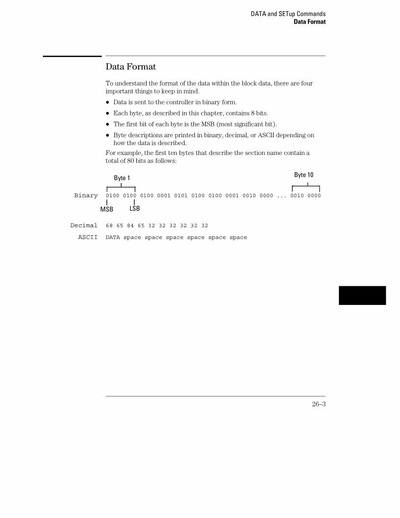
Data Format
To understand the format of the data within the block data, there are fourimportant things to keep in mind.
• Data is sent to the controller in binary form.
• Each byte, as described in this chapter, contains 8 bits.
• The first bit of each byte is the MSB (most significant bit).
• Byte descriptions are printed in binary, decimal, or ASCII depending onhow the data is described.
For example, the first ten bytes that describe the section name contain atotal of 80 bits as follows:
Binary 0100 0100 0100 0001 0101 0100 0100 0001 0010 0000 ... 0010 0000
Decimal 68 65 84 65 32 32 32 32 32 32
ASCII DATA space space space space space space
Byte 1 Byte 10
MSB LSB
DATA and SETup CommandsData Format
26–3

:SYSTem:DATA
Command :SYSTem:DATA <block_data>
The SYSTem:DATA command transmits the acquisition memory data fromthe controller to the 1660-series logic analyzer.
The block data consists of a variable number of bytes containing informationcaptured by the acquisition chips. The information will be in one of threeformats, depending on the type of data captured. The three formats areglitch, transitional, conventional timing or state. Each format is described inthe "Acquisition Data Description" section later in this chapter. Since noparameter checking is performed, out-of-range values could cause instrumentlockup; therefore, care should be taken when transferring the data string intothe logic analyzer.
The <block_data> parameter can be broken down into a<block_length_specifier> and a variable number of <section>’s.
The <block_length_specifier> always takes the form #8DDDDDDDD. Each Drepresents a digit (ASCII characters "0" through "9"). The value of the eightdigits represents the total length of the block (all sections). For example, ifthe total length of the block is 14522 bytes, the block length specifier wouldbe "#800014522".
Each <section> consists of a <section header> and <section data>. The<section data> format varies for each section. For the DATA instruction,there is only one <section>, which is composed of a data preamble followedby the acquisition data. This section has a variable number of bytesdepending on configuration and amount of acquired data.
<block_data> <block_length_specifier><section>
<block_length_ specifier>
#8<length>
<length> The total length of all sections in byte format (must be represented with 8digits)
<section> <section header><section data>
DATA and SETup Commands:SYSTem:DATA
26–4

<section_header>
16 bytes, described in chapter 26, "Section Header Description".
<section_data> Format depends on the specific section.
Example OUTPUT XXX;":SYSTEM:DATA" <block_data>
The total length of a section is 16 (for the section header) plus the length of thesection data. So when calculating the value for <length>, don’t forget toinclude the length of the section headers.
Query :SYSTem:DATA?
The SYSTem:DATA query returns the block data to the controller. The datasent by the SYSTem:DATA query reflect the configuration of the machineswhen the last run was performed. Any changes made since then througheither front-panel operations or programming commands do not affect thestored configuration.
Returned Format [:SYSTem:DATA] <block_data><NL>
Example See "Transferring the logic analyzer acquired data" in chapter 36,"Programming Examples" for an example.
DATA and SETup Commands:SYSTem:DATA
26–5

Section Header Description
The section header uses bytes 1 through 16 (this manual begins counting at1; there is no byte 0). The 16 bytes of the section header are as follows:
Byte Position
1 10 bytes - Section name ("DATA space space space space space space" inASCII for the DATA instruction).
11 1 byte - Reserved
12 1 byte - Module ID (0010 0000 binary or 32 decimal for the 1660-series logicanalyzers)
13 4 bytes - Length of section in number of bytes that, when converted todecimal, specifies the number of bytes contained in the section.
Section Data
For the SYSTem:DATA command, the <section data> parameter consists oftwo parts: the data preamble and the acquisition data. These are describedin the following two sections.
Data Preamble Description
The block data is organized as 160 bytes of preamble information, followed bya variable number of bytes of data. The preamble gives information for eachanalyzer describing the amount and type of data captured, where the tracepoint occurred in the data, which pods are assigned to which analyzer, andother information. The values stored in the preamble represent the captureddata currently stored in this structure and not the current analyzerconfiguration. For example, the mode of the data (bytes 21 and 49) may beSTATE with tagging, while the current setup of the analyzer is TIMING.
The preamble (bytes 17 through 176) consists of the following 160 bytes:
17 2 bytes - Instrument ID (always 1660 decimal for 1660-series logic analyzers)
19 1 byte - Revision Code
20 1 byte - number of acquisition chips used in last acquisition
DATA and SETup CommandsSection Header Description
26–6
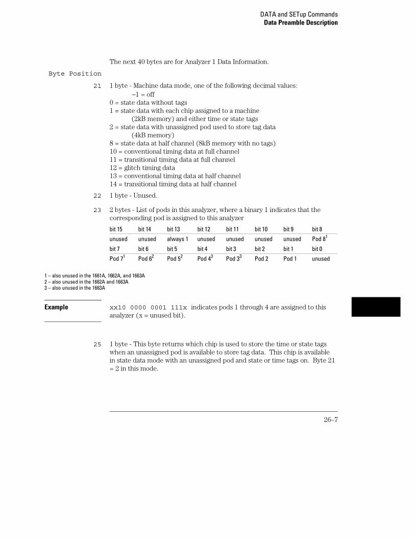
The next 40 bytes are for Analyzer 1 Data Information.
Byte Position
21 1 byte - Machine data mode, one of the following decimal values: −1 = off0 = state data without tags1 = state data with each chip assigned to a machine (2kB memory) and either time or state tags2 = state data with unassigned pod used to store tag data (4kB memory)8 = state data at half channel (8kB memory with no tags)10 = conventional timing data at full channel11 = transitional timing data at full channel12 = glitch timing data13 = conventional timing data at half channel14 = transitional timing data at half channel
22 1 byte - Unused.
23 2 bytes - List of pods in this analyzer, where a binary 1 indicates that thecorresponding pod is assigned to this analyzer
bit 15 bit 14 bit 13 bit 12 bit 11 bit 10 bit 9 bit 8
unused unused always 1 unused unused unused unused Pod 81
bit 7 bit 6 bit 5 bit 4 bit 3 bit 2 bit 1 bit 0
Pod 71 Pod 62 Pod 52 Pod 43 Pod 33 Pod 2 Pod 1 unused
1 – also unused in the 1661A, 1662A, and 1663A2 – also unused in the 1662A and 1663A3 – also unused in the 1663A
Example xx10 0000 0001 111x indicates pods 1 through 4 are assigned to thisanalyzer (x = unused bit).
25 1 byte - This byte returns which chip is used to store the time or state tagswhen an unassigned pod is available to store tag data. This chip is availablein state data mode with an unassigned pod and state or time tags on. Byte 21= 2 in this mode.
DATA and SETup CommandsData Preamble Description
26–7

Byte Position
26 1 byte - Master chip for this analyzer. This decimal value returns whichchip’s time tag data is valid in a non-transitional mode; for example, statewith time tags.
5 - pods 1 and 2 2 - pods 7 and 83
4 - pods 3 and 41 1 - unused
3 - pods 5 and 62 0 - unused
– 1 - no chip
1 – also unused in the 1663A2 – also unused in the 1662A and 1663A3 – also unused in the 1661A, 1662A, and 1663A
27 6 bytes - Unused
33 8 bytes - A decimal integer representing sample period in picoseconds(timing only).
Example The following 64 bits in binary would equal 8,000 picoseconds or, 8nanoseconds:
00000000 00000000 00000000 00000000 00000000 00000000 00011111 01000000
41 8 bytes - Unused
49 1 byte - Tag type for state only in one of the following decimal values:0 = off1 = time tags2 = state tags
50 1 byte - Unused
51 8 bytes - A decimal integer representing the time offset in picoseconds fromwhen this analyzer is triggered and when this analyzer provides an outputtrigger to the IMB or port out. The value for one analyzer is always zero andthe value for the other analyzer is the time between the triggers of the twoanalyzers.
59 2 bytes - Unused
DATA and SETup CommandsData Preamble Description
26–8

Byte Position
61 40 bytes - The next 40 bytes are for Analyzer 2 Data Information. They areorganized in the same manner as Analyzer 1 above, but they occupy bytes 61through 100.
101 26 bytes - Number of valid rows of data (starting at byte 177) for each pod.The 26 bytes of this group are organized as follows:Bytes 1 and 2 - UnusedBytes 3 and 4 - Unused.Bytes 5 and 6 - Unused.Bytes 7 and 8 - Unused.Bytes 9 and 10 - Unused.Bytes 11 and 12 contain the number of valid rows of data for pod 8 of the1660A only. Unused in the other 1660-series logic analyzers.Bytes 13 and 14 contain the number of valid rows of data for pod 7 of the1660A only. Unused in the other 1660-series logic analyzersBytes 15 and 16 contain the number of valid rows of data for pod 6 of the1660A and 1661A only.Bytes 17 and 18 contain the number of valid rows of data for pod 5 of the1660A and 1661A only.Bytes 19 and 20 contain the number of valid rows of data for pod 4 of the1660A, 1661A, and 1662A only.Bytes 21 and 22 contain the number of valid rows of data for pod 3 of the1660A, 1661A, and 1662A only.Bytes 23 and 24 contain the number of valid rows of data for pod 2 of allmodels of the 1660-series logic analyzers.Bytes 25 and 26 contain the number of valid rows of data for pod 1 of allmodels of the 1660-series logic analyzers.
DATA and SETup CommandsData Preamble Description
26–9
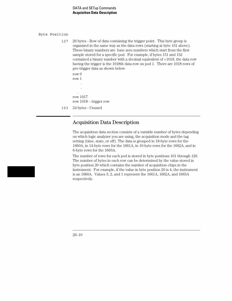
Byte Position
127 26 bytes - Row of data containing the trigger point. This byte group isorganized in the same way as the data rows (starting at byte 101 above).These binary numbers are base zero numbers which start from the firstsample stored for a specific pod. For example, if bytes 151 and 152contained a binary number with a decimal equivalent of +1018, the data rowhaving the trigger is the 1018th data row on pod 1. There are 1018 rows ofpre-trigger data as shown below.
row 0row 1 . .
.row 1017row 1018 – trigger row
153 24 bytes - Unused
Acquisition Data Description
The acquisition data section consists of a variable number of bytes dependingon which logic analyzer you are using, the acquisition mode and the tagsetting (time, state, or off). The data is grouped in 18-byte rows for the1660A, in 14-byte rows for the 1661A, in 10-byte rows for the 1662A, and in6-byte rows for the 1663A.
The number of rows for each pod is stored in byte positions 101 through 126.The number of bytes in each row can be determined by the value stored inbyte position 20 which contains the number of acquisition chips in theinstrument. For example, if the value in byte position 20 is 4, the instrumentis an 1660A. Values 3, 2, and 1 represent the 1661A, 1662A, and 1663Arespectively.
DATA and SETup CommandsAcquisition Data Description
26–10

Byte Position
clocklines
Pod 81 Pod 71 pod 62 pod 52 pod 43 pod 33 pod 2 pod 14
177 2 bytes 2 bytes 2 bytes 2 bytes 2 bytes 2 bytes 2 bytes 2 bytes 2 bytes
195 2 bytes 2 bytes 2 bytes 2 bytes 2 bytes 2 bytes 2 bytes 2 bytes 2 bytes
. . . . . . . . . .
. . . . . . . . . .
. . . . . . . . . .
(x) 2 bytes 2 bytes 2 bytes 2 bytes 2 bytes 2 bytes 2 bytes 2 bytes 2 bytes
1 – unused in the 1661A, 1662A, and 1663A2 – also unused in the 1662A and 1663 A3 – also unused in the 1663A4 – The headings are not a part of the returned data.
Row (x) is the highest number of valid rows specified by the bytes in bytepositions 101 through 126 in all modes and when neither analyzer is in glitchmode. In the glitch mode, row (x) is the larger of:
1. The highest number of valid rows specified by the bytes in bytepositions 101 through 126; or,
2. 2048 + the highest number of valid rows for the pods assigned tothe timing analyzer, when one or more glitches are detected.
The clock-line bytes for the 1660A, which also includes 2 additional data lines(D), are organized as follows: xxxx xxPN xxDD MLKJ
The clock-line bytes for the 1661A and 1662A are organized as follows: xxxx xxxx xxxx MLKJ
The clock-line bytes for the 1663A are organized as follows: xxxx xxxx xxxx xxKJ
DATA and SETup CommandsAcquisition Data Description
26–11

Time Tag Data Description
The time tag data starts at the end of the acquired data. Each data row hasan 8-byte time tag for each chip (2-pod set). The starting location of thetime tag data is immediately after the last row of valid data (maximum databyte + 1). If an analyzer is in a non-transitional mode, the master chip (byte26) is the only chip with valid time-tag data. The time tag data is a decimalinteger representing time in picoseconds for both timing and state time tags.For state tags in the state analyzer, tag data is a decimal integer representingthe number of states.
Time Tag Block (for the 1660A)
Byte 1 through 8 (64 bits starting with the MSB) - First sample tag for pods 1and 2.
Byte 9 through 16 (64 bits starting with the MSB) - Second sample tag forpods 1 and 2.
.
.
.
Byte (w) through (w + 7) (64 bits starting with the MSB) - Last sample tagfor pods 1 and 2.
Byte (w + 8 ) through (w + 15) (64 bits starting with the MSB) - First sampletag for pods 3 and 4.
Byte (w + 16 ) through (w + 23) (64 bits starting with the MSB) - Secondsample tag for pods 3 and 4.
.
.
.
Byte (x) through (x+ 7) (64 bits starting with the MSB) - Last sample tag forpods 3 and 4.
DATA and SETup CommandsTime Tag Data Description
26–12

Byte (x + 8 ) through (x + 15) (64 bits starting with the MSB) - First sampletag for pods 5 and 6.
Byte (x + 16 ) through (x + 23) (64 bits starting with the MSB) - Secondsample tag for pods 5 and 6.
.
.
.
Byte (y) through (y+ 7) (64 bits starting with the MSB) - Last sample tag forpods 5 and 6.
Byte (y + 8 ) through (y + 15) (64 bits starting with the MSB) - First sampletag for pods 7 and 8.
Byte (y + 16 ) through (y + 23) (64 bits starting with the MSB) - Secondsample tag for pods 7 and 8.
.
.
.
Byte (z) through (z+ 7) (64 bits starting with the MSB) - Last sample tag forpods 7 and 8.
DATA and SETup CommandsTime Tag Data Description
26–13

Glitch Data Description
In the glitch mode, each pod has two bytes assigned to indicate whereglitches occur in the acquired data. For each row of acquired data there willbe a corresponding row of glitch data. The glitch data is organized in thesame way as the acquired data. The glitch data is grouped in 18-byte rowsfor the 1660A. The number of rows is stored in byte positions 101 through126. The starting byte of the glitch data is an absolute starting pointregardless of the number of rows of acquired data.
A binary 1 in the glitch data indicates a glitch was detected. For example, if aglitch occurred on bit 1 of pod 8 in data row 1 of an 1660A, bytes 37043 and37044 would contain:
0000 0000 0000 0010
Byte Position
clocklines
Pod 81 Pod 71 pod 62 pod 52 pod 43 pod 33 pod 2 pod 14
37041 2 bytes 2 bytes 2 bytes 2 bytes 2 bytes 2 bytes 2 bytes 2 bytes 2 bytes
37059 2 bytes 2 bytes 2 bytes 2 bytes 2 bytes 2 bytes 2 bytes 2 bytes 2 bytes
. . . . . . . . . .
. . . . . . . . . .
. . . . . . . . . .
(x) 2 bytes 2 bytes 2 bytes 2 bytes 2 bytes 2 bytes 2 bytes 2 bytes 2 bytes
1 – unused in the 1661A, 1662A, and 1663A2 – also unused in the 1662A and 1663 A3 – also unused in the 1663A4 – The headings are not a part of the returned data.
Byte 37043 Byte 37044
Bit 15 Bit 1
DATA and SETup CommandsGlitch Data Description
26–14
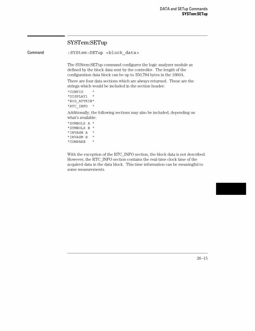
SYSTem:SETup
Command :SYStem:SETup <block_data>
The SYStem:SETup command configures the logic analyzer module asdefined by the block data sent by the controller. The length of theconfiguration data block can be up to 350,784 bytes in the 1660A.
There are four data sections which are always returned. These are thestrings which would be included in the section header:"CONFIG ""DISPLAY1 ""BIG_ATTRIB"
"RTC_INFO "
Additionally, the following sections may also be included, depending onwhat’s available:"SYMBOLS A ""SYMBOLS B ""INVASM A ""INVASM B ""COMPARE "
With the exception of the RTC_INFO section, the block data is not described.However, the RTC_INFO section contains the real-time clock time of theacquired data in the data block. This time information can be meaningful tosome measurements.
DATA and SETup CommandsSYSTem:SETup
26–15

<block_data> <block_length_specifier><section>
<block_length_ specifier>
#8<length>
<length> The total length of all sections in byte format (must be represented with 8digits)
<section> <section_header><section_data>[<section_data>...]
<section_header>
16 bytes in the following format:10 bytes for the section name 1 bytereserved 1 byte for the module ID code (32 for the 1660-series logic analyzer)4 bytes for the length of section data in number of bytes that, whenconverted to decimal, specifies the number of bytes contained in the section.
The RTC_INFO section is described in the "RTC_INFO Section Description."
<section_data> Format depends on the section.
The total length of a section is 16 (for the section header) plus the length of thesection data. So when calculating the value for <length>, don’t forget toinclude the length of the section headers.
Example OUTPUT XXX;"SETUP" <block_data>
Query :SYStem:SETup?
The SYStem:SETup query returns a block of data that contains the currentconfiguration to the controller.
Returned Format [:SYStem:SETup] <block_data><NL>
Example See "Transferring the logic analyzer configuration" in Chapter 36,"Programming Examples" for an example.
DATA and SETup CommandsSYSTem:SETup
26–16

RTC_INFO Section Description
The RTC_INFO section contains the real time of the acquired data. Becausethe time of the acquired data is important to certain measurements, thissection describes how to find the real-time clock data.
Because the number of sections in the SETup data block depends on thelogic analyzer configuration, the RTC_INFO section will not always be in thesame location within the block. Therefore, the section must be found byname. Once the section is found, you can find the time by using thedescription in the following section:
#8<block_length>...[<section_name><section_length><section_data>]...
<block_length> Total length of all sections
<section_name> 10 bytes - Section name. "RTC_INFO space space"
<section_length>
4 bytes - Length of section. 8 bytes, decimal, for RTC_INFO section.
<section_data> 10 bytes - Contains the real-time clock data described as follows:
Byte Position
1 1 byte - Year. A decimal integer that, when added to 1990, defines the year.For example, if this byte has a decimal value of 2, the year is 1992.
2 1 byte - Month. An integer from 1 to 12.
3 1 byte - Day. An integer from 1 to 31.
4 1 byte - Unused
5 1 byte - Hour. An integer from 1 to 23.
6 1 byte - Minute. An integer from 1 to 59.
7 1 byte - Second. An integer from 1 to 59.
8 1 byte - Unused.
DATA and SETup CommandsRTC_INFO Section Description
26–17

26–18

Part 4
Oscilloscope Commands


27
Oscilloscope Root LevelCommands

Introduction
Oscilloscope Root Level commands control the basic operation of theoscilloscope. Refer to figure 27-1 for the module level syntaxcommand diagram. The Root Level commands are:
• AUToscale
• DIGitize
27-2

Figure 27-1
Root Level Command Syntax Diagram
AUToscale
Command :AUToscale
The AUToscale command causes the oscilloscope to automatically select thevertical sensitivity, vertical offset, trigger source, trigger level and timebasesettings for optimum viewing of any input signals. The trigger source is thelowest channel on which the trigger was found. If no trigger is found, theoscilloscope defaults to auto-trigger. The display window configuration is notaltered by AUToscale.
Example: OUTPUT XXX;":AUTOSCALE"
To demonstrate a quick oscilloscope setup, we will use the AC CAL OUTPUTsignal available at the rear panel of the card. This square wave is normallyused for calibration and probe compensation.
Connect the AC CAL OUTPUT signal from the rear panel output connector toCHAN 1, also on the rear panel. Ensure that the mainframe is connected to acontroller. Enter the program listed on the next page and execute it.
Oscilloscope Root Level CommandsAUToscale
27-3

Example 10 OUTPUT XXX;":SELECT 2"20 OUTPUT XXX;":AUTOSCALE"25 WAIT 530 DIM Me$[200]40 OUTPUT ;":MEASURE:SOURCE CHANNEL1;ALL?"50 ENTER XXX;Me$60 PRINT Me$70 END
The three Xs (XXX) after the OUTPUT and ENTER statements in the aboveexample refer to the device address required for programming over either GPIBor RS-232-C. Refer to chapter 1, "Introduction to Programming" for informationon initializing the interface.
Program Comments
Line 10 selects the oscilloscope in slot B.
Line 20 causes the oscilloscope to execute the AUTOSCALE command.
Line 25 causes the oscilloscope to wait 5 seconds (the time you allowfor the measurement to be complete).
Line 30 dimensions and reserves memory for the string array.
Line 40 causes the oscilloscope to make all the parametricmeasurements of the Measure subsystem. The source for themeasurements is channel 1.
Line 50 enters data from the oscilloscope.
Line 60 causes the data to be printed either on controller screen orhardcopy, depending on the output device chosen.
For more information on the specific oscilloscope commands, refer tochapters 28 through 35 of this manual.
Oscilloscope Root Level CommandsAUToscale
27-4

DIGitize
Command :DIGitize
The DIGitize command is used to acquire waveform data for transfer overGPIB. The command initiates the Repetitive Run for the oscilloscope andany modules that are grouped together in Group Run through theIntermodule Bus. If a RUNtil condition has been specified in any module, theoscilloscope and the grouped modules will acquire data until the RUNtilconditions have been satisfied.
The Acquire subsystem commands may be used to set up conditions such asacquisition type and average count for the DIGitize command. See theAcquire subsystem for the description of these commands.
When a count number in the average acquisition type has been specified, theoscilloscope and all grouped modules will acquire data until these conditionshave been satisfied.
When both the RUNtil and the ACQuire:COUNt have been satisfied, theacquisition will stop.
For a faster data transfer rate over the interface bus, display a menu that hasno waveforms on screen.
The DIGitize command is an overlap command, thus ensure that all data hasbeen acquired and stored in the channel buffers before executing any othercommands. The MESE command and the MESR query may be used to checkfor run complete or a WAIt instruction may be inserted after the DIGitizecommand to ensure enough time for command execution.
Example OUTPUT XXX;":DIGITIZE"
An example using the DIGitize command can be found in Chapter 36,Programming Examples.
Oscilloscope Root Level CommandsDIGitize
27-5

27-6

28
ACQuire Subsystem

Introduction
The Acquire Subsystem commands are used to set up acquisitionconditions for the DIGitize command. The subsystem containscommands to select the type of acquisition and the number ofaverages to be taken if the average type is chosen. Refer to Figure28-1 for the ACQuire Subsystem Syntax Diagram. The ACQuireSubsystem commands are:
• COUNt
• TYPE
28-2

Figure 28-1
ACQuire Subsystem Syntax Diagram
Table 28-1 ACQuire Parameter Values
Parameter Value
count_arg An integer that specifies thenumber of averages to be taken ofeach time point. The choices are2, 4, 8, 16, 32, 64, 128, or 256.
Acquisition Type Normal
In the Normal mode, with the ACCumulate command OFF, the oscilloscopeacquires waveform data and then displays the waveform. When theoscilloscope makes a new acquisition, the previously acquired waveform iserased from the display and replaced by the newly acquired waveform. Whenthe ACCumulate command is ON, the oscilloscope displays all the waveformacquisitions without erasing the previously acquired waveform.
Acquisition Type Average
In the Average mode, the oscilloscope averages the data points on thewaveform with previously acquired data. Averaging helps eliminate randomnoise from the displayed waveform. In this mode the ACCumulate commandis OFF. When Average mode is selected, the number of averages must alsobe specified using the COUNt command. Previously averaged waveform datais erased from the display and the newly averaged waveform is displayed.
ACQuire Subsystem
28-3

COUNt
Command :ACQuire:COUNt <count>
The COUNt command specifies the number of acquisitions for the runningweighted average. This command generates an error if Normal acquisitionmode is specified.
<count> {2|4|8|16|32|64|128|256}
Example OUTPUT XXX;":ACQUIRE:COUNT 16"
Query :ACQuire:COUNt?
The COUNt query returns the last specified count. Returned Format [:ACQuire:COUNt] <count><NL>
Example OUTPUT XXX;":ACQ:COUN?"
TYPE
Command :ACQuire:TYPE {NORMal|AVERage}
The TYPE command selects the type of acquisition that is to take placewhen a DIGitize or STARt command is executed. One of two acquisitiontypes may be chosen: the NORMal or AVERage mode.
Example OUTPUT XXX;":ACQUIRE:TYPE NORMAL"
ACQuire Subsystem COUNt
28-4

Query :ACQuire:TYPE?
The TYPE query returns the last specified type. Returned Format [:ACQuire:TYPE] {NORMal|AVERage}<NL>
Example OUTPUT XXX;":ACQUIRE:TYPE?"
ACQuire Subsystem TYPE
28-5

28-6

29
CHANnel Subsystem

Introduction
The Channel Subsystem commands control the channel display andthe vertical axis of the oscilloscope. Each channel must beprogrammed independently for all offset, range and probe functions.When ECL or TTL commands are executed, the vertical range, offsetand trigger levels are automatically set for optimum viewing. Refer tofigure 29-1 for the CHANnel Subsystem Syntax Diagram. TheCHANnel Subsystem commands are:
• COUPling
• ECL
• OFFSet
• PROBe
• RANGe
• TTL
29-2

Figure29-1
CHANnel Subsystem Syntax Diagram
CHANnel Subsystem
29-3
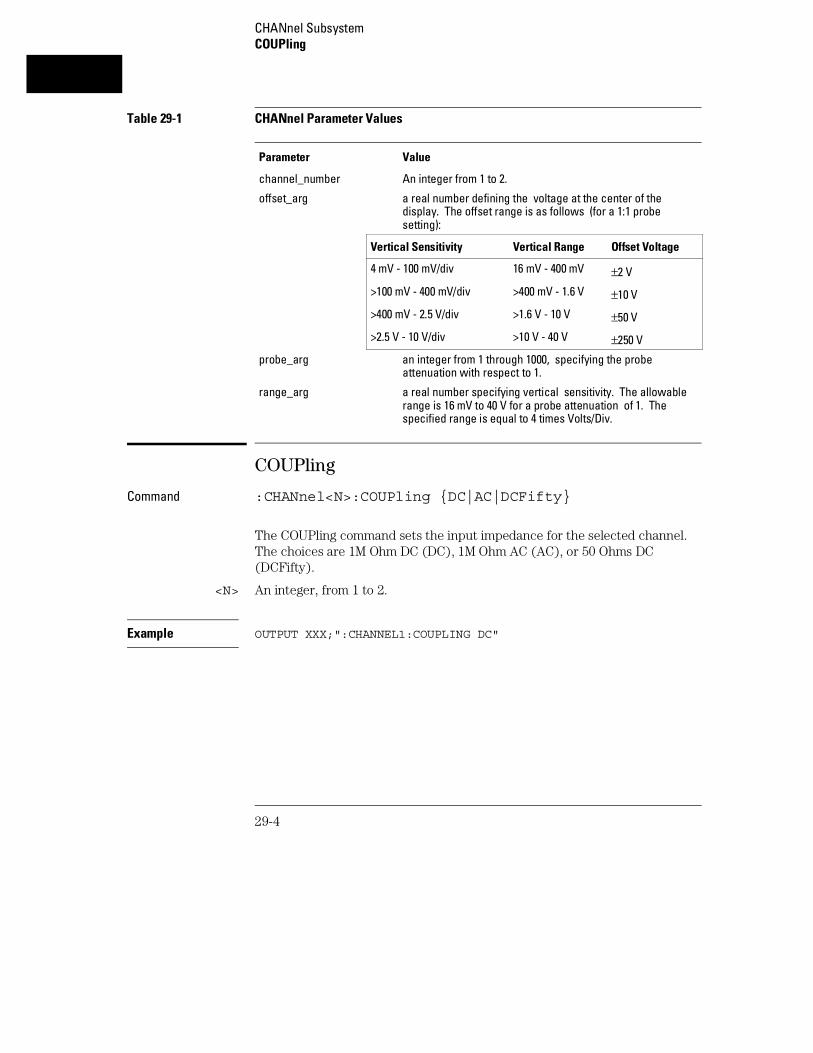
Table 29-1 CHANnel Parameter Values
Parameter Value
channel_number An integer from 1 to 2.
offset_arg a real number defining the voltage at the center of thedisplay. The offset range is as follows (for a 1:1 probesetting):
Vertical Sensitivity Vertical Range Offset Voltage
4 mV - 100 mV/div 16 mV - 400 mV ±2 V
>100 mV - 400 mV/div >400 mV - 1.6 V ±10 V
>400 mV - 2.5 V/div >1.6 V - 10 V ±50 V
>2.5 V - 10 V/div >10 V - 40 V ±250 V
probe_arg an integer from 1 through 1000, specifying the probeattenuation with respect to 1.
range_arg a real number specifying vertical sensitivity. The allowablerange is 16 mV to 40 V for a probe attenuation of 1. Thespecified range is equal to 4 times Volts/Div.
COUPling
Command :CHANnel<N>:COUPling {DC|AC|DCFifty}
The COUPling command sets the input impedance for the selected channel.The choices are 1M Ohm DC (DC), 1M Ohm AC (AC), or 50 Ohms DC(DCFifty).
<N> An integer, from 1 to 2.
Example OUTPUT XXX;":CHANNEL1:COUPLING DC"
CHANnel SubsystemCOUPling
29-4

Query :CHANnel<N>:COUPling?
The COUPling query returns the current input impedance for the specifiedchannel.
Returned Format [:CHANnel<N>:COUPling:] {DC|AC|DCFifty}<NL>
Example OUTPUT XXX;":CHANNEL1:COUPLING?"
ECL
Command :CHANnel<N>:ECL
The ECL command sets the vertical range, offset, and trigger levels for theselected input channel for optimum viewing of ECL signals. The set ECL:values are:
Range: 2.0 V (500 mV per division)
Offset: -1.3 V
Trigger level: -1.3 V
<N> An integer, from 1 to 2.
Example OUTPUT XXX;":CHANNEL1:ECL"
To return to "Preset User", change the CHANnel:RANGe, CHANnel:OFFSet, orTRIGger:LEVel value.
CHANnel SubsystemECL
29-5

OFFSet
Command :CHANnel<N>:OFFSet <value>
The OFFSet command sets the voltage that is represented at center screenfor the selected channel. The allowable offset voltage <value> is shown inthe table below. The table represents values for a Probe setting of 1:1. Theoffset value is recompensated whenever the probe attenuation factor ischanged.
<N> An integer, from 1 to 2..
<value> allowable offset voltage value shown in the table below.
Vertical Range Offset Voltage
16 mV - 400 mV ±2 V
>400 mV - 1.6 V ±10 V
>1.6 V - 10 V ±50 V
>10 V - 40 V ±250 V
Example OUTPUT XXX;":CHAN1:OFFS 1.5"
Query :CHANnel<N>:OFFSet?
The OFFSet query returns the current value for the selected channel.
<N> An integer, from 1 to 2.
Returned Format [:CHANnel<N>:OFFSet] <value><NL>
Example OUTPUT XXX;":CHANNEL1:OFFSET?"
CHANnel SubsystemOFFSet
29-6

PROBe
Command :CHANnel<N>:PROBe <atten>
The PROBe command specifies the attenuation factor for an external probeconnected to a channel. The command changes the channel voltagereferences such as range, offset, trigger level and automatic measurements.The actual sensitivity is not changed at the channel input. The allowableprobe attenuation factor is an integer from 1 to 1000.
<N> An integer, from 1 to 2.
<atten> An integer from 1 to 1000
Example OUTPUT XXX;":CHAN1:PROB 10"
Query :CHANnel<N>:PROBe?
The PROBe query returns the probe attenuation factor for the selectedchannel.
Returned Format [:CHANnel<N>:PROBe]<atten><NL>
Example OUTPUT XXX;":CHANNEL1:PROBE?"
CHANnel SubsystemPROBe
29-7

RANGe
Command :CHANnel<N>:RANGe <range>
The RANGe command defines the full-scale (4 * Volts/Div) vertical axis ofthe selected channel. The values for the RANGe command are dependenton the current probe attenuation factor for the selected channel. Theallowable range for a probe attenuation factor of 1:1 is 16 mV to 40 V. For alarger probe attenuation factor, multiply the range limit by the probeattenuation factor.
<N> An integer, from 1 to 2.
<range> 16 mV to 40 V for a probe attenuation factor of 1:1
Example OUTPUT XXX;":CHANNEL1:RANGE 4.8"
Query :CHANnel<N>:RANGe?
The RANGe query returns the current range setting. Returned Format [:CHANnel<N>:RANGe] <range><NL>
Example OUTPUT XXX;":CHANNEL1:RANGE?"
CHANnel SubsystemRANGe
29-8

TTL
Command :CHANnel<N>:TTL
The TTL command sets the vertical range, offset, and trigger level for theselected input channel for optimum viewing of TTL signals. The set TTLvalues are:
Range: 6.0 V (1.50 V per division)
Offset: 2.5 V
Trigger Level: 1.62 V
<N> An integer, from 1 to 2.
Example OUTPUT XXX;":CHANNEL1:TTL"
To return to "Preset User" change the CHANnel:RANGe, CHANel:OFFSet, orTRIGger:LEVel value.
CHANnel SubsystemTTL
29-9

29-10
30
DISPlay Subsystem

Introduction
The Display Subsystem is used to control the display of data. Refer toFigure 30-1 for the DISPlay Subsystem Syntax Diagram. The DISPlaySubsystem commands are:
• ACCumulate
• CONNect
• INSert
• LABel
• MINus
• OVERlay
• PLUS
• REMove
30-2

Figure 30-1
DISPlay Subsystem Syntax Diagram
DISPlay Subsystem
30-3
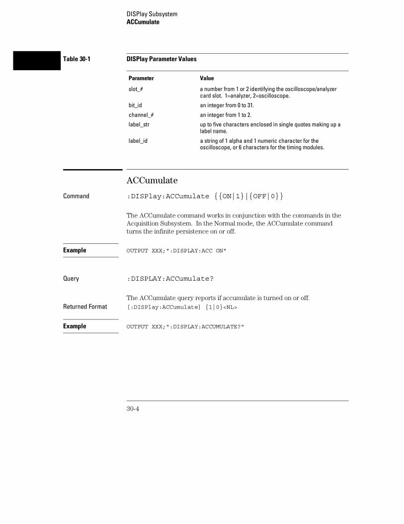
Table 30-1 DISPlay Parameter Values
Parameter Value
slot_# a number from 1 or 2 identifying the oscilloscope/analyzercard slot. 1=analyzer, 2=oscilloscope.
bit_id an integer from 0 to 31.
channel_# an integer from 1 to 2.
label_str up to five characters enclosed in single quotes making up alabel name.
label_id a string of 1 alpha and 1 numeric character for theoscilloscope, or 6 characters for the timing modules.
ACCumulate
Command :DISPlay:ACCumulate {{ON|1}|{OFF|0}}
The ACCumulate command works in conjunction with the commands in theAcquisition Subsystem. In the Normal mode, the ACCumulate commandturns the infinite persistence on or off.
Example OUTPUT XXX;":DISPLAY:ACC ON"
Query :DISPLAY:ACCumulate?
The ACCumulate query reports if accumulate is turned on or off.Returned Format [:DISPlay:ACCumulate] {1|0}<NL>
Example OUTPUT XXX;":DISPLAY:ACCUMULATE?"
DISPlay SubsystemACCumulate
30-4

CONNect
Command :DISPlay:CONNect {{ON|1}|{OFF|0}}
The CONNect command sets the Connect Dots mode. When ON, eachdisplayed sample dot will be connected to the adjacent dot by a straight line.The waveform is easier to see in this mode. When OFF, only the samplingpoints will be displayed.
Example OUTPUT XXX;":DISPLAY:CONNECT ON"
Query :DISPlay:CONNect?
The CONNect query reports if connect is on or off.Returned Format [:DISPlay:CONNect] {1|0}<NL>
Example OUTPUT XXX;":DISPLAY:CONNECT?"
INSert
The INSert command inserts waveforms into the current display.Time-correlated waveforms from the logic analyzer may also be added to thecurrent display. The waveforms are added just below any currently displayedsignals. Only two oscilloscope waveforms can be displayed at any time.
The first parameter is optional and specifies the module from where thewaveform is to be taken. The module number is the same as the slot numberin which the master card is installed. If a module is not specified, the currentmodule is assumed. The second parameter is the label of the waveform thatis to be added to the current display. The label names depend on the slot inwhich the acquisition cards are installed.
To insert a waveform from the oscilloscope to the oscilloscope display:Command :DISPlay:INSert [<module number>,]<label>
DISPlay SubsystemCONNect
30-5
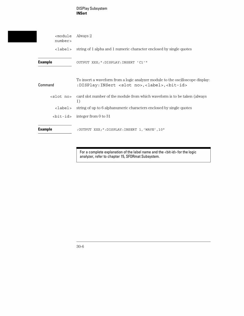
<modulenumber>
Always 2
<label> string of 1 alpha and 1 numeric character enclosed by single quotes
Example OUTPUT XXX;":DISPLAY:INSERT ’C1’"
To insert a waveform from a logic analyzer module to the oscilloscope display:Command :DISPlay:INSert <slot no>,<label>,<bit-id>
<slot no> card slot number of the module from which waveform is to be taken (always1)
<label> string of up to 6 alphanumeric characters enclosed by single quotes
<bit-id> integer from 0 to 31
Example :OUTPUT XXX;":DISPLAY:INSERT 1,’WAVE’,10"
For a complete explanation of the label name and the <bit-id> for the logicanalyzer, refer to chapter 15, SFORmat Subsystem.
DISPlay SubsystemINSert
30-6

LABel
Command :DISPlay:LABel CHANnel<N>,<label_string>
The LABel command is used to assign a label string to an oscilloscopechannel. For single channel traces, the label string (up to five characters)appears on the left of the waveform area of the display. Note that the labelstring cannot be used in place of the channel number when programming theoscilloscope module.
<N> an integer from 1 to 2
<label_str> a string of up to five characters enclosed in single quotes
Example OUTPUT XXX;":DISPLAY:LABEL CHANNEL1,’CLK’"
Query :DISPlay:LABel? CHANnel<N>
The LABel query returns the label string assigned to the specified channel. Ifno label has been assigned, the default channel identifier (single characterand single number) is returned.
Returned Format [:DISPlay:LABel] CHANnel<N>,<label_str><NL>
Example OUTPUT XXX;":DISPLAY:LABEL? CHANNEL2"
DISPlay SubsystemLABel
30-7

MINus
Command :DISPlay:MINus [<module_number>,]<label>,<label>
The MINus command algebraically subtracts one channel from another andinserts the resultant waveform to the display. The first parameter is anoptional module specifier. The module is identified by the slot number thatcontains the oscilloscope card (always 2). The next two parameters are thelabel of the waveform selected to be added to the display. The label namesare defined in the same manner as the INSert command.
<module_number>
Always 2
<label> string of 1 alpha and 1 numeric character enclosed by single quotes
Example OUTPUT XXX;":DISPLAY:MINUS 2,’C1’,’C2’"
OVERlay
Command :DISPlay:OVERlay <label>,<label>
The OVERlay command overlays oscilloscope waveforms. The syntaxparameters are the labels of the waveforms that are to be overlaid. Onlywaveforms sharing a common card can be overlaid. A label may be used onlyonce with each OVERlay command.
<label> string of 1 alpha and 1 numeric character enclosed by single quotes
Example OUTPUT XXX;":DISPLAY:OVERLAY ’C1’,’C2’"
DISPlay SubsystemMINus
30-8

PLUS
Command :DISPlay:PLUS [<module_number>,]<label>,<label>
The PLUS command algebraically adds two channels and inserts theresultant waveform to the current display. The first parameter is an optionalmodule specifier and needs to be used only if another module is displayed.The next parameters are the labels of the waveform that are to be added.
<module_number>
Always 2
<label> string of 1 alpha and 1 numeric character enclosed by single quotes
Example OUTPUT XXX;":DISPLAY:PLUS 2,’C1’,’C2’"
REMove
Command :DISPlay:REMove
The REMove command removes all displayed waveforms from the currentdisplay.
Example OUTPUT XXX;":DISPLAY:REMOVE"
DISPlay SubsystemPLUS
30-9

DISPlay SubsystemREMove
30-10

31
MARKer Subsystem

Introduction
In addition to automatic parametric measurements, the oscilloscopehas four markers for making time and voltage measurement. Thesemeasurements may be made automatically or manually. Additionalfeatures include the centering of trigger or markers in the display area(CENTer) and the run until time (RUNTil) mode. The RUNTil modeallows you to set a stop condition based on the time interval betweenthe X marker and the O marker. When this condition is met, theoscilloscope will stop acquiring data. Refer to Figure 31-1 for theMarker Subsystem Syntax Diagram. The MARKer Subsystemcommands are:
• AVOLt • TMAXimum
• ABVolt • TMINimum
• BVOLt • TMODe
• CENTer • VMODe
• MSTats • VOTime
• OAUTo • VXTime
• OTIMe • VRUNs
• RUNTil • XAUTo
• SHOW • XTIMe
• TAVerage
• XOTime
31-2

Figure 31-1
MARKer Subsystem Syntax Diagram
MARKer Subsystem
31-3

Figure 31-1
MARKer Subsystem Syntax Diagram (Cont’d)
MARKer Subsystem
31-4

Figure 31-1
MARKer Subsystem Syntax Diagram (Cont’d)
Table 31-1 MARKer Parameter Values
Parameter Value
channel_# An integer from 1 to 2.
marker_time time in seconds from trigger marker to X or O marker
lt_arg time in seconds that specifies the less than (lt) RUNTil time
gt_arg time in seconds that specifies the greater than (gt) RUNTil time
inrange_gt time in seconds specifying the lower limit of the INRange runtime
inrange_lt time in seconds specifying the upper limit of the INRange runtime
level level in volts that specifies marker position
outrange_gt time in seconds specifying the lower limit of the OUTRange runtime
outrange_lt time in seconds specifying the upper limit of the OUTRange runtime
V level percentage of waveform voltage level, ranging from 10 to 90 of theVtop to Vbase voltage, or a specific voltage level
type ABSolute or PERCent
slope positive or negative slope
occurrence integer from 1 to 100
MARKer Subsystem
31-5
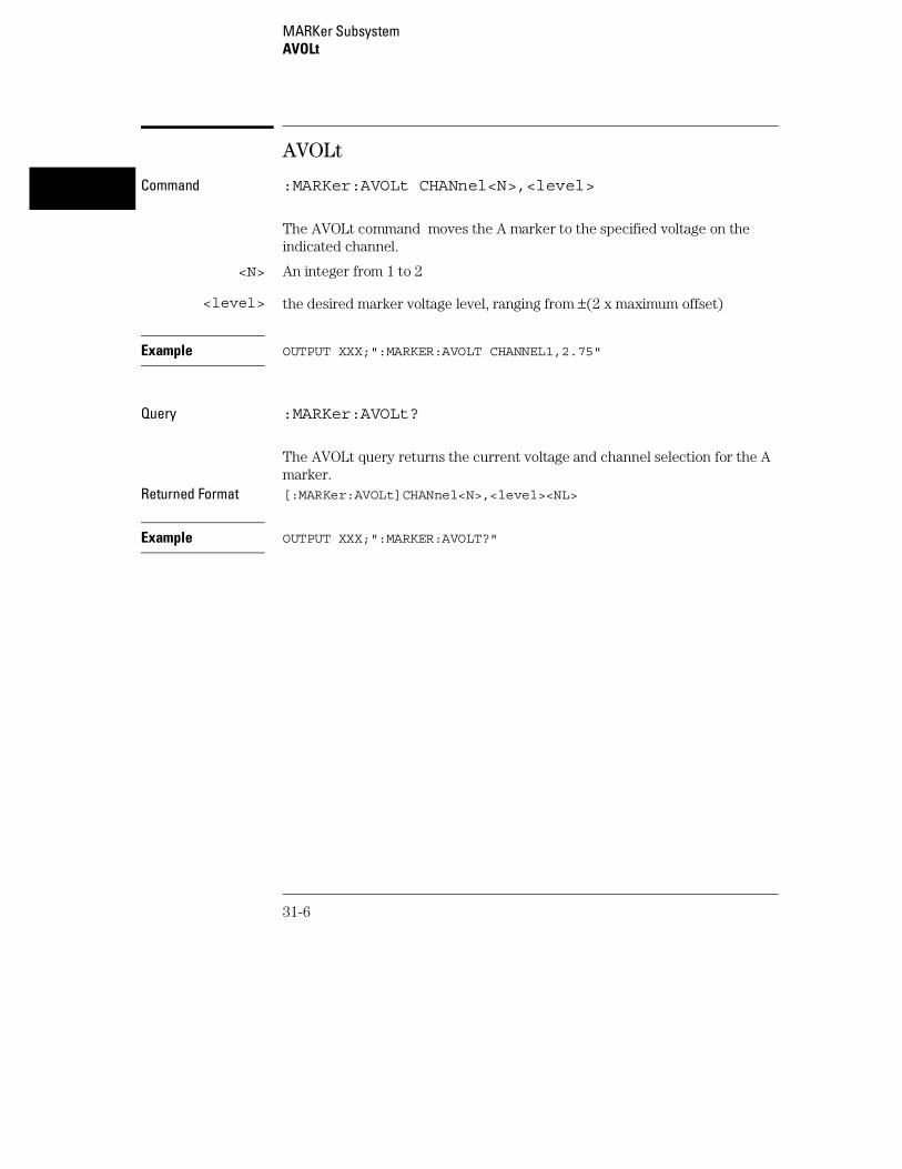
AVOLt
Command :MARKer:AVOLt CHANnel<N>,<level>
The AVOLt command moves the A marker to the specified voltage on theindicated channel.
<N> An integer from 1 to 2
<level> the desired marker voltage level, ranging from ±(2 x maximum offset)
Example OUTPUT XXX;":MARKER:AVOLT CHANNEL1,2.75"
Query :MARKer:AVOLt?
The AVOLt query returns the current voltage and channel selection for the Amarker.
Returned Format [:MARKer:AVOLt]CHANnel<N>,<level><NL>
Example OUTPUT XXX;":MARKER:AVOLT?"
MARKer SubsystemAVOLt
31-6

ABVolt?
Query :MARKer:ABVolt?
The ABVolt query returns the difference between the A marker voltage andthe B marker voltage (Vb - Va).
Returned Format [:MARKer:ABVolt]<level><NL>
<level> level in volts of the B marker minus the A marker
Example OUTPUT XXX;":MARKER:ABVOLT?"
BVOLt
Command :MARKer:BVOLt CHANnel<N>,<level>
The BVOLt command moves the B marker to the specified voltage on theindicated channel.
<N> An integer from 1 to 2
<level> the desired marker voltage level, ranging from ±(2 x maximum offset)
Example OUTPUT XXX;":MARKER:BVOLT CHANNEL1,2.75"
MARKer SubsystemABVolt?
31-7

Query :MARKer:BVOLt?
The BVOLt query returns the current voltage and channel selection for the Bmarker.
Returned Format [:MARKer:BVOLt]CHANnel<N>,<level><NL>
Example OUTPUT XXX;":MARKER:BVOLT?"
CENTer
Command :MARKer:CENTer {TRIGger|X|O}
The CENTer command allows you to position the indicated marker(TRIGger, X, or O) at the center of the waveform area on the scope display.The CENTer command adjusts the timebase delay to cause the trace to becentered around the indicated marker (S/DIV remains unchanged).
Example OUTPUT XXX;":MARKER:CENTER X"
MSTats
Command :MARKer:MSTats {{ON|1}|{OFF|0}}
The MSTats command allows you to turn statistics ON or OFF in the automarker mode. When statistics is turned on, Min X-O, Max X-O, and MeanX-O times are displayed on screen. When off, X-O, Trig-X, and Trig-O timeswill be displayed on screen.
Example OUTPUT XXX;":MARKER:MSTATS ON"
MARKer SubsystemCENTer
31-8

Query :MARKer:MSTats?
The MSTats query returns the current setting.Returned Format [:MARKer:MSTats]{1|0}<NL>
Example OUTPUT XXX;":MARKER:MSTATS?"
OAUTo
Command :MARKer:OAUTo{ MANual|CHANnel<N>,<type>,<level>,<slope>,<occurrence>}
The OAUTo command specifies the automatic placement specification forthe O marker. The first parameter specifies if automarker placement is to bein the manual mode or on a specified channel. If a channel is specified, fourother parameters must be included in the command syntax. The fourparameters are: marker type, level, the slope, and the occurrence count.
<N> An integer from 1 to 2
<type> ABSolute or PERCent
<level> percentage of waveform voltage level, ranging from 10 to 90 of the Vtop toVbase voltage or a voltage level
<slope> POSitive or NEGative
<occurrence> integer from 1 to 100
Example OUTPUT XXX;":MARKER:OAUTO CHANNEL1,PERCent,50,POSITIVE,5"
MARKer SubsystemOAUTo
31-9

Query :MARKer:OAUTo?
The OAUTo query returns the current settings.Returned Format [:MARKer:OAUTo] CHANnel<N>,<type>
<level>,<slope>,<occurrence><NL>
Example OUTPUT XXX;":MARKER:OAUTO?"
If <type> is not specified, the marker type will default to PERCent.
OTIMe
Command :MARKer:OTIMe <O marker time>
The OTIMe command moves the O marker to the specified time with respectto the trigger marker.
<O markertime>
time in seconds from trigger marker to O marker
Example OUTPUT XXX;":MARKER:OTIME 1E-6"
Query :MARKer:OTIMe?
The OTIMe query returns the time in seconds between the O marker and thetrigger marker.
Returned Format [:MARKer:OTIMe]<O marker time><NL>
Example OUTPUT XXX;":MARKER:OTIME?"
MARKer SubsystemOTIMe
31-10

RUNTil
Command :MARKer:RUNTil{OFF|LT,<time>|GT,<time>|INRange,<time>,<time>|OUTRange,<time>, <time>}
The RUNTil command allows you to set a stop condition based on the timeinterval between the X marker and the O marker. In repetitive runs, whenthe time specification is met, the oscilloscope stops acquiring data and theadvisory "Stop condition satisfied" will be displayed on screen.
<time> a real number specifying the time in seconds between the X and O markers
Example OUTPUT XXX;":MARKER:RUNTIL LT,1MS"
Query :MARKer:RUNTil?
The RUNTil query will return the current Run Until Time X - O (RUNTil)setting.
Returned Format [:MARKer:RUNTil] {OFF|LT,<time>|GT,<time>|INRange,<time>,<time>|OUTRange,<time>,<time>}<NL>
Example OUTPUT XXX;":MARKER:RUNTIL?"
MARKer SubsystemRUNTil
31-11

SHOW
Command :MARKer:SHOW {SAMPle|MARKer}
The SHOW command allows you to select either SAMPle rate or MARKerdata (when markers are enabled) to appear on the oscilloscope menus abovethe waveform area.
The SAMPle rate or MARKer data appears on the channel, trigger, display,and auto-measure menus. Marker data is always present on the markermenu. While sample rate data is only present on the marker menu when timemarkers are turned off.
Example OUTPUT XXX;":MARKER:SHOW MARKER"
TAVerage?
Query :MARKer:TAVerage?
The TAVerage query returns the average time between the X and O markers.If there is no valid data, the query returns 9.9E37.
Returned Format [:MARKER:TAVERAGE] <time value><NL>
<time value> real number
Example OUTPUT XXX;":MARKER:TAVERAGE?"
MARKer SubsystemSHOW
31-12

TMAXimum?
Query :MARKer:TMAXimum?
The TMAXimum query returns the value of the maximum time between theX and O markers. If there is no valid data, the query returns 9.9E37.
Returned Format [:MARKer:TMAXimum] <time value><NL>
<time value> real number
Example OUTPUT XXX;":MARKER:TMAXIMUM?"
TMINimum?
Query :MARKer:TMINimum?
The TMINimum query returns the value of the minimum time between the Xand O markers. If there is no valid data, the query returns 9.9E37.
Returned Format [:MARKer:TMINimum] <time value><NL>
<time value> real number
Example OUTPUT XXX;":MARKER:TMINIMUM?"
MARKer SubsystemTMAXimum?
31-13
TMODe
Command :MARKer:TMODe {OFF|ON|AUTO}
The TMODe command allows you to select the time marker mode. Thechoices are: OFF, ON and AUTO. When OFF, time marker measurementscannot be made. When the time markers are turned on, the X and O markerscan be moved to make time and voltage measurements. The AUTO modeallows you to make automatic marker placements by specifying channel,slope, and occurrence count for each marker. Also the Statistics mode maybe used when AUTO is chosen. Statistics mode allows you to makeminimum, maximum and mean time interval measurements from the Xmarker to the O marker.
Example OUTPUT XXX;":MARKER:TMODE ON"
Query :MARKer:TMODe?
The TMODe query returns the current marker mode choice.Returned Format [:MARKer:TMODe] <state><NL>
<state> ON or OFF or AUTO
Example OUTPUT XXX;":MARKER:TMODE?"
For compatibility with older modules, the MMODe command/query will functionthe same as the TMODe command/query.
MARKer SubsystemTMODe
31-14

VMODe
Command :MARKer:VMODe {{OFF|0} | {ON|1}}
The VMODe command allows you to select the voltage marker mode. Thechoices are: OFF or ON. When OFF, voltage marker measurements cannotbe made. When the voltage markers are turned on, the A and B markers canbe moved to make voltage measurements. When used in conjunction withthe time markers (TMODe), both "delta t" and "delta v" measurements arepossible.
Example OUTPUT XXX;":MARKER:VMODE OFF"
Query :MARKer:VMODe?
The VMODe query returns the current voltage marker mode choice.Returned Format [:MARKer:VMODe] <state><NL>
<state> 1 or 0
Example OUTPUT XXX;":MARKER:VMODE?"
MARKer SubsystemVMODe
31-15

VOTime?
Query :MARKer:VOTime? CHANNEL<N>
The VOTime query returns the current voltage level of the selected source atthe O marker.
Returned Format [:MARKer:VOTime]<level><NL>
<N> An integer from 1 to 2
<level> level in volts where the O marker crosses the waveform
Example OUTPUT XXX;":MARKER:VOTIME? CHANNEL1"
For compatibility with older modules, the OVOLt query will function the same asthe VOTime query.
VRUNs?
Query :MARKer:VRUNs?
The VRUNs query returns the number of valid runs and the total number ofruns made. Valid runs are those where the edge search for both the X and Omarkers was successful, resulting in valid marker time measurement.
Returned Format [:MARKer:VRUNs] <valid runs>,<total runs><NL>
<valid runs> positive integer
<total runs> positive integer
Example OUTPUT XXX;":MARKER:VRUNS?"
MARKer SubsystemVOTime?
31-16

VXTime?
Query :MARKer:XVOLt? CHANnel<N>
The VXTime query returns the current voltage level of the selected channelat the X marker.
Returned Format [:MARKer:VXTime]<level><NL>
<N> An integer from 1 to 2
<level> level in volts where the X marker crosses the waveform
Example OUTPUT XXX;":MARKER:VXTIME? CHANNEL1"
For compatibility with older modules, the XVOLt query will function the same asthe VXTime query.
MARKer SubsystemVXTime?
31-17

XAUTo
Command :MARKer:XAUTo{MANual|CHANnel<N>,<type>,<level>,<slope>,<occurrence>}
The XAUTo command specifies the automatic placement specification forthe X marker. The first parameter specifies if automarker placement is to bein the Manual mode or on a specified channel. If a channel is specified, fourother parameters must be included in the command syntax. The fourparameters are: marker type, level, slope and the occurrence count.
<N> An integer from 1 to 2
<type> ABSolute or PERCent
<level> percentage of waveform voltage level, ranging from 10 to 90 of the Vtop toVbase voltage or a voltage level
<slope> POSitive or NEGative
<occurrence> integer from 1 to 100
Example OUTPUT XXX;":MARKER:XAUTO CHANNEL1,ABS,4.75,POSITIVE,5"
Query :MARKer:XAUTo?
The XAUTo query returns the current settings. Returned Format [:MARKer:XAUTo] CHANnel
<N>,<type>,<level>,<slope>,<occurrence><NL>
Example OUTPUT XXX;":MARKER:XAUTO?"
If <type> is not specified, the marker type will default to PERCent.
MARKer SubsystemXAUTo
31-18

XOTime?
Query :MARKer:XOTime?
The XOTime query returns the time in seconds from the X marker to the Omarker. If data is not valid, the query returns 9.9E37.
Returned Format [:MARKer:XOTime]<time><NL>
<time> real number
Example OUTPUT XXX;":MARKER:XOTIME?"
XTIMe
Command :MARKer:XTIMe <X marker time>
The XTIMe command moves the X marker to the specified time with respectto the trigger marker.
<X markertime>
time in seconds from trigger marker to X marker
Example OUTPUT XXX;":MARKER:XTIME 1E-6"
MARKer SubsystemXOTime?
31-19

Query :MARKer:XTIMe?
The XTIMe query returns the time in seconds between the X marker and thetrigger marker.
Returned Format [:MARKer:XTIMe]<xmarker time><NL>
Example OUTPUT XXX;":MARKER:XTIME?"
MARKer SubsystemXTIMe
31-20
32
MEASure Subsystem
Introduction
The commands/queries in the Measure Subsystem are used to makeautomatic parametric measurements on displayed waveforms.Measurements are made on the displayed waveform(s) specified bythe SOURce command. If the source is not specified, the lastwaveform source specified is assumed. Measurements are made inthe following manner:
Frequency
The frequency of the first complete cycle displayed is measured using the50% level.
Period
The period of the first complete cycle displayed is measured at the 50% level.
Peak-to-Peak
The absolute minimum and the maximum voltages for the selected source aremeasured.
Positive Pulse Width
Pulse width is measured at the 50% level of the first displayed positive pulse.
Negative Pulse Width
Pulse width is measured at the 50% level of the first displayed negative pulse.
Risetime
The risetime of the first displayed rising edge is measured. To obtain thebest possible measurement accuracy, select the fastest sweep speed whilekeeping the rising edge on the display. The risetime is determined bymeasuring time at the 10% and the 90%voltage points of the rising edge.
Falltime
Falltime is measured between the 10% and 90% points of the first displayedfalling edge. To obtain the best possible measurement accuracy, select thefastest sweep speed possible while keeping the falling edge on the display.
32-2
Preshoot and Overshoot
Preshoot and overshoot measure the perturbation on a waveform above orbelow the top and base voltages.
Preshoot
Is a perturbation before a rising or a falling edge and measured as apercentage of the top-base voltage.
Overshoot
Is a perturbation after a rising or falling edge and is measured as a percentageof the top-base voltage.
For complete details of the measurement algorithms, refer to the User’sReference Manual.
Refer to Figure 32-1 for the MEASure Subsystem Syntax Diagram
Before using any of the Measure Subsystem queries, note that the SOURcecommand is part of every query of this subsystem. The SOURce commandspecifies the channel that is to be used for making the measurements.
If a parameter cannot be measured, the instrument responds with 9.9E37.
MEASure Subsystem
32-3

Figure 32-1
MEASure Subsystem Syntax Diagram
Table 32-1 MEASure Parameter Values
Parameter Value
channel_# An integer from 1 to 2
MEASure Subsystem
32-4

ALL?
Query :MEASure:[SOURce CHANnel<N>;]ALL?
The ALL query makes a set of measurements on the displayed waveformusing the selected source.
<N> An integer from 1 to 2
Returned Format [:MEASure:ALL PERiod] <real number>;[RISetime] <real number>;[FALLtime] <real number>;[FREQuency] <real number>;[PWIDth] <real number>;[NWIDth] <real number>;[VPP] <real number>;[VAMPlitude] <real number>;[PREShoot] <real number>;[OVERshoot] <real number><NL>
Example OUTPUT XXX;":MEASURE:SOURCE CHANNEL1;ALL?"
MEASure SubsystemALL?
32-5

FALLtime?
Query :MEASure:[SOURce CHANnel<N>;]FALLtime?
The FALLtime query makes a fall time measurement on the selectedchannel. The measurement is made between the 90% to the 10% voltagepoint of the first falling edge displayed on screen.
Returned Format [:MEASure:FALLtime] <value><NL>
<N> An integer from 1 to 2
<value> time in seconds between the 90% and 10% voltage points of the first fallingedge displayed on the screen
Example OUTPUT XXX;":MEASURE:SOUR CHAN2;FALLTIME?"
FREQuency?
Query :MEASure:[SOURce CHANnel<N>;]FREQuency?
The FREQency query makes a frequency measurement on the selectedchannel. The measurement is made using the first complete displayed cycleat the 50% voltage level.
Returned Format [:MEASure:FREQuency]<value><NL>
<N> An integer from 1 to 2
<value> frequency in Hertz
Example OUTPUT XXX;":MEASURE:SOUR CHAN1;FREQ?"
MEASure SubsystemFALLtime?
32-6

NWIDth?
Query :MEASure:[SOURce CHANnel<N>;]NWIDth?
The NWIDth query makes a negative width time measurement on theselected channel. The measurement is made between the 50% points of thefirst falling and the next rising edge displayed on screen.
Returned Format [:MEASure:NWIDth] <value><NL>
<N> An integer from 1 to 2
<value> negative pulse width in seconds
Example OUTPUT XXX;":MEASURE:SOURCE CHAN2;NWID?"
OVERshoot?
Query :MEASure:[SOURce CHANnel<N>;]OVERshoot?
The OVERshoot query makes an overshoot measurement on the selectedchannel. The measurement is made by finding a distortion following the firstmajor transition. The result is the ratio of OVERshoot vs. VAMPlitude.
Returned Format [:MEASure:OVERshoot]<value><NL>
<N> An integer from 1 to 2
<value> ratio of overshoot to Vamplitude
Example OUTPUT XXX;":MEASURE:SOURCE CHAN1;OVER?"
MEASure SubsystemNWIDth?
32-7

PERiod?
Query :MEASure:[SOURce CHANnel<N>;]PERiod?
The PERiod query makes a period measurement on the selected channel.The measurement is equivalent to the inverse of the frequency.
Returned Format [:MEASure:PERiod] <value><NL>
<N> An integer from 1 to 2
<value> waveform period in seconds
Example OUTPUT XXX;":MEASURE:SOURCE CHANNEL1;PERIOD?"
PREShoot?
Query :MEASure:[SOURce CHANnel<N>;]PREShoot?
The PREShoot query makes the preshoot measurement on the selectedchannel. The measurement is made by finding a distortion which precedesthe first major transition on screen. The result is the ratio of PREshoot vs.VAMPlitude.
Returned Format [:MEASure:PREShoot] <value><NL>
<N> An integer from 1 to 2
<value> ratio of preshoot to Vamplitude
Example OUTPUT XXX;":MEASURE:SOURCE CHANNEL2;PRES?"
MEASure SubsystemPERiod?
32-8

PWIDth?
Query :MEASure:[SOURce CHANnel<N>;]PWIDth?
The PWIDth query makes a positive pulse width measurement on theselected channel. The measurement is made by finding the time differencebetween the 50% points of the first rising and the next falling edge displayedon screen.
Returned Format [:MEASure:PWIDth] <value><NL>
<N> An integer from 1 to 2
<value> positive pulse width in seconds
Example OUTPUT XXX;":MEASURE:SOURCE CHANNEL2;PWIDTH?"
RISetime?
Query :MEASure:[SOURce CHANnel<N>;]RISetime?
The RISetime query makes a risetime measurement on the selected channelby finding the 10% and 90% voltage levels of the first rising edge displayed onscreen.
Returned Format [:MEASure:RISetime] <value><NL>
<N> An integer from 1 to 2
<value> risetime in seconds
Example OUTPUT XXX;":MEASURE:SOUR CHAN1;RISETIME?"
MEASure SubsystemPWIDth?
32-9

SOURce
Command :MEASure:SOURce CHANnel<N>
The SOURce command specifies the source to be used for subsequentmeasurements. If the source is not specified, the last waveform source isassumed.
<N> An integer from 1 to 2
Example OUTPUT XXX;":MEASURE:SOURCE CHAN1"
Query :MEASure:SOURce?
The SOURce query returns the presently specified channel.Returned Format [:MEASure:SOURce] CHANnel<N><NL>
Example OUTPUT XXX;":MEASURE:SOURCE?"
MEASure SubsystemSOURce
32-10

VAMPlitude?
Query :MEASure:[SOURce CHANnel<N>;]VAMPlitude?
The VAMPlitude query makes a voltage measurement on the selectedchannel. The measurement is made by finding the relative maximum (VTOP)and minimum (VBASe) points on screen.
Returned Format [:MEASure:VAMPlitude] <value><NL>
<N> An integer from 1 to 2
<value> difference between top and base voltage
Example OUTPUT XXX;":MEASURE:SOURCE CHANNEL2;VAMP?"
VBASe?
Query :MEASure:[SOURce CHANnel<N>;]VBASe?
The VBASe query returns the base voltage (relative minimum) of a displayedwaveform. The measurement is made on the selected source.
Returned Format [:MEASure:VBASe] <value><NL>
<N> An integer from 1 to 2
<value> voltage at base (relative minimum) of selected waveform
Example OUTPUT XXX;":MEASURE:SOURCE CHAN1;VBAS?"
MEASure SubsystemVAMPlitude?
32-11

VMAX?
Query :MEASure:[SOURce CHANnel<N>;]VMAX?
The VMAX query returns the absolute maximum voltage of the selectedsource.
Returned Format [:MEASure:VMAX] <value><NL>
<N> An integer from 1 to 2
<value> maximum voltage of selected waveform
Example OUTPUT XXX;":MEASURE:SOURCE CHAN2;VMAX?"
VMIN?
Query :MEASure:[SOURce CHANnel<N>;]VMIN?
The VMIN query returns the absolute minimum voltage present on theselected source.
Returned Format [:MEASure VMIN] <value><NL>
<N> An integer from 1 to 2
<value> minimum voltage of selected waveform
Example OUTPUT XXX;":MEASURE:SOURCE CHAN1;VMIN?"
MEASure SubsystemVMAX?
32-12
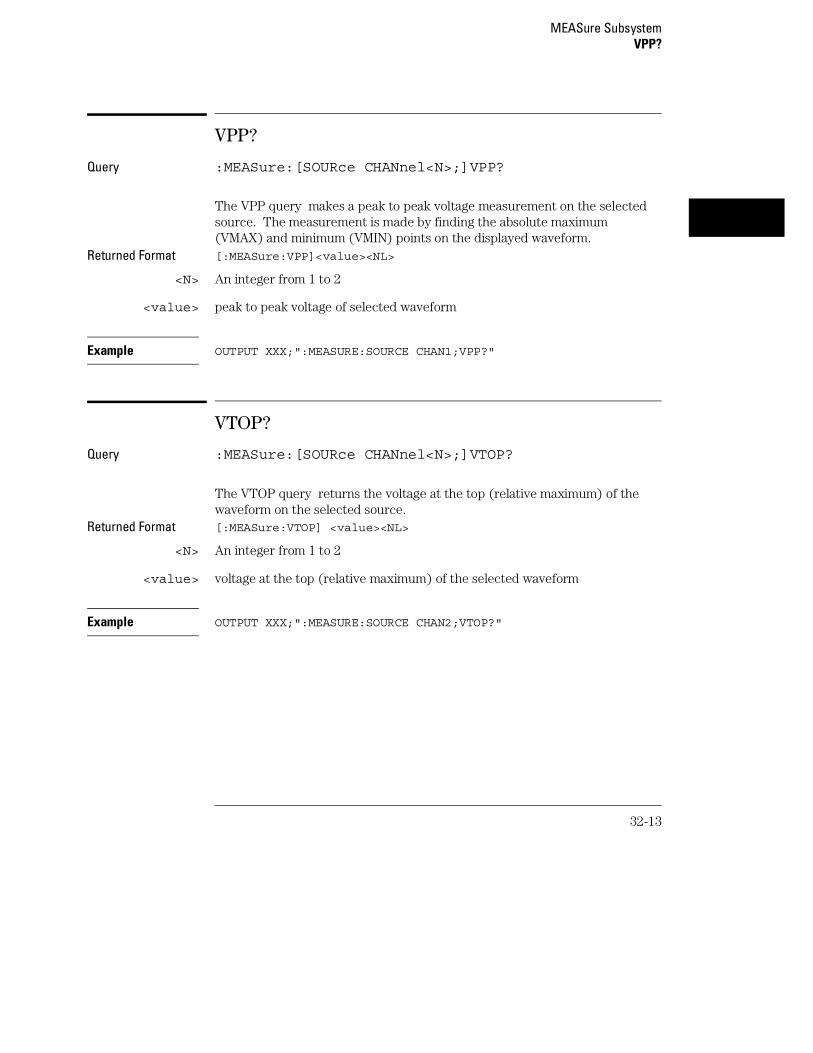
VPP?
Query :MEASure:[SOURce CHANnel<N>;]VPP?
The VPP query makes a peak to peak voltage measurement on the selectedsource. The measurement is made by finding the absolute maximum(VMAX) and minimum (VMIN) points on the displayed waveform.
Returned Format [:MEASure:VPP]<value><NL>
<N> An integer from 1 to 2
<value> peak to peak voltage of selected waveform
Example OUTPUT XXX;":MEASURE:SOURCE CHAN1;VPP?"
VTOP?
Query :MEASure:[SOURce CHANnel<N>;]VTOP?
The VTOP query returns the voltage at the top (relative maximum) of thewaveform on the selected source.
Returned Format [:MEASure:VTOP] <value><NL>
<N> An integer from 1 to 2
<value> voltage at the top (relative maximum) of the selected waveform
Example OUTPUT XXX;":MEASURE:SOURCE CHAN2;VTOP?"
MEASure SubsystemVPP?
32-13

32-14

33
TIMebase Subsystem

Introduction
The commands of the Timebase Subsystem control the Timebase,Trigger Delay Time, and the Timebase Mode. If TRIGgered mode is tobe used, ensure that the trigger specifications of the TriggerSubsystem have been set.
Refer to Figure 33-1 for the TIMebase Subsystem Syntax Diagram.
33-2

Figure 33-1
TIMebase Subsystem Syntax Diagram
Table 33-1 TIMebase Parameter Values
Parameter Value
delay_arg delay time in seconds, from -2500 seconds through +2500 seconds.The full range is available for panning the waveform when acquisitionis stopped. Refer to the User’s Reference Manual for a list of theavailable Delay Pre-trigger and Delay Post-trigger ranges whilerunning and making acquisitions.
range_arg a real number from 1 ns through 5 s
TIMebase Subsystem
33-3

DELay
Command :TIMebase:DELay <delay time>
The DELay command sets the time between the trigger and the center of thescreen.
<delay time> delay time in seconds, from -2500 seconds through +2500 seconds. The fullrange is available for panning the waveform when acquisition is stopped.Refer to the Oscilloscopes User’s Reference manual for a list of the availableDelay Pre-trigger and Delay Post-trigger ranges while running and makingacquisitions.
Example OUTPUT XXX;":TIM:DEL 2US"
Query :TIMebase:DELay?
The DELay query returns the current delay setting.Returned Format [:TIMebase DELay] <delay_time><NL>
Example OUTPUT XXX;":TIM:DEL?"
TIMebase SubsystemDELay
33-4

MODE
Command :TIMebase:MODE {TRIGgered|AUTO}
The MODE command sets the oscilloscope timebase to either Auto orTriggered mode. When the AUTO mode is chosen, the oscilloscope waitsapproximately 50 ms for a trigger to occur. If a trigger is not generatedwithin that time, then auto trigger is executed. If a signal is not applied tothe input, a baseline is displayed. If there is a signal at the input and thespecified trigger conditions have not been met within 50 ms, the waveformdisplay will not be synchronized to a trigger.
When the TRIGgered mode is chosen, the oscilloscope waits until a trigger isreceived before data is acquired. The TRIGgered mode should be used whenthe trigger source signal has less than a 20 Hz repetition rate, or when thetrigger events counter is set so that the number of trigger events would notoccur before 50 ms.
The Auto-Trig On field in the trigger menu is the same as the AUTO modeover GPIB or RS-232-C. The TRIGgered command is the same as theAuto-Trig Off on the front panel.
Example OUTPUT XXX;":TIM:MODE AUTO"
Query :TIMebase:MODE?
The MODE query returns the current Timebase mode.Returned Format [:TIMebase:MODE] {AUTO|TRIGgered}<NL>
Example OUTPUT XXX;":TIMebase:MODE?"
TIMebase SubsystemMODE
33-5

RANGe
Command :TIMebase:RANGe <range>
The RANGe command sets the full-scale horizontal time in seconds. TheRANGE value is ten times the value in the s/Div field.
<range> time in seconds
Example OUTPUT XXX;":TIMEBASE:RANGE 2US"
Query :TIMebase:RANGe?
The RANGe query returns the current setting.Returned Format [:TIMebase:RANGe] <range><NL>
Example OUTPUT XXX;":TIMEBASE:RANGE?"
TIMebase SubsystemRANGe
33-6

34
TRIGger Subsystem

Introduction
The commands of the Trigger Subsystem allow you to set all thetrigger conditions necessary for generating a trigger. Many of thecommands in the Trigger subsystem may be used in either the EDGEor the PATTern trigger mode. If a command is a valid command forthe chosen trigger mode, then that setting will be accepted by theoscilloscope. However, if the command is not valid for the triggermode, an error will be generated. None of the commands of thissubsystem (except Mode) are used in conjunction with Immediatetrigger mode.
See Figure 34-1 for the TRIGger Subsystem Syntax Diagram.
The EDGE Trigger Mode
In the EDGE trigger mode, the oscilloscope triggers on an edge of awaveform, specified by the SOURce, DELay, LEVel, and SLOPe commands.If a source is not specified, then the current source is assumed. The DELayvalue corresponds to the Count field displayed on the TRIGger menu.
The PATTern Trigger Mode
In the pattern trigger mode, the oscilloscope triggers when a pattern isgenerated using the CONDition, DELay, LEVel, LOGic and PATH commands.The CONDition command allows the oscilloscope to trigger when enteringthe specified pattern or exiting the pattern. The DELay value correspondsto the Count field displayed on the TRIGger menu. The LOGic commanddefines the pattern. The PATH command is used to change the triggerpattern and level. The path consists of two channels.
34-2

Figure 34-1
TRIGger Subsystem Syntax Diagram
TRIGger Subsystem
34-3

TRIGger Subsystem Syntax Diagram (Cont’d)
Table 34-1 TRIGger Parameter Values
Parameter Value
channel_# An integer from 1 to 2
count_# an integer from 1 through 32000
time a real number from 20 ns through 160 ms
figure 34-1
TRIGger Subsystem
34-4

CONDition
Command :TRIGger:[MODE PATTern;]CONDition{ENTer|EXIT|GT,<time>|LT,<time>|RANGe,<time>,<time>}
The CONDition command specifies if a trigger is to be generated on entry(ENTer) to a specific logic pattern, when exiting (EXIT) the specifiedpattern, or if a specified pattern duration (LT, GT, RANGe) is met. Thespecified pattern is defined by using the LOGic command.
When ENTer is chosen, the oscilloscope will trigger on the first transitionthat makes the pattern specification true for every input the number of timesspecified by the trigger event count (DELay command).
When EXIT is selected, the oscilloscope will trigger on the first transition thatcauses the pattern specification to be false after the pattern has been true forthe number of times specified by the trigger event count (DELay command).
When RANge is selected, the oscilloscope will trigger on the first transitionthat causes the pattern specification to be false, after the pattern has beentrue for the number of times specified by the trigger event count (DELAYcommand). The first event in the sequence will occur when the specifiedpattern is true for a time greater than that indicated by the first durationterm, and less than that indicated by the second duration term. All otherpattern true occurrences in the event count are independent of the patternduration range time.
When GT (greater than) is selected, the oscilloscope will trigger on the firsttransition that causes the pattern specification to be false, after the patternhas been true for the number of times specified by the trigger event count(DELAY command). The first event in the sequence will occur when thespecified pattern is true for a time greater than that indicated by the triggerspecification. All other pattern true occurrences in the event count areindependent of the pattern duration time.
TRIGger SubsystemCONDition
34-5

When LT (less than) is selected, the oscilloscope will trigger on the firsttransition that causes the pattern specification to be false, after the patternhas been true for the number of times specified by the trigger event count(DELAY command). The first event in the sequence will occur when thespecified pattern is true for a time less than that indicated by the triggerspecification. All other pattern true occurrences in the event count areindependent of the pattern duration time.
<time> real number between 20 ns and 160 ms
Example OUTPUT XXX;":TRIG:COND ENT"
The oscilloscope cannot be programmed for a pattern duration (GT, LT, orRANge) trigger if it is being armed by another module via an IMB (IntermoduleBus) measurement.
Query :TRIGger:CONDition?
The CONDition query returns the present condition.Returned Format [:TRIGger CONDition]
{ENTer|EXIT|GT,<time>|LT,<time>|RANGe,<time>,<time>}<NL>
Example OUTPUT XXX;":TRIG:COND?"
TRIGger SubsystemCONDition
34-6

DELay
Command :TRIGger:DELay [EVENt,]<count>
The DELay command is used to specify the number of events at whichtrigger occurs. The time delay (see TIMe:DELay) is counted after the eventsdelay. The DELay command cannot be used in the IMMediate trigger mode.
<count> integer from 1 to 32000
Example OUTPUT XXX;":TRIGGER:DELAY 5"
Query :TRIGger:DELay?
The DELay query returns the current trigger events count.Returned Format [:TRIGger:DELay] <count><NL>
Example OUTPUT XXX;":TRIG:DEL?"
TRIGger SubsystemDELay
34-7

LEVel
Command For EDGE trigger mode:
:TRIGger:[MODE EDGE;SOURce{CHANnel<N>;]LEVel<value>
For PATTern trigger mode:
:TRIGger:[MODE PATTern;PATH{CHANnel<N>};]LEVel<value>
The LEVel command sets the trigger level voltage for the selected source orpath. This command cannot be used in the IMMediate trigger mode. InEDGE trigger mode, the SOURce command is used; in PATTern mode, thetrigger PATH is used for the trigger level source. The LEVel command inPATTern trigger mode sets the high/low threshold for the pattern.
<N> An integer from 1 or 2
<value> Trigger level in volts
Example
For EDGE trigger mode:OUTPUT XXX;":TRIG:MODE EDGE;SOUR CHAN1;LEV 1.0"
For PATTern trigger mode:OUTPUT XXX;":TRIG:MODE PATTERN;PATH CHANNEL2;LEVEL 1.0"
TRIGger SubsystemLEVel
34-8

Query For EDGE trigger mode:
:TRIGger:[MODE EDGE;SOURce {CHANnel<N>};]LEVel?
For PATTern trigger mode:
:TRIGger:[MODE PATTern;PATH {CHANnel<N>};]LEVel?
The LEVel query returns the trigger level for the current path or source. Returned Format [:TRIGger:LEVel] <value><NL>
Example
For EDGE trigger mode:OUTPUT XXX;":TRIGGER:SOURCE CHANNEL1;LEVEL?"
For PATTern trigger mode:OUTPUT XXX;":TRIGGER:PATH CHANNEL1;LEVEL?"
TRIGger SubsystemLEVel
34-9

LOGic
Command :TRIGger:[MODE PATTern;PATH {CHANnel<N>};] LOGic{HIGH|LOW|DONTcare}
The LOGic command sets the logic for each trigger path in the PATTerntrigger mode. The choices are HIGH, LOW and DONTcare. The trigger levelset by the LEVel command determines logic high and low threshold levels.Any voltage higher than the present edge trigger level is considered a logichigh for that trigger path; any voltage lower than the trigger level isconsidered a logic low for that trigger path.
<N> An integer from 1 or 2
Example OUTPUT XXX;":TRIG:PATH CHAN1;LOG HIGH"
Query :TRIGger:LOGic?
The LOGic query returns the current logic of the previously selected triggeror path.
Returned Format [:TRIGger:LOGic] {HIGH|LOW|DONTcare}<NL>
Example OUTPUT XXX;":TRIG:MODE PATT;PATH CHAN1;LOG?"
TRIGger SubsystemLOGic
34-10

MODE
Command :TRIGger:MODE {EDGE|PATTern|IMMediate}
The MODE command allows you to select the trigger mode for theoscilloscope. The EDGE mode will trigger the oscilloscope on an edge whoseslope is determined by the SLOPe command at a voltage set by the LEVelcommand. The PATTern mode will trigger the oscilloscope on entering orexiting a specified pattern of the two internal channels and external trigger.In the IMMediate trigger mode, the oscilloscope goes to a freerun mode anddoes not wait for a trigger. Generally, the IMMediate mode is used inintermodule applications.
Example OUTPUT XXX;":TRIGGER:MODE PATTERN"
Query :TRIGger:MODE?
The MODE query returns the current trigger mode selection.Returned Format [:TRIGger:MODE] {EDGE|PATTern|IMMediate}<NL>
Example OUTPUT XXX;":TRIGGER:MODE?"
TRIGger SubsystemMODE
34-11

PATH
Command :TRIGger:[MODE PATTern;]PATH {CHANnel<N>}
The PATH command is used to select a trigger path for the subsequentLOGic and LEVel commands. This command can only be used in thePATTern trigger mode.
<N> An integer from 1 or 2
Example OUTPUT XXX;":TRIGGER:PATH CHANNEL1"
Query :TRIGger:PATH?
The PATH query returns the current trigger path.Returned Format [:TRIGger PATH] {CHANnel<N>}<NL>
Example OUTPUT XXX;":TRIGGER:PATH?"
SLOPe
Command :TRIGger:[MODE EDGE;SOURce {CHANnel<N>};]SLOPe{POSitive|NEGative}
The SLOPe command selects the trigger slope for the specified triggersource. This command can only be used in the EDGE trigger mode.
<N> 1 or 2
Example OUTPUT XXX;":TRIG:SOUR CHAN1;SLOP POS"
TRIGger SubsystemPATH
34-12

Query :TRIGger:SLOPe?
The SLOPe query returns the slope of the current trigger source.Returned Format [:TRIGger:SLOPe] {POSitive|NEGative}<NL>
Example OUTPUT XXX;":TRIG:SOUR CHAN1;SLOP?"
SOURce
Command :TRIGger:[MODE EDGE;]SOURce {CHANnel<N>}
The SOURce command is used to select the trigger source and is used for anysubsequent SLOPe and LEVel commands. This command can only be used inthe EDGE trigger mode. It is the equivalent to the PATH command for thePATTern trigger mode.
<N> An integer from 1 or 2
Example OUTPUT XXX;":TRIG:SOUR CHAN1"
Query :TRIGger:SOURce?
The SOURce query returns the current trigger source.Returned Format [:TRIGger:SOURce] {CHANnel<N>}<NL>
Example OUTPUT XXX;":TRIGGER:SOURCE?"
TRIGger SubsystemSOURce
34-13

34-14

35
WAVeform Subsystem

Introduction
The commands of the Waveform subsystem are used to transferwaveform data from the oscilloscope to a controller. The waveformrecord is actually contained in two portions; the waveform data andpreamble. The waveform data is the actual data acquired for eachpoint when a DIGitize command is executed. The preamble containsthe information for interpreting waveform data. Data in the preambleincludes number of points acquired, format of acquired data, averagecount and the type of acquired data. The preamble also contains theX and Y increments, origins, and references for the acquired data fortranslation to time and voltage values.
The values set in the preamble are based on the settings of thevariables in the Acquire, Waveform, Channel, and Timebasesubsystems. The Acquire subsystem determines the acquisition typeand the average count, the Waveform subsystem sets the number ofpoints and format mode for sending waveform data over the remoteinterface and the Channel and Timebase subsystems set all the X - Yparameters.
Refer to Figure 35-3 for the Waveform Subsystem Syntax Diagram.
Data Acquisition Types
The two acquisition types that may be chosen are Normal or Average.
Normal Mode
In the Normal mode, with ACCumulate command OFF, the oscilloscopeacquires waveform data and then displays the waveform. When theoscilloscope takes a new acquisition, the previously acquired waveform iserased from the display and replaced by the newly acquired waveform.
When the ACCumulate is set ON, the oscilloscope displays all the waveformacquisitions without erasing the previously acquired waveform.
35-2

Average Mode
In the Average mode, the oscilloscope averages the data points on thewaveform with previously acquired data. Averaging helps eliminate randomnoise from the displayed waveform. In this mode ACCumulate is set to OFF.When Average mode is selected the number of averages must also bespecified using the COUNt command. Previously displayed waveform data iserased from the display and the newly averaged waveform is displayed.
WAVeform Subsystem
35-3

Format for Data Transfer
There are three formats for transferring waveform data over the remoteinterface. These formats are WORD, BYTE, or ASCII.
WORD and BYTE formatted waveform records are transmitted using thearbitrary block program data format specified in IEEE-488.2. When you usethis format, the ASCII character string "#8 <DD...D>" is sent before the actualdata.
The <D>’s are eight ASCII numbers which indicate how many data bytes willfollow.
For example, if 8192 points of data are to be transmitted, the ASCII string#800008192 would be sent.
BYTE Format
In BYTE format, the seven least significant bits represent the waveform data.This means that the possible range of data is divided into 128 verticalincrements. The most significant bit is not used. If all "1"s are returned inthe seven least significant bits, the waveform is clipped at the top of thescreen. If all "0"s are returned, the waveform is clipped at the bottom of thescreen (see figure 35-1).
Figure 35-1
Byte Data Structure
The data returned in BYTE format is the same for either Normal or Averageacquisition types. The data transfer rate in this format is faster than theother two formats.
WAVeform SubsystemFormat for Data Transfer
35-4

WORD Format
Word data is two bytes wide with the most significant byte of each wordbeing transmitted first. In WORD format, the 15 least significant bitsrepresent the waveform data. The possible range of data is divided into32768 vertical increments. The WORD data structure for normal and averageacquisition types are shown in figure 35-2. If all "1’s are returned in the 15least significant bits, the waveform is clipped at the top of the screen. If all"0’s are returned in the 15 least significant bits, the waveform is clipped atthe bottom of the screen.
WORD (and ASCII) format data is more accurate than BYTE format data.BYTE format simply truncates the 8 least significant bits of WORD formatdata.
Figure 35-2
Word Data Structure
ASCII Format
ASCII formatted waveform records are transmitted one value at a time,separated by a comma. The data values transmitted are the same as wouldbe sent in the WORD format except that they are converted to an integerASCII format (six or less characters) before being transmitted. The headerbefore the data is not included in this format.
WAVeform SubsystemFormat for Data Transfer
35-5

Data Conversion
Data sent from the oscilloscope is raw data and must be scaled for usefulinterpretation. The values used to interpret the data are the X and Yreferences, X and Y origins, and X and Y increments. These values are readfrom the waveform preamble (see the PREamble command) or by thequeries of these values.
Conversion from Data Value to Voltage
The formula to convert a data value returned by the instrument to a voltageis:
voltage = [(data value - yreference) * yincrement] + yorigin
Conversion from Data Value to Time
The time value of a data point can be determined by the position of the datapoint. As an example, the third data point sent with XORIGIN = 16ns,XREFERENCE = 0 and XINCREMENT = 2ns. Using the formula:
time = [(data point number - xreference) * xincrement] + xorigin
would result in the following calculation:
time = [(3 - 0) * 2ns] + 16ns = 22ns.
Conversion from Data Value to Trigger Point
The trigger data point can be determined by calculating the closest data pointto time 0.
WAVeform SubsystemData Conversion
35-6

WAVeform Subsystem Syntax Diagram
Figure 35-3
WAVeform SubsystemData Conversion
35-7

Figure 35-3
WAVeform Subsystem Syntax Diagram (Cont’d)
Table 35-1 WAVeform Parameter Values
Parameter Value
channel_# an integer from 1 to 2
WAVeform SubsystemData Conversion
35-8
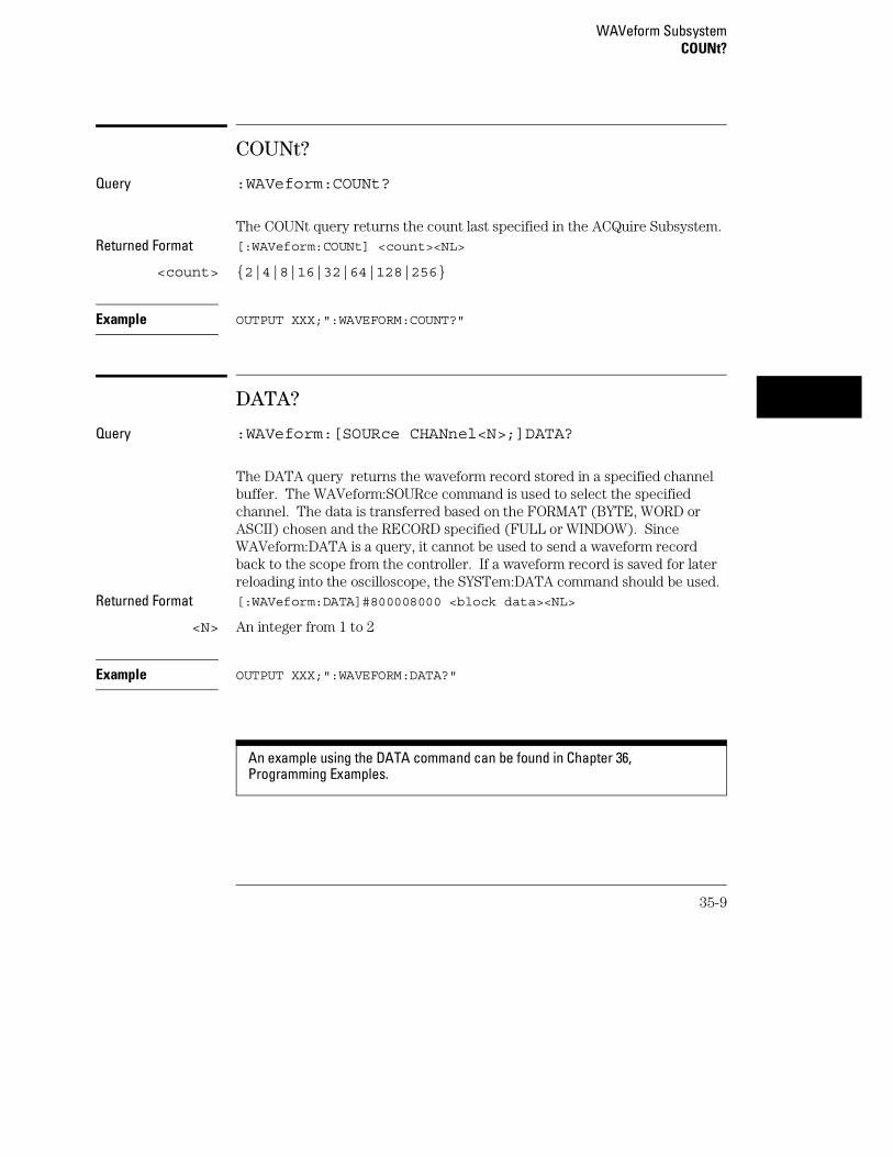
COUNt?
Query :WAVeform:COUNt?
The COUNt query returns the count last specified in the ACQuire Subsystem.Returned Format [:WAVeform:COUNt] <count><NL>
<count> {2|4|8|16|32|64|128|256}
Example OUTPUT XXX;":WAVEFORM:COUNT?"
DATA?
Query :WAVeform:[SOURce CHANnel<N>;]DATA?
The DATA query returns the waveform record stored in a specified channelbuffer. The WAVeform:SOURce command is used to select the specifiedchannel. The data is transferred based on the FORMAT (BYTE, WORD orASCII) chosen and the RECORD specified (FULL or WINDOW). SinceWAVeform:DATA is a query, it cannot be used to send a waveform recordback to the scope from the controller. If a waveform record is saved for laterreloading into the oscilloscope, the SYSTem:DATA command should be used.
Returned Format [:WAVeform:DATA]#800008000 <block data><NL>
<N> An integer from 1 to 2
Example OUTPUT XXX;":WAVEFORM:DATA?"
An example using the DATA command can be found in Chapter 36,Programming Examples.
WAVeform SubsystemCOUNt?
35-9

FORMat
Command :WAVeform:FORMat {BYTE|WORD|ASCii}
The FORMat command specifies the data transmission mode of waveformdata over the remote interface.
Example OUTPUT XXX;":WAV:FORM WORD"
Query :WAVeform:FORMat?"
The FORMat query returns the currently specified format.Returned Format [:WAVeform:FORMat]{BYTE|WORD|ASCii}<NL>
Example OUTPUT XXX;":WAVEFORM:FORMAT?"
POINts?
Query :WAVeform:POINts?
When WAVeform RECord is set to FULL, the POINts query always returns avalue of 8000 points. When WAVeform RECord is set to WINdow, then thequery returns the number of points displayed on screen.
Returned Format [:WAVeform:POINts] <points><NL>
<points> number of points depending on the setting of the WAVeform RECordcommand
Example OUTPUT XXX;":WAVEFORM:POINTS?"
WAVeform SubsystemFORMat
35-10

PREamble?
Query :WAVeform[:SOURce CHANnel<N>;]PREamble?
The PREamble query returns the preamble of the specified channel. Thechannel is specified using the SOURCE command.
Returned Format [:WAVeform:PREamble]
<format>, (0 = ASCII, 1 = BYTE, 2 = WORD,)<type>, (1 = Normal, 2 = Average)<points >,<count >,<Xincrement >,<Xorigin >,<Xreference >,<Yincrement >,<Yorigin >,<Yreference ><NL>
<N> An integer from 1 to 2
Example OUTPUT XXX;":WAVEFORM:PREAMBLE?"
For more information on the fields in PREamble, see the commands which querythe individual fields. For example, see the FORmat command for an explanationof the format field.
WAVeform SubsystemPREamble?
35-11
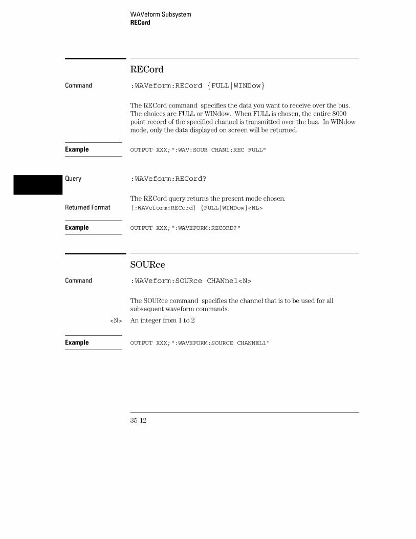
RECord
Command :WAVeform:RECord {FULL|WINDow}
The RECord command specifies the data you want to receive over the bus.The choices are FULL or WINdow. When FULL is chosen, the entire 8000point record of the specified channel is transmitted over the bus. In WINdowmode, only the data displayed on screen will be returned.
Example OUTPUT XXX;":WAV:SOUR CHAN1;REC FULL"
Query :WAVeform:RECord?
The RECord query returns the present mode chosen.Returned Format [:WAVeform:RECord] {FULL|WINDow}<NL>
Example OUTPUT XXX;":WAVEFORM:RECORD?"
SOURce
Command :WAVeform:SOURce CHANnel<N>
The SOURce command specifies the channel that is to be used for allsubsequent waveform commands.
<N> An integer from 1 to 2
Example OUTPUT XXX;":WAVEFORM:SOURCE CHANNEL1"
WAVeform SubsystemRECord
35-12

Query :WAVeform:SOURce?
The SOURce query returns the presently selected channel.Returned Format [:WAVeform:SOURce] CHANnel<N><NL>
Example OUTPUT XXX;":WAVEFORM:SOURCE?"
SPERiod?
Query :WAVeform:SPERiod?
The SPERiod query returns the present sampling period. The sample periodis determined by the DELay and the RANGe commands of the TIMEbasesubsystem.
Returned Format [:WAVeform:SPERiod] <period><NL>
<period> time in seconds
Example OUTPUT XXX;":WAVEFORM:SPERIOD?"
TYPE?
Query :WAVeform:TYPE?
The TYPE query returns the presently acquisition type (normal or average).The acquisition type is specified in the ACQuire Subsystem using theACQuire TYPE command.
Returned Format [:WAVeform:TYPE]{NORMal|AVERage}<NL>
Example OUTPUT XXX;":WAVEFORM:TYPE?"
WAVeform SubsystemSPERiod?
35-13

VALid?
Query :WAVeform:VALid?
The VALid query checks the oscilloscope for acquired data. If ameasurement is completed, and data has been acquired by all channels, thenthe query reports a 1. A 0 is reported if no data has been acquired for thelast acquisition.
Returned Format [:WAVeform:VALid] {0|1}<NL>
0 No data acquired
1 Data has been acquired
Example OUTPUT XXX;":WAVEFORM:VALID?"
WAVeform SubsystemVALid?
35-14

XINCrement?
Query :WAVeform:XINCrement?
The XINCrement query returns the X-increment currently in the preamble.This value is the time difference between the consecutive data points.X-increment is determined by the RECord mode as follows:
• In FULL record mode, the X-increment equals the time period betweendata samples (or sample period).
• In WINDow record mode, the X-increment is the time between data pointson the logic analyzer front panel. The X-increment for WINDow recorddata will be less than or equal to the sample period.
Returned Format [:WAVeform:XINCrement]<value><NL>
<value> X-increment value currently in preamble
Example OUTPUT XXX;":WAVEFORM:XINCREMENT?"
WAVeform SubsystemXINCrement?
35-15

XORigin?
Query :WAVeform:[SOURce CHANnel<N>;]XORigin?
The XORigin query returns the X-origin value currently in the preamble.The value represents the time of the first data point in memory with respectto the trigger point.
Returned Format [:WAVeform:XORigin]<value><NL>
<N> An integer from 1 to 2
<value> X-origin currently in preamble
Example OUTPUT XXX;":WAV:XOR?"
XREFerence?
Query :WAVeform:XREFerence?
The XREFerence query returns the current X-reference value in thepreamble. This value specifies the X-value of the first data point in memoryand is always 0.
Returned Format [:WAVeform:XREFerence]<value><NL>
<value> X-reference value in the preamble
Example OUTPUT XXX;":WAVEFORM:XREFERENCE?"
WAVeform SubsystemXORigin?
35-16

YINCrement?
Query :WAVeform:[SOURce CHANnel<N>;]YINCrement?
The YINCrement query returns the Y-increment value currently in thepreamble. This value is the voltage difference between consecutive datavalues.
Returned Format [:WAVeform:YINCrement]<value><NL>
<N> An integer from 1 to 2
<value> Y-increment value in preamble
Example OUTPUT XXX;":WAVEFORM:YINCREMENT?"
YORigin?
Query :WAVeform:[SOURce CHANnel<N>;]YORigin?
The YORigin query returns the Y-origin value currently in the preamble.This value is the voltage at center screen.
Returned Format [:WAVeform:YORigin]<value><NL>
<N> An integer from 1 to 2
<value> Y-origin value in preamble
Example OUTPUT XXX;":WAVEFORM:YORIGIN?"
WAVeform SubsystemYINCrement?
35-17

YREFerence?
Query :WAVeform:YREFerence?
The YREFerence query returns the Y-reference value currently in thepreamble. This value specifies the data value at center screen where Y-originoccurs.
Returned Format [:WAVeform:YREFerence]<value><NL>
<value> Y-reference data value in preamble
Example OUTPUT XXX;":WAVEFORM:YREFERENCE?"
WAVeform SubsystemYREFerence?
35-18

Part 5
Programming Examples


36
Programming Examples

Introduction
This chapter contains short, usable, and tested program examplesthat cover the most asked for examples. The examples are written inHP Basic 6.0.
• Making a timing analyzer measurement
• Making a state analyzer measurement
• Making a state compare measurement
• Transferring logic analyzer configuration between the logic analyzerand the controller
• Transferring logic analyzer data between the logic analyzer and thecontroller
• Checking for measurement completion
• Sending queries to the logic analyzer
• Getting ASCII data with PRINt? All query
• Reading a disk catalog
• Printing to the disk using PRINT? ALL
• Transferring waveform data in Byte format
• Transferring waveform data in Word format
• Using AUToscale and the MEASure:ALL? Query
• Using subroutines in a measurement program
36–2

Making a Timing analyzer measurement
This program sets up the logic analyzer to make a simple timing analyzermeasurement. This example can be used with E2433-60004 Logic AnalyzerTraining board to acquire and display the output of the ripple counter. It canalso be modified to make any timing analyzer measurement.
10 ! ****************** TIMING ANALYZER EXAMPLE ******************20 ! for the 1660A Logic Analyzer30 !40 ! **************************************************************50 ! Select the module slot in which the logic analyzer is installed.60 ! Always a 1 for the 1660-series logic analyzers.70 !80 OUTPUT 707;":SELECT 1"90 !100 ! **************************************************************110 ! Name Machine 1 "TIMING," configure Machine 1 as a timing analyzer,120 ! and assign pod 1 to Machine 1.130 !140 OUTPUT 707;":MACH1:NAME ’TIMING’"150 OUTPUT 707;":MACH1:TYPE TIMING"160 OUTPUT 707;":MACH1:ASSIGN 1"170 !180 ! **************************************************************190 ! Make a label "COUNT," give the label a positive polarity, and200 ! assign the lower 8 bits.210 !220 OUTPUT 707;":MACHINE1:TFORMAT:REMOVE ALL"230 OUTPUT 707;":MACH1:TFORMAT:LABEL ’COUNT’,POS,0,0,#B0000000011111111"240 !250 ! **************************************************************260 ! Specify FF hex for resource term A, which is the default trigger termfor270 ! the timing analyzer.280 !290 OUTPUT 707;":MACH1:TTRACE:TERM A, ’COUNT’, ’#HFF’"300 !310 ! ***************************************************************320 ! Remove any previously inserted labels, insert the "COUNT"330 ! label, change the seconds-per-division to 100 ns, and display the340 ! waveform menu.
Programming ExamplesMaking a Timing analyzer measurement
36–3
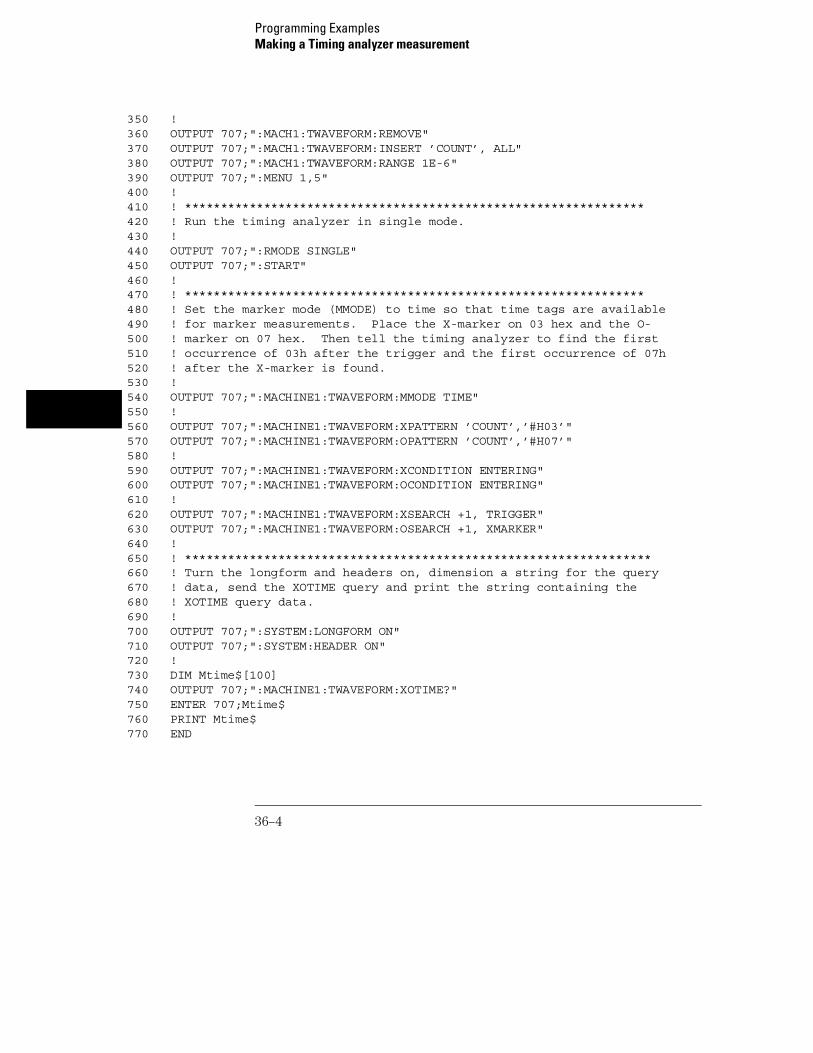
350 !360 OUTPUT 707;":MACH1:TWAVEFORM:REMOVE"370 OUTPUT 707;":MACH1:TWAVEFORM:INSERT ’COUNT’, ALL"380 OUTPUT 707;":MACH1:TWAVEFORM:RANGE 1E-6"390 OUTPUT 707;":MENU 1,5"400 !410 ! ****************************************************************420 ! Run the timing analyzer in single mode.430 !440 OUTPUT 707;":RMODE SINGLE"450 OUTPUT 707;":START"460 !470 ! ****************************************************************480 ! Set the marker mode (MMODE) to time so that time tags are available490 ! for marker measurements. Place the X-marker on 03 hex and the O-500 ! marker on 07 hex. Then tell the timing analyzer to find the first510 ! occurrence of 03h after the trigger and the first occurrence of 07h520 ! after the X-marker is found.530 !540 OUTPUT 707;":MACHINE1:TWAVEFORM:MMODE TIME"550 !560 OUTPUT 707;":MACHINE1:TWAVEFORM:XPATTERN ’COUNT’,’#H03’"570 OUTPUT 707;":MACHINE1:TWAVEFORM:OPATTERN ’COUNT’,’#H07’"580 !590 OUTPUT 707;":MACHINE1:TWAVEFORM:XCONDITION ENTERING"600 OUTPUT 707;":MACHINE1:TWAVEFORM:OCONDITION ENTERING"610 !620 OUTPUT 707;":MACHINE1:TWAVEFORM:XSEARCH +1, TRIGGER"630 OUTPUT 707;":MACHINE1:TWAVEFORM:OSEARCH +1, XMARKER"640 !650 ! *****************************************************************660 ! Turn the longform and headers on, dimension a string for the query670 ! data, send the XOTIME query and print the string containing the680 ! XOTIME query data.690 !700 OUTPUT 707;":SYSTEM:LONGFORM ON"710 OUTPUT 707;":SYSTEM:HEADER ON"720 !730 DIM Mtime$[100]740 OUTPUT 707;":MACHINE1:TWAVEFORM:XOTIME?"750 ENTER 707;Mtime$760 PRINT Mtime$770 END
Programming ExamplesMaking a Timing analyzer measurement
36–4

Making a State analyzer measurement
This state analyzer program selects the 1660-series logic analyzer, displaysthe configuration menu, defines a state machine, displays the state triggermenu, sets a state trigger for multilevel triggering. This program then startsa single acquisition measurement while checking for measurementcompletion.
This program is written in such a way you can run it with the E2433-60004Logic Analyzer Training Board. This example is the same as the "MultilevelState Triggering" example in chapter 9 of the E2433-90910 Logic Analyzer
Training Guide.
10 ! ******************** STATE ANALYZER EXAMPLE *************************20 ! for the 1660-series Logic Analyzers30 !40 ! ****************** SELECT THE LOGIC ANALYZER **********************50 ! Select the module slot in which the logic analyzer is installed.60 ! Always a 1 for the 1660-series logic analyzers.70 !80 OUTPUT 707;":SELECT 1"90 !100 ! ******************** CONFIGURE THE STATE ANALYZER **********************110 ! Name Machine 1 "STATE," configure Machine 1 as a state analyzer, assign120 ! pod 1 to Machine 1, and display System Configuration menu of the130 ! logic analyzer.140 !150 OUTPUT 707;":MACHINE1:NAME ’STATE’"160 OUTPUT 707;":MACHINE1:TYPE STATE"170 OUTPUT 707;":MACHINE1:ASSIGN 1"180 OUTPUT 707;":MENU 1,0"190 !200 ! ******************* SETUP THE FORMAT SPECIFICATION *********************210 ! Make a label "SCOUNT," give the label a positive polarity, and220 ! assign the lower 8 bits.230 !240 OUTPUT 707;":MACHINE1:SFORMAT:REMOVE ALL"250 OUTPUT 707;":MACHINE1:SFORMAT:LABEL ’SCOUNT’, POS, 0,0,255"260 !270 ! ******************* SETUP THE TRIGGER SPECIFICATION ********************280 ! The trigger specification will use five sequence levels with the trigger290 ! level on level four. Resource terms A through E, and RANGE1 will be300 ! used to store only desired counts from the 8-bit ripple counter.
Programming ExamplesMaking a State analyzer measurement
36–5

310 !320 ! Display the state trigger menu.330 !340 OUTPUT 707;":MENU 1,3"350 !360 ! Create a 5 level trigger specification with the trigger on the370 ! fourth level.380 !390 OUTPUT 707;":MACHINE1:STRIGGER:SEQUENCE 5,4"400 !410 ! Define pattern terms A, B, C, D, and E to be 11, 22, 33, 44 and 59420 ! decimal respectively.430 !440 OUTPUT 707;":MACHINE1:STRIGGER:TERM A,’SCOUNT’,’11’"450 OUTPUT 707;":MACHINE1:STRIGGER:TERM B,’SCOUNT’,’22’"460 OUTPUT 707;":MACHINE1:STRIGGER:TERM C,’SCOUNT’,’33’"470 OUTPUT 707;":MACHINE1:STRIGGER:TERM D,’SCOUNT’,’44’"480 OUTPUT 707;":MACHINE1:STRIGGER:TERM E,’SCOUNT’,’59’"490 !500 ! Define a Range having a lower limit of 50 and an upper limit of 58.510 !520 OUTPUT 707;":MACHINE1:STRIGGER:RANGE1 ’SCOUNT’,’50’,’58’"530 !540 ! ***************** CONFIGURE SEQUENCE LEVEL 1 ***************************550 ! Store NOSTATE in level 1 and Then find resource term "A" once.560 !570 OUTPUT 707;":MACHINE1:STRIGGER:STORE1 ’NOSTATE’"580 OUTPUT 707;":MACHINE1:STRIGGER:FIND1 ’A’,1"590 !600 ! ***************** CONFIGURE SEQUENCE LEVEL 2 ***************************610 ! Store RANGE1 in level 2 and Then find resource term "E" once.620 !630 OUTPUT 707;":MACHINE1:STRIGGER:STORE2 ’IN_RANGE1’"640 OUTPUT 707;":MACHINE1:STRIGGER:FIND2 ’E’,1"650 !660 ! ***************** CONFIGURE SEQUENCE LEVEL 3 ***************************670 ! Store NOSTATE in level 3 and Then find term "B" once.680 !690 OUTPUT 707;":MACHINE1:STRIGGER:STORE3 ’NOSTATE’"700 OUTPUT 707;":MACHINE1:STRIGGER:FIND3 ’B’,1"710 !720 ! ***************** CONFIGURE SEQUENCE LEVEL 4 ***************************730 ! Store a combination of resource terms (C or D or RANGE1) in level 4 and740 ! Then Trigger on resource term "E."750 !
Programming ExamplesMaking a State analyzer measurement
36–6
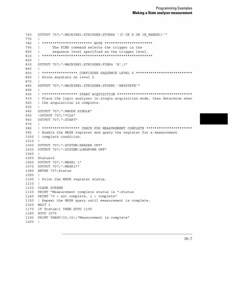
760 OUTPUT 707;":MACHINE1:STRIGGER:STORE4 ’(C OR D OR IN_RANGE1)’"770 !780 ! ************************ NOTE ***********************790 ! The FIND command selects the trigger in the800 ! sequence level specified as the trigger level.810 ! *****************************************************820 !830 OUTPUT 707;":MACHINE1:STRIGGER:FIND4 ’E’,1"840 !850 ! ***************** CONFIGURE SEQUENCE LEVEL 5 ***************************860 ! Store anystate on level 5870 !880 OUTPUT 707;":MACHINE1:STRIGGER:STORE5 ’ANYSTATE’"890 !900 ! ***************** START ACQUISITION ************************************910 ! Place the logic analyzer in single acquisition mode, then determine when920 ! the acquisition is complete.930 !940 OUTPUT 707;":RMODE SINGLE"950 !OUTPUT 707;"*CLS"960 OUTPUT 707;":START"970 !980 ! ****************** CHECK FOR MEASUREMENT COMPLETE **********************990 ! Enable the MESR register and query the register for a measurement1000 ! complete condition.1010 !1020 OUTPUT 707;":SYSTEM:HEADER OFF"1030 OUTPUT 707;":SYSTEM:LONGFORM OFF"1040 !1050 Status=01060 OUTPUT 707;":MESE1 1"1070 OUTPUT 707;":MESR1?"1080 ENTER 707;Status1090 !1100 ! Print the MESR register status.1110 !1120 CLEAR SCREEN1130 PRINT "Measurement complete status is ";Status1140 PRINT "0 = not complete, 1 = complete"1150 ! Repeat the MESR query until measurement is complete.1160 WAIT 11170 IF Status=1 THEN GOTO 11901180 GOTO 10701190 PRINT TABXY(30,15);"Measurement is complete"1200 !
Programming ExamplesMaking a State analyzer measurement
36–7

1210 ! ************************ VIEW THE RESULTS *****************************1220 ! Display the State Listing and select a line number in the listing that1230 ! allows you to see the beginning of the listing on the logic analyer1240 ! display.1250 !1260 OUTPUT 707;":MACHINE1:SLIST:COLUMN 1, ’SCOUNT’, DECIMAL"1270 OUTPUT 707;":MENU 1,7"1280 OUTPUT 707;":MACHINE1:SLIST:LINE -16"1290 !1300 END
Programming ExamplesMaking a State analyzer measurement
36–8

Making a State Compare measurement
This program example acquires a state listing, copies the listing to thecompare listing, acquires another state listing, and compares both listings tofind differences.
This program is written in such a way you can run it with the E2433-60004Logic Analyzer Training Board. This example is the same as the "StateCompare" example in chapter 3 of the E2433-90910 Logic Analyzer
Training Guide.
10 ! *********** STATE COMPARE EXAMPLE ********************************20 ! for the 1660-Series Logic Analyzers30 !40 !50 !************** SELECT THE LOGIC ANALYZER ************************60 ! Select the module slot in which the logic analyzer is installed.70 ! Always a 1 for the 1660A-series logic analyzers.80 !90 OUTPUT 707;":SELECT 1"100 !110 !************** CONFIGURE THE STATE ANALYZER ***********************120 ! Name Machine 1 "STATE," configure Machine 1 as a state analyzer, and130 ! assign pod 1 to Machine 1.140 !150 OUTPUT 707;":MACHINE1:NAME ’STATE’"160 OUTPUT 707;":MACHINE1:TYPE STATE"170 OUTPUT 707;":MACHINE1:ASSIGN 1"180 !190 ! ******************************************************************200 ! Remove all labels previously set up, make a label "SCOUNT," specify210 ! positive logic, and assign the lower 8 bits of pod 1 to the label.220 !230 OUTPUT 707;":MACHINE1:SFORMAT:REMOVE ALL"240 OUTPUT 707;":MACHINE1:SFORMAT:LABEL ’SCOUNT’, POS, 0,0,255"250 !260 ! ******************************************************************270 ! Make the "J" clock the Master clock and specify the falling edge.280 !290 OUTPUT 707;":MACHINE1:SFORMAT:MASTER J, FALLING"300 !310 ! ******************************************************************320 ! Specify two sequence levels, the trigger sequence level, specify
Programming ExamplesMaking a State Compare measurement
36–9

330 ! FF hex for the "a" term which will be the trigger term, and store340 ! no states until the trigger is found.350 !360 OUTPUT 707;":MACHINE1:STRIGGER:SEQUENCE 2,1"370 OUTPUT 707;":MACHINE1:STRIGGER:TERM A,’SCOUNT’,’#HFF’"380 OUTPUT 707;":MACHINE1:STRIGGER:STORE1 ’NOSTATE’"390 OUTPUT 707;":MENU 1,3"400 !410 ! ******************************************************************420 ! Change the displayed menu to the state listing and start the state430 ! analyzer in repetitive mode.440 !450 OUTPUT 707;":MENU 1,7"460 OUTPUT 707;":RMODE REPETITIVE"470 OUTPUT 707;":START"480 !490 ! ******************************************************************500 ! The logic analyzer is now running in the repetitive mode510 ! and will remain in repetitive until the STOP command is sent.520 !530 PRINT "The logic analyzer is now running in the repetitive mode"540 PRINT "and will remain in repetitive until the STOP command is sent."550 PRINT 560 PRINT "Press CONTINUE"570 PAUSE580 !590 !***********************************************************************600 ! Stop the acquisition and copy the acquired data to the compare reference610 ! listing.620 !630 OUTPUT 707;":STOP"640 OUTPUT 707;":MENU 1,10"650 OUTPUT 707;":MACHINE1:COMPARE:MENU REFERENCE"660 OUTPUT 707;":MACHINE1:COMPARE:COPY"670 !680 ! The logic analyzer acquistion is now stopped, the Compare menu690 ! is displayed, and the data is now in the compare reference700 ! listing.710 !720 !***********************************************************************730 ! Display line 4090 of the compare listing and start the analyzer740 ! in a repetitive mode.750 !760 OUTPUT 707;":MACHINE1:COMPARE:LINE 4090"770 OUTPUT 707;":START"
Programming ExamplesMaking a State Compare measurement
36–10

780 !790 ! Line 4090 of the listing is now displayed at center screen800 ! in order to show the last four states acquired. In this810 ! example, the last four states are stable. However, in some820 ! cases, the end points of the listing may vary thus causing830 ! a false failure in compare. To eliminate this problem, a840 ! partial compare can be specified to provide predicable end850 ! points of the data.860 !870 PRINT "Press CONTINUE to send the STOP command."880 PAUSE890 OUTPUT 707;":STOP"900 !910 !************************************************************************920 ! The end points of the compare can be fixed to prevent false failures.930 ! In addition, you can use partial compare to compare only sections940 ! of the state listing you are interested in comparing.950 !960 OUTPUT 707;":MACHINE1:COMPARE:RANGE PARTIAL, 0, 508"970 !980 ! The compare range is now from line 0 to +508990 !1000 !************************************************************************1010 ! Change the Glitch jumper settings on the training board so that the1020 ! data changes, reacquire the data and compare which states are different.1030 PRINT "Change the glitch jumper settings on the training board so thatthe"1040 PRINT "data changes, reacquire the data and compare which states aredifferent."1050 !1060 PRINT "Press CONTINUE when you have finished changing the jumper."1070 !1080 PAUSE1090 !1100 !************************************************************************1110 ! Start the logic analyzer to acquire new data and then stop it to compare1120 ! the data. When the acquistion is stopped, the Compare Listing Menu will1130 ! be displayed.1140 !1150 OUTPUT 707;":START"1160 OUTPUT 707;":STOP"1170 OUTPUT 707;":MENU 1,10"1180 !1190 !************************************************************************1200 ! Dimension strings in which the compare find query (COMPARE:FIND?)
Programming ExamplesMaking a State Compare measurement
36–11
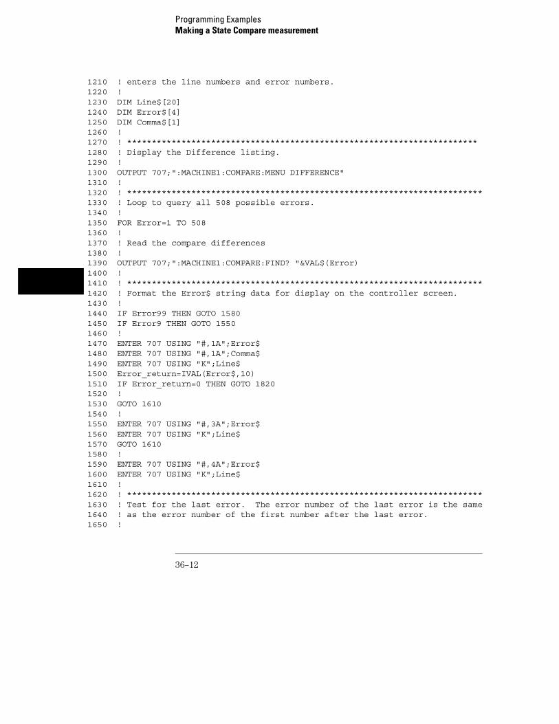
1210 ! enters the line numbers and error numbers.1220 !1230 DIM Line$[20]1240 DIM Error$[4]1250 DIM Comma$[1]1260 !1270 ! ***********************************************************************1280 ! Display the Difference listing.1290 !1300 OUTPUT 707;":MACHINE1:COMPARE:MENU DIFFERENCE"1310 !1320 ! ************************************************************************1330 ! Loop to query all 508 possible errors.1340 !1350 FOR Error=1 TO 5081360 !1370 ! Read the compare differences1380 !1390 OUTPUT 707;":MACHINE1:COMPARE:FIND? "&VAL$(Error)1400 !1410 ! ************************************************************************1420 ! Format the Error$ string data for display on the controller screen.1430 !1440 IF Error99 THEN GOTO 15801450 IF Error9 THEN GOTO 15501460 !1470 ENTER 707 USING "#,1A";Error$1480 ENTER 707 USING "#,1A";Comma$1490 ENTER 707 USING "K";Line$1500 Error_return=IVAL(Error$,10)1510 IF Error_return=0 THEN GOTO 18201520 !1530 GOTO 16101540 !1550 ENTER 707 USING "#,3A";Error$1560 ENTER 707 USING "K";Line$1570 GOTO 16101580 !1590 ENTER 707 USING "#,4A";Error$1600 ENTER 707 USING "K";Line$1610 !1620 ! ************************************************************************1630 ! Test for the last error. The error number of the last error is the same1640 ! as the error number of the first number after the last error.1650 !
Programming ExamplesMaking a State Compare measurement
36–12
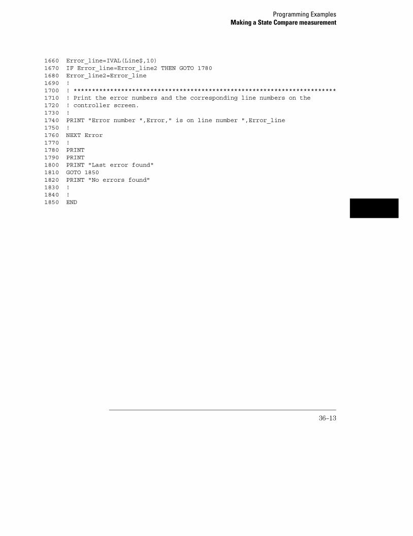
1660 Error_line=IVAL(Line$,10)1670 IF Error_line=Error_line2 THEN GOTO 17801680 Error_line2=Error_line1690 !1700 ! ************************************************************************1710 ! Print the error numbers and the corresponding line numbers on the1720 ! controller screen.1730 !1740 PRINT "Error number ",Error," is on line number ",Error_line1750 !1760 NEXT Error1770 !1780 PRINT 1790 PRINT 1800 PRINT "Last error found"1810 GOTO 18501820 PRINT "No errors found"1830 !1840 !1850 END
Programming ExamplesMaking a State Compare measurement
36–13

Transferring the logic analyzer configuration
This program uses the SYSTem:SETup query to transfer the configurationof the logic analyzer to your controller. This program also uses theSYSTem:SETup command to transfer a logic analyzer configuration from thecontroller back to the logic analyzer. The configuration data will set up thelogic analyzer according to the data. It is useful for getting configurations forsetting up the logic analyzer by the controller. This query differs from theSYSTem:DATA query because it only transfers the configuration and not theacquired data. The SYSTem:SETup command differs from theSYSTem:DATA command because it only transfers the configuration and notacquired data.
10 ! ****************** SETUP COMMAND AND QUERY EXAMPLE ********************20 ! for the 1660-series logic analyzers30 !*** ! ********************* CREATE TRANSFER BUFFER *************************50 ! Create a buffer large enough for the block data. See page 26-9 for55 ! maximum block length.56 !60 ASSIGN @Buff TO BUFFER [170000]70 !80 ! **************** INITIALIZE GPIB DEFAULT ADDRESS *********************90 !100 REAL Address110 Address=707120 ASSIGN @Comm TO Address130 !140 CLEAR SCREEN150 !160 ! ************* INTITIALIZE VARIABLE FOR NUMBER OF BYTES *****************170 ! The variable "Numbytes" contains the number of bytes in the buffer.180 !190 REAL Numbytes200 Numbytes=0210 !220 ! ************** RE-INITIALIZE TRANSFER BUFFER POINTERS ******************230 !240 CONTROL @Buff,3;1250 CONTROL @Buff,4;0260 !270 ! *********************** SEND THE SETUP QUERY **************************
Programming ExamplesTransferring the logic analyzer configuration
36–14
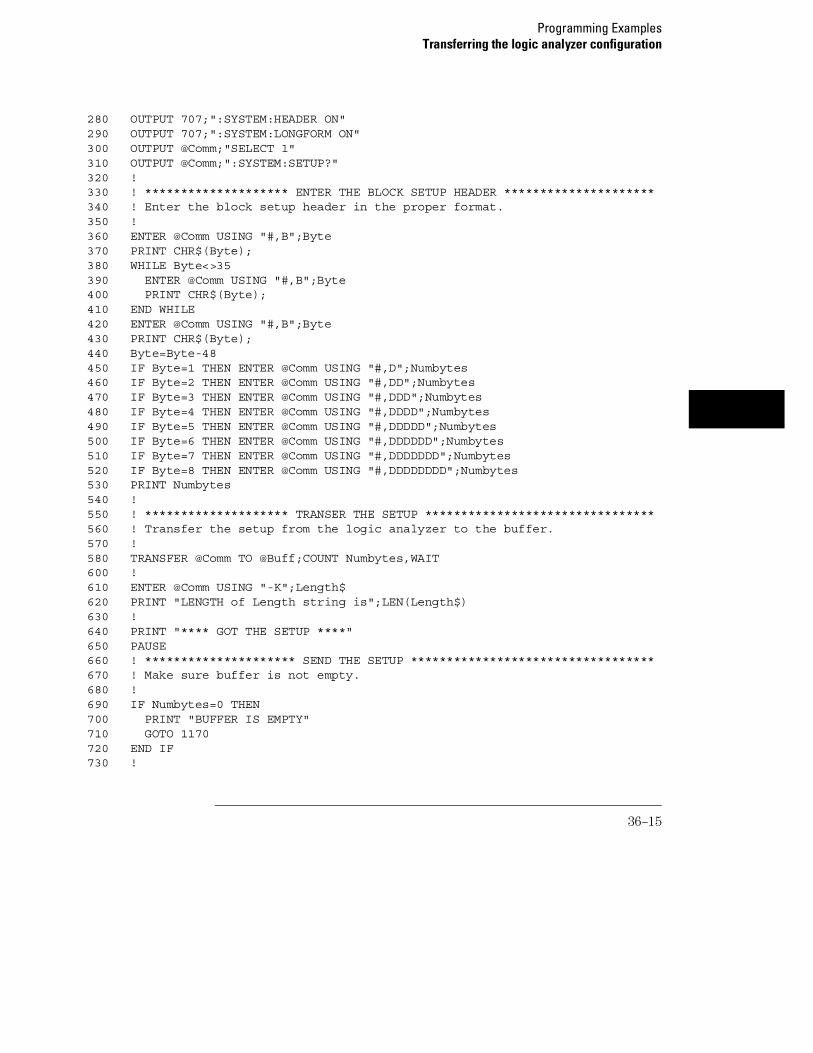
280 OUTPUT 707;":SYSTEM:HEADER ON"290 OUTPUT 707;":SYSTEM:LONGFORM ON"300 OUTPUT @Comm;"SELECT 1"310 OUTPUT @Comm;":SYSTEM:SETUP?"320 !330 ! ******************** ENTER THE BLOCK SETUP HEADER *********************340 ! Enter the block setup header in the proper format.350 !360 ENTER @Comm USING "#,B";Byte370 PRINT CHR$(Byte);380 WHILE Byte<>35390 ENTER @Comm USING "#,B";Byte400 PRINT CHR$(Byte);410 END WHILE420 ENTER @Comm USING "#,B";Byte430 PRINT CHR$(Byte);440 Byte=Byte-48450 IF Byte=1 THEN ENTER @Comm USING "#,D";Numbytes460 IF Byte=2 THEN ENTER @Comm USING "#,DD";Numbytes470 IF Byte=3 THEN ENTER @Comm USING "#,DDD";Numbytes480 IF Byte=4 THEN ENTER @Comm USING "#,DDDD";Numbytes490 IF Byte=5 THEN ENTER @Comm USING "#,DDDDD";Numbytes500 IF Byte=6 THEN ENTER @Comm USING "#,DDDDDD";Numbytes510 IF Byte=7 THEN ENTER @Comm USING "#,DDDDDDD";Numbytes520 IF Byte=8 THEN ENTER @Comm USING "#,DDDDDDDD";Numbytes530 PRINT Numbytes540 !550 ! ******************** TRANSER THE SETUP ********************************560 ! Transfer the setup from the logic analyzer to the buffer.570 !580 TRANSFER @Comm TO @Buff;COUNT Numbytes,WAIT600 !610 ENTER @Comm USING "-K";Length$620 PRINT "LENGTH of Length string is";LEN(Length$)630 !640 PRINT "**** GOT THE SETUP ****"650 PAUSE660 ! ********************* SEND THE SETUP **********************************670 ! Make sure buffer is not empty.680 !690 IF Numbytes=0 THEN 700 PRINT "BUFFER IS EMPTY"710 GOTO 1170720 END IF730 !
Programming ExamplesTransferring the logic analyzer configuration
36–15

740 ! ********************* SEND THE SETUP COMMAND **************************750 ! Send the Setup command760 !770 OUTPUT @Comm USING "#,15A";":SYSTEM:SETUP #"780 PRINT "SYSTEM:SETUP command has been sent"790 PAUSE800 !810 ! ********************* SEND THE BLOCK SETUP ****************************820 ! Send the block setup header to the logic analyzer in the proper format.830 !840 Byte=LEN(VAL$(Numbytes))850 OUTPUT @Comm USING "#,B";(Byte+48)860 IF Byte=1 THEN OUTPUT @Comm USING "#,A";VAL$(Numbytes)870 IF Byte=2 THEN OUTPUT @Comm USING "#,AA";VAL$(Numbytes)880 IF Byte=3 THEN OUTPUT @Comm USING "#,AAA";VAL$(Numbytes)890 IF Byte=4 THEN OUTPUT @Comm USING "#,AAAA";VAL$(Numbytes)900 IF Byte=5 THEN OUTPUT @Comm USING "#,AAAAA";VAL$(Numbytes)910 IF Byte=6 THEN OUTPUT @Comm USING "#,AAAAAA";VAL$(Numbytes)920 IF Byte=7 THEN OUTPUT @Comm USING "#,AAAAAAA";VAL$(Numbytes)930 IF Byte=8 THEN OUTPUT @Comm USING "#,AAAAAAAA";VAL$(Numbytes)940 !950 ! *********************** SAVE BUFFER POINTERS *************************960 ! Save the transfer buffer pointer so it can be restored after the970 ! transfer.980 !990 STATUS @Buff,5;Streg1000 !1010 ! ****************** TRANSFER SETUP TO THE 16550 *********************1020 ! Transfer the setup from the buffer to the 1660A.1030 !1040 TRANSFER @Buff TO @Comm;COUNT Numbytes,WAIT1050 !1060 ! ********************** RESTORE BUFFER POINTERS ***********************1070 ! Restore the transfer buffer pointer1080 !1090 CONTROL @Buff,5;Streg1100 !1110 ! ******************** SEND TERMINATING LINE FEED **********************1120 ! Send the terminating linefeed to properly terminate the setup string.1130 !1140 OUTPUT @Comm;""1150 !1160 PRINT "**** SENT THE SETUP ****"1170 END
Programming ExamplesTransferring the logic analyzer configuration
36–16

Transferring the logic analyzer acquired data
This program uses the SYSTem:DATA query to transfer acquired data toyour controller. It is useful for getting acquired data for setting up the logicanalyzer by the controller at a later time. This query differs from theSYSTem:SETup query because it transfers only the acquired data.
This program also uses the SYSTem:DATA command to transfer the logicanalyzer data from the controller back to the logic analyzer and load theanalyzer with the acquired data. The SYSTem:DATA command differs fromthe SYSTem:SETup command because it transfers both the configurationand the acquired data.
You should always precede the SYSTem:DATA query and command with theSYSTem:SETup query and command if the acquired data depends on a specificconfiguration. If you are only interested in the acquired data for postprocessing in the controller and the data is not dependent on the configuration,you can use the SYSTem:DATA query and command alone.
10 ! ****************** DATA COMMAND AND QUERY EXAMPLE ********************20 ! for the 1660-series logic analyzers30 !40 ! ********************* CREATE TRANSFER BUFFER *************************50 ! Create a buffer large enough for the block data. See page 26-1 for55 ! maximum block length.56 !60 ASSIGN @Buff TO BUFFER [170000]70 !80 ! **************** INITIALIZE GPIB DEFAULT ADDRESS *********************90 !100 REAL Address110 Address=707120 ASSIGN @Comm TO Address130 !140 CLEAR SCREEN150 !160 ! ************* INTITIALIZE VARIABLE FOR NUMBER OF BYTES *****************170 ! The variable "Numbytes" contains the number of bytes in the buffer.180 !190 REAL Numbytes
Programming ExamplesTransferring the logic analyzer acquired data
36–17

200 Numbytes=0210 !220 ! ************** RE-INITIALIZE TRANSFER BUFFER POINTERS ******************230 !240 CONTROL @Buff,3;1250 CONTROL @Buff,4;0260 !270 ! *********************** SEND THE DATA QUERY **************************280 OUTPUT 707;":SYSTEM:HEADER ON"290 OUTPUT 707;":SYSTEM:LONGFORM ON"300 OUTPUT @Comm;"SELECT 1"310 OUTPUT @Comm;":SYSTEM:DATA?"320 !330 ! ******************** ENTER THE BLOCK DATA HEADER *********************340 ! Enter the block data header in the proper format.350 !360 ENTER @Comm USING "#,B";Byte370 PRINT CHR$(Byte);380 WHILE Byte<>35390 ENTER @Comm USING "#,B";Byte400 PRINT CHR$(Byte);410 END WHILE420 ENTER @Comm USING "#,B";Byte430 PRINT CHR$(Byte);440 Byte=Byte-48450 IF Byte=1 THEN ENTER @Comm USING "#,D";Numbytes460 IF Byte=2 THEN ENTER @Comm USING "#,DD";Numbytes470 IF Byte=3 THEN ENTER @Comm USING "#,DDD";Numbytes480 IF Byte=4 THEN ENTER @Comm USING "#,DDDD";Numbytes490 IF Byte=5 THEN ENTER @Comm USING "#,DDDDD";Numbytes500 IF Byte=6 THEN ENTER @Comm USING "#,DDDDDD";Numbytes510 IF Byte=7 THEN ENTER @Comm USING "#,DDDDDDD";Numbytes520 IF Byte=8 THEN ENTER @Comm USING "#,DDDDDDDD";Numbytes530 PRINT Numbytes540 !550 ! ******************** TRANSER THE DATA ********************************560 ! Transfer the data from the logic analyzer to the buffer.570 !580 TRANSFER @Comm TO @Buff;COUNT Numbytes,WAIT600 !610 ENTER @Comm USING "-K";Length$620 PRINT "LENGTH of Length string is";LEN(Length$)630 !640 PRINT "**** GOT THE DATA ****"650 PAUSE
Programming ExamplesTransferring the logic analyzer acquired data
36–18

660 ! ********************* SEND THE DATA **********************************670 ! Make sure buffer is not empty.680 !690 IF Numbytes=0 THEN 700 PRINT "BUFFER IS EMPTY"710 GOTO 1170720 END IF730 !740 ! ********************* SEND THE DATA COMMAND **************************750 ! Send the Setup command760 !770 OUTPUT @Comm USING "#,14A";":SYSTEM:DATA #"780 PRINT "SYSTEM:DATA command has been sent"790 PAUSE800 !810 ! ********************* SEND THE BLOCK DATA ****************************820 ! Send the block data header to the logic analyzer in the proper format.830 !840 Byte=LEN(VAL$(Numbytes))850 OUTPUT @Comm USING "#,B";(Byte+48)860 IF Byte=1 THEN OUTPUT @Comm USING "#,A";VAL$(Numbytes)870 IF Byte=2 THEN OUTPUT @Comm USING "#,AA";VAL$(Numbytes)880 IF Byte=3 THEN OUTPUT @Comm USING "#,AAA";VAL$(Numbytes)890 IF Byte=4 THEN OUTPUT @Comm USING "#,AAAA";VAL$(Numbytes)900 IF Byte=5 THEN OUTPUT @Comm USING "#,AAAAA";VAL$(Numbytes)910 IF Byte=6 THEN OUTPUT @Comm USING "#,AAAAAA";VAL$(Numbytes)920 IF Byte=7 THEN OUTPUT @Comm USING "#,AAAAAAA";VAL$(Numbytes)930 IF Byte=8 THEN OUTPUT @Comm USING "#,AAAAAAAA";VAL$(Numbytes)940 !950 ! *********************** SAVE BUFFER POINTERS *************************960 ! Save the transfer buffer pointer so it can be restored after the970 ! transfer.980 !990 STATUS @Buff,5;Streg1000 !1010 ! ************** TRANSFER DATA TO THE LOGIC ANALYZER *****************1020 ! Transfer the data from the buffer to the logic analyzer.1030 !1040 TRANSFER @Buff TO @Comm;COUNT Numbytes,WAIT1050 !1060 ! ********************** RESTORE BUFFER POINTERS ***********************1070 ! Restore the transfer buffer pointer1080 !1090 CONTROL @Buff,5;Streg1100 !
Programming ExamplesTransferring the logic analyzer acquired data
36–19

1110 ! ******************** SEND TERMINATING LINE FEED **********************1120 ! Send the terminating linefeed to properly terminate the data string.1130 !1140 OUTPUT @Comm;""1150 !1160 PRINT "**** SENT THE DATA ****"1170 END
Programming ExamplesTransferring the logic analyzer acquired data
36–20

Checking for measurement completion
This program can be appended to or inserted into another program when youneed to know when a measurement is complete. If it is at the end of aprogram it will tell you when measurement is complete. If you insert it into aprogram, it will halt the program until the current measurement is complete.
This program is also in the state analyzer example program in "Making a StateAnalyzer Measurement" on pages 27-7 and 27-8. It is included in the stateanalyzer example program to show how it can be used in a program to haltthe program until measurement is complete.
420 ! ****************** CHECK FOR MEASUREMENT COMPLETE **********************430 ! Enable the MESR register and query the register for a measurement440 ! complete condition.450 !460 OUTPUT 707;":SYSTEM:HEADER OFF"470 OUTPUT 707;":SYSTEM:LONGFORM OFF"480 !490 Status=0500 OUTPUT 707;":MESE1 1"510 OUTPUT 707;":MESR1?"520 ENTER 707;Status530 !540 ! Print the MESR register status.550 !560 CLEAR SCREEN570 PRINT "Measurement complete status is ";Status580 PRINT "0 = not complete, 1 = complete"590 ! Repeat the MESR query until measurement is complete.600 WAIT 1610 IF Status=1 THEN GOTO 630620 GOTO 510630 PRINT TABXY(30,15);"Measurement is complete"640 !650 END
Programming ExamplesChecking for measurement completion
36–21

Sending queries to the logic analyzer
This program example contains the steps required to send a query to thelogic analyzer. Sending the query alone only puts the requested informationin an output buffer of the logic analyzer. You must follow the query with anENTER statement to transfer the query response to the controller. When thequery response is sent to the logic analyzer, the query is properly terminatedin the logic analyer. If you send the query but fail to send an ENTERstatement, the logic analyzer will display the error message "QueryInterrupted" when it receives the next command from the controller, and, thequery response is lost.
10 !************************ QUERY EXAMPLE ***********************20 ! for the 1660-series Logic Analyzers30 !40 ! ************************ OPTIONAL ***************************50 ! The following two lines turn the headers and longform on so60 ! that the query name, in its long form, is included in the70 ! query response.80 !90 ! ************** NOTE ****************100 ! If your query response includes real110 ! or integer numbers that you may want120 ! to do statistics or math on later, you130 ! should turn both header and longform140 ! off so only the number is returned.150 ! *************************************160 !170 OUTPUT 707;":SYSTEM:HEADER ON"180 OUTPUT 707;":SYSTEM:LONGFORM ON"190 !200 ! *************************************************************210 ! Select the slot in which the logic analyzer is located.220 ! Always a 1 for the 1660-series logic analyzers.230 OUTPUT 707;":SELECT 1"240 !250 ! ****************************************************************260 ! Dimension a string in which the query response will be entered.270 !280 DIM Query$[100]290 !300 ! ****************************************************************
Programming ExamplesSending queries to the logic analyzer
36–22

310 ! Send the query. In this example the MENU? query is sent. All320 ! queries except the SYSTem:DATA and SYSTem:SETup can be sent with330 ! this program.340 !350 OUTPUT 707;"MENU?"360 !370 ! ****************************************************************380 ! The two lines that follow transfer the query response from the390 ! query buffer to the controller and then print the response.400 !410 ENTER 707;Query$420 PRINT Query$430 !440 !450 END
Programming ExamplesSending queries to the logic analyzer
36–23

Getting ASCII Data with PRINt? ALL Query
This program example shows you how to get ASCII data from a state listingusing the PRINt? ALL query. There are two things you must keep in mind:
• You must select the logic analyzer, which is always SELECT 1 for the1660-series logic analyzers.
• You must select the proper menu. The only menus that allow you to usethe PRINt? ALL query are the listing menus and the disk menu.
10 ! ****** ASCII DATA *******20 !30 !40 ! This program gets STATE Listing data from the 1660-series logic50 ! analyzers in ASCII form by using the PRINT? ALL query.60 !70 !****************************************************************80 !90 DIM Block$[32000]100 OUTPUT 707;"EOI ON"110 OUTPUT 707;":SYSTEM:HEAD OFF"120 OUTPUT 707;":SELECT 1" ! Always a 1 for the 1660-series logic130 ! analyzers.140 !150 OUTPUT 707;":MENU 1,7" ! Selects the Listing 1 menu. Print? All160 ! will only work in Listing and Disk menus.170 !180 OUTPUT 707;":SYSTEM:PRINT? ALL"190 ENTER 707 USING "-K";Block$200 !210 !****************************************************************220 ! Now display the ASCII data you received.230 !240 PRINT USING "K";Block$250 !260 END
Programming ExamplesGetting ASCII Data with PRINt? ALL Query
36–24
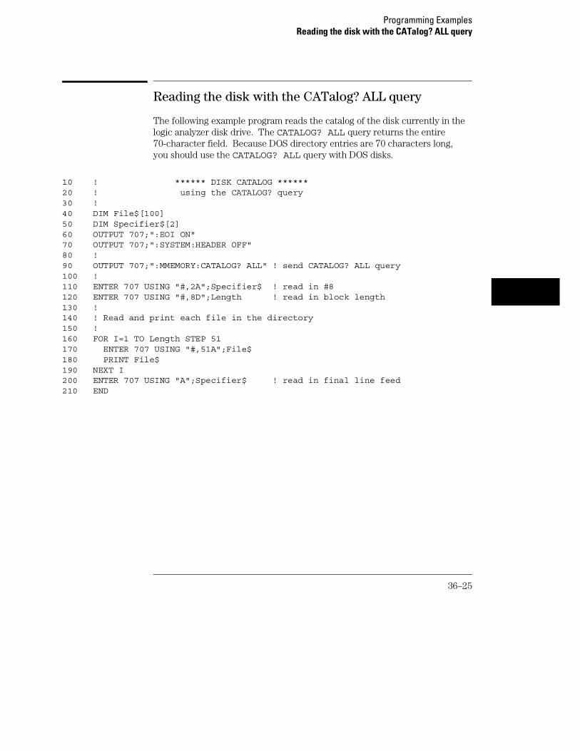
Reading the disk with the CATalog? ALL query
The following example program reads the catalog of the disk currently in thelogic analyzer disk drive. The CATALOG? ALL query returns the entire70-character field. Because DOS directory entries are 70 characters long,you should use the CATALOG? ALL query with DOS disks.
10 ! ****** DISK CATALOG ******20 ! using the CATALOG? query30 !40 DIM File$[100]50 DIM Specifier$[2]60 OUTPUT 707;":EOI ON"70 OUTPUT 707;":SYSTEM:HEADER OFF"80 !90 OUTPUT 707;":MMEMORY:CATALOG? ALL" ! send CATALOG? ALL query100 !110 ENTER 707 USING "#,2A";Specifier$ ! read in #8120 ENTER 707 USING "#,8D";Length ! read in block length130 !140 ! Read and print each file in the directory150 !160 FOR I=1 TO Length STEP 51170 ENTER 707 USING "#,51A";File$180 PRINT File$190 NEXT I200 ENTER 707 USING "A";Specifier$ ! read in final line feed210 END
Programming ExamplesReading the disk with the CATalog? ALL query
36–25

Reading the Disk with the CATalog? Query
This example program uses the CATALOG? query without the ALL optionto read the catalog of the disk currently in the logic analyzer disk drive.However, if you do not use the ALL option, the query only returns a51-character field. Keep in mind if you use this program with a DOS disk,each filename entry will be truncated at 51 characters.
10 ! ****** DISK CATALOG ******20 ! using the CATALOG? query30 !40 DIM File$[100]50 DIM Specifier$[2]60 OUTPUT 707;":EOI ON"70 OUTPUT 707;":SYSTEM:HEADER OFF"80 !90 OUTPUT 707;":MMEMORY:CATALOG?" ! send CATALOG? query100 !110 ENTER 707 USING "#,2A";Specifier$ ! read in #8120 ENTER 707 USING "#,8D";Length ! read in block length130 !140 ! Read and print each file in the directory150 !160 FOR I=1 TO Length STEP 51170 ENTER 707 USING "#,51A";File$180 PRINT File$190 NEXT I200 ENTER 707 USING "A";Specifier$ ! read in final line feed210 END
Programming ExamplesReading the Disk with the CATalog? Query
36–26

Printing to the disk
This program prints acquired data to a disk file. The file can be either on aLIF or DOS disk. If you print the file to a DOS disk, you will be able to viewthe file on a DOS compatible computer using any number of file utilityprograms.
10 ! ********* PRINTING TO A DISK FILE **********20 !30 !40 ! This program prints the acquired data to a disk file. I will50 ! print to either a LIF or DOS file using the PRINT ALL command.60 !70 !****************************************************************80 !90 OUTPUT 707;":SELECT 1" ! Always a 1 for the 1660-series logic100 ! analyzers.110 !120 OUTPUT 707;":MENU 1,7" ! Selects the Listing 1 menu. Print to disk130 ! will only work in Listing and Disk menus.140 !150 OUTPUT 707;":SYSTEM:PRINT ALL, DISK, ’DISKFILE’"160 !170 !****************************************************************180 ! Now display catalog to see that the file has been saved on the disk.190 !200 DIM File$[100]210 DIM Specifier$[2]220 OUTPUT 707;":EOI ON"230 OUTPUT 707;":SYSTEM:HEADER OFF"240 OUTPUT 707;":MMEMORY:CATALOG? ALL"250 ENTER 707 USING "#,2A";Specifier$260 ENTER 707 USING "#,8D";Length270 FOR I=1 TO Length STEP 70280 ENTER 707 USING "#,70A";File$290 PRINT File$300 NEXT I310 ENTER 707 USING "A";Specifier$320 END
Programming ExamplesPrinting to the disk
36–27

Transferring waveform data in Byte format
This program sets up the oscilloscope module to move oscilloscope waveformdata from the 1660-series to a controller in Byte format.
10 ! Transferring Waveform Data20 ! Byte Format30 !40 CLEAR 70750 !*************** Select the oscilloscope ******I****************60 !70 OUTPUT 707;":SELECT 2"80 !90 !*************** Set EOI on and Headers Off ********************100 OUTPUT 707;":EOI ON"110 OUTPUT 707;":SYSTEM:HEADER OFF"120 !130 !*************** Set up the Oscilloscope ***********************140 !150 OUTPUT 707;":ACQUIRE:TYPE NORMAL"160 OUTPUT 707;":WAVEFORM:SOURCE CHANNELS"170 OUTPUT 707 WAVEFORM:FORMAT BYTE"180 OUTPUT 707;":WAVEFORM:RECORD FULL"190 !200 !*************** Start Waveform Acquisition ********************210 OUTPUT 707;":AUTOSCALE"220 !230 ! *************** Dimension a string for the data ***************240 !250 DIM Header$[20]260 !270 ! *************** Digitize the data and display Waveform menu ***280 !290 OUTPUT 707; ":DIGITIZE"300 OUTPUT 707; ":MENU 2,3"310 WAIT 5320 Length=8000330 ALLOCATE INTEGER Waveform(1:Length)340 !350 !*************** Transfer the waveform data ********************360 !370 OUTPUT 707;":WAVEFORM:DATA?"380 ENTER 707 USING "#,l0A";Header$
Programming ExamplesTransferring waveform data in Byte format
36–28

390 ENTER 707 USING "#,B";Waveform(*)400 ENTER 707 USING "#,B";Lastchar410 !420 !*************** Print the waveform data ***********************430 PRINT "Header = ";Header$440 PRINT450 PRINT "Press CONTINUE to display waveform data"460 PRINT470 PRINT Waveform(*)490 PRINT500 PRINT Lastchar510 END
Programming ExamplesTransferring waveform data in Byte format
36–29

Transferring waveform data in Word format
This program sets up the oscilloscope module to move oscilloscope waveformdata from the 1660-series to a controller in Word format.
10 ! Transferring Waveform Data20 ! Word Format30 !40 CLEAR 70750 !*************** Select the Oscilloscope ***********************60 !70 OUTPUT 707;":SELECT 2"80 !90 !*************** Set EOI on and Headers Off ********************100 OUTPUT 707;":EOI ON"110 OUTPUT 707;":SYSTEM:HEADER OFF"120 !130 !*************** Set up the Oscilloscope ***********************140 !150 OUTPUT 707;":ACQUIRE:TYPE AVERAGE"160 OUTPUT 707;":WAVEFORM:SOURCE CHANNEL 1"170 OUTPUT 707,":WAVEFORM:FORMAT WORD"180 OUTPUT 707;":WAVEFORM:RECORD FULL"190 !200 !*************** Start Waveform Acquisition ********************210 OUTPUT 707;":AUTOSCALE"220 !230 !*************** Dimension a string for the data ***************240 !250 DIM Header$[20]260 !270 !*************** Digitize the data and display Waveform menu ***280 !290 OUTPUT 707;":DIGITIZE"300 OUTPUT 707;":MENU 2,3"310 WAIT 5320 Length=8000330 ALLOCATE INTEGER Waveform(1:Length)340 !350 !*************** Transfer the waveform data ********************360 !370 OUTPUT 707;":WAVEFORM:DATA?"380 ENTER 707 USING "#,10A";Header$
Programming ExamplesTransferring waveform data in Word format
36–30

390 ENTER 707 USING "#,B";Waveform(*)400 ENTER 707 USING "#,B";Lastchar410 !420 ! *************** Print the waveform data ***********************430 PRINT "Header = ";Header$440 PRINT450 PRINT "Press CONTINUE to display waveform data"460 PRINT470 PAUSE480 PRINT Waveform(*)490 PRINT500 PRINT Lastchar510 END
Programming ExamplesTransferring waveform data in Word format
36–31

Using AUToscale and the MEASure:ALL? Query
This very simple program example shows how to use Autoscale to acquire awaveform and the MEASure:ALL? query to read in the measurement results.
10 OUTPUT 707; ":SYSTEM:HEADER ON"20 OUTPUT 707; ":EOI ON"30 OUTPUT 707; ":SELECT 2"40 OUTPUT 707; ":AUTOSCALE"50 WAIT 560 DIM Me$[200]70 OUTPUT 707; ":MEASURE:SOURCE CHANNEL 1;ALL?"80 ENTER 707 USING "#,200A";Me$90 PRINT USING "#,200A";Me$100 END
Programming ExamplesUsing AUToscale and the MEASure:ALL? Query
36–32

Using Sub-routines in a measurement program
This program example shows a measurement example using sub-routines inHP BASIC. The tasks perfumed in this example are:
• Initializing the interface and the oscilloscope
• Digitizing the acquired signal data
• Measuring and printing the frequency and peak-to-peak voltage of theacquired signal.
10 ! Measurement Example Using Sub-routines20 !30 !MAIN PROGRAM40 !50 CLEAR SCREEN60 PRINT "This example program will perform the following tasks:"70 PRINT " a. initialize the interface and oscilloscope"80 PRINT " b. digitize the signal "90 PRINT " c. measure and print the frequency "100 PRINT110 PRINT "The program assumes the system is configured as:"120 PRINT " GPIB address = 7"130 PRINT " Oscilloscope address = 7"140 PRINT " Oscilloscope card is in slot 2"150 PRINT " Signal attached to channel 1"160 PRINT170 PRINT "If the addresses are not correct for your configuration, change"180 PRINT "the ASSIGN statements in the Initialize function."190 PRINT200 PRINT "Press Continue when ready to start program, or Shift/Break toterminate."210 PAUSE220 GOSUB Initialize !initialize interface and oscilloscope230 GOSUB Get_waveform !digitize signal240 GOSUB Measure !measure and print frequency250 STOP260 !270 !INITIALIZE INTERFACE AND OSCILLOSCOPE280 !290 Initialize:300 ASSIGN @Scope TO 707 !System address310 ASSIGN @Isc TO 7 !GPIB address
Programming ExamplesUsing Sub-routines in a measurement program
36–33
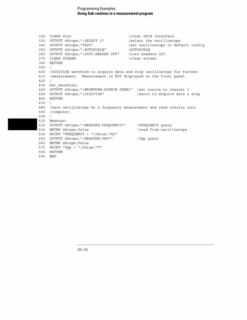
320 CLEAR @Isc !clear GPIB interface330 OUTPUT @Scope;":SELECT 2" !select the oscilloscope340 OUTPUT @Scope;"*RST" !set oscilloscope to default config350 OUTPUT @Scope;":AUTOSCALE" !AUTOSCALE360 OUTPUT @Scope;":SYST:HEADER OFF" !turn headers off370 CLEAR SCREEN !clear screen380 RETURN390 !400 !DIGITIZE waveform to acquire data and stop oscilloscope for further410 !measurement. Measurement is NOT displayed on the front panel.420 !430 Get_waveform:440 OUTPUT @Scope;":WAVEFORM:SOURCE CHAN1" !set source to channel 1450 OUTPUT @Scope;":DIGITIZE" !macro to acquire data & stop460 RETURN470 !480 !have oscilloscope do a frequency measurement and read results into490 !computer.500 !510 Measure:520 OUTPUT @Scope;":MEASURE:FREQUENCY?" !FREQUENCY query530 ENTER @Scope;Value !read from oscilloscope540 PRINT "FREQUENCY = ";Value;"Hz"550 OUTPUT @Scope;":MEASURE:VPP?" !Vpp query560 ENTER @Scope;Value570 PRINT "Vpp = ";Value;"V"580 RETURN590 END
Programming ExamplesUsing Sub-routines in a measurement program
36–34

Index
!
*CLS command, 8–5*ESE command, 8–6*ESR command, 8–7*IDN command, 8–9*IST command, 8–9*OPC command, 8–11*OPT command, 8–12*PRE command, 8–13*RST command, 8–14*SRE command, 8–15*STB command, 8–16*TRG command, 8–17*TST command, 8–18*WAI command, 8–19..., 4–532767, 4–49.9E+37, 4–4::=, 4–5 , 4–5[ ], 4–5{ }, 4–5|, 4–5
A
ABVolt?, 31–7ACCumulate, 28–3, 30–4, 30–7ACCumulate command/query, 18–5, 19–4,23–7ACCumulate?, 30–4ACQMode command/query, 21–5ACQuire Subsystem, 28–2acquire waveform data, 27–5acquired data, 35–14ACQuisition command/query, 16–9, 18–5,22–9, 23–8acquisition type, 28–3, 35–2, 35–13
Average, 28–3Normal, 28–3
ACSII format, 35–5adding waveforms, 30–9Addressed talk/listen mode, 2–3ALL, 32–5ALL?, 32–5Analyzer 1 Data Information, 26–7Analyzer 2 Data Information, 26–9Angular brackets, 4–5Arguments, 1–7ARM command/query, 13–5
ASCII Format, 35–5ASCII transfer, 35–4ASSign command/query, 13–5attenuation factor, 29–7auto timebase mode, 33–5AUToload command, 11–8AUToscale, 27–3Average mode, 28–3, 35–3averaging data points, 28–3AVOLt, 31–6AVOLt?, 31–6
B
BASE command, 25–5base voltage measurement, 32–11Bases, 1–12Basic, 1–3Baud rate, 3–9BEEPer command, 9–6Bit definitions, 6–4, 6–5bit_id, 30–4Block data, 1–6, 1–20, 26–4Block length specifier, 26–4Block length specifier, 10–5, 10–11Block length specifier>, 26–16Block length specifier>>, 26–4Braces, 4–5BRANch command/query, 16–10, 16–11,22–9, 22–10, 22–11BVOLt, 31–7BVOLt?, 31–8byte data structure, 35–4BYTE format, 35–4byte transfer, 35–4
C
CableRS-232C, 3–3
CAPability command, 9–7CARDcage?, 9–8CATalog command, 11–9CENTer, 31–8CENTer command, 18–6, 23–8center screen voltage, 29–6CESE command, 9–9CESR command, 9–10channel display, 29–2CHANnel Subsystem, 29–2channel_number, 29–4, 30–4, 31–5, 32–4,
34–4, 35–8chart display, 19–2CLEar command, 16–12, 20–5, 22–12Clear To Send (CTS), 3–5clearing the display, 30–9CLOCk command/query, 15–6CLRPattern command, 17–8, 18–6, 23–9,24–8CLRStat command, 18–7, 23–9CMASk command/query, 20–5CME, 6–5COLumn command/query, 17–7, 24–7Combining commands, 1–9Comma, 1–12Command, 1–6, 1–16
*CLS, 8–5*ESE, 8–6*OPC, 8–11*PRE, 8–13*RST, 8–14*SRE, 8–15*TRG, 8–17*WAI, 8–19ACCumulate, 18–5, 19–4, 23–7, 30–4, 30–7ACQMode, 21–5ACQuisition, 16–9, 22–9ARM, 13–5ASSign, 13–5AUToload, 11–8BASE, 25–5BEEPer, 9–6BRANch, 16–10, 22–9CENTer, 18–6, 23–8CESE, 9–9CLEar, 20–5CLOCk, 15–6CLRPattern, 17–8, 18–6, 23–9, 24–8CLRStat, 18–7, 23–9CMASk, 20–5COLumn, 17–7, 24–7COMPare, 20–4CONDition, 34–5CONNect, 30–5COPY, 11–10, 20–6COUNt, 28–4DATA, 10–5, 20–7, 26–4DELay, 14–5, 18–7, 23–9, 33–4, 34–7DELete, 12–5DOWNload, 11–11
Index–1

DSP, 10–6EOI, 9–11FIND, 16–13, 22–13FORMat, 35–10GLEDge, 22–14HAXis, 19–5HEADer, 1–16, 10–8INITialize, 11–13INPort, 12–6INSert, 12–7, 14–6, 18–8, 23–10, 30–5LABel, 15–7, 21–6LEVel, 34–8LEVelarm, 13–6LINE, 14–7, 17–9, 20–10, 24–9LOAD:CONFig, 11–14LOAD:IASSembler, 11–15LOCKout, 3–11, 9–12LOGic, 34–10LONGform, 1–16, 10–9Machine, 13–4MASTer, 15–9MENU, 9–12, 20–10MESE, 9–14MINus, 30–8MMODe, 17–10, 23–11, 24–10, 31–8,
31–12, 31–14, 31–15MODE, 33–5, 34–11MSI, 11–16MSTats, 31–8NAME, 13–7OAUTo, 31–9OCONdition, 23–12, 24–11OFFSet, 29–6OPATtern, 17–11, 23–13, 24–11OSEarch, 17–12, 23–14, 24–12OTAG, 17–13, 24–14OTIMe, 14–8, 23–15, 31–6, 31–7, 31–10OVERlay, 17–14, 30–8PACK, 11–17PATH, 34–12PATTern, 25–6PLUS, 30–9PRINt, 10–10PROBe, 29–7PURGe, 11–17RANGe, 14–9, 16–14, 18–8, 20–11, 22–15,
23–16, 25–6, 29–8, 33–6RECord, 35–12
REMove, 14–10, 15–13, 17–15, 18–9, 21–7,23–16, 24–14, 25–7, 30–9
REName, 11–18, 13–8RESource, 13–9RMODe, 9–18RUNTil, 17–15, 20–12, 23–17, 24–15, 31–11SCHart, 19–4SELect, 9–20SEQuence, 16–16, 22–17SET, 20–13SETColor, 9–22SETup, 10–11, 26–15SFORmat, 15–6SKEW, 12–8SLAVe, 15–15SLISt, 17–7SLOPe, 34–12SOURce, 32–10, 34–13, 35–12SPERiod, 22–18, 23–18STARt, 9–23STOP, 9–24STORe, 16–17STORe:CONFig, 11–19SWAVeform, 18–4SYMBol, 25–4SYStem:DATA, 10–5, 26–2, 26–4SYStem:SETup, 10–11, 26–2, 26–15TAG, 16–18TAKenbranch, 16–19, 18–9TCONtrol, 16–20, 22–19TERM, 16–21, 22–20TFORmat, 21–4THReshold, 15–18, 21–8TIMER, 16–22, 22–21TLISt, 24–7TPOSition, 16–23, 18–10, 22–22, 23–20TREE, 12–9TTL, 29–9TYPE, 13–10, 28–4VAXis, 19–7WIDTh, 25–8WLISt, 14–4XAUTo, 31–18XCONdition, 23–22, 24–18XPATtern, 17–20, 23–23, 24–19XSEarch, 17–21, 23–24, 24–20XTAG, 17–22, 24–22XTIMe, 14–11, 23–25, 31–19
Command errors, 7–3Command mode, 2–3Command set organization, 4–14Command structure, 1–4Command tree, 4–5
SELect, 9–21Command types, 4–6Commands
ACCumulate, 30–4AUToscale, 27–3, 27–4AVOLt, 31–6BVOLt, 31–7CENTer, 31–8CONDition, 34–5, 34–6CONNect, 30–5COUNt, 28–4COUPling, 29–4DELay, 33–4, 34–7DIGitize, 27–5ECL, 29–5FORMat, 35–10INSert, 30–5, 30–6LABel, 30–7LEVel, 34–8, 34–9LOGic, 34–10MINus, 30–8MODE, 33–5, 34–11MSTats, 31–8OAUTo, 31–9OFFset, 29–6OTIMe, 31–10OVERlay, 30–8PATH, 34–12PLUS, 30–9PROBe, 29–7RANGe, 29–8, 33–6RECord, 35–12REMove, 30–9, 30–10RUNTil, 31–11SHOW, 31–12SOURce, 34–13, 35–12TMODe, 31–14TTL, 29–9TYPE, 28–4, 28–5VMODe, 31–15XAUTo, 31–18XTIMe, 31–19, 31–20
Common commands, 1–9, 4–6, 8–2
Index
Index–2

Communication, 1–3compare
program example, 36–9COMPare selector, 20–4COMPare Subsystem, 20–1, 20–3, 20–4,20–5, 20–6, 20–7, 20–8, 20–9, 20–10,20–11, 20–12, 20–13Complex qualifier, 16–11, 22–11Compound commands, 1–8CONDition, 34–5, 34–6CONDition?, 34–6Configuration file, 1–4CONNect, 30–5connect dots, 30–5CONNect?, 30–5Controller mode, 2–3Controllers, 1–3Conventions, 4–5COPY command, 11–10, 20–6COUNt, 28–3, 28–4, 35–9COUNt?, 28–4, 35–9count_argument, 28–3
count_number, 34–4COUPling, 29–4COUPling?, 29–5
D
DATA, 10–5, 26–4, 35–9command, 10–5State (no tags, 26–10, 26–11
data acquisition, 28–3Data acquisition type, 35–2Data and Setup Commands, 26–1, 26–3,26–4, 26–5, 26–6, 26–7, 26–8, 26–9, 26–10,26–11, 26–12, 26–13, 26–14, 26–15, 26–16,26–17data averaging, 35–3Data bits, 3–9
8-Bit mode, 3–9Data block
Analyzer 1 data, 26–7Analyzer 2 data, 26–9Data preamble, 26–6Section data, 26–6Section header, 26–6
Data Carrier Detect(DCD), 3–5DATA command/query, 10–5, 20–7, 20–8data conversion, 35–6, 35–7, 35–8
Data mode, 2–3Data preamble, 26–6, 26–7, 26–8, 26–9DATA query, 17–9, 24–9Data Terminal Equipment, 3–3Data Terminal Ready(DTR), 3–5data to time conversion, 35–6data transfer, 35–2, 35–12data transfer format, 35–4, 35–5data transmission mode, 35–10data value to trigger point conversion, 35–6DATA?, 35–9DataCommunications Equipment, 3–3DataSet Ready (DSR), 3–5DCE, 3–3DCL, 2–6DDE, 6–5Definite-length block response data, 1–20DELay, 33–4, 34–7DELay command/query, 14–5, 18–7, 23–9DELay?, 33–4, 34–7delay_argument, 33–3DELete command, 12–5delta voltage measurement, 31–7Device address, 1–6
GPIB, 2–4RS-232C, 3–10
Device clear, 2–6Device dependent errors, 7–3DIGitize, 27–5display of waveforms, 30–5DISPlay Subsystem, 30–2Documentation conventions, 4–5DOWNload command, 11–11DSP command, 10–6DTE, 3–3Duplicate keywords, 1–9
E
ECL, 29–5edge search, 31–16EDGE trigger, 34–2, 34–11EDGE Trigger Mode, 34–2Ellipsis, 4–5Embedded strings, 1–3, 1–6Enter statement, 1–3EOI command, 9–11ERRor command, 10–7Error messages, 7–2
ESB, 6–4Event Status Register, 6–4Example
Using AUToscale, 27–4Examples
program, 36–2EXE, 6–5Execution errors, 7–4Exponents, 1–12Extended interface, 3–4
F
FALLtime, 32–6falltime measurement, 32–6FALLtime?, 32–6File types, 11–12FIND command/query, 16–13, 22–13FIND query, 20–9FORMat, 35–10FORMat?, 35–10Fractional values, 1–13FREQuency, 32–6frequency measurement, 32–6FREQuency?, 32–6
G
GET, 2–6GLEDge command/query, 22–14GPIB, 2–2, 2–3, 6–8GPIB address, 2–3GPIB device address, 2–4GPIB interface, 2–3GPIB interface code, 2–4GPIB interface functions, 2–2greater than_argument, 31–5Group execute trigger, 2–6
H
HAXis command/query, 19–5, 19–6HEADer command, 1–16, 10–8Headers, 1–6, 1–8, 1–11horizontal time range, 33–6Host language, 1–6HTIMe query, 12–6
I
Index
Index–3

Identification number, 9–8Identifying modules, 9–8IEEE 488.1, 2–2, 5–2IEEE 488.1 bus commands, 2–6IEEE 488.2, 5–2IFC, 2–6immediate trigger, 34–11infinite persistence, 30–4Infinity, 4–4Initialization, 1–4INITialize command, 11–13INPort command, 12–6Input buffer, 5–3input impedance, 29–5inrange_greater than, 31–5inrange_less than, 31–5INSert, 30–5, 30–6INSert command, 12–7, 14–6, 18–8, 23–10Instruction headers, 1–6Instruction parameters, 1–7Instruction syntax, 1–5Instruction terminator, 1–7Instructions, 1–5Instrument address, 2–4Interface capabilities, 2–3
RS-232C, 3–9Interface clear, 2–6Interface code
GPIB, 2–4Interface selectcode
RS-232C, 3–10INTermodule subsystem, 12–2Internal errors, 7–4
K
Keyword data, 1–13Keywords, 4–3
L
LABel, 30–7LABel command/query, 15–7, 15–8, 21–6label string, 30–7LABel?, 30–7label_id, 30–4label_string, 30–4LCL, 6–6LER command, 9–11less than_argument, 31–5
level, 31–5, 34–8, 34–9LEVel?, 34–9LEVelarm command/query, 13–6LINE command/query, 14–7, 17–9, 20–10,24–9Linefeed, 1–7, 4–5LOAD:CONFig command, 11–14LOAD:IASSembler command, 11–15Local, 2–5Local lockout, 2–5LOCKout command, 3–11, 9–12LOGic, 34–10logic pattern, 34–5LOGic?, 34–10Longform, 1–11LONGform command, 1–16, 10–9Lowercase, 1–11
M
Machine selector, 13–4MACHine Subsystem, 13–1, 13–3, 13–4,13–5, 13–6, 13–7, 13–8, 13–9, 13–10Mainframe commands, 9–2Marker data, 31–12marker placement, 31–18MARKer Subsystem, 31–2, 32–2marker to center, 31–8marker_time, 31–5MASTer command/query, 15–9MAV, 6–4maximum voltage measurement, 32–12measurement complete program example,36–21Measurement parameters
Falltime, 32–2Frequency, 32–2Negative pulse width, 32–2Overshoot, 32–3Peak-to-peak, 32–2Period, 32–2Positive pulse width, 32–2Preshoot, 32–3Risetime, 32–2
measurement source, 32–10measurement statistics, 31–8MENU command, 9–12, 20–10MESE command, 9–14MESR command, 9–16
minimum voltage measurement, 32–12MINus, 30–8MMEMory subsystem, 11–2MMODe, 31–14, 31–15MMODe command/query, 17–10, 23–11,24–10Mnemonics, 1–13, 4–3MODE, 33–5, 34–11MODE?, 33–5, 34–11Module commands, 27–2moving the X marker, 31–19MSB, 6–6MSG, 6–5MSI command, 11–16MSS, 6–4MSTats, 31–8MSTats?, 31–9Msus, 11–3multiple measurements, 32–5Multiple numeric variables, 1–21Multiple program commands, 1–14Multiple queries, 1–21Multiple subsystems, 1–14
N
NAME command/query, 13–7negative width time measurement, 32–7New Line character, 1–7NL, 1–7, 4–5Normal mode, 28–3, 35–2Notation conventions, 4–5number of averages, 28–3Numeric base, 1–19Numeric bases, 1–12Numeric data, 1–12Numeric variables, 1–19NWIDth, 32–7NWIDth?, 32–7
O
O Marker placement, 31–9, 31–10O marker voltage level, 31–16OAUTo, 31–9OAUTo?, 31–10occurrence, 31–5OCONdition command/query, 23–12, 24–11OFFSet, 29–6offset voltage, 29–4, 29–6
Index
Index–4

OFFset?, 29–6offset_argument, 29–4OPATtern command/query, 17–11, 23–13,24–11OPC, 6–5Operation Complete, 6–6OR notation, 4–5OSEarch command/query, 17–12, 23–14,24–12OSTate query, 14–8, 17–13, 24–13OTAG command/query, 17–13, 24–14OTIMe, 31–6, 31–7, 31–10OTIMe command/query, 14–8, 23–15OTIMe?, 31–10Output buffer, 1–10Output queue, 5–3OUTPUT statement, 1–3, 27–4outrange_greater than, 31–5outrange_less than, 31–5Overlapped command, 8–11, 8–19, 9–23,9–24Overlapped commands, 4–4OVERlay, 30–8OVERlay command/query, 17–14overlaying waveforms, 30–8OVERshoot, 32–7overshoot measurement, 32–7OVERshoot?, 32–7OVOLt, 31–16
P
PACK command, 11–17Parameter syntax rules, 1–12Parameters, 1–7Parity, 3–9Parse tree, 5–8Parser, 5–3PATH, 34–12PATH?, 34–12PATTern command, 25–6pattern duration, 34–5PATTern trigger, 34–2, 34–11PATTern Trigger Mode, 34–2peak-to-peak voltage measurement, 32–13PERiod, 32–8period measurement, 32–8PERiod?, 32–8PLUS, 30–9
POINts, 35–10points on screen, 35–10POINts?, 35–10PON, 6–5positive pulse width measurement, 32–9preamble, 35–2, 35–11Preamble description, 26–6PREamble?, 35–11preset user, 29–5, 29–9PREShoot, 32–8preshoot measurement, 32–8PREShoot?, 32–8PRINt command, 10–10Printer mode, 2–3Printing to the disk, 36–27PROBe, 29–7PROBe?, 29–7probe_argument, 29–4program example
checking for measurement complete, 36–21compare, 36–9getting ASCII data with PRINt ALL query,
36–24sending queries to the logic analyzer, 36–22state analyzer, 36–5SYSTem:DATA command, 36–17SYSTem:DATA query, 36–17SYSTem:SETup command, 36–14SYSTem:SETup query, 36–14timing analyzer, 36–3transferring configuration to analyzer,
36–14transferring configuration to the
controller, 36–14transferring setup and data to the
analyzer, 36–17transferring setup and data to the
controller, 36–17transferring waveform data, 36–28, 36–30using AUTOscale and the MEASure:ALL?
Query, 36–32Using Sub-routines, 36–33
Program examples, 4–16, 36–2Program message syntax, 1–5Program message terminator, 1–7Program syntax, 1–5Programming conventions, 4–5Protocol, 3–9, 5–4
None, 3–9XON/XOFF, 3–9
Protocol exceptions, 5–5Protocols, 5–3PURGe command, 11–17PWIDth, 32–9PWIDth?, 32–9
Q
Query, 1–6, 1–10, 1–16*ESE, 8–6*ESR, 8–7*IDN, 8–9*IST, 8–9*OPC, 8–11*OPT, 8–12*PRE, 8–13*SRE, 8–15*STB, 8–16*TST, 8–18ABVolt?, 31–7ACCumulate, 18–5, 19–5, 23–7, 30–4, 30–7ACCumulate?, 30–4ACQMode, 21–5ACQuisition, 16–9, 22–9ALL, 32–5ALL?, 32–5ARM, 13–5ASSign, 13–6AUToload, 11–8AVOLt?, 31–6BEEPer, 9–6BRANch, 16–11, 22–11BVOLt?, 31–8CAPability, 9–7CATalog, 11–9CESE, 9–9CESR, 9–10CLOCk, 15–7CMASk, 20–6COLumn, 17–8, 24–8CONDition, 34–6CONDition?, 34–6CONNect, 30–5CONNect?, 30–5COUNt, 28–4COUNt?, 28–4, 35–9COUPling?, 29–5
Index
Index–5

DATA, 10–6, 17–9, 20–8, 24–9, 26–5, 35–9DATA?, 35–9DELay, 14–5, 18–7, 23–10, 33–4, 34–7DELay?, 33–4, 34–7EOI, 9–11ERRor, 10–7FALLtime, 32–6FALLtime?, 32–6FIND, 16–14, 20–9, 22–14FORMat, 35–10FORMat?, 35–10FREQuency, 32–6FREQuency?, 32–6FTIMe, 12–6GLEDge, 22–15HAXis, 19–6HEADer, 10–8INPort, 12–7LABel, 15–8, 21–7LABel?, 30–7LER, 9–11LEVel, 34–9LEVel?, 34–9LEVelarm, 13–6LINE, 14–7, 17–10, 20–10, 24–10LOCKout, 9–12LOGic, 34–10LOGic?, 34–10LONGform, 10–9MASTer, 15–9MENU, 9–14MESE, 9–14MESR, 9–16MMODe, 17–10, 23–11, 24–10, 31–14,
31–15MODE, 33–5, 34–11MODE?, 33–5, 34–11MSI, 11–16MSTats, 31–9MSTats?, 31–9NAME, 13–7NWIDth, 32–7NWIDth?, 32–7OAUTo, 31–10OAUTo?, 31–10OCONdition, 23–12, 24–11OFFset?, 29–6OPATtern, 17–11, 23–13, 24–12
OSEarch, 17–12, 23–14, 24–13OSTate, 14–8, 17–13, 24–13OTAG, 17–14, 24–14OTIMe, 14–9, 23–15, 31–10OTIMe?, 31–10OVERshoot, 32–7OVERshoot?, 32–7OVOLt, 31–7, 31–16PATH, 34–12PATH?, 34–12PERiod, 32–8PERiod?, 32–8POINts, 35–10POINts?, 35–10PREamble, 35–11PREamble?, 35–11PREShoot, 32–8PREShoot?, 32–8PRINt, 10–10PROBe, 29–7PROBe?, 29–7PWIDth, 32–9PWIDth?, 32–9RANGe, 14–9, 16–15, 18–9, 20–11, 22–16,
23–16, 29–8, 33–6RANGe?, 29–8, 33–6RECord, 35–12RECord?, 35–12REName, 13–8RESource, 13–9RISetime, 32–9RISetime?, 32–9RMODe, 9–19RUNTil, 17–16, 20–13, 23–17, 24–15, 31–11RUNTil?, 31–11SELect, 9–21SEQuence, 16–16, 22–17SETColor, 9–22SETup, 10–12, 26–16SKEW, 12–8SLAVe, 15–15SLOPe, 34–13SLOPe?, 34–13SOURce, 32–10, 34–13, 35–13SOURce?, 32–10, 34–13, 35–13SPERiod, 22–18, 23–18, 35–13SPERiod?, 35–13STORe, 16–17
SYSTem:DATA, 10–6, 26–5SYStem:SETup, 10–12, 26–16TAG, 16–18TAKenbranch, 16–19, 18–10TAVerage, 17–17, 23–19, 24–16, 31–12TAVerage?, 31–12TCONtrol, 16–20, 22–19TERM, 16–22, 22–21THReshold, 15–18, 21–8TIMER, 16–23, 22–21TMAXimum, 17–17, 23–19, 24–16, 31–13TMINimum, 17–18, 23–20, 24–17, 31–13TMINimum?, 31–13TMODe?, 31–14TPOSition, 16–24, 18–11, 22–22, 23–21TREE, 12–9TTIMe, 12–10TYPE, 13–10, 28–5, 35–13TYPE?, 28–5, 35–13UPLoad, 11–20VALid, 35–14VALid?, 35–14VAMPlitude, 32–11VAMPlitude?, 32–11VAXis, 19–7VBASe, 32–11VBASe?, 32–11VMAX, 32–12VMAX?, 32–12VMIN, 32–12VMIN?, 32–12VMODe?, 31–15VOTime?, 31–16VPP, 32–13VPP?, 32–13VRUNs, 17–18, 23–21, 24–17, 31–16VRUNs?, 31–16VTOP, 32–13VTOP?, 32–13VXTime?, 31–17XAUTo, 31–18XAUTo?, 31–18XCONdition, 23–22, 24–18Xincrement, 35–15XORigin, 35–16XORigin?, 35–16XOTag, 17–19, 24–18XOTime, 14–10, 17–19, 23–22, 24–19,
Index
Index–6

31–19XOTime?, 31–19XPATtern, 17–20, 23–23, 24–20Xreference, 35–16XREFerence?, 35–16XSEarch, 17–21, 23–24, 24–21XSTate, 14–11, 17–22, 24–21XTAG, 17–23, 24–22XTIMe, 14–12, 23–25XTIMe?, 31–20XVOLt, 31–17YINCrement, 35–17YINCrement?, 35–17YORigin, 35–17YORigin?, 35–17YREFerence, 35–18YREFerence?, 35–18
Query errors, 7–5query program example, 36–22Query responses, 1–15, 4–4Question mark, 1–10QYE, 6–5
R
RANGe, 29–8, 33–6RANGe command, 25–6RANGe command/query, 14–9, 16–14,16–15, 18–8, 20–11, 22–15, 22–16, 23–16RANGe?, 29–8, 33–6range_argument, 29–4, 33–3raw data, 35–6real-time clock
section data, 26–17Receive Data (RD), 3–4, 3–5RECord, 35–12RECord?, 35–12Remote, 2–5Remote enable, 2–5REMove, 30–9, 30–10REMove command, 14–10, 15–13, 17–15,18–9, 21–7, 23–16, 24–14, 25–7REN, 2–5REName command, 11–18REName command/query, 13–8Request To Send (RTS), 3–5RESource command/query, 13–9Response data, 1–20Responses, 1–16
return X-O marker data, 31–19returning preamble, 35–11returning waveform data record, 35–9RISetime, 32–9risetime measurement, 32–9RISetime?, 32–9RMODe command, 9–18Root, 4–6RQC, 6–5RQS, 6–4RS-232C, 3–2, 3–10, 5–2RUNTil, 31–11RUNTil command/query, 17–15, 17–16,20–12, 23–17, 24–15RUNTil?, 31–11
S
sample rate data, 31–12sampling period, 35–13SCHart selector, 19–4SCHart Subsystem, 19–1, 19–3, 19–4,19–5, 19–6, 19–7SDC, 2–6Section data, 26–6Section data format, 26–4Section header, 26–6SELect command, 9–20Select command tree, 9–21Selected device clear, 2–6SEQuence command/query, 16–16, 22–17Sequential commands, 4–4Serial poll, 6–7Service Request Enable Register, 6–4SET command, 20–13SETColor command, 9–22setting logic, 34–10setting stop condition, 31–11setting time marker mode, 31–14setting timebase, 33–5setting voltage marker mode, 31–15SETup, 10–11, 26–15SETup command/query, 10–11, 10–12SFORmat selector, 15–6SFORmat Subsystem, 15–1, 15–3, 15–4,15–5, 15–6, 15–7, 15–8, 15–9, 15–10,15–11, 15–12, 15–13, 15–14, 15–15, 15–16,15–17, 15–18Shortform, 1–11
SHOW, 31–12Simple commands, 1–8SKEW command, 12–8SLAVe command/query, 15–15SLISt selector, 17–7SLISt Subsystem, 17–1, 17–3, 17–4, 17–5,17–6, 17–7, 17–8, 17–9, 17–10, 17–11,17–12, 17–13, 17–14, 17–15, 17–16, 17–17,17–18, 17–19, 17–20, 17–21, 17–22, 17–23slope, 31–5, 34–12SLOPe?, 34–13slot_number, 30–4SOURce, 32–10, 34–13, 35–12SOURce?, 32–10, 34–13, 35–13Spaces, 1–7SPERiod, 35–13SPERiod command/query, 22–18, 23–18SPERiod?, 35–13Square brackets, 4–5STARt command, 9–23state analyzer
program example, 36–5Status, 1–22, 6–2, 8–3Status byte, 6–6Status registers, 1–22, 8–3Status reporting, 6–2Stop bits, 3–9STOP command, 9–24stop condition, 31–11STORe command/query, 16–17STORe:CONFig command, 11–19STRace Command, 16–9STRigger Command, 16–9STRigger/STRace Subsystem, 16–1, 16–3,16–4, 16–5, 16–6, 16–7, 16–8, 16–9, 16–10,16–11, 16–12, 16–13, 16–14, 16–15, 16–16,16–17, 16–18, 16–19, 16–20, 16–21, 16–22,16–23, 16–24String data, 1–13String variables, 1–18STTRace selector, 22–8Subsystem
ACQuire, 28–1, 28–2, 28–3, 28–4, 28–5CHANnel, 29–1, 29–2, 29–3, 29–4, 29–5,
29–6, 29–7, 29–8, 29–9COMPare, 20–2DISPlay, 30–1, 30–2, 30–3, 30–4, 30–5,
30–6, 30–7, 30–8, 30–9, 30–10
Index
Index–7

INTermodule, 12–2MACHine, 13–2MARKer, 31–1, 31–2, 31–3, 31–4, 31–5,
31–6, 31–7, 31–8, 31–9, 31–10, 31–11,31–12, 31–13, 31–14, 31–15, 31–16, 31–17,31–18, 31–19, 31–20
MEASure, 32–1, 32–2, 32–3, 32–4, 32–5,32–6, 32–7, 32–8, 32–9, 32–10, 32–11,32–12, 32–13
MMEMory, 11–2SCHart, 19–2SFORmat, 15–1, 15–3, 15–4, 15–5, 15–6,
15–7, 15–8, 15–9, 15–10, 15–11, 15–12,15–13, 15–14, 15–15, 15–16, 15–17, 15–18
SLISt, 17–1, 17–3, 17–4, 17–5, 17–6, 17–7,17–8, 17–9, 17–10, 17–11, 17–12, 17–13,17–14, 17–15, 17–16, 17–17, 17–18, 17–19,17–20, 17–21, 17–22, 17–23
STRigger/STRace, 16–1, 16–3, 16–4, 16–5,16–6, 16–7, 16–8, 16–9, 16–10, 16–11,16–12, 16–13, 16–14, 16–15, 16–16, 16–17,16–18, 16–19, 16–20, 16–21, 16–22, 16–23,16–24
SWAVeform, 18–2SYMBol, 25–1, 25–3, 25–4, 25–5, 25–6,
25–7, 25–8SYSTem, 10–2TFORmat, 21–1, 21–3, 21–4, 21–5, 21–6,
21–7, 21–8TIMebase, 33–1, 33–2, 33–3, 33–4, 33–5,
33–6TLISt, 24–1, 24–3, 24–4, 24–5, 24–6, 24–7,
24–8, 24–9, 24–10, 24–11, 24–12, 24–13,24–14, 24–15, 24–16, 24–17, 24–18, 24–19,24–20, 24–21, 24–22
TRIGger, 34–1, 34–2, 34–3, 34–4, 34–5,34–6, 34–7, 34–8, 34–9, 34–10, 34–11,34–12, 34–13
TTRigger/TTRace, 22–1, 22–3, 22–4, 22–5,22–6, 22–7, 22–8, 22–9, 22–10, 22–11,22–12, 22–13, 22–14, 22–15, 22–16, 22–17,22–18, 22–19, 22–20, 22–21, 22–22
TWAVeform, 23–1, 23–3, 23–4, 23–5, 23–6,23–7, 23–8, 23–9, 23–10, 23–11, 23–12,23–13, 23–14, 23–15, 23–16, 23–17, 23–18,23–19, 23–20, 23–21, 23–22, 23–23, 23–24,23–25
WAVeform, 35–1, 35–2, 35–3, 35–4, 35–5,
35–6, 35–7, 35–8, 35–9, 35–10, 35–11,35–12, 35–13, 35–14, 35–15, 35–16, 35–17,35–18
WLISt, 14–1, 14–3, 14–4, 14–5, 14–6, 14–7,14–8, 14–9, 14–10, 14–11, 14–12Subsystem commands, 4–6
subtracting waveforms, 30–8Suffix multiplier, 5–9Suffix units, 5–10SWAVeform selector, 18–4SWAVeform Subsystem, 18–1,18–3, 18–4, 18–5, 18–6, 18–7, 18–8, 18–9, 18–10, 18–11SYMBol selector, 25–4SYMBol Subsystem, 25–1, 25–3,25–4, 25–5, 25–6, 25–7, 25–8Syntax diagram
Common commands, 8–4COMPare Subsystem, 20–3INTermodule subsystem, 12–3,
12–4MACHine Subsystem, 13–3Mainframe commands, 9–3, 9–4MMEMory subsystem, 11–4, 11–5,
11–7SCHart Subsystem, 19–3SFORmat Subsystem, 15–3SLISt Subsystem, 17–3STRigger Subsystem, 16–3SWAVeform Subsystem, 18–3SYMBol Subsystem, 25–3SYSTem subsystem, 10–3TFORmat Subsystem, 21–3TLISt Subsystem, 24–3TTRigger Subsystem, 22–3TWAVeform Subsystem, 23–4,
23–5WLISt Subsystem, 14–3
Syntax diagramsIEEE 488.2, 5–5
System commands, 4–6SYSTem subsystem, 10–2SYSTem:DATA, 26–4, 26–5SYSTem:DATA commandprogram example, 36–17SYSTem:DATA query programexample, 36–17SYStem:SETup, 26–15, 26–16
SYSTem:SETup command pro-gram example, 36–14SYSTem:SETup query programexample, 36–14
T
TAG command/query, 16–18TAKenbranch command/query, 16–19,18–9Talk only mode, 2–3TAVerage, 31–12TAVerage query, 17–17, 23–19, 24–16TAVerage?, 31–12TCONtrol command/query, 16–20, 22–19TERM command/query, 16–21, 22–20Terminator, 1–7TFORmat selector, 21–4TFORmat Subsystem, 21–1, 21–3, 21–4,21–5, 21–6, 21–7, 21–8Three-wire Interface, 3–4THReshold command/query, 15–18, 21–8time, 34–4time between markers, 31–12time marker mode, 31–14time measurements, 31–2time tag data description, 26–12, 26–13timebase mode, 33–5TIMebase Subsystem, 33–2TIMER command/query, 16–22, 22–21timing analyzer
program example, 36–3TLISt selector, 24–7TLISt Subsystem, 24–1, 24–3, 24–4, 24–5,24–6, 24–7, 24–8, 24–9, 24–10, 24–11,24–12, 24–13, 24–14, 24–15, 24–16, 24–17,24–18, 24–19, 24–20, 24–21, 24–22TMAXimum, 31–13TMAXimum query, 17–17, 23–19, 24–16TMINimum, 31–13TMINimum query, 17–18, 23–20, 24–17TMINimum?, 31–13TMODe, 31–14TMODe?, 31–14top of waveform voltage measurement,32–13TPOSition command/query, 16–23, 16–24,18–10, 18–11, 22–22, 23–20Trailing dots, 4–5
Index
Index–8

transferring waveform data programexample, 36–28, 36–30Transmit Data (TD), 3–4, 3–5TREE command, 12–9trigger count:See trigger , 34–2trigger delay, 33–4, 34–2, 34–7trigger level voltage, 34–8trigger logic, 34–10trigger mode, 34–11trigger path, 34–12trigger slope, 34–12trigger source, 34–13TRIGger Subsystem, 34–2triggered timebase mode, 33–5Truncation rule, 4–3TTIMe query, 12–10TTL, 29–9TTRigger , 22–8TTRigger/TTRace Subsystem, 22–1, 22–3,22–4, 22–5, 22–6, 22–7, 22–8, 22–9, 22–10,22–11, 22–12, 22–13, 22–14, 22–15, 22–16,22–17, 22–18, 22–19, 22–20, 22–21, 22–22TWAVeform selector, 23–7TWAVeform Subsystem, 23–1, 23–3, 23–4,23–5, 23–6, 23–7, 23–8, 23–9, 23–10,23–11, 23–12, 23–13, 23–14, 23–15, 23–16,23–17, 23–18, 23–19, 23–20, 23–21, 23–22,23–23, 23–24, 23–25TYPE, 28–4, 31–5, 35–13TYPE command/query, 13–10TYPE?, 28–5, 35–13
U
Units, 1–12UPLoad command, 11–20Uppercase, 1–11URQ, 6–5Using AUToscale and the MEASure:ALL?Query program example, 36–32Using Sub-routines program example,36–33
V
VALid, 35–14valid runs, 31–16VALid?, 35–14VAMPlitude, 32–11VAMPlitude?, 32–11
VAXis command/query, 19–7VBASe, 32–11VBASe?, 32–11vertical axis, 29–8vertical range, 29–4, 29–6vertical sensitivity, 29–4Vlevel, 31–5VMAX, 32–12VMAX?, 32–12VMIN, 32–12VMIN?, 32–12VMODe, 31–15VMODe?, 31–15voltage marker A, 31–6voltage marker B, 31–7voltage marker mode, 31–15voltage measurement, 32–11voltage measurements, 31–2VOTime?, 31–16VPP, 32–13VPP?, 32–13VRUNs, 31–16VRUNs query, 17–18, 23–21, 24–17VRUNs?, 31–16VTOP, 32–13VTOP?, 32–13VXTime, 31–17VXTime?, 31–17
W
waveform source, 35–12WAVeform Subsystem, 35–2White space, 1–7WIDTh command, 25–8WLISt selector, 14–4WLISt Subsystem, 14–1, 14–3, 14–4, 14–5,14–6, 14–7, 14–8, 14–9, 14–10, 14–11,14–12word data structure, 35–5WORD format, 35–5word transfer, 35–4
X
X marker placement, 31–18X marker position, 31–19X marker voltage level, 31–17XAUTo, 31–18XAUTo?, 31–18
XCONdition command/query, 23–22, 24–18Xincrement, 35–15Query, 35–15XORigin, 35–16XORigin?, 35–16XOTag query, 17–19, 24–18XOTime, 31–19XOTime query, 14–10, 17–19, 23–22, 24–19XOTime?, 31–19XPATtern command/query, 17–20, 23–23,24–19XREFerence, 35–16XREFerence?, 35–16XSEarch command/query, 17–21, 23–24,24–20XSTate query, 14–11, 17–22, 24–21XTAG command/query, 17–22, 17–23,24–22XTIMe, 31–19, 31–20XTIMe command/query, 14–11, 14–12,23–25XTIMe?, 31–20XVOLt, 31–17XXX, 4–5, 4–7XXX (meaning of), 1–6
Y
YINCrement, 35–17YINCrement?, 35–17YORigin, 35–17YORigin?, 35–17YREFerence, 35–18YREFerence?, 35–18
Index
Index–9

Index–10
© Copyright AgilentTechnologies 1992-2000All Rights Reserved.
Reproduction, adaptation, ortranslation without priorwritten permission isprohibited, except as allowedunder the copyright laws.
Restricted Rights Legend
Use, duplication, ordisclosure by the U.S.Government is subject torestrictions set forth insubparagraph (C) (1) (ii) of the Rights in TechnicalData and Computer SoftwareClause in DFARS252.227-7013. AgilentTechnologies, 3000 HanoverStreet, Palo Alto, CA 94304U.S.A.Rights for non-DOD U.S.Government Departmentsand Agencies are set forth inFAR 52.227-19(c)(1,2).
Document Warranty
The information contained inthis document is subject tochange without notice.Agilent Technologies
makes no warranty of any
kind with regard to this
material, including, but
not limited to, the implied
warranties of
merchantability or fitness
for a particular purpose.
Agilent Technologies shallnot be liable for errorscontained herein or fordamages in connection withthe furnishing, performance,or use of this material.
Safety
This apparatus has beendesigned and tested inaccordance with IECPublication 348, SafetyRequirements for MeasuringApparatus, and has beensupplied in a safe condition.This is a Safety Class Iinstrument (provided withterminal for protectiveearthing). Before applyingpower, verify that the correctsafety precautions are taken(see the following warnings).In addition, note the externalmarkings on the instrumentthat are described under"Safety Symbols."
Warning
• Before turning on theinstrument, you must connectthe protective earth terminalof the instrument to theprotective conductor of the(mains) power cord. Themains plug shall only beinserted in a socket outletprovided with a protectiveearth contact. You must notnegate the protective actionby using an extension cord(power cable) without aprotective conductor(grounding). Grounding oneconductor of a two-conductoroutlet is not sufficientprotection.
• Only fuses with therequired rated current,voltage, and specified type(normal blow, time delay,etc.) should be used. Do notuse repaired fuses orshort-circuited fuseholders.To do so could cause a shockof fire hazard.
• Service instructions are fortrained service personnel. Toavoid dangerous electricshock, do not perform anyservice unless qualified to doso. Do not attempt internalservice or adjustment unlessanother person, capable ofrendering first aid andresuscitation, is present.
• If you energize thisinstrument by an autotransformer (for voltagereduction), make sure thecommon terminal isconnected to the earthterminal of the power source.
• Whenever it is likely thatthe ground protection isimpaired, you must make theinstrument inoperative andsecure it against anyunintended operation.
• Do not operate theinstrument in the presence offlammable gasses or fumes.Operation of any electricalinstrument in such anenvironment constitutes adefinite safety hazard.
• Do not install substituteparts or perform anyunauthorized modification tothe instrument.
• Capacitors inside theinstrument may retain acharge even if the instrumentis disconnected from itssource of supply.
• Use caution when exposingor handling the CRT.Handling or replacing theCRT shall be done only byqualified maintenancepersonnel.
Safety Symbols
Instruction manual symbol:the product is marked withthis symbol when it isnecessary for you to refer tothe instruction manual inorder to protect againstdamage to the product.
Hazardous voltage symbol.
Earth terminal symbol: Usedto indicate a circuit commonconnected to groundedchassis.
W A R N I N G
The Warning sign denotes ahazard. It calls attention to aprocedure, practice, or thelike, which, if not correctlyperformed or adhered to,could result in personalinjury. Do not proceedbeyond a Warning sign untilthe indicated conditions arefully understood and met.
C A U T I O N
The Caution sign denotes ahazard. It calls attention toan operating procedure,practice, or the like, which, ifnot correctly performed oradhered to, could result indamage to or destruction ofpart or all of the product. Donot proceed beyond aCaution symbol until theindicated conditions are fullyunderstood or met.
Agilent TechnologiesP.O. Box 21971900 Garden of the Gods RoadColorado Springs, CO 80901-2197, U.S.A.

Product Warranty
This Agilent Technologiesproduct has a warrantyagainst defects in materialand workmanship for a periodof one year from date ofshipment. During thewarranty period, AgilentTechnologies will, at itsoption, either repair orreplace products that proveto be defective.For warranty service orrepair, this product must bereturned to a service facilitydesignated by AgilentTechnologies.For products returned toAgilent Technologies forwarranty service, the Buyershall prepay shipping chargesto Agilent Technologied andAgilent Technologies shallpay shipping charges toreturn the product to theBuyer. However, the Buyershall pay all shipping charges,duties, and taxes for productsreturned to AgilentTechnologies from anothercountry.Agilent Technologieswarrants that its software andfirmware designated byAgilent Technologies for usewith an instrument willexecute its programminginstructions when properlyinstalled on that instrument.Agilent Technologies doesnot warrant that theoperation of the instrumentsoftware, or firmware will beuninterrupted or error free.
Limitation of Warranty
The foregoing warranty shallnot apply to defects resultingfrom improper or inadequatemaintenance by the Buyer,Buyer-supplied software orinterfacing, unauthorizedmodification or misuse,operation outside of theenvironmental specificationsfor the product, or impropersite preparation ormaintenance.
No other warranty is
expressed or implied.
Agilent Technologies
specifically disclaims the
implied warranties of
merchantability or fitness
for a particular purpose.
Exclusive Remedies
The remedies provided hereinare the buyer’s sole andexclusive remedies. AgilentTechnologies shall not beliable for any direct, indirect,special, incidental, orconsequential damages,whether based on contract,tort, or any other legal theory.
Assistance
Product maintenanceagreements and othercustomer assistanceagreements are available forAgilent Technologiesproducts.For any assistance, contactyour nearest AgilentTechnologies Sales Office.
Certification
Agilent Technologies certifiesthat this product met itspublished specifications atthe time of shipment from thefactory. Agilent Technologiesfurther certifies that itscalibration measurements aretraceable to the United StatesNational Institute ofStandards and Technology, tothe extent allowed by theInstitute’s calibration facility,and to the calibrationfacilities of otherInternational StandardsOrganization members.
About this edition
This is the second edition ofthe 1660A/AS-Series LogicAnalyzer Programmer’s Guide
Publication number01660-97033Printed in USA.Edition dates are as follows:First edition, October 1994Second edition, January 2000
New editions are completerevisions of the manual.Many product updates do notrequire manual changes andmanual corrections may bedone without accompanyingproduct changes. Therefore,do not expect a one-to-onecorrespondence betweenproduct updates and manualupdates.