Embed Size (px)
Citation preview

EMC
NSG 430000866
BEDIENUNGSANLEITUNGSIMULATOR FOR
r STATISCHE ENTLADUNGEN
MA.NUALSTATIC DISCHARGE SIMULATOR
;,
I II National Test
. . Equipment, Inc.
. SALES/RENTALNow Ind HloonditlonodElectronic Tesl andMeoluI.mtnl EquipmentTnllf,..886-683-2872· SERVICE
._ .CaUbl8lion and RepeltH 8MlcIOWftVeSpecialistslEI 8FuliAutomal.d C"pabillti.s. t' -No Evaluation Fea
SCHAFFNER
Advanced Test Equipment Rentalswww.atecorp.com 800-404-ATEC (2832)
®
Established 1981

11-..!\.,I ..,.jV~
CONTENTS PAGE
12
12
13
14
16
16161818
19
7. Examples of usage 20
21
238. Maintenance
9. Measuring adapter
Appendix:
Representatives
Al,A2
A3
Other Schaffner Products
IATTENTION:,THIS' EQUIPMENT AND ALL THE ACCESSORIES DESCRIBED THEREIN OPERATE AT HIGHVOLTAGE. IMPROPER HANDLING AND IGNORING INSTRUCTIONS IS DANGEROUS. ONLY
TRAINED PERSONNEL SHOULD WORK WITH THE UNITSt EQUIPMENT COVER MUST NOT BEREMOVED. COMPONENT REPLACEMENT AND ALL INTERNAL ADJUSTMENTS MUST BE CARRIED
OUT BY QUALIFIED PERSONNEL.
Change without notice
l. Introduction
2. Application
3. Mode of operation
4. Operating controls
5. Opera ti on
5.1 Preparation5.2 Adjustments5.3 Breakdown recognition (Option) SL5.4 Safety
6. Technical data

SCHAFFNER NSG 430
.
1) INTRODUCTJON
In certain environmental conditions. objects - as well as human
beings - can charge themselves with electrical energy.
This can be explained as follows:
When two insulating materials with different dielectric con-
stants are rubbed against each other one material transfers
electrons to the other. The resulting potential difference is
discharged in a short compensating action when another metal
object is approached. whereby an arc occurs and strong magnetic
fields are built up.
In areas where data processing equipments are installed the
relative humidity can drop below 50 %due to the dissipation.from the equipment which is given up to the surroundings. Since
the danger exists that electrostatic charging takes place with
decreasing humidity. it is possible that people also charge
themselves up in such surroundings. This can take place through
friction on a synthetic carpet or between two vestments. The
resulting potential can reach several kV. Whena conducting ob-
ject is approached a compensating action occurs. which is felt
as a slight shock. The compensating current which flows and the
accompanying electromagnetic field leads to malfunctioning or
destruction of components in installations which are not suf-
ficiently protected. It is necessary to systematically test such
systems which are subject to interference if the economic dis-
advantages cannot be accepted.
2) APPLICATION
The effect of electrostatics on the operation of components in
data processing systems. control and regulating equipments. au-
tomobile electronics as well as measuring and weighing systems
12

.. . ... ... ...
SCH AFFNER NSG 430
must not be left to chance. For this reason a continuous control is ne-
cessary during development and in production. The NSG 430 was developed
according to various provisional standards like EWGC.42, CIGRE, VG,
VDE, PTT and lEG, TC 65jWG4 Working paper.
3. MODEOF OPERATION
nOVAC
Iigh-Voll2 ~ 16,5
HV'Am~itvdeodjust
A power supply, which can be operated from 100, 120, 220, and 240 V,
supplies a DC voltage (32 ~ 36 VDC)to the generator. The output voltage
can be continuously adjusted by means of the knob "HV-Level" in the
range 2 KVto 16.5 KVand is indicated on a built-in voltmeter. With
the change-over switch "Cont/Single" two modes of operation can be
selected, these are:
"Cont" for repetitive discharges (approx 20 Hz)
"Singlell for single discharges
The distance between test object and test probe, depending on the test
voltage, can be set with the distance ring. High voltage is producedwhen the press switch located in the handle of the generator, is de-
pressed.
13
o ~ . . o__u ~_o o._"_ .. _-.~...
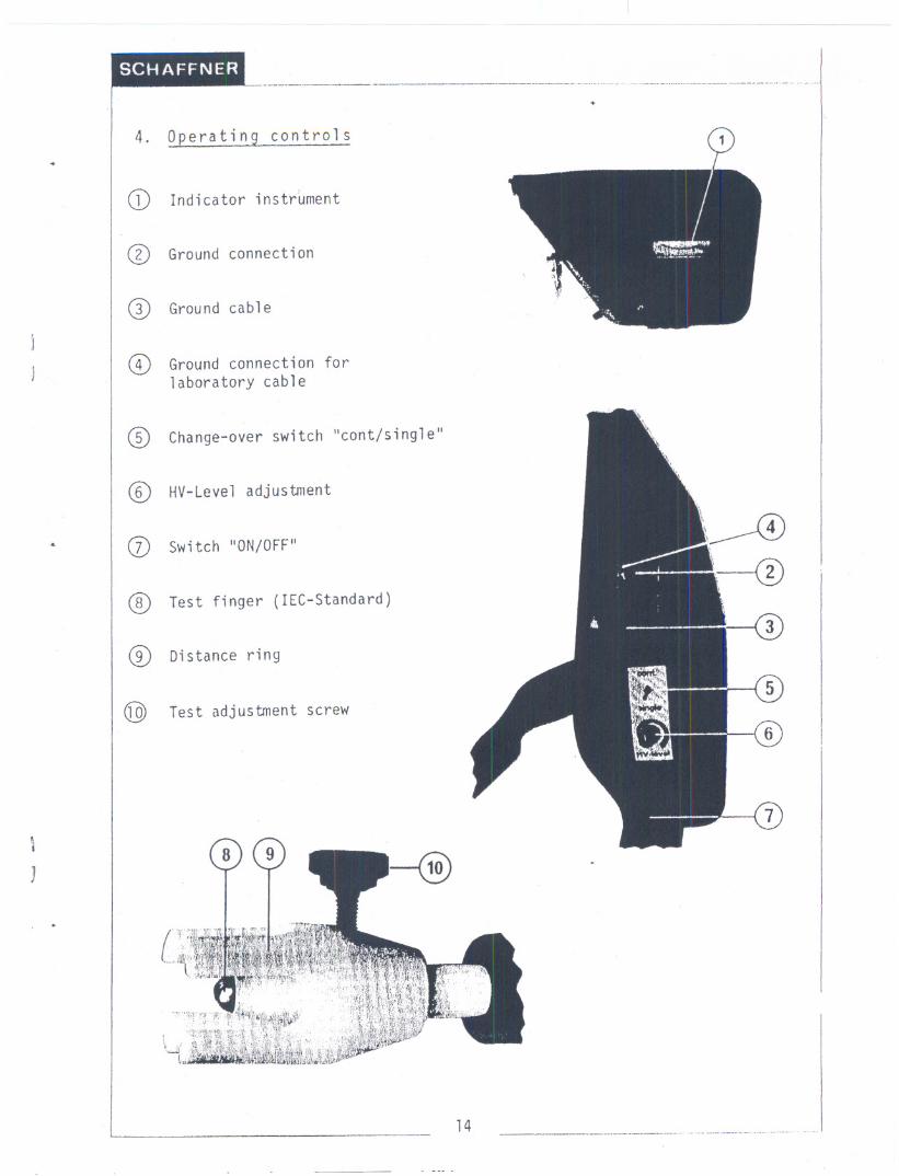
4. Operating controls
(i) Indicator instrument
(?) Ground connection
~ Ground cable
(1) Ground connection forlaboratory cable
@ Change-over switch Icont/sing1e"
CD HV-Leve1 adjustment
... (j) Switch "ON/OFF"
~ Test finger (IEC-Standard)
(2) Distance ring
@ Test adjustment screw
\
J
14 ___0 ---- .-"..-.
.----.----.-- , ._- --- - -.-.
.
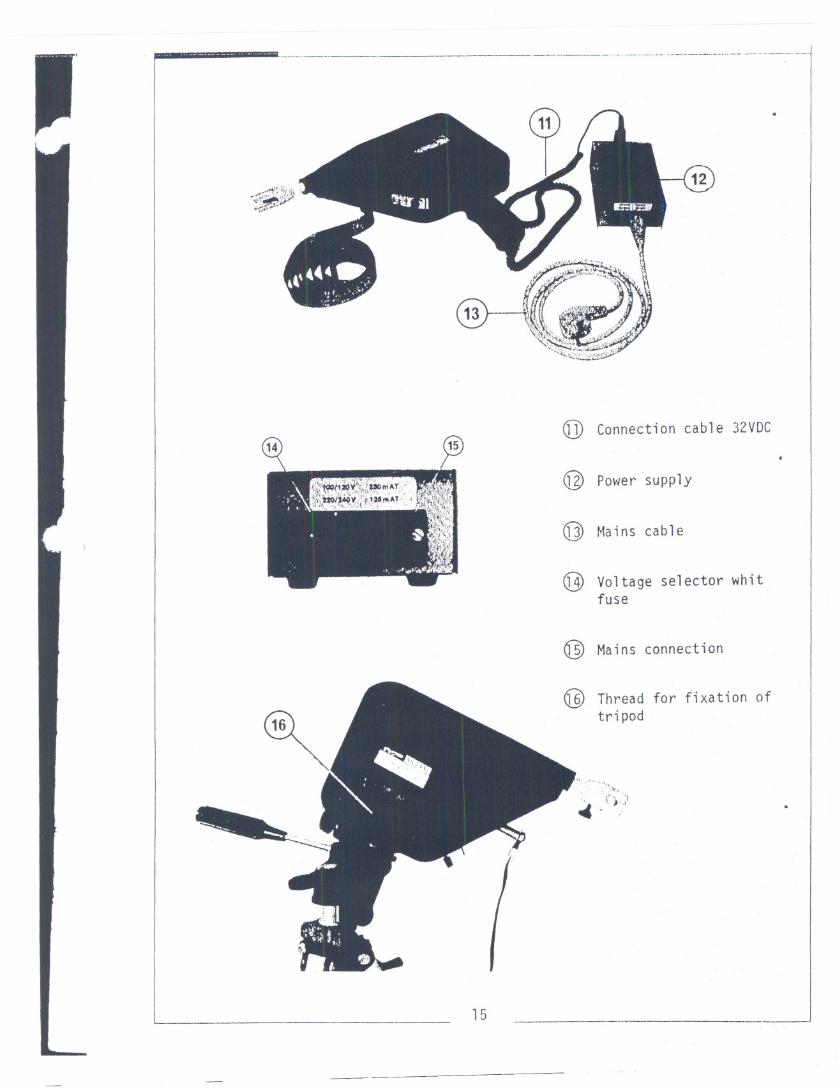
QJ) Connection cable 32VDC
(I:¥/" h~l~v:.~'1~( rri'AT.:...i:~\\;~""~,,:~w~ " ;','
;~~~~:~~;r:i1.~"'~T'.:.'~@ Power supply
@ Mains cable
@ Voltage selector whitfuse
@ Mains connection
@ Thread for fixation oftripod
. ".,,\" (. c,
.., . .)...'
15
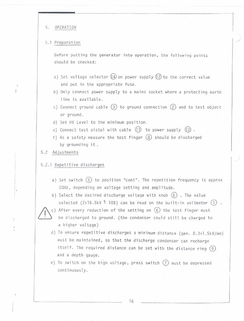
ll"J. OPERATION
5.1 Preparation
Before putting the generator into operation, the following points
should be checked:
a) Set voltage selector ([1) on power supply @ to the correct va1ue
and put in the appropriate fuse.
b) Only connect power supply to a mains socket where a protecting earth
line is available.
c) Connect ground cable CD to ground connection CD and to test object
or ground.
d) Set HV Level to the minimum position.
e) Connect test pistol with cable @ to power supply @ .f) As a safety measure the test finger (§) should be discharged
by ground i ng it .5.2 Adjustments
5.2.1 Repetitive discharges
Set switch @ to position "cont". The repetition frequency is approx
20Hz, depending on voltage setting and amplitude.
Select the desired discharge voltage with knob G[) . The value
selected (27l6.5kV t 10%) can be read on the built-in voltmeter CI)
After every reduction of the setting on C§) the test finger must
bedischarged to ground. (the conden~er could still be charged to
a higher vOltage)
To ensure repetitive discharges a minimum distance (gen. O.3+1.5kVjmm)
must be maintained, so that the discharge condenser can recharge
itself. The required distance can be set with the distance ring (2)and a depth gauge.
e) To switch on the high voltage, press switch (j) IllUSt be depressed
continuously.
------- 16
a)
I.!
I b)I
&)
d)

SCHAFFNER NSG 430~ , -.--....-
5.2.2 Single discharges
a) Set switch @ to position "single".
b) Select the desired voltage with knob ([) . The value selected
(2~16.5kV ! 10%) can be read on the built-in ~oltmeter CI) .
Ii\. c) After every reduction of the setting CD the test finger must be~ discharged to ground.
d) With switch CZ) the discharge condenser C will be charged once only.o
e) Slowly approach test object with the test finger (0.1 m/s) until
contact is made, in order that a guaranteed discharge takes place
at low voltages.
5.2.3 Continuous operation
The test generator was not developed for continuous operation or long
term investigations. Operating times in excess of lHr. should be
avoided,
a) Set switch @ to position "contll,
b) Select desired discharge voltage with
c) Press switch CZ) and in this position
knob @ .set switch @ to position
"single", Continuous operation is switched on.
d) Release switch (j) . The unit remains in operation,
e) The test finger must be discharged to ground after every reduction
of the discharge voltage.
f) Continuous operation can be switched off by switching over switch
CD to position IIcont", The press switch (j) should not be de-
pressed.
5.2.4 Tripod mounting..
The generator can be mounted onto a tripod by means of thread Q]D.
When testing, the required distance is set with the distance ring and
the tripod adjusted so that a slight pressure is obtained between the
distance ring and the test object. Thread type: UNC1/411I
. _ "n _.....___.___..._._._______ 17

NSG 430--.---- --------.-
5.3 BreakdownIecognition -.
Above approx. 2000Vdischarge voltage, discharges to HV
are indicated by an acousticsignal when switch ~ is
"single". (when several discharges occur consecutively
discharge cannot be indicated)
ground (1)
in positionhowever. each
5.4 Safetl
The maximumdischarge parameters are defined by IEC regulation
348.
Discharge before use,HV condensers have no discharge resi-
stances:
Discharge after use (single discharges would otherwise not be
possible)
Grounding compulsory (Protection class I)
Only use the unit in dry rooms.
Units with faulty covers may not be put into operation. Emergency
repairs do not fulfil the safety regulations.There is a high frequency current of approx 6 mAAC (measured
between HV-ground ~ and distribution system ground)
IAttention'
The return line of the HVdischarge should be always setted to the
ground connection ~ / ~ . If there is a discharge directly to
earth and the connection ~ / ~ is not connected to the same earth,electronic devices being close by may be disturbed or even destroyed.
Also NSG430 or 431 may be damaged.
18
-. .- - . -- -- -- - . - -

I
__h____._.___NSG 430
1------
6) TECHNICAL DATA
Discharge voltage Uo
Rise Time
Half amplitude width
Polarity
Discharge condenser Co
Discharge resistance Ro
Repetition frequency
Source resistance HV generator Rl
Hold time single (U -10%)
Supply voltages
Power consumption
Temperature range
Humidity
Suppression level
* Other values on request
Dimensions:
Test finger
Generator
Power supply
Ground cable
Carrying case
Weight:
Generator
Power supply
Accessories (included}:
SL 402 194SL 402 193SL 402 170SL 402 233SL 402 229
Carrying caseFuse setPower supplyTest fingerDistance setfor test fingerGround connectingcab 1e ( 2m)
SL 402 173
2kV to 16.5kV ~ 10%
5ns + 30% at 2kV
30ns :t 30% at 2kV
pos it i ve *+
150 pF * -+
150 ohm * -10%
5%
approx. 20Hz
100MQ.~ 10%
5s
100/120/220/240 VAC ! 10%50/60Hz
approx. 25 VA
5 - 40°C
20% - 80% (not condensing)
N (according to VOE0875)
~ 12x80 nm ~ 0.47x3.15"
260x300x56 nm 10.23"xll.81"x2.20"
160x91x56 nvn6.3"x3.58"x2.20"
approx. 2m 78.75"
520x375x125 mm20.47"x14.76"x4.92"
approx. 1.2kg
approx. 1. 1kg
2.65 1b
2.43 1b
Mains cable with plug according toorder number:SL 402 187 for D/F/NL/I/E/B/N/SFSL 402 188 for SwitzerlandSL 402 189 for ~SA and CanadaSL 402 033 without plug
Option
SL 402 283 Measuring adapter
19

SCHAFFNER NSG430'. ~---_._- --------------_.....--
7) EXAMPLESOF USAGE
In general measurements are made with single discharges. For
search and calibration a repetitive discharge is more useful.
The following examples are gathered together from recommen-
dations and guide lines.
1) Setting of the desired voltage and slowly approaching the
test object (approx. Otlm/s) until a discharge occurs.
2) Setting of the required distance (approx.Ot3 ~ 1t5 kV/mm)with the distance ring adjustment between the test finger
and the test object and then raising the voltage ~ntil a
discharge occurs.
Typical test set-up
gap ring
000000000000000
00000000
0000000
000000000000000
00000000
~800
430 .0000
o 00L.J 00o Coc coc 00
~------- -------- test obj ec t
connection
mainspower-supply
" " 20
SCHAFFNER 1'':>1.1 't.)U
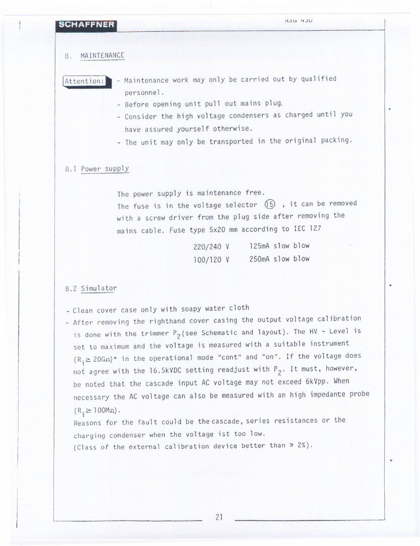
8. MAINTENANCE
!Attention:1I - Maintenance work may only be carried out by qualifiedpersonnel.
Before opening unit pullout mains plug.
Consider the high voltage condensers as charged until you
have assured yourself otherwise.
The unit may only be transported in the original packing.
13.1 Power supply
iI
I
I
II
The power supply is maintenance free.
The fuse is in the voltage selector QJD , it can be removed
with a screw driver from the plug side after removing the
mains cable. Fuse type 5x20 mmaccording to IEC 127
220/240 V
100/120 V
125mA slow blow
250mA slow blow
8.2 Simulator.
_ Clean cover case only with soapy water cloth
After removing the righthand cover casing the output voltage calibration
;s done with the trimmer P2(see Schematic and layout). The HV - Level is
set to maximumand the voltage is measured with a suitable instrument
(R.? 20Gfi)* in the operational mode "cont" and "on". If the voltage does,not agree with the 16.5kVDCsetting readjust with P2' It must, however,
be noted that the cascade input ACvoltage may not exceed 6kVpp. When
necessary the AC voltage can also be measured with an high impedance probe
( R . ~ 1 OOM!l) .1Reasons for the fault could be the cascade, series resistances or the
chargingcondenser when the voltage ist too low.
(Class of the external calibration device better than ~ 2%)...
21

":\ NSG 430--.-.--------.------.--.--
To calibrate the indicator instruments the right-hand cover case
has also to be removed. Then the output voltage must be measured with
a high resistance external meter (R. 20G ) at the test finger with1the unit in operation "cant" and "on". This measurement is then valid
for the calibration with P3 (see Schematic and layout) of the internalinstrument. The calibration current-which controls the 1 kV
indication-can be adjusted additionally by P4. The tolerance betweenthe indication value of the instrument in NSG 430/431 and the real
output voltage is as follows. ..
for < 5 kV:!:500 V
for > 5 kV :! 10 %
111
. !ii
,;;
Fuse set after removing the right-hand cover case (40OmAF/5x 20mm
according to IEC 127)
When the cover case is damaged it must be replaced. It is not permitted
to make a temporary repairt since the insulation can no longer beguaranteed.
8.3 Parts list and layoutI
8.4 Schematics
22

NSG 430/431------
9. MEASURING ADAPTER
The measuring adapter SL 402-283 is intended (in the first instance)
for use in measuring the discharge pulses .of the NSG 430 and NSG 431
equipments. The development of the measuring is based on an IEC stand-
ards draft 65 (see) 80. The following diagrams have been taken from thisdraft.
a) Equivalent electrical circuit of the generator
I <>- Dischargeelectrode100M.n. 150.n.
= I 2-16,5kV/ 21kV (s 150pF
II
I
iI
Functional earth
b) Equivalent electrical circuit of the measuring adapter
)1II
GenerCJtor I
NSG430,431 :
I
r:iJM1/2W
2n(S)(10nJ1W)
-- CRa
'::'
c) Mechanical construction of the measuring adapter (see mech. drg. 500 312
Dischargeelectrode
Matching resistor 50.0.
----.--
C><XI
GroundpIate Resistors in circular array (oax ial connector
T100
-._~ 23 -

SCHAFFNER NSG 430/431..--..-.-----.------.-
d) Discharge pulse definition
u
10.9 .
0,1 ~-
.5ns ~})%
3005 ! 30%
e) Complete measuring set-up
Main
Measuring adapterGroundplate
Powersupply
table
,~.,III,
1'1
" i\:
The oscilloscope required for the measurements must meet the
following specifications:
Storage capability
Rise time < 4.5 ns
Good EMC screening (ie not portable model)
---.. 24

SCHAFFNER NSG 430/431--
In order to obtain the specified data, proceed with the measurements
as follows:
5. Place NSG 430/431 in line with measuring adapter
G. Rapidly approach the measuring adapter sphere with the test finger
of the NSG 430/431 until they fully contact each other
7. Move test finter away from measuring adapter sphere
O. Read resulting measurement on CRO
JNote a
To avoid partial glow discharges and pre-ionisation, the test voltage
should be low and the approach speed high.
Measurements which are made according to this procedure ("measuring
adapter") and with necessary test set-up enable reproducable results
to be obtained as laid down in the lEC draft.
I
25
1- Switch CD to "cant" posi tion
2. Set discharge voltage to 2kV with knob
3. Depress button (j) and hold, then switch 0 to "single" position
4. Release button (j) (=>operational mode: operation over a long period)

NSG 430.--- ---,---....-...-- ----
.Elektronik-Print zu NSG 430 komplett
4
42 1 142-002 Drehknopf 021-2325
43 1 142-303 Deckel 040-1635
44 1 200-357 Ha1teb1ech I
45 1 200-358 " II
46 460nun 104-006 HV-Kabel F25 HV 2219
47
48 3 109-628 Schnorr-Sicherungssch hibe !-13
49 3 109-004 6-kt-Mutter 1'13
50
51 3 106-081 Pan-Head-Schraube N 3:8
52
53 1 402-234 Uebertrager
54 1 110-025 Koh1eschichtwid. 100n/o,25W/5% <.1455 1 120-561 Kondensator .1F/63 ....9
56
57 1 136-013 IC D-Flip-F1ops IC 4013 trC4
58
59 1 1.47-901 Warntongeber F/SHD 12
60 8r::m 103-000 Cu-Draht verzinnt 008
61 10cm 103-613 TQ-Li tze 0, 22mm2 r/w eo 1,4562 1. 133-502 G1immerscheibe 12x18 GS 220P
63 3 1 3 3 - 503 IsolierbUchse e5x3xl,9
64 1 118-085 'l'rimmerlMO/lin 70 WTD-K-C P4
65 1 110-075 Kohleschichtwid. l, SMO/O, 2 5WI 5"4 R15
Pas. Sick. Art. Nr./Lager Nr. Auttr. Bezelchnung Bestell-Nr.chemPas.

Pos. I Stck.
2
3
4
5
6
7
8
9
10
11
12
13
14
15
16
Pos. I Stck.
NSG 430
300' 031
"----.----------------.-.--------.---.-
2
3
4
5
6
7
8
9
10
11
12
13
14
15
16
17
18
19
20
21
1
1
1
1
1
120'426
114-704
1
1
1
1
110'126
1
2
1
1
1
1
1
1
1
200'062
200'063
200'321
106'082
109'004
109'628
Leiterplatte
Elektro1ytkond. 10~F
" 470~FMP-Kond. 1S0nF
PTC-wid. 3,5kO/6mA/~1
OV 20637
OOV 20735
SOV'" PM 271 M~Q63 100-
5330 - B 40!52, 7kO/0, SW/S%
~ ZPY36 06341
100V/8A BDW 73
B 2 50 C 800 S
Koh1eschichtwid.
Zenerdiode 36V/l,3W/
Transistor DarlingtoSi-Gleichrichter
Lotpilz
LotpilzWinkel
Kabelbinder
Pan-Head-Schraube
einfach
doppe1t
SST 1M-M
M3x10 DIN 8 SA
M3 DIN 934
zu M3
GS 220P
1lSs,c1lS3xl,9
Washer
6kt-Mutter
Schnorr-si-scheibe
Glimmerscheibe (12x18
IsolierbUchse
10-31-483-076 Item 29
Art. Nr./Lager Nr./ Auttr. I Bezeichnung
1
1
2
124-803_.-110-029112-787
Bastell-Nr.
Leiterplatte Kompl. zu
Stromversorgung NSG 430/431
oKeramikKondensator
Koh1eschichtwid.
Widerstand VR 68
ZusaI1UTlenste11ung
Art. Nr.lLager Nr.~ Bezeichnung
----------....------
500-255
Bestell-Nr.
4 &...g~ ..~v
':,
-/,.
?~'-
chemPos.
-R3
C4-ICl,3
CSR5R6
![vw%;nsg OÁsU]mvedicreserve.mum.edu/kalpa/grihya/vaikhanasa_grihya_sutram.pdf · vw%;nsg OÁsU]m ([VaikhŒnasa] ()](https://img.pdfslide.us/doc/110x75/5e10d1d4f9d8ca3fed65000b/vwnsg-osu-vwnsg-osum-vaikhnasa-.jpg)