Embed Size (px)
Citation preview
Advanced Technologies for the GOES-R Series and Beyond:
Medium Earth Orbits (MEO) as a Venue for Polar Wind Measurements
and Geo Microwave – No Moving Parts
Fourth GOES Users’ ConferenceMay 2, 2006
Broomfield, Colorado
Gerald Dittberner (NOAA), Ph.D., CCM, FRMetS
Advanced Systems Planning Division
NOAA Satellite and Information ServicePoster 54
MEO
Medium Earth Orbitfor
Continuous Polar Winds
MEO
Medium Earth Orbitfor
Continuous Polar Winds
This work was performed byAndrew J. Gerber, Jr., David M. Tralli, and Francois Rogez,
Jet Propulsion LaboratoryThe California Institute of Technology
With support from NOAA
3
The Grand Vision
• Measure anywhere on the globe, anytime, with any repeat time, and distribute data to anywhere in near real time
4
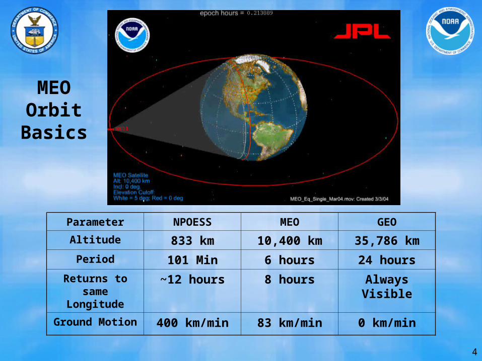
Parameter NPOESS MEO GEO
Altitude 833 km 10,400 km 35,786 km
Period 101 Min 6 hours 24 hours
Returns to same Longitude
~12 hours 8 hours Always Visible
Ground Motion 400 km/min 83 km/min 0 km/min
MEOOrbit
Basics
5
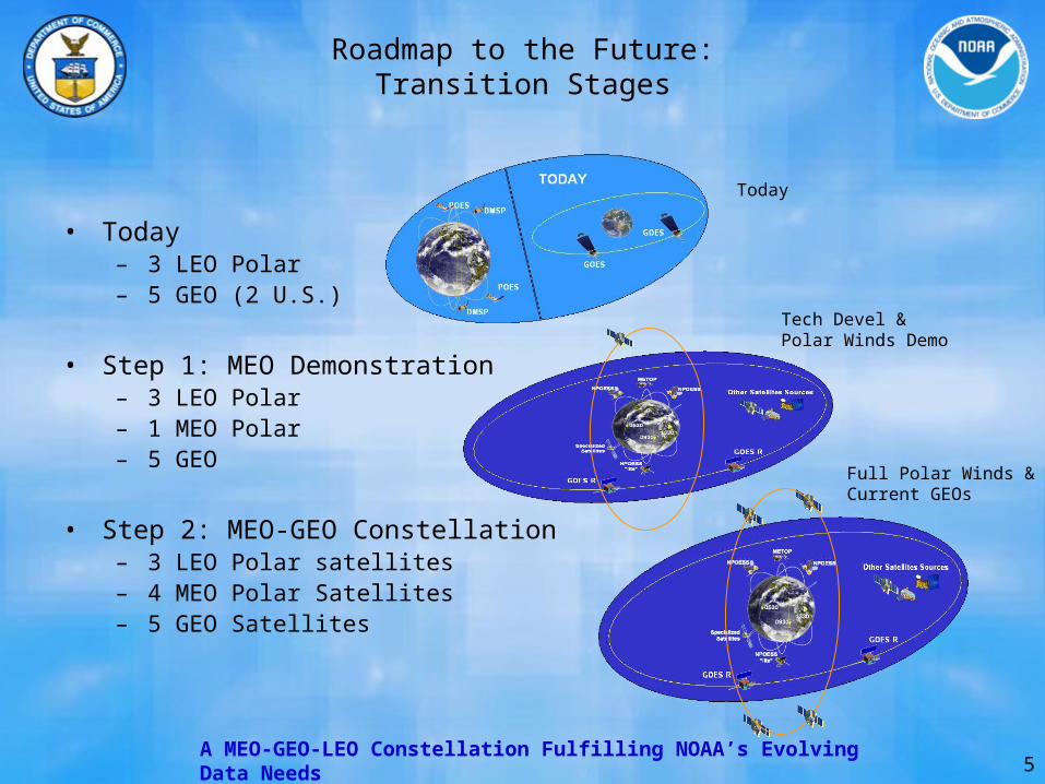
Roadmap to the Future:Transition Stages
• Today– 3 LEO Polar– 5 GEO (2 U.S.)
• Step 1: MEO Demonstration– 3 LEO Polar– 1 MEO Polar– 5 GEO
• Step 2: MEO-GEO Constellation– 3 LEO Polar satellites– 4 MEO Polar Satellites– 5 GEO Satellites
Tech Devel & Polar Winds Demo
Full Polar Winds &Current GEOs
A MEO-GEO-LEO Constellation Fulfilling NOAA’s Evolving Data Needs
Today
6
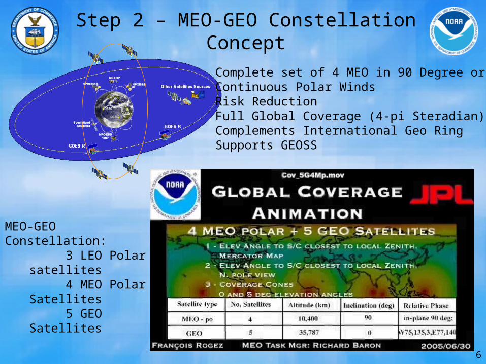
Step 2 – MEO-GEO ConstellationConcept
MEO-GEO Constellation: 3 LEO Polar satellites 4 MEO Polar Satellites 5 GEO Satellites
Complete set of 4 MEO in 90 Degree orbitContinuous Polar WindsRisk ReductionFull Global Coverage (4-pi Steradian)Complements International Geo RingSupports GEOSS
7
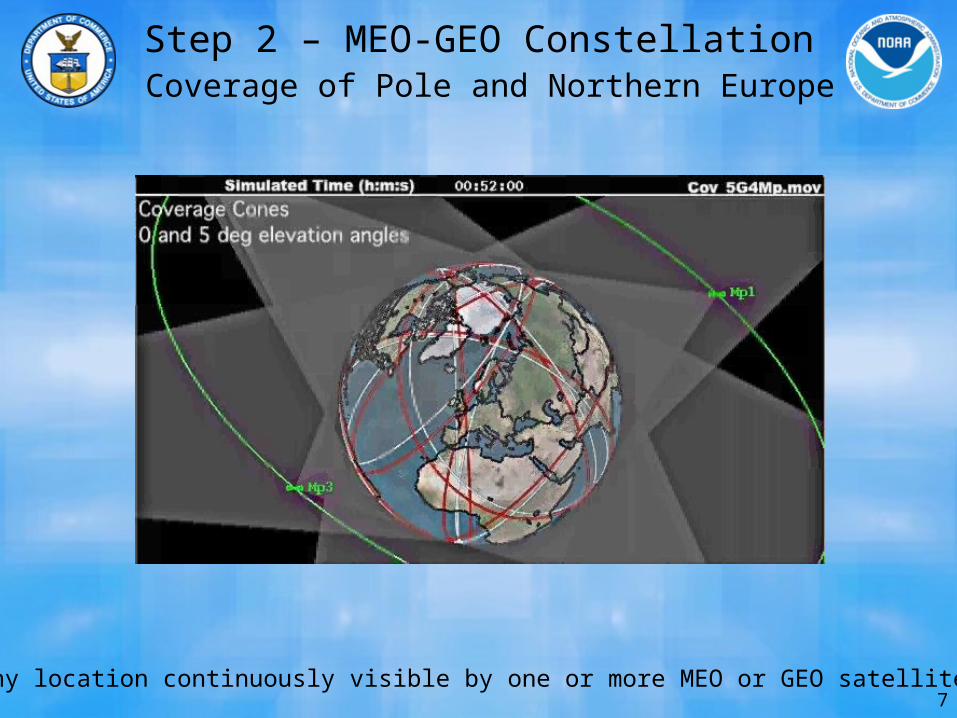
Step 2 – MEO-GEO Constellation Coverage of Pole and Northern Europe
Any location continuously visible by one or more MEO or GEO satellites
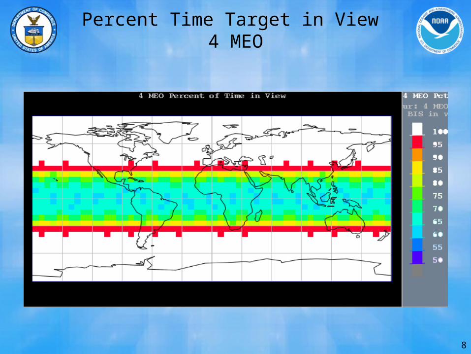
8
Percent Time Target in View 4 MEO
GeoSTARGeoSTAR
A Microwave SounderA Microwave Sounderforfor
GEO OrbitGEO Orbit
GeoSTARGeoSTAR
A Microwave SounderA Microwave Sounderforfor
GEO OrbitGEO Orbit
This was performed by:Bjorn Lambrigtsen (Lead), Shannon Brown, Steve Dinardo,
Pekka Kangaslahti, Alan Tanner, and William Wilson ofThe Jet Propulsion Laboratory, California Institute of Technology;
Jeff Piepmeier, GSFC; and Chris Ruf, U. MichiganThat was partially funded by NOAA
10
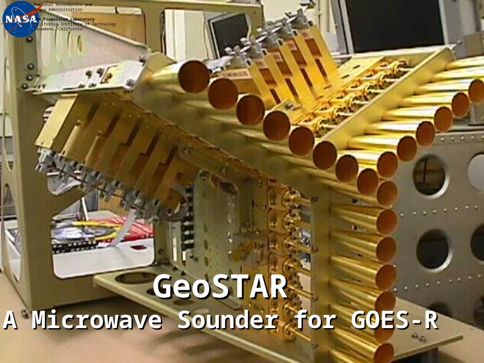
GeoSTARGeoSTARA Microwave Sounder for GOES-RA Microwave Sounder for GOES-R
National Aeronautics and Space Administration
Jet Propulsion LaboratoryCalifornia Institute of TechnologyPasadena, California
11
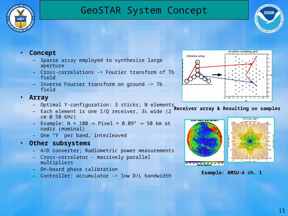
GeoSTAR System Concept
• Concept– Sparse array employed to synthesize large aperture– Cross-correlations -> Fourier transform of Tb field– Inverse Fourier transform on ground -> Tb field
• Array– Optimal Y-configuration: 3 sticks; N elements– Each element is one I/Q receiver, 3 wide (2 cm @
50 GHz)– Example: N = 100 Pixel = 0.09° 50 km at nadir
(nominal)– One “Y” per band, interleaved
• Other subsystems– A/D converter; Radiometric power measurements– Cross-correlator - massively parallel multipliers– On-board phase calibration– Controller: accumulator -> low D/L bandwidth
Receiver array & Resulting uv samples
Example: AMSU-A ch. 1
12
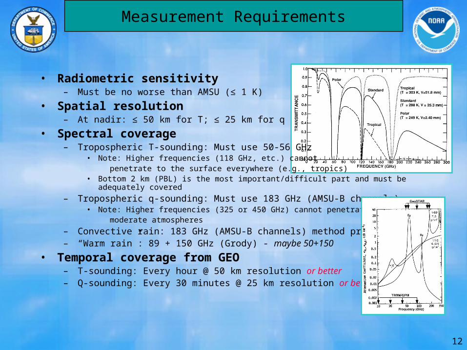
Measurement Requirements
• Radiometric sensitivity– Must be no worse than AMSU (≤ 1 K)
• Spatial resolution– At nadir: ≤ 50 km for T; ≤ 25 km for q
• Spectral coverage– Tropospheric T-sounding: Must use 50-56 GHz
• Note: Higher frequencies (118 GHz, etc.) cannot penetrate to the surface everywhere (e.g., tropics)• Bottom 2 km (PBL) is the most important/difficult part and must be adequately covered
– Tropospheric q-sounding: Must use 183 GHz (AMSU-B channels)• Note: Higher frequencies (325 or 450 GHz) cannot penetrate even moderate atmospheres
– Convective rain: 183 GHz (AMSU-B channels) method proven– “Warm rain”: 89 + 150 GHz (Grody) - maybe 50+150
• Temporal coverage from GEO– T-sounding: Every hour @ 50 km resolution or better– Q-sounding: Every 30 minutes @ 25 km resolution or better
13
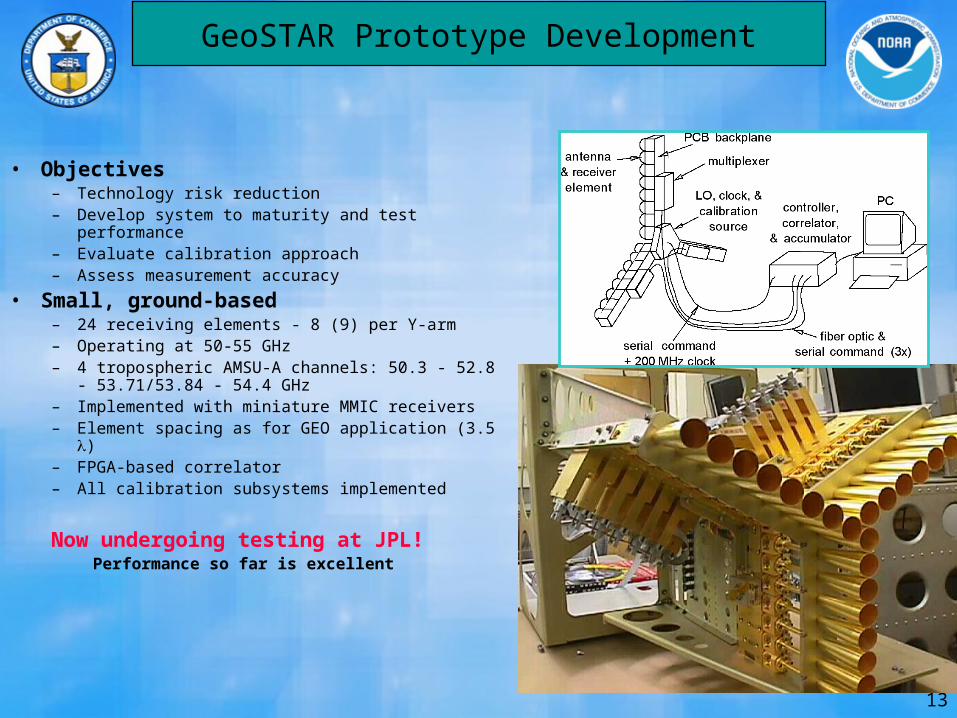
GeoSTAR Prototype Development
• Objectives– Technology risk reduction– Develop system to maturity and test performance– Evaluate calibration approach– Assess measurement accuracy
• Small, ground-based– 24 receiving elements - 8 (9) per Y-arm– Operating at 50-55 GHz– 4 tropospheric AMSU-A channels: 50.3 - 52.8 -
53.71/53.84 - 54.4 GHz– Implemented with miniature MMIC receivers– Element spacing as for GEO application (3.5 )– FPGA-based correlator– All calibration subsystems implemented
Now undergoing testing at JPL!Performance so far is excellent
14
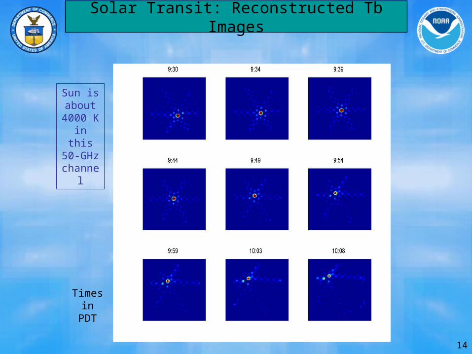
Solar Transit: Reconstructed Tb Images
Sun isabout
4000 Kin this
50-GHzchannel
Timesin
PDT
15
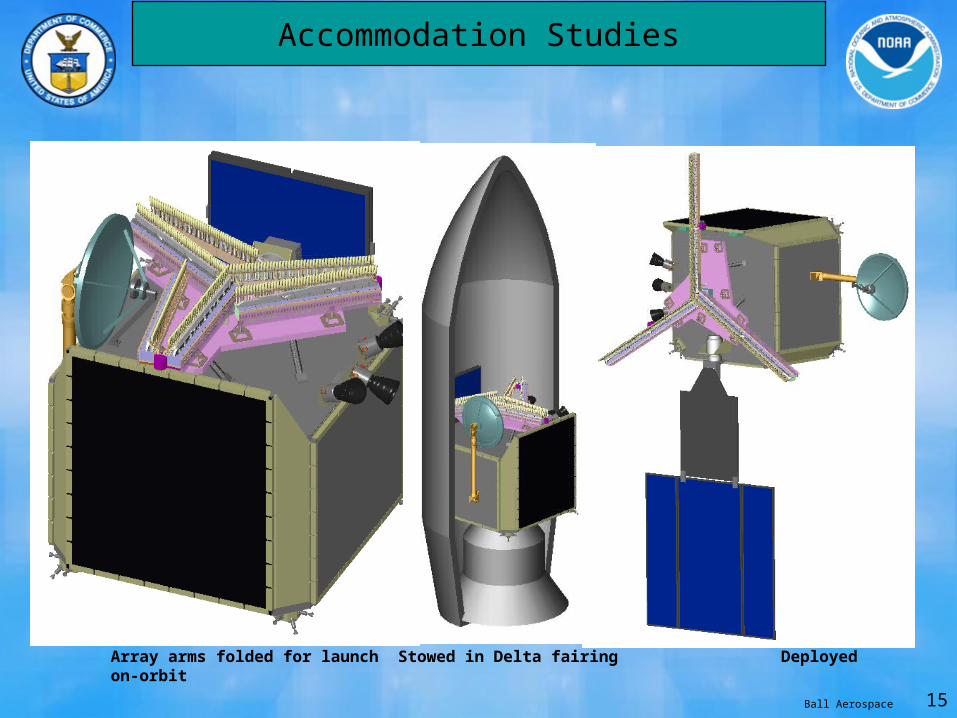
Accommodation Studies
Array arms folded for launch Stowed in Delta fairing Deployed on-orbit
Ball Aerospace

Backup Charts
17
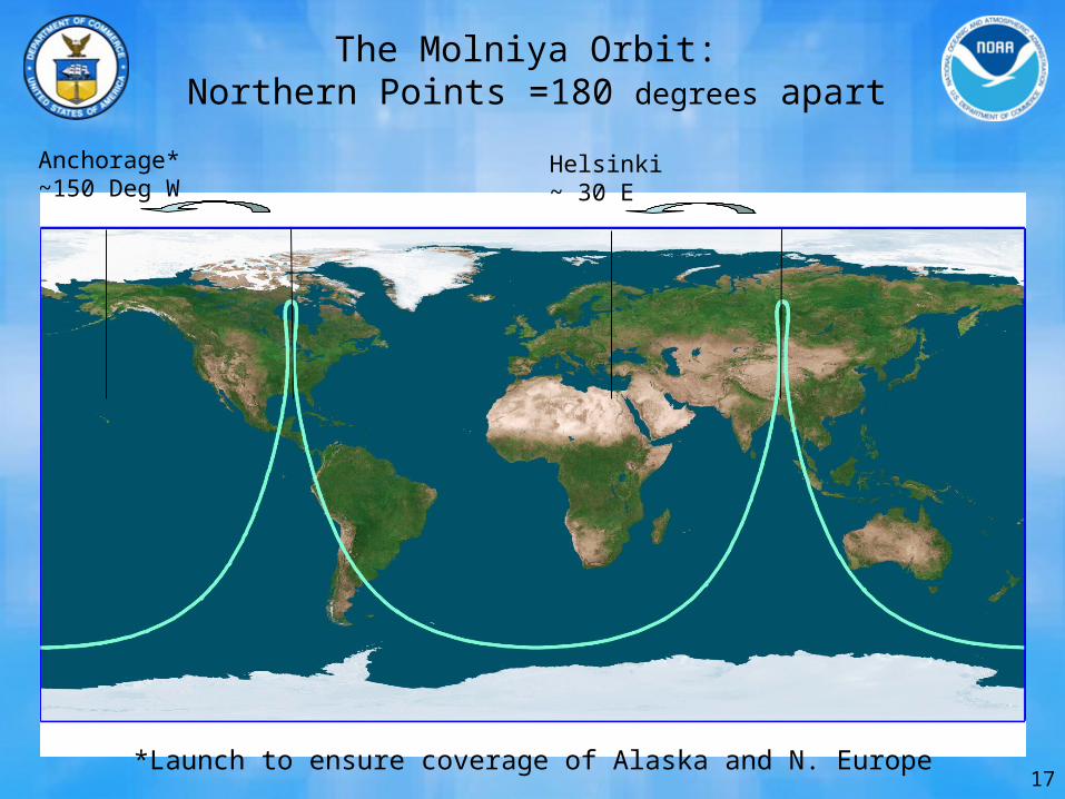
The Molniya Orbit: Northern Points =180 degrees apart
Anchorage*~150 Deg W
Helsinki~ 30 E
*Launch to ensure coverage of Alaska and N. Europe
18
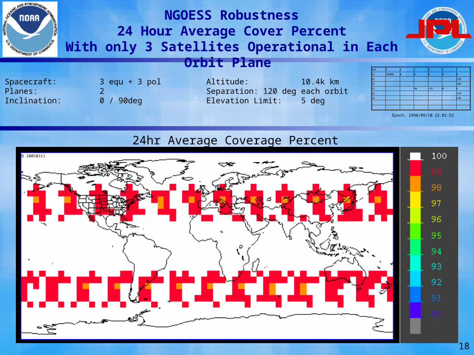
NGOESS Robustness24 Hour Average Cover Percent
With only 3 Satellites Operational in Each Orbit Plane
Spacecraft: 3 equ + 3 pol Planes: 2Inclination: 0 / 90deg
Altitude: 10.4k kmSeparation: 120 deg each orbitElevation Limit: 5 deg
24hr Average Coverage Percent
Epoch: 1998/09/10 22:02:52
sat H e i
e1 10400 0 0 0 0 0
e2 120
e3 240
p1 90 -35 0 0
p2 120
p3 240
FR 20050311
19Still
20
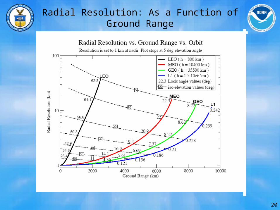
Radial Resolution: As a Function of Ground Range
21
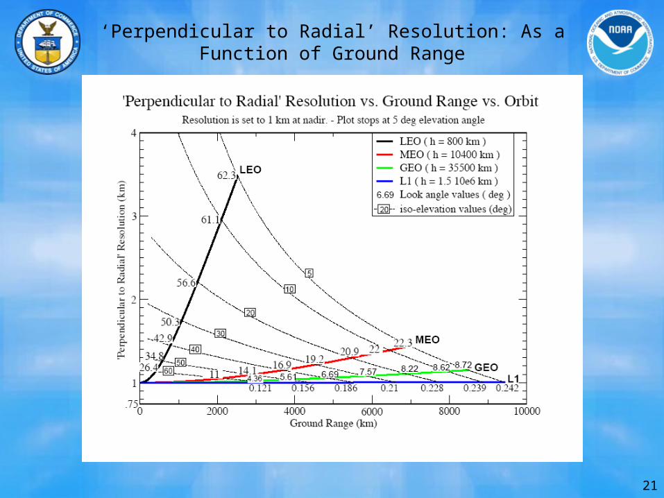
‘Perpendicular to Radial’ Resolution: As a Function of Ground Range
22
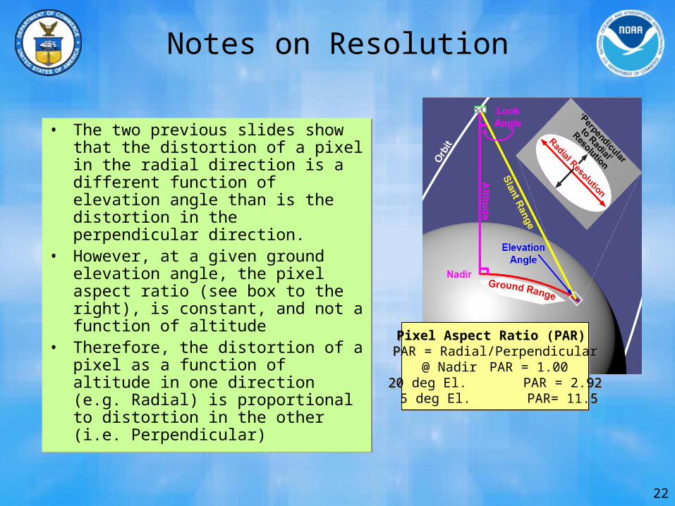
Notes on Resolution
• The two previous slides show that the distortion of a pixel in the radial direction is a different function of elevation angle than is the distortion in the perpendicular direction.
• However, at a given ground elevation angle, the pixel aspect ratio (see box to the right), is constant, and not a function of altitude
• Therefore, the distortion of a pixel as a function of altitude in one direction (e.g. Radial) is proportional to distortion in the other (i.e. Perpendicular)
Pixel Aspect Ratio (PAR) PAR = Radial/Perpendicular
@ Nadir PAR = 1.0020 deg El. PAR = 2.92 5 deg El. PAR= 11.5
Pixel Aspect Ratio (PAR) PAR = Radial/Perpendicular
@ Nadir PAR = 1.0020 deg El. PAR = 2.92 5 deg El. PAR= 11.5

![A Geostationary Equivalent Polar Observation System · 2020. 11. 26. · of high-latitudes and polar regions’ [19]. HEOs, such as the Molniya and Tundra orbits, have been used extensively](https://img.pdfslide.us/doc/110x75/60a02419adc81b1adc1c71a8/a-geostationary-equivalent-polar-observation-system-2020-11-26-of-high-latitudes.jpg)