Embed Size (px)
Citation preview

Advanced Teaching Materials for the Inverted Pendulum System by PLC Sequence Control
Junichi SUGAYA #1, Kuniaki YAJIMA #2, Yuta IISHIBA*3
#1ICT Development Center, #2Dept. Information Networks, National Institute of Technology Sendai College Sendai Miyagi, JAPAN
[email protected] [email protected]
*Graduate School of Informatics and Engineering, University of Electro-Communications, Chofu Tokyo, JAPAN
Abstract— Manufacture for beginners of the teaching materials by student’s proposals has been done fifth-year students’ practical training classes, in Dep. of Electronic Control Engineering, from 2010 to 2013. So we make this ideas develop some basic teaching materials of sequence control for international students and students in our college. Relay sequence control is the subject matter in these materials for beginners, because it is the foundation of sequence control. The purpose of manufacturing the materials is to enable students to understand the foundations of sequence circuits, such as logic circuit and self-hold circuit, using these teaching materials.Next, as an advanced step-up course of fundamental teaching materials, we developed new teaching materials whose subject is inverted-pendulum system. We selected the inverted-pendulum system, because it is unstable and it is possible to check the motion of pendulum visually. The objective of this inverted-pendulum system is to keep pendulum standing upright by using PLC-sequence control. The purpose of developing this teaching material is to enable students to understand sequence control. At present, we are testing the piecewise linear control for the inverted pendulum system, and we succeed to be able to keep it standing.
Keywords— Fundamental teaching-materials; PLC sequence control; Advanced teaching materials; Inverted pendulum system; Piecewise linear control
I. INTRODUCTION In modern society, the apparatus using automatic
control is applied in various fields. There are many kinds of automatic control, such as feedback control, feed-forward control, and sequence control. The sequence control is defined as "control which advances each stage one by one according to the order defined beforehand"[1]. In factory lines, it is embedded in machine tools and contributes to mechanical labour -saving. Moreover, sequence control is used in traffic signal systems or power plants, etc. Thus, we think that sequence control is a
fundamental technology widely used and is an important t e c h n o l og y wh i c h e n g i n e e r s s h ou l d s t u d y.
By the way, experiment and training courses for lower-class students in a National College of Technology are important because the courses raise their consciousness for “specialty”, and they also improve their training motivation towards specialized experiments in upper classes [2], etc. In our college, “Creative Engineering” course is started in the first year student in the new Dep. of Information System Engineering from 2010. Sequence control in Creative Engineering is selected as one topic in the old Dep. of Electronic Control Engineering of our college, and we decided to add some contents to further attract students’ interest in this topic and to cultivate their creativity.
In one of fifth-year students’ practical training of“Topics in Electronic Control” classes, students manufacture sequence control experiment materials and also develop teaching materials for the class, based on the donated five FA learning kits. In the process students’ creativity is harnessed, and the teaching materials are further developed for first-year students’ Creative Engineering class, and it will be improved every year. Development of the experiment materials and teaching materials are not teacher-led but based on students’ proposals [3]. First we report part of development process of a creative theme and its result in this paper.
On one hand, for beginners who learn about sequence control, teaching materials are necessary that actually help them to learn how to draw sequence ladder circuits and manufacture circuits, and to have training. For example, sequence control engineering is tried by some National Colleges of Technology [4].
So we next manufacture a new and similar teaching material to the donated FA learning kit and report about it. This material is for beginners with which learners can make the easy sequence circuits and receive training, and to use them in Creative Engineering class for first-year students or lessons for trainees from overseas [5]. Furthermore, teaching materials are required to be easy to wire and use. In these materials, we mainly use a contact sequence and learners can study logic circuits, such as
Journal of Engineering and TechnologyVol.4 No.2 July - December 2016
6

AND circuits, OR circuits, and NOT circuits, and fundamental sequence circuits.
On the other hand, we have been finding the sequence control engineering for graduation research works and application themes for overseas trainees since 2010. So we think of producing the inverted pendulum system which is well-known in the field of control as an application theme. Because inverted pendulum system is unstable and it is possible to check the pendulum visually. Inverted pendulums is utilized the apparatus in classes of automatic control in another college of technology [6]. And inverted pendulum model is applied to the human body to investigate the estimation method of the human postural control ability [7]. But the teaching materials of positioning control by sequence controller did nothing but know on enterprise training of Omron corp. and it was made for experts [8].
In this research advanced teaching materials is made by using basic teaching materials applied sequence control engineering finally and is reported. It is expected to be used in classes of the advanced course or in classes for overseas trainees. It also seems effective for delivering lessons and for demonstrations.
II. FUNDAMENTAL EXPERIMENT
Sequence control is taught in Creative Engineering class for first-year students, in Topics in Electronic Control for fifth-year students, and in lessons for foreign trainees, and these classes are experiment and training courses using the basic FA learning kit [9] of OMRON Corp. A. Basic sequence control experiment
A package box of FA learning kit contains sensors, relays, a switch and so on, with which students can conduct experiments and practical trainings with fundamental contents of sequence control. Students can realize a self-hold circuit or other circuits only by placing and wiring each sequence element onto the conveyor equipment in the FA learning kit. They can also place a timer or a counter on it, and conduct experiments with photo-electronic sensors.
First-year students in our department have used this teaching materials kit for experiments and practical training with fundamental sequence control from 2010, but there are not enough applied topics. So we need some topics more similar to the reality. Some topics requiring creativity will have to interest in the lower-class students. Therefore, we determined that fifth-year students in our department should create the topic contents while they study sequence control, since second-year students and older have not learned sequence control in class.
We decided to perform this practical training in “Topics in Electronic Control” class for fifth-year students. Students will develop teaching materials within thirteen two-hour classes in the second semester.
B. Proposal-type teaching materials in practical training (1) Students conduct basic experiments of
“Creative Engineering” for first-year students in the first three classes (Fig. 1).
(2) Students propose applied creative themes based on basic knowledge of sequence control.
(3) Teachers in charge scrutinize the contents of students’ proposals.
(4) Students put the new theme into exact writing and design the ladder diagram based on it.
(5) Students choose necessary parts on the Internet. (6) Students carry out actual manufacture on a
circuit stationary plate. (7) Students conduct the trial experiment by the FA
learning kit. (8) Students presents about the manufactured
teaching materials and reported it. For example, in (7), students check whether the
operation according to the devised theme is possible, and complete reproducible teaching materials. The cleaning robot that students manufactured in 2012 is given as an example, which is shown Fig. 2.
However, the lesson is performed for one class unit in many cases, but we have only five sets of teaching materials, which are too few for the number of students. Since the teaching materials are few and the number of students who use one set of the material is too large, learning efficiency should surely fall and, as a result, the students may be unable to study the contents correctly. Although to increase the number of teaching materials is desirable as a solution to this problem, their prices make it difficult to purchase more materials; the price of one set of teaching materials is as expensive as about 1 million yen.
Fig.1 Basic experiment of sequence circuit
Journal of Engineering and TechnologyVol.4 No.2 July - December 2016
7

Fig. 2 The cleaning robot manufactured in 2010
Therefore, we try to improve learning efficiency by making teaching materials by ourselves at low costs and in large numbers and having students use them.
C. Manufacture of teaching materials for beginners
The electric power unit and the breaker which is used only at the time of power activation were installed in the topmost part so that an experimenter could not touch the fundamental parts. The switch and the display light were installed in the upper part, and each terminal box was grouped in the center so that an experimenter could wire easily. The DIN rail was installed in the lower part so that it would be easier to wire and to remove sockets.
1) Manufacture of first experimental model The experimental model was manufactured. In this
experimental model, parts were installed on a veneer board of depth 350 [mm], width 450 [mm] and height 5 [mm]. Moreover, the questionnaire was carried out in order to add improvement. After we actually had students make the push button circuit and a self-hold circuit in this questionnaire, and we investigated how easy it is to carry out the work by it.
As a result of having students answer to the question whether or not they have found any part hard to use, the five students who actually used these teaching materials answered is shown Table 1. We remake the improved teaching material based on these opinions that are answers of Table 1. New material is show in next section.
TABLE1
.RESULT OF QUESTIONNAIRE
2) Manufacture of improved teaching materials Here the teaching materials which improved more
teaching materials for beginners are proposed and
manufactured. In this model, parts were installed on an acrylic board of depth 350[mm], width 450[mm] and height 5 [mm]. The reasons for having used an acrylic board are from next three conditions.
(1)-First condition: It is an insulator whose resistivity is 1015 [Ω・m].
(2)-Second condition: The cost is low. (3)-Third condition: Since it is highly transparent, it
can visualize back wiring. This model based on the opinions that are answers of
Table 1in the questionnaire about the experimental model. The design of the actual equipment is shown in Fig.3. In order to avoid some accidents, such as wiring on the back being pulled and separated, it was tucked between two acrylic boards.
Fig.3 Design of Teaching Material
The bill of materials used for the teaching materials is
shown in Table 2. The 19 parts in 10 kinds were used for these teaching materials. The expense was 15,374 yen in total since we used the acrylic boards. Compared with basic FA learning kits, the cost was able to be sharply held down for these teaching materials.
TABLE2
BILL OF MATERIAL
The photo of the completed teaching material seen from above is shown in next page’s Fig. 4. We provide the completed teaching material to student from the partner university and ask the feeling. As a result of having student answer to the question is no problem to use as teaching martial.
Journal of Engineering and TechnologyVol.4 No.2 July - December 2016
8

D. Making of the circuit production manual We made the circuit manual to use as a text of the
teaching materials. At present, FA kit manual is used as a text in class. It explains relay and the sensor to use by sequence control, but it isn’t writing method of make the circuit.
We made the new manual based on that view. It is correspondent to the improved sequence teaching materials.
This manual explains the concrete method for making four type kinds of circuits which are important circuits. Four circuits are fundamental circuit (ON, OFF SW circuit), logical circuit (AND, OR circuit), Relay circuit (NOT, Self-holding circuit) and Applied circuit (Delay, Interlock circuit). We increase figures to make it intelligible because this text is a product for beginners.
Fig.4 Top View of Teaching Material
III. INVERTED PENDULUM SYSTEM BY PLC An application system of inverted pendulum is
manufactured by sequence control engineering and an experiment with the production is conducted by using these basic teaching materials in this research. A. Outline
The layout drawing of inverted pendulum system produced in this research is shown in Fig.5. Our system consists of three sections: the control section is a PLC as the controller, the actuator section consisting of a potentiometer as an angle sensor and the pendulum section is a servo motor, and a cart with a pendulum made of an aluminum square bar with ball-screw-stage as the controlled object. First, a potentiometer detects the angle information of the pendulum in current. Next the PLC carries out a control operation by using the angle information. The angle information from the potentiometer and revolving information on the motor from the encoder are fed back to the PLC. The operation result is sent in PWM form to the servomotor as the order voltage. The ball screw stage moves to left and right by a revolution of a servomotor, and the pendulum installed in the stage revolves. The controlled object is controlled based on the position information from the potentiometer,
and the pendulum is kept upright as the cart moves by the signal that the controller generates.
Therefore, the objective of this inverted-pendulum system is to keep pendulum standing upright. In order to achieve this objective, we divided the control part into two: the one to swing-up the pendulum [10] and the one to keep it standing upright. The control range of the former is within an angle area of ±15 [deg] based on pendulum standing, and the swing-up control part is within an angle area of excluding ±15 [deg].
Fig.5 Inverted pendulum system by PLC
Fig.6 shows the parameters of the pendulum system
for numerical linearized model [11] of nonlinear inverted-pendulum system. The numerical formula of this model is obtained from the state space method by leading a motion equation. These parameter is used in the next MATLAB simulink simulation.
Fig.6 Inverted pendulum system model and system’s parameter
B. MATLAB simulation
Before the experiment, we analyze unit step response for the linearized inverted pendulum system using the MATLAB simulink simulation. The result of analysis is shown in Fig.7.
Journal of Engineering and TechnologyVol.4 No.2 July - December 2016
9

Fig.7 Analytic response (MATLAB simulink simulation)
The analysis-condition of state-space model is; the sampling period is 100[ms] and the step-size is 0.1. From the Fig.7, we can see that the angle of the pendulum converges into 0 [deg].Even if the cart location was moved 0.22 [m] in simulation, the pendulum angle converged, and we were able to judge that standing control was possible. Therefore, we tried an experiment of standing control by using the inverted pendulum device.
C. Experiment by equipment
In this equipment we will control by dividing the construction into two control parts; the standing upright control one and the swing up control one. Fig.8 shows the control angle areas of the inverted pendulum system that we made. The control target of the main system is to swing up the pendulum in a suspension state and to keep it standing upright. A boundary in a standing upright control area (this area is used for the judgment of angle condition of the standing upright state) is compared about a change in standing upright keeping time when a control angle area is changed from -12 to -5 [deg] and from 5 to 12 [deg].
The respective control areas are distinguished by the angle of the pendulum. Piecewise linear control is applied to PLC sequence control. If the angle of the standing upright state is set at 0 [deg], it means, for example, the standing upright control area is the range of ±10 [deg], all except it was made a control area for the pendulum is to be swung up.
Fig.8 Control angle ranges
We checked the longest standing upright time of the
pendulum at angles of ±5 [deg], ±7 [deg], ±10 [deg] and
±12 [deg] respectively with servomotor’s revolution speed fixed at 2000[ rpm]. Table 3 shows the standing upright time of each control area. Under this condition, the longest standing time is 8.7 seconds at the angle of ±10 [deg]. Considering standing upright time, it can be said that the control result is good at the angle of ±10 [deg].
D. Flow chart
Here we explain it by using a flow chart. A flow chart of swing up control algorithm is shown in
Fig. 9. The direction of rotation of the servomotor is decided from each reach of the angle in this swing up control.
When it is in the reach of the swing up control (between during from -180 to -10 [deg], and between from 10 to 180 [deg]), we can distinguish whether the pendulum is up or down by comparing the current angle position (θN) and the previous angle position (θN-1). For easiness, θN and θN-1 are abbreviated to N and N-1 respectively.
TABLE3
COMPARISON IN STANDING UPRIGHT TIME
Fig.9 Flow chart of swing up control
Fig.10 shows the flow chart of standing upright control
part. When the pendulum goes up by swing up control and passes 0 [deg], it is taken over by standing upright control. When the angle of the pendulum is between -10 and 10 [deg], the servomotor revolves in CW (Clock Wise) and CCW (Counter Clock Wise) direction, and the stage is moved. The stage accelerates and the torque spins the pendulum, and the pendulum revolves.
Journal of Engineering and TechnologyVol.4 No.2 July - December 2016
10
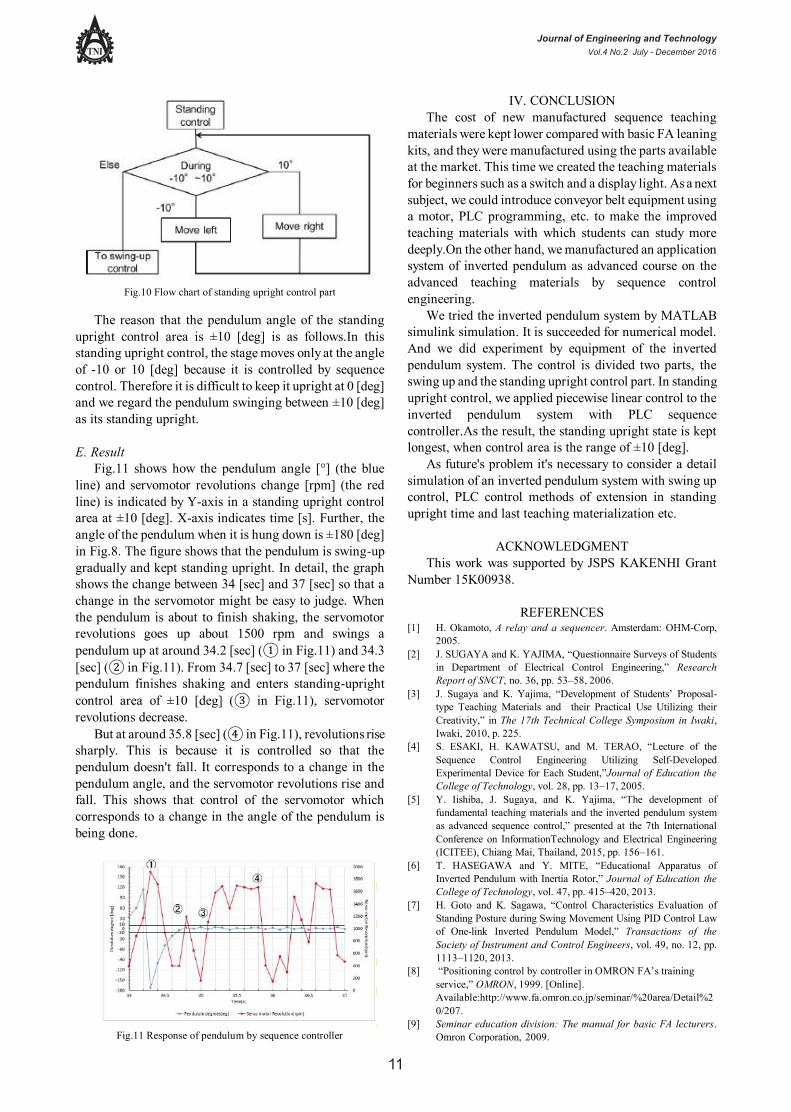
Fig.10 Flow chart of standing upright control part
The reason that the pendulum angle of the standing
upright control area is ±10 [deg] is as follows.In this standing upright control, the stage moves only at the angle of -10 or 10 [deg] because it is controlled by sequence control. Therefore it is difficult to keep it upright at 0 [deg] and we regard the pendulum swinging between ±10 [deg] as its standing upright.
E. Result
Fig.11 shows how the pendulum angle [°] (the blue line) and servomotor revolutions change [rpm] (the red line) is indicated by Y-axis in a standing upright control area at ±10 [deg]. X-axis indicates time [s]. Further, the angle of the pendulum when it is hung down is ±180 [deg] in Fig.8. The figure shows that the pendulum is swing-up gradually and kept standing upright. In detail, the graph shows the change between 34 [sec] and 37 [sec] so that a change in the servomotor might be easy to judge. When the pendulum is about to finish shaking, the servomotor revolutions goes up about 1500 rpm and swings a pendulum up at around 34.2 [sec] (① in Fig.11) and 34.3 [sec] (② in Fig.11). From 34.7 [sec] to 37 [sec] where the pendulum finishes shaking and enters standing-upright control area of ±10 [deg] (③ in Fig.11), servomotor revolutions decrease.
But at around 35.8 [sec] (④ in Fig.11), revolutions rise sharply. This is because it is controlled so that the pendulum doesn't fall. It corresponds to a change in the pendulum angle, and the servomotor revolutions rise and fall. This shows that control of the servomotor which corresponds to a change in the angle of the pendulum is being done.
Fig.11 Response of pendulum by sequence controller
IV. CONCLUSION The cost of new manufactured sequence teaching
materials were kept lower compared with basic FA leaning kits, and they were manufactured using the parts available at the market. This time we created the teaching materials for beginners such as a switch and a display light. As a next subject, we could introduce conveyor belt equipment using a motor, PLC programming, etc. to make the improved teaching materials with which students can study more deeply.On the other hand, we manufactured an application system of inverted pendulum as advanced course on the advanced teaching materials by sequence control engineering.
We tried the inverted pendulum system by MATLAB simulink simulation. It is succeeded for numerical model. And we did experiment by equipment of the inverted pendulum system. The control is divided two parts, the swing up and the standing upright control part. In standing upright control, we applied piecewise linear control to the inverted pendulum system with PLC sequence controller.As the result, the standing upright state is kept longest, when control area is the range of ±10 [deg].
As future's problem it's necessary to consider a detail simulation of an inverted pendulum system with swing up control, PLC control methods of extension in standing upright time and last teaching materialization etc.
ACKNOWLEDGMENT
This work was supported by JSPS KAKENHI Grant Number 15K00938.
REFERENCES
[1] H. Okamoto, A relay and a sequencer. Amsterdam: OHM-Corp, 2005.
[2] J. SUGAYA and K. YAJIMA, “Questionnaire Surveys of Students in Department of Electrical Control Engineering,” Research Report of SNCT, no. 36, pp. 53–58, 2006.
[3] J. Sugaya and K. Yajima, “Development of Students’ Proposal-type Teaching Materials and their Practical Use Utilizing their Creativity,” in The 17th Technical College Symposium in Iwaki, Iwaki, 2010, p. 225.
[4] S. ESAKI, H. KAWATSU, and M. TERAO, “Lecture of the Sequence Control Engineering Utilizing Self-Developed Experimental Device for Each Student,”Journal of Education the College of Technology, vol. 28, pp. 13–17, 2005.
[5] Y. Iishiba, J. Sugaya, and K. Yajima, “The development of fundamental teaching materials and the inverted pendulum system as advanced sequence control,” presented at the 7th International Conference on InformationTechnology and Electrical Engineering (ICITEE), Chiang Mai, Thailand, 2015, pp. 156–161.
[6] T. HASEGAWA and Y. MITE, “Educational Apparatus of Inverted Pendulum with Inertia Rotor,” Journal of Education the College of Technology, vol. 47, pp. 415–420, 2013.
[7] H. Goto and K. Sagawa, “Control Characteristics Evaluation of Standing Posture during Swing Movement Using PID Control Law of One-link Inverted Pendulum Model,” Transactions of the Society of Instrument and Control Engineers, vol. 49, no. 12, pp. 1113–1120, 2013.
[8] “Positioning control by controller in OMRON FA’s training service,” OMRON, 1999. [Online]. Available:http://www.fa.omron.co.jp/seminar/%20area/Detail%20/207.
[9] Seminar education division: The manual for basic FA lecturers. Omron Corporation, 2009.
Journal of Engineering and TechnologyVol.4 No.2 July - December 2016
11

[10] N. Fujiki, K. Kanzaki, and R. Matsuda, “Swinging-Up Motion and Upside-Down Standing of Pendulum with Inertia Rotor,” Transactions of the Japan Society of Mechanical Engineers Series C, vol. 68, no. 667, pp. 810– 816, 2002.
[11] I. MORISHITA and T. UENO, Digital control engineering. Amsterdam: OHM Corp, 1987.
Journal of Engineering and TechnologyVol.4 No.2 July - December 2016
12