Embed Size (px)
Citation preview
1
Advanced Structural Analysis
Prof. Devdas Menon
Department of Civil Engineering
Indian Institute of Technology, Madras
Module No. 2.1
Lecture No. 07
Review of Basic Structural Analysis-2
Good morning to you.
(Refer Slide Time: 00:20)
This is lecture 7 in the second module on Review of Basic Structural Analysis.
2
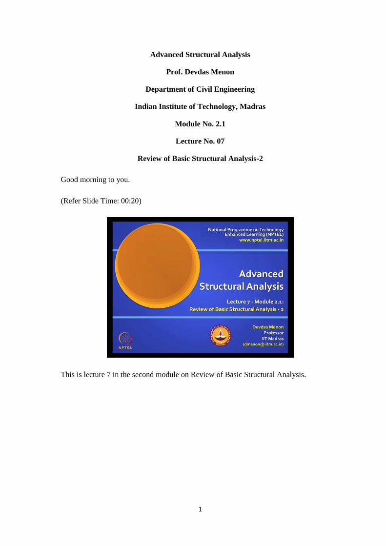
(Refer Slide Time: 00:27)
We finished the first review where we covered statically determinate structures. Now, we
are going to look at statically indeterminate structures, as well as kinematically
indeterminate structures.
(Refer Slide Time: 00:34)
The first three lectures in this part will deal with force methods, as applied to statically
indeterminate structures; you've already had an exposure to this in your earlier course.
So, I will go a little fast.
3
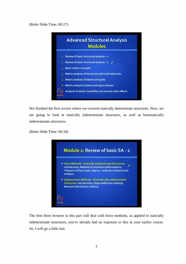
(Refer Slide Time: 00:51)
As mentioned earlier, we are going to refer to this book on structural analysis, part IV:
Statically Indeterminate Structures - Force Methods.
(Refer Slide Time: 00:59)
You really have not got much exposure to displacement methods, but you had some
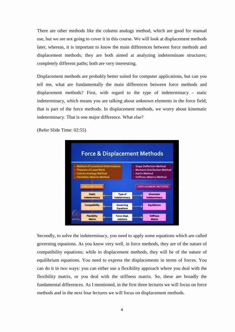
exposure to force methods. The most popular force methods are: The methods of
consistent deformations and Theorem of least work, which you have been introduced to.
These lead to a more generalized method called flexibility matrix method, which we will
study in depth in this course.
4
There are other methods like the column analogy method, which are good for manual
use, but we are not going to cover it in this course. We will look at displacement methods
later, whereas, it is important to know the main differences between force methods and
displacement methods; they are both aimed at analyzing indeterminate structures;
completely different paths; both are very interesting.
Displacement methods are probably better suited for computer applications, but can you
tell me, what are fundamentally the main differences between force methods and
displacement methods? First, with regard to the type of indeterminacy - static
indeterminacy, which means you are talking about unknown elements in the force field;
that is part of the force methods. In displacement methods, we worry about kinematic
indeterminacy. That is one major difference. What else?
(Refer Slide Time: 02:55)
Secondly, to solve the indeterminacy, you need to apply some equations which are called
governing equations. As you know very well, in force methods, they are of the nature of
compatibility equations; while in displacement methods, they will be of the nature of
equilibrium equations. You need to express the displacements in terms of forces. You
can do it in two ways: you can either use a flexibility approach where you deal with the
flexibility matrix, or you deal with the stiffness matrix. So, these are broadly the
fundamental differences. As I mentioned, in the first three lectures we will focus on force
methods and in the next four lectures we will focus on displacement methods.
5
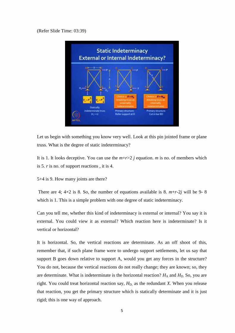
(Refer Slide Time: 03:39)
Let us begin with something you know very well. Look at this pin jointed frame or plane
truss. What is the degree of static indeterminacy?
It is 1. It looks deceptive. You can use the m+r>2 j equation. m is no. of members which
is 5. r is no. of support reactions , it is 4.
5+4 is 9. How many joints are there?
There are 4; 4×2 is 8. So, the number of equations available is 8. m+r-2j will be 9- 8
which is 1. This is a simple problem with one degree of static indeterminacy.
Can you tell me, whether this kind of indeterminacy is external or internal? You say it is
external. You could view it as external? Which reaction here is indeterminate? Is it
vertical or horizontal?
It is horizontal. So, the vertical reactions are determinate. As an off shoot of this,
remember that, if such plane frame were to undergo support settlements, let us say that
support B goes down relative to support A, would you get any forces in the structure?
You do not, because the vertical reactions do not really change; they are known; so, they
are determinate. What is indeterminate is the horizontal reaction? HA and HD. So, you are
right. You could treat horizontal reaction say, HD, as the redundant X. When you release
that reaction, you get the primary structure which is statically determinate and it is just
rigid; this is one way of approach.
6
Let me ask, if you can treat the same problem as internally indeterminate? Yes, that
option is also there. You could remove which member or cut which member? Anyone of
those members can be removed, not necessarily the diagonal; the diagonal is what we
normally remove. Can you remove the member to get the primary structure or should
you cut it? Some text books mention about removing members, which is fine in one
sense, but inaccurate in the other sense. You will find that, if you cut that member, it will
have no force; if you remove it also, it will have no force. But if you cut it and apply the
unknown redundant - a pair of equal and opposite tensile forces, as shown there, then
you are also invoking the stiffness or the flexibility of that member, which would be
missing if you remove that member all together. So, the stiffness of that member BD has
a role in governing the answer of X. So, do not remove members; you just cut them.
When you cut them, you release the member. We will examine this more carefully, later.
So, we have multiple choices of indeterminacy and it is left to you whether to treat this
problem either externally or internally indeterminate.
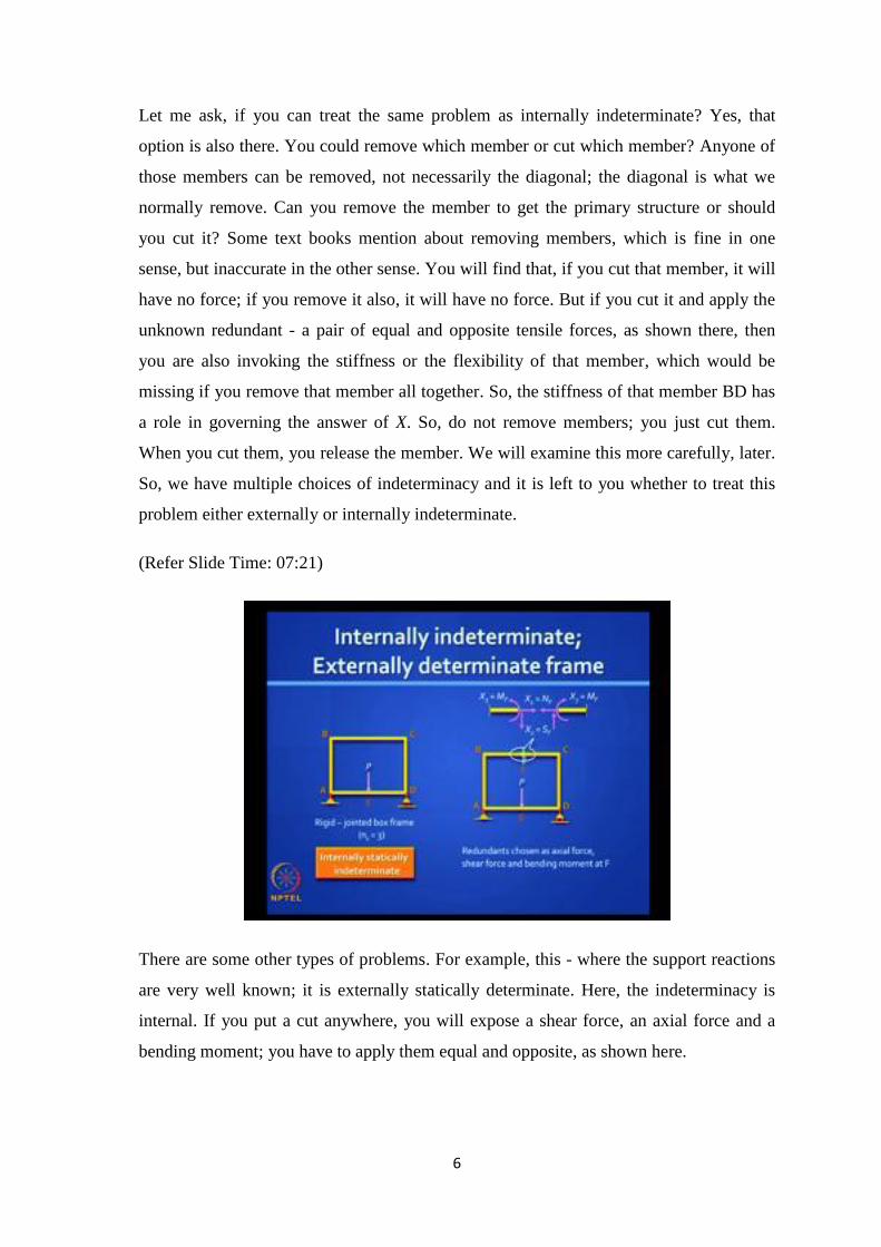
(Refer Slide Time: 07:21)
There are some other types of problems. For example, this - where the support reactions
are very well known; it is externally statically determinate. Here, the indeterminacy is
internal. If you put a cut anywhere, you will expose a shear force, an axial force and a
bending moment; you have to apply them equal and opposite, as shown here.
7
(Refer Slide Time: 07:45)
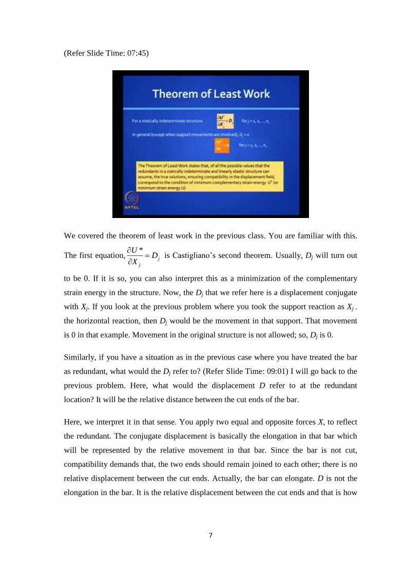
We covered the theorem of least work in the previous class. You are familiar with this.
The first equation,*
j
j
UD
X
is Castigliano’s second theorem. Usually, Dj will turn out
to be 0. If it is so, you can also interpret this as a minimization of the complementary
strain energy in the structure. Now, the Dj that we refer here is a displacement conjugate
with Xj. If you look at the previous problem where you took the support reaction as Xj -
the horizontal reaction, then Dj would be the movement in that support. That movement
is 0 in that example. Movement in the original structure is not allowed; so, Dj is 0.
Similarly, if you have a situation as in the previous case where you have treated the bar
as redundant, what would the Dj refer to? (Refer Slide Time: 09:01) I will go back to the
previous problem. Here, what would the displacement D refer to at the redundant
location? It will be the relative distance between the cut ends of the bar.
Here, we interpret it in that sense. You apply two equal and opposite forces X, to reflect
the redundant. The conjugate displacement is basically the elongation in that bar which
will be represented by the relative movement in that bar. Since the bar is not cut,
compatibility demands that, the two ends should remain joined to each other; there is no
relative displacement between the cut ends. Actually, the bar can elongate. D is not the
elongation in the bar. It is the relative displacement between the cut ends and that is how
8
it is reflected in Castigliano’s theorem. The interpretation of it is that, we are actually
minimizing the strain energy.
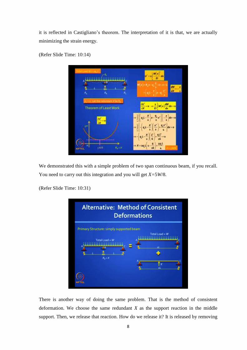
(Refer Slide Time: 10:14)
We demonstrated this with a simple problem of two span continuous beam, if you recall.
You need to carry out this integration and you will get X=5W/8.
(Refer Slide Time: 10:31)
There is another way of doing the same problem. That is the method of consistent
deformation. We choose the same redundant X as the support reaction in the middle
support. Then, we release that reaction. How do we release it? It is released by removing
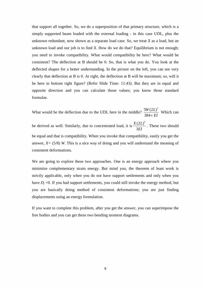
9
that support all together. So, we do a superposition of that primary structure, which is a
simply supported beam loaded with the external loading - in this case UDL, plus the
unknown redundant, now shown as a separate load case. So, we treat X as a load, but an
unknown load and our job is to find X. How do we do that? Equilibrium is not enough;
you need to invoke compatibility. What would compatibility be here? What would be
consistent? The deflection at B should be 0. So, that is what you do. You look at the
deflected shapes for a better understanding. In the picture on the left, you can see very
clearly that deflection at B is 0. At right, the deflection at B will be maximum; so, will it
be here in bottom right figure? (Refer Slide Time: 11:43). But they are in equal and
opposite direction and you can calculate those values; you know those standard
formulae.
What would be the deflection due to the UDL here in the middle? 35 (2 )
384
W L
EI Which can
be derived as well. Similarly, due to concentrated load, it is3(2 )
3
X L
EI. These two should
be equal and that is compatibility. When you invoke that compatibility, easily you get the
answer, X= (5/8) W. This is a nice way of doing and you will understand the meaning of
consistent deformations.
We are going to explore these two approaches. One is an energy approach where you
minimize complementary strain energy. But mind you, the theorem of least work is
strictly applicable, only when you do not have support settlements and only when you
have Dj =0. If you had support settlements, you could still invoke the energy method, but
you are basically doing method of consistent deformations; you are just finding
displacements using an energy formulation.
If you want to complete this problem, after you get the answer, you can superimpose the
free bodies and you can get these two bending moment diagrams.
10
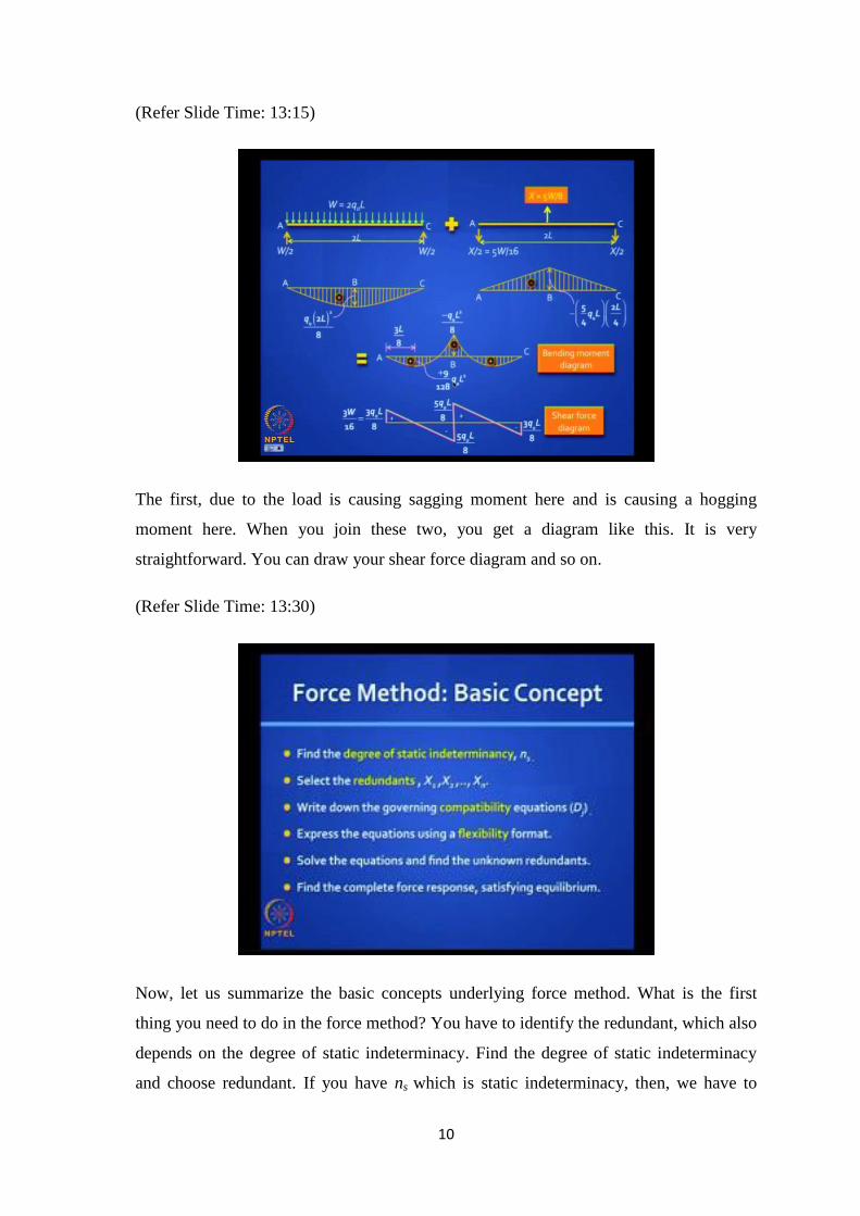
(Refer Slide Time: 13:15)
The first, due to the load is causing sagging moment here and is causing a hogging
moment here. When you join these two, you get a diagram like this. It is very
straightforward. You can draw your shear force diagram and so on.
(Refer Slide Time: 13:30)
Now, let us summarize the basic concepts underlying force method. What is the first
thing you need to do in the force method? You have to identify the redundant, which also
depends on the degree of static indeterminacy. Find the degree of static indeterminacy
and choose redundant. If you have ns which is static indeterminacy, then, we have to
11
choose as many redundants as the indeterminacy demands. Once you have chosen the
redundants, you have also chosen the primary structure, where those values of X are 0,
where you release such constraints.
Then, on those primary structures, what should you do? You first apply the external
loading.
Then you apply the redundants one at a time, if you wish and write down the governing
compatibility equations. Wherever you have made those releases, write down those
expressions. Usually, D1, D2, D3, D4, at those redundant locations will be 0, but there are
some exceptions. Where they are 0, you have a choice of invoking the theorem of least
work, but otherwise, we have to actually calculate.
Let us say, the support settles or moves horizontally. Then Dj is equal to that movement.
Express the equations using a flexibility format. Which equations? The compatibility
equations; you have choice here. Then, you solve these simultaneous equations and find
X1 to Xn. Once you have found X1 to Xn, you draw the free body; you have got a statically
determinate system. You can analyze it, draw the shear force diagram, draw the bending
moment diagram or find the axial forces in the case of a truss. You could do it directly on
that overall free body. Alternatively, you could find out what is happening under the
action of each of those loading systems on the primary structure and superpose
everything.
So, you find the complete force response. It satisfies the equilibrium, but more important
is that, it also satisfies compatibility.
12
(Refer Slide Time: 15:58)
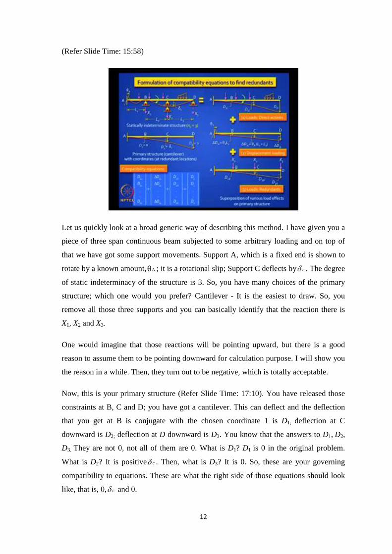
Let us quickly look at a broad generic way of describing this method. I have given you a
piece of three span continuous beam subjected to some arbitrary loading and on top of
that we have got some support movements. Support A, which is a fixed end is shown to
rotate by a known amount, A ; it is a rotational slip; Support C deflects by c . The degree
of static indeterminacy of the structure is 3. So, you have many choices of the primary
structure; which one would you prefer? Cantilever - It is the easiest to draw. So, you
remove all those three supports and you can basically identify that the reaction there is
X1, X2 and X3.
One would imagine that those reactions will be pointing upward, but there is a good
reason to assume them to be pointing downward for calculation purpose. I will show you
the reason in a while. Then, they turn out to be negative, which is totally acceptable.
Now, this is your primary structure (Refer Slide Time: 17:10). You have released those
constraints at B, C and D; you have got a cantilever. This can deflect and the deflection
that you get at B is conjugate with the chosen coordinate 1 is D1; deflection at C
downward is D2; deflection at D downward is D3. You know that the answers to D1, D2,
D3. They are not 0, not all of them are 0. What is D1? D1 is 0 in the original problem.
What is D2? It is positive c . Then, what is D3? It is 0. So, these are your governing
compatibility to equations. These are what the right side of those equations should look
like, that is, 0, c and 0.
13
Now, you take the primary structure and do a series of superposition. Please note that
you have two loads here. One is called direct loading; the external loads are directly
caused by those arrow marks that you see there. Some are forces and some are moments.
It is a concentrated moment shown there. You also have another kind of loading here.
What is that loading called?
(Refer Slide Time: 18:32)
Yes, that is called indirect loading, in this case, by support settlements. These two, you
should be able to put on your primary structure.
Loading - the direct forces are pretty easy to do. You can analyze this, can’t you? You
have to find the deflections D1L, D2L, D3L, the L stands for the loading - external loading.
At those locations 1, 2, 3, where the redundants operate, you must able to find D1L, D2L
and D3L. You know enough techniques of finding deflection; any method you can use;
we will use the unit load method because it will help us generate the flexibility matrix
very easily, in a generic fashion.
Then you take the same beam and now you apply support settlements. What will it look
like?
It is a rigid body moment. Of the two support settlements, support movements shown in
the original figure, c is accounted for on the right hand side of the equation. Do you
understand? c Is occurring at a redundant coordinate, but A is not at a redundant
coordinate; it is at a non-redundant coordinate - which you apply as a load, as an external
indirect loading on the primary structure. If you will allow that cantilever beam to rotate
by A , it will undergo a rigid body rotation. We are assuming very small deformations;
so, ASin and ATan are equal to A . So, can we write down those additional
movements at 1, 2 and 3 as shown here? (Refer Slide Time: 20:18) This is easy to
understand; A ×L1 is movement here (Refer Slide Time: 20:21), and so on and so forth.
Can we work them out? So, you have got all the movements caused by the external
loading on the primary structure.
14
(Refer Slide Time: 20:33)
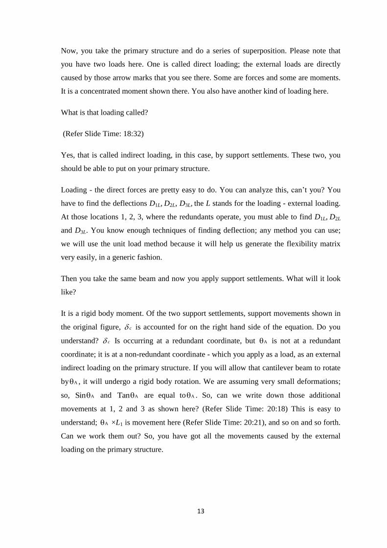
Now, you apply the redundants. Let us put them all together, in the beginning. You
apply X1, X2 and X3 and let us see the deflections that you get at 1, 2 and 3 are D1X, D2X
and D3X. Now, you are in a position to write the equations of compatibility. They will
look like this.
In general, you may have n locations, n displacements and n degree of static
indeterminacy. So, what have we written here? The first vector, first column on the left
side, it is the deflections that you get by the direct forces on the primary structure, which
is what we showed here (Refer Slide Time: 21:17). Next are the additional deflections
which you get in case you have indirect loading at non-redundant locations. If you have
displacements at redundant locations, they get covered on the right hand side here (Refer
Slide Time: 21:35).
Then, we are putting together all the deflections caused by the redundants on the primary
structure. You see how your learning has progressed. You first studied force response in
statically determinate structures; then you studied displacement response in statically
determinate structures and you need that understanding to write these expressions in the
compatibility equations, because you are still dealing with a statically determinate
primary structure.
15
(Refer Slide Time: 22:05)
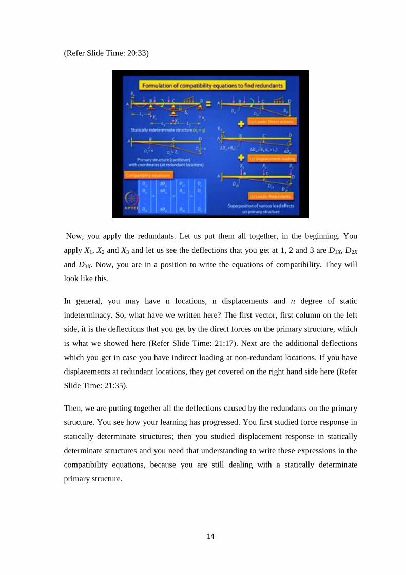
Now, you will find it convenient to apply one load at a time, according to the unit load
method. You are familiar with the definition of flexibility. I have shown here three
diagrams, three cantilever beams; they are identical beams, but I apply X1=1, X2=1, X3
=1; not all at the same time, but separately.
The definition of flexibility coefficient is that, the deflection here, caused by X1 = 1 is
called equal to f11, this is f21 and this is f31; this caused by X2 =1 is f12, f22 and f32 and so on
and so forth. So, this is a physical meaning and you will find that these flexibility
coefficients are properties of the structure; they do not depend on any loading. How do
you find these values? By, unit load method.
You can generate a nice formula, that is1
( ) ( )j km x m x dxEI . This is unit load method.
You can do that and write it in this format (Refer Slide Time: 23:20). So, all the
deflections caused by all the redundants put together can be written like this: D1X is
f11×X1 plus f12×X2, f1n×Xn etc. Similarly, for D2X, and so on. I can write that over all set of
equations. Also, I get the deflections caused by the load using the unit load method. So,
the beauty is - whatever unit bending moment diagram I drew for this and this and this
(Refer Slide Time: 23:54), come in handy when I find these deflections; because if I
want to find D1L, I need to apply a unit load here (Refer Slide Time: 24:04). Bending
moment diagram caused by this is called m1 and so on and so forth. Those moment
diagrams come in here.
16
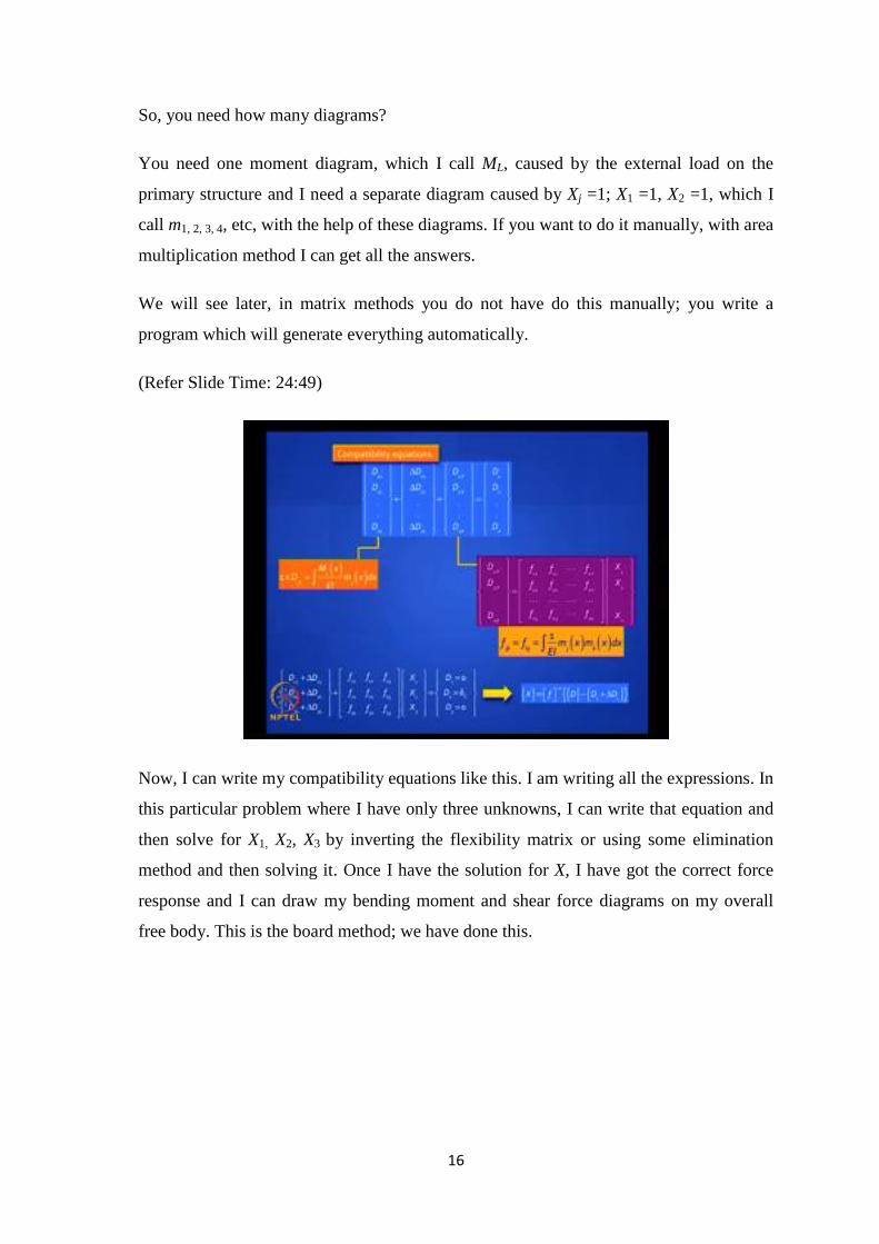
So, you need how many diagrams?
You need one moment diagram, which I call ML, caused by the external load on the
primary structure and I need a separate diagram caused by Xj =1; X1 =1, X2 =1, which I
call m1, 2, 3, 4, etc, with the help of these diagrams. If you want to do it manually, with area
multiplication method I can get all the answers.
We will see later, in matrix methods you do not have do this manually; you write a
program which will generate everything automatically.
(Refer Slide Time: 24:49)
Now, I can write my compatibility equations like this. I am writing all the expressions. In
this particular problem where I have only three unknowns, I can write that equation and
then solve for X1, X2, X3 by inverting the flexibility matrix or using some elimination
method and then solving it. Once I have the solution for X, I have got the correct force
response and I can draw my bending moment and shear force diagrams on my overall
free body. This is the board method; we have done this.
17
(Refer Slide Time: 25:26)
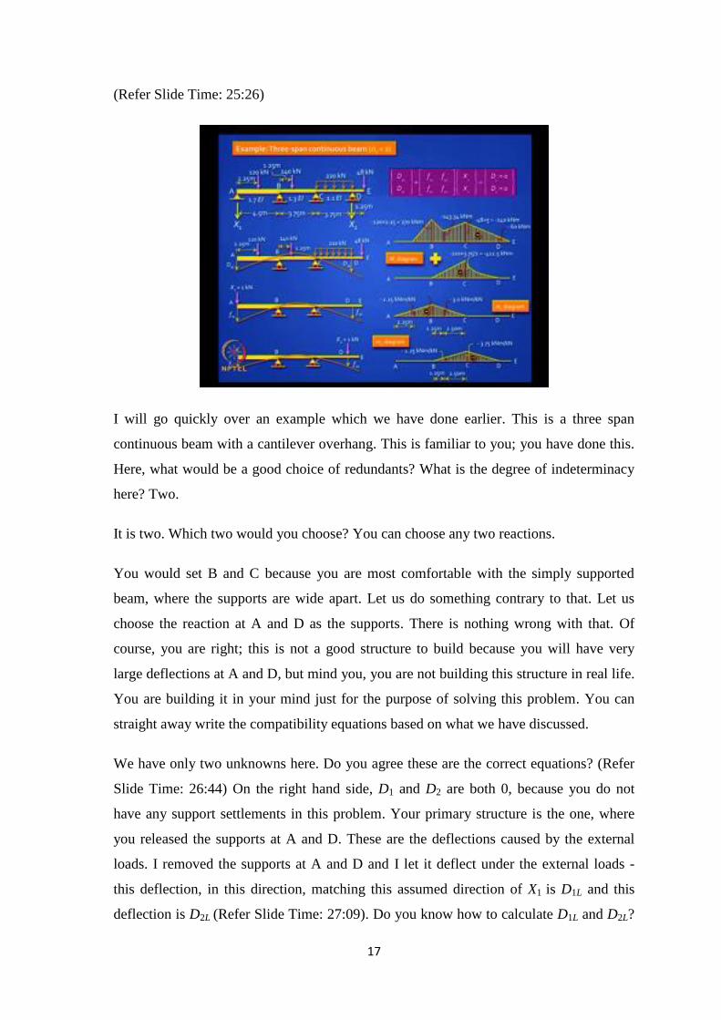
I will go quickly over an example which we have done earlier. This is a three span
continuous beam with a cantilever overhang. This is familiar to you; you have done this.
Here, what would be a good choice of redundants? What is the degree of indeterminacy
here? Two.
It is two. Which two would you choose? You can choose any two reactions.
You would set B and C because you are most comfortable with the simply supported
beam, where the supports are wide apart. Let us do something contrary to that. Let us
choose the reaction at A and D as the supports. There is nothing wrong with that. Of
course, you are right; this is not a good structure to build because you will have very
large deflections at A and D, but mind you, you are not building this structure in real life.
You are building it in your mind just for the purpose of solving this problem. You can
straight away write the compatibility equations based on what we have discussed.
We have only two unknowns here. Do you agree these are the correct equations? (Refer
Slide Time: 26:44) On the right hand side, D1 and D2 are both 0, because you do not
have any support settlements in this problem. Your primary structure is the one, where
you released the supports at A and D. These are the deflections caused by the external
loads. I removed the supports at A and D and I let it deflect under the external loads -
this deflection, in this direction, matching this assumed direction of X1 is D1L and this
deflection is D2L (Refer Slide Time: 27:09). Do you know how to calculate D1L and D2L?
18
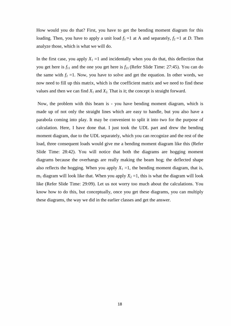
How would you do that? First, you have to get the bending moment diagram for this
loading. Then, you have to apply a unit load f1 =1 at A and separately, f2 =1 at D. Then
analyze those, which is what we will do.
In the first case, you apply X1 =1 and incidentally when you do that, this deflection that
you get here is f11 and the one you get here is f21 (Refer Slide Time: 27:45). You can do
the same with f2 =1. Now, you have to solve and get the equation. In other words, we
now need to fill up this matrix, which is the coefficient matrix and we need to find these
values and then we can find X1 and X2. That is it; the concept is straight forward.
Now, the problem with this beam is - you have bending moment diagram, which is
made up of not only the straight lines which are easy to handle, but you also have a
parabola coming into play. It may be convenient to split it into two for the purpose of
calculation. Here, I have done that. I just took the UDL part and drew the bending
moment diagram, due to the UDL separately, which you can recognize and the rest of the
load, three consequent loads would give me a bending moment diagram like this (Refer
Slide Time: 28:42). You will notice that both the diagrams are hogging moment
diagrams because the overhangs are really making the beam hog; the deflected shape
also reflects the hogging. When you apply X1 =1, the bending moment diagram, that is,
m1 diagram will look like that. When you apply X2 =1, this is what the diagram will look
like (Refer Slide Time: 29:09). Let us not worry too much about the calculations. You
know how to do this, but conceptually, once you get these diagrams, you can multiply
these diagrams, the way we did in the earlier classes and get the answer.
19
(Refer Slide Time: 29:23)
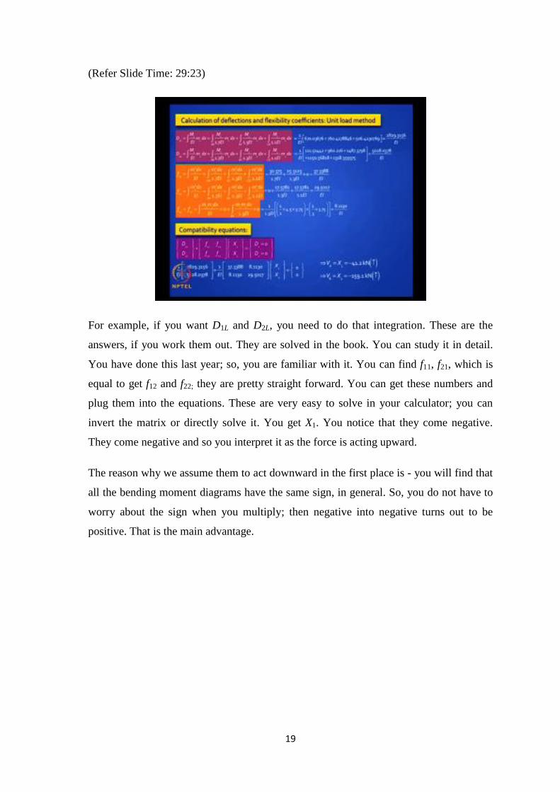
For example, if you want D1L and D2L, you need to do that integration. These are the
answers, if you work them out. They are solved in the book. You can study it in detail.
You have done this last year; so, you are familiar with it. You can find f11, f21, which is
equal to get f12 and f22; they are pretty straight forward. You can get these numbers and
plug them into the equations. These are very easy to solve in your calculator; you can
invert the matrix or directly solve it. You get X1. You notice that they come negative.
They come negative and so you interpret it as the force is acting upward.
The reason why we assume them to act downward in the first place is - you will find that
all the bending moment diagrams have the same sign, in general. So, you do not have to
worry about the sign when you multiply; then negative into negative turns out to be
positive. That is the main advantage.
20
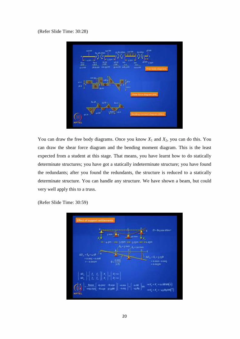
(Refer Slide Time: 30:28)
You can draw the free body diagrams. Once you know X1 and X2, you can do this. You
can draw the shear force diagram and the bending moment diagram. This is the least
expected from a student at this stage. That means, you have learnt how to do statically
determinate structures; you have got a statically indeterminate structure; you have found
the redundants; after you found the redundants, the structure is reduced to a statically
determinate structure. You can handle any structure. We have shown a beam, but could
very well apply this to a truss.
(Refer Slide Time: 30:59)
21
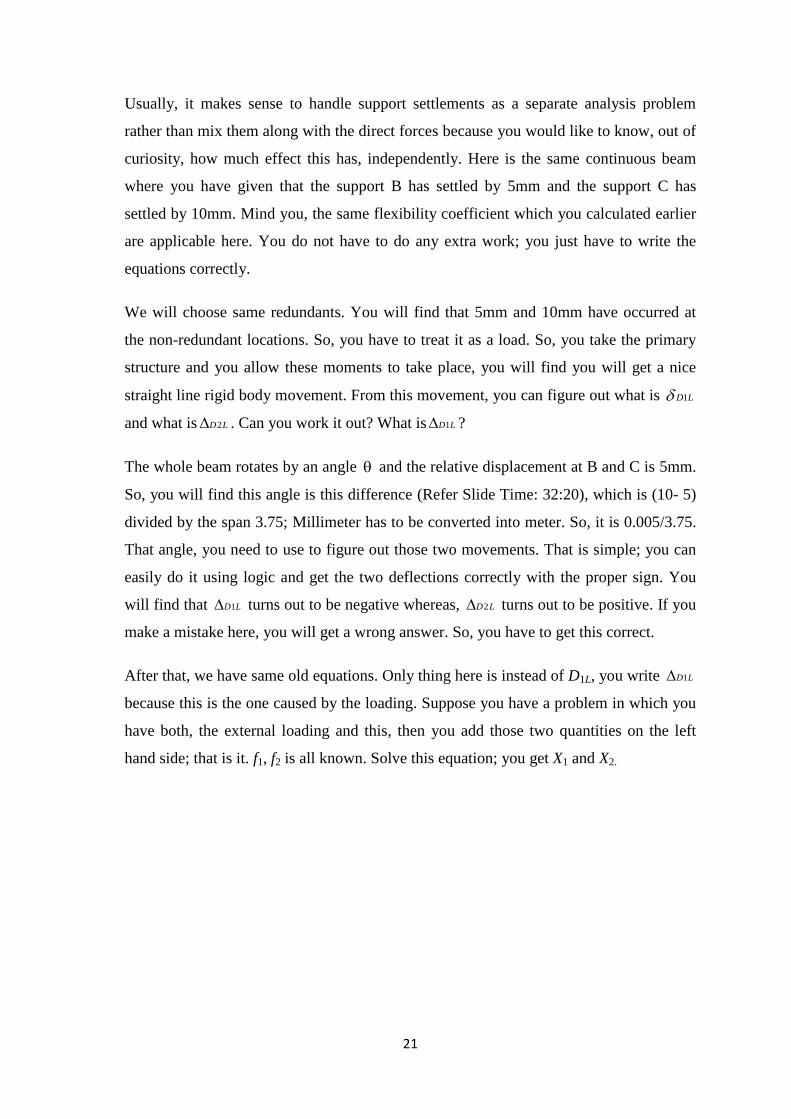
Usually, it makes sense to handle support settlements as a separate analysis problem
rather than mix them along with the direct forces because you would like to know, out of
curiosity, how much effect this has, independently. Here is the same continuous beam
where you have given that the support B has settled by 5mm and the support C has
settled by 10mm. Mind you, the same flexibility coefficient which you calculated earlier
are applicable here. You do not have to do any extra work; you just have to write the
equations correctly.
We will choose same redundants. You will find that 5mm and 10mm have occurred at
the non-redundant locations. So, you have to treat it as a load. So, you take the primary
structure and you allow these moments to take place, you will find you will get a nice
straight line rigid body movement. From this movement, you can figure out what is 1D L
and what is 2D L . Can you work it out? What is 1D L ?
The whole beam rotates by an angle and the relative displacement at B and C is 5mm.
So, you will find this angle is this difference (Refer Slide Time: 32:20), which is (10- 5)
divided by the span 3.75; Millimeter has to be converted into meter. So, it is 0.005/3.75.
That angle, you need to use to figure out those two movements. That is simple; you can
easily do it using logic and get the two deflections correctly with the proper sign. You
will find that 1D L turns out to be negative whereas, 2D L turns out to be positive. If you
make a mistake here, you will get a wrong answer. So, you have to get this correct.
After that, we have same old equations. Only thing here is instead of D1L, you write 1D L
because this is the one caused by the loading. Suppose you have a problem in which you
have both, the external loading and this, then you add those two quantities on the left
hand side; that is it. f1, f2 is all known. Solve this equation; you get X1 and X2.
22
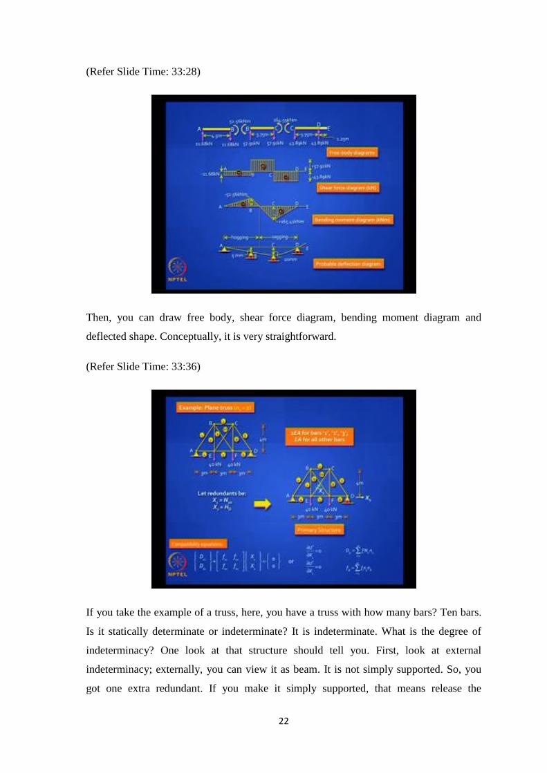
(Refer Slide Time: 33:28)
Then, you can draw free body, shear force diagram, bending moment diagram and
deflected shape. Conceptually, it is very straightforward.
(Refer Slide Time: 33:36)
If you take the example of a truss, here, you have a truss with how many bars? Ten bars.
Is it statically determinate or indeterminate? It is indeterminate. What is the degree of
indeterminacy? One look at that structure should tell you. First, look at external
indeterminacy; externally, you can view it as beam. It is not simply supported. So, you
got one extra redundant. If you make it simply supported, that means release the
23
horizontal reaction which is that one external indeterminacy, and internally, you got an
extra diagonal. You can choose. That is what you can do.
You can choose one of those diagonal forces as one redundant and a horizontal reaction;
may be a reaction at D as another redundant. So, your primary structure will look like
this. You made a roller support at D and you cut the bar – 10 in this case. The forces, if
you want to insert them, will be X1, which is the tension in that bar 10, which you do not
know, and the horizontal reaction, we are calling it as X2. Now, write down the
compatibility equation. They take the same format; it is very easy to write them down.
On the right hand side, D1 and D2 are 0. When you say D1 is 0 you are actually making a
statement that the relative displacement between the cut ends is 0; the bar should never
have been cut in the first place. We are not saying that this point is not going to move; it
will move when the bar elongates or contracts. But we are saying the relative moment is
not there. So, those double arrows pointing towards each other refer to relative
movement, when you interpret from a displacement perspective.
Physically, it is a little troublesome, because if they really approach each other, they will
penetrate each other or overlap each other. That is something that you worry about in
your mind. They can separate out or they can penetrate. You can also use the strain
energy formulation and solve the same equations; they mean the same. How do you
calculate the displacements? You can use a unit load method; I hope you are familiar
with this. Apply X1 =1, get those forces; apply X2 =1, get those forces and so on.
24
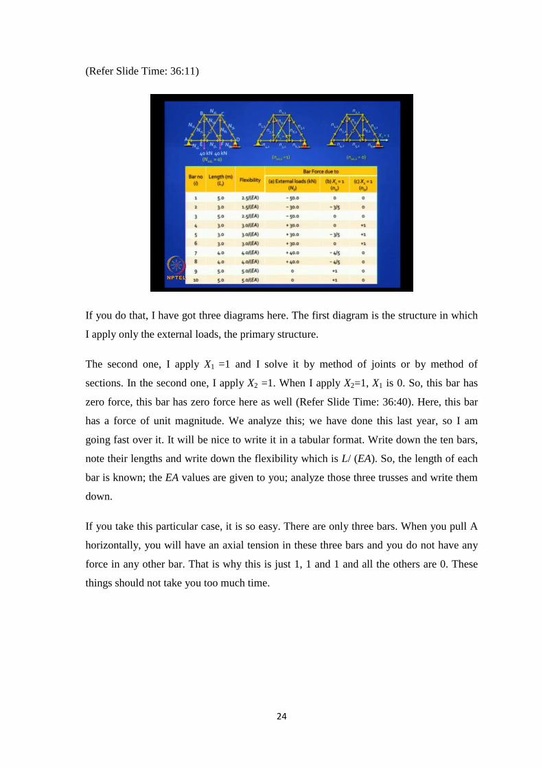
(Refer Slide Time: 36:11)
If you do that, I have got three diagrams here. The first diagram is the structure in which
I apply only the external loads, the primary structure.
The second one, I apply X1 =1 and I solve it by method of joints or by method of
sections. In the second one, I apply X2 =1. When I apply X2=1, X1 is 0. So, this bar has
zero force, this bar has zero force here as well (Refer Slide Time: 36:40). Here, this bar
has a force of unit magnitude. We analyze this; we have done this last year, so I am
going fast over it. It will be nice to write it in a tabular format. Write down the ten bars,
note their lengths and write down the flexibility which is L/ (EA). So, the length of each
bar is known; the EA values are given to you; analyze those three trusses and write them
down.
If you take this particular case, it is so easy. There are only three bars. When you pull A
horizontally, you will have an axial tension in these three bars and you do not have any
force in any other bar. That is why this is just 1, 1 and 1 and all the others are 0. These
things should not take you too much time.
25
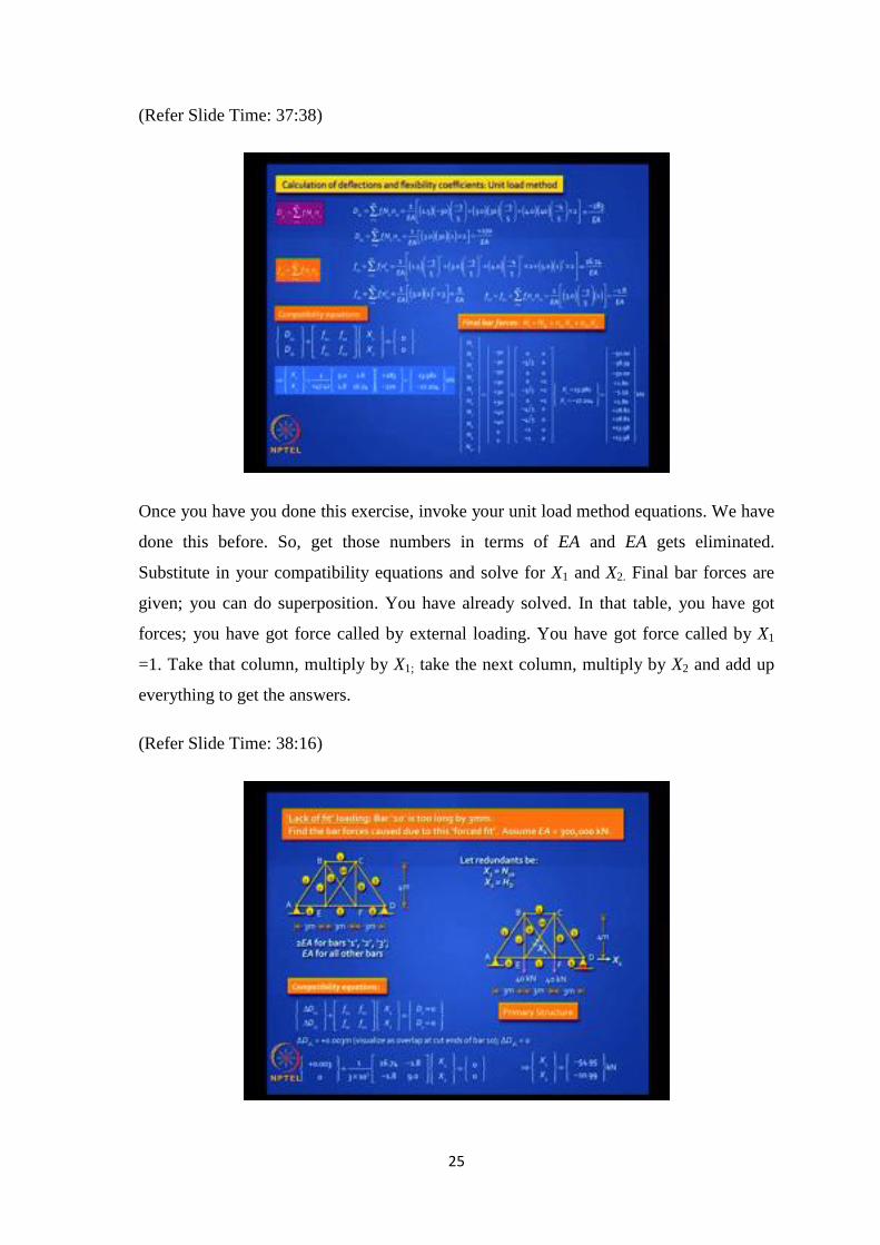
(Refer Slide Time: 37:38)
Once you have you done this exercise, invoke your unit load method equations. We have
done this before. So, get those numbers in terms of EA and EA gets eliminated.
Substitute in your compatibility equations and solve for X1 and X2. Final bar forces are
given; you can do superposition. You have already solved. In that table, you have got
forces; you have got force called by external loading. You have got force called by X1
=1. Take that column, multiply by X1; take the next column, multiply by X2 and add up
everything to get the answers.
(Refer Slide Time: 38:16)
26
It is interesting to note that some of those bar forces will be positive and some will be
negative; you must be able to judge correctly. For example, in that particular loading,
you would expect the bottom chord to be in tension and the top chords to be in
compression, in the verticals and diagonals appropriately. You should figure it out.
Let us take a displacement loading problem. Let us say, you have a lack of fit problem,
bar 10 is too long by 3 mm. When it came to the side, that bar was too long; so it had to
be force fitted; that means, it had to be hammered into place. Because the structure is
over rigid, all the other bars will resist this fixing. Had it been just rigid, they will move
and accommodate this movement. You have a problem. You are forcing that bar to be
fitted. First of all, can you tell me what will be the force in that bar? It will be
compression, because it was too long and it will not be allowed to get that length of 3
mm; the final excess length may be 2 mm or 1 mm. It depends on the relative stiffness of
all those bars. Because of this, the other bars will also be stressed. So, you have a self-
equilibrating system.
How do you solve this problem? (Refer Slide Time: 39:49) Let us take the same
redundants, as we have identified earlier. Now, the compatibility equation will look like
this. This is because now you have a displacement loading.
How will you get 1D L and 2D L ? This is not as easy as the previous problem where you
had the rigid body movement in your beam.
How will you find this out? What is 1D L and 2D L ? What does this physically mean?
If you take the primary structure where you have the roller support at D and the bar 10 is
cut and when you allow this bar 10 to be too long by 3 mm, will you have any forces in
the system? No, because it is just rigid and is statically determinate. You will have no
forces.
Can you write down 1D L and 2D L ? What will 1D L be? It will be 3 mm; it is free to take
whatever length you want it to take.
Will it be positive 3 mm or negative 3 mm?
It will be positive 3 millimeter. It is too long; so, it will be plus 3 mm.
27
What is 2D L ? 2D L Is 0. Now, this 3 mm, you should write in consistent units. So, it is
0.003 meters. If it is too long, you should visualize this as overlap of those two bars by 3
mm.
That is all you have to do. You have already got the flexibility matrix in the previous
example. So, you just have to plug in these values.
Sir, why are we not taking D1 as 3 mm?
This is a good question. What is D1? D1 is the final displacement in the original real
structure, not the primary structure. When you identified X1 as the axial force in that
member and the primary structure was a structure in which you cut that member, D1 is
nothing but the relative displacement between the cut ends.
What is the relative displacement between the cut ends? It is 0. These are the typical
mistakes that students make. D1 is always 0, because it is the relative displacement
between the cut ends. You had no business to cut that bar. 3 mm is the elongation in that
bar in a statically determinate system, which is the relative distance between the cut ends
in the primary structure. When we are talking about the primary structure, you not
talking about the right hand side, you talking about the left hand side; because all these
quantities on this side of the compatibility equations, relate to primary structure. This is a
common mistake we tend to make.
D2 is always 0, so you do not have to worry. You already got the flexibility matrix, you
inverted it earlier and so it is very easy to solve and get X1 and X2.
Once you are familiar with the truss and its flexibility matrix, you can handle any
loading; you put 100 loads, you get hundred answers just by solving this matrix.
28
(Refer Slide Time: 43:57)
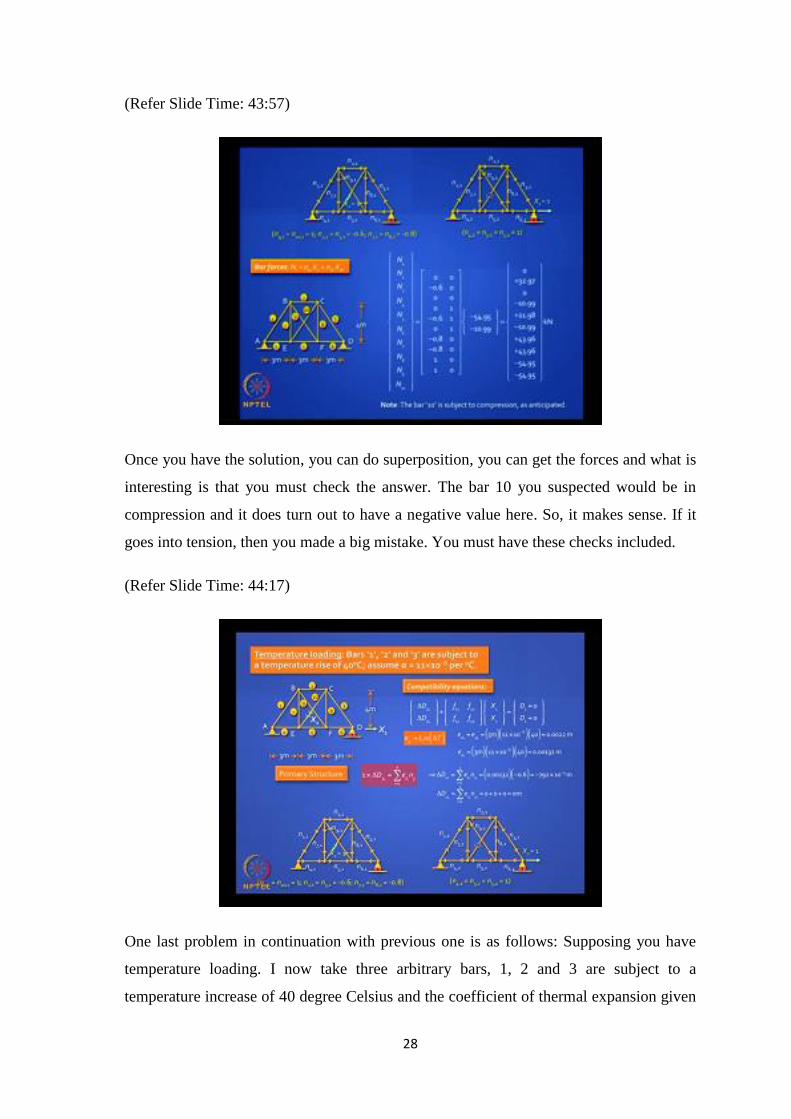
Once you have the solution, you can do superposition, you can get the forces and what is
interesting is that you must check the answer. The bar 10 you suspected would be in
compression and it does turn out to have a negative value here. So, it makes sense. If it
goes into tension, then you made a big mistake. You must have these checks included.
(Refer Slide Time: 44:17)
One last problem in continuation with previous one is as follows: Supposing you have
temperature loading. I now take three arbitrary bars, 1, 2 and 3 are subject to a
temperature increase of 40 degree Celsius and the coefficient of thermal expansion given
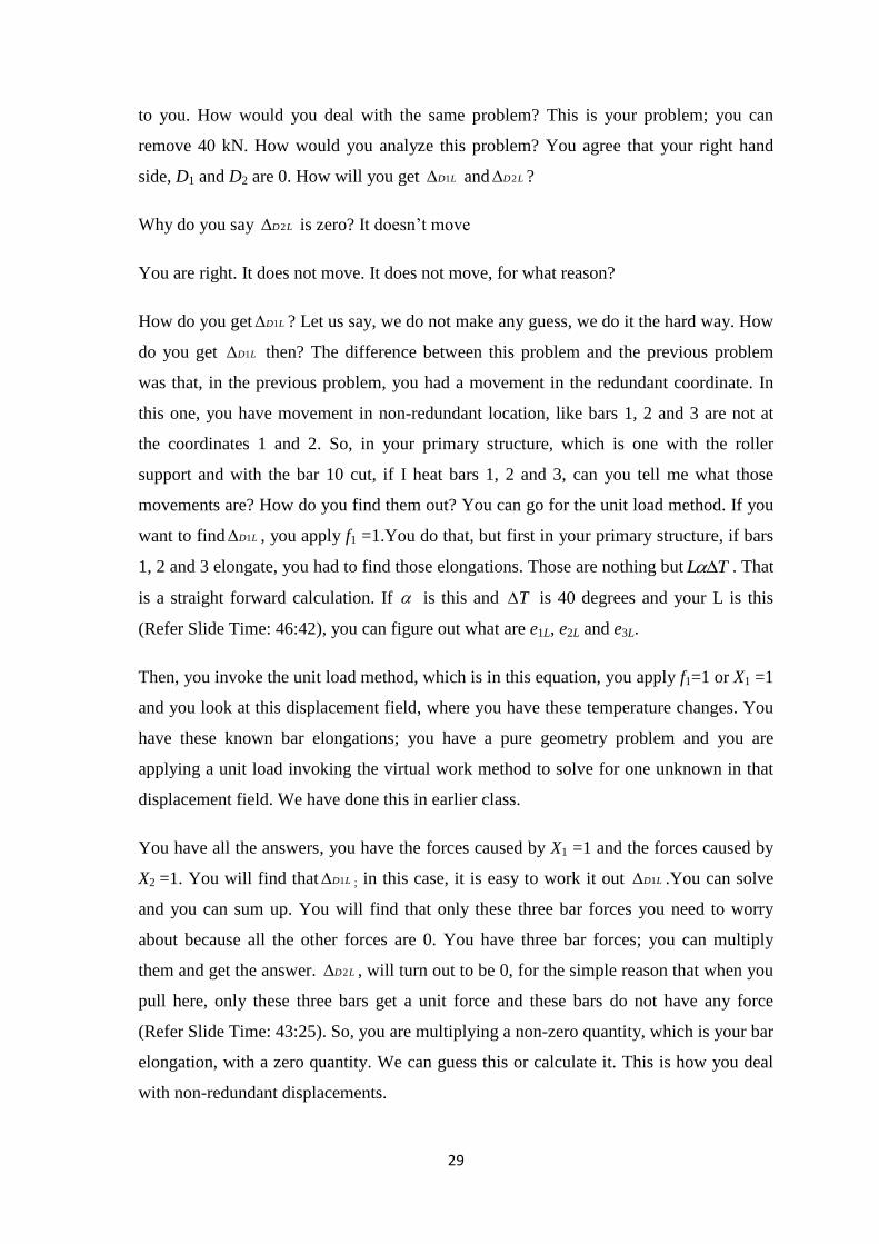
29
to you. How would you deal with the same problem? This is your problem; you can
remove 40 kN. How would you analyze this problem? You agree that your right hand
side, D1 and D2 are 0. How will you get 1D L and 2D L ?
Why do you say 2D L is zero? It doesn’t move
You are right. It does not move. It does not move, for what reason?
How do you get 1D L ? Let us say, we do not make any guess, we do it the hard way. How
do you get 1D L then? The difference between this problem and the previous problem
was that, in the previous problem, you had a movement in the redundant coordinate. In
this one, you have movement in non-redundant location, like bars 1, 2 and 3 are not at
the coordinates 1 and 2. So, in your primary structure, which is one with the roller
support and with the bar 10 cut, if I heat bars 1, 2 and 3, can you tell me what those
movements are? How do you find them out? You can go for the unit load method. If you
want to find 1D L , you apply f1 =1.You do that, but first in your primary structure, if bars
1, 2 and 3 elongate, you had to find those elongations. Those are nothing but L T . That
is a straight forward calculation. If is this and T is 40 degrees and your L is this
(Refer Slide Time: 46:42), you can figure out what are e1L, e2L and e3L.
Then, you invoke the unit load method, which is in this equation, you apply f1=1 or X1 =1
and you look at this displacement field, where you have these temperature changes. You
have these known bar elongations; you have a pure geometry problem and you are
applying a unit load invoking the virtual work method to solve for one unknown in that
displacement field. We have done this in earlier class.
You have all the answers, you have the forces caused by X1 =1 and the forces caused by
X2 =1. You will find that 1D L ; in this case, it is easy to work it out 1D L .You can solve
and you can sum up. You will find that only these three bar forces you need to worry
about because all the other forces are 0. You have three bar forces; you can multiply
them and get the answer. 2D L , will turn out to be 0, for the simple reason that when you
pull here, only these three bars get a unit force and these bars do not have any force
(Refer Slide Time: 43:25). So, you are multiplying a non-zero quantity, which is your bar
elongation, with a zero quantity. We can guess this or calculate it. This is how you deal
with non-redundant displacements.
30
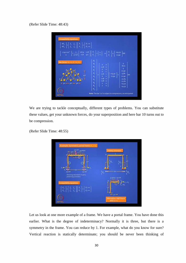
(Refer Slide Time: 48:43)
We are trying to tackle conceptually, different types of problems. You can substitute
these values, get your unknown forces, do your superposition and here bar 10 turns out to
be compression.
(Refer Slide Time: 48:55)
Let us look at one more example of a frame. We have a portal frame. You have done this
earlier. What is the degree of indeterminacy? Normally it is three, but there is a
symmetry in the frame. You can reduce by 1. For example, what do you know for sure?
Vertical reaction is statically determinate; you should be never been thinking of
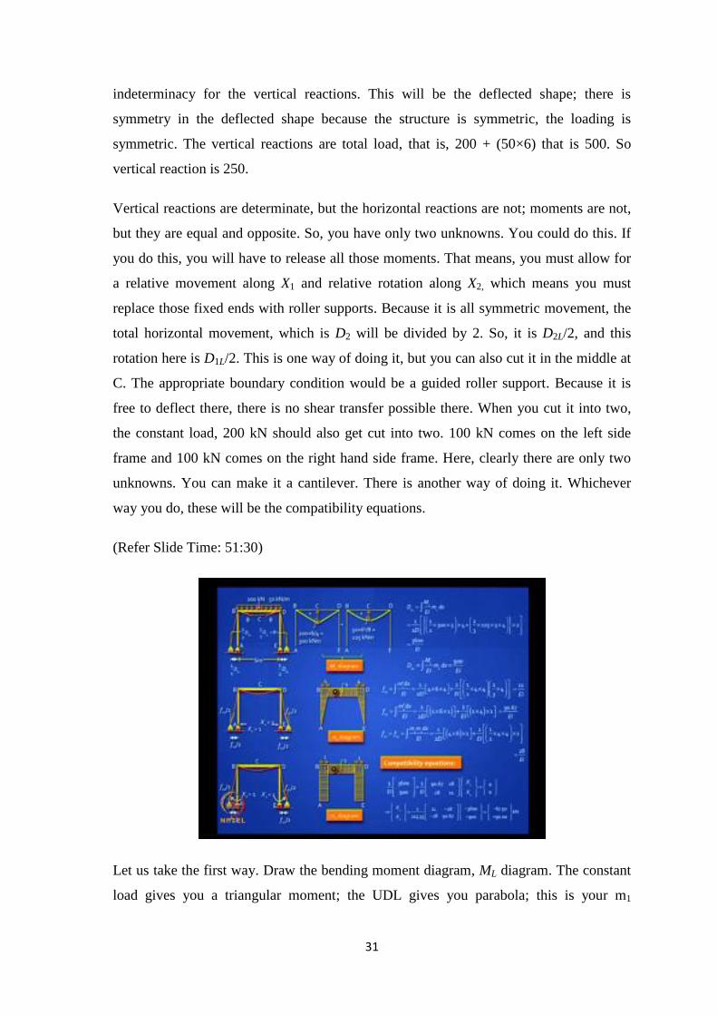
31
indeterminacy for the vertical reactions. This will be the deflected shape; there is
symmetry in the deflected shape because the structure is symmetric, the loading is
symmetric. The vertical reactions are total load, that is, 200 + (50×6) that is 500. So
vertical reaction is 250.
Vertical reactions are determinate, but the horizontal reactions are not; moments are not,
but they are equal and opposite. So, you have only two unknowns. You could do this. If
you do this, you will have to release all those moments. That means, you must allow for
a relative movement along X1 and relative rotation along X2, which means you must
replace those fixed ends with roller supports. Because it is all symmetric movement, the
total horizontal movement, which is D2 will be divided by 2. So, it is D2L/2, and this
rotation here is D1L/2. This is one way of doing it, but you can also cut it in the middle at
C. The appropriate boundary condition would be a guided roller support. Because it is
free to deflect there, there is no shear transfer possible there. When you cut it into two,
the constant load, 200 kN should also get cut into two. 100 kN comes on the left side
frame and 100 kN comes on the right hand side frame. Here, clearly there are only two
unknowns. You can make it a cantilever. There is another way of doing it. Whichever
way you do, these will be the compatibility equations.
(Refer Slide Time: 51:30)
Let us take the first way. Draw the bending moment diagram, ML diagram. The constant
load gives you a triangular moment; the UDL gives you parabola; this is your m1
32
diagram, when you apply X1 =1; this is m2 diagram, when you apply X2 =1. You do not
even need to mark those deflections; they are just to help you understand; you can
blindly go ahead and calculate D1L, D2L, f11, f22, f12. Once you have unit load, it is pretty
easy to calculate. We have done this earlier. So, the method is straightforward.
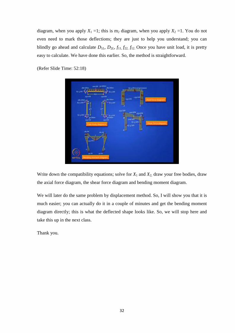
(Refer Slide Time: 52:18)
Write down the compatibility equations; solve for X1 and X2; draw your free bodies, draw
the axial force diagram, the shear force diagram and bending moment diagram.
We will later do the same problem by displacement method. So, I will show you that it is
much easier; you can actually do it in a couple of minutes and get the bending moment
diagram directly; this is what the deflected shape looks like. So, we will stop here and
take this up in the next class.
Thank you.

33
KEYWORDS
Indeterminate
Force Method
Flexibility matrix
Compatability
Unit load method