Embed Size (px)
Citation preview
8/8/2019 Advanced STP
http://slidepdf.com/reader/full/advanced-stp 1/7
Networking TechnologyNET 272 Lab Exercise
Advanced STP PVST+, RSTP, MST
Conducted on 9/16By: Chris Ortiz
8/8/2019 Advanced STP
http://slidepdf.com/reader/full/advanced-stp 2/7
Objective
The purpose of this lab is to configure and monitor STP features within a Cisco IOS environmentof switches.
Part 1: Connect Switched Network and Configure VLAN Operation
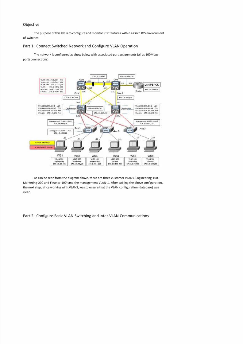
The network is configured as show below with associated port assignments (all at 100Mbps
ports connections):
As can be seen from the diagram above, there are three customer VLANs (Engineering-100,
Marketing-200 and Finance-100) and the management VLAN-1. After cabling the above configuration,
th t t i ki ith VLANS t th t th VLAN fi ti (d t b )
8/8/2019 Advanced STP
http://slidepdf.com/reader/full/advanced-stp 3/7
IP addressing was completed on physical, logical and loopback interfaces as shown in the earlier
network diagram. Additionally, we configured each access switch with a default gateway which
pointed to the SVI on the distribution switch. All access switches were also configured as VTP clients,
allowing the distribution switches serving as VTP clients.
Acc3(config)#vtp mode client Sets VTP to client mode
Acc3(config)#vtp domain team1Changing VTP domain name from cisco to team1 Sets the VTP domain name (must match)
Acc3(config)#vtp password cisco Sets the VTP domain password (must match)
Acc3(config-if)#spanning-tree portfast Forces an access port to immediately
transition to forwarding state
Access Switch ports were hard-coded to become access ports and put in the VLAN respective
to its connected host.
The distribution switches in the network were also configured with default gateways and
configured as VTP servers. We manually configure our trunking ports to trunk mode:
Acc3(config-if)#switchport trunk encapsulation dot1qAcc3(config-if)#switchport mode trunk
VLAN access could further be configured to restrict specific VLAN traffic:
Acc3(config-if)#switchport trunk allowed vlan 1,100,200,300
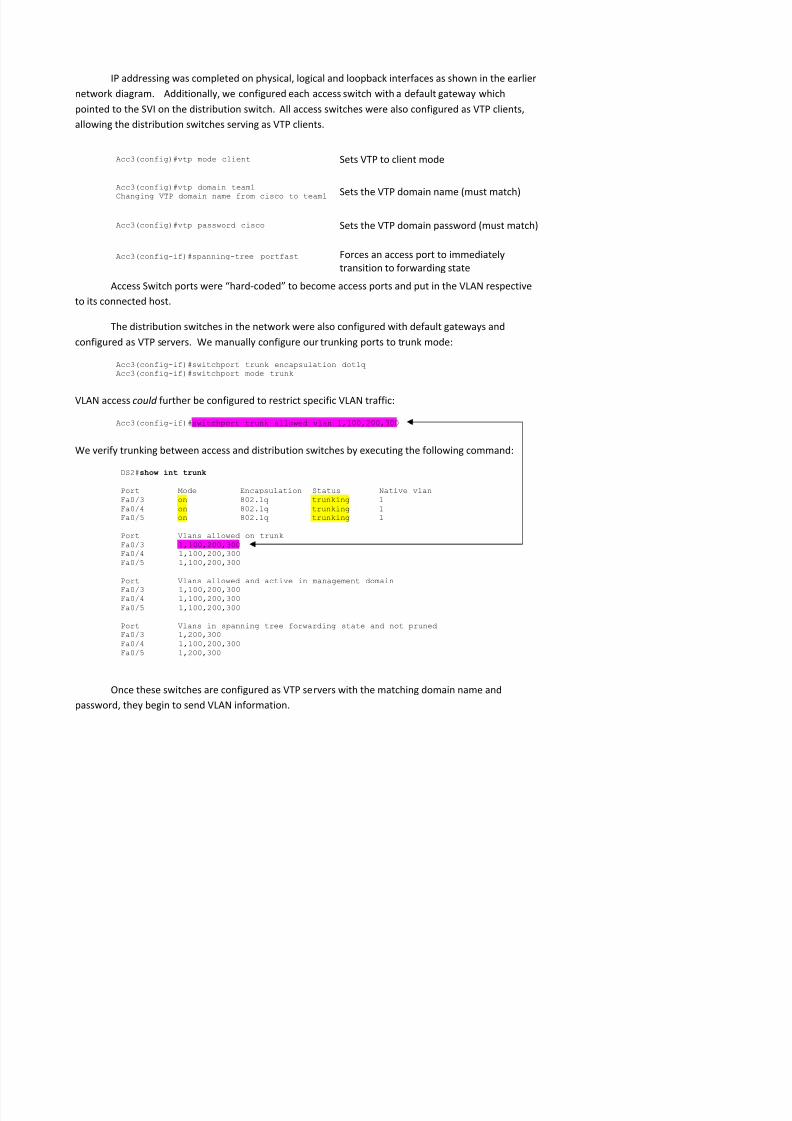
We verify trunking between access and distribution switches by executing the following command:
DS2#show int trunk
Port Mode Encapsulation Status Native vlanFa0/3 on 802.1q trunking 1Fa0/4 on 802.1q trunking 1Fa0/5 on 802.1q trunking 1
Port Vlans allowed on trunkFa0/3 1,100,200,300Fa0/4 1,100,200,300Fa0/5 1,100,200,300
Port Vlans allowed and active in management domainFa0/3 1,100,200,300Fa0/4 1,100,200,300Fa0/5 1 100 200 300
8/8/2019 Advanced STP
http://slidepdf.com/reader/full/advanced-stp 4/7
Acc3(config)#vtp mode server Sets VTP to server mode
Acc3(config)#vtp domain team1Changing VTP domain name from cisco to team1 Sets the VTP domain name (must match)
Acc3(config)#vtp password cisco Sets the VTP domain password (must match)
Finally, the VLANs are created on the distribution switches (VTP servers) and the VLAN
information is then propagated to the client (and server or transparent) switches participating in this
VTP instance.
We know that the only way for a host in one VLAN to pass traffic to a host in a different VLAN is
to introduce routing either statically or dynamically. In order to first tell a multi-layer switch that it
will perform as a layer 3 device, the following command must be issued:
DS2(config)#ip routing
At this point, devices within the same VLAN are able to communication with each other. We
verify this with ping commands.
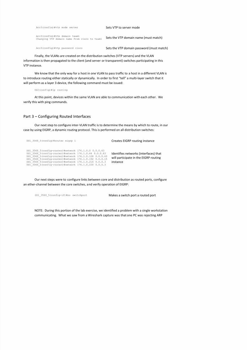
Part 3 Configuring Routed Interfaces
Our next step to configure inter-VLAN traffic is to determine the means by which to route, in our
case by using EIGRP, a dynamic routing protocol. This is performed on all distribution switches:
DS1_3560_5(config)#router eigrp 1 Creates EIGRP routing instance
DS1_3560_5(config-router)#network 176.1.0.0 0.0.0.63DS1_3560_5(config-router)#network 176.1.0.64 0.0.0.63DS1_3560_5(config-router)#network 176.1.0.128 0.0.0.63DS1_3560_5(config-router)#network 176.1.0.192 0.0.0.15DS1_3560_5(config-router)#network 176.1.0.216 0.0.0.3DS1_3560_5(config-router)#network 176.1.0.220 0.0.0.3
Identifies networks (interfaces) that
will participate in the EIGRP routing
instance
Our next steps were to configure links between core and distribution as routed ports, configure
an ether-channel between the core switches, and verify operation of EIGRP:
8/8/2019 Advanced STP
http://slidepdf.com/reader/full/advanced-stp 5/7
requests. We finally rebooted the machine to resolve the issue, which led us to believe that the
workstation was possibly latched onto a previously configured IP address and network.
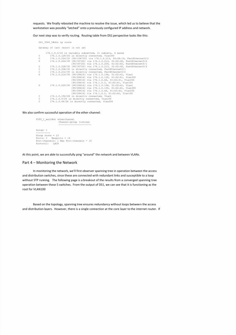
Our next step was to verify routing. Routing table from DS1 perspective looks like this:
DS1_3560_5#sho ip route
Gateway of last resort is not set
176.1.0.0/16 is variably subnetted, 11 subnets, 4 masksC 176.1.0.128/26 is directly connected, Vlan300D 176.1.0.254/32 [90/158720] via 176.1.0.213, 00:58:19, FastEthernet0/2D 176.1.0.224/30 [90/30720] via 176.1.0.213, 01:02:40, FastEthernet0/2
[90/30720] via 176.1.0.209, 01:02:40, FastEthernet0/1D 176.1.0.228/30 [90/30720] via 176.1.0.213, 01:02:40, FastEthernet0/2C 176.1.0.208/30 is directly connected, FastEthernet0/1C 176.1.0.212/30 is directly connected, FastEthernet0/2D 176.1.0.216/30 [90/28416] via 176.1.0.194, 01:02:41, Vlan1
[90/28416] via 176.1.0.130, 01:02:41, Vlan300[90/28416] via 176.1.0.66, 01:02:41, Vlan200[90/28416] via 176.1.0.2, 01:02:41, Vlan100
D 176.1.0.220/30 [90/28416] via 176.1.0.194, 01:02:41, Vlan1[90/28416] via 176.1.0.130, 01:02:41, Vlan300[90/28416] via 176.1.0.66, 01:02:42, Vlan200[90/28416] via 176.1.0.2, 01:02:42, Vlan100
C 176.1.0.192/28 is directly connected, Vlan1C 176.1.0.0/26 is directly connected, Vlan100C 176.1.0.64/26 is directly connected, Vlan200
We also confirm successful operation of the ether-channel:
6500_1_exit#sh etherchannelChannel-group listing:-----------------------
Group: 1----------Group state = L3Ports: 2 Maxports = 16Port-channels: 1 Max Port-channels = 16Protocol: LACP
At this point, we are able to successfully ping around the network and between VLANs.
Part 4 Monitoring the Network
In monitoring the network, well first observer spanning tree in operation between the access
and distribution switches, since these are connected with redundant links and susceptible to a loop
without STP running. The following page is a breakout of the results from a converged spanning tree

8/8/2019 Advanced STP
http://slidepdf.com/reader/full/advanced-stp 6/7
Core2 were to fail, access to the internet from this network would be unavailable, as well as access
from the internet to this network.

8/8/2019 Advanced STP
http://slidepdf.com/reader/full/advanced-stp 7/7


![STP Ozonation & Advanced Oxidation Process [AOP]](https://img.pdfslide.us/doc/110x75/58d1472a1a28ab455d8b65d5/stp-ozonation-advanced-oxidation-process-aop.jpg)