Embed Size (px)
Citation preview

1
Advanced Soft Switching Inverter for Reducing Switching and
Power Losses
Jason Lai
Virginia Polytechnic Institute and State University
June 10, 2010
This presentation does not contain any proprietary, confidential, or otherwise restricted information
Project ID: APE011

2
Outline
• Overview
• Objectives
• Milestones
• Approaches
• Accomplishments
• Future Work
• Summary

3
Overview
• Start – Sep 2007 • Finish – Sep 2010 • 75% Complete
• Barriers addressed– Inverter Cost– Inverter Weight and Volume– Inverter Thermal Management
• Target – Achieve efficiency >99% to allow
the use of silicon devices at 105°coolant operating condition
Timeline
Budget
Barriers
• National Institute of Standards and Technology – Modeling and Simulation
• Powerex – Soft switch module packaging
• Azure Dynamics – Dynamometer and vehicle testing
Partners• Total project funding
– DOE - $1,587,448– Contractor - $1,126,358
• Funding received in FY09− $454,460
• Funding received in FY10− $482,722

4
Objectives
• Overall Objective: To develop advanced soft switching inverter for traction motor drives to support the following DOE targets– 105°C coolant temperature – by designing the junction
temperature <125°C
– 94% traction drive system efficiency – by designing the inverter efficiency >98%
• Year 3 Objectives– Demonstrate the integrated soft-switching inverter for in-
vehicle testing
– Develop the third generation soft-switching module for cost and integration considerations

5
Milestones
Year 1 Year 2 Year 3System level modeling simulationDevelop variable-timing controlDevelop gen-1 soft-switch modulePerform failure mode effect analysis Characterize gen-1 moduleTest inverter with dyno and calorimeterDevelop gen-2 soft-switch modules Evaluate EMI performanceDesign controller and gate drive circuitsIntegrate inverter for in-vehicle testingDevelop gen-3 soft-switch modules Perform in-vehicle testingVolume production cost analysis
Current status

6
Approach – Separate Auxiliary Switching Circuits to Avoid Magnetizing Current Circulation
Circuit diagram of a three-phase soft-switching module based inverter
Liquid-cooled soft-switching modules
Vdc
Lr1
Sx1
Sx4
Lr4
S1
S4
C1
C4
Lr3
Sx3
Sx6
Lr6
S3
S6
C3
C6
Lr5
Sx5
Sx2
Lr2
S5
S2
C5
C2

7
Approach
• Develop a variable timing controlled coupled-magnetic based soft-switching inverter for loss reduction.
• Develop a hybrid switch based soft-switching circuit to reduce the conduction voltage drop at light load.
• Develop low thermal impedance module withintegrated heat sink for high temperature operation.
• Develop a highly integrated soft-switch module for low cost inverter packaging.
• Modeling and simulation for design optimization. • Test the soft-switching inverter with existing EV platform
and dynamometer for EMI and efficiency performanceverification.

8
Approach – Calorimeter Setup for Precision Efficiency Test
Calorimeter with reference chamber in foreground and inverter chamber in back
The high temperature heat exchanger and pump hooked into the back of the calorimeter
1
2
out midinv loss heater heater
mid in
T TTP P PT T T−
−∆= ⋅ = ⋅
∆ −
9
Accomplishment – Variable Timing Soft Switching over a Wide Load Current Range
• During turn-on, VGE turns on after VCE drops to zero zero turn-on loss
• During turn-off, VCE slowly rises after current drops to zero turn-off loss reduction
• Variable timing delay td achieve soft-switching at all current conditions
• Bonus – slow dv/dt that will result in low EMI emission– Turn-on dv/dt = 600V/µs– At 100A Turn-off dv/dt =
500V/µs – At 200A Turn-off dv/dt =
1kV/µs
at 400A
at 300A
ILr
ILr
Time (2µs/div)
IL
IL
at 100A
IL
VGE
IL at 200AILr
ILr
VCE
td
td
td
td

10
Accomplishment – Gen-2 Soft-Switching Module with Standard Low-Profile Design
• Same electrical design as the Gen-1 module • Low profile with power pins next to the chips – significant parasitic
reduction • Standard baseplate – flexible with air- or liquid-cooled system
(a) Before wirebond (b) After wirebond

11
Accomplishment – Significant Cost Reduction with Gen-2 Module
Gen 1 Gen 2Direct Liquid
Cooled StandardDirect Liquid
Cooled
Low Volume Low Volume High Volume High Volume
Materials $545.87 $236.31 $98.25 $114.25
Labor $360.00 $90.00 $35.00 $35.00
Total $1,222.92 $440.52 $179.89 $201.49
Gen 2 Cost Advantages• Less expensive terminals• Standard flat copper baseplate• Use high volume parts• Easier to assemble - automate

12
Accomplishment – Parasitic Inductance Reduction with Gen-2 Module
ILr(100A/div)VCE(100V/div)Severe parasitic ringings
• Gen-2 module reduces total loop parasitic inductance from 91nH to 19nH. • During turn-on, Gen-1 resonant current ILr and device voltage VCE present
high frequency parasitic ringing, but not Gen-2.• During turn-off, Gen-1 device voltage VCE has an overshoot voltage of
75V, as compared to Gen-2’s 50V. In addition to the test setup induced high frequency ringing, Gen-1 also presents a sub-harmonic oscillation.
VGE(5V/div)
Gen-2Gen-1
IL=200A
Ic(100A/div)Time (2µs/div)
VGE(5V/div)

13
Accomplishment – Complete Gen-2 Inverter with Significant Volume Reduction
Gen-1 Soft-Switching Inverter• Direct cooled module – no
heat sink is required, but a custom-made water manifold is needed
• Large resonant inductor for initial conservative design
Gen-2 Soft-Switching Inverter• Air- or liquid-cooled heat sink ease of mounting
• Reduced-size resonant inductor and integrated design
• Significant volume reduction to fit Azure inverter chassis.

14
Accomplishment – Common Mode EMI Reduction with Soft-Switching
Hard Switching
Soft Switching
Frequency (MHz)20155 10 30 35 4025 45 50
10 dB/dec
0
10 dB/dec
• FFT results show measured common mode (CM) EMI at the inverter output • Soft-switching shows about 10 dB reduction across the entire frequency range,
up to 50 MHz and more than 20 dB reduction between 3 and 6 MHz range
15
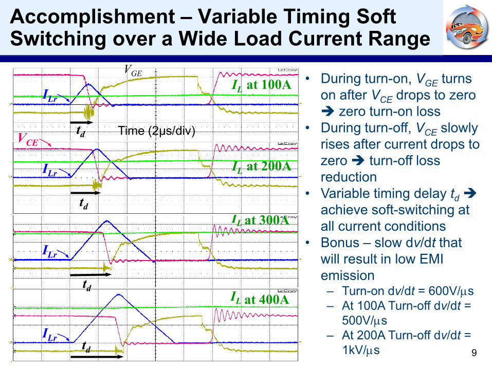
Accomplishment – Calorimeter Tested Efficiency Plots over a Long Period of Time
96.0%96.5%97.0%97.5%98.0%98.5%99.0%99.5%
100.0%
0 60 120 180 240 300 360Time (minutes)
Effic
ienc
y
96.0%96.5%97.0%97.5%98.0%98.5%99.0%99.5%
100.0%
0 60 120 180 240 300Time (minutes)
Effic
ienc
y
Motor speed: 2750 rpmMotor torque: 50 Nm
• Using integrated module with light-weight water manifold for the full-version soft-switching inverter.
• Calorimeter chamber inlet and outlet temperatures stabilized after 6-hour testing. Chamber temperature differential was 1.6 °C under 0.3 GPM flow rate.
• Efficiency exceeded 99% at full speed, 33% load torque condition.
(a) Test results at 12.5 kW
Motor speed: 2650 rpmMotor torque: 33 Nm
(b) Test results at 18 kW

16
Accomplishment – Soft Switched Inverter Efficiency Measurement using Calorimeter
Inverter Input (DC Link) Power Level
Inverter Heat Loss
Inverter Efficiency Dyno
SpeedTorque
17.5kW 192W 98.90% Azure AC552750rpm
50Nm
12.5kW 208W 98.30% Azure AC552650rpm
33Nm
27kW 311W 98.80% Azure AC901600rpm140Nm
-11.6kW (regen) 202W 98.30% Azure AC90-3800rpm
30Nm
GEN-1 SOFT SWITCHED INVERTER CALORIMETER TEST RESULTS
HARD SWITCHED INVERTER CALORIMETER TEST RESULTS
Inverter Input (DC Link) Power Level
Inverter Heat Loss
Inverter Efficiency Dyno
SpeedTorque
15.4kW 950W 93.80% Siemens1300rpm107Nm
19.7kW 709W 96.40% Siemens2400rpm
75Nm
23.7kW 626W 97.40% Siemens3400rpm
62Nm
-15.6kW (regen) 643W 96.00% Siemens-3000rpm
44Nm
17
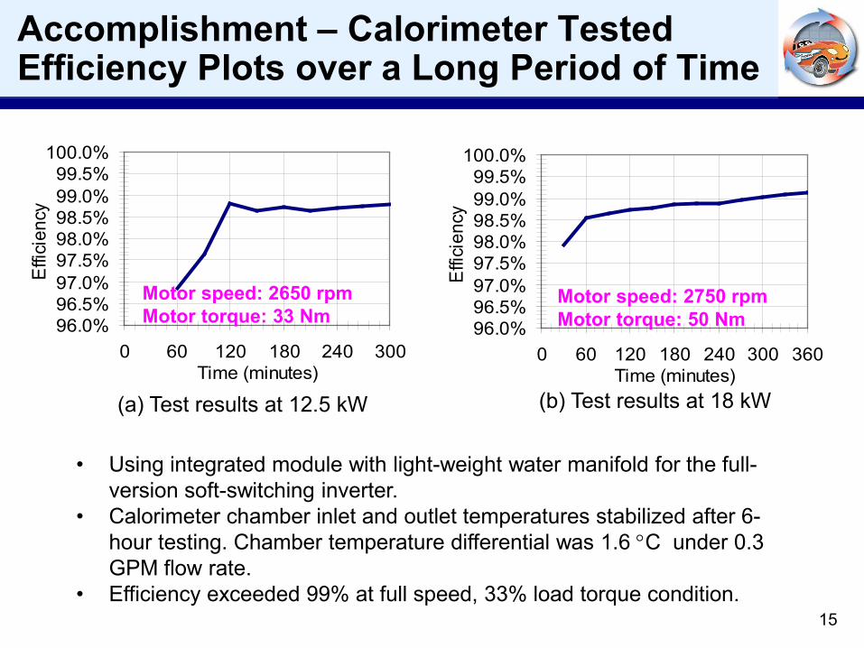
Accomplishment – Temperature Rise of Main Device Q1/M1 under Different Coolant Flow Rates
050
100150200250
0 20 40 60 80 100 120 140 160 180 200
0
5
10
15
20
0 20 40 60 80 100 120 140 160 180 200Current (A)
Pow
erlo
ss (W
)∆
T (º
C)
GPM = 0.2
GPM = 0.3
GPM = 0.8GPM = 1.0
GPM = 0.5
Worst case device temperature rise at 200-A continuous conducting condition is 4ºC With 1GPM flow rate 1.1psi pressure drop 20psi inlet pressure

18
Future Work
• Efficiency and EMI Testing with Gen-2 Soft-Switching Inverter
• Perform In-Vehicle Testing with Soft-Switching Inverter
• Complete More Efficient and Lower Cost Gen-3 Modules
• Manufacturability and Cost Analyses
Preparation for In-Vehicle Testing

19
Summary
• Variable timing control is successfully developed for high efficiency over a wide load range. The Gen-1 soft-switching inverter successfully demonstrates 99% efficiency, which was verified with calorimeter measurement.
• Worst-case junction temperature rise is less than 4ºC even with just 1-GPM coolant flow rate.
• Soft switching shows 10dB EMI reduction across entire frequency range and >20dB reduction between 3 and 6MHz
• Gen-2 soft-switching module can be cooled by either air or liquid. As compared to Gen-1 module, the Gen-2 soft-switching module demonstrates – Parasitic inductance reduction by 79% – Cost reduction by 84%